US6106213A - Automated door assembly for use in semiconductor wafer manufacturing - Google Patents
Automated door assembly for use in semiconductor wafer manufacturingDownload PDFInfo
- Publication number
- US6106213A US6106213AUS09/185,222US18522298AUS6106213AUS 6106213 AUS6106213 AUS 6106213AUS 18522298 AUS18522298 AUS 18522298AUS 6106213 AUS6106213 AUS 6106213A
- Authority
- US
- United States
- Prior art keywords
- pod
- opening
- platform
- closure plate
- door assembly
- Prior art date
- Legal status (The legal status is an assumption and is not a legal conclusion. Google has not performed a legal analysis and makes no representation as to the accuracy of the status listed.)
- Expired - Lifetime
Links
- 239000004065semiconductorSubstances0.000titleabstractdescription4
- 238000004519manufacturing processMethods0.000titledescription5
- 230000007246mechanismEffects0.000claimsabstractdescription42
- 230000033001locomotionEffects0.000claimsabstractdescription36
- 230000004888barrier functionEffects0.000claimsabstractdescription13
- 238000007789sealingMethods0.000claimsabstractdescription7
- 235000012431wafersNutrition0.000abstractdescription39
- 238000012545processingMethods0.000abstractdescription16
- 239000002245particleSubstances0.000abstractdescription5
- 238000004891communicationMethods0.000description5
- 238000013459approachMethods0.000description4
- 239000000356contaminantSubstances0.000description4
- 230000000694effectsEffects0.000description4
- 238000006073displacement reactionMethods0.000description3
- 230000003287optical effectEffects0.000description2
- 238000000926separation methodMethods0.000description2
- XUIMIQQOPSSXEZ-UHFFFAOYSA-NSiliconChemical compound[Si]XUIMIQQOPSSXEZ-UHFFFAOYSA-N0.000description1
- 238000005299abrasionMethods0.000description1
- 230000002411adverseEffects0.000description1
- 238000011109contaminationMethods0.000description1
- 238000011161developmentMethods0.000description1
- 239000000428dustSubstances0.000description1
- 238000013507mappingMethods0.000description1
- 238000012986modificationMethods0.000description1
- 230000004048modificationEffects0.000description1
- 238000003032molecular dockingMethods0.000description1
- 230000002028prematureEffects0.000description1
- 238000011160researchMethods0.000description1
- 230000000284resting effectEffects0.000description1
- 230000000717retained effectEffects0.000description1
- 229910052710siliconInorganic materials0.000description1
- 239000010703siliconSubstances0.000description1
- 230000001360synchronised effectEffects0.000description1
Images


Classifications
- H—ELECTRICITY
- H01—ELECTRIC ELEMENTS
- H01L—SEMICONDUCTOR DEVICES NOT COVERED BY CLASS H10
- H01L21/00—Processes or apparatus adapted for the manufacture or treatment of semiconductor or solid state devices or of parts thereof
- H01L21/67—Apparatus specially adapted for handling semiconductor or electric solid state devices during manufacture or treatment thereof; Apparatus specially adapted for handling wafers during manufacture or treatment of semiconductor or electric solid state devices or components ; Apparatus not specifically provided for elsewhere
- H01L21/677—Apparatus specially adapted for handling semiconductor or electric solid state devices during manufacture or treatment thereof; Apparatus specially adapted for handling wafers during manufacture or treatment of semiconductor or electric solid state devices or components ; Apparatus not specifically provided for elsewhere for conveying, e.g. between different workstations
- H01L21/67763—Apparatus specially adapted for handling semiconductor or electric solid state devices during manufacture or treatment thereof; Apparatus specially adapted for handling wafers during manufacture or treatment of semiconductor or electric solid state devices or components ; Apparatus not specifically provided for elsewhere for conveying, e.g. between different workstations the wafers being stored in a carrier, involving loading and unloading
- H01L21/67772—Apparatus specially adapted for handling semiconductor or electric solid state devices during manufacture or treatment thereof; Apparatus specially adapted for handling wafers during manufacture or treatment of semiconductor or electric solid state devices or components ; Apparatus not specifically provided for elsewhere for conveying, e.g. between different workstations the wafers being stored in a carrier, involving loading and unloading involving removal of lid, door, cover
- Y—GENERAL TAGGING OF NEW TECHNOLOGICAL DEVELOPMENTS; GENERAL TAGGING OF CROSS-SECTIONAL TECHNOLOGIES SPANNING OVER SEVERAL SECTIONS OF THE IPC; TECHNICAL SUBJECTS COVERED BY FORMER USPC CROSS-REFERENCE ART COLLECTIONS [XRACs] AND DIGESTS
- Y10—TECHNICAL SUBJECTS COVERED BY FORMER USPC
- Y10S—TECHNICAL SUBJECTS COVERED BY FORMER USPC CROSS-REFERENCE ART COLLECTIONS [XRACs] AND DIGESTS
- Y10S414/00—Material or article handling
- Y10S414/135—Associated with semiconductor wafer handling
- Y10S414/139—Associated with semiconductor wafer handling including wafer charging or discharging means for vacuum chamber
- Y—GENERAL TAGGING OF NEW TECHNOLOGICAL DEVELOPMENTS; GENERAL TAGGING OF CROSS-SECTIONAL TECHNOLOGIES SPANNING OVER SEVERAL SECTIONS OF THE IPC; TECHNICAL SUBJECTS COVERED BY FORMER USPC CROSS-REFERENCE ART COLLECTIONS [XRACs] AND DIGESTS
- Y10—TECHNICAL SUBJECTS COVERED BY FORMER USPC
- Y10S—TECHNICAL SUBJECTS COVERED BY FORMER USPC CROSS-REFERENCE ART COLLECTIONS [XRACs] AND DIGESTS
- Y10S414/00—Material or article handling
- Y10S414/135—Associated with semiconductor wafer handling
- Y10S414/14—Wafer cassette transporting
Definitions
- This inventionrelates to semiconductor fabrication wafer handling apparatus, and specifically to an automated door assembly to provide controlled access to a substantially contaminant free treatment environment for wafers disposed therein.
- Wafer fabrication operations for producing silicon wafers suitable for use with microprocessors, computer memory, and other microcircuitsmust be carried out in a substantially contaminant-free environment. Airborne particles such as dust and dirt can compromise the quality of the resulting wafer. Excessive foreign matter results in a lower yield of usable wafers from a particular batch. Increasingly dense arrangement of circuit elements on a wafer, or chip, further heightens the quality required to produce a usable wafer. Accordingly, such fabrication operations are often performed in a sealed, substantially contaminant-free processing environment.
- This processing Express Mail Number environmentreferred to as the tool side of the wall, contains tools and apparatus for effecting such processing.
- the operator side of the walltransport of the wafers between processing stations occurs by human or robotic operators.
- the opening in the wallmust be capable of being sealed sufficiently by a door assembly to maintain the contaminant-free state on the tool side, but also be readily unsealed to provide expedient and unobstructed access between the operator and tool sides when needed.
- Such a seal between the door assembly and the openingoften involves close tolerances between moving parts, which raises issues of friction and inaccurate sealing, as wear-and-tear affects the seal mechanism.
- the wafersare often stored in a sealed cassette called a pod when they are not in the processing environment on the tool side.
- Such podsare designed to engage and seal against the opening in the wall from the operator side to allow the wafers to be accessed by a mechanism from the tool side while maintaining the separation between the processing environment and the operator side environment. This separation is achieved by abutting the pod in sealing engagement with the operator side of the wall adjacent the opening therein. Then, the pod door is engaged by the door assembly, unlocked from the pod, and drawn by the door assembly into the tool side. In this manner, the outer perimeter of the pod opening remains sealably engaged with the outer perimeter of the opening in the wall.
- the wafers inside the podare accessible for processing by apparatus on the tool side.
- the wafersare returned to the pod and the door assembly is moved to reengage the pod door with the pod, thereby also closing the opening in the wall with the door assembly.
- the podmust remain undisturbed when the pod door is open to the processing environment, as manipulation of the pod, such as accidental removal, could disturb the seal and cause physical damage to the wafers.
- Automation of such a wafer handling and treatment operationis therefore burdened by the need to manipulate the door assembly and pod door within these close tolerances, the need to accurately reengage with and reseal the pod door and wall opening following wafer treatment, and the need to secure the pod during treatment to avoid accidental removal.
- Movement of a door assembly concealing such an openingis typically along two orthogonal axes.
- a pivoting mechanismis used to effect movement along a single arcuate path.
- the present applicationrelates to an automated door assembly and pod latching apparatus for selectively engaging and sealing an opening in a wall which provides access to a substantially contaminant-free environment for wafer processing.
- the automated door assemblycomprises a base pivotably mounted to a fixed support surface in the sealed environment, and a closure plate linearly movably coupled to the base.
- the closure plateis configured to seal the opening in the barrier.
- a closure mechanismis provided comprising a pivoting drive assembly coupled to the base and operable to pivot the base toward and away from the opening along an arcuate path.
- the closure mechanismalso comprises a linear horizontal drive assembly coupled to the closure plate and operable in synchronization with the pivoting drive assembly to force the closure plate to follow a horizontal linear path along an upper portion of the arcuate path of the base adjacent and into contact with the barrier to close the opening.
- the door assemblyalso comprises an extendable and retractable arm coupled to the base.
- the closure plateis disposed on an upper end of the extendable and retractable arm.
- the armWhen the door assembly is in a fully open position and is not sealed against the opening, the arm is in a retracted position pivoted slightly away from the barrier. As the arm is extended, the closure plate approaches the opening until it reaches a point substantially in front of and obscuring the opening. At this point, the base then pivots inward so that the closure plate approaches the opening on an arcuate path. As the closure plate approaches a position closer to the opening, the linear horizontal drive assembly linearizes the movement of the closure plate. In this manner, the closure plate is directly aligned on a linear path perpendicular to the opening rather than oriented on an arcuate docking path. This engagement provides accurate, effective sealing of the portal door with little force required to overcome friction between the closure plate and the edge of the opening which would otherwise be encountered when moving the closure plate on an arcuate path within close tolerances.
- a container latching apparatusfor latching a container such as a wafer pod or cassette in sealing engagement with the opening on the operator side of the barrier.
- the container latching apparatuscomprises a container or pod support disposed proximate to the opening in the barrier.
- a platformis linearly movably coupled to the container support.
- a drive mechanismis coupled to the container support and the platform and is operative to linearly drive the platform with respect to the container support toward and away from the opening in the barrier.
- a locking mechanismconfigured to mate with a corresponding mechanism on the container or pod, is rotatably mounted to the container or pod support and coupled to the platform for linear motion therewith.
- the platformhas mounting pins having beveled upper edges or V-shaped tops for engaging with beveled slots or openings on the underside of the pod to restrict lateral movement of the pod.
- the platformAfter the pod is placed on the platform, the platform is disposed towards the opening and the locking mechanism is rotationally engaged with the corresponding pod locking mechanism to lock the pod.
- the closure plate of the door assemblylatches onto the pod door, in a manner known in the art, and both are opened enabling the wafers to be processed by various apparatus within the processing environment or tool side.
- the podis secured to the platform by the container latching apparatus, thereby preventing premature removal of the pod, which could lead to wafer damage or contamination of the contaminant-free environment.
- vertical movement of the closure plateis effected independent of the pivoting movement through the use of a high-resolution servo motor combined with a high-ratio gearbox to drive the extendable portion of the arm via a drive belt.
- the high-resolution motorworks in conjunction with a sensor, such as a optical scanner, provided on the closure plate to sense misplacement of wafers or missing wafers by mapping their location based on motor displacement.
- a closure platewhich is readily detachable from the arm, and further, a bezel insert containing the opening to allow the apparatus to accommodate different sized pods by replacing the closure plate and opening bezel insert to correspond to different size pods.
- the basecomprises a closed container having an opening therein.
- the closure plateis attached to at least one riser extending through the opening.
- a vacuum assemblyis disposed adjacent to the opening and coupled to an ambient environment, such as the operator side or outside, and operable to provide a vacuum around the opening, whereby particles within the closed container are extractable to the ambient environment.
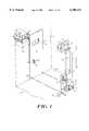
- FIG. 1is an isometric exploded view of the automated door assembly and pod latching apparatus from the tool side;
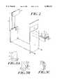
- FIG. 2is an isometric exploded view of the automated door opener and pod retraction apparatus from the operator side;
- FIG. 3ais a right side view of a door closure cam of the present invention.
- FIG. 3bis a left side view of the door closure cam of FIG. 3a;
- FIG. 3cis an isometric view of the door closure cam of FIG. 3a;
- FIG. 4is an exploded isometric view of a portion of the containment wall between the tool side and the operator side, as seen from the operator side.
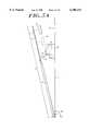
- FIG. 5ais a schematic illustration of the automated door assembly in an extended position.
- FIG. 5bis a schematic illustration of the automated door assembly in a further extended position
- FIG. 5cis a schematic illustration of the automated door assembly in a closed position
- FIG. 6ais a schematic illustration of the automated door assembly in an extended position.
- FIG. 6bis a schematic illustration of the automated door assembly in a further extended position
- FIG. 6cis a schematic illustration of the automated door assembly in a closed position
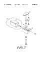
- FIG. 7is an exploded isometric view of a portion of the latch mechanism of the present invention.
- FIG. 8ais a schematic, partially cut-away plan view of the pod support retracted away from the door assembly
- FIG. 8bis a schematic, partially cut-away plan view of the pod support in an intermediate position
- FIG. 8cis a schematic, partially cut-away plan view of the pod platform at the engaged position locking the pod in place;
- FIG. 9is a schematic side view of a further embodiment of the present invention illustrating a high-resolution drive mechanism and wafer sensor mechanism
- FIG. 10is a schematic isometric view of a further embodiment illustrating vacuum tubes around the door support tubes
- FIGS. 11a & bare schematic views of a further embodiment illustrating interchangeable closure plates
- FIGS. 12a & bare schematic views of the interchangeable door bezels for accommodating different closure plates of FIGS. 11a & b.
- an automated door assembly 18 and pod latching apparatus 19are disclosed.
- the door assemblyis located on the tool side of a wall 17 separating the tool side from the operator side, and is operable to seal an opening 12 in the wall through which wafers may pass.
- the wall 17 or a portion thereofmay be at an angle of less than 900 with respect to the floor 65, for reasons discussed further below.
- a pod support 50 of the pod latching apparatus 19is located on the operator side of the wall 17 for supporting a pod 38. The pod support is operable to position the pod in locking engagement with the opening 12 such that the door assembly 18 is operable to latch onto the pod door, in a known manner, and retract it into the tool side while the opening remains sealed from the operator side by the pod, as described further below.
- the door assembly 18is adapted to be received by the opening 12. Opening 12 is sealed by closure plate 10 when the arm 14 of door assembly 18 is extended and pivoted about axis 8.
- the door assembly 18approaches the opening 12 first by extending a closure plate 10 upward toward the opening, then by pivoting the door assembly 18 towards the opening 12 about pivot points 20. Then, as it nears the opening, the closure plate 10 traverses a linear, rather than an arcuate, path until it engages the opening 12 by a mechanism 30 described further below.
- rotatable T-shaped latch 44rotates within oval-shaped pod locking receptacle, securing pod 38 to pod platform 36.
- Door 10then engages latch 40 with pod door 42 such that door 10 and pod door 42 can be removed as one unit by closure arm door assembly 18.
- the door assembly 18includes a base 16 and an arm 14 mounted to the base 16 for extension and retraction.
- the base 16is mounted for pivoting about a horizontal axis 8 through pivot points 20 at the lower end of the base 16.
- the closure plate 10is mounted at an end of the arm 14 opposite the base 16. When the arm 14 is in an extended position, the closure plate 10 is sealable against the opening in the wall 12 to maintain the contaminant free environment on the tool side 13.
- the closure plate 10includes a pod door engagement mechanism 11 which is operable to engage the pod door 42.
- the armis shown having two tubular risers 90 & 92, although any suitable configuration, such 5 as a single riser or three or more tubular risers, could be provided.
- the armcould be other than tubular, if desired.
- the armmay be extended and retracted by any suitable mechanism, such as the drive belt 23, linear rail 27, rise drive block 29 and servo motor mechanism 22 as shown in FIGS. 1 & 9.
- a controlleris provided in communication with the motor mechanism to control operation thereof.
- the tubular risers 90, 92are inserted into the riser drive block 29.
- the door assembly 18With the pod door 42 engaged on the closure plate 10, the door assembly 18 is operable to retract the closure plate 10 along a horizontal linear path 15 away from the opening 12. When the closure plate 10 and pod door 42 have sufficiently cleared the opening 12, the door assembly 18 is operable to retract the arm 14, thereby lowering the closure plate 10 and pod door 42 away from the opening and allowing access to the wafers in a pod 38 by the tools on the tool side 13. After processing, the wafers are returned to the pod 38 and the door assembly 18 motions are reversed to close the opening with the closure plate 10 and return the pod door 42 to the pod 38.
- the arm 14is extended linearly to move the closure plate 10 upwardly from the base 16.
- the baseis pivoted about the horizontal axis 8 to move the closure plate 10 toward the opening 12.
- the arm 14 and closure plate 10are retracted linearly downward in synchronization with the pivoting motion of the base to effect a substantially horizontal linear motion 15 of the closure plate 10 perpendicular to the wall 17 and the opening therein 12.
- the closure plateseals the opening cleanly without adverse consequences of a vertical component of motion on the perimeter of the opening, thereby minimizing wear on the opening and the closure plate and extending their useful life.
- the horizontal linear motion of the closure plate 10is achieved by a closure cam mechanism 30.
- the closure cam mechanism 30is mounted to or fixed with respect to the wall 17 and extends through a slot 31 or other suitable aperture in the base 16.
- On one side of the cam mechanism 30is provided an S-shaped cam surface 28.
- a horizontal upper cam surface 34is provided, on the other side of the cam mechanism 30, below the S-shaped cam surface 28.
- a horizontal cam roller 32 engageable with the horizontal cam surface 34is mounted to the arm 14. As the arm is extended upwardly, the horizontal cam roller 32 abuts the horizontal cam surface 34 and prevents a further upward component of motion of the arm 14 and closure plate 10.
- a pivot cam roller 24 engaged within the S-shaped cam surface 28is mounted on the base 16 and in communication with a drive mechanism 25, such as a piston and cylinder operable under the control of the controller 84, which provides upward and downward motion.
- a drive mechanism 25such as a piston and cylinder operable under the control of the controller 84, which provides upward and downward motion.
- the S-shaped cam surfacecauses the pivot cam roller 24 to move toward the wall 17, thereby driving the door assembly 18 toward the wall by pivoting of the base 16 about its pivot axis 8.
- the arm 14is driven upward.
- the S-cam drive mechanism 25is actuated to drive the S-cam roller 24 upward to effect pivoting motion of the door assembly 18.
- the horizontal cam roller 32slidably engages the horizontal cam surface 34, thereby preventing any further vertical component of motion of the closure plate 10 and arm 14.
- the closure platefollows a horizontal linear path 15 perpendicular to the wall 17 into engagement with the opening 12 in the wall 17.
- the closure platein effect moves linearly downward with respect to the base a distance sufficient, when synchronized with the arcuate motion of the base, to achieve substantially horizontal linear motion perpendicular to the wall 17.
- the closure platecan be moved linearly downwardly with respect to the base against the operation of the motor 22, or alternatively the motor 22 can be operated to drive the closure plate downwardly.
- the cam mechanism 30also includes a lower horizontal surface 33 opposite the upper horizontal surface 34, as shown in FIGS. 3, 4 and 5a-c.
- the horizontal cam roller 32is engageable with the lower surface 33 when the closure plate 10 is sealed against the opening 12, thereby preventing any vertically downward motion of the closure plate 10.
- This surface 33is particularly useful in the event of a power failure to ensure that the closure plate 10 remains sealed against the opening 12 and does not drop away therefrom, potentially damaging the perimeter of the opening and allowing contaminants to enter into the tool side 13.
- a pod locking mechanismis provided.
- the pod locking mechanismincludes a pod platform 36 on the pod support 50 which is drivable linearly toward and away from the opening 12 in the wall 17.
- a plurality of upstanding pins 52are provided which mate with a corresponding plurality of apertures 54 in a bottom surface of the pod.
- Preferably three pins and aperturesare provided since three points are sufficient to locate the pod 38 with respect to the platform 36 without introducing any gap between the pod 38 and the pod platform 36.
- tops of the pins 52are beveled, or V-shaped, as are the sides of the apertures to allow the pod to settle on the pins in an appropriate position, thereby allowing for slight variations in the openings 54 and to facilitate placement of the pods on the platform.
- the pod 38also has an oval aperture 46 or slot in the bottom surface.
- the pod platform 36includes a T-shaped latch 44 which is rotationally mounted to the underside of the platform.
- a pivoting link 56is attached to the latch 44 at one end.
- An opposite end of the linkis retained in pivoting and slidable communication with a linear slot 58 in the pod support 50 disposed orthogonally to the direction of liner motion of the platform 36.
- the upper portion of the T-shaped latch 44extends through the slot in the pod 46 such that, as the latch is rotated, the outer ends of the upper portion rotate out of alignment with the slot 46 to secure the pod 38 to the pod platform 36.
- simple linear movement of the pod platformis used to additionally provide the latching of the pod to the pod platform.
- the platformis driven away from the opening 12 in the wall, thereby reversing movement of the T-shaped latch 44 until it aligns with the slot 46 in the pod. At this point, the pod 38 can be freely lifted off the platform 36.
- sensor 60in communication with the controller 84 is shown attached to the closure plate 10.
- sensor 60is an optical device for detecting wafers positioned in the pod on opposing, coplanar ridges 62 mounted on the interior side of the pod 38.
- Sensor positioncan then be accurately determined by the controller by belt displacement 16 derived from the number of rotations of the motor 22.
- Sensor 60detects the position of wafers 64 resting on ridges 62.
- the retracted position of the arm 14is vertical and perpendicular to the floor 65, while the wall 17 is slightly angled outward from the upper end of the arm 14 as indicated by angle E, and in the preferred embodiment is approximately 87°, although the exact angle is not critical.
- Ridges 62 and therefore, wafers 64are likewise perpendicular to the retracted position of the arm 14. This perpendicular orientation of the retracted arm insures that wafers 64 are a uniform distance from sensor 60 throughout the travel path across the open pod 38. Therefore, the topmost wafer in the pod 38 is the same distance from sensor 60 as the bottom wafer. Missing and uneven (mounted on non-coplanar ridges) wafers can therefore be detected by comparison of belt displacement to predetermined ridge heights within the pod 38.
- Arm 14is comprised of two hollow riser tubes 90, 92 which are extended from the base 16 through apertures 76 in the top side of the base 16. Due to low pressure in the closure assembly 18 which occurs as the arm risers 90, 92 are driven upwards, particles will tend to be drawn into the base 16. Thus, a narrow tolerance is maintained between apertures 76 and arm riser tubes 90 and 92.
- a vacuum ring tube 70 powered by external vacuum source 74 through vacuum tube 72is located surrounding each aperture 76. These vacuum rings serve to extract particles which occur as a result of abrasion around the narrow tolerance between the apertures 76 and the arm risers 90, 92 to an ambient environment, such as the operator side or outside.
- an interchangeable closure plate 10 and opening 12are disclosed. As the size of the opening 12 must be matched to the pod 38 to be processed, alternate sized pods could not be addressed by a single door assembly. Opening 12 is mounted in wall 17 through a bezel plate 80. A plurality of bezel plates 80 having consistent outer dimensions but varying openings 12 can be interchanged among their mounting in respective walls 17. Further, a plurality of closure plates 10 have a mounting bracket 82 which attaches to closure arms 14 consistently but having varying outer dimensions to match a corresponding opening 12 in a particular bezel plate 80. Therefore, a particular door closure mechanism 18 could be adapted to address varying sized pods 38 by merely exchanging bezel plate 80 and closure plate 10 with a pair corresponding to the pod size to be serviced.
- the horizontal motion of the closure platecan be decoupled from the pivoting motion of the base, such as by driving the closure plate downwardly with the motor 22 under control of the controller 84.
- a drive mechanism which provides rotary motion of the base about the axis 8can be used, rather than a mechanism which uses linear motion and suitably configured cam surfaces to achieve the pivoting motion.
Landscapes
- Engineering & Computer Science (AREA)
- Physics & Mathematics (AREA)
- Condensed Matter Physics & Semiconductors (AREA)
- General Physics & Mathematics (AREA)
- Manufacturing & Machinery (AREA)
- Computer Hardware Design (AREA)
- Microelectronics & Electronic Packaging (AREA)
- Power Engineering (AREA)
- Container, Conveyance, Adherence, Positioning, Of Wafer (AREA)
Abstract
Description
Claims (3)
Priority Applications (4)
| Application Number | Priority Date | Filing Date | Title |
|---|---|---|---|
| US09/185,222US6106213A (en) | 1998-02-27 | 1998-11-03 | Automated door assembly for use in semiconductor wafer manufacturing |
| EP99909655AEP1165412A4 (en) | 1998-02-27 | 1999-02-26 | Door assembly for semiconductor wafer manufacturing |
| PCT/US1999/004307WO1999043582A1 (en) | 1998-02-27 | 1999-02-26 | Door assembly for semiconductor wafer manufacturing |
| US09/641,996US6447233B1 (en) | 1998-02-27 | 2000-08-18 | Automated door assembly for use in semiconductor wafer manufacturing |
Applications Claiming Priority (2)
| Application Number | Priority Date | Filing Date | Title |
|---|---|---|---|
| US7622398P | 1998-02-27 | 1998-02-27 | |
| US09/185,222US6106213A (en) | 1998-02-27 | 1998-11-03 | Automated door assembly for use in semiconductor wafer manufacturing |
Related Child Applications (1)
| Application Number | Title | Priority Date | Filing Date |
|---|---|---|---|
| US09/641,996ContinuationUS6447233B1 (en) | 1998-02-27 | 2000-08-18 | Automated door assembly for use in semiconductor wafer manufacturing |
Publications (1)
| Publication Number | Publication Date |
|---|---|
| US6106213Atrue US6106213A (en) | 2000-08-22 |
Family
ID=26757820
Family Applications (2)
| Application Number | Title | Priority Date | Filing Date |
|---|---|---|---|
| US09/185,222Expired - LifetimeUS6106213A (en) | 1998-02-27 | 1998-11-03 | Automated door assembly for use in semiconductor wafer manufacturing |
| US09/641,996Expired - LifetimeUS6447233B1 (en) | 1998-02-27 | 2000-08-18 | Automated door assembly for use in semiconductor wafer manufacturing |
Family Applications After (1)
| Application Number | Title | Priority Date | Filing Date |
|---|---|---|---|
| US09/641,996Expired - LifetimeUS6447233B1 (en) | 1998-02-27 | 2000-08-18 | Automated door assembly for use in semiconductor wafer manufacturing |
Country Status (3)
| Country | Link |
|---|---|
| US (2) | US6106213A (en) |
| EP (1) | EP1165412A4 (en) |
| WO (1) | WO1999043582A1 (en) |
Cited By (16)
| Publication number | Priority date | Publication date | Assignee | Title |
|---|---|---|---|---|
| US6375403B1 (en)* | 1995-03-28 | 2002-04-23 | Brooks Automation, Gmbh | Loading and unloading station for semiconductor processing installations |
| WO2002004322A3 (en)* | 2000-07-10 | 2002-04-25 | Asyst Technologies | SMIF container latch mechanism |
| US6517304B1 (en)* | 1999-03-31 | 2003-02-11 | Canon Kabushiki Kaisha | Method for transporting substrates and a semiconductor manufacturing apparatus using the method |
| US20030090284A1 (en)* | 2001-11-09 | 2003-05-15 | Webb Fred C. | Device and method for opening a door |
| US6585828B1 (en)* | 2000-09-26 | 2003-07-01 | Applied Materials, Inc. | Process chamber lid service system |
| US20040213648A1 (en)* | 2003-04-14 | 2004-10-28 | Hofmeister Christopher A | Substrate cassette mapper |
| US20050265812A1 (en)* | 2004-05-28 | 2005-12-01 | Tdk Corporation | Load port for clean system |
| US20060263178A1 (en)* | 2000-07-07 | 2006-11-23 | Applied Materials, Inc. | Automatic door opener |
| US20080031709A1 (en)* | 2006-07-10 | 2008-02-07 | Bonora Anthony C | Variable lot size load port |
| US20100133270A1 (en)* | 2008-11-28 | 2010-06-03 | Tdk Corporation | Lid opening/closing system for closed container |
| WO2012003240A3 (en)* | 2010-06-30 | 2012-04-12 | Crossing Automation, Inc. | Port door positioning apparatus and associated methods |
| US20120315114A1 (en)* | 2011-06-07 | 2012-12-13 | Tokyo Electron Limited | Substrate conveying container opening/closing device, lid opening/closing device and semiconductor manufacturing apparatus |
| JP2014112631A (en)* | 2012-10-31 | 2014-06-19 | Tdk Corp | Load port unit and EFEM system |
| JPWO2013005363A1 (en)* | 2011-07-06 | 2015-02-23 | 平田機工株式会社 | Container opening and closing device |
| US20150364346A1 (en)* | 2013-01-14 | 2015-12-17 | Pico&Tera Co., Ltd. | Exhaust system of wafer treatment device |
| US11348818B2 (en)* | 2020-10-14 | 2022-05-31 | Taiwan Semiconductor Manufacturing Company Ltd. | Slit door assembly and method of operating the same |
Families Citing this family (4)
| Publication number | Priority date | Publication date | Assignee | Title |
|---|---|---|---|---|
| US5186594A (en)* | 1990-04-19 | 1993-02-16 | Applied Materials, Inc. | Dual cassette load lock |
| US6827546B2 (en)* | 2002-08-19 | 2004-12-07 | Brooks-Pri Automation, Inc. | Modular frame for a wafer fabrication system |
| US7770330B2 (en)* | 2007-12-19 | 2010-08-10 | General Electric Company | Method of opening an appliance door |
| JP5736686B2 (en) | 2010-08-07 | 2015-06-17 | シンフォニアテクノロジー株式会社 | Load port |
Citations (16)
| Publication number | Priority date | Publication date | Assignee | Title |
|---|---|---|---|---|
| US4739882A (en)* | 1986-02-13 | 1988-04-26 | Asyst Technologies | Container having disposable liners |
| US4776744A (en)* | 1985-09-09 | 1988-10-11 | Applied Materials, Inc. | Systems and methods for wafer handling in semiconductor process equipment |
| US5246218A (en)* | 1992-09-25 | 1993-09-21 | Intel Corporation | Apparatus for securing an automatically loaded wafer cassette on a wafer processing equipment |
| US5586585A (en)* | 1995-02-27 | 1996-12-24 | Asyst Technologies, Inc. | Direct loadlock interface |
| US5607276A (en)* | 1995-07-06 | 1997-03-04 | Brooks Automation, Inc. | Batchloader for substrate carrier on load lock |
| US5615988A (en)* | 1995-07-07 | 1997-04-01 | Pri Automation, Inc. | Wafer transfer system having rotational capability |
| US5628683A (en)* | 1992-03-09 | 1997-05-13 | Josef Gentischer | System for transferring substrates into clean rooms |
| US5647718A (en)* | 1995-07-07 | 1997-07-15 | Pri Automation, Inc. | Straight line wafer transfer system |
| US5653565A (en)* | 1995-07-05 | 1997-08-05 | Asyst Technologies, Inc. | SMIF port interface adaptor |
| US5673804A (en)* | 1996-12-20 | 1997-10-07 | Pri Automation, Inc. | Hoist system having triangular tension members |
| US5683124A (en)* | 1995-04-03 | 1997-11-04 | Karpisek; Ladislav Stephan | Latching device for a hinged panel |
| US5741109A (en)* | 1995-07-07 | 1998-04-21 | Pri Automation, Inc. | Wafer transfer system having vertical lifting capability |
| US5772386A (en)* | 1995-03-28 | 1998-06-30 | Jenoptik Ag | Loading and unloading station for semiconductor processing installations |
| US5810537A (en)* | 1995-10-18 | 1998-09-22 | Bye/Oasis Engineering Inc. | Isolation chamber transfer apparatus |
| US5829939A (en)* | 1993-04-13 | 1998-11-03 | Tokyo Electron Kabushiki Kaisha | Treatment apparatus |
| US5848933A (en)* | 1995-07-18 | 1998-12-15 | Semifab, Incorporated | Docking and environmental purging system for integrated circuit wafer transport assemblies |
Family Cites Families (4)
| Publication number | Priority date | Publication date | Assignee | Title |
|---|---|---|---|---|
| US5186594A (en)* | 1990-04-19 | 1993-02-16 | Applied Materials, Inc. | Dual cassette load lock |
| DE19542646C2 (en)* | 1995-03-28 | 2003-04-30 | Brooks Automation Gmbh | Loading and unloading station for semiconductor processing systems |
| US5837059A (en)* | 1997-07-11 | 1998-11-17 | Brooks Automation, Inc. | Automatic positive pressure seal access door |
| US6082951A (en)* | 1998-01-23 | 2000-07-04 | Applied Materials, Inc. | Wafer cassette load station |
- 1998
- 1998-11-03USUS09/185,222patent/US6106213A/ennot_activeExpired - Lifetime
- 1999
- 1999-02-26EPEP99909655Apatent/EP1165412A4/ennot_activeWithdrawn
- 1999-02-26WOPCT/US1999/004307patent/WO1999043582A1/ennot_activeApplication Discontinuation
- 2000
- 2000-08-18USUS09/641,996patent/US6447233B1/ennot_activeExpired - Lifetime
Patent Citations (16)
| Publication number | Priority date | Publication date | Assignee | Title |
|---|---|---|---|---|
| US4776744A (en)* | 1985-09-09 | 1988-10-11 | Applied Materials, Inc. | Systems and methods for wafer handling in semiconductor process equipment |
| US4739882A (en)* | 1986-02-13 | 1988-04-26 | Asyst Technologies | Container having disposable liners |
| US5628683A (en)* | 1992-03-09 | 1997-05-13 | Josef Gentischer | System for transferring substrates into clean rooms |
| US5246218A (en)* | 1992-09-25 | 1993-09-21 | Intel Corporation | Apparatus for securing an automatically loaded wafer cassette on a wafer processing equipment |
| US5829939A (en)* | 1993-04-13 | 1998-11-03 | Tokyo Electron Kabushiki Kaisha | Treatment apparatus |
| US5586585A (en)* | 1995-02-27 | 1996-12-24 | Asyst Technologies, Inc. | Direct loadlock interface |
| US5772386A (en)* | 1995-03-28 | 1998-06-30 | Jenoptik Ag | Loading and unloading station for semiconductor processing installations |
| US5683124A (en)* | 1995-04-03 | 1997-11-04 | Karpisek; Ladislav Stephan | Latching device for a hinged panel |
| US5653565A (en)* | 1995-07-05 | 1997-08-05 | Asyst Technologies, Inc. | SMIF port interface adaptor |
| US5607276A (en)* | 1995-07-06 | 1997-03-04 | Brooks Automation, Inc. | Batchloader for substrate carrier on load lock |
| US5647718A (en)* | 1995-07-07 | 1997-07-15 | Pri Automation, Inc. | Straight line wafer transfer system |
| US5741109A (en)* | 1995-07-07 | 1998-04-21 | Pri Automation, Inc. | Wafer transfer system having vertical lifting capability |
| US5615988A (en)* | 1995-07-07 | 1997-04-01 | Pri Automation, Inc. | Wafer transfer system having rotational capability |
| US5848933A (en)* | 1995-07-18 | 1998-12-15 | Semifab, Incorporated | Docking and environmental purging system for integrated circuit wafer transport assemblies |
| US5810537A (en)* | 1995-10-18 | 1998-09-22 | Bye/Oasis Engineering Inc. | Isolation chamber transfer apparatus |
| US5673804A (en)* | 1996-12-20 | 1997-10-07 | Pri Automation, Inc. | Hoist system having triangular tension members |
Cited By (38)
| Publication number | Priority date | Publication date | Assignee | Title |
|---|---|---|---|---|
| US6837663B2 (en) | 1995-03-28 | 2005-01-04 | Brooks Automation, Inc. | Loading and unloading station for semiconductor processing installations |
| US6461094B1 (en) | 1995-03-28 | 2002-10-08 | Jenoptik Ag | Loading and unloading station for semiconductor processing installations |
| US6375403B1 (en)* | 1995-03-28 | 2002-04-23 | Brooks Automation, Gmbh | Loading and unloading station for semiconductor processing installations |
| US6609876B2 (en) | 1995-03-28 | 2003-08-26 | Brooks Automation, Inc. | Loading and unloading station for semiconductor processing installations |
| US6517304B1 (en)* | 1999-03-31 | 2003-02-11 | Canon Kabushiki Kaisha | Method for transporting substrates and a semiconductor manufacturing apparatus using the method |
| US7467919B2 (en)* | 2000-07-07 | 2008-12-23 | Applied Materials, Inc. | Automatic door opener |
| US20060263178A1 (en)* | 2000-07-07 | 2006-11-23 | Applied Materials, Inc. | Automatic door opener |
| WO2002004322A3 (en)* | 2000-07-10 | 2002-04-25 | Asyst Technologies | SMIF container latch mechanism |
| US6536813B2 (en) | 2000-07-10 | 2003-03-25 | Asyst Technologies, Inc. | SMIF container latch mechanism |
| US6585828B1 (en)* | 2000-09-26 | 2003-07-01 | Applied Materials, Inc. | Process chamber lid service system |
| WO2003040499A3 (en)* | 2001-11-09 | 2004-03-04 | Knaack Mfg | Device and method for opening a door |
| US6883274B2 (en)* | 2001-11-09 | 2005-04-26 | Knaack Manufacturing Company | Device and method for opening a door |
| US20030090284A1 (en)* | 2001-11-09 | 2003-05-15 | Webb Fred C. | Device and method for opening a door |
| US20040213648A1 (en)* | 2003-04-14 | 2004-10-28 | Hofmeister Christopher A | Substrate cassette mapper |
| US7255524B2 (en)* | 2003-04-14 | 2007-08-14 | Brooks Automation, Inc. | Substrate cassette mapper |
| US20050265812A1 (en)* | 2004-05-28 | 2005-12-01 | Tdk Corporation | Load port for clean system |
| US20080031709A1 (en)* | 2006-07-10 | 2008-02-07 | Bonora Anthony C | Variable lot size load port |
| US8657346B2 (en)* | 2008-11-28 | 2014-02-25 | Tdk Corporation | Lid opening/closing system for closed container |
| US20100133270A1 (en)* | 2008-11-28 | 2010-06-03 | Tdk Corporation | Lid opening/closing system for closed container |
| WO2012003240A3 (en)* | 2010-06-30 | 2012-04-12 | Crossing Automation, Inc. | Port door positioning apparatus and associated methods |
| JP2015128197A (en)* | 2010-06-30 | 2015-07-09 | ブルックス オートメーション インコーポレイテッド | Port door positioning apparatus and related method |
| JP2013539203A (en)* | 2010-06-30 | 2013-10-17 | ブルックス オートメーション インコーポレイテッド | Port door positioning apparatus and related method |
| CN106024680B (en)* | 2010-06-30 | 2019-02-19 | 布鲁克斯自动化公司 | Port door positioning device and related methods |
| CN106024680A (en)* | 2010-06-30 | 2016-10-12 | 布鲁克斯自动化公司 | Port door positioning apparatus and associated methods |
| US8870516B2 (en) | 2010-06-30 | 2014-10-28 | Brooks Automation, Inc. | Port door positioning apparatus and associated methods |
| US20150021230A1 (en)* | 2010-06-30 | 2015-01-22 | Brooks Automation, Inc. | Port Door Positioning Apparatus and Associated Methods |
| CN103155132B (en)* | 2010-06-30 | 2016-08-03 | 布鲁克斯自动化公司 | Port door positioning device and related method |
| US9378995B2 (en)* | 2010-06-30 | 2016-06-28 | Brooks Automation, Inc. | Port door positioning apparatus and associated methods |
| CN103155132A (en)* | 2010-06-30 | 2013-06-12 | 布鲁克斯自动化公司 | Port door positioning device and related method |
| US9048273B2 (en)* | 2011-06-07 | 2015-06-02 | Tokyo Electron Limited | Substrate conveying container opening/closing device, lid opening/closing device and semiconductor manufacturing apparatus |
| US20120315114A1 (en)* | 2011-06-07 | 2012-12-13 | Tokyo Electron Limited | Substrate conveying container opening/closing device, lid opening/closing device and semiconductor manufacturing apparatus |
| US9324599B2 (en) | 2011-07-06 | 2016-04-26 | Hirata Corporation | Container opening/closing device |
| JPWO2013005363A1 (en)* | 2011-07-06 | 2015-02-23 | 平田機工株式会社 | Container opening and closing device |
| US9761472B2 (en) | 2011-07-06 | 2017-09-12 | Hirata Corporation | Container opening/closing device |
| JP2014112631A (en)* | 2012-10-31 | 2014-06-19 | Tdk Corp | Load port unit and EFEM system |
| US20150364346A1 (en)* | 2013-01-14 | 2015-12-17 | Pico&Tera Co., Ltd. | Exhaust system of wafer treatment device |
| US11342200B2 (en)* | 2013-01-14 | 2022-05-24 | Pico & Tera Co., Ltd. | Wafer treatment device |
| US11348818B2 (en)* | 2020-10-14 | 2022-05-31 | Taiwan Semiconductor Manufacturing Company Ltd. | Slit door assembly and method of operating the same |
Also Published As
| Publication number | Publication date |
|---|---|
| WO1999043582A8 (en) | 1999-11-04 |
| EP1165412A1 (en) | 2002-01-02 |
| WO1999043582A1 (en) | 1999-09-02 |
| US6447233B1 (en) | 2002-09-10 |
| EP1165412A4 (en) | 2003-03-19 |
Similar Documents
| Publication | Publication Date | Title |
|---|---|---|
| US6106213A (en) | Automated door assembly for use in semiconductor wafer manufacturing | |
| EP1356500B1 (en) | Pod load interface equipment adapted for implementation in a fims system | |
| US6281516B1 (en) | FIMS transport box load interface | |
| KR100616125B1 (en) | Open system suitable for vertical interface | |
| US5931631A (en) | Method and apparatus for vertical transfer of a semiconductor wafer cassette | |
| US4923353A (en) | Apparatus for automated cassette handling | |
| KR102470589B1 (en) | Wafer aligner | |
| US6082951A (en) | Wafer cassette load station | |
| JP4642218B2 (en) | Loading and unloading stations for semiconductor processing equipment | |
| EP1135795B1 (en) | Specimen holding robotic arm end effector | |
| US5674039A (en) | System for transferring articles between controlled environments | |
| US7204669B2 (en) | Semiconductor substrate damage protection system | |
| US6729823B2 (en) | Processing system for object to be processed | |
| US6642533B2 (en) | Substrate detecting method and device | |
| JP2009170945A (en) | Loading and unloading station for semiconductor processing installation | |
| JP2003142551A (en) | Placement apparatus | |
| US20080008570A1 (en) | Bridge loadport and method | |
| US20040099824A1 (en) | Wafer processing apparatus capable of mapping wafers | |
| US20090092470A1 (en) | End effector with sensing capabilities | |
| JP2019527853A (en) | Levelable reticle library system | |
| US6599075B2 (en) | Semiconductor wafer processing apparatus | |
| JPH0821609B2 (en) | Manipulator for standard mechanical interface equipment | |
| JP2001284439A (en) | Wafer mapping device | |
| US20080019804A1 (en) | Container Opening-Closing Apparatus and Container-Placement-Position Adjustment Method for the Same | |
| US6755602B2 (en) | Wafer transport pod with linear door opening mechanism |
Legal Events
| Date | Code | Title | Description |
|---|---|---|---|
| AS | Assignment | Owner name:PRI AUTOMATION, INC., MASSACHUSETTS Free format text:ASSIGNMENT OF ASSIGNORS INTEREST;ASSIGNOR:DENKER, JEFFREY M.;REEL/FRAME:009565/0436 Effective date:19981028 | |
| STCF | Information on status: patent grant | Free format text:PATENTED CASE | |
| CC | Certificate of correction | ||
| AS | Assignment | Owner name:BROOKS AUTOMATION, INC., MASSACHUSETTS Free format text:CHANGE OF NAME;ASSIGNOR:BROOKS-PRI AUTOMATION, INC.;REEL/FRAME:014446/0582 Effective date:20030226 Owner name:BROOKS AUTOMATION, INC. UNDER THE NAME OF BROOKS-P Free format text:MERGER;ASSIGNOR:PRI AUTOMATION, INC.;REEL/FRAME:014446/0587 Effective date:20020514 | |
| FPAY | Fee payment | Year of fee payment:4 | |
| FPAY | Fee payment | Year of fee payment:8 | |
| FEPP | Fee payment procedure | Free format text:PAYOR NUMBER ASSIGNED (ORIGINAL EVENT CODE: ASPN); ENTITY STATUS OF PATENT OWNER: LARGE ENTITY | |
| FPAY | Fee payment | Year of fee payment:12 | |
| AS | Assignment | Owner name:WELLS FARGO BANK, NATIONAL ASSOCIATION, MASSACHUSETTS Free format text:SECURITY AGREEMENT;ASSIGNORS:BROOKS AUTOMATION, INC.;BIOSTORAGE TECHNOLOGIES;REEL/FRAME:038891/0765 Effective date:20160526 Owner name:WELLS FARGO BANK, NATIONAL ASSOCIATION, MASSACHUSE Free format text:SECURITY AGREEMENT;ASSIGNORS:BROOKS AUTOMATION, INC.;BIOSTORAGE TECHNOLOGIES;REEL/FRAME:038891/0765 Effective date:20160526 | |
| AS | Assignment | Owner name:MORGAN STANLEY SENIOR FUNDING, INC., MARYLAND Free format text:SECURITY INTEREST;ASSIGNORS:BROOKS AUTOMATION, INC.;BIOSTORAGE TECHNOLOGIES, INC.;REEL/FRAME:044142/0258 Effective date:20171004 | |
| AS | Assignment | Owner name:BROOKS AUTOMATION US, LLC, MASSACHUSETTS Free format text:ASSIGNMENT OF ASSIGNORS INTEREST;ASSIGNOR:BROOKS AUTOMATION HOLDING, LLC;REEL/FRAME:058482/0001 Effective date:20211001 Owner name:BROOKS AUTOMATION HOLDING, LLC, MASSACHUSETTS Free format text:ASSIGNMENT OF ASSIGNORS INTEREST;ASSIGNOR:BROOKS AUTOMATION,INC;REEL/FRAME:058481/0740 Effective date:20211001 |