US6106089A - Magnetic sensor for ink detection - Google Patents
Magnetic sensor for ink detectionDownload PDFInfo
- Publication number
- US6106089A US6106089AUS08/958,274US95827497AUS6106089AUS 6106089 AUS6106089 AUS 6106089AUS 95827497 AUS95827497 AUS 95827497AUS 6106089 AUS6106089 AUS 6106089A
- Authority
- US
- United States
- Prior art keywords
- ink
- magnetic
- printhead
- label material
- inks
- Prior art date
- Legal status (The legal status is an assumption and is not a legal conclusion. Google has not performed a legal analysis and makes no representation as to the accuracy of the status listed.)
- Expired - Lifetime
Links
Images

Classifications
- B—PERFORMING OPERATIONS; TRANSPORTING
- B41—PRINTING; LINING MACHINES; TYPEWRITERS; STAMPS
- B41J—TYPEWRITERS; SELECTIVE PRINTING MECHANISMS, i.e. MECHANISMS PRINTING OTHERWISE THAN FROM A FORME; CORRECTION OF TYPOGRAPHICAL ERRORS
- B41J2/00—Typewriters or selective printing mechanisms characterised by the printing or marking process for which they are designed
- B41J2/005—Typewriters or selective printing mechanisms characterised by the printing or marking process for which they are designed characterised by bringing liquid or particles selectively into contact with a printing material
- B41J2/01—Ink jet
- B41J2/17—Ink jet characterised by ink handling
- B41J2/175—Ink supply systems ; Circuit parts therefor
- B41J2/17503—Ink cartridges
- B41J2/17506—Refilling of the cartridge
- B41J2/17509—Whilst mounted in the printer
- B—PERFORMING OPERATIONS; TRANSPORTING
- B41—PRINTING; LINING MACHINES; TYPEWRITERS; STAMPS
- B41J—TYPEWRITERS; SELECTIVE PRINTING MECHANISMS, i.e. MECHANISMS PRINTING OTHERWISE THAN FROM A FORME; CORRECTION OF TYPOGRAPHICAL ERRORS
- B41J2/00—Typewriters or selective printing mechanisms characterised by the printing or marking process for which they are designed
- B41J2/005—Typewriters or selective printing mechanisms characterised by the printing or marking process for which they are designed characterised by bringing liquid or particles selectively into contact with a printing material
- B41J2/01—Ink jet
- B41J2/17—Ink jet characterised by ink handling
- B41J2/175—Ink supply systems ; Circuit parts therefor
- B41J2/17566—Ink level or ink residue control
- B—PERFORMING OPERATIONS; TRANSPORTING
- B41—PRINTING; LINING MACHINES; TYPEWRITERS; STAMPS
- B41J—TYPEWRITERS; SELECTIVE PRINTING MECHANISMS, i.e. MECHANISMS PRINTING OTHERWISE THAN FROM A FORME; CORRECTION OF TYPOGRAPHICAL ERRORS
- B41J2/00—Typewriters or selective printing mechanisms characterised by the printing or marking process for which they are designed
- B41J2/005—Typewriters or selective printing mechanisms characterised by the printing or marking process for which they are designed characterised by bringing liquid or particles selectively into contact with a printing material
- B41J2/01—Ink jet
- B41J2/17—Ink jet characterised by ink handling
- B41J2/195—Ink jet characterised by ink handling for monitoring ink quality
Definitions
- This inventionrelates generally to the field of digitally controlled ink transfer printing devices, and in particular to such devices comprising magnetic sensors for magnetic label materials contained in inks to be used therewith.
- Ink jet printinghas become recognized as a prominent contender in the digitally controlled, electronic printing arena because, e.g., of its non-impact, low-noise characteristics, its use of plain paper and its avoidance of toner transfers and fixing.
- Ink jet printing mechanismscan be categorized as either continuous ink jet or drop-on-demand ink jet.
- Other types of piezoelectric drop-on-demand printersutilize piezoelectric crystals in push mode, shear mode, and squeeze mode.
- Piezoelectric drop-on-demand printershave achieved commercial success at image resolutions up to 720 dpi for home and office printers.
- piezoelectric printing mechanismsusually require complex high voltage drive circuitry and bulky piezoelectric crystal arrays, which are disadvantageous in regard to manufacturability and performance.
- Thermal ink jet printingtypically requires a heater energy of approximately 20 ⁇ J over a period of approximately 2 ⁇ sec to heat the ink to a temperature between 280° C. and 400° C. to cause rapid, homogeneous formation of a bubble.
- the rapid bubble formationprovides the momentum for drop ejection.
- the collapse of the bubblecauses a tremendous pressure pulse on the thin film heater materials due to the implosion of the bubble.
- the high temperatures needednecessitates the use of special inks, complicates the driver electronics, and precipitates deterioration of heater elements.
- the 10 Watt active power consumption of each heateris one of many factors preventing the manufacture of low cost high speed pagewidth printheads.
- U.S. Pat. No. 4,275,290which issued to Cielo et al., discloses a liquid ink printing system in which ink is supplied to a reservoir at a predetermined pressure and retained in orifices by surface tension until the surface tension is reduced by heat from an electrically energized resistive heater, which causes ink to issue from the orifice and to thereby contact a paper receiver.
- This systemrequires that the ink be designed so as to exhibit a change, preferably large, in surface tension with temperature.
- the paper receivermust also be in close proximity to the orifice in order to separate the drop from the orifice.
- U.S. Pat. No. 4,166,277which also issued to Cielo et al., discloses a related liquid ink printing system in which ink is supplied to a reservoir at a predetermined pressure and retained in orifices by surface tension. The surface tension is overcome by the electrostatic force produced by a voltage applied to one or more electrodes which lie in an array above the ink orifices, causing ink to be ejected from selected orifices and to contact a paper receiver.
- the extent of ejectionis claimed to be very small in the above Cielo patents, as opposed to an "ink jet", contact with the paper being the primary means of printing an ink drop.
- This systemis disadvantageous, in that a plurality of high voltages must be controlled and communicated to the electrode array. Also, the electric fields between neighboring electrodes interfere with one another. Further, the fields required are larger than desired to prevent arcing, and the variable characteristics of the paper receiver such as thickness or dampness can cause the applied field to vary.
- a heateris located below the meniscus of ink contained between two opposing walls.
- the heatercauses, in conjunction with an electrostatic field applied by an electrode located near the heater, the ejection of an ink drop.
- the force on the ink causing drop ejectionis produced by the electric field, but this force is alone insufficient to cause drop ejection. That is, the heat from the heater is also required to reduce either the viscous drag and/or the surface tension of the ink in the vicinity of the heater before the electric field force is sufficient to cause drop ejection.
- the use of an electrostatic force alonerequires high voltages. This system is thus disadvantageous in that a plurality of high voltages must be controlled and communicated to the electrode array. Also the lack of an orifice array reduces the density and controllability of ejected drops.
- a drop-on-demand printing mechanismwherein the means of selecting drops to be printed produces a difference in position between selected drops and drops which are not selected, but which is insufficient to cause the ink drops to overcome the ink surface tension and separate from the body of ink, and wherein an additional means is provided to cause separation of said selected drops from said body of ink.
- the following table entitled “Drop separation means”shows some of the possible methods for separating selected drops from the body of ink, and ensuring that the selected drops form dots on the printing medium.
- the drop separation meansdiscriminates between selected drops and un-selected drops to ensure that unselected drops do not form dots on the printing medium.
- the proposed liquid printing systemaffords significant improvements toward overcoming problems associated with drop size and placement accuracy, attainable printing speeds, power usage, durability, thermal stresses, other printer performance characteristics, manufacturability, and characteristics of useful inks.
- An ink jet printercan comprise several systems: the printheads that can utilize one of the above described printing method, an ink delivery system that supplies the ink to the printhead, a printhead transport system that transports the printhead across the page, a receiver transport system that moves receiver medium across the printhead for printing, an image data process and transfer system that provides digital signal to the printhead, a printhead service station that cleans the printhead, and the mechanical encasement and frame that support all above systems.
- the ink delivery system in an ink jet printermay exist in several forms. In most page-size ink jet printers, the ink usage is relatively low. The ink is stored in a small cartridge that is attached to, or built in one unit with, the printhead. Examples of the ink cartridges are disclosed in U.S. Pat. Nos. 5,541,632 and 5,557,310. In large format inkjet printers, the ink usage per print is usually high. Auxiliary ink reservoirs are required to store large volumes of ink fluid that are connected to the ink cartridges near the printheads. Examples of auxiliary ink reservoirs are disclosed in European Patents EP 0 745 481 A2 and EP 0 745 482 A2. The level of the ink residual quantity can also be detected. For example, U.S. Pat. No. 5,250,957 discloses an ink detector that senses ink by measuring the electric resistance in the ink.
- variabilities in the physical properties and the chemical compositions in the inkcan be caused by ink aging, or mismatching the wrong types of inks to a printer and receiver medium.
- the variabilities in the ink physical properties and ink chemical compositionscompromise the ideal performance of the ink jet printers.
- print density and color balancecan be adversely affected by variations in the physical properties of the ink. These adverse effects can occur within a print, between prints of a given printer, and/or between prints from different printers. Print failures such as in-jet nozzle plugging can also occur as a result of the above described variabilities.
- an ink jet printing apparatuswhich is adapted to producing images using inks having predetermined concentrations of a magnetic label material therein, includes a printhead, an ink delivery system adapted to provide inks to the printhead, and a magnetic sensor associated with the ink delivery system.
- the magnetic sensoris sensitive to the magnetic label material in the ink and adapted to produce a signal which is characteristic of the concentration of the label material in the ink.
- the magnetic sensorincludes a permanent magnet and magnetic field sensors having their sensing axes aligned perpendicular to the fixed field of the permanent magnet such that no signal is produced therefrom.
- FIG. 1(a)shows a simplified block schematic diagram of one exemplary printing apparatus according to the present invention
- FIG. 1(b)is a cross sectional view of a nozzle tip usable in the present invention
- FIG. 1(c)is a top view of the nozzle tip of FIG. 1(b);
- FIG. 2is a block diagram of the ink delivery system in the present invention.
- FIG. 3is a diagrammatic view of an embodiment of the magnetic sensor of the present invention.
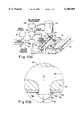
- FIG. 1(a)is a drawing of an ink transfer system utilizing a printhead which is capable of producing a drop of controlled volume.
- An image source 10may be raster image data from a scanner or computer, or outline image data in the form of a page description language, or other forms of digital image representation. This image data is converted by an image processing unit 12 to a map of the thermal activation necessary to provide the proper volume of ink for each pixel. This map is then transferred to image memory.
- Heater control circuits 14read data from the image memory and apply time-varying or multiple electrical pulses to selected nozzle heaters that are part of a printhead 16 with backup platen 21.
- Recording medium 18is moved relative to printhead 16 by a paper transport roller 20, which is electronically controlled by a paper transport control system 22, which in turn is controlled by a microcontroller 24.
- Microcontroller 24also controls an ink pressure regulator 26, which maintains a constant ink pressure in an ink reservoir 28 for supply to the printhead through an ink connection tube 29 and an ink channel assembly 30.
- Ink channel assembly 30may also serve the function of holding the printhead rigidly in place, and of correcting warp in the printhead.
- the ink pressurecan be very accurately generated and controlled by situating the top surface of the ink in reservoir 28 an appropriate distance above printhead 16. This ink level can be regulated by a simple float valve (not shown).
- the inkis distributed to the back surface of printhead 16 by an ink channel device 30.
- the inkpreferably flows through slots and/or holes etched through the silicon substrate of printhead 16 to the front surface, where the nozzles and heaters are situated.
- FIG. 1(b)is a detail enlargement of a cross-sectional view of a single nozzle tip of the drop-on-demand ink jet printhead 16 according to a preferred embodiment of the present invention.
- An ink delivery channel 40, along with a plurality of nozzle bores 46are etched in a substrate 42, which is silicon in this example.
- the delivery channel 40 and nozzle bore 46were formed by anisotropic wet etching of silicon, using a p + etch stop layer to form the shape of nozzle bore 46.
- Ink 70 in delivery channel 40is pressurized above atmospheric pressure, and forms a meniscus 60 which protrudes somewhat above nozzle rim 54, at a point where the force of surface tension, which tends to hold the drop in, balances the force of the ink pressure, which tends to push the drop out.
- the nozzleis of cylindrical form, with a heater 50 forming an annulus.
- the heaterwas made of polysilicon doped at a level of about thirty ohms/square, although other resistive heater material could be used.
- Nozzle rim 54is formed on top of heater 50 to provide a contact point for meniscus 60.
- the width of the nozzle rim in this examplewas 0.6 ⁇ m to 0.8 ⁇ m.
- Heater 50is separated from substrate 42 by thermal and electrical insulating layers 56 to minimize heat loss to the substrate.
- the layers in contact with the inkcan be passivated with a thin film layer 64 for protection, and can also include a layer to improve wetting of the nozzle with the ink in order to improve refill time.
- the printhead surfacecan be coated with a hydrophobizing layer 68 to prevent accidental spread of the ink across the front of the printhead.
- the top of nozzle rim 54may also be coated with a protective layer which could be either hydrophobic or hydrophilic.
- the ink pressureIn the quiescent state (with no ink drop selected), the ink pressure is insufficient to overcome the ink surface tension and eject a drop.
- the ink pressure for optimal operationwill depend mainly on the nozzle diameter, surface properties (such as the degree of hydrophobicity) of nozzle bore 46 and rim 54 of the nozzle, surface tension of the ink, and the power and temporal profile of the heater pulse.
- the inkhas a surface tension decrease with temperature such that heat transferred from the heater to the ink after application of an electrothermal pulse will result in the expansion of poised meniscus 60.
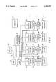
- FIG. 2illustrates the ink delivery system of a preferred embodiment of the present invention.
- Microcontroller 24(also shown in FIG. 1(a)) is connected to a computer 72, a Read Only Memory (ROM) 74 a Random Access Memory (RAM) 76, display 100, and ink pressure regulator 26 that regulates the ink pressure in ink reservoirs 28.
- Microcontroller 24is also connected to four ink sensors 78-81 that detect predetermined characteristics of the inks in the ink reservoirs 82-85, respectively. Reservoirs 82-85 correspond to reservoir 28 of FIG. 1(a).
- Microcontroller 24is also connected to four ink sensors 86-89 that detect characteristics of the inks in ink connection tubes 90-93, corresponding to ink connection tube 29 of FIG.
- Microcontroller 24is further connected to the sensors (not shown) in the print heads for detecting the presence as well as the characteristics of the inks in the print heads.
- the ink jet printercan utilize multiple printheads 94-97, with each printhead connected to one ink reservoir.
- the ink typesinclude black, yellow, magenta, and cyan colors and can also include several inks within each color. For example, labels “magenta1" and “magenta2" in FIG. 2 can represent magenta inks at different colorant concentrations.
- Sensors 78-81 and 86-89can detect the existence and the colorant concentration in the ink by sensing a detectable label material in the ink.
- detectable label materialrefers herein to an ink ingredient that is added to the ink and is detectable by sensors 78-81 and 86-89 in the ink delivery system.
- concentration of the detectable label material to the concentration of the colorantis held as constant in the ink.
- the detectable label materialis, however, not required to perform any other functions in the printhead or on the receiver media. In other words, the ink can achieve desired print qualities without the assistance of the detectable label materials.
- One detectable label material which may be usedis fine magnetic particles of magnetite Fe 3 O 4 to produce a black magnetic ink when blended with black pigment and solvent(s).
- the magnetite particlescan be refined in procedures as disclosed in U.S. Pat. No. 4,405,370.
- the concentration of the magnetic particlesis predetermined during manufacture. Details of a black pigmented ink containing a magnetic label material, e.g., is disclosed in commonly assigned, co-pending U.S. patent application Ser. No. 08/846,693 filed concurrently herewith.
- Magnetic inksexist in many other colors, and may be used in accordance with the present invention. Details of preparation of colored magnetic inks can be found in U.S. Pat. No. 5,506,079.
- the label materialsdo not affect the performance of the inks.
- the pigment inksoften comprise pigment particles smaller than 100 nm in average diameter, which is reported, for example, in "Novel Black Pigment for Ink Jet Ink Applications" by J. E. Johnson and J. A. Belmont, p. 226, in Recent Progress In Ink Jet Technologies, published by Society for Imaging Science and Technology.
- the magnetic particles used as the ink label materialsit is therefore desirable for the magnetic particles used as the ink label materials to be smaller than the average diameter of the pigment particles.
- the magnetic particlesare no longer permanent, for lengths smaller than 100 nm CrO 2 /CoFe, 50 nm Metal Particle, 30 nm BaFe because the particles become unstable due to thermal fluctuations.
- the preferred magnetic particle for the inkis Barium Ferrite (BaFeO), because of its small particle size, corrosion resistance, high curie temperature, and high anisotropy field. Small particle size is desirable to avoid kogation in the ink jet printhead. Corrosion resistance is necessary to insure the particles will remain magnetic after long periods of time in water or solvent based inks. High curie temperature and high anisotropy field decrease the lower limit on the size of particles which can be detected by the infield detector system of the invention. Even if some or all of the particles in the ink are smaller than the paramagnetic limit, the detector will still be able to detect them, because the applied field will align the magnetic moments of the particles.
- BaFeOBarium Ferrite
- a magnetic sensor for ink detectionincludes a permanent magnet and magnetic field sensors, with their measurement axes aligned perpendicular to the fixed field of the permanent magnet, such that no signal is produced from the large, fixed field of the permanent magnet.
- the sensordetects the fringing field from induced magnetization in objects or materials placed in proximity to the detector.
- This detectorutilizes a permanent horseshoe type magnet with two magnetic sensors placed symmetrically between the poles. The signals from the two sensors are subtracted to produce a net output signal. This significantly reduces noise from distant electromagnetic sources, temperature variations, and rotation of the detector in the earth's magnetic field.
- An object placed in front of the detectoris magnetized by the field of the permanent magnet, and the fringing field from this magnetization is detected by one or both of the magnetic sensors.
- the sensoris shown in FIG. 3.
- Two magnetic sensors 110 and 112are located between the poles of the magnet 114. These sensors can be of any type which are insensitive to magnetic field along one axis, including but not limited to hall effect sensors, magnetoresistive magnetometers, or flux gate magnetometers.
- Tube 116 containing ink 118is positioned close to one of the magnetic sensors 110,112. IF the ink contains magnetic particles, they will be oriented by the field of the magnet and the fringing field detected by the nearby sensor 110,112.
- the magnetic field lines 120 from the poles of magnet 114are schematically represented. Sensors 110 and 112 are aligned perpendicular to the field such that the signal from each is zero. The induced field 122 from magnetic ink 118 is shown, which results in a signal from sensor 110.
- the sensorsare recessed slightly into gap between the poles of the magnet, and oriented perpendicular tot he fields at their respective locations.
Landscapes
- Engineering & Computer Science (AREA)
- Quality & Reliability (AREA)
- Particle Formation And Scattering Control In Inkjet Printers (AREA)
Abstract
Description
__________________________________________________________________________Drop separation means Means Advantage Limitation __________________________________________________________________________ Electrostatic Can print on rough surfaces, Requires high voltage power attraction simple implementation supply AC electric field Higher field strength is Requires high voltage AC possible than electrostatic, power supply synchronized to operating margins can be drop ejection phase. Multiple increased, ink pressure drop phase operation is reduced, and dust difficult accumulation is reduced Proximity (printhead Very small spot sizes can be Requires print medium to be in close proximity to, achieved. Very low power very close to printhead surface, but not touching, dissipation. High drop unsuitable for rough print recording medium) position accuracy media, usually requires transfer roller or belt Transfer Proximity Very small spot sizes can be Not compact due to size of (printhead is in close achieved, very low power transfer roller or transfer belt proximity to a dissipation, high accuracy, transfer roller or belt can print on rough paper Proximity with Useful for hot melt inks using Requires print medium to be oscillating ink viscosity reduction drop very close to printhead surface, pressure selection method, reduces not suitable for rough print possibility of nozzle clogging, media. Requires ink pressure can use pigments instead of oscillation apparatus dyes Magnetic attraction Can print on rough surfaces. Requires uniform high Low power if permanent magnetic field strength, magnets are used requires magnetic ink __________________________________________________________________________
Claims (4)
Priority Applications (1)
| Application Number | Priority Date | Filing Date | Title |
|---|---|---|---|
| US08/958,274US6106089A (en) | 1997-04-30 | 1997-10-27 | Magnetic sensor for ink detection |
Applications Claiming Priority (3)
| Application Number | Priority Date | Filing Date | Title |
|---|---|---|---|
| US84692397A | 1997-04-30 | 1997-04-30 | |
| US08/846,693US5792380A (en) | 1997-04-30 | 1997-04-30 | Ink jet printing ink composition with detectable label material |
| US08/958,274US6106089A (en) | 1997-04-30 | 1997-10-27 | Magnetic sensor for ink detection |
Related Parent Applications (1)
| Application Number | Title | Priority Date | Filing Date |
|---|---|---|---|
| US84692397AContinuation-In-Part | 1997-04-30 | 1997-04-30 |
Publications (1)
| Publication Number | Publication Date |
|---|---|
| US6106089Atrue US6106089A (en) | 2000-08-22 |
Family
ID=27126663
Family Applications (1)
| Application Number | Title | Priority Date | Filing Date |
|---|---|---|---|
| US08/958,274Expired - LifetimeUS6106089A (en) | 1997-04-30 | 1997-10-27 | Magnetic sensor for ink detection |
Country Status (1)
| Country | Link |
|---|---|
| US (1) | US6106089A (en) |
Cited By (27)
| Publication number | Priority date | Publication date | Assignee | Title |
|---|---|---|---|---|
| US20030021524A1 (en)* | 2001-01-16 | 2003-01-30 | Dean David M. | Transparent paramagnetic polymer |
| US20030047100A1 (en)* | 2000-04-11 | 2003-03-13 | Stephen Brown | Method for continuously checking the production of security printing machines, application of said method and device for performing the method |
| US6612680B1 (en) | 2002-06-28 | 2003-09-02 | Lexmark International, Inc. | Method of imaging substance depletion detection for an imaging device |
| US6626513B2 (en) | 2001-07-18 | 2003-09-30 | Lexmark International, Inc. | Ink detection circuit and sensor for an ink jet printer |
| US20040079724A1 (en)* | 1998-09-09 | 2004-04-29 | Silverbrook Research Pty Ltd | Method of fabricating a fluid ejection device using a planarizing step |
| US20040094506A1 (en)* | 1998-10-16 | 2004-05-20 | Silverbrook Research Pty Ltd | Method of fabricating an inkjet printhead chip having laminated actuators |
| US20040246305A1 (en)* | 1998-10-16 | 2004-12-09 | Kia Silverbrook | Inkjet printhead having thermal bend actuator heating element electrically isolated from nozzle chamber ink |
| US20040263551A1 (en)* | 1998-10-16 | 2004-12-30 | Kia Silverbrook | Method and apparatus for firing ink from a plurality of nozzles on a printhead |
| US20050037532A1 (en)* | 1998-10-16 | 2005-02-17 | Kia Silverbrook | Method of fabricating a micro-electromechanical actuator that includes drive circuitry |
| US20050052497A1 (en)* | 1998-10-16 | 2005-03-10 | Kia Silverbrook | Pagewidth Inkjet printhead assembly with actuator drive circuitry |
| US20050093934A1 (en)* | 1998-10-16 | 2005-05-05 | Kia Silverbrook | Printer assembly and nozzle arrangement |
| US20050099466A1 (en)* | 1998-10-16 | 2005-05-12 | Kia Silverbrook | Printhead wafer with individual ink feed to each nozzle |
| US20050156984A1 (en)* | 2004-01-21 | 2005-07-21 | Fuji Photo Film Co., Ltd. | Inkjet recording apparatus and ink determination method |
| US20050231560A1 (en)* | 1999-10-15 | 2005-10-20 | Silverbrook Research Pty Ltd | Micro-electromechanical liquid ejection device |
| US20050237257A1 (en)* | 2004-04-26 | 2005-10-27 | Kin-Lu Wong | Antenna |
| US20050270335A1 (en)* | 1998-10-16 | 2005-12-08 | Silverbrook Research Pty Ltd | Method of fabricating a micro-electromechanical actuating mechanism |
| US20050279090A1 (en)* | 1998-09-09 | 2005-12-22 | Silverbrook Research Pty Ltd | Micro-electromechanical integrated circuit device with laminated actuators |
| US20060098047A1 (en)* | 1998-10-16 | 2006-05-11 | Silverbrook Research Pty Ltd. | Pagewidth inkjet printhead assembly with longitudinally extending sets of nozzles |
| US20060119661A1 (en)* | 1999-10-19 | 2006-06-08 | Silverbrook Research Pty Ltd | Nozzle arrangement |
| US20070081187A1 (en)* | 1998-11-09 | 2007-04-12 | Silverbrook Research Pty Ltd | Mobile telephone with printer and print media dispenser |
| US7237874B2 (en) | 2000-06-30 | 2007-07-03 | Silverbrook Research Pty Ltd | Inkjet printhead with grouped nozzles and a nozzle guard |
| US20070176968A1 (en)* | 1998-10-16 | 2007-08-02 | Silverbrook Research Pty Ltd | Pagewidth printhead having small print zone |
| US20070182785A1 (en)* | 1998-10-16 | 2007-08-09 | Silverbrook Research Pty Ltd | Inkjet Printhead Incorporating Interleaved Actuator Tails |
| US20080094432A1 (en)* | 1998-10-16 | 2008-04-24 | Silverbrook Research Pty Ltd | High nozzle density printhead ejecting low drop volumes |
| US20090237433A1 (en)* | 1998-10-16 | 2009-09-24 | Silverbrook Research Pty Ltd | Printhead Integrated Circuit With Low Drive Transistor To Nozzle Area Ratio |
| CN112792357A (en)* | 2020-12-17 | 2021-05-14 | 杭州德迪智能科技有限公司 | 3D printing equipment |
| US11055038B2 (en) | 2018-01-31 | 2021-07-06 | Hewlett-Packard Development Company, L.P. | Print substance end-of-life predictions |
Citations (18)
| Publication number | Priority date | Publication date | Assignee | Title |
|---|---|---|---|---|
| US3946398A (en)* | 1970-06-29 | 1976-03-23 | Silonics, Inc. | Method and apparatus for recording with writing fluids and drop projection means therefor |
| GB2007162A (en)* | 1977-10-03 | 1979-05-16 | Canon Kk | Liquid jet recording process and apparatus therefor |
| US4166277A (en)* | 1977-10-25 | 1979-08-28 | Northern Telecom Limited | Electrostatic ink ejection printing head |
| US4275290A (en)* | 1978-05-08 | 1981-06-23 | Northern Telecom Limited | Thermally activated liquid ink printing |
| US4405370A (en)* | 1980-05-20 | 1983-09-20 | Matsushita Electric Industrial Co., Ltd. | Magnetic ink refining method |
| US4490728A (en)* | 1981-08-14 | 1984-12-25 | Hewlett-Packard Company | Thermal ink jet printer |
| US4751531A (en)* | 1986-03-27 | 1988-06-14 | Fuji Xerox Co., Ltd. | Thermal-electrostatic ink jet recording apparatus |
| US4963939A (en)* | 1986-09-24 | 1990-10-16 | Mita Industrial Co., Ltd. | Cartridge discriminating system |
| US5250957A (en)* | 1991-07-29 | 1993-10-05 | Alps Electric Co., Ltd. | Method of detecting an ink residual quantity in an ink jet printer |
| JPH06348389A (en)* | 1993-06-02 | 1994-12-22 | Yashima Denki Co Ltd | Pen |
| US5506079A (en)* | 1994-02-28 | 1996-04-09 | Ricoh Company, Ltd. | Magnetic composition, magnetic toner and ink containing the magnetic composition |
| US5541632A (en)* | 1992-08-12 | 1996-07-30 | Hewlett-Packard Company | Ink pressure regulator for a thermal ink jet printer |
| US5557310A (en)* | 1989-10-20 | 1996-09-17 | Canon Kabushiki Kaisha | Ink container with ring-shaped ink absorbing member |
| EP0745482A2 (en)* | 1995-05-31 | 1996-12-04 | Hewlett-Packard Company | Continuous refill of spring bag reservoir in an ink-jet printer/plotter |
| EP0745481A2 (en)* | 1995-05-31 | 1996-12-04 | Hewlett-Packard Company | Ink-jet swath printer with auxiliary ink reservoir |
| US5599578A (en)* | 1986-04-30 | 1997-02-04 | Butland; Charles L. | Technique for labeling an object for its identification and/or verification |
| US5610518A (en)* | 1995-03-16 | 1997-03-11 | Eastman Kodak Company | Method and apparatus for detecting small magnetizable particles and flaws in nonmagnetic conductors |
| US5682184A (en)* | 1995-12-18 | 1997-10-28 | Xerox Corporation | System for sensing ink level and type of ink for an ink jet printer |
- 1997
- 1997-10-27USUS08/958,274patent/US6106089A/ennot_activeExpired - Lifetime
Patent Citations (18)
| Publication number | Priority date | Publication date | Assignee | Title |
|---|---|---|---|---|
| US3946398A (en)* | 1970-06-29 | 1976-03-23 | Silonics, Inc. | Method and apparatus for recording with writing fluids and drop projection means therefor |
| GB2007162A (en)* | 1977-10-03 | 1979-05-16 | Canon Kk | Liquid jet recording process and apparatus therefor |
| US4166277A (en)* | 1977-10-25 | 1979-08-28 | Northern Telecom Limited | Electrostatic ink ejection printing head |
| US4275290A (en)* | 1978-05-08 | 1981-06-23 | Northern Telecom Limited | Thermally activated liquid ink printing |
| US4405370A (en)* | 1980-05-20 | 1983-09-20 | Matsushita Electric Industrial Co., Ltd. | Magnetic ink refining method |
| US4490728A (en)* | 1981-08-14 | 1984-12-25 | Hewlett-Packard Company | Thermal ink jet printer |
| US4751531A (en)* | 1986-03-27 | 1988-06-14 | Fuji Xerox Co., Ltd. | Thermal-electrostatic ink jet recording apparatus |
| US5599578A (en)* | 1986-04-30 | 1997-02-04 | Butland; Charles L. | Technique for labeling an object for its identification and/or verification |
| US4963939A (en)* | 1986-09-24 | 1990-10-16 | Mita Industrial Co., Ltd. | Cartridge discriminating system |
| US5557310A (en)* | 1989-10-20 | 1996-09-17 | Canon Kabushiki Kaisha | Ink container with ring-shaped ink absorbing member |
| US5250957A (en)* | 1991-07-29 | 1993-10-05 | Alps Electric Co., Ltd. | Method of detecting an ink residual quantity in an ink jet printer |
| US5541632A (en)* | 1992-08-12 | 1996-07-30 | Hewlett-Packard Company | Ink pressure regulator for a thermal ink jet printer |
| JPH06348389A (en)* | 1993-06-02 | 1994-12-22 | Yashima Denki Co Ltd | Pen |
| US5506079A (en)* | 1994-02-28 | 1996-04-09 | Ricoh Company, Ltd. | Magnetic composition, magnetic toner and ink containing the magnetic composition |
| US5610518A (en)* | 1995-03-16 | 1997-03-11 | Eastman Kodak Company | Method and apparatus for detecting small magnetizable particles and flaws in nonmagnetic conductors |
| EP0745482A2 (en)* | 1995-05-31 | 1996-12-04 | Hewlett-Packard Company | Continuous refill of spring bag reservoir in an ink-jet printer/plotter |
| EP0745481A2 (en)* | 1995-05-31 | 1996-12-04 | Hewlett-Packard Company | Ink-jet swath printer with auxiliary ink reservoir |
| US5682184A (en)* | 1995-12-18 | 1997-10-28 | Xerox Corporation | System for sensing ink level and type of ink for an ink jet printer |
Non-Patent Citations (2)
| Title |
|---|
| Johnson, J.E. and Belmont, J.A., Novel Black Pigment for Ink Jet Ink Applications, Recent Progress in Ink Jet Technologies , Society for Imaging Science and Technology, pp. 226 229.* |
| Johnson, J.E. and Belmont, J.A., Novel Black Pigment for Ink Jet Ink Applications, Recent Progress in Ink-Jet Technologies, Society for Imaging Science and Technology, pp. 226-229. |
Cited By (245)
| Publication number | Priority date | Publication date | Assignee | Title |
|---|---|---|---|---|
| US7597435B2 (en) | 1997-07-15 | 2009-10-06 | Silverbrook Research Pty Ltd | Ink supply unit for an ink jet printer |
| US20080129809A1 (en)* | 1997-07-15 | 2008-06-05 | Silverbrook Research Pty Ltd | Ink Supply Unit For An Ink Jet Printer |
| US20040119784A1 (en)* | 1998-09-09 | 2004-06-24 | Silverbrook Research Pty Ltd | Printhead configuration incorporating a nozzle arrangement layout |
| US20090244194A1 (en)* | 1998-09-09 | 2009-10-01 | Silverbrook Research Pty Ltd | Micro-Electromechanical Integrated Circuit Device With Laminated Actuators |
| US20040079724A1 (en)* | 1998-09-09 | 2004-04-29 | Silverbrook Research Pty Ltd | Method of fabricating a fluid ejection device using a planarizing step |
| US20040118808A1 (en)* | 1998-09-09 | 2004-06-24 | Silverbrook Research Pty Ltd | Method of fabricating a micro-electromechanical device having a laminated actuator |
| US20050189317A1 (en)* | 1998-09-09 | 2005-09-01 | Kia Silverbrook | Method of fabricating inkjet nozzle |
| US20040113983A1 (en)* | 1998-09-09 | 2004-06-17 | Silverbrook Research Pty Ltd | Micro-electromechanical fluid ejection device with control logic circuttry |
| US7380913B2 (en) | 1998-09-09 | 2008-06-03 | Silverbrook Research Pty Ltd | Ink jet printer nozzle assembly with micro-electromechanical paddles |
| US20070211112A1 (en)* | 1998-09-09 | 2007-09-13 | Silverbrook Research Pty Ltd | Ink jet printer nozzle assembly with micro-electromechanical paddles |
| US7014785B2 (en) | 1998-09-09 | 2006-03-21 | Silverbrook Research Pty Ltd | Method of fabricating inkjet nozzle |
| US20050279090A1 (en)* | 1998-09-09 | 2005-12-22 | Silverbrook Research Pty Ltd | Micro-electromechanical integrated circuit device with laminated actuators |
| US6832828B2 (en) | 1998-09-09 | 2004-12-21 | Silverbrook Research Pty Ltd | Micro-electromechanical fluid ejection device with control logic circuitry |
| US20050189316A1 (en)* | 1998-09-09 | 2005-09-01 | Kia Silverbrook | Method of fabricating micro-electromechanical inkjet nozzle |
| US20080246817A1 (en)* | 1998-10-16 | 2008-10-09 | Silverbrook Research Pty Ltd | Nozzle Arrangement With Control Logic Architecture For An Ink Jet Printhead |
| US8066355B2 (en) | 1998-10-16 | 2011-11-29 | Silverbrook Research Pty Ltd | Compact nozzle assembly of an inkjet printhead |
| US6860590B2 (en) | 1998-10-16 | 2005-03-01 | Silverbrook Research Pty Ltd | Printhead configuration incorporating a nozzle arrangement layout |
| US20050052497A1 (en)* | 1998-10-16 | 2005-03-10 | Kia Silverbrook | Pagewidth Inkjet printhead assembly with actuator drive circuitry |
| US20050093934A1 (en)* | 1998-10-16 | 2005-05-05 | Kia Silverbrook | Printer assembly and nozzle arrangement |
| US20050099466A1 (en)* | 1998-10-16 | 2005-05-12 | Kia Silverbrook | Printhead wafer with individual ink feed to each nozzle |
| US20050099465A1 (en)* | 1998-10-16 | 2005-05-12 | Kia Silverbrook | Printhead temperature feedback method for a microelectromechanical ink jet printhead |
| US20050109730A1 (en)* | 1998-10-16 | 2005-05-26 | Kia Silverbrook | Printhead wafer etched from opposing sides |
| US6902255B1 (en)* | 1998-10-16 | 2005-06-07 | Silverbrook Research Pty Ltd | Inkjet printers |
| US6905620B2 (en) | 1998-10-16 | 2005-06-14 | Silverbrook Research Pty Ltd | Method of fabricating a micro-electromechanical device having a laminated actuator |
| US20050134649A1 (en)* | 1998-10-16 | 2005-06-23 | Kia Silverbrook | Printhead chip with nozzle arrangement for color printing |
| US20050134648A1 (en)* | 1998-10-16 | 2005-06-23 | Kia Silverbrook | Printhead configuration having acutely aligned nozzle actuators |
| US20050140726A1 (en)* | 1998-10-16 | 2005-06-30 | Kia Silverbrook | Nozzle arrangement including an actuator |
| US20050144781A1 (en)* | 1998-10-16 | 2005-07-07 | Kia Silverbrook | Fabricating an inkjet printhead with grouped nozzles |
| US20050146566A1 (en)* | 1998-10-16 | 2005-07-07 | Kia Silverbrook | Inkjet printhead that incorporates feed back sense lines |
| US20050157042A1 (en)* | 1998-10-16 | 2005-07-21 | Kia Silverbrook | Printhead |
| US8336990B2 (en) | 1998-10-16 | 2012-12-25 | Zamtec Limited | Ink supply unit for printhead of inkjet printer |
| US8087757B2 (en) | 1998-10-16 | 2012-01-03 | Silverbrook Research Pty Ltd | Energy control of a nozzle of an inkjet printhead |
| US20080303871A1 (en)* | 1998-10-16 | 2008-12-11 | Silverbrook Research Pty Ltd | Nozzle assembly for an inkjet printer for ejecting a low volume droplet |
| US8061795B2 (en) | 1998-10-16 | 2011-11-22 | Silverbrook Research Pty Ltd | Nozzle assembly of an inkjet printhead |
| US20040263551A1 (en)* | 1998-10-16 | 2004-12-30 | Kia Silverbrook | Method and apparatus for firing ink from a plurality of nozzles on a printhead |
| US20050225601A1 (en)* | 1998-10-16 | 2005-10-13 | Silverbrook Research Pty Ltd. | Inkjet printhead apparatus |
| US20050225604A1 (en)* | 1998-10-16 | 2005-10-13 | Silverbrook Research Pty Ltd | Method of forming a nozzle rim |
| US8057014B2 (en) | 1998-10-16 | 2011-11-15 | Silverbrook Research Pty Ltd | Nozzle assembly for an inkjet printhead |
| US8047633B2 (en) | 1998-10-16 | 2011-11-01 | Silverbrook Research Pty Ltd | Control of a nozzle of an inkjet printhead |
| US20050243134A1 (en)* | 1998-10-16 | 2005-11-03 | Silverbrook Research Pty Ltd | Printhead integrated circuit comprising thermal bend actuator |
| US20050253897A1 (en)* | 1998-10-16 | 2005-11-17 | Silverbrook Research Pty Ltd | Inkjet printhead having grouped inkjet nozzles |
| US20050270335A1 (en)* | 1998-10-16 | 2005-12-08 | Silverbrook Research Pty Ltd | Method of fabricating a micro-electromechanical actuating mechanism |
| US20040246305A1 (en)* | 1998-10-16 | 2004-12-09 | Kia Silverbrook | Inkjet printhead having thermal bend actuator heating element electrically isolated from nozzle chamber ink |
| US6998278B2 (en) | 1998-10-16 | 2006-02-14 | Silverbrook Research Pty Ltd | Method of fabricating a micro-electromechanical actuator that includes drive circuitry |
| US8025355B2 (en) | 1998-10-16 | 2011-09-27 | Silverbrook Research Pty Ltd | Printer system for providing pre-heat signal to printhead |
| US7028474B2 (en) | 1998-10-16 | 2006-04-18 | Silverbook Research Pty Ltd | Micro-electromechanical actuator with control logic circuitry |
| US20060098047A1 (en)* | 1998-10-16 | 2006-05-11 | Silverbrook Research Pty Ltd. | Pagewidth inkjet printhead assembly with longitudinally extending sets of nozzles |
| US7048868B2 (en) | 1998-10-16 | 2006-05-23 | Silverbrook Reseach Pty Ltd | Method of fabricating micro-electromechanical inkjet nozzle |
| US8011757B2 (en) | 1998-10-16 | 2011-09-06 | Silverbrook Research Pty Ltd | Inkjet printhead with interleaved drive transistors |
| US20060152551A1 (en)* | 1998-10-16 | 2006-07-13 | Silverbrook Research Pty Ltd | Printhead integrated circuit for a pagewidth inkjet printhead |
| US7080895B2 (en) | 1998-10-16 | 2006-07-25 | Silverbrook Research Pty Ltd | Inkjet printhead apparatus |
| US7111924B2 (en) | 1998-10-16 | 2006-09-26 | Silverbrook Research Pty Ltd | Inkjet printhead having thermal bend actuator heating element electrically isolated from nozzle chamber ink |
| US20060227156A1 (en)* | 1998-10-16 | 2006-10-12 | Silverbrook Research Pty Ltd | Inkjet printhead having a pre-determined array of inkjet nozzle assemblies |
| US7132056B2 (en) | 1998-10-16 | 2006-11-07 | Silverbrook Research Pty Ltd | Method of fabricating a fluid ejection device using a planarizing step |
| US20060250448A1 (en)* | 1998-10-16 | 2006-11-09 | Silverbrook Research Pty Ltd | Inkjet printhead having ink flow preventing actuators |
| US7134740B2 (en) | 1998-10-16 | 2006-11-14 | Silverbrook Research Pty Ltd | Pagewidth inkjet printhead assembly with actuator drive circuitry |
| US20060268048A1 (en)* | 1998-10-16 | 2006-11-30 | Silverbrook Research Pty Ltd | Inkjet printhead integrated circuit with optimized trace orientation |
| US20060268064A1 (en)* | 1998-10-16 | 2006-11-30 | Silverbrook Research Pty Ltd | Pagewidth printhead assembly with flexible tab film for supplying power and data to printhead integrated circuits |
| US7144519B2 (en) | 1998-10-16 | 2006-12-05 | Silverbrook Research Pty Ltd | Method of fabricating an inkjet printhead chip having laminated actuators |
| US20060274119A1 (en)* | 1998-10-16 | 2006-12-07 | Silverbrook Research Pty Ltd | Ink ejection nozzle with a thermal bend actuator |
| US20060274121A1 (en)* | 1998-10-16 | 2006-12-07 | Silverbrook Research Pty Ltd | Inkjet nozzle assembly with resistive heating actuator |
| US7147304B2 (en) | 1998-10-16 | 2006-12-12 | Silverbrook Research Pty Ltd | Pagewidth inkjet printhead assembly with longitudinally extending sets of nozzles |
| US7152944B2 (en) | 1998-10-16 | 2006-12-26 | Silverbrook Research Pty Ltd | Ink jet printhead assembly with an ink distribution manifold |
| US7159968B2 (en) | 1998-10-16 | 2007-01-09 | Silverbrook Research Pty Ltd | Printhead integrated circuit comprising thermal bend actuator |
| US20070008386A1 (en)* | 1998-10-16 | 2007-01-11 | Silverbrook Research Pty Ltd | Nozzle arrangement for an inkjet printhead having a thermal actuator and paddle |
| US20070030315A1 (en)* | 1998-10-16 | 2007-02-08 | Silverbrook Research Pty Ltd. | Printhead with drive transistors and corresponding ink ejection actuators |
| US20070030321A1 (en)* | 1998-10-16 | 2007-02-08 | Silverbrook Research Pty Ltd | Ink supply unit for an ink jet printer |
| US7178899B2 (en) | 1998-10-16 | 2007-02-20 | Silverbrook Research Pty Ltd | Printhead integrated circuit for a pagewidth inkjet printhead |
| US7976131B2 (en) | 1998-10-16 | 2011-07-12 | Silverbrook Research Pty Ltd | Printhead integrated circuit comprising resistive elements spaced apart from substrate |
| US7182437B2 (en) | 1998-10-16 | 2007-02-27 | Silverbrook Research Pty Ltd | Inkjet printhead having ink flow preventing actuators |
| US7188935B2 (en) | 1998-10-16 | 2007-03-13 | Silverbrook Research Pty Ltd | Printhead wafer with individual ink feed to each nozzle |
| US20070070133A1 (en)* | 1998-10-16 | 2007-03-29 | Silverbrook Research Pty Ltd | Ink supply unit for a printhead in an inkjet printer |
| US7198346B2 (en) | 1998-10-16 | 2007-04-03 | Silverbrook Research Pty Ltd | Inkjet printhead that incorporates feed back sense lines |
| US7971972B2 (en) | 1998-10-16 | 2011-07-05 | Silverbrook Research Pty Ltd | Nozzle arrangement with fully static CMOS control logic architecture |
| US20070081031A1 (en)* | 1998-10-16 | 2007-04-12 | Silverbrook Research Pty Ltd | Pagewidth printhead having sealed inkjet actuators |
| US7207656B2 (en) | 1998-10-16 | 2007-04-24 | Silverbrook Research Pty Ltd | Printhead configuration having acutely aligned nozzle actuators |
| US7210764B2 (en) | 1998-10-16 | 2007-05-01 | Silverbrook Research Pty Ltd | Printhead with drive transistors and corresponding ink ejection actuators |
| US20070109345A1 (en)* | 1998-10-16 | 2007-05-17 | Silverbrook Research Pty Ltd | Nozzle arrangement for an inkjet printhead with associated actuator drive ciircuitry |
| US7219427B2 (en) | 1998-10-16 | 2007-05-22 | Silverbrook Research Pty Ltd | Fabricating an inkjet printhead with grouped nozzles |
| US20070115316A1 (en)* | 1998-10-16 | 2007-05-24 | Silverbrook Research Pty Ltd | Inkjet printhead with a wafer assembly having an array of nozzle arrangments |
| US7229154B2 (en) | 1998-10-16 | 2007-06-12 | Silverbrook Research Pty Ltd | Ink ejection nozzle with a thermal bend actuator |
| US20070146432A1 (en)* | 1998-10-16 | 2007-06-28 | Silverbrook Research Pty Ltd | Inkjet printhead with spillage pits |
| US7971967B2 (en) | 1998-10-16 | 2011-07-05 | Silverbrook Research Pty Ltd | Nozzle arrangement with actuator slot protection barrier |
| US20070176971A1 (en)* | 1998-10-16 | 2007-08-02 | Silverbrook Research Pty Ltd | Web printer with straight print media Path |
| US20070176968A1 (en)* | 1998-10-16 | 2007-08-02 | Silverbrook Research Pty Ltd | Pagewidth printhead having small print zone |
| US20070176967A1 (en)* | 1998-10-16 | 2007-08-02 | Silverbrook Research Pty Ltd | Photo printer for printing 6" x 4" photos |
| US20070182785A1 (en)* | 1998-10-16 | 2007-08-09 | Silverbrook Research Pty Ltd | Inkjet Printhead Incorporating Interleaved Actuator Tails |
| US20070182784A1 (en)* | 1998-10-16 | 2007-08-09 | Silverbrook Research Pty Ltd | Ink ejection nozzle arrangement with layered actuator mechanism |
| US20070188570A1 (en)* | 1998-10-16 | 2007-08-16 | Silverbrook Research Pty Ltd | Ink supply arrangement incorporating baffles in an ink distribution molding |
| US20070188554A1 (en)* | 1998-10-16 | 2007-08-16 | Silverbrook Research Pty Ltd | Inkjet printhead with pairs of ink spread restriction pits |
| US20070188557A1 (en)* | 1998-10-16 | 2007-08-16 | Silverbrook Research Pty Ltd | Printer comprising small area print chips forming a pagewidth printhead |
| US20070211102A1 (en)* | 1998-10-16 | 2007-09-13 | Silverbrook Research Pty Ltd | Ink Supply Arrangement Incorporating Sets of Passages for Carrying Respective Types of Ink |
| US7971975B2 (en) | 1998-10-16 | 2011-07-05 | Silverbrook Research Pty Ltd | Inkjet printhead comprising actuator spaced apart from substrate |
| US20070222819A1 (en)* | 1998-10-16 | 2007-09-27 | Silverbrook Research Pty Ltd | Printhead with small drive transistor to nozzle area ratio |
| US20070222807A1 (en)* | 1998-10-16 | 2007-09-27 | Silverbrook Research Pty Ltd | Printhead and method for contolling print quality using printhead temperature |
| US20070222821A1 (en)* | 1998-10-16 | 2007-09-27 | Silverbrook Research Pty Ltd | Signaling method for printhead |
| US7284836B2 (en) | 1998-10-16 | 2007-10-23 | Silverbrook Research Pty Ltd | Nozzle arrangement including an actuator |
| US7967422B2 (en) | 1998-10-16 | 2011-06-28 | Silverbrook Research Pty Ltd | Inkjet nozzle assembly having resistive element spaced apart from substrate |
| US20080012923A1 (en)* | 1998-10-16 | 2008-01-17 | Silverbrook Research Pty Ltd | Printer incorporating a print roll unit supplying ink to a baffled ink supply unit |
| US7322680B2 (en) | 1998-10-16 | 2008-01-29 | Silverbrook Research Pty Ltd | Printer assembly and nozzle arrangement |
| US20080278559A1 (en)* | 1998-10-16 | 2008-11-13 | Silverbrook Research Pty Ltd | Printer assembly with a controller for maintaining a printhead at an equilibrium temperature |
| US7350901B2 (en) | 1998-10-16 | 2008-04-01 | Silverbrook Research Pty Ltd | Ink supply unit for an ink jet printer |
| US7350906B2 (en) | 1998-10-16 | 2008-04-01 | Silverbrook Research Pty Ltd | Ink supply arrangement incorporating sets of passages for carrying respective types of ink |
| US20080079760A1 (en)* | 1998-10-16 | 2008-04-03 | Silverbrook Research Pry Ltd | Printhead with variable nozzle firing sequence |
| US20080094432A1 (en)* | 1998-10-16 | 2008-04-24 | Silverbrook Research Pty Ltd | High nozzle density printhead ejecting low drop volumes |
| US7370942B2 (en) | 1998-10-16 | 2008-05-13 | Silverbrook Research Pty Ltd | Ink supply arrangement incorporating baffles in an ink distribution molding |
| US7380339B2 (en) | 1998-10-16 | 2008-06-03 | Silverbrook Research Pty Ltd | Method of manufacturing a printhead wafer etched from opposing sides |
| US7380906B2 (en) | 1998-10-16 | 2008-06-03 | Silverbrook Research Pty Ltd | Printhead |
| US7950771B2 (en) | 1998-10-16 | 2011-05-31 | Silverbrook Research Pty Ltd | Printhead nozzle arrangement with dual mode thermal actuator |
| US7946671B2 (en) | 1998-10-16 | 2011-05-24 | Silverbrook Research Pty Ltd | Inkjet printer for photographs |
| US7384131B2 (en) | 1998-10-16 | 2008-06-10 | Silverbrook Research Pty Ltd | Pagewidth printhead having small print zone |
| US7387368B2 (en) | 1998-10-16 | 2008-06-17 | Silverbrook Reseach Pty Ltd | Pagewidth printhead having sealed inkjet actuators |
| US7396108B2 (en) | 1998-10-16 | 2008-07-08 | Silverbrook Research Pty Ltd | Pagewidth printhead assembly with flexible tab film for supplying power and data to printhead integrated circuits |
| US7401895B2 (en) | 1998-10-16 | 2008-07-22 | Silverbrook Research Pty Ltd | Inkjet printhead integrated circuit with optimized trace orientation |
| US7416275B2 (en) | 1998-10-16 | 2008-08-26 | Silverbrook Research Pty Ltd | Printhead chip with nozzle arrangement for color printing |
| US20080204514A1 (en)* | 1998-10-16 | 2008-08-28 | Silverbrook Research Pty Ltd | Nozzle Arrangement Having An Actuator Slot Protection Barrier To Reduce Ink Wicking |
| US7419247B2 (en) | 1998-10-16 | 2008-09-02 | Silverbrook Research Pty Ltd | Printer comprising small area print chips forming a pagewidth printhead |
| US7419244B2 (en) | 1998-10-16 | 2008-09-02 | Silverbrook Research Pty Ltd | Ink ejection nozzle arrangement with layered actuator mechanism |
| US20080273059A1 (en)* | 1998-10-16 | 2008-11-06 | Silverbrook Research Pty Ltd | Nozzle assembly of an inkjet printhead |
| US20080211876A1 (en)* | 1998-10-16 | 2008-09-04 | Silverbrook Research Pty Ltd | Printhead For Use In Camera Photo-Printing |
| US20080211879A1 (en)* | 1998-10-16 | 2008-09-04 | Silverbrook Research Pty Ltd | Pagewidth inkjet printhead assembly with nozzle arrangements having actuator arms configured to be in thermal balance when in a quiescent state |
| US20080211877A1 (en)* | 1998-10-16 | 2008-09-04 | Silverbrook Research Pty Ltd | Inkjet Printhead Having Nozzle Arrangements With Ink Spreading Prevention Rims |
| US7938524B2 (en) | 1998-10-16 | 2011-05-10 | Silverbrook Research Pty Ltd | Ink supply unit for ink jet printer |
| US7441867B2 (en) | 1998-10-16 | 2008-10-28 | Silverbrook Research Pty Ltd | Inkjet printhead having a pre-determined array of inkjet nozzle assemblies |
| US7442317B2 (en)* | 1998-10-16 | 2008-10-28 | Silverbrook Research Pty Ltd | Method of forming a nozzle rim |
| US20080266361A1 (en)* | 1998-10-16 | 2008-10-30 | Silverbrook Research Pty Ltd | Energy control of a nozzle of an inkjet printhead |
| US20080266356A1 (en)* | 1998-10-16 | 2008-10-30 | Silverbrook Research Pty Ltd | Compact nozzle assembly of an inkjet printhead |
| US20080266341A1 (en)* | 1998-10-16 | 2008-10-30 | Silverbrook Research Pty Ltd | Control logic for an inkjet printhead |
| US7934799B2 (en) | 1998-10-16 | 2011-05-03 | Silverbrook Research Pty Ltd | Inkjet printer with low drop volume printhead |
| US7331101B2 (en) | 1998-10-16 | 2008-02-19 | Silverbrook Research Pty Ltd | Method of fabricating a micro-electromechanical actuating mechanism |
| US20050037532A1 (en)* | 1998-10-16 | 2005-02-17 | Kia Silverbrook | Method of fabricating a micro-electromechanical actuator that includes drive circuitry |
| US20080303866A1 (en)* | 1998-10-16 | 2008-12-11 | Silverbrook Research Pty Ltd | Nozzle assembly for an inkjet printer for ejecting a low speed droplet |
| US20080309696A1 (en)* | 1998-10-16 | 2008-12-18 | Silverbrook Research Pty Ltd | g of nozzles of a printhead of an inkjet printer |
| US20080309694A1 (en)* | 1998-10-16 | 2008-12-18 | Silverbrook Research Pty Ltd | Aperture of a nozzle assembly of an inkjet printer |
| US20080309699A1 (en)* | 1998-10-16 | 2008-12-18 | Silverbrook Research Pty Ltd | Low energy consumption nozzle assembly for an inkjet printer |
| US20080309693A1 (en)* | 1998-10-16 | 2008-12-18 | Silverbrook Research Pty Ltd | Nozzle assembly for ejecting small droplets |
| US20080309695A1 (en)* | 1998-10-16 | 2008-12-18 | Silverbrook Research Pty Ltd | Nozzle assembly for an inkjet printer having a short drive transistor channel |
| US20080309697A1 (en)* | 1998-10-16 | 2008-12-18 | Silverbrook Research Pty Ltd | Printhead of an inkjet printer having densely spaced nozzles |
| US20080309720A1 (en)* | 1998-10-16 | 2008-12-18 | Silverbrook Research Pty Ltd | Inkjet printer nozzle formed on a drive transistor and control logic |
| US20080309721A1 (en)* | 1998-10-16 | 2008-12-18 | Silverbrook Research Pty Ltd | Low voltage nozzle assembly for an inkjet printer |
| US20080309722A1 (en)* | 1998-10-16 | 2008-12-18 | Silverbrook Research Pty Ltd | Low pressure nozzle for an inkjet printer |
| US20080316271A1 (en)* | 1998-10-16 | 2008-12-25 | Silverbrook Research Pty Ltd | Nozzle arrangement for an inkjet printer with ink wicking reduction |
| US20080316241A1 (en)* | 1998-10-16 | 2008-12-25 | Silverbrook Research Pty Ltd | Nozzle assembly for an inkjet printhead |
| US20080316242A1 (en)* | 1998-10-16 | 2008-12-25 | Silverbrook Research Pty Ltd | Control Of A Nozzle Of An Inkjet Printhead |
| US20080316262A1 (en)* | 1998-10-16 | 2008-12-25 | Silverbrook Research Pty Ltd | Compact nozzle assembly for an inkjet printer |
| US20080316276A1 (en)* | 1998-10-16 | 2008-12-25 | Silverbrook Research Pty Ltd. | Printhead integrated circuit having an ink ejection member with a laminated structure |
| US20090002470A1 (en)* | 1998-10-16 | 2009-01-01 | Silverbrook Research Pty Ltd | Camera Printhead Assembly With Baffles To Retard Ink Acceleration |
| US7506966B2 (en) | 1998-10-16 | 2009-03-24 | Silverbrook Research Pty Ltd | Printer incorporating a print roll unit supplying ink to a baffled ink supply unit |
| US7517055B2 (en) | 1998-10-16 | 2009-04-14 | Silverbrook Research Pty Ltd | Nozzle arrangement for an inkjet printhead with associated actuator drive circuitry |
| US7524032B2 (en) | 1998-10-16 | 2009-04-28 | Silverbrook Research Pty Ltd | Inkjet nozzle assembly with resistive heating actuator |
| US7524029B2 (en) | 1998-10-16 | 2009-04-28 | Silverbrook Research Pty Ltd | Inkjet printhead with pairs of ink spread restriction pits |
| US7537314B2 (en) | 1998-10-16 | 2009-05-26 | Silverbrook Research Pty Ltd | Inkjet printhead having nozzle arrangements with ink spreading prevention rims |
| US7549726B2 (en) | 1998-10-16 | 2009-06-23 | Silverbrook Research Pty Ltd | Inkjet printhead with a wafer assembly having an array of nozzle arrangements |
| US7556353B2 (en) | 1998-10-16 | 2009-07-07 | Silverbrook Research Pty Ltd | Printhead with small drive transistor to nozzle area ratio |
| US7556358B2 (en) | 1998-10-16 | 2009-07-07 | Silverbrook Research Pty Ltd | Micro-electromechanical integrated circuit device with laminated actuators |
| US7556352B2 (en) | 1998-10-16 | 2009-07-07 | Silverbrook Research Pty Ltd | Inject printhead with outwarldy extending actuator tails |
| US7556361B2 (en) | 1998-10-16 | 2009-07-07 | Silverbrook Research Pty Ltd | Ink supply unit having a cover unit for positioning tape automated bonded film |
| US7556351B2 (en) | 1998-10-16 | 2009-07-07 | Silverbrook Research Pty Ltd | Inkjet printhead with spillage pits |
| US7562962B2 (en) | 1998-10-16 | 2009-07-21 | Silverbrook Research Pty Ltd | Printhead for use in camera photo-printing |
| US7931351B2 (en) | 1998-10-16 | 2011-04-26 | Silverbrook Research Pty Ltd | Inkjet printhead and printhead nozzle arrangement |
| US7562963B2 (en) | 1998-10-16 | 2009-07-21 | Silverbrook Research Pty Ltd | Pagewidth inkjet printhead assembly with nozzle arrangements having actuator arms configured to be in thermal balance when in a quiescent state |
| US20090195598A1 (en)* | 1998-10-16 | 2009-08-06 | Silverbrook Research Pty Ltd | Inkjet Printhead With Shared Ink Spread Restriction Walls |
| US20090195614A1 (en)* | 1998-10-16 | 2009-08-06 | Silverbrook Research Pty Ltd | Inkjet Printhead Nozzle Arrangement With Actuator Arm Slot Protection Barrier |
| US20090201339A1 (en)* | 1998-10-16 | 2009-08-13 | Silverbrook Research Pty Ltd | Printhead Nozzle Having Shaped Heating Element |
| US7578569B2 (en) | 1998-10-16 | 2009-08-25 | Silverbrook Research Pty Ltd | Printhead with variable nozzle firing sequence |
| US20090213186A1 (en)* | 1998-10-16 | 2009-08-27 | Silvebrook Research Pty Ltd | Inkjet Printhead Having Plural Nozzle Arrangements Grouped In Pods |
| US7585047B2 (en) | 1998-10-16 | 2009-09-08 | Silverbrook Research Pty Ltd | Nozzle arrangement with control logic architecture for an ink jet printhead |
| US7591541B2 (en) | 1998-10-16 | 2009-09-22 | Silverbrook Research Pty Ltd | Nozzle arrangement having an actuator slot protection barrier to reduce ink wicking |
| US20090237433A1 (en)* | 1998-10-16 | 2009-09-24 | Silverbrook Research Pty Ltd | Printhead Integrated Circuit With Low Drive Transistor To Nozzle Area Ratio |
| US20090237450A1 (en)* | 1998-10-16 | 2009-09-24 | Silverbrook Research Pty Ltd | Inkjet Printhead and Printhead Nozzle Arrangement |
| US20090237461A1 (en)* | 1998-10-16 | 2009-09-24 | Silverbrook Research Pty Ltd | Ink ejection nozzle arrangement |
| US7918540B2 (en) | 1998-10-16 | 2011-04-05 | Silverbrook Research Pty Ltd | Microelectromechanical ink jet printhead with printhead temperature feedback |
| US20090244193A1 (en)* | 1998-10-16 | 2009-10-01 | Silverbrook Research Pty Ltd | Inkjet printhead and printhead nozzle arrangement |
| US20040094506A1 (en)* | 1998-10-16 | 2004-05-20 | Silverbrook Research Pty Ltd | Method of fabricating an inkjet printhead chip having laminated actuators |
| US20090256890A1 (en)* | 1998-10-16 | 2009-10-15 | Silverbrook Research Pty Ltd | Printhead Nozzle Arrangement With Dual Mode Thermal Actuator |
| US7611220B2 (en) | 1998-10-16 | 2009-11-03 | Silverbrook Research Pty Ltd | Printhead and method for controlling print quality using printhead temperature |
| US20090289979A1 (en)* | 1998-10-16 | 2009-11-26 | Silverbrook Research Pty Ltd | Inkjet Printhead With Drive Circuitry Controlling Variable Firing Sequences |
| US7625061B2 (en) | 1998-10-16 | 2009-12-01 | Silverbrook Research Pty Ltd | Printhead integrated circuit having an ink ejection member with a laminated structure |
| US7625067B2 (en) | 1998-10-16 | 2009-12-01 | Silverbrook Research Pty Ltd | Nozzle assembly for an inkjet printer having a short drive transistor channel |
| US7625068B2 (en) | 1998-10-16 | 2009-12-01 | Silverbrook Research Pty Ltd | Spring of nozzles of a printhead of an inkjet printer |
| US20090303297A1 (en)* | 1998-10-16 | 2009-12-10 | Silverbrook Research Pty Ltd. | Ink Supply Unit For Ink Jet Printer |
| US20090303290A1 (en)* | 1998-10-16 | 2009-12-10 | Silverbrook Research Pty Ltd | Nozzle Arrangement With Actuator Slot Protection Barrier |
| US20090309909A1 (en)* | 1998-10-16 | 2009-12-17 | Silverbrook Research Pty Ltd | Nozzle arrangement with fully static cmos control logic architecture |
| US7637582B2 (en) | 1998-10-16 | 2009-12-29 | Silverbrook Research Pty Ltd | Photo printer for printing 6″ × 4″ photos |
| US7654628B2 (en) | 1998-10-16 | 2010-02-02 | Silverbrook Research Pty Ltd | Signaling method for printhead |
| US7661796B2 (en) | 1998-10-16 | 2010-02-16 | Silverbrook Research Pty Ltd | Nozzle assembly for ejecting small droplets |
| US7661797B2 (en) | 1998-10-16 | 2010-02-16 | Silverbrook Research Pty Ltd | Printhead of an inkjet printer having densely spaced nozzles |
| US7669950B2 (en) | 1998-10-16 | 2010-03-02 | Silverbrook Research Pty Ltd | Energy control of a nozzle of an inkjet printhead |
| US7669964B2 (en) | 1998-10-16 | 2010-03-02 | Silverbrook Research Pty Ltd | Ink supply unit for a printhead in an inkjet printer |
| US7669951B2 (en) | 1998-10-16 | 2010-03-02 | Silverbrook Research Pty Ltd | Low energy consumption nozzle assembly for an inkjet printer |
| US20100053276A1 (en)* | 1998-10-16 | 2010-03-04 | Silverbrook Research Pty Ltd | Printhead Integrated Circuit Comprising Resistive Elements Spaced Apart From Substrate |
| US20100053268A1 (en)* | 1998-10-16 | 2010-03-04 | Silverbrook Research Pty Ltd | Nozzle Arrangement With Laminated Ink Ejection Member And Ink Spread Prevention Rim |
| US20100053274A1 (en)* | 1998-10-16 | 2010-03-04 | Silverbrook Research Pty Ltd | Inkjet nozzle assembly having resistive element spaced apart from substrate |
| US7677685B2 (en) | 1998-10-16 | 2010-03-16 | Silverbrook Research Pty Ltd | Nozzle assembly for an inkjet printer for ejecting a low volume droplet |
| US7677686B2 (en) | 1998-10-16 | 2010-03-16 | Silverbrook Research Pty Ltd | High nozzle density printhead ejecting low drop volumes |
| US20100073441A1 (en)* | 1998-10-16 | 2010-03-25 | Silverbrook Research Pty Ltd | Ink Supply Unit For Printhead Of Inkjet Printer |
| US20100110129A1 (en)* | 1998-10-16 | 2010-05-06 | Silvebrook Research Pty Ltd | Inkjet printer for photographs |
| US20100110130A1 (en)* | 1998-10-16 | 2010-05-06 | Silverbrook Research Pty Ltd | Printer System For Providing Pre-Heat Signal To Printhead |
| US7735968B2 (en) | 1998-10-16 | 2010-06-15 | Silverbrook Research Pty Ltd | Inkjet printhead nozzle arrangement with actuator arm slot protection barrier |
| US20100149274A1 (en)* | 1998-10-16 | 2010-06-17 | Silverbrook Research Pty Ltd | Energy Control Of A Nozzle Of An Inkjet Printhead |
| US20100149268A1 (en)* | 1998-10-16 | 2010-06-17 | Silverbrook Research Pty Ltd | Inkjet Printer With Low Drop Volume Printhead |
| US7748827B2 (en) | 1998-10-16 | 2010-07-06 | Silverbrook Research Pty Ltd | Inkjet printhead incorporating interleaved actuator tails |
| US7753487B2 (en) | 1998-10-16 | 2010-07-13 | Silverbrook Research Pty Ltd | Aperture of a nozzle assembly of an inkjet printer |
| US7758160B2 (en) | 1998-10-16 | 2010-07-20 | Silverbrook Research Pty Ltd | Compact nozzle assembly for an inkjet printer |
| US7758162B2 (en) | 1998-10-16 | 2010-07-20 | Silverbrook Research Pty Ltd | Nozzle arrangement for an inkjet printer with ink wicking reduction |
| US7771025B2 (en) | 1998-10-16 | 2010-08-10 | Silverbrook Research Pty Ltd | Inkjet printhead having plural nozzle arrangements grouped in pods |
| US7771032B2 (en) | 1998-10-16 | 2010-08-10 | Silverbrook Research Pty Ltd | Printer assembly with a controller for maintaining a printhead at an equilibrium temperature |
| US7780264B2 (en) | 1998-10-16 | 2010-08-24 | Kia Silverbrook | Inkjet printer nozzle formed on a drive transistor and control logic |
| US7784905B2 (en) | 1998-10-16 | 2010-08-31 | Silverbrook Research Pty Ltd | Nozzle assembly for an inkjet printer for ejecting a low speed droplet |
| US7794050B2 (en) | 1998-10-16 | 2010-09-14 | Silverbrook Research Pty Ltd | Printhead nozzle having shaped heating element |
| US7815291B2 (en) | 1998-10-16 | 2010-10-19 | Silverbrook Research Pty Ltd | Printhead integrated circuit with low drive transistor to nozzle area ratio |
| US20100265298A1 (en)* | 1998-10-16 | 2010-10-21 | Silverbrook Research Pty Ltd | Inkjet printhead with interleaved drive transistors |
| US20100277549A1 (en)* | 1998-10-16 | 2010-11-04 | Silverbrook Research Pty Ltd | Nozzle arrangement for inkjet printer with ink wicking reduction |
| US20100295887A1 (en)* | 1998-10-16 | 2010-11-25 | Silverbrook Research Pty Ltd | Printer assembly with controller for maintaining printhead at equilibrium temperature |
| US7874644B2 (en) | 1998-10-16 | 2011-01-25 | Silverbrook Research Pty Ltd | Inkjet printhead with shared ink spread restriction walls |
| US7891773B2 (en) | 1998-10-16 | 2011-02-22 | Kia Silverbrook | Low voltage nozzle assembly for an inkjet printer |
| US7896473B2 (en) | 1998-10-16 | 2011-03-01 | Silverbrook Research Pty Ltd | Low pressure nozzle for an inkjet printer |
| US7896468B2 (en) | 1998-10-16 | 2011-03-01 | Silverbrook Research Pty Ltd | Ink ejection nozzle arrangement |
| US7901023B2 (en) | 1998-10-16 | 2011-03-08 | Silverbrook Research Pty Ltd | Inkjet printhead with drive circuitry controlling variable firing sequences |
| US7905588B2 (en) | 1998-10-16 | 2011-03-15 | Silverbrook Research Pty Ltd | Camera printhead assembly with baffles to retard ink acceleration |
| US7914115B2 (en) | 1998-10-16 | 2011-03-29 | Silverbrook Research Pty Ltd | Inkjet printhead and printhead nozzle arrangement |
| US7918541B2 (en) | 1998-10-16 | 2011-04-05 | Silverbrook Research Pty Ltd | Micro-electromechanical integrated circuit device with laminated actuators |
| US7564580B2 (en) | 1998-11-09 | 2009-07-21 | Silverbrook Research Pty Ltd | Mobile telephone with printer and print media dispenser |
| US20070081187A1 (en)* | 1998-11-09 | 2007-04-12 | Silverbrook Research Pty Ltd | Mobile telephone with printer and print media dispenser |
| US20050231560A1 (en)* | 1999-10-15 | 2005-10-20 | Silverbrook Research Pty Ltd | Micro-electromechanical liquid ejection device |
| US7419250B2 (en) | 1999-10-15 | 2008-09-02 | Silverbrook Research Pty Ltd | Micro-electromechanical liquid ejection device |
| US20060119661A1 (en)* | 1999-10-19 | 2006-06-08 | Silverbrook Research Pty Ltd | Nozzle arrangement |
| US7182431B2 (en) | 1999-10-19 | 2007-02-27 | Silverbrook Research Pty Ltd | Nozzle arrangement |
| US20030047100A1 (en)* | 2000-04-11 | 2003-03-13 | Stephen Brown | Method for continuously checking the production of security printing machines, application of said method and device for performing the method |
| AU2001244032B2 (en)* | 2000-04-11 | 2004-09-23 | Kba-Notasys Sa | Method for continuously checking the production of security printing machines, application of said method and device for performing the method |
| US6779448B2 (en)* | 2000-04-11 | 2004-08-24 | Kba-Giori S.A. | Method for continuously checking the production of security printing machines, application of said method and device for performing the method |
| US7237874B2 (en) | 2000-06-30 | 2007-07-03 | Silverbrook Research Pty Ltd | Inkjet printhead with grouped nozzles and a nozzle guard |
| US20030021524A1 (en)* | 2001-01-16 | 2003-01-30 | Dean David M. | Transparent paramagnetic polymer |
| US6790542B2 (en) | 2001-01-16 | 2004-09-14 | E. I. Du Pont De Nemours And Company | Transparent paramagnetic polymer |
| US6741770B2 (en) | 2001-01-16 | 2004-05-25 | E. I. Du Pont De Nemours And Company | Transparent paramagnetic polymer |
| US6846429B2 (en) | 2001-01-16 | 2005-01-25 | E. I. Du Pont De Nemours And Company | Transparent paramagnetic polymer |
| US6626513B2 (en) | 2001-07-18 | 2003-09-30 | Lexmark International, Inc. | Ink detection circuit and sensor for an ink jet printer |
| US6612680B1 (en) | 2002-06-28 | 2003-09-02 | Lexmark International, Inc. | Method of imaging substance depletion detection for an imaging device |
| US20050156984A1 (en)* | 2004-01-21 | 2005-07-21 | Fuji Photo Film Co., Ltd. | Inkjet recording apparatus and ink determination method |
| US7284815B2 (en) | 2004-01-21 | 2007-10-23 | Fujifilm Corporation | Inkjet recording apparatus and ink determination method |
| US20050237257A1 (en)* | 2004-04-26 | 2005-10-27 | Kin-Lu Wong | Antenna |
| US11055038B2 (en) | 2018-01-31 | 2021-07-06 | Hewlett-Packard Development Company, L.P. | Print substance end-of-life predictions |
| US11327694B2 (en) | 2018-01-31 | 2022-05-10 | Hewlett-Packard Development Company, L.P. | Print substance end-of-life predictions |
| CN112792357A (en)* | 2020-12-17 | 2021-05-14 | 杭州德迪智能科技有限公司 | 3D printing equipment |
| CN112792357B (en)* | 2020-12-17 | 2022-09-06 | 杭州德迪智能科技有限公司 | 3D printing equipment |
Similar Documents
| Publication | Publication Date | Title |
|---|---|---|
| US6106089A (en) | Magnetic sensor for ink detection | |
| US6561635B1 (en) | Ink delivery system and process for ink jet printing apparatus | |
| EP0864423B1 (en) | Ink transfer printing apparatus with drop volume adjustment and process therefor | |
| US5726693A (en) | Ink printing apparatus using ink surfactants | |
| US5812159A (en) | Ink printing apparatus with improved heater | |
| US5854644A (en) | Electromagnetic ink-jet printhead for image forming apparatus | |
| US5796416A (en) | Nozzle placement in monolithic drop-on-demand print heads | |
| US6012799A (en) | Multicolor, drop on demand, liquid ink printer with monolithic print head | |
| US5382963A (en) | Ink jet printer for magnetic image character recognition printing | |
| EP0875545A1 (en) | Ink jet printing ink composition with detectable label material | |
| US20090015638A1 (en) | Inkjet printing apparatus and printing method | |
| US6676249B2 (en) | Continuous color ink jet print head apparatus and method | |
| US6312078B1 (en) | Imaging apparatus and method of providing images of uniform print density | |
| US6089692A (en) | Ink jet printing with multiple drops at pixel locations for gray scale | |
| US5920331A (en) | Method and apparatus for accurate control of temperature pulses in printing heads | |
| US5864351A (en) | Heater power compensation for thermal lag in thermal printing systems | |
| JPH09263724A (en) | Ink composition | |
| EP0765232A1 (en) | Page image and fault tolerance control apparatus for printing systems | |
| JP2000318159A (en) | Ink jet recorder | |
| EP0778136A2 (en) | Image recording apparatus | |
| KR970009108B1 (en) | Ink-jet print head | |
| JP4064312B2 (en) | Method for forming a stereoscopic image | |
| WO1996032269A1 (en) | Heater power compensation for thermal lag in thermal printing systems | |
| WO1996032271A1 (en) | Heater power compensation for printing load in thermal printing systems | |
| JPH1016254A (en) | Ink jet recording apparatus and printing method |
Legal Events
| Date | Code | Title | Description |
|---|---|---|---|
| AS | Assignment | Owner name:EASTMAN KODAK COMPANY, NEW YORK Free format text:ASSIGNMENT OF ASSIGNORS INTEREST;ASSIGNORS:WEN, XIN;CHAMBERLAIN, FREDERICK R., IV;REEL/FRAME:008796/0889;SIGNING DATES FROM 19971017 TO 19971021 | |
| STCF | Information on status: patent grant | Free format text:PATENTED CASE | |
| FEPP | Fee payment procedure | Free format text:PAYOR NUMBER ASSIGNED (ORIGINAL EVENT CODE: ASPN); ENTITY STATUS OF PATENT OWNER: LARGE ENTITY | |
| FPAY | Fee payment | Year of fee payment:4 | |
| FPAY | Fee payment | Year of fee payment:8 | |
| FPAY | Fee payment | Year of fee payment:12 | |
| AS | Assignment | Owner name:CITICORP NORTH AMERICA, INC., AS AGENT, NEW YORK Free format text:SECURITY INTEREST;ASSIGNORS:EASTMAN KODAK COMPANY;PAKON, INC.;REEL/FRAME:028201/0420 Effective date:20120215 | |
| AS | Assignment | Owner name:WILMINGTON TRUST, NATIONAL ASSOCIATION, AS AGENT, Free format text:PATENT SECURITY AGREEMENT;ASSIGNORS:EASTMAN KODAK COMPANY;PAKON, INC.;REEL/FRAME:030122/0235 Effective date:20130322 Owner name:WILMINGTON TRUST, NATIONAL ASSOCIATION, AS AGENT, MINNESOTA Free format text:PATENT SECURITY AGREEMENT;ASSIGNORS:EASTMAN KODAK COMPANY;PAKON, INC.;REEL/FRAME:030122/0235 Effective date:20130322 | |
| AS | Assignment | Owner name:JPMORGAN CHASE BANK, N.A., AS ADMINISTRATIVE, DELAWARE Free format text:INTELLECTUAL PROPERTY SECURITY AGREEMENT (FIRST LIEN);ASSIGNORS:EASTMAN KODAK COMPANY;FAR EAST DEVELOPMENT LTD.;FPC INC.;AND OTHERS;REEL/FRAME:031158/0001 Effective date:20130903 Owner name:BARCLAYS BANK PLC, AS ADMINISTRATIVE AGENT, NEW YORK Free format text:INTELLECTUAL PROPERTY SECURITY AGREEMENT (SECOND LIEN);ASSIGNORS:EASTMAN KODAK COMPANY;FAR EAST DEVELOPMENT LTD.;FPC INC.;AND OTHERS;REEL/FRAME:031159/0001 Effective date:20130903 Owner name:JPMORGAN CHASE BANK, N.A., AS ADMINISTRATIVE, DELA Free format text:INTELLECTUAL PROPERTY SECURITY AGREEMENT (FIRST LIEN);ASSIGNORS:EASTMAN KODAK COMPANY;FAR EAST DEVELOPMENT LTD.;FPC INC.;AND OTHERS;REEL/FRAME:031158/0001 Effective date:20130903 Owner name:PAKON, INC., NEW YORK Free format text:RELEASE OF SECURITY INTEREST IN PATENTS;ASSIGNORS:CITICORP NORTH AMERICA, INC., AS SENIOR DIP AGENT;WILMINGTON TRUST, NATIONAL ASSOCIATION, AS JUNIOR DIP AGENT;REEL/FRAME:031157/0451 Effective date:20130903 Owner name:BARCLAYS BANK PLC, AS ADMINISTRATIVE AGENT, NEW YO Free format text:INTELLECTUAL PROPERTY SECURITY AGREEMENT (SECOND LIEN);ASSIGNORS:EASTMAN KODAK COMPANY;FAR EAST DEVELOPMENT LTD.;FPC INC.;AND OTHERS;REEL/FRAME:031159/0001 Effective date:20130903 Owner name:EASTMAN KODAK COMPANY, NEW YORK Free format text:RELEASE OF SECURITY INTEREST IN PATENTS;ASSIGNORS:CITICORP NORTH AMERICA, INC., AS SENIOR DIP AGENT;WILMINGTON TRUST, NATIONAL ASSOCIATION, AS JUNIOR DIP AGENT;REEL/FRAME:031157/0451 Effective date:20130903 Owner name:BANK OF AMERICA N.A., AS AGENT, MASSACHUSETTS Free format text:INTELLECTUAL PROPERTY SECURITY AGREEMENT (ABL);ASSIGNORS:EASTMAN KODAK COMPANY;FAR EAST DEVELOPMENT LTD.;FPC INC.;AND OTHERS;REEL/FRAME:031162/0117 Effective date:20130903 | |
| AS | Assignment | Owner name:EASTMAN KODAK COMPANY, NEW YORK Free format text:RELEASE BY SECURED PARTY;ASSIGNOR:BARCLAYS BANK PLC;REEL/FRAME:041656/0531 Effective date:20170202 | |
| AS | Assignment | Owner name:PAKON, INC., NEW YORK Free format text:RELEASE BY SECURED PARTY;ASSIGNOR:JP MORGAN CHASE BANK, N.A., AS ADMINISTRATIVE AGENT;REEL/FRAME:049814/0001 Effective date:20190617 Owner name:CREO MANUFACTURING AMERICA LLC, NEW YORK Free format text:RELEASE BY SECURED PARTY;ASSIGNOR:JP MORGAN CHASE BANK, N.A., AS ADMINISTRATIVE AGENT;REEL/FRAME:049814/0001 Effective date:20190617 Owner name:KODAK (NEAR EAST), INC., NEW YORK Free format text:RELEASE BY SECURED PARTY;ASSIGNOR:JP MORGAN CHASE BANK, N.A., AS ADMINISTRATIVE AGENT;REEL/FRAME:049814/0001 Effective date:20190617 Owner name:KODAK AVIATION LEASING LLC, NEW YORK Free format text:RELEASE BY SECURED PARTY;ASSIGNOR:JP MORGAN CHASE BANK, N.A., AS ADMINISTRATIVE AGENT;REEL/FRAME:049814/0001 Effective date:20190617 Owner name:KODAK REALTY, INC., NEW YORK Free format text:RELEASE BY SECURED PARTY;ASSIGNOR:JP MORGAN CHASE BANK, N.A., AS ADMINISTRATIVE AGENT;REEL/FRAME:049814/0001 Effective date:20190617 Owner name:NPEC, INC., NEW YORK Free format text:RELEASE BY SECURED PARTY;ASSIGNOR:JP MORGAN CHASE BANK, N.A., AS ADMINISTRATIVE AGENT;REEL/FRAME:049814/0001 Effective date:20190617 Owner name:KODAK IMAGING NETWORK, INC., NEW YORK Free format text:RELEASE BY SECURED PARTY;ASSIGNOR:JP MORGAN CHASE BANK, N.A., AS ADMINISTRATIVE AGENT;REEL/FRAME:049814/0001 Effective date:20190617 Owner name:KODAK PORTUGUESA LIMITED, NEW YORK Free format text:RELEASE BY SECURED PARTY;ASSIGNOR:JP MORGAN CHASE BANK, N.A., AS ADMINISTRATIVE AGENT;REEL/FRAME:049814/0001 Effective date:20190617 Owner name:EASTMAN KODAK COMPANY, NEW YORK Free format text:RELEASE BY SECURED PARTY;ASSIGNOR:JP MORGAN CHASE BANK, N.A., AS ADMINISTRATIVE AGENT;REEL/FRAME:049814/0001 Effective date:20190617 Owner name:FAR EAST DEVELOPMENT LTD., NEW YORK Free format text:RELEASE BY SECURED PARTY;ASSIGNOR:JP MORGAN CHASE BANK, N.A., AS ADMINISTRATIVE AGENT;REEL/FRAME:049814/0001 Effective date:20190617 Owner name:KODAK AMERICAS, LTD., NEW YORK Free format text:RELEASE BY SECURED PARTY;ASSIGNOR:JP MORGAN CHASE BANK, N.A., AS ADMINISTRATIVE AGENT;REEL/FRAME:049814/0001 Effective date:20190617 Owner name:KODAK PHILIPPINES, LTD., NEW YORK Free format text:RELEASE BY SECURED PARTY;ASSIGNOR:JP MORGAN CHASE BANK, N.A., AS ADMINISTRATIVE AGENT;REEL/FRAME:049814/0001 Effective date:20190617 Owner name:FPC, INC., NEW YORK Free format text:RELEASE BY SECURED PARTY;ASSIGNOR:JP MORGAN CHASE BANK, N.A., AS ADMINISTRATIVE AGENT;REEL/FRAME:049814/0001 Effective date:20190617 Owner name:QUALEX, INC., NEW YORK Free format text:RELEASE BY SECURED PARTY;ASSIGNOR:JP MORGAN CHASE BANK, N.A., AS ADMINISTRATIVE AGENT;REEL/FRAME:049814/0001 Effective date:20190617 Owner name:LASER PACIFIC MEDIA CORPORATION, NEW YORK Free format text:RELEASE BY SECURED PARTY;ASSIGNOR:JP MORGAN CHASE BANK, N.A., AS ADMINISTRATIVE AGENT;REEL/FRAME:049814/0001 Effective date:20190617 | |
| AS | Assignment | Owner name:KODAK PHILIPPINES LTD., NEW YORK Free format text:RELEASE BY SECURED PARTY;ASSIGNOR:BARCLAYS BANK PLC;REEL/FRAME:052773/0001 Effective date:20170202 Owner name:LASER PACIFIC MEDIA CORPORATION, NEW YORK Free format text:RELEASE BY SECURED PARTY;ASSIGNOR:BARCLAYS BANK PLC;REEL/FRAME:052773/0001 Effective date:20170202 Owner name:KODAK (NEAR EAST) INC., NEW YORK Free format text:RELEASE BY SECURED PARTY;ASSIGNOR:BARCLAYS BANK PLC;REEL/FRAME:052773/0001 Effective date:20170202 Owner name:QUALEX INC., NEW YORK Free format text:RELEASE BY SECURED PARTY;ASSIGNOR:BARCLAYS BANK PLC;REEL/FRAME:052773/0001 Effective date:20170202 Owner name:EASTMAN KODAK COMPANY, NEW YORK Free format text:RELEASE BY SECURED PARTY;ASSIGNOR:BARCLAYS BANK PLC;REEL/FRAME:052773/0001 Effective date:20170202 Owner name:FAR EAST DEVELOPMENT LTD., NEW YORK Free format text:RELEASE BY SECURED PARTY;ASSIGNOR:BARCLAYS BANK PLC;REEL/FRAME:052773/0001 Effective date:20170202 Owner name:FPC INC., NEW YORK Free format text:RELEASE BY SECURED PARTY;ASSIGNOR:BARCLAYS BANK PLC;REEL/FRAME:052773/0001 Effective date:20170202 Owner name:KODAK AMERICAS LTD., NEW YORK Free format text:RELEASE BY SECURED PARTY;ASSIGNOR:BARCLAYS BANK PLC;REEL/FRAME:052773/0001 Effective date:20170202 Owner name:KODAK REALTY INC., NEW YORK Free format text:RELEASE BY SECURED PARTY;ASSIGNOR:BARCLAYS BANK PLC;REEL/FRAME:052773/0001 Effective date:20170202 Owner name:NPEC INC., NEW YORK Free format text:RELEASE BY SECURED PARTY;ASSIGNOR:BARCLAYS BANK PLC;REEL/FRAME:052773/0001 Effective date:20170202 |