US6105690A - Method and apparatus for communicating with devices downhole in a well especially adapted for use as a bottom hole mud flow sensor - Google Patents
Method and apparatus for communicating with devices downhole in a well especially adapted for use as a bottom hole mud flow sensorDownload PDFInfo
- Publication number
- US6105690A US6105690AUS09/086,418US8641898AUS6105690AUS 6105690 AUS6105690 AUS 6105690AUS 8641898 AUS8641898 AUS 8641898AUS 6105690 AUS6105690 AUS 6105690A
- Authority
- US
- United States
- Prior art keywords
- pressure pulsations
- fluid
- pressure
- mud
- drill string
- Prior art date
- Legal status (The legal status is an assumption and is not a legal conclusion. Google has not performed a legal analysis and makes no representation as to the accuracy of the status listed.)
- Expired - Lifetime
Links
Images


Classifications
- E—FIXED CONSTRUCTIONS
- E21—EARTH OR ROCK DRILLING; MINING
- E21B—EARTH OR ROCK DRILLING; OBTAINING OIL, GAS, WATER, SOLUBLE OR MELTABLE MATERIALS OR A SLURRY OF MINERALS FROM WELLS
- E21B47/00—Survey of boreholes or wells
- E21B47/12—Means for transmitting measuring-signals or control signals from the well to the surface, or from the surface to the well, e.g. for logging while drilling
- E21B47/14—Means for transmitting measuring-signals or control signals from the well to the surface, or from the surface to the well, e.g. for logging while drilling using acoustic waves
- E21B47/18—Means for transmitting measuring-signals or control signals from the well to the surface, or from the surface to the well, e.g. for logging while drilling using acoustic waves through the well fluid, e.g. mud pressure pulse telemetry
Definitions
- the current inventionis directed to an apparatus and method for communicating information from the surface to devices downhole in a well, including the bottom hole assembly of a drilling apparatus, by generating pressure pulses in the fluid in the well.
- the apparatus and methodare especially adapted for use as a bottom hole mud flow sensor in a drill string or to control valves in a producing well.
- a boreis drilled through a formation deep in the earth.
- Such boresare formed by connecting a drill bit to sections of long pipe, referred to as a "drill pipe,” so as to form an assembly commonly referred to as a “drill string” that extends from the surface to the bottom of the bore.
- the drill bitis rotated so that it advances into the earth, thereby forming the bore.
- the drill bitis rotated by rotating the drill string at the surface.
- the drill bitis rotated by a down hole mud motor coupled to the drill bit; the remainder of the drill string is not rotated during drilling.
- the mud motorIn a steerable drill string, the mud motor is bent at a slight angle to the centerline of the drill bit so as to create a side force that directs the path of the drill bit away from a straight line.
- piston operated pumps on the surfacepump a high pressure fluid, referred to as "drilling mud," through an internal passage in the drill string and out through the drill bit.
- the drilling mudthen flows to the surface through the annular passage formed between the drill string and the surface of the bore.
- the pressure of the drilling mud 10 flowing through the drill stringwill typically be between 1,000 and 20,000 psi.
- there is a large pressure drop at the drill bitso that the pressure of the drilling mud flowing outside the drill string is considerably less than that flowing inside the drill string.
- the components within the drill stringare subject to large pressure forces.
- the components of the drill stringare also subjected to wear and abrasion from drilling mud, as well as the vibration of the drill string.
- sensing modules in the bottom hole assemblyprovide information concerning the direction of the drilling. This information can be used, for example, to control the direction in which the drill bit advances in a steerable drill string.
- sensorsmay include a magnetometer to sense azimuth and accelerometers to sense inclination and toolface.
- information concerning the conditions in the wellwas obtained by stopping drilling, removing the drill string, and lowering sensors into the bore using a wire line cable, which were then retrieved after the measurements had been taken.
- This approachwas known as wire line logging.
- sensing moduleshave been incorporated into the bottom hole assembly to provide the drill operator with essentially real time information concerning one or more aspects of the drilling operation as the drilling progresses.
- the drilling aspects about which information is suppliedcomprise characteristics of the formation being drilled through.
- resistivity sensorsmay be used to transmit, and then receive, high frequency wavelength signals (e.g., electromagnetic waves) that travel through the formation surrounding the sensor.
- mud pulse telemetryIn both LWD and MWD systems, the information collected by the sensors must be transmitted to the surface, where it can be analyzed. Such data transmission is typically accomplished using a technique referred to as "mud pulse telemetry.”
- signals from the sensor modulesare typically received and processed in a microprocessor-based control module of the bottom hole assembly, which digitizes and stores the sensor data.
- the control modulethen actuates a pulser module, also incorporated into the bottom hole assembly, that generates pressure pulses within the flow of drilling mud, for example by opening and closing a valve through which the drilling mud flows.
- Various encoding systemshave been developed wherein one or more characteristics of the pressure pulses, such as their frequency or duration, represent binary data (i.e., 1's and 0's)--for example, a pressure pulse of 0.5 second duration represents a zero, while a pressure pulse of 1.0 second duration represents a one.
- the pressure pulsestravel up the flow of drilling mud returning to the surface, where they are sensed by a strain gage based pressure transducer. The data from the pressure transducers are then decoded and analyzed by the drill rig operating personnel.
- Mud pulse telemetry systemsare described in U.S. Pat. No. 3,737,843 (LePeuvedic et al.), U.S. Pat. No. 3,770,006 (Sexton et al.), and U.S. Pat. No. 3,958,217 (Spinnler), each of which is hereby incorporated by reference in its entirety.
- a predetermined format for the pressure pulsesis used to allow the surface data acquisition system to decode the data.
- the initial transmissionmay provide location/direction data--such as azimuth, inclination and toolface--followed by a continuously repeating pattern of sequential data from the gamma sensor, then the resistivity sensor, etc.
- This approachrequires that the surface data acquisition system and the down hole communication system be synchronized. Unfortunately, for a variety of reasons, such as the reception of spurious pressure pulses by the surface pressure transducers, a loss of synchronization frequently occurs during drilling. In order to resynchronize the surface and down hole systems, it is necessary to direct the down hole system to re-initialize the data transmission.
- Mud flowis periodically ceased for a variety of reasons--such as to add a section of drill pipe as the bit digs deeper, or to replace the drill bit, or to make repairs. Maintaining operation of the bottom hole assembly electrical system during such outages unnecessarily shortens the life of the battery module.
- the first typeemploys a mechanical pressure switch that senses the pressure drop in the drilling mud across an orifice, with a low ⁇ P indicating the cessation of mud flow and a high ⁇ P indicating the resumption of mud flow.
- the second type of flow sensoremploys an accelerometer mounted in the bottom hole assembly to sense vibration in the drill string, with the absence of vibration indicating the cessation of mud flow and the presence of vibration indication the resumption of mud flow.
- accelerometerstypically employ a quartz element with a mass which imparts a force on the element under vibration; this force, in turn, deflects the quartz element, generating an oscillating voltage representative of the vibration.
- communications from the surfacecould be used to control the direction of drilling in a closed loop steerable drill string, or to instruct the bottom hole assembly to transmit only data from a certain sensor for a period of time.
- Communications from the surfacecould also be used to modify the data transmission format to accommodate changes that occur as the drill bit advances. For example, pressure pulses transmitted at a 1 Hz frequency may become obscured due to background noise when the drill bit has advanced deeply into the hole--a situation that might be remedied by reducing the frequency to 0.5 Hz.
- This and other objectsis accomplished in a method of communicating information to a bottom hole assembly from a location on the earth's surface in which the bottom hole assembly is surrounded by a fluid and is a portion of a drill string, comprising the steps of (i) directing pressure pulsations down the fluid to the bottom hole assembly from the surface location, the pressure pulsations having a characteristic indicative of the information, (ii) sensing the pressure pulsations received at the bottom hole assembly, and (iii) analyzing the pressure pulsation characteristic in the bottom hole assembly so as to decipher the information.
- the inventionalso encompasses a method of drilling a bore in an earthen formation, comprising the steps of (i) pumping a drilling mud through the drill string to the drill bit whenever the drill bit is rotated so as to drill the bore, the drilling mud being pumped using at least one piston operating at a stroke rate so as to generate pressure pulsations in the drilling mud flowing through the drill string, (ii) sensing pressure pulsations in the drilling mud proximate the drill bit, and (iii) determining whether the drilling mud is being pumped through the drill string by analyzing a characteristic of the pressure pulsations sensed.
- the methodfurther comprises the steps of (i) sensing a characteristic of the formation using a sensor, and directing a flow of electricity to the sensor, and (ii) reducing the flow of electricity to the sensor if it is determined that the drilling mud is not being pumped through the drill string.
- the step of sensing pressure pulsations in the drilling mudcomprises causing the pressure of the drilling mud to deflect a piezoceramic element disposed proximate the drill bit so as to produce a voltage within the piezoelectric element, the amplitude of the voltage being proportional to the amplitude of the pressure.
- the inventionalso encompasses an apparatus for use in a bottom hole assembly of a drill string for sensing pressure pulsation in a drilling fluid surrounding the bottom hole assembly, comprising (i) a housing, (ii) a flexible diaphragm mounted in the housing, the diaphragm having a face exposed to the drilling fluid, (iii) a piezoceramic element coupled to the diaphragm face so that deflections of the diaphragm cause deflections of the piezoceramic element, the piezoelectric electric element having means for generating a varying voltage signal in response to the deflections thereof, and (iv) means for analyzing the varying voltage signal.
- the means for analyzing the varying voltage signalcomprises a filter.
- the inventionalso encompasses a method of controlling a device in a fluid filled well from a location on the earth's surface by communicating instructions thereto, the method comprising the steps of (i) locating a sensor in the well proximate the device, (ii) directing pressure pulsations down the fluid to the sensor from the surface location, the pressure pulsations having a characteristic indicative of the instructions to be communicated, (iii) sensing the pressure pulsations received by the sensor, (iv) analyzing the characteristic of the pressure pulsations so as to decipher the instructions, the analysis being conducted in the sensor, and (v) sending a signal from the sensor to the device instructing the device in accordance with the instructions deciphered by the sensor.
- the inventionalso encompasses an apparatus for use down hole in a well for controlling the flow of fluid from the well, comprising (i) a fluid flow control device for controlling the flow of fluid downhole in the well, the fluid control device having means for controlling the flow of fluid in response to a signal received, (ii) means for generating pressure pulsations in the fluid proximate the surface of the earth, the pressure pulsations having a characteristic indicative of an instruction for operating the fluid flow control device, (iii) a sensor assembly for sensing the pressure pulsations at a location down hole in the well, and (iv) means for analyzing a characteristic of the pressure pulsations sensed and for sending a signal to the fluid flow control device instructing the device to operate in accordance with the instruction.
- FIG. 1is a diagram, partially schematic, of a drilling operation employing a drill string incorporating the bottom hole assembly of the current invention.
- FIG. 2is an enlarged view showing the portion of the drill string shown in FIG. 1 enclosed by the oval marked II, as well as equipment at the surface.
- FIG. 3is view of a portion of the bottom hole assembly shown in FIG. 2 in the vicinity of the pressure pulsation sensor of the current invention.
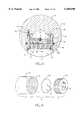
- FIG. 4is side view of the pressure pulsation sensor shown in FIG. 3.
- FIG. 5is a longitudinal cross-section taken along line V--V shown in FIG. 4.
- FIG. 6is a transverse cross-section taken along line VI--VI shown in FIG. 5.
- FIG. 7is a detailed view of the portion of the pressure pulsation sensor assembly shown in FIG. 6 enclosed by the circle denoted VII.
- FIG. 8is an exploded, isometric view of the piezoceramic sensor assembly shown in FIGS. 5 and 6.
- FIG. 9is a schematic electrical diagram of the pressure pulsation sensor shown in FIGS. 4-7.
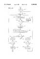
- FIG. 10is a flow chart showing the logic employed to determine if mud flow from the mud pumps has been established.
- FIG. 11is a flow chart showing the logic employed to determine if mud flow from the mud pumps has ceased.
- FIG. 12is a diagram, partially schematic, of a multilateral producing well incorporating remotely operated flow control devices according to the current invention that control the flow of fluid from the well branches.
- FIG. 13is a longitudinal cross-section, partially schematic, of one of the remotely operated flow control devices shown in FIG. 12.
- a drilling operation according to the current inventionis shown in FIG. 1.
- a drill rig 1drives a drill string 6 that, as is conventional, is comprised of a number of interconnected sections.
- a drill bit 3 at the extreme distal end of the drill string 6advances into an earthen formation 5 so as to form a bore 4.
- the drilling mud 28then flows through a central passage in the drill pipe 6 to a bottom hole assembly 10, which is formed at the distal end of the drill string 6. From the bottom hole assembly 10, the drilling mud 28 flows out through the drill bit 3 and returns to the surface through the annular passage 17 formed between the bore 4 and the drill string 6. At the surface, the drilling mud 28 is returned to the tank 13 via pipe 11.
- the bottom hole assembly 10is comprised of an MWD tool.
- the MWD toolcomprises a mud pulser 26, which, as previously discussed, uses techniques well known in the art to send pressure pulses from the bottom hole assembly 10 to the surface via the drilling mud 28.
- a strain gage based pressure transducer 9 at the surfacesenses the pressure pulses and transmits electrical signals to a data acquisition and analysis system 15 where the data encoded into the mud pulses is decoded and analyzed.
- the MWD toolincludes a solenoid driver 24 that drives the pulser valve, a control module 25 that contains a microprocessor 92, a directional sensor 22 that provides the directional information transmitted by the pulser 26, a battery module 20 that provides electrical power for the bottom hole assembly, a gamma sensor 18 that provides information concerning the natural radioactivity of the formation 5 that is transmitted by the pulser, a pressure pulsation sensor 16 according to the current invention, and a mud motor 14, which may be steerable.
- centralizer sectionsmay be mounted between the foregoing sections.
- many different configurations of bottom hole assemblies and MWD toolscan be used.
- other types of sensorssuch as nuclear detectors, resistivity sensors, etc., may be incorporated into the MWD tool.
- the pistons 11 of the mud pump 7generate pressure pulsations 21 in the drilling mud 28 being pumped down the drill string 6.
- Each piston 11generates pulsations at a frequency that is equal to the rate at which the piston strokes so that the pressure pulsations will have a frequency equal to the number of pistons multiplied by the stroke rate.
- mud pump pistons 11stroke at a rate in the range of about 30 to 150 strokes per minute.
- a simplex mud pumpwill generate pressure pulsations 21 at a frequency in the range of 0.5 to 2.5 Hz.
- a duplex pumpwhich employs two pistons, which are not in phase, will generate pressure pulsations 21 having a frequency in the range from 1.0 to 5.0 Hz
- a triplex pumpwhich employs three pistons, will generate pressure pulsations having a frequency in the range from 1.5 to 7.5 Hz.
- the pressure pulsations 21travel down the column of drilling mud within the passage 12 formed within drill string 6 and are eventually received as attenuated pressure pulsations 23 at the bottom hole assembly 10.
- the pressure pulsations 23are detected and analyzed by the pressure pulsation sensor 16, discussed in detail below.
- the pressure pulsation sensor electronicsdetermines whether the pressure pulsations indicate that the mud pump 7 is in operation. If the sensor 16 previously determined that the pressure pulsations 23 were indicative of mud pump operation and it continues to so determine, no action is taken. If, however, based on an analysis the pressure pulsations, or lack thereof, the sensor 16 determines that operation of the mud pumps has ceased, it signals the programmable microprocessor 92 that operation of the mud pump 7 has ceased. The microprocessor 92 will then respond to such a signal according to preprogramed instructions.
- the microprocessor 92responds to a signal indicating cessation of operation of the mud pump 7 by cutting off, or at least reducing, power to the sensors and other consumers of electrical power within the MWD tool. Electrical power is not restored until the pressure pulsation sensor 16 determines that operation of the mud pump 7 has resumed, as discussed below. Eliminating or reducing electrical power consumption whenever the mud pump 7 is not in operation, in which case drilling will have ceased, conserves the life of the battery module 20, thereby extending the time between outages of the drill rig required to replace the batteries in the battery module 20, and reduces the MWD operating costs.
- the pressure pulsation sensor 16continues to sense and analyze pressure pulsation proximate the bottom hole assembly 10 after it has been determined that the mud pump has stopped. If, based on this analysis, the sensor 16 determines that operation of the mud pumps has resumed, it signals the programmable microprocessor 92. The microprocessor 92 will then respond to such a signal according to another set of preprogramed instructions. For example, the microprocessor 92 may respond by restoring full power to the MWD tool, thereby allowing sensing and data transmission by the pulser 26 to resume. Preferably, the microprocessor 92 also responds to such a signal from the sensor 16 by re-initiating the data transmission sequence.
- thiscan include transmission of directional data and can permit the surface data acquisition system 15 to be synchronized with the data transmission from the bottom hole assembly 10.
- functionssuch as obtaining directional data and restoring data synchronization can be reliably accomplished by tripping and then restarting the mud pump 7.
- FIGS. 4-8A preferred embodiment of the pressure pulsation sensor 16 is shown in FIGS. 4-8.
- the sensor 16comprises a cylindrical, metallic housing 72 on which external threads 60 are formed at one end and internal threads 62 are formed at the other end, thereby allowing the sensor to be coupled and supported by adjacent modules of the bottom hole assembly or the MWD tool.
- a circular recess 32is formed in the side of the housing 72 so as to form a window through which drilling mud 28 may enter.
- a pressure sensor assembly 38shown best in FIGS. 6 and 8, is mounted within the recess 32.
- a snap ring 34inserted into a circular groove formed in the side wall 40 of the recess 32 maintains the sensor assembly 38 in place.
- An O-ring seal 68is incorporated within a second circular groove 66 formed in the recess side wall 68 and prevents drilling mud from entering the internal portion of the sensor 16.
- the sensor assembly 38is comprised of a diaphragm 44 formed by a circular face portion 45 and a rearwardly extending cylindrical skirt portion 48.
- the diaphragm 44must be sufficiently strong to withstand the pressure of the drilling mud 28, which can be as high as 25,000 psi. However, it should also have a relatively low modulus of elasticity so as to be sufficiently elastic to dynamically respond to the pressure pulsations, the magnitude of which may be as low as 1 psi by the time they reach the sensor 16.
- the diaphragm 38is formed from titanium. Threaded holes 36 are formed in the front surface of the diaphragm face 45 to facilitate removal of the sensor assembly 38.
- a piezoelectric element 50is mounted adjacent, and in surface contact with, the diaphragm 44. While piezoelectric elements can be made from a variety of materials, preferably, the piezoelectric element 50 is a piezoceramic element, which has a relatively high temperature capability (by contrast, piezoplastics, for example, cannot be used at temperatures in excess of 150° F.) and creates a relatively high voltage output when subjected to a minimum amount of strain. According to the piezoelectric phenomenon, certain crystalline substances, such as quartz and come ceramics, develop an electrical field when subjected to pressure.
- the piezoceramic element 50 according to the inventionis preferably formed by forming a dielectric material, such as lead Metaniebate or lead zirconate titanate, into the desired shape, in this case, a thin disk. Electrodes are then applied to the material. The dielectric material is heated to an elevated temperature in the presence of a strong DC electric field, which polarizes the ceramic so that the molecular dipoles are aligned in the direction of the applied field, thereby imparting dielectric properties to the element.
- a dielectric materialsuch as lead Metaniebate or lead zirconate titanate
- Piezoceramic elements 50have several attributes that make them especially suitable for down hole pressure pulsation sensing. They are compact. In one embodiment of a pressure pulsation sensor 16, the piezoceramic element 50 is approximately only 0.8 inch in diameter and 0.02 inch thick. Piezoelectric elements consume relatively little electric power compared to strain gage based pressure transducers. Also, unlike strain gage based pressure transducers, the piezoceramic element 50 is not affected by static pressure, which would otherwise create a DC offset, because the voltage change that occurs when a piezoceramic element is stressed is transient, returning to zero in a short time even if the stress is maintained. Suitable piezoceramic elements are available from Piezo Kinetics Incorporated, Pine Street and Mill Road, Bellefonte, Pa. 16823.
- the sensor assembly 38also includes a plug 46 mounted behind the piezoceramic element 50.
- the plug 38is preferably formed from an electrically insulating material, such as a thermoplastic. It has external threads formed on its outside surface that mate with internal threads formed on a skirt portion of the diaphragm 44.
- a dowel pin 54is disposed in mating holes 52 formed in the housing 72 and the diaphragm skirt 48 and prevents rotation of the sensor assembly 38.
- the piezoceramic element 50is maintained in intimate surface contact with the diaphragm 46 by compressing the edges of the element between the rear face of the diaphragm and the plug 46.
- the plug 46is threaded into the diaphragm skirt 48 so that it rests on the piezoelectric element 50, not the rear surface of the diaphragm face 45, thereby leaving a gap, indicated by G in FIG. 7, between the plug and the diaphragm face.
- the high pressure of the drilling mud 28causes static deflection of the diaphragm face 45, while pressure pulsations in the drilling mud 28 cause vibratory deflection of the diaphragm face.
- the compressive force supplied by the plug 46is sufficient to restrain the piezoceramic element 50 axially--that is, in the direction parallel to the axis of the diaphragm skirt 48--it does not prevent relative sliding motion of the piezoceramic element the radial direction--that is, in the plane of the element 50.
- the plug 46is threaded into the diaphragm skirt 48 so as to apply a 100 pound preloaded to the piezoelectric element 50.
- the conductor lead 56 from the piezoceramic element 50extends through a potted grommet 57 on an intermediate support plate 55 formed in the plug 46, and terminates at a printed circuit board 74.
- the intermediate support plate 55ensures that bending stresses are not imposed on the element from the conductor lead.
- the printed circuit board 74incorporates the sensor electronics, such as that required to receive and analyze the signal from the piezoceramic element 50, as discussed below.
- the printed circuit board 74is mounted on a chassis 70, using mounting screws (not shown) or potting, that is supported within the housing 72, thereby protecting the board from shock and vibration.
- the conductor 56feeds the output of the piezoceramic element 50 to the printed circuit board 74.
- Conductors 76extend from the printed circuit board 74 to a conventional pin connector 64, thereby allowing the output of the sensor 16 to be electrically connected to the microprocessor 92, discussed above.
- step 120the instantaneous voltage signal generated by the piezoceramic element 50, which as previously discussed is proportional to its deflection, is sampled by averaging its value over a predetermined period, preferably 1/30 of a second.
- the voltage signalwhich may be amplified, is preferably buffered by connecting an active filter 81, shown in FIG. 9, which preferably has approximately unity gain.
- Thisprovides a high impedance input, removes any high frequency components, and biases the signal within the range of the analog to digital converter 84, discussed below.
- thirty samples per secondare taken over a 1.6 second window, resulting in an array of 48 samples, although it will be readily appreciated that other sampling frequencies and sampling windows could also be utilized.
- the signalis then AC coupled to a sophisticated programmable sigma-delta analog to digital converter 84, shown in FIG. 9. Suitable analog to digital converters are available from Analog Devices, Inc. of Norwood, Mass.
- a high order programmable filteris incorporated into the analog to digital converter 84, thereby making it easy to reject all signals outside the frequency range of interest.
- the analog to digital converteris preferably programmed with a front-end gain of 8 and set up to acquire 16 bits of resolution. Thus, in steps 130 and 140, the sample count K is incremented with each sample collection until an array of 48 samples are obtained.
- the characteristic of the drilling mud pressure pulsations used to "code" the information contained in the pulsationsis preferably their frequency
- the digitized array of samplesis filtered using the programmable filter.
- the samplesare further filtered using a comb filter with a null at DC and the first frequency null at 10 Hz so as to remove any residual DC bias in the input data and allow the data processing to be performed at the maximum possible precision.
- filteringis preferably accomplished so as to remove the components of the pressure pulsation signal at frequencies below about 0.5 Hz, and to remove components above about 8 Hz, and preferably, above about 7.5 Hz.
- y(n)is the nth filtered sample.
- many other filtering functionscould also be utilized.
- the root mean square power P RMS of the filtered, digitized voltage signal from the piezoceramic element 50is computed.
- the root mean square power P RMS of the filtered signalis compared to a predetermined, but programmable, minimum threshold value. In some applications, this value should correspond to about a 1 psi variation in drilling mud pressure. However, since parameters such as the depth of the well and the type of drilling mud will affect the minimum threshold value, the value is programmable and can be adjusted based on field experience. If the power does not exceed the minimum threshold value (which would occur if the mud pump were not operating), the flow count F is decremented and compared to zero in steps 180 and 190. If the flow count is not less than zero, steps 110 to 170 are repeated--that is, another array of data is acquired and tested. If the flow count is less than zero, it is reset to zero in step 200 and steps 110 to 170 are then repeated.
- a predetermined, but programmable, minimum threshold valueIn some applications, this value should correspond to about a 1 psi variation in drilling mud pressure. However, since parameters such as the depth of the well and the type of drilling
- the flow count Fis incremented and then compared to a predetermined, but programmable, value (such as 10) in steps 210 and 220. If the flow count equals that value, the sensor 16 trips a logic switch in step 230 that signals the microprocessor 92 that the mud pumps are operating.
- the sensor 16determines that the mud pump is operating, and therefore that drilling mud is flowing and drilling is underway, if the instances of relatively high pressure pulsations in the appropriate frequency range--that is, instances in which the root mean square power of a filtered sample array of voltages from the piezoceramic element exceeds a predetermined minimum threshold value--occur with sufficient regularity. Sufficient regularity is found if, in comparison to the regularity of the instances in which the minimum threshold value is not exceeded, the regularity of the instances in which the minimum threshold value is exceeded causes a count that is incremented when the threshold value is exceeded, and decremented when it is not, to reach a predetermined minimum value, such as 10.
- the signal from the sensor 16 to the microprocessor 92 indicating the mud pump has begun operatingcan be used in a variety of ways. For example, it can trigger the restoration of electrical power to the MWD tool, the transmission a certain types of data, such as directional data, or the initialization of data transmission according to a predetermined format so as to allow the surface data acquisition system to be resynchronized.
- step 300a sample count H is set to a predetermined, but programmable, value, such as 15.
- a single sampleis then taken of the voltage from the piezoceramic element 50 in step 310. This signal is then filtered as described above in connection with the logic described in FIG. 10.
- step 330the amplitude of the filtered voltage signal is compared to a predetermined, but programmable, maximum threshold value, such as 0.5 psi, that is preferably different from the threshold value discussed in connection with FIG. 10 to provide some hysteresis. If the value is not less than the maximum threshold (which would occur whenever the mud pump were operating), the sample count H is reset and steps 310-330 are repeated. If the value is less than the maximum threshold (which would occur when the mud pump were not operating), the sample count is decremented and then compared to zero in steps 340 and 350. If the sample count is not yet equal to zero, steps 310-350 are repeated.
- a predetermined, but programmable, maximum threshold valuesuch as 0.5 psi, that is preferably different from the threshold value discussed in connection with FIG. 10 to provide some hysteresis.
- the flow count Fwhich was set to a predetermined value, such as 10, by the logic in FIG. 10, is decremented and then compared to zero in steps 360 and 370. If the flow count is not yet zero, steps 300 to 370 are repeated. If the flow count equals zero, the sensor 16 trips the logic switch in step 380 thereby signaling the microprocessor 92 that the mud pump has ceased operating.
- the senor 16determines that the mud pump has ceased operating, and therefore that drilling mud is not flowing and drilling is not underway, if the instances of a certain situation--i.e., those in which the filtered value of the voltage from the piezoceramic element is less than a predetermined maximum threshold value for a predetermined number of consecutive times, such as 15--occur a sufficient number of times, such as 10.
- a signal from the sensor 16 to the microprocessor 92 indicating that mud flow has ceased, after previously having determined that mud flow had been establishedcan be used, for example, to trigger a reduction, or complete cut-off, in the electrical power supplied to the MWD tool, or the initiation of the transmission of directional or other data, or the re-initializing of the data transmission sequence according to a predetermined format so that the surface acquisition system could be resynchronized.
- the sensor 16Once the sensor 16 has determined that operation of the mud pump has ceased, it begins checking to determine if operation has subsequently been reestablished using the logic shown in FIG. 10.
- the componentsinclude (i) the piezoceramic element 50 for generating a varying voltage signal in response to pressure pulsations, (ii) an active filter 81, (iii) an analog to digital converter 84 for digitizing the piezoceramic element signal, (iv) a programmable filter 82, which is incorporated into the analog to digital converter, for filtering out the portion of the signal from the piezoceramic element outside of a predetermined frequency range, (v) a sensor microprocessor 86 that, using techniques well known in the art, is programed with software for performing the logic operations previously discussed including incrementing and decrementing the counters and comparing the amplitude of the piezoceramic signal to predetermined threshold values, (vi) an EPROM 88 for storing programmable thresholds and data, (vii) a crystal oscillator 80, and (viii) a logic switch 90 for signal
- the current inventionhas been illustrated by reference to communicating information to the bottom hole assembly concerning whether the mud pump is operating, the invention could also be practiced by communicating other information from the surface to the bottom hole assembly, such as steering directions in a steerable drill string. Further, although the invention has been illustrated by analyzing the pressure pulsations attributable to the mud pump pistons, other sources of pressure pulsations, such as a pulser valve discussed below, could also be used to communicate with the bottom hole assembly.
- the current inventionis not limited to communicating information to a bottom hole assembly in a drill string but may also be used to communicate information to a device, such as a flow control device, in a producing well.
- a typical multilateral producing well 402is shown in FIG. 12.
- a number of branches, such as branches 402' and 402"extend from the main well bore at various locations.
- the fluid 406' and 406" from each of the branchescommingles in the well and flows up to the surface as a combined flow 406. For a variety of reasons, it is sometimes desirable to regulate, or entirely stop, the flow of fluid from one of the branches.
- such flow controlis readily remotely accomplished from the surface by incorporating a flow control device 407, shown in detail in FIG. 13, into each branch 402' and 402" of the well 402 and by installing a pressure pulsation generating device 411 in the fluid discharge piping 430 at the surface.
- the pressure pulsation generating device 411which is preferably a pulser valve similar to that currently found in MWD tools used in mud pulse telemetry systems, is controlled by a controller 410. Under the direction of the controller 410, the pulser 411 alternately restricts and unrestricts the flow of fluid 406 from the well 402, thereby generating pressure pulses 21' in the fluid.
- the pressure pulsationsare transmitted down the well 402 and are received as attenuated pressure pulsations 23' at the flow control devices 407 installed in each of the well branches 402' and 402".
- the pressure pulsationsare sensed by pressure pulsation sensors 416 mounted in the flow control device.
- the pressure pulsation sensors 416are similar to the pressure pulsation sensor 16 intended for use in the bottom hole assembly that is discussed above in connection with the embodiments shown FIGS. 1-11.
- FIG. 13One embodiment of a flow control device 407 for use in a multilateral well according to the current invention is shown in FIG. 13.
- fluid production tubing 412is disposed within the well bore 402" and directs the flow of well fluid 406" to the surface.
- a central passage 426is formed within the flow control device 407 that allows fluid 406" from the well to flow through the device.
- Isolation packers 414 at each end of the device 407mate with the production tubing 412 and prevent fluid 406" from flowing around the device.
- the device 407further includes a valve 422, a pressure pulsation sensor 416, and a turbine alternator 432.
- the valve 422may be a gate valve or any other conventional fluid flow isolation or control valve, and incorporates a motor driven operator 424.
- the turbine alternator 432is disposed within the central passage 426 and is driven by the well fluid 406".
- the pressure pulsation sensor 416is comprised of a cylindrical metal housing 417 in which a number of recesses are formed.
- Recess 32'which may be similar to recess 32 previously discussed in connection with FIGS. 4-8, houses the pressure sensor assembly 38 shown in FIGS. 6-8.
- the pressure assembly 38preferably contains a piezoceramic element that generates a voltage in response to pressure changes within the fluid 406".
- Two additional recesses 418are also formed in the housing 417, each of which is sealed by a hatch cover 419.
- the electronics package 74' for the flow control device 407which preferably includes a printed circuit board, is housed within one of the recesses 418, while a battery 421 is mounted within the other recess 418.
- the battery 421provides electrical power for the flow control device 407, including power for the valve 422 operator 424, and is trickle charged by the turbine alternator 432.
- a conductor 56'electrically connects the pressure sensor assembly 32 to the electronics package 74'.
- a second conductor 58electrically connects the electronics package 74' to the valve operator 424.
- the electronics package 74'preferably contains the electronic components and logic previously discussed in connection with FIGS. 9 and 10 that enable the pressure pulsation sensor 416 to reliably analyze a characteristic of the pressure pulsations, such as whether they contain pulsations within a predetermine frequency range, and thereby recognize whether a communication is being directed to it and, if so, what action should be taken. For example, if the pressure pulsation sensor 416 in flow control device 407" installed in branch 402" determines that the frequency of the pulsations 23' is in the 5 to 7 Hz range, it will direct a signal, via conductor 58, to the valve operator 424 causing it to close, or partially close, the valve 422.
- the sensor 416determines that the frequency is in the 8 to 10 Hz range, it will open, or partially open, the valve.
- the pressure sensor 416 in the flow control device 407' in the other well branch 402'is programed to ignore pulsations within the 5-10 Hz range. Instead, it will close its valve 422 if the frequency is in the 13 to 15 Hz range and open its valve if the frequency is in the 16 to 18 Hz range; frequencies that the sensor 416 in branch 407" are programed to ignore.
- the flow control device 407 of the current inventionallows well operating personnel to readily control the flow of fluid from the various branches in a multilateral producing well from the surface, and without a direct data link to the valves in the branches.
- the inventionhas been illustrated by using the frequency of the pressure pulsations to communicate information, other characteristics of the pressure pulsations, such as pulse pattern or duration, could also be used.
- the pressure pulsations 21'could contain information encoded in a binary format such as that currently employed in mud pulse telemetry systems, thereby allowing the communication of more complex directives rather than merely opening and closing and the control of devices other than valves. In that event, additional microprocessor capability and more sophisticated data acquisition system would be incorporated into the down hole device.
Landscapes
- Engineering & Computer Science (AREA)
- Physics & Mathematics (AREA)
- Life Sciences & Earth Sciences (AREA)
- Mining & Mineral Resources (AREA)
- Geology (AREA)
- Remote Sensing (AREA)
- Environmental & Geological Engineering (AREA)
- Fluid Mechanics (AREA)
- Geophysics (AREA)
- Acoustics & Sound (AREA)
- General Life Sciences & Earth Sciences (AREA)
- Geochemistry & Mineralogy (AREA)
- Measuring Fluid Pressure (AREA)
Abstract
Description
Claims (40)
Priority Applications (1)
| Application Number | Priority Date | Filing Date | Title |
|---|---|---|---|
| US09/086,418US6105690A (en) | 1998-05-29 | 1998-05-29 | Method and apparatus for communicating with devices downhole in a well especially adapted for use as a bottom hole mud flow sensor |
Applications Claiming Priority (1)
| Application Number | Priority Date | Filing Date | Title |
|---|---|---|---|
| US09/086,418US6105690A (en) | 1998-05-29 | 1998-05-29 | Method and apparatus for communicating with devices downhole in a well especially adapted for use as a bottom hole mud flow sensor |
Publications (1)
| Publication Number | Publication Date |
|---|---|
| US6105690Atrue US6105690A (en) | 2000-08-22 |
Family
ID=22198448
Family Applications (1)
| Application Number | Title | Priority Date | Filing Date |
|---|---|---|---|
| US09/086,418Expired - LifetimeUS6105690A (en) | 1998-05-29 | 1998-05-29 | Method and apparatus for communicating with devices downhole in a well especially adapted for use as a bottom hole mud flow sensor |
Country Status (1)
| Country | Link |
|---|---|
| US (1) | US6105690A (en) |
Cited By (83)
| Publication number | Priority date | Publication date | Assignee | Title |
|---|---|---|---|---|
| US6343649B1 (en)* | 1999-09-07 | 2002-02-05 | Halliburton Energy Services, Inc. | Methods and associated apparatus for downhole data retrieval, monitoring and tool actuation |
| WO2002065158A1 (en)* | 2001-02-14 | 2002-08-22 | Halliburton Energy Services, Inc. | Downlink telemetry system |
| US6443242B1 (en) | 2000-09-29 | 2002-09-03 | Ctes, L.C. | Method for wellbore operations using calculated wellbore parameters in real time |
| US6467557B1 (en) | 1998-12-18 | 2002-10-22 | Western Well Tool, Inc. | Long reach rotary drilling assembly |
| US6470974B1 (en)* | 1999-04-14 | 2002-10-29 | Western Well Tool, Inc. | Three-dimensional steering tool for controlled downhole extended-reach directional drilling |
| GB2375556A (en)* | 2001-01-22 | 2002-11-20 | Baker Hughes Inc | Operating a downhole well control tool using a downhole telemetry instrument |
| GB2377955A (en)* | 2001-07-25 | 2003-01-29 | Baker Hughes Inc | Detecting pressure signals generated by a downhole actuator |
| US20030029641A1 (en)* | 2001-07-25 | 2003-02-13 | Schlumberger Technology Corporation | Method and system for drilling a wellbore having cable based telemetry |
| US6526819B2 (en) | 2001-02-08 | 2003-03-04 | Weatherford/Lamb, Inc. | Method for analyzing a completion system |
| US20030056985A1 (en)* | 2001-02-27 | 2003-03-27 | Baker Hughes Incorporated | Oscillating shear valve for mud pulse telemetry |
| US20030076107A1 (en)* | 2001-08-03 | 2003-04-24 | Baker Hughes Incorporated | Method and apparatus for a multi-component induction instrument measuring system for geosteering and formation resistivity data interpretation in horizontal, vertical and deviated wells |
| US6597175B1 (en) | 1999-09-07 | 2003-07-22 | Halliburton Energy Services, Inc. | Electromagnetic detector apparatus and method for oil or gas well, and circuit-bearing displaceable object to be detected therein |
| US20030141055A1 (en)* | 1999-11-05 | 2003-07-31 | Paluch William C. | Drilling formation tester, apparatus and methods of testing and monitoring status of tester |
| US6616378B2 (en)* | 2000-03-02 | 2003-09-09 | Staploe Limited | Device and method for storing and protecting data relating to pipe installation |
| US20030200127A1 (en)* | 2002-04-18 | 2003-10-23 | Mcqueen Talmadge Keith | Job site problem solution systems with internet interface |
| US20030214287A1 (en)* | 2002-05-15 | 2003-11-20 | Boqin Sun | Methods of decoupling diffusion effects from relaxation times to determine properties of porous media containing fluids and multi-dimensional representation of those properties |
| US20030234120A1 (en)* | 1999-11-05 | 2003-12-25 | Paluch William C. | Drilling formation tester, apparatus and methods of testing and monitoring status of tester |
| US6677756B2 (en)* | 2001-08-03 | 2004-01-13 | Baker Hughes Incorporated | Multi-component induction instrument |
| US20040020709A1 (en)* | 2002-08-05 | 2004-02-05 | Paul Wilson | Slickline power control interface |
| GB2391880A (en)* | 2002-08-13 | 2004-02-18 | Reeves Wireline Tech Ltd | Apparatuses and methods for deploying logging tools and signalling in boreholes |
| US6714138B1 (en) | 2000-09-29 | 2004-03-30 | Aps Technology, Inc. | Method and apparatus for transmitting information to the surface from a drill string down hole in a well |
| US20040112645A1 (en)* | 2002-10-04 | 2004-06-17 | Halliburton Energy Services, Inc. | Method and apparatus for removing cuttings from a deviated wellbore |
| US20040195007A1 (en)* | 2003-04-02 | 2004-10-07 | Halliburton Energy Services, Inc. | Method and apparatus for increasing drilling capacity and removing cuttings when drilling with coiled tubing |
| US20040217879A1 (en)* | 2003-03-12 | 2004-11-04 | Varco International Inc. | Motor pulse controller |
| GB2403488A (en)* | 2003-07-04 | 2005-01-05 | Flight Refueling Ltd | Downhole data communication |
| US20050056465A1 (en)* | 2003-09-17 | 2005-03-17 | Virally Stephane J. | Automatic downlink system |
| US20050189142A1 (en)* | 2004-03-01 | 2005-09-01 | Schlumberger Technology Corporation | Wellbore drilling system and method |
| US20050254561A1 (en)* | 2004-05-12 | 2005-11-17 | Korea Electronics Technology Institute | Multi-standard transceiver for supporting wireless communications in 2.3-2.4 GHz band |
| US20050280419A1 (en)* | 2004-06-18 | 2005-12-22 | Schlumberger Technology Corporation | While-drilling apparatus for measuring streaming potentials and determining earth formation characteristics |
| US20050279495A1 (en)* | 2004-06-18 | 2005-12-22 | Schlumberger Technology Corporation, Incorporated In The State Of Texas | Methods for locating formation fractures and monitoring well completion using streaming potential transients information |
| US20060034154A1 (en)* | 2004-07-09 | 2006-02-16 | Perry Carl A | Rotary pulser for transmitting information to the surface from a drill string down hole in a well |
| US20060089804A1 (en)* | 2004-06-18 | 2006-04-27 | Schlumberger Technology Corporation | While-drilling methodology for determining earth formation characteristics and other useful information based upon streaming potential measurements |
| US20060125474A1 (en)* | 2004-06-18 | 2006-06-15 | Schlumberger Technology Corporation | While-drilling methodology for estimating formation pressure based upon streaming potential measurements |
| US20060219438A1 (en)* | 2005-04-05 | 2006-10-05 | Halliburton Energy Services, Inc. | Wireless communications in a drilling operations environment |
| US20060225920A1 (en)* | 2005-03-29 | 2006-10-12 | Baker Hughes Incorporated | Method and apparatus for downlink communication |
| US20060243487A1 (en)* | 2005-04-29 | 2006-11-02 | Aps Technology, Inc. | Rotary steerable motor system for underground drilling |
| US20060243489A1 (en)* | 2003-11-07 | 2006-11-02 | Wassell Mark E | System and method for damping vibration in a drill string |
| US20060260806A1 (en)* | 2005-05-23 | 2006-11-23 | Schlumberger Technology Corporation | Method and system for wellbore communication |
| US20070131453A1 (en)* | 2005-12-13 | 2007-06-14 | Yue Zhong Q | Automatic SPT monitor |
| US20070170924A1 (en)* | 2004-06-18 | 2007-07-26 | Schlumberger Technology Corporation | While-drilling apparatus for measuring streaming potentials and determining earth formation characteristics and other useful information |
| US7249968B1 (en) | 2004-08-16 | 2007-07-31 | Aps Technology, Inc. | Electrical connections for harsh conditions |
| US20070236221A1 (en)* | 2002-03-04 | 2007-10-11 | Baker Hughes Incorporated | Method and Apparatus for the Use of Multicomponent Induction Tool for Geosteering and Formation Resistivity Data Interpretation in Horizontal Wells |
| US20070256861A1 (en)* | 2006-05-05 | 2007-11-08 | Hulick Kent E | Bit face orientation control in drilling operations |
| US20070257679A1 (en)* | 2004-04-14 | 2007-11-08 | Baker Hughes Incorporated | Method and Apparatus for a Multi-component Induction Instrument Measuring System for Geosteering and Formation Resistivity Data Interpretation in Horizontal, Vertical and Deviated Wells |
| US20070256863A1 (en)* | 2006-05-05 | 2007-11-08 | Hulick Kent E | Directional drilling control |
| US20080007423A1 (en)* | 2005-03-29 | 2008-01-10 | Baker Hughes Incorporated | Method and Apparatus for Downlink Communication Using Dynamic Threshold Values for Detecting Transmitted Signals |
| GB2443096A (en)* | 2005-05-23 | 2008-04-23 | Schlumberger Holdings | Method and system for wellbore communication |
| US20080190605A1 (en)* | 2007-02-12 | 2008-08-14 | Timothy Dale Clapp | Apparatus and methods of flow testing formation zones |
| RU2351759C1 (en)* | 2007-09-07 | 2009-04-10 | Общество с ограниченной ответственностью Научно-производственная фирма "ВНИИГИС-Забойные телеметрические комплексы" (ООО НПФ "ВНИИГИС-ЗТК") | Device for measurings of geophysical and technological parameters in course of drilling with electromagnetic communication channel |
| US7520324B2 (en) | 2004-06-18 | 2009-04-21 | Schlumberger Technology Corporation | Completion apparatus for measuring streaming potentials and determining earth formation characteristics |
| US7586310B2 (en) | 2004-06-18 | 2009-09-08 | Schlumberger Technology Corporation | While-drilling apparatus for measuring streaming potentials and determining earth formation characteristics and other useful information |
| US20090242274A1 (en)* | 2004-06-18 | 2009-10-01 | Schlumberger Technology Corporation | Apparatus for measuring streaming potentials and determining earth formation characteristics |
| US20090261986A1 (en)* | 2008-04-17 | 2009-10-22 | Mehta Shyam B | Downlink while pumps are off |
| US20100110833A1 (en)* | 2006-07-26 | 2010-05-06 | Close David | Pressure release encoding system for communicating downhole information through a wellbore to a surface location |
| US20100224410A1 (en)* | 2009-03-05 | 2010-09-09 | Aps Technology Inc. | System and method for damping vibration in a drill string using a magnetorheological damper |
| US20100252325A1 (en)* | 2009-04-02 | 2010-10-07 | National Oilwell Varco | Methods for determining mechanical specific energy for wellbore operations |
| US20100300677A1 (en)* | 2007-09-27 | 2010-12-02 | Patterson Iii Albert E | Modular power source for subsurface systems |
| US20110169655A1 (en)* | 2010-01-11 | 2011-07-14 | Welltronics Applications, Llc | Method for a pressure release encoding system for communicating downhole information through a wellbore to a surface location |
| US20110168390A1 (en)* | 2008-09-24 | 2011-07-14 | Halliburton Energy Services, Inc. | Downhole electronics with pressure transfer medium |
| US20110286308A1 (en)* | 2010-05-24 | 2011-11-24 | Smith International, Inc. | Downlinking Communication System and Method |
| US8528219B2 (en) | 2009-08-17 | 2013-09-10 | Magnum Drilling Services, Inc. | Inclination measurement devices and methods of use |
| EP2647791A2 (en) | 2012-04-06 | 2013-10-09 | Gyrodata, Incorporated | Valve for communication of a measurement while drilling system |
| US8792304B2 (en) | 2010-05-24 | 2014-07-29 | Schlumberger Technology Corporation | Downlinking communication system and method using signal transition detection |
| US20140208847A1 (en)* | 2013-01-25 | 2014-07-31 | Esg Solutions Inc. | Sealed Sensor Assembly |
| US8881414B2 (en) | 2009-08-17 | 2014-11-11 | Magnum Drilling Services, Inc. | Inclination measurement devices and methods of use |
| US9238965B2 (en) | 2012-03-22 | 2016-01-19 | Aps Technology, Inc. | Rotary pulser and method for transmitting information to the surface from a drill string down hole in a well |
| US9458679B2 (en) | 2011-03-07 | 2016-10-04 | Aps Technology, Inc. | Apparatus and method for damping vibration in a drill string |
| US9500031B2 (en) | 2012-11-12 | 2016-11-22 | Aps Technology, Inc. | Rotary steerable drilling apparatus |
| US9540926B2 (en) | 2015-02-23 | 2017-01-10 | Aps Technology, Inc. | Mud-pulse telemetry system including a pulser for transmitting information along a drill string |
| US9714569B2 (en) | 2012-12-17 | 2017-07-25 | Evolution Engineering Inc. | Mud pulse telemetry apparatus with a pressure transducer and method of operating same |
| US9863191B1 (en) | 2014-05-02 | 2018-01-09 | Russell D. Ide | Flexible coupling |
| US9976360B2 (en) | 2009-03-05 | 2018-05-22 | Aps Technology, Inc. | System and method for damping vibration in a drill string using a magnetorheological damper |
| US10113363B2 (en) | 2014-11-07 | 2018-10-30 | Aps Technology, Inc. | System and related methods for control of a directional drilling operation |
| US10233700B2 (en) | 2015-03-31 | 2019-03-19 | Aps Technology, Inc. | Downhole drilling motor with an adjustment assembly |
| CN109751043A (en)* | 2017-11-01 | 2019-05-14 | 中国石油化工股份有限公司 | Pressure pulse coding/decoding system and method for strata pressure measurement while drilling tool |
| US10323511B2 (en) | 2017-02-15 | 2019-06-18 | Aps Technology, Inc. | Dual rotor pulser for transmitting information in a drilling system |
| US10337250B2 (en) | 2014-02-03 | 2019-07-02 | Aps Technology, Inc. | System, apparatus and method for guiding a drill bit based on forces applied to a drill bit, and drilling methods related to same |
| US10465506B2 (en) | 2016-11-07 | 2019-11-05 | Aps Technology, Inc. | Mud-pulse telemetry system including a pulser for transmitting information along a drill string |
| US10753201B2 (en) | 2012-12-17 | 2020-08-25 | Evolution Engineering Inc. | Mud pulse telemetry apparatus with a pressure transducer and method of operating same |
| US11162303B2 (en) | 2019-06-14 | 2021-11-02 | Aps Technology, Inc. | Rotary steerable tool with proportional control valve |
| CN114837659A (en)* | 2018-05-18 | 2022-08-02 | 中国石油化工股份有限公司 | Method for controlling measurement-while-drilling tools in a bottom hole assembly in a wellbore |
| US12000274B2 (en) | 2020-12-28 | 2024-06-04 | Halliburton Energy Services, Inc. | Wireless telemetry using a pressure switch and mechanical thresholding of the signal |
| US12247482B2 (en) | 2023-03-17 | 2025-03-11 | Halliburton Energy Services, Inc. | Wellbore downlink communication |
Citations (32)
| Publication number | Priority date | Publication date | Assignee | Title |
|---|---|---|---|---|
| US2901685A (en)* | 1954-10-18 | 1959-08-25 | Dresser Ind | Apparatus for earth borehole investigating and signaling |
| US2964116A (en)* | 1955-05-26 | 1960-12-13 | Dresser Ind | Signaling system |
| US2973505A (en)* | 1954-10-18 | 1961-02-28 | Dresser Ind | Method and apparatus for earth borehole investigating and signaling |
| US3065416A (en)* | 1960-03-21 | 1962-11-20 | Dresser Ind | Well apparatus |
| US3302457A (en)* | 1964-06-02 | 1967-02-07 | Sun Oil Co | Method and apparatus for telemetering in a bore hole by changing drilling mud pressure |
| US3309656A (en)* | 1964-06-10 | 1967-03-14 | Mobil Oil Corp | Logging-while-drilling system |
| US3693428A (en)* | 1970-07-24 | 1972-09-26 | Jean Pierre Le Peuvedic | Hydraulic control device for transmitting measuring values from the bottom of a well to the surface as pressure pulses through the drilling mud |
| US3727179A (en)* | 1969-08-08 | 1973-04-10 | Petrodata Inc | Data transmission responsive to synchronization signal |
| US3732728A (en)* | 1971-01-04 | 1973-05-15 | Fitzpatrick D | Bottom hole pressure and temperature indicator |
| US3736558A (en)* | 1970-07-30 | 1973-05-29 | Schlumberger Technology Corp | Data-signaling apparatus for well drilling tools |
| US3737843A (en)* | 1971-12-09 | 1973-06-05 | Aquitaine Petrole | Hydraulically controlled device for modulating the mud |
| US3739331A (en)* | 1971-07-06 | 1973-06-12 | Mobil Oil Corp | Logging-while-drilling apparatus |
| US3742443A (en)* | 1970-07-27 | 1973-06-26 | Mobil Oil Corp | Apparatus for improving signal-to-noise ratio in logging-while-drilling system |
| US3764968A (en)* | 1972-06-15 | 1973-10-09 | Schlumberger Technology Corp | Well bore data transmission apparatus with debris clearing apparatus |
| US3764970A (en)* | 1972-06-15 | 1973-10-09 | Schlumberger Technology Corp | Well bore data-transmission apparatus with debris clearing apparatus |
| US3770006A (en)* | 1972-08-02 | 1973-11-06 | Mobil Oil Corp | Logging-while-drilling tool |
| US3958217A (en)* | 1974-05-10 | 1976-05-18 | Teleco Inc. | Pilot operated mud-pulse valve |
| US3964556A (en)* | 1974-07-10 | 1976-06-22 | Gearhart-Owen Industries, Inc. | Downhole signaling system |
| US4038632A (en)* | 1972-10-02 | 1977-07-26 | Del Norte Technology, Inc. | Oil and gas well disaster valve control system |
| US4351037A (en)* | 1977-12-05 | 1982-09-21 | Scherbatskoy Serge Alexander | Systems, apparatus and methods for measuring while drilling |
| US4483394A (en)* | 1982-11-01 | 1984-11-20 | Dresser Industries, Inc. | Hydraulic power unit for measurement while drilling apparatus |
| US4499955A (en)* | 1983-08-12 | 1985-02-19 | Chevron Research Company | Battery powered means and method for facilitating measurements while coring |
| US4553598A (en)* | 1981-08-06 | 1985-11-19 | Schlumberger Technology Corporation | Full bore sampler valve apparatus |
| US4628495A (en)* | 1982-08-09 | 1986-12-09 | Dresser Industries, Inc. | Measuring while drilling apparatus mud pressure signal valve |
| US4790393A (en)* | 1983-01-24 | 1988-12-13 | Nl Industries, Inc. | Valve for drilling fluid telemetry systems |
| US4796699A (en)* | 1988-05-26 | 1989-01-10 | Schlumberger Technology Corporation | Well tool control system and method |
| US4856595A (en)* | 1988-05-26 | 1989-08-15 | Schlumberger Technology Corporation | Well tool control system and method |
| US5079750A (en)* | 1977-12-05 | 1992-01-07 | Scherbatskoy Serge Alexander | Method and apparatus for transmitting information in a borehole employing discrimination |
| US5113379A (en)* | 1977-12-05 | 1992-05-12 | Scherbatskoy Serge Alexander | Method and apparatus for communicating between spaced locations in a borehole |
| US5144245A (en)* | 1991-04-05 | 1992-09-01 | Teleco Oilfield Services Inc. | Method for evaluating a borehole formation based on a formation resistivity log generated by a wave propagation formation evaluation tool |
| US5280243A (en)* | 1990-12-05 | 1994-01-18 | Numar Corporation | System for logging a well during the drilling thereof |
| US5691712A (en)* | 1995-07-25 | 1997-11-25 | Schlumberger Technology Corporation | Multiple wellbore tool apparatus including a plurality of microprocessor implemented wellbore tools for operating a corresponding plurality of included wellbore tools and acoustic transducers in response to stimulus signals and acoustic signals |
- 1998
- 1998-05-29USUS09/086,418patent/US6105690A/ennot_activeExpired - Lifetime
Patent Citations (34)
| Publication number | Priority date | Publication date | Assignee | Title |
|---|---|---|---|---|
| US2901685A (en)* | 1954-10-18 | 1959-08-25 | Dresser Ind | Apparatus for earth borehole investigating and signaling |
| US2973505A (en)* | 1954-10-18 | 1961-02-28 | Dresser Ind | Method and apparatus for earth borehole investigating and signaling |
| US2964116A (en)* | 1955-05-26 | 1960-12-13 | Dresser Ind | Signaling system |
| US3065416A (en)* | 1960-03-21 | 1962-11-20 | Dresser Ind | Well apparatus |
| US3302457A (en)* | 1964-06-02 | 1967-02-07 | Sun Oil Co | Method and apparatus for telemetering in a bore hole by changing drilling mud pressure |
| US3309656A (en)* | 1964-06-10 | 1967-03-14 | Mobil Oil Corp | Logging-while-drilling system |
| US3727179A (en)* | 1969-08-08 | 1973-04-10 | Petrodata Inc | Data transmission responsive to synchronization signal |
| US3693428A (en)* | 1970-07-24 | 1972-09-26 | Jean Pierre Le Peuvedic | Hydraulic control device for transmitting measuring values from the bottom of a well to the surface as pressure pulses through the drilling mud |
| US3742443A (en)* | 1970-07-27 | 1973-06-26 | Mobil Oil Corp | Apparatus for improving signal-to-noise ratio in logging-while-drilling system |
| US3736558A (en)* | 1970-07-30 | 1973-05-29 | Schlumberger Technology Corp | Data-signaling apparatus for well drilling tools |
| US3732728A (en)* | 1971-01-04 | 1973-05-15 | Fitzpatrick D | Bottom hole pressure and temperature indicator |
| US3739331A (en)* | 1971-07-06 | 1973-06-12 | Mobil Oil Corp | Logging-while-drilling apparatus |
| US3737843A (en)* | 1971-12-09 | 1973-06-05 | Aquitaine Petrole | Hydraulically controlled device for modulating the mud |
| US3764968A (en)* | 1972-06-15 | 1973-10-09 | Schlumberger Technology Corp | Well bore data transmission apparatus with debris clearing apparatus |
| US3764970A (en)* | 1972-06-15 | 1973-10-09 | Schlumberger Technology Corp | Well bore data-transmission apparatus with debris clearing apparatus |
| US3770006A (en)* | 1972-08-02 | 1973-11-06 | Mobil Oil Corp | Logging-while-drilling tool |
| US4038632A (en)* | 1972-10-02 | 1977-07-26 | Del Norte Technology, Inc. | Oil and gas well disaster valve control system |
| US3958217A (en)* | 1974-05-10 | 1976-05-18 | Teleco Inc. | Pilot operated mud-pulse valve |
| US3964556A (en)* | 1974-07-10 | 1976-06-22 | Gearhart-Owen Industries, Inc. | Downhole signaling system |
| US5079750A (en)* | 1977-12-05 | 1992-01-07 | Scherbatskoy Serge Alexander | Method and apparatus for transmitting information in a borehole employing discrimination |
| US4351037A (en)* | 1977-12-05 | 1982-09-21 | Scherbatskoy Serge Alexander | Systems, apparatus and methods for measuring while drilling |
| US5113379A (en)* | 1977-12-05 | 1992-05-12 | Scherbatskoy Serge Alexander | Method and apparatus for communicating between spaced locations in a borehole |
| US4553598A (en)* | 1981-08-06 | 1985-11-19 | Schlumberger Technology Corporation | Full bore sampler valve apparatus |
| US4628495A (en)* | 1982-08-09 | 1986-12-09 | Dresser Industries, Inc. | Measuring while drilling apparatus mud pressure signal valve |
| US4483394A (en)* | 1982-11-01 | 1984-11-20 | Dresser Industries, Inc. | Hydraulic power unit for measurement while drilling apparatus |
| US4790393A (en)* | 1983-01-24 | 1988-12-13 | Nl Industries, Inc. | Valve for drilling fluid telemetry systems |
| US4499955A (en)* | 1983-08-12 | 1985-02-19 | Chevron Research Company | Battery powered means and method for facilitating measurements while coring |
| US4856595A (en)* | 1988-05-26 | 1989-08-15 | Schlumberger Technology Corporation | Well tool control system and method |
| US4915168A (en)* | 1988-05-26 | 1990-04-10 | Schlumberger Technology Corporation | Multiple well tool control systems in a multi-valve well testing system |
| US4796699A (en)* | 1988-05-26 | 1989-01-10 | Schlumberger Technology Corporation | Well tool control system and method |
| US4915168B1 (en)* | 1988-05-26 | 1994-09-13 | Schlumberger Technology Corp | Multiple well tool control systems in a multi-valve well testing system |
| US5280243A (en)* | 1990-12-05 | 1994-01-18 | Numar Corporation | System for logging a well during the drilling thereof |
| US5144245A (en)* | 1991-04-05 | 1992-09-01 | Teleco Oilfield Services Inc. | Method for evaluating a borehole formation based on a formation resistivity log generated by a wave propagation formation evaluation tool |
| US5691712A (en)* | 1995-07-25 | 1997-11-25 | Schlumberger Technology Corporation | Multiple wellbore tool apparatus including a plurality of microprocessor implemented wellbore tools for operating a corresponding plurality of included wellbore tools and acoustic transducers in response to stimulus signals and acoustic signals |
Non-Patent Citations (4)
| Title |
|---|
| Piezo Kinetics Incorporated, "The Piezoelectric Effect", Piezoceramics--Application Notes, pp. 1-8 (1994). |
| Piezo Kinetics Incorporated, The Piezoelectric Effect , Piezoceramics Application Notes, pp. 1 8 (1994).* |
| Ryan Energy Technologies, Inc., "Electronic Flow Switch (EFS)", New Technology Bulletin, Offshore Technology Conference, Houston, TX, May 7, 1998, 1 page. |
| Ryan Energy Technologies, Inc., Electronic Flow Switch (EFS) , New Technology Bulletin, Offshore Technology Conference, Houston, TX, May 7, 1998, 1 page.* |
Cited By (197)
| Publication number | Priority date | Publication date | Assignee | Title |
|---|---|---|---|---|
| US6467557B1 (en) | 1998-12-18 | 2002-10-22 | Western Well Tool, Inc. | Long reach rotary drilling assembly |
| US6942044B2 (en) | 1999-04-14 | 2005-09-13 | Western Well Tools, Inc. | Three-dimensional steering tool for controlled downhole extended-reach directional drilling |
| US6708783B2 (en) | 1999-04-14 | 2004-03-23 | Western Well Tool, Inc. | Three-dimensional steering tool for controlled downhole extended-reach directional drilling |
| US20040084219A1 (en)* | 1999-04-14 | 2004-05-06 | Western Well Tool, Inc. | Three-dimensional steering tool for controlled downhole extended-reach directional drilling |
| US20040173381A1 (en)* | 1999-04-14 | 2004-09-09 | Moore N. Bruce | Three-dimensional steering tool for controlled downhole extended-reach directional drilling |
| US6470974B1 (en)* | 1999-04-14 | 2002-10-29 | Western Well Tool, Inc. | Three-dimensional steering tool for controlled downhole extended-reach directional drilling |
| US6588505B2 (en) | 1999-09-07 | 2003-07-08 | Halliburton Energy Services, Inc. | Methods and associated apparatus for downhole data retrieval, monitoring and tool actuation |
| US6497280B2 (en) | 1999-09-07 | 2002-12-24 | Halliburton Energy Services, Inc. | Methods and associated apparatus for downhole data retrieval, monitoring and tool actuation |
| US6481505B2 (en) | 1999-09-07 | 2002-11-19 | Halliburton Energy Services, Inc. | Methods and associated apparatus for downhole data retrieval, monitoring and tool actuation |
| US6359569B2 (en) | 1999-09-07 | 2002-03-19 | Halliburton Energy Services, Inc. | Methods and associated apparatus for downhole data retrieval, monitoring and tool actuation |
| US6343649B1 (en)* | 1999-09-07 | 2002-02-05 | Halliburton Energy Services, Inc. | Methods and associated apparatus for downhole data retrieval, monitoring and tool actuation |
| US6597175B1 (en) | 1999-09-07 | 2003-07-22 | Halliburton Energy Services, Inc. | Electromagnetic detector apparatus and method for oil or gas well, and circuit-bearing displaceable object to be detected therein |
| US20030234120A1 (en)* | 1999-11-05 | 2003-12-25 | Paluch William C. | Drilling formation tester, apparatus and methods of testing and monitoring status of tester |
| US7093674B2 (en)* | 1999-11-05 | 2006-08-22 | Halliburton Energy Services, Inc. | Drilling formation tester, apparatus and methods of testing and monitoring status of tester |
| US20030141055A1 (en)* | 1999-11-05 | 2003-07-31 | Paluch William C. | Drilling formation tester, apparatus and methods of testing and monitoring status of tester |
| US6616378B2 (en)* | 2000-03-02 | 2003-09-09 | Staploe Limited | Device and method for storing and protecting data relating to pipe installation |
| US6714138B1 (en) | 2000-09-29 | 2004-03-30 | Aps Technology, Inc. | Method and apparatus for transmitting information to the surface from a drill string down hole in a well |
| US6443242B1 (en) | 2000-09-29 | 2002-09-03 | Ctes, L.C. | Method for wellbore operations using calculated wellbore parameters in real time |
| AU785413B2 (en)* | 2001-01-22 | 2007-05-03 | Baker Hughes Incorporated | Wireless packer/anchor setting or activation |
| US6684953B2 (en) | 2001-01-22 | 2004-02-03 | Baker Hughes Incorporated | Wireless packer/anchor setting or activation |
| GB2375556A (en)* | 2001-01-22 | 2002-11-20 | Baker Hughes Inc | Operating a downhole well control tool using a downhole telemetry instrument |
| GB2375556B (en)* | 2001-01-22 | 2005-07-06 | Baker Hughes Inc | Method and apparatus for setting or activation of downhole devices |
| US6526819B2 (en) | 2001-02-08 | 2003-03-04 | Weatherford/Lamb, Inc. | Method for analyzing a completion system |
| GB2390864B (en)* | 2001-02-14 | 2005-05-11 | Halliburton Energy Serv Inc | Downlink telemetry system |
| NO342178B1 (en)* | 2001-02-14 | 2018-04-09 | Halliburton Energy Services Inc | Steps to Increase or Decrease Data Speed by Downlink Signaling to a Downhole Device |
| GB2390864A (en)* | 2001-02-14 | 2004-01-21 | Halliburton Energy Serv Inc | Downlink telemetry system |
| GB2413578B (en)* | 2001-02-14 | 2006-06-28 | Halliburton Energy Serv Inc | Downlink telemetry system |
| WO2002065158A1 (en)* | 2001-02-14 | 2002-08-22 | Halliburton Energy Services, Inc. | Downlink telemetry system |
| US6920085B2 (en) | 2001-02-14 | 2005-07-19 | Halliburton Energy Services, Inc. | Downlink telemetry system |
| GB2413578A (en)* | 2001-02-14 | 2005-11-02 | Halliburton Energy Serv Inc | Communicating with a subsurface assembly |
| US7280432B2 (en) | 2001-02-27 | 2007-10-09 | Baker Hughes Incorporated | Oscillating shear valve for mud pulse telemetry |
| US6975244B2 (en) | 2001-02-27 | 2005-12-13 | Baker Hughes Incorporated | Oscillating shear valve for mud pulse telemetry and associated methods of use |
| US20030056985A1 (en)* | 2001-02-27 | 2003-03-27 | Baker Hughes Incorporated | Oscillating shear valve for mud pulse telemetry |
| US20060118334A1 (en)* | 2001-02-27 | 2006-06-08 | Baker Hughes Incorporated | Oscillating shear valve for mud pulse telemetry |
| GB2377955B (en)* | 2001-07-25 | 2003-10-01 | Baker Hughes Inc | A system and methods for detecting pressure signals generated by a downhole actator |
| GB2377955A (en)* | 2001-07-25 | 2003-01-29 | Baker Hughes Inc | Detecting pressure signals generated by a downhole actuator |
| US6776233B2 (en)* | 2001-07-25 | 2004-08-17 | Schlumberger Technology Corporation | Method and system for drilling a wellbore having cable based telemetry |
| US20030026167A1 (en)* | 2001-07-25 | 2003-02-06 | Baker Hughes Incorporated | System and methods for detecting pressure signals generated by a downhole actuator |
| US20030029641A1 (en)* | 2001-07-25 | 2003-02-13 | Schlumberger Technology Corporation | Method and system for drilling a wellbore having cable based telemetry |
| US7268556B2 (en) | 2001-08-03 | 2007-09-11 | Baker Hughes Incorporated | Method and apparatus for a multi-component induction instrument measuring system for geosteering and formation resistivity data interpretation in horizontal, vertical and deviated wells |
| US6677756B2 (en)* | 2001-08-03 | 2004-01-13 | Baker Hughes Incorporated | Multi-component induction instrument |
| US20030076107A1 (en)* | 2001-08-03 | 2003-04-24 | Baker Hughes Incorporated | Method and apparatus for a multi-component induction instrument measuring system for geosteering and formation resistivity data interpretation in horizontal, vertical and deviated wells |
| US6900640B2 (en)* | 2001-08-03 | 2005-05-31 | Baker Hughes Incorporated | Method and apparatus for a multi-component induction instrument measuring system for geosteering and formation resistivity data interpretation in horizontal, vertical and deviated wells |
| US20070236221A1 (en)* | 2002-03-04 | 2007-10-11 | Baker Hughes Incorporated | Method and Apparatus for the Use of Multicomponent Induction Tool for Geosteering and Formation Resistivity Data Interpretation in Horizontal Wells |
| US7612566B2 (en) | 2002-03-04 | 2009-11-03 | Baker Hughes Incorporated | Method and apparatus for the use of multicomponent induction tool for geosteering and formation resistivity data interpretation in horizontal wells |
| US20030200127A1 (en)* | 2002-04-18 | 2003-10-23 | Mcqueen Talmadge Keith | Job site problem solution systems with internet interface |
| US20030214287A1 (en)* | 2002-05-15 | 2003-11-20 | Boqin Sun | Methods of decoupling diffusion effects from relaxation times to determine properties of porous media containing fluids and multi-dimensional representation of those properties |
| US6833698B2 (en)* | 2002-05-15 | 2004-12-21 | Chevrontexaco U.S.A. Inc. | Methods of decoupling diffusion effects from relaxation times to determine properties of porous media containing fluids |
| US6945330B2 (en)* | 2002-08-05 | 2005-09-20 | Weatherford/Lamb, Inc. | Slickline power control interface |
| US7152680B2 (en) | 2002-08-05 | 2006-12-26 | Weatherford/Lamb, Inc. | Slickline power control interface |
| US20050279503A1 (en)* | 2002-08-05 | 2005-12-22 | Weatherford/Lamb, Inc. | Slickline power control interface |
| US20040020709A1 (en)* | 2002-08-05 | 2004-02-05 | Paul Wilson | Slickline power control interface |
| GB2391880B (en)* | 2002-08-13 | 2006-02-22 | Reeves Wireline Tech Ltd | Apparatuses and methods for deploying logging tools and signalling in boreholes |
| US20040069488A1 (en)* | 2002-08-13 | 2004-04-15 | Chaplin Michael John | Apparatuses and methods for deploying logging tools and signalling in boreholes |
| US7201231B2 (en) | 2002-08-13 | 2007-04-10 | Reeves Wireline Technologies Limited | Apparatuses and methods for deploying logging tools and signalling in boreholes |
| GB2391880A (en)* | 2002-08-13 | 2004-02-18 | Reeves Wireline Tech Ltd | Apparatuses and methods for deploying logging tools and signalling in boreholes |
| US20040112645A1 (en)* | 2002-10-04 | 2004-06-17 | Halliburton Energy Services, Inc. | Method and apparatus for removing cuttings from a deviated wellbore |
| US7114582B2 (en) | 2002-10-04 | 2006-10-03 | Halliburton Energy Services, Inc. | Method and apparatus for removing cuttings from a deviated wellbore |
| GB2416554A (en)* | 2003-03-12 | 2006-02-01 | Varco Int | A motor pulse controller |
| WO2004081335A3 (en)* | 2003-03-12 | 2005-04-28 | Varco Int | A motor pulse controller |
| US7026950B2 (en) | 2003-03-12 | 2006-04-11 | Varco I/P, Inc. | Motor pulse controller |
| GB2416554B (en)* | 2003-03-12 | 2006-12-27 | Varco Int | A motor pulse controller |
| NO337487B1 (en)* | 2003-03-12 | 2016-04-25 | Varco I/P Inc | Method and apparatus for transmitting commands to a downhole device. |
| US20040217879A1 (en)* | 2003-03-12 | 2004-11-04 | Varco International Inc. | Motor pulse controller |
| US6997272B2 (en) | 2003-04-02 | 2006-02-14 | Halliburton Energy Services, Inc. | Method and apparatus for increasing drilling capacity and removing cuttings when drilling with coiled tubing |
| US20040195007A1 (en)* | 2003-04-02 | 2004-10-07 | Halliburton Energy Services, Inc. | Method and apparatus for increasing drilling capacity and removing cuttings when drilling with coiled tubing |
| US7460438B2 (en) | 2003-07-04 | 2008-12-02 | Expro North Sea Limited | Downhole data communication |
| US20060164256A1 (en)* | 2003-07-04 | 2006-07-27 | Hudson Steven M | Downhole data communication |
| GB2403488A (en)* | 2003-07-04 | 2005-01-05 | Flight Refueling Ltd | Downhole data communication |
| WO2005005778A1 (en)* | 2003-07-04 | 2005-01-20 | Expro North Sea Limited | Downhole Data Communication |
| GB2403488B (en)* | 2003-07-04 | 2005-10-05 | Flight Refueling Ltd | Downhole data communication |
| EP2374993A1 (en)* | 2003-07-04 | 2011-10-12 | Expro North Sea Limited | Downhole data communication |
| NO344667B1 (en)* | 2003-07-04 | 2020-03-02 | Expro North Sea Ltd | Data communication downhole |
| GB2444434A (en)* | 2003-09-17 | 2008-06-04 | Schlumberger Holdings | Selective control of multi-piston mud pump to create downlink pulse |
| US7380616B2 (en) | 2003-09-17 | 2008-06-03 | Schlumberger Technology Corporation | Automatic downlink system |
| US20060102340A1 (en)* | 2003-09-17 | 2006-05-18 | Virally Stephane J | Automatic downlink system |
| US7320370B2 (en) | 2003-09-17 | 2008-01-22 | Schlumberger Technology Corporation | Automatic downlink system |
| US7198102B2 (en) | 2003-09-17 | 2007-04-03 | Schlumberger Technology Corporation | Automatic downlink system |
| GB2444657B (en)* | 2003-09-17 | 2008-07-23 | Schlumberger Holdings | Automatic downlink system |
| GB2406111A (en)* | 2003-09-17 | 2005-03-23 | Schlumberger Holdings | Downlink system using mud pulse telemetry |
| US20050056465A1 (en)* | 2003-09-17 | 2005-03-17 | Virally Stephane J. | Automatic downlink system |
| GB2406111B (en)* | 2003-09-17 | 2007-05-30 | Schlumberger Holdings | Automatic downlink system |
| GB2444657A (en)* | 2003-09-17 | 2008-06-11 | Schlumberger Holdings | Downlink pump connected to standpipe for generating mud pulses |
| GB2444434B (en)* | 2003-09-17 | 2008-07-16 | Schlumberger Holdings | Automatic downlink system |
| US8944190B2 (en) | 2003-11-07 | 2015-02-03 | Aps Technology, Inc. | System and method for damping vibration in a drill string |
| US8662205B2 (en) | 2003-11-07 | 2014-03-04 | Aps Technology, Inc. | System and method for damping vibration in a drill string |
| US20070284148A1 (en)* | 2003-11-07 | 2007-12-13 | Aps Technology, Inc. | System and method for damping vibration in a drill string |
| US7219752B2 (en) | 2003-11-07 | 2007-05-22 | Aps Technologies, Inc. | System and method for damping vibration in a drill string |
| US7377339B2 (en) | 2003-11-07 | 2008-05-27 | Aps Technology, Inc. | System and method for damping vibration in a drill string |
| US20060243489A1 (en)* | 2003-11-07 | 2006-11-02 | Wassell Mark E | System and method for damping vibration in a drill string |
| US8240401B2 (en) | 2003-11-07 | 2012-08-14 | Aps Technology, Inc. | System and method for damping vibration in a drill string |
| US7997357B2 (en) | 2003-11-07 | 2011-08-16 | Aps Technology, Inc. | System and method for damping vibration in a drill string |
| US7832500B2 (en) | 2004-03-01 | 2010-11-16 | Schlumberger Technology Corporation | Wellbore drilling method |
| US20050189142A1 (en)* | 2004-03-01 | 2005-09-01 | Schlumberger Technology Corporation | Wellbore drilling system and method |
| US20070257679A1 (en)* | 2004-04-14 | 2007-11-08 | Baker Hughes Incorporated | Method and Apparatus for a Multi-component Induction Instrument Measuring System for Geosteering and Formation Resistivity Data Interpretation in Horizontal, Vertical and Deviated Wells |
| US7719282B2 (en) | 2004-04-14 | 2010-05-18 | Baker Hughes Incorporated | Method and apparatus for mulit-component induction instrument measuring system for geosteering and formation resistivity data interpretation in horizontal, vertical and deviated wells |
| US20050254561A1 (en)* | 2004-05-12 | 2005-11-17 | Korea Electronics Technology Institute | Multi-standard transceiver for supporting wireless communications in 2.3-2.4 GHz band |
| US7526018B2 (en)* | 2004-05-12 | 2009-04-28 | Korea Electronics Technology Institute | Multi-standard transceiver for supporting wireless communications in 2.3-2.4 GHz band |
| US7891417B2 (en)* | 2004-06-18 | 2011-02-22 | Schlumberger Technology Corporation | Completion apparatus for measuring streaming potentials and determining earth formation characteristics |
| US20060125474A1 (en)* | 2004-06-18 | 2006-06-15 | Schlumberger Technology Corporation | While-drilling methodology for estimating formation pressure based upon streaming potential measurements |
| US8302687B2 (en) | 2004-06-18 | 2012-11-06 | Schlumberger Technology Corporation | Apparatus for measuring streaming potentials and determining earth formation characteristics |
| US7520324B2 (en) | 2004-06-18 | 2009-04-21 | Schlumberger Technology Corporation | Completion apparatus for measuring streaming potentials and determining earth formation characteristics |
| US20070170924A1 (en)* | 2004-06-18 | 2007-07-26 | Schlumberger Technology Corporation | While-drilling apparatus for measuring streaming potentials and determining earth formation characteristics and other useful information |
| US7388380B2 (en) | 2004-06-18 | 2008-06-17 | Schlumberger Technology | While-drilling apparatus for measuring streaming potentials and determining earth formation characteristics and other useful information |
| US7243718B2 (en) | 2004-06-18 | 2007-07-17 | Schlumberger Technology Corporation | Methods for locating formation fractures and monitoring well completion using streaming potential transients information |
| US7233150B2 (en)* | 2004-06-18 | 2007-06-19 | Schlumberger Technology Corporation | While-drilling apparatus for measuring streaming potentials and determining earth formation characteristics |
| US7466136B2 (en) | 2004-06-18 | 2008-12-16 | Schlumberger Technology Corporation | While-drilling methodology for determining earth formation characteristics and other useful information based upon streaming potential measurements |
| US7301345B2 (en) | 2004-06-18 | 2007-11-27 | Schlumberger Technology Corporation | While-drilling methodology for estimating formation pressure based upon streaming potential measurements |
| US20050280419A1 (en)* | 2004-06-18 | 2005-12-22 | Schlumberger Technology Corporation | While-drilling apparatus for measuring streaming potentials and determining earth formation characteristics |
| US20090242274A1 (en)* | 2004-06-18 | 2009-10-01 | Schlumberger Technology Corporation | Apparatus for measuring streaming potentials and determining earth formation characteristics |
| US7586310B2 (en) | 2004-06-18 | 2009-09-08 | Schlumberger Technology Corporation | While-drilling apparatus for measuring streaming potentials and determining earth formation characteristics and other useful information |
| US20090166024A1 (en)* | 2004-06-18 | 2009-07-02 | Schlumberger Technology Corporation | Completion apparatus for measuring streaming potentials and determining earth formation characteristics |
| US20060089804A1 (en)* | 2004-06-18 | 2006-04-27 | Schlumberger Technology Corporation | While-drilling methodology for determining earth formation characteristics and other useful information based upon streaming potential measurements |
| US20050279495A1 (en)* | 2004-06-18 | 2005-12-22 | Schlumberger Technology Corporation, Incorporated In The State Of Texas | Methods for locating formation fractures and monitoring well completion using streaming potential transients information |
| US9644477B2 (en) | 2004-07-01 | 2017-05-09 | Halliburton Energy Services, Inc. | Wireless communications in a drilling operations environment |
| US7327634B2 (en) | 2004-07-09 | 2008-02-05 | Aps Technology, Inc. | Rotary pulser for transmitting information to the surface from a drill string down hole in a well |
| US20060034154A1 (en)* | 2004-07-09 | 2006-02-16 | Perry Carl A | Rotary pulser for transmitting information to the surface from a drill string down hole in a well |
| US7249968B1 (en) | 2004-08-16 | 2007-07-31 | Aps Technology, Inc. | Electrical connections for harsh conditions |
| US7518950B2 (en) | 2005-03-29 | 2009-04-14 | Baker Hughes Incorporated | Method and apparatus for downlink communication |
| US20080007423A1 (en)* | 2005-03-29 | 2008-01-10 | Baker Hughes Incorporated | Method and Apparatus for Downlink Communication Using Dynamic Threshold Values for Detecting Transmitted Signals |
| US7983113B2 (en) | 2005-03-29 | 2011-07-19 | Baker Hughes Incorporated | Method and apparatus for downlink communication using dynamic threshold values for detecting transmitted signals |
| US20060225920A1 (en)* | 2005-03-29 | 2006-10-12 | Baker Hughes Incorporated | Method and apparatus for downlink communication |
| US20060219438A1 (en)* | 2005-04-05 | 2006-10-05 | Halliburton Energy Services, Inc. | Wireless communications in a drilling operations environment |
| US8544564B2 (en) | 2005-04-05 | 2013-10-01 | Halliburton Energy Services, Inc. | Wireless communications in a drilling operations environment |
| US7762356B2 (en) | 2005-04-29 | 2010-07-27 | Aps Technology, Inc. | Rotary steerable motor system for underground drilling |
| US7389830B2 (en) | 2005-04-29 | 2008-06-24 | Aps Technology, Inc. | Rotary steerable motor system for underground drilling |
| US20090008151A1 (en)* | 2005-04-29 | 2009-01-08 | Aps Technology, Inc. | Rotary Steerable Motor System for Underground Drilling |
| US20060243487A1 (en)* | 2005-04-29 | 2006-11-02 | Aps Technology, Inc. | Rotary steerable motor system for underground drilling |
| US20080277163A1 (en)* | 2005-05-23 | 2008-11-13 | Schlumberger Technology Corporation | Method and system for wellbore communication |
| US8020632B2 (en) | 2005-05-23 | 2011-09-20 | Schlumberger Technology Corporation | Method and system for wellbore communication |
| GB2443096B (en)* | 2005-05-23 | 2008-10-29 | Schlumberger Holdings | Method and system for wellbore communication |
| US20060260806A1 (en)* | 2005-05-23 | 2006-11-23 | Schlumberger Technology Corporation | Method and system for wellbore communication |
| US7552761B2 (en) | 2005-05-23 | 2009-06-30 | Schlumberger Technology Corporation | Method and system for wellbore communication |
| GB2443096A (en)* | 2005-05-23 | 2008-04-23 | Schlumberger Holdings | Method and system for wellbore communication |
| US20070131453A1 (en)* | 2005-12-13 | 2007-06-14 | Yue Zhong Q | Automatic SPT monitor |
| US7404455B2 (en)* | 2005-12-13 | 2008-07-29 | The University Of Hong Kong | Automatic SPT monitor |
| US7404454B2 (en) | 2006-05-05 | 2008-07-29 | Varco I/P, Inc. | Bit face orientation control in drilling operations |
| US7461705B2 (en) | 2006-05-05 | 2008-12-09 | Varco I/P, Inc. | Directional drilling control |
| US20070256861A1 (en)* | 2006-05-05 | 2007-11-08 | Hulick Kent E | Bit face orientation control in drilling operations |
| US20070256863A1 (en)* | 2006-05-05 | 2007-11-08 | Hulick Kent E | Directional drilling control |
| US7881155B2 (en) | 2006-07-26 | 2011-02-01 | Welltronics Applications LLC | Pressure release encoding system for communicating downhole information through a wellbore to a surface location |
| US20110094799A1 (en)* | 2006-07-26 | 2011-04-28 | Welltronics Applications, Llc | Pressure release encoding system for communicating downhole information through a wellbore to a surface location |
| US8467268B2 (en) | 2006-07-26 | 2013-06-18 | Welltronics Applications, Llc | Pressure release encoding system for communicating downhole information through a wellbore to a surface location |
| US20100110833A1 (en)* | 2006-07-26 | 2010-05-06 | Close David | Pressure release encoding system for communicating downhole information through a wellbore to a surface location |
| US8720554B2 (en) | 2007-02-12 | 2014-05-13 | Weatherford/Lamb, Inc. | Apparatus and methods of flow testing formation zones |
| US20080190605A1 (en)* | 2007-02-12 | 2008-08-14 | Timothy Dale Clapp | Apparatus and methods of flow testing formation zones |
| US8286703B2 (en) | 2007-02-12 | 2012-10-16 | Weatherford/Lamb, Inc. | Apparatus and methods of flow testing formation zones |
| WO2009019550A3 (en)* | 2007-06-29 | 2010-05-20 | Baker Hughes Incorporated | Method and apparatus for downlink communication using dynamic threshold values for detecting transmitted signals |
| RU2351759C1 (en)* | 2007-09-07 | 2009-04-10 | Общество с ограниченной ответственностью Научно-производственная фирма "ВНИИГИС-Забойные телеметрические комплексы" (ООО НПФ "ВНИИГИС-ЗТК") | Device for measurings of geophysical and technological parameters in course of drilling with electromagnetic communication channel |
| US20100300677A1 (en)* | 2007-09-27 | 2010-12-02 | Patterson Iii Albert E | Modular power source for subsurface systems |
| US8720539B2 (en)* | 2007-09-27 | 2014-05-13 | Schlumberger Technology Corporation | Modular power source for subsurface systems |
| WO2009129027A3 (en)* | 2008-04-17 | 2009-12-23 | Schlumberger Canada Limited | Downlink while pumps are off |
| US20090261986A1 (en)* | 2008-04-17 | 2009-10-22 | Mehta Shyam B | Downlink while pumps are off |
| US8284073B2 (en) | 2008-04-17 | 2012-10-09 | Schlumberger Technology Corporation | Downlink while pumps are off |
| US20110168390A1 (en)* | 2008-09-24 | 2011-07-14 | Halliburton Energy Services, Inc. | Downhole electronics with pressure transfer medium |
| US9523270B2 (en) | 2008-09-24 | 2016-12-20 | Halliburton Energy Services, Inc. | Downhole electronics with pressure transfer medium |
| US20100224410A1 (en)* | 2009-03-05 | 2010-09-09 | Aps Technology Inc. | System and method for damping vibration in a drill string using a magnetorheological damper |
| US8087476B2 (en) | 2009-03-05 | 2012-01-03 | Aps Technology, Inc. | System and method for damping vibration in a drill string using a magnetorheological damper |
| US9976360B2 (en) | 2009-03-05 | 2018-05-22 | Aps Technology, Inc. | System and method for damping vibration in a drill string using a magnetorheological damper |
| US20100252325A1 (en)* | 2009-04-02 | 2010-10-07 | National Oilwell Varco | Methods for determining mechanical specific energy for wellbore operations |
| US8528219B2 (en) | 2009-08-17 | 2013-09-10 | Magnum Drilling Services, Inc. | Inclination measurement devices and methods of use |
| US8881414B2 (en) | 2009-08-17 | 2014-11-11 | Magnum Drilling Services, Inc. | Inclination measurement devices and methods of use |
| US8824241B2 (en) | 2010-01-11 | 2014-09-02 | David CLOSE | Method for a pressure release encoding system for communicating downhole information through a wellbore to a surface location |
| US20110169655A1 (en)* | 2010-01-11 | 2011-07-14 | Welltronics Applications, Llc | Method for a pressure release encoding system for communicating downhole information through a wellbore to a surface location |
| US20110286308A1 (en)* | 2010-05-24 | 2011-11-24 | Smith International, Inc. | Downlinking Communication System and Method |
| US8792304B2 (en) | 2010-05-24 | 2014-07-29 | Schlumberger Technology Corporation | Downlinking communication system and method using signal transition detection |
| US8570833B2 (en)* | 2010-05-24 | 2013-10-29 | Schlumberger Technology Corporation | Downlinking communication system and method |
| US9726011B2 (en) | 2010-05-24 | 2017-08-08 | Schlumberger Technology Corporation | Downlinking communication system and method |
| US9458679B2 (en) | 2011-03-07 | 2016-10-04 | Aps Technology, Inc. | Apparatus and method for damping vibration in a drill string |
| US9238965B2 (en) | 2012-03-22 | 2016-01-19 | Aps Technology, Inc. | Rotary pulser and method for transmitting information to the surface from a drill string down hole in a well |
| US9316072B2 (en) | 2012-04-06 | 2016-04-19 | Gyrodata, Incorporated | Valve for communication of a measurement while drilling system |
| EP2647791A2 (en) | 2012-04-06 | 2013-10-09 | Gyrodata, Incorporated | Valve for communication of a measurement while drilling system |
| US9500031B2 (en) | 2012-11-12 | 2016-11-22 | Aps Technology, Inc. | Rotary steerable drilling apparatus |
| US9714569B2 (en) | 2012-12-17 | 2017-07-25 | Evolution Engineering Inc. | Mud pulse telemetry apparatus with a pressure transducer and method of operating same |
| US10753201B2 (en) | 2012-12-17 | 2020-08-25 | Evolution Engineering Inc. | Mud pulse telemetry apparatus with a pressure transducer and method of operating same |
| US9828854B2 (en) | 2012-12-17 | 2017-11-28 | Evolution Engineering Inc. | Mud pulse telemetry apparatus with a pressure transducer and method of operating same |
| US20140208847A1 (en)* | 2013-01-25 | 2014-07-31 | Esg Solutions Inc. | Sealed Sensor Assembly |
| US9366552B2 (en)* | 2013-01-25 | 2016-06-14 | Egs Solutions Inc. | Sealed sensor assembly |
| US10337250B2 (en) | 2014-02-03 | 2019-07-02 | Aps Technology, Inc. | System, apparatus and method for guiding a drill bit based on forces applied to a drill bit, and drilling methods related to same |
| US9863191B1 (en) | 2014-05-02 | 2018-01-09 | Russell D. Ide | Flexible coupling |
| US10753159B1 (en) | 2014-05-02 | 2020-08-25 | Russell D. Ide | Flexible coupling |
| US10435954B1 (en) | 2014-05-02 | 2019-10-08 | Russell D. Ide | Flexible coupling |
| US10113363B2 (en) | 2014-11-07 | 2018-10-30 | Aps Technology, Inc. | System and related methods for control of a directional drilling operation |
| US9540926B2 (en) | 2015-02-23 | 2017-01-10 | Aps Technology, Inc. | Mud-pulse telemetry system including a pulser for transmitting information along a drill string |
| US10233700B2 (en) | 2015-03-31 | 2019-03-19 | Aps Technology, Inc. | Downhole drilling motor with an adjustment assembly |
| US10465506B2 (en) | 2016-11-07 | 2019-11-05 | Aps Technology, Inc. | Mud-pulse telemetry system including a pulser for transmitting information along a drill string |
| US10669843B2 (en)* | 2017-02-15 | 2020-06-02 | Aps Technology, Inc. | Dual rotor pulser for transmitting information in a drilling system |
| US10323511B2 (en) | 2017-02-15 | 2019-06-18 | Aps Technology, Inc. | Dual rotor pulser for transmitting information in a drilling system |
| CN109751043A (en)* | 2017-11-01 | 2019-05-14 | 中国石油化工股份有限公司 | Pressure pulse coding/decoding system and method for strata pressure measurement while drilling tool |
| CN109751043B (en)* | 2017-11-01 | 2021-11-09 | 中国石油化工股份有限公司 | Pressure pulse coding and decoding system and method for formation pressure measurement while drilling tool |
| CN114837659A (en)* | 2018-05-18 | 2022-08-02 | 中国石油化工股份有限公司 | Method for controlling measurement-while-drilling tools in a bottom hole assembly in a wellbore |
| CN114893173A (en)* | 2018-05-18 | 2022-08-12 | 中国石油化工股份有限公司 | Method for operating a drilling system |
| US11162303B2 (en) | 2019-06-14 | 2021-11-02 | Aps Technology, Inc. | Rotary steerable tool with proportional control valve |
| US11624237B2 (en) | 2019-06-14 | 2023-04-11 | Aps Technology, Inc. | Rotary steerable tool with proportional control valve |
| US12000274B2 (en) | 2020-12-28 | 2024-06-04 | Halliburton Energy Services, Inc. | Wireless telemetry using a pressure switch and mechanical thresholding of the signal |
| US12435627B2 (en) | 2020-12-28 | 2025-10-07 | Halliburton Energy Services, Inc. | Wireless telemetry using a pressure switch and mechanical thresholding of the signal |
| US12247482B2 (en) | 2023-03-17 | 2025-03-11 | Halliburton Energy Services, Inc. | Wellbore downlink communication |
Similar Documents
| Publication | Publication Date | Title |
|---|---|---|
| US6105690A (en) | Method and apparatus for communicating with devices downhole in a well especially adapted for use as a bottom hole mud flow sensor | |
| EP0553908B1 (en) | Method of and apparatus for making near-bit measurements while drilling | |
| US7849934B2 (en) | Method and apparatus for collecting drill bit performance data | |
| US8100196B2 (en) | Method and apparatus for collecting drill bit performance data | |
| CA2423661C (en) | Method and apparatus for transmitting information to the surface from a drill string down hole in a well | |
| US5159226A (en) | Torsional force transducer and method of operation | |
| US8467268B2 (en) | Pressure release encoding system for communicating downhole information through a wellbore to a surface location | |
| US7139219B2 (en) | Hydraulic impulse generator and frequency sweep mechanism for borehole applications | |
| US8416098B2 (en) | Acoustic communication apparatus for use with downhole tools | |
| US7646310B2 (en) | System for communicating downhole information through a wellbore to a surface location | |
| US5390153A (en) | Measuring while drilling employing cascaded transmission systems | |
| US6839000B2 (en) | Integrated, single collar measurement while drilling tool | |
| US20080219097A1 (en) | Acoustic telemetry transceiver | |
| CA2481233C (en) | Replaceable electrical device for drilling tool | |
| EP1309888B1 (en) | Apparatus and method for synchronized formation measurement | |
| CA2395098C (en) | A system and methods for detecting pressure signals generated by a downhole actuator | |
| WO1992001955A1 (en) | Torsional force transducer and method of operation | |
| US6757218B2 (en) | Semi-passive two way borehole communication apparatus and method | |
| GB2407598A (en) | Transmitting information down hole using a pulser | |
| US9024777B2 (en) | Active compensation for mud telemetry modulator and turbine |
Legal Events
| Date | Code | Title | Description |
|---|---|---|---|
| AS | Assignment | Owner name:APS TECHNOLOGY, PENNSYLVANIA Free format text:ASSIGNMENT OF ASSIGNORS INTEREST;ASSIGNOR:HELM, WALTER A.;REEL/FRAME:009335/0718 Effective date:19980526 | |
| AS | Assignment | Owner name:APS TECHNOLOGY, INC., CONNECTICUT Free format text:CORRECTIVE ASSIGNMENT TO CORRECT THE NAME OF THE ASSIGNEE, FILED ON 07-23-98, RECORDED ON REEL 9335 FRAME 0718;ASSIGNOR:HELM, WALTER A.;REEL/FRAME:010232/0774 Effective date:19990713 | |
| AS | Assignment | Owner name:APS TECHNOLOGY, INC., CONNECTICUT Free format text:ASSIGNMENT OF ASSIGNORS INTEREST;ASSIGNORS:BIGLIN, DENIS P., JR.;TURNER, WILLIAM E.;REEL/FRAME:010931/0742 Effective date:20000622 | |
| STCF | Information on status: patent grant | Free format text:PATENTED CASE | |
| CC | Certificate of correction | ||
| FPAY | Fee payment | Year of fee payment:4 | |
| AS | Assignment | Owner name:TD BANKNORTH, N.A., MASSACHUSETTS Free format text:SECURITY AGREEMENT;ASSIGNOR:APS TECHNOLOGY, INC.;REEL/FRAME:018160/0825 Effective date:20060824 | |
| FEPP | Fee payment procedure | Free format text:PAYOR NUMBER ASSIGNED (ORIGINAL EVENT CODE: ASPN); ENTITY STATUS OF PATENT OWNER: SMALL ENTITY | |
| FPAY | Fee payment | Year of fee payment:8 | |
| FPAY | Fee payment | Year of fee payment:12 | |
| AS | Assignment | Owner name:ENHANCED CAPITAL CONNECTICUT FUND II, LLC, CONNECT Free format text:SECURITY AGREEMENT;ASSIGNOR:APS TECHNOLOGY, INC.;REEL/FRAME:028080/0080 Effective date:20120419 Owner name:ENHANCED CAPITAL CONNECTICUT FUND III, LLC, CONNEC Free format text:SECURITY AGREEMENT;ASSIGNOR:APS TECHNOLOGY, INC.;REEL/FRAME:028080/0080 Effective date:20120419 Owner name:ENHANCED CAPITAL CONNECTICUT FUND I, LLC, CONNECTI Free format text:SECURITY AGREEMENT;ASSIGNOR:APS TECHNOLOGY, INC.;REEL/FRAME:028080/0080 Effective date:20120419 | |
| AS | Assignment | Owner name:RBS CITIZENS, NATIONAL ASSOCIATION, CONNECTICUT Free format text:SECURITY INTEREST;ASSIGNOR:APS TECHNOLOGY, INC.;REEL/FRAME:033101/0795 Effective date:20140602 | |
| AS | Assignment | Owner name:ENHANCED CAPITAL CONNECTICUT FUND I, LLC, ENHANCED Free format text:RELEASE BY SECURED PARTY;ASSIGNOR:APS TECHNOLOGY, INC.;REEL/FRAME:038077/0218 Effective date:20160222 | |
| AS | Assignment | Owner name:TD BANKNORTH NA, MASSACHUSETTS Free format text:RELEASE BY SECURED PARTY;ASSIGNOR:TD BANKNORTH NA;REEL/FRAME:038088/0615 Effective date:20160315 | |
| AS | Assignment | Owner name:APS TECHNOLOGY, INC., CONNECTICUT Free format text:RELEASE BY SECURED PARTY;ASSIGNOR:CITIZENS BANK, N.A., AS AGENT, FORMERLY KNOWN AS RBS CITIZENS, NATIONAL ASSOCIATION;REEL/FRAME:043782/0731 Effective date:20171002 | |
| AS | Assignment | Owner name:BALANCE POINT CAPITAL PARTNERS III, LP, CONNECTICUT Free format text:SECURITY INTEREST;ASSIGNORS:APS TECHNOLOGY, INC.;APS INDUSTRIES, INC.;APST INTERNATIONAL, INC.;REEL/FRAME:044169/0053 Effective date:20171002 Owner name:BALANCE POINT CAPITAL PARTNERS III, LP, CONNECTICU Free format text:SECURITY INTEREST;ASSIGNORS:APS TECHNOLOGY, INC.;APS INDUSTRIES, INC.;APST INTERNATIONAL, INC.;REEL/FRAME:044169/0053 Effective date:20171002 | |
| AS | Assignment | Owner name:APS TECHNOLOGY, CONNECTICUT Free format text:CORRECTIVE ASSIGNMENT TO CORRECT THE RECEIVING PARTY NAME PREVIOUSLY RECORDED ON REEL 038088 FRAME 0615. ASSIGNOR(S) HEREBY CONFIRMS THE TRADEMARK SECURITY AGREEMENT;ASSIGNOR:TD BANKNORTH NA;REEL/FRAME:044935/0125 Effective date:20160315 Owner name:APS TECHNOLOGY, CONNECTICUT Free format text:CORRECTIVE ASSIGNMENT TO CORRECT THE CONVEYING PARTY NAME PREVIOUSLY RECORDED ON REEL 038077 FRAME 0218. ASSIGNOR(S) HEREBY CONFIRMS THE TERMINATES SECURITY AGREEMENT;ASSIGNOR:ENHANCED CAPITAL CONNECTICUT FUND I, LLC, ENHANCED CAPITAL CONNECTICUT FUND II, ENHANCED CAPITAL CONNECTICUT FUND III, LLC;REEL/FRAME:044935/0603 Effective date:20160222 | |
| AS | Assignment | Owner name:KEYBANK NATIONAL ASSOCIATION, CONNECTICUT Free format text:SECURITY INTEREST;ASSIGNORS:APS TECHNOLOGY, INC.;APS INDUSTRIES, INC.;APST INTERNATIONAL, INC.;REEL/FRAME:048375/0848 Effective date:20190206 Owner name:BALANCE POINT CAPITAL PARTNERS III, LP, CONNECTICU Free format text:AMENDED AND RESTATED INTELLECTUAL PROPERTY SECURITY AGREEMENT;ASSIGNORS:APS TECHNOLOGY, INC.;APS INDUSTRIES, INC.;APST INTERNATIONAL, INC.;REEL/FRAME:049856/0434 Effective date:20190206 Owner name:BALANCE POINT CAPITAL PARTNERS III, LP, CONNECTICUT Free format text:AMENDED AND RESTATED INTELLECTUAL PROPERTY SECURITY AGREEMENT;ASSIGNORS:APS TECHNOLOGY, INC.;APS INDUSTRIES, INC.;APST INTERNATIONAL, INC.;REEL/FRAME:049856/0434 Effective date:20190206 | |
| AS | Assignment | Owner name:BALANCE POINT CAPITAL PARTNERS III, LP, AS AGENT, CONNECTICUT Free format text:SECURITY INTEREST;ASSIGNOR:APS TECHNOLOGY LLC;REEL/FRAME:066341/0846 Effective date:20231231 | |
| AS | Assignment | Owner name:APST INTERNATIONAL INC, CONNECTICUT Free format text:RELEASE BY SECURED PARTY;ASSIGNOR:KEYBANK NATIONAL ASSOCIATION;REEL/FRAME:066405/0762 Effective date:20240201 Owner name:APS INDUSTRIES INC, TEXAS Free format text:RELEASE BY SECURED PARTY;ASSIGNOR:KEYBANK NATIONAL ASSOCIATION;REEL/FRAME:066405/0762 Effective date:20240201 Owner name:APS TECHNOLOGY INC, CONNECTICUT Free format text:RELEASE BY SECURED PARTY;ASSIGNOR:KEYBANK NATIONAL ASSOCIATION;REEL/FRAME:066405/0762 Effective date:20240201 |