US6105598A - Low capacity chlorine gas feed system - Google Patents
Low capacity chlorine gas feed systemDownload PDFInfo
- Publication number
- US6105598A US6105598AUS08/981,242US98124298AUS6105598AUS 6105598 AUS6105598 AUS 6105598AUS 98124298 AUS98124298 AUS 98124298AUS 6105598 AUS6105598 AUS 6105598A
- Authority
- US
- United States
- Prior art keywords
- gas
- valve member
- valve
- containers
- shiftable
- Prior art date
- Legal status (The legal status is an assumption and is not a legal conclusion. Google has not performed a legal analysis and makes no representation as to the accuracy of the status listed.)
- Expired - Lifetime
Links
Images


Classifications
- F—MECHANICAL ENGINEERING; LIGHTING; HEATING; WEAPONS; BLASTING
- F17—STORING OR DISTRIBUTING GASES OR LIQUIDS
- F17C—VESSELS FOR CONTAINING OR STORING COMPRESSED, LIQUEFIED OR SOLIDIFIED GASES; FIXED-CAPACITY GAS-HOLDERS; FILLING VESSELS WITH, OR DISCHARGING FROM VESSELS, COMPRESSED, LIQUEFIED, OR SOLIDIFIED GASES
- F17C13/00—Details of vessels or of the filling or discharging of vessels
- F17C13/04—Arrangement or mounting of valves
- F17C13/045—Automatic change-over switching assembly for bottled gas systems with two (or more) gas containers
- F—MECHANICAL ENGINEERING; LIGHTING; HEATING; WEAPONS; BLASTING
- F17—STORING OR DISTRIBUTING GASES OR LIQUIDS
- F17C—VESSELS FOR CONTAINING OR STORING COMPRESSED, LIQUEFIED OR SOLIDIFIED GASES; FIXED-CAPACITY GAS-HOLDERS; FILLING VESSELS WITH, OR DISCHARGING FROM VESSELS, COMPRESSED, LIQUEFIED, OR SOLIDIFIED GASES
- F17C13/00—Details of vessels or of the filling or discharging of vessels
- F17C13/04—Arrangement or mounting of valves
- F—MECHANICAL ENGINEERING; LIGHTING; HEATING; WEAPONS; BLASTING
- F17—STORING OR DISTRIBUTING GASES OR LIQUIDS
- F17C—VESSELS FOR CONTAINING OR STORING COMPRESSED, LIQUEFIED OR SOLIDIFIED GASES; FIXED-CAPACITY GAS-HOLDERS; FILLING VESSELS WITH, OR DISCHARGING FROM VESSELS, COMPRESSED, LIQUEFIED, OR SOLIDIFIED GASES
- F17C2201/00—Vessel construction, in particular geometry, arrangement or size
- F17C2201/01—Shape
- F17C2201/0104—Shape cylindrical
- F17C2201/0109—Shape cylindrical with exteriorly curved end-piece
- F—MECHANICAL ENGINEERING; LIGHTING; HEATING; WEAPONS; BLASTING
- F17—STORING OR DISTRIBUTING GASES OR LIQUIDS
- F17C—VESSELS FOR CONTAINING OR STORING COMPRESSED, LIQUEFIED OR SOLIDIFIED GASES; FIXED-CAPACITY GAS-HOLDERS; FILLING VESSELS WITH, OR DISCHARGING FROM VESSELS, COMPRESSED, LIQUEFIED, OR SOLIDIFIED GASES
- F17C2201/00—Vessel construction, in particular geometry, arrangement or size
- F17C2201/01—Shape
- F17C2201/0104—Shape cylindrical
- F17C2201/0119—Shape cylindrical with flat end-piece
- F—MECHANICAL ENGINEERING; LIGHTING; HEATING; WEAPONS; BLASTING
- F17—STORING OR DISTRIBUTING GASES OR LIQUIDS
- F17C—VESSELS FOR CONTAINING OR STORING COMPRESSED, LIQUEFIED OR SOLIDIFIED GASES; FIXED-CAPACITY GAS-HOLDERS; FILLING VESSELS WITH, OR DISCHARGING FROM VESSELS, COMPRESSED, LIQUEFIED, OR SOLIDIFIED GASES
- F17C2205/00—Vessel construction, in particular mounting arrangements, attachments or identifications means
- F17C2205/01—Mounting arrangements
- F17C2205/0123—Mounting arrangements characterised by number of vessels
- F17C2205/013—Two or more vessels
- F17C2205/0134—Two or more vessels characterised by the presence of fluid connection between vessels
- F17C2205/0142—Two or more vessels characterised by the presence of fluid connection between vessels bundled in parallel
- F—MECHANICAL ENGINEERING; LIGHTING; HEATING; WEAPONS; BLASTING
- F17—STORING OR DISTRIBUTING GASES OR LIQUIDS
- F17C—VESSELS FOR CONTAINING OR STORING COMPRESSED, LIQUEFIED OR SOLIDIFIED GASES; FIXED-CAPACITY GAS-HOLDERS; FILLING VESSELS WITH, OR DISCHARGING FROM VESSELS, COMPRESSED, LIQUEFIED, OR SOLIDIFIED GASES
- F17C2205/00—Vessel construction, in particular mounting arrangements, attachments or identifications means
- F17C2205/01—Mounting arrangements
- F17C2205/0153—Details of mounting arrangements
- F—MECHANICAL ENGINEERING; LIGHTING; HEATING; WEAPONS; BLASTING
- F17—STORING OR DISTRIBUTING GASES OR LIQUIDS
- F17C—VESSELS FOR CONTAINING OR STORING COMPRESSED, LIQUEFIED OR SOLIDIFIED GASES; FIXED-CAPACITY GAS-HOLDERS; FILLING VESSELS WITH, OR DISCHARGING FROM VESSELS, COMPRESSED, LIQUEFIED, OR SOLIDIFIED GASES
- F17C2205/00—Vessel construction, in particular mounting arrangements, attachments or identifications means
- F17C2205/03—Fluid connections, filters, valves, closure means or other attachments
- F17C2205/0302—Fittings, valves, filters, or components in connection with the gas storage device
- F17C2205/0323—Valves
- F17C2205/0332—Safety valves or pressure relief valves
- F—MECHANICAL ENGINEERING; LIGHTING; HEATING; WEAPONS; BLASTING
- F17—STORING OR DISTRIBUTING GASES OR LIQUIDS
- F17C—VESSELS FOR CONTAINING OR STORING COMPRESSED, LIQUEFIED OR SOLIDIFIED GASES; FIXED-CAPACITY GAS-HOLDERS; FILLING VESSELS WITH, OR DISCHARGING FROM VESSELS, COMPRESSED, LIQUEFIED, OR SOLIDIFIED GASES
- F17C2205/00—Vessel construction, in particular mounting arrangements, attachments or identifications means
- F17C2205/03—Fluid connections, filters, valves, closure means or other attachments
- F17C2205/0302—Fittings, valves, filters, or components in connection with the gas storage device
- F17C2205/0323—Valves
- F17C2205/0335—Check-valves or non-return valves
- F—MECHANICAL ENGINEERING; LIGHTING; HEATING; WEAPONS; BLASTING
- F17—STORING OR DISTRIBUTING GASES OR LIQUIDS
- F17C—VESSELS FOR CONTAINING OR STORING COMPRESSED, LIQUEFIED OR SOLIDIFIED GASES; FIXED-CAPACITY GAS-HOLDERS; FILLING VESSELS WITH, OR DISCHARGING FROM VESSELS, COMPRESSED, LIQUEFIED, OR SOLIDIFIED GASES
- F17C2205/00—Vessel construction, in particular mounting arrangements, attachments or identifications means
- F17C2205/03—Fluid connections, filters, valves, closure means or other attachments
- F17C2205/0302—Fittings, valves, filters, or components in connection with the gas storage device
- F17C2205/0338—Pressure regulators
- F—MECHANICAL ENGINEERING; LIGHTING; HEATING; WEAPONS; BLASTING
- F17—STORING OR DISTRIBUTING GASES OR LIQUIDS
- F17C—VESSELS FOR CONTAINING OR STORING COMPRESSED, LIQUEFIED OR SOLIDIFIED GASES; FIXED-CAPACITY GAS-HOLDERS; FILLING VESSELS WITH, OR DISCHARGING FROM VESSELS, COMPRESSED, LIQUEFIED, OR SOLIDIFIED GASES
- F17C2205/00—Vessel construction, in particular mounting arrangements, attachments or identifications means
- F17C2205/03—Fluid connections, filters, valves, closure means or other attachments
- F17C2205/0302—Fittings, valves, filters, or components in connection with the gas storage device
- F17C2205/0382—Constructional details of valves, regulators
- F17C2205/0385—Constructional details of valves, regulators in blocks or units
- F—MECHANICAL ENGINEERING; LIGHTING; HEATING; WEAPONS; BLASTING
- F17—STORING OR DISTRIBUTING GASES OR LIQUIDS
- F17C—VESSELS FOR CONTAINING OR STORING COMPRESSED, LIQUEFIED OR SOLIDIFIED GASES; FIXED-CAPACITY GAS-HOLDERS; FILLING VESSELS WITH, OR DISCHARGING FROM VESSELS, COMPRESSED, LIQUEFIED, OR SOLIDIFIED GASES
- F17C2221/00—Handled fluid, in particular type of fluid
- F17C2221/03—Mixtures
- F17C2221/037—Containing pollutant, e.g. H2S, Cl
- F—MECHANICAL ENGINEERING; LIGHTING; HEATING; WEAPONS; BLASTING
- F17—STORING OR DISTRIBUTING GASES OR LIQUIDS
- F17C—VESSELS FOR CONTAINING OR STORING COMPRESSED, LIQUEFIED OR SOLIDIFIED GASES; FIXED-CAPACITY GAS-HOLDERS; FILLING VESSELS WITH, OR DISCHARGING FROM VESSELS, COMPRESSED, LIQUEFIED, OR SOLIDIFIED GASES
- F17C2227/00—Transfer of fluids, i.e. method or means for transferring the fluid; Heat exchange with the fluid
- F17C2227/01—Propulsion of the fluid
- F17C2227/0114—Propulsion of the fluid with vacuum injectors, e.g. venturi
- F—MECHANICAL ENGINEERING; LIGHTING; HEATING; WEAPONS; BLASTING
- F17—STORING OR DISTRIBUTING GASES OR LIQUIDS
- F17C—VESSELS FOR CONTAINING OR STORING COMPRESSED, LIQUEFIED OR SOLIDIFIED GASES; FIXED-CAPACITY GAS-HOLDERS; FILLING VESSELS WITH, OR DISCHARGING FROM VESSELS, COMPRESSED, LIQUEFIED, OR SOLIDIFIED GASES
- F17C2250/00—Accessories; Control means; Indicating, measuring or monitoring of parameters
- F17C2250/06—Controlling or regulating of parameters as output values
- F17C2250/0605—Parameters
- F17C2250/0636—Flow or movement of content
- Y—GENERAL TAGGING OF NEW TECHNOLOGICAL DEVELOPMENTS; GENERAL TAGGING OF CROSS-SECTIONAL TECHNOLOGIES SPANNING OVER SEVERAL SECTIONS OF THE IPC; TECHNICAL SUBJECTS COVERED BY FORMER USPC CROSS-REFERENCE ART COLLECTIONS [XRACs] AND DIGESTS
- Y10—TECHNICAL SUBJECTS COVERED BY FORMER USPC
- Y10S—TECHNICAL SUBJECTS COVERED BY FORMER USPC CROSS-REFERENCE ART COLLECTIONS [XRACs] AND DIGESTS
- Y10S137/00—Fluid handling
- Y10S137/907—Vacuum-actuated valves
- Y—GENERAL TAGGING OF NEW TECHNOLOGICAL DEVELOPMENTS; GENERAL TAGGING OF CROSS-SECTIONAL TECHNOLOGIES SPANNING OVER SEVERAL SECTIONS OF THE IPC; TECHNICAL SUBJECTS COVERED BY FORMER USPC CROSS-REFERENCE ART COLLECTIONS [XRACs] AND DIGESTS
- Y10—TECHNICAL SUBJECTS COVERED BY FORMER USPC
- Y10T—TECHNICAL SUBJECTS COVERED BY FORMER US CLASSIFICATION
- Y10T137/00—Fluid handling
- Y10T137/2496—Self-proportioning or correlating systems
- Y10T137/2559—Self-controlled branched flow systems
- Y10T137/2564—Plural inflows
- Y10T137/2567—Alternate or successive inflows
- Y10T137/2569—Control by depletion of source
- Y—GENERAL TAGGING OF NEW TECHNOLOGICAL DEVELOPMENTS; GENERAL TAGGING OF CROSS-SECTIONAL TECHNOLOGIES SPANNING OVER SEVERAL SECTIONS OF THE IPC; TECHNICAL SUBJECTS COVERED BY FORMER USPC CROSS-REFERENCE ART COLLECTIONS [XRACs] AND DIGESTS
- Y10—TECHNICAL SUBJECTS COVERED BY FORMER USPC
- Y10T—TECHNICAL SUBJECTS COVERED BY FORMER US CLASSIFICATION
- Y10T137/00—Fluid handling
- Y10T137/2496—Self-proportioning or correlating systems
- Y10T137/2559—Self-controlled branched flow systems
- Y10T137/2564—Plural inflows
- Y10T137/2572—One inflow supplements another
- Y—GENERAL TAGGING OF NEW TECHNOLOGICAL DEVELOPMENTS; GENERAL TAGGING OF CROSS-SECTIONAL TECHNOLOGIES SPANNING OVER SEVERAL SECTIONS OF THE IPC; TECHNICAL SUBJECTS COVERED BY FORMER USPC CROSS-REFERENCE ART COLLECTIONS [XRACs] AND DIGESTS
- Y10—TECHNICAL SUBJECTS COVERED BY FORMER USPC
- Y10T—TECHNICAL SUBJECTS COVERED BY FORMER US CLASSIFICATION
- Y10T137/00—Fluid handling
- Y10T137/7722—Line condition change responsive valves
- Y10T137/7781—With separate connected fluid reactor surface
- Y10T137/7782—With manual or external control for line valve
- Y—GENERAL TAGGING OF NEW TECHNOLOGICAL DEVELOPMENTS; GENERAL TAGGING OF CROSS-SECTIONAL TECHNOLOGIES SPANNING OVER SEVERAL SECTIONS OF THE IPC; TECHNICAL SUBJECTS COVERED BY FORMER USPC CROSS-REFERENCE ART COLLECTIONS [XRACs] AND DIGESTS
- Y10—TECHNICAL SUBJECTS COVERED BY FORMER USPC
- Y10T—TECHNICAL SUBJECTS COVERED BY FORMER US CLASSIFICATION
- Y10T137/00—Fluid handling
- Y10T137/8593—Systems
- Y10T137/86928—Sequentially progressive opening or closing of plural valves
- Y10T137/86936—Pressure equalizing or auxiliary shunt flow
- Y10T137/86944—One valve seats against other valve [e.g., concentric valves]
- Y10T137/86976—First valve moves second valve
Definitions
- the inventionrelates to low capacity gas feed systems of the type for use in feeding chlorine gas to a water supply to chlorinate the water. More specifically the invention relates to gas flow regulators for controlling the flow of gas from gas cylinders and valves for controlling gas flow from one gas supply to another gas supply.
- Low capacity chlorine gas feed systemsprovide for the supply of gas from chlorine gas containers through a gas pressure regulator device to an injector wherein the chlorine gas is delivered to a water supply conduit.
- One prior art chlorine feed systemis illustrated in the assignee's Technical Data Sheet 910.250 titled "SONIX 100TM Chlorinator.” Attention is also directed to the Konkling U.S. Pat. No. 3,779,268 illustrating a prior art regulator valve for a chlorine gas system.
- the present inventionprovides a gas feed system for supplying a gas, and can be used to supply gas such as chlorine to a water system for chlorinating the water.
- the gas feed systemincludes a pair of gas containers or multiple banks of containers and provides for automatic switch over from one container or a bank of containers to a second container or bank of containers once the first container or bank of containers is empty and such that the first containers can be completely emptied.
- the gas feed system of the inventionalso provides for automatic switch over from one bank of containers to a second bank of containers while providing for complete emptying of the first bank of containers.
- the gas feed system of the inventionfacilitates the use of two sets or banks of multiple tanks of gas.
- the gas supply systemcan have one bank of tanks supplying chlorine to an injector while the other bank of tanks can remain in a standby condition and such that the second bank of tanks will automatically supply chlorine to the water supply when the amount of gas in the first bank of tanks falls below a predetermined level.
- the tanks in each bank of tankswill discharge even quantities of gas. Gas discharged from a single tank can be limited by frosting that occurs in the control valves.
- the provision of multiple tanks in parallelpermits the discharge of sufficient amounts of gas, and the provision of an even draw-down device embodied in the invention provides for uniform simultaneous discharge from a pair of gas tanks or cylinders.
- the gas feed regulatorfor controlling the supply of gas from a container such as a chlorine cylinder, the regulator having a simplified construction.
- the gas feed regulatorincludes a retractable center pin extending through the center of a pressure responsive diaphragm, the center pin being movable to provide for manual shutoff of the regulator to interrupt gas flow from the gas supply.
- the regulatorincludes a manual control lever connected to the center pin, the lever being rotatable 180° to manually shut off the valve.
- the gas feed regulator embodying the inventionfurther includes the provision of a manual control/operation indicator switch mounted on the regulator housing and engaging the operating lever, the switch being rotatable to rotate the operating lever and the center pin between a manual "off" and a "stand-by” operating position.
- the indicator switchfurther cooperates with the operating lever to form a detent assembly.
- the detent assemblyholds the center pin in a stand-by position until a differential pressure caused by vacuum on the diaphragm causes the center pin to move to an "on" or operating position wherein gas can flow through the regulator from the gas container. When the container is exhausted of gas, the vacuum on the regulator diaphragm will move the center pin to a position where the detent assembly and indicator switch move to an "empty" position.
- the indicator switchcan be rotated manually to a "off" position where the gas flow through the regulator is manually interrupted.
- the vacuum regulator of the inventionfurther includes a primary check valve operated by the central pin and the vacuum operated diaphragm and further includes a secondary pressure check valve also operated by the center pin and diaphragm.
- One of the advantages of the vacuum regulator included in the gas supply system embodying the inventionis that the vacuum regulator has an efficient construction, has a minimum number of components and can be economically assembled and manufactured.
- the gas feed system embodying the inventionfurther includes a remote automatic switchover device connected to two gas containers or two banks of gas containers and providing for switch over from one container or bank of containers to the other container or bank of containers when the first empties.
- the remote automatic switchover deviceincludes a valve housing and a chamber, two inlets communicating with respective ones of the banks of gas cylinders and an outlet communicating with a gas injector supplying gas to a water source.
- a double acting spoolis housed in the chamber and selectively closes one or the other inlet.
- a manually operable arm connected to the double acting spoolis movable between a position opening one outlet and a detent is provided for maintaining the spool in that position until gas pressure supplied through the one inlet decreases to a pressure wherein pressure supplied from the other inlet on the spool member overcomes the detent and opens the other inlet leaving the spool member in a position where both inlets are open.
- the gas feed systemfurther includes at least one even drawdown device operably connected to two gas cylinders and connecting the regulators of those two cylinders to the remote switchover device.
- the even drawdown deviceprovides for even flow of gas from the two gas cylinders connected to the even drawdown device.
- One of the principal features of the inventionis the provision in the vacuum regulator of a diaphragm assembly including a diaphragm made of Teflon sheet, the Teflon sheet being heat formed to include concentric grooves.
- a concentric groove at the periphery of the diaphragmis housed in a groove provided in the opposed two halves in the regulator body and secured in place by an O-ring seal.
- a concentric groove in the central portion of the diaphragmis similarly clamped using an O-ring between a central diaphragm backing plate and an opposed backing plate nut.
- the construction of the heat formed diaphragm and O-ring sealspermits the use of fewer mechanical components to secure the diaphragm and the use of lower clamping pressures on the diaphragm while also providing a reliable long lasting diaphragm configuration.
- the diaphragm arrangementis an improvement over prior art constructions where heat can cause variations in the thickness of the diaphragm membrane and loosening of clamping screws. This permits the membrane to pull away from the supporting structure causing wrinkling of the membrane and permitting air leakage into the vacuum regulator.
- FIG. 1is a schematic illustration of a gas supply system embodying the invention.
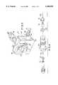
- FIG. 2is a perspective view of a vacuum regulator and cylinder mounting bracket included in the gas feed system shown in FIG. 1.
- FIG. 3is an exploded perspective view of a gas flow control valve assembly included in the vacuum regulator shown in FIG. 2.
- FIG. 4is an enlarged cross section view of a vacuum regulator included in the gas feed system shown in FIG. 1 and showing the vacuum regulator in a "standby" position.
- FIG. 5is a side view of the vacuum regulator shown in FIG. 4.
- FIG. 6is a view similar to FIG. 4 and illustrating the vacuum regulator in an "on" position.
- FIG. 7is a view similar to FIG. 7 and showing the vacuum regulator in the "on" position.
- FIG. 8is a view similar to FIGS. 4 and 6 and showing the vacuum regulator in an "empty" position.
- FIG. 9is a view similar to FIGS. 5 and 7 and showing the vacuum regulator in an "empty" position.
- FIG. 10is a view similar to FIG. 4 and showing the vacuum regulator in an "off" position.
- FIG. 11is a view similar to FIG. 5 and showing the vacuum regulator in the "off" position.
- FIG. 12is an enlarged cross section view of an even drawdown valve included in the gas supply system shown in FIG. 1.
- FIG. 13is an enlarged cross section view of a remote switchover valve included in the gas supply system shown in FIG. 1.
- FIG. 14is a side view of the remote switchover device shown in FIG. 13.
- FIG. 15is a cross section taken along line 15--15 in FIG. 14.
- FIG. 16is an enlarged cross section view of a gas injector included in the gas supply system shown in FIG. 1.
- FIG. 1illustrates a gas feed system embodying the invention and including a plurality of gas cylinders 12.
- the gas cylinders 12are conventional chlorine gas containers.
- the gas feed system 10further includes a vacuum regulator 14 mounted on each cylinder 12, each of the vacuum regulators 14 comprising a vacuum operated valve intended to control the supply of chlorine gas from the gas cylinders 12.
- the vacuum regulators 14are connected through plastic tubing or conduits 16 to supply chlorine gas to a chlorine gas injector 18.
- the chlorine gas injector 18is best shown in FIG. 16 and has a conventional construction.
- the gas injector 18provides for mixing of gas into water flowing through a water supply conduit 20 and facilitates the injection of chlorine gas into the water supply.
- metered gas entering port 22is dissolved at chamber 23 in the water stream flowing through passage 24 from the water supply conduit 20.
- the resultant solutionis discharged through passage 26 to the point of application and the flow of water through the injector 18 generates a vacuum at port 22 and in the tubing or conduit 28. It is this vacuum in the tubing 28 which draws gas through the conduits 16, 30 and 32 into the injector 18 and which operates the vacuum regulators 14 connected to the cylinders 12.
- a rotameter 34is provided between the gas feed cylinders 12 and the injector 18.
- the rotameter 34indicates the volume or rate of the flow of gas through the tubing 32 and 28 to the injector 18.
- the rotameter 34can also include a control valve 36 for controlling the rate of flow through the tubing 32 and 28 to the injector 18.
- the construction of the rotameter 34 and the control valve 36is conventional and will not be described in detail. While in the illustrated arrangement the rotameter 34 is mounted remote from the vacuum regulators 14, in other arrangements a rotameter 34 could be mounted directly on each vacuum regulator to indicate the flow of gas from the individual gas cylinders 12 to the tubing 16.
- the gas supply system 10 shown in FIG. 1further includes a remote switchover device 38 for providing for supply of chlorine gas from a first bank 40 of cylinders during initial operation of the chlorine gas system while maintaining a second bank 42 of cylinders in a standby condition.
- the remote switchover device 38includes a valve which isolates the second bank 42 of cylinders during initial operation of the cylinders and then, when the gas in the first bank 40 of cylinders nears an empty condition, the remote switchover device 38 opens to provide for supply of gas from the second bank 42 of cylinders to the injector 18 while also maintaining the first bank 40 of cylinders in communication with the injector 18 so that all of the gas in the first bank 40 of cylinders can be used.
- the remote switchover device 38can then be manually switched over to connect only the second bank 42 of cylinders to the injector 18 and to isolate the first bank 40 of cylinders.
- the cylinders 12 in the first bank 40can then be removed from the system for refilling and be replaced with full gas containers.
- the remote switchover device 38can then maintain those containers 12 in the standby condition until the second bank 42 of cylinders nears an empty condition.
- each bank of cylinders 40 and 42further includes an even drawdown device 44 connecting the two vacuum regulators 14 in that bank of cylinders to the tubing 30 communicating with the remote switchover device 38 and the injector 18.
- the even drawdown device 44provides for simultaneously even or equal flow of gas from the two cylinders 12 in the bank of cylinders 40 to the remote switchover device 38.
- each vacuum regulator 14each include a housing 46 clampingly mounted to respective ones of the gas cylinders by a yoke clamp or bracket assembly 48.
- the bracket assembly 48 for mounting the regulators 14 to the gas cylindersis conventional and will not be described in detail.
- Each vacuum regulator 14also includes a control knob/indicator 50 which is positionable as shown in FIG. 11 in an "off" position preventing flow of gas through the regulator 14.
- the control knob 50can be manually rotated counterclockwise 180° from the "off" position shown in FIG. 11 to a "standby" position shown in FIG. 2 and FIG. 5.
- the vacuum regulatorincludes a front housing 52 supporting a front cover 54.
- the cover 54in turn supports the control knob 50 for vertical slidable movement between the "standby", “on” and “empty” positions and also for rotation of the control knob 50 to the "off" position.
- the vacuum regulator 14also includes a rear housing 56 fixed to the rear face 58 of the front housing 52.
- a flexible diaphragm 60has a periphery 62 clamped between the front 52 and rear 56 housing.
- the diaphragmincludes a central opening housing a diaphragm backing plate assembly 64 comprised of a diaphragm backing plate 66 and a diaphragm backing plate nut 68 which clampingly engages the inner portion 70 of the diaphragm 60 therebetween.
- the diaphragm backing plate assembly 64is housed in the chamber 72 defined by the rear housing 56, and the diaphragm backing plate assembly 64 is movable with the diaphragm in the chamber 72 between the positions shown in FIGS. 4, 6, 8 and 10.
- the backing plate nut 68is threaded onto a projecting threaded extension 74 of the backing plate 66 such that the backing plate nut 68 clampingly engages the diaphragm 60 and clamps it against the backing plate 66 in fluid tight relation.
- the diaphragm backing plate 66includes a circular groove 76 in its front face 78, the groove 76 housing a projecting circular flange 80 of the front housing 52 such that the diaphragm backing plate assembly 64 is supported for movement in the chamber 72 of the rear housing 56 toward and away from the front housing 52.
- the vacuum tubing 16communicates with the chamber 72 through a port 82, and a coupling 84 (FIG. 2) connects the tubing to the rear housing 56.
- the vacuum in the tubing 16thus draws a vacuum in the chamber 72 defined by the rear housing 56.
- the front face of the diaphragm 60is subjected to atmospheric pressure in the space 86 between the front housing 52 and the diaphragm 60 and diaphragm backing plate 66.
- atmospheric pressure on the diaphragm 60 and diaphragm backing plate 66will tend to force the diaphragm backing plate assembly 64 rearwardly into the rear housing 56.
- the vacuum regulator 14also includes a valve assembly 90 fixed to the rear housing 56 and controlling flow of chlorine gas from the gas cylinder through the inlet port 92 and into the vacuum chamber 72 where it can then be drawn through the port 82 to the vacuum line or tubing 16.
- the valve assembly 90includes a secondary valve housing 94 having one end housed in a bore 96 in a sleeve 98 projecting rearwardly from the rear housing 56.
- a valve housing retainer nut 100is provided to secure the secondary valve housing 94 to the sleeve 98 and rear housing 56.
- the secondary valve housing 94includes a central bore 102 housing a regulator nipple 104 which is threaded into the secondary valve housing 94.
- the regulator nipple 104includes a central bore 106 housing a valve seat 108 and a valve body 110 biased against the valve seat 108 by a first compression spring 112.
- the secondary valve housing 94also houses a secondary valve seat 114 and a secondary valve body 116 biased against that valve seat by a second compression spring 118.
- the second compression spring 118is supported by a stop member 120 slidably housed in the bore 102 in the secondary valve housing 94.
- a rod 122 connected to the first valve bodyengages the stop 120 to provide a connection between the stop 120 and the first valve body 110.
- a second rod 124extends from the secondary valve body 116 and projects forwardly into the vacuum chamber 72 provided by the rear housing.
- the regulator nipple 104also includes the inlet port 92 which communicates through the clamping bracket to the gas cylinder 12.
- the regulatoralso includes an operating pin or shaft 130 threaded into a central bore 132 of the diaphragm backing plate 66 and located centrally with respect to the diaphragm 60.
- the operating pin 130has an end 134 adapted to move with the diaphragm backing plate assembly 64 and to selectively engage the end of the rod 124 extending from the secondary valve body 116 and to provide for movement of the secondary valve body 116 away from the secondary valve seat 114.
- the operating pin 130is threaded into the diaphragm backing plate 66 such that it moves with the diaphragm backing plate 66 in the direction of its longitudinal axis.
- the threads 136 connecting between the operating pin 130 and the diaphragm backing plate assembly 64permits the operating pin 130 to be rotated 180° to an "off" position as shown in FIG. 10 where it is backed out of the diaphragm backing plate 66 such that it cannot engage the rod 124 extending from the secondary valve body 116.
- the opposite end of the operating pin 130includes a cavity or bore 138 housing an operating lever pawl 140 and a compression spring 142.
- the operating lever pawl 140is connected to the operating pin 130 by a cross pin 144 and is supported by the operating pin 130 such that the pawl 140 is resiliently biased by the compression spring 142 into engagement with cam surfaces 142 provided in a recess 145 in the end of a lever 146.
- the cross pin 144 connecting the operating lever pawl 140 to the end of the operating pin 130also pivotally connects the lever 146 to the operating pin 130.
- One of the principle features of the inventionis the construction of the vacuum regulator to provide both a primary and a secondary backup check valve 110 and 116 operated by a single diaphragm 60. In the event one of the check valves fails to close fully, the other check valve will insure complete sealing of the valve assembly. But, while a second check valve 116 can be provided, the construction of the regulator of the invention facilitates the use of only a single diaphragm 60 to provide for movement of both valve assemblies.
- the vacuum regulatoralso includes a pressure relief valve 160 for discharging gas from the regulator in the event that a gas pressure develops in the vacuum chamber 72.
- a gas discharge port 162 in the rear housing 56communicates through a spring biased check valve with a discharge port 166.
- the check valveincludes a flexible diaphragm 164 biased against the port 162 by a pin 168 and a compression spring 170.
- the compression spring 170is backed by a plug 172 threaded into a bore 174 provided in the rear housing.
- the remote switchover valve 38is illustrated in greater detail in FIGS. 13-15 and includes a T-shaped valve body 180 including a pair of inlets 182 and 184 connected to the tubing 30 extending from the banks of chlorine tanks and an outlet port 186 connected by tubing 32 to the rotameter 34 and injector 18.
- the remote switchover device 38includes a reciprocally movable elongated valve member 190 having opposite ends, the opposite ends of the elongated valve member supporting resilient valve cups 192 and 194.
- the elongated valve memberis movable from the intermediate position shown in FIG. 13 to a position wherein the resilient valve cup 192 at one end of the elongated member 190 is engageable with a seat surface 196 to selectively prevent gas flow through the inlet 182.
- the elongated valve member 190is also movable from the intermediate position to the right as shown in FIG. 13 to a position wherein the resilient valve cup 194 sealingly engages a second seat surface 198 to selectively prevent gas flow through the inlet
- a pair of compression springs 200 and 202are provided for biasing the elongated valve member 190 toward the centered or intermediate position shown in FIG. 13.
- a detent deviceis also provided for releasably restraining the elongated valve member 190 in a selected position where the valve member 192 seats against the seat 196 or alternatively for releasably restraining the elongated valve member 190 in a second position wherein the valve member 194 seats against the opposite seat 198 at the opposite end of the valve.
- the detent deviceincludes a rack 204 formed integrally with the central portion of the elongated valve member 190 and a pinion 206 engaging the rack 204.
- the pinion 206is mounted on the end of a manually rotatable shaft 208 (FIG. 15), and a control knob 210 is mounted on the opposite end of the rotatable shaft 208.
- the control knob 210can be manually rotated between a first position wherein the elongated valve member 190 is moved to a position where the cup valve 192 engages the valve seat 196. In that position (FIG. 14) a spring biased detent ball 214 engages a notch 216 provided in a collar 218 mounted on the shaft 208. The detent ball 214 releasably holds the elongated valve member 190 in that position.
- the manual control knob 210can be rotated in the opposite direction wherein a second spring biased detent ball 220 will engage the notch 216 in the collar 218 to hold the elongated valve member 190 in a position wherein the cup valve 194 engages the other valve seat 198.
- control knob 210can be rotated to a position wherein the detent ball 214 will hold the elongated valve member 190 in a position wherein one of the cup valves engages a valve seat to block the flow of gas through that inlet 182.
- the elongated valve memberis held in that position by the force of the detent 214 and by the pressure of gas at inlet 184 from the other bank of cylinders.
- FIG. 12illustrates in greater detail the even drawdown device 44 which includes a pair of housing portions 230 and 232 defining chambers 234 and 236 separated by a diaphragm 238.
- the periphery of the diaphragm 238is clamped between the halves 230 and 232 of the housing and an O-ring 240 provides a fluid tight seal.
- the left housing portion 230 shown in FIG. 12includes a boss or sleeve 242 threadably housing a valve seat holder 244.
- a Teflon valve seat 246is housed in the valve seat holder 244 and a reducing bushing 248 provides for connection of the tubing 16 with bore 249.
- the right housing portion 232includes a boss or sleeve 250 housing a valve seat 252, and a reducing bushing 254 is provided for connecting the other tubing 16 to the inlet bore 256.
- the even drawdown device 44further includes a valve spool 260 having a diaphragm hub 262 clampingly engaging the central portion of the diaphragm 238 such that the valve spool 260 is movable with the diaphragm.
- One end of the valve spool 260includes a valve body 264 selectively engageable with the valve seat 246 and the opposite end of the valve spool 260 includes a second valve body 266 engageable with the second valve seat 252.
- the second valve seat 252includes a plurality of small orifices 268 between the valve body 266 and the valve seat 252 to permit controlled gas flow past the valve seat 252 when the valve member 266 engages the valve seat 252.
- the left and right housing portions 230 and 232are provided with discharge ports 270 and 272, respectively which communicate with the tube 30 providing flow of gas to the rotameter and the injector 18.
- vacuum in the tube 30 communicating with rotameter 34applies a vacuum in the chambers 234 and 236 on both sides of the diaphragm 238, causing gas to be drawn initially through the orifices 268 around the valve body 266.
- the pressure differential caused by gas flow into the right chamber 236 as seen in FIG. 12will create a pressure on the diaphragm 238 causing movement of the valve body 264 away from the valve seat 246 to cause flow of gas into the chamber 234 and until the gas pressure in the chambers on 234 and 236 opposite sides of the diaphragm 238 is equal.
- the gas flow from the tubes 16 communicating with the two gas cylinders 12will thus be equalized to provide for uniform and even flow from those cylinders 12 to the injector 18.
Landscapes
- Engineering & Computer Science (AREA)
- Mechanical Engineering (AREA)
- General Engineering & Computer Science (AREA)
- Filling Or Discharging Of Gas Storage Vessels (AREA)
Abstract
Description
Claims (20)
Priority Applications (2)
| Application Number | Priority Date | Filing Date | Title |
|---|---|---|---|
| US08/981,242US6105598A (en) | 1996-06-14 | 1996-06-14 | Low capacity chlorine gas feed system |
| US09/569,157US6308724B1 (en) | 1998-04-03 | 2000-05-11 | Low capacity chlorine gas feed system |
Applications Claiming Priority (2)
| Application Number | Priority Date | Filing Date | Title |
|---|---|---|---|
| PCT/US1996/010315WO1997000405A1 (en) | 1995-06-15 | 1996-06-14 | Low capacity chlorine gas feed system |
| US08/981,242US6105598A (en) | 1996-06-14 | 1996-06-14 | Low capacity chlorine gas feed system |
Related Child Applications (2)
| Application Number | Title | Priority Date | Filing Date |
|---|---|---|---|
| US09/506,154ContinuationUS6263900B1 (en) | 2000-02-17 | 2000-02-17 | Low capacity chlorine gas feed system |
| US09/569,157Continuation-In-PartUS6308724B1 (en) | 1998-04-03 | 2000-05-11 | Low capacity chlorine gas feed system |
Publications (1)
| Publication Number | Publication Date |
|---|---|
| US6105598Atrue US6105598A (en) | 2000-08-22 |
Family
ID=25528231
Family Applications (1)
| Application Number | Title | Priority Date | Filing Date |
|---|---|---|---|
| US08/981,242Expired - LifetimeUS6105598A (en) | 1996-06-14 | 1996-06-14 | Low capacity chlorine gas feed system |
Country Status (1)
| Country | Link |
|---|---|
| US (1) | US6105598A (en) |
Cited By (16)
| Publication number | Priority date | Publication date | Assignee | Title |
|---|---|---|---|---|
| US6308724B1 (en)* | 1998-04-03 | 2001-10-30 | United States Filter Corporation | Low capacity chlorine gas feed system |
| US20030197146A1 (en)* | 2002-04-22 | 2003-10-23 | Powell Fabrication & Manufacturing, Inc. | Valve closure system and valve closure assembly |
| US20030197147A1 (en)* | 2002-04-22 | 2003-10-23 | Powell Fabrication & Manufacturing, Inc. | Adapters and adapter systems for valve closure systems and valve closure assemblies |
| US6763846B2 (en) | 2001-08-20 | 2004-07-20 | United States Filter Corporation | Fluid distribution device |
| US6957802B2 (en) | 2002-04-22 | 2005-10-25 | Powell Technologies Llc | Valve closure system and valve closure assembly having torque limiting |
| US7013916B1 (en)* | 1997-11-14 | 2006-03-21 | Air Products And Chemicals, Inc. | Sub-atmospheric gas delivery method and apparatus |
| WO2006030923A1 (en) | 2004-09-14 | 2006-03-23 | Tokai Corporation | Pressure regulator |
| US7780833B2 (en) | 2005-07-26 | 2010-08-24 | John Hawkins | Electrochemical ion exchange with textured membranes and cartridge |
| US7959780B2 (en) | 2004-07-26 | 2011-06-14 | Emporia Capital Funding Llc | Textured ion exchange membranes |
| CH704973A1 (en)* | 2011-05-17 | 2012-11-30 | Schwanden Kunststoff | Three-way valve for carrying out flow distribution in heating circuit of passenger vehicle, comprises a rack including a servo motor which is coupled with gear wheel for execution of lifting movement of valve housings joined together |
| US8562803B2 (en) | 2005-10-06 | 2013-10-22 | Pionetics Corporation | Electrochemical ion exchange treatment of fluids |
| FR3008766A1 (en)* | 2013-07-18 | 2015-01-23 | Air Liquide France Ind | METHOD FOR DISPENSING FLUID FROM MULTIPLE FLUID SOURCES |
| US10941904B1 (en)* | 2020-03-04 | 2021-03-09 | Wright Brothers Global Gas, LLC | HP gas supply system and method |
| US11555581B2 (en)* | 2020-03-10 | 2023-01-17 | Hylium Industries, Inc. | Gas discharge apparatus for liquefied hydrogen storage tanks |
| US20230044925A1 (en)* | 2021-08-04 | 2023-02-09 | Lincoln Global, Inc. | Valve with integrated pressure regulator |
| US20230296177A1 (en)* | 2021-08-04 | 2023-09-21 | Lincoln Global, Inc. | Valve with integrated pressure regulator |
Citations (59)
| Publication number | Priority date | Publication date | Assignee | Title |
|---|---|---|---|---|
| CH44650A (en)* | 1908-04-14 | 1909-09-01 | Butzke & Co Ag | Device for regulating the access of cold and hot water to mixing valves |
| US2547823A (en)* | 1944-05-10 | 1951-04-03 | Josephian William | Regulator system |
| US2578042A (en)* | 1948-11-26 | 1951-12-11 | Phillips Petroleum Co | Automatic change-over and indicator valve |
| DE868515C (en)* | 1951-11-09 | 1953-02-26 | Kwikform Ltd | Scaffolding clamp |
| US2630821A (en)* | 1949-04-27 | 1953-03-10 | Weatherhead Co | Automatic changeover valve and signal |
| US2641273A (en)* | 1947-10-18 | 1953-06-09 | C O Two Fire Equipment Co | Changeover valve |
| US2651491A (en)* | 1951-06-12 | 1953-09-08 | Electrol Inc | Shuttle valve |
| US2775980A (en)* | 1957-01-01 | renaudie | ||
| US3001541A (en)* | 1957-03-18 | 1961-09-26 | Weatherhead Co | Automatic regulator assembly |
| US3101734A (en)* | 1960-07-25 | 1963-08-27 | Scott Aviation Corp | Source selecting pressure regulator |
| US3133440A (en)* | 1960-09-14 | 1964-05-19 | Wallace & Tiernan Inc | Stabilizing apparatus for floats for variable flow meters |
| US3141331A (en)* | 1958-10-23 | 1964-07-21 | Metco Inc | Fluid flow meters of the variable orifice type |
| US3154945A (en)* | 1961-05-26 | 1964-11-03 | Fischer & Porter Co | Flowmeter |
| US3171440A (en)* | 1961-01-04 | 1965-03-02 | Pellegrino E Napolitano | Bleeder valve |
| US3181358A (en)* | 1962-10-12 | 1965-05-04 | Fischer & Porter Co | Flowmeter |
| US3220430A (en)* | 1963-05-02 | 1965-11-30 | James F Haskett | Chlorinating system |
| US3342068A (en)* | 1964-11-18 | 1967-09-19 | Fischer & Porter Co | Flowmeter |
| DE2012702A1 (en)* | 1969-04-02 | 1970-10-15 | Pennwalt Corp., Philadelphia, Pa, (V.St.A.) | System for feeding gaseous material into a liquid stream |
| US3542067A (en)* | 1968-08-08 | 1970-11-24 | Amercon Corp | Control valve |
| US3544212A (en)* | 1966-10-12 | 1970-12-01 | Ricoh Kk | Copying device for making vouchers |
| US3592215A (en)* | 1969-12-02 | 1971-07-13 | Fischer & Porter Co | Automatic changeover valve assembly |
| US3646958A (en)* | 1969-09-22 | 1972-03-07 | Niederscheld Gmbh Armaturwerk | Quick-acting valve with rocker-type operating button |
| US3691835A (en)* | 1971-01-20 | 1972-09-19 | Fischer & Porter Co | Variable-area flowmeter with removable metering tube |
| US3779268A (en)* | 1972-06-13 | 1973-12-18 | Pennwalt Corp | Automatic changeover valve for chlorine gas system |
| FR2206280A1 (en)* | 1972-11-10 | 1974-06-07 | Marseille Eaux | Water treatment chlorination plant - with automatic continuity of chlorine supply by switching to standby cylinders |
| US4050305A (en)* | 1976-10-06 | 1977-09-27 | Fischer & Porter Company | Shield and bracket assembly for flowmeter |
| US4099412A (en)* | 1977-06-17 | 1978-07-11 | John Nehrbass | Method of measuring the instantaneous flow rate of urine discharge |
| US4197809A (en)* | 1978-11-27 | 1980-04-15 | Textron, Inc. | Flow responsive device |
| US4202180A (en)* | 1978-10-13 | 1980-05-13 | The Scott & Fetzer Company | Liquefied gas supply system |
| JPS55118109A (en)* | 1979-03-06 | 1980-09-10 | Ebara Corp | Two-fluids ratio flowing amount adjuster |
| US4223557A (en)* | 1979-03-26 | 1980-09-23 | Rockwell International Corporation | Flowmeter |
| US4241749A (en)* | 1978-02-13 | 1980-12-30 | Petursson Sigurdur G | Pressure compensating valve |
| US4245513A (en)* | 1979-02-05 | 1981-01-20 | Will Ross, Inc. | Variable area meter insert unit |
| US4250144A (en)* | 1979-06-14 | 1981-02-10 | Fischer & Porter Company | Chlorine dioxide generating system |
| US4254790A (en)* | 1977-08-30 | 1981-03-10 | Innoventa Aps | Pressure control unit for the control of the pressure of at least one gas depending on the pressure of another gas |
| US4254789A (en)* | 1978-02-23 | 1981-03-10 | Aga Aktiebolag | Apparatus for mixing media, such as gases or liquids |
| US4257279A (en)* | 1979-06-15 | 1981-03-24 | Hivolin Gmbh | Rotameter with float guide members |
| US4324267A (en)* | 1981-03-27 | 1982-04-13 | Huynh Thien Bach | Fluid pressure balancing and mixing valve |
| US4333833A (en)* | 1978-05-08 | 1982-06-08 | Fischer & Porter Co. | In-line disinfectant contactor |
| US4341234A (en)* | 1979-10-08 | 1982-07-27 | Linde Aktiengesellschaft | Method and apparatus for emptying vessels |
| US4380242A (en)* | 1979-10-26 | 1983-04-19 | Texas Gas Transport Company | Method and system for distributing natural gas |
| US4489016A (en)* | 1983-02-11 | 1984-12-18 | Capital Controls Company, Inc. | Apparatus for diffusing gases into liquids |
| US4655246A (en)* | 1983-09-30 | 1987-04-07 | Essex Industries, Inc. | Regulated gas flow control valve |
| US4674526A (en)* | 1986-09-12 | 1987-06-23 | Bellofram Corporation | Switching valve |
| WO1987005133A1 (en)* | 1986-02-13 | 1987-08-27 | Tallinskoe Proizvodstvennoe Upravlenie Vodosnabzhe | Device for automatic dosage of gas into liquid |
| US4752211A (en)* | 1986-09-12 | 1988-06-21 | Sabin Darrel B | Flow proportioning system |
| US4830743A (en)* | 1986-05-02 | 1989-05-16 | Portacel Limited | Water treatment apparatus |
| US4867413A (en)* | 1988-07-14 | 1989-09-19 | Edward Tessler | Gasketless valve, and methods of constructing and utilizing same |
| US4923092A (en)* | 1988-07-20 | 1990-05-08 | The Coca-Cola Company | Binary syrup metering system for beverage dispensing |
| US4986122A (en)* | 1989-11-08 | 1991-01-22 | Hydro Data Inc. | Fluid velocity measurement instrument |
| US4993684A (en)* | 1988-09-14 | 1991-02-19 | Honeywell Lucifer S.A. | Valve for fluid |
| US5046701A (en)* | 1989-11-03 | 1991-09-10 | Cts Corporation | Molded ball/seal |
| US5083546A (en)* | 1991-02-19 | 1992-01-28 | Lectron Products, Inc. | Two-stage high flow purge valve |
| US5095950A (en)* | 1991-04-16 | 1992-03-17 | Hallberg John E | Fluid mixing apparatus with progressive valve means |
| US5151250A (en)* | 1990-03-21 | 1992-09-29 | Conrad Richard H | Automatic purge method for ozone generators |
| US5158748A (en)* | 1990-01-18 | 1992-10-27 | Mochida Pharmaceutical Co., Ltd. | Automated dispensing and diluting system |
| US5189991A (en)* | 1990-12-28 | 1993-03-02 | J. Ebers Pacher | Solenoid distributing valve for volume flow control |
| US5193400A (en)* | 1991-05-10 | 1993-03-16 | Lew Hyok S | Universal rotameter |
| US5320128A (en)* | 1992-11-12 | 1994-06-14 | Chlorinators Incorporated | Chlorinator with reduced number of components |
- 1996
- 1996-06-14USUS08/981,242patent/US6105598A/ennot_activeExpired - Lifetime
Patent Citations (60)
| Publication number | Priority date | Publication date | Assignee | Title |
|---|---|---|---|---|
| US2775980A (en)* | 1957-01-01 | renaudie | ||
| CH44650A (en)* | 1908-04-14 | 1909-09-01 | Butzke & Co Ag | Device for regulating the access of cold and hot water to mixing valves |
| US2547823A (en)* | 1944-05-10 | 1951-04-03 | Josephian William | Regulator system |
| US2641273A (en)* | 1947-10-18 | 1953-06-09 | C O Two Fire Equipment Co | Changeover valve |
| US2578042A (en)* | 1948-11-26 | 1951-12-11 | Phillips Petroleum Co | Automatic change-over and indicator valve |
| US2630821A (en)* | 1949-04-27 | 1953-03-10 | Weatherhead Co | Automatic changeover valve and signal |
| US2651491A (en)* | 1951-06-12 | 1953-09-08 | Electrol Inc | Shuttle valve |
| DE868515C (en)* | 1951-11-09 | 1953-02-26 | Kwikform Ltd | Scaffolding clamp |
| US3001541A (en)* | 1957-03-18 | 1961-09-26 | Weatherhead Co | Automatic regulator assembly |
| US3141331A (en)* | 1958-10-23 | 1964-07-21 | Metco Inc | Fluid flow meters of the variable orifice type |
| US3101734A (en)* | 1960-07-25 | 1963-08-27 | Scott Aviation Corp | Source selecting pressure regulator |
| US3133440A (en)* | 1960-09-14 | 1964-05-19 | Wallace & Tiernan Inc | Stabilizing apparatus for floats for variable flow meters |
| US3171440A (en)* | 1961-01-04 | 1965-03-02 | Pellegrino E Napolitano | Bleeder valve |
| US3154945A (en)* | 1961-05-26 | 1964-11-03 | Fischer & Porter Co | Flowmeter |
| US3181358A (en)* | 1962-10-12 | 1965-05-04 | Fischer & Porter Co | Flowmeter |
| US3220430A (en)* | 1963-05-02 | 1965-11-30 | James F Haskett | Chlorinating system |
| US3342068A (en)* | 1964-11-18 | 1967-09-19 | Fischer & Porter Co | Flowmeter |
| US3544212A (en)* | 1966-10-12 | 1970-12-01 | Ricoh Kk | Copying device for making vouchers |
| US3542067A (en)* | 1968-08-08 | 1970-11-24 | Amercon Corp | Control valve |
| DE2012702A1 (en)* | 1969-04-02 | 1970-10-15 | Pennwalt Corp., Philadelphia, Pa, (V.St.A.) | System for feeding gaseous material into a liquid stream |
| US3604445A (en)* | 1969-04-02 | 1971-09-14 | Pennwalt Corp | System for supplying gaseous material to a flow of liquid |
| US3646958A (en)* | 1969-09-22 | 1972-03-07 | Niederscheld Gmbh Armaturwerk | Quick-acting valve with rocker-type operating button |
| US3592215A (en)* | 1969-12-02 | 1971-07-13 | Fischer & Porter Co | Automatic changeover valve assembly |
| US3691835A (en)* | 1971-01-20 | 1972-09-19 | Fischer & Porter Co | Variable-area flowmeter with removable metering tube |
| US3779268A (en)* | 1972-06-13 | 1973-12-18 | Pennwalt Corp | Automatic changeover valve for chlorine gas system |
| FR2206280A1 (en)* | 1972-11-10 | 1974-06-07 | Marseille Eaux | Water treatment chlorination plant - with automatic continuity of chlorine supply by switching to standby cylinders |
| US4050305A (en)* | 1976-10-06 | 1977-09-27 | Fischer & Porter Company | Shield and bracket assembly for flowmeter |
| US4099412A (en)* | 1977-06-17 | 1978-07-11 | John Nehrbass | Method of measuring the instantaneous flow rate of urine discharge |
| US4254790A (en)* | 1977-08-30 | 1981-03-10 | Innoventa Aps | Pressure control unit for the control of the pressure of at least one gas depending on the pressure of another gas |
| US4241749A (en)* | 1978-02-13 | 1980-12-30 | Petursson Sigurdur G | Pressure compensating valve |
| US4254789A (en)* | 1978-02-23 | 1981-03-10 | Aga Aktiebolag | Apparatus for mixing media, such as gases or liquids |
| US4333833A (en)* | 1978-05-08 | 1982-06-08 | Fischer & Porter Co. | In-line disinfectant contactor |
| US4202180A (en)* | 1978-10-13 | 1980-05-13 | The Scott & Fetzer Company | Liquefied gas supply system |
| US4197809A (en)* | 1978-11-27 | 1980-04-15 | Textron, Inc. | Flow responsive device |
| US4245513A (en)* | 1979-02-05 | 1981-01-20 | Will Ross, Inc. | Variable area meter insert unit |
| JPS55118109A (en)* | 1979-03-06 | 1980-09-10 | Ebara Corp | Two-fluids ratio flowing amount adjuster |
| US4223557A (en)* | 1979-03-26 | 1980-09-23 | Rockwell International Corporation | Flowmeter |
| US4250144A (en)* | 1979-06-14 | 1981-02-10 | Fischer & Porter Company | Chlorine dioxide generating system |
| US4257279A (en)* | 1979-06-15 | 1981-03-24 | Hivolin Gmbh | Rotameter with float guide members |
| US4341234A (en)* | 1979-10-08 | 1982-07-27 | Linde Aktiengesellschaft | Method and apparatus for emptying vessels |
| US4380242A (en)* | 1979-10-26 | 1983-04-19 | Texas Gas Transport Company | Method and system for distributing natural gas |
| US4324267A (en)* | 1981-03-27 | 1982-04-13 | Huynh Thien Bach | Fluid pressure balancing and mixing valve |
| US4489016A (en)* | 1983-02-11 | 1984-12-18 | Capital Controls Company, Inc. | Apparatus for diffusing gases into liquids |
| US4655246A (en)* | 1983-09-30 | 1987-04-07 | Essex Industries, Inc. | Regulated gas flow control valve |
| WO1987005133A1 (en)* | 1986-02-13 | 1987-08-27 | Tallinskoe Proizvodstvennoe Upravlenie Vodosnabzhe | Device for automatic dosage of gas into liquid |
| US4830743A (en)* | 1986-05-02 | 1989-05-16 | Portacel Limited | Water treatment apparatus |
| US4674526A (en)* | 1986-09-12 | 1987-06-23 | Bellofram Corporation | Switching valve |
| US4752211A (en)* | 1986-09-12 | 1988-06-21 | Sabin Darrel B | Flow proportioning system |
| US4867413A (en)* | 1988-07-14 | 1989-09-19 | Edward Tessler | Gasketless valve, and methods of constructing and utilizing same |
| US4923092A (en)* | 1988-07-20 | 1990-05-08 | The Coca-Cola Company | Binary syrup metering system for beverage dispensing |
| US4993684A (en)* | 1988-09-14 | 1991-02-19 | Honeywell Lucifer S.A. | Valve for fluid |
| US5046701A (en)* | 1989-11-03 | 1991-09-10 | Cts Corporation | Molded ball/seal |
| US4986122A (en)* | 1989-11-08 | 1991-01-22 | Hydro Data Inc. | Fluid velocity measurement instrument |
| US5158748A (en)* | 1990-01-18 | 1992-10-27 | Mochida Pharmaceutical Co., Ltd. | Automated dispensing and diluting system |
| US5151250A (en)* | 1990-03-21 | 1992-09-29 | Conrad Richard H | Automatic purge method for ozone generators |
| US5189991A (en)* | 1990-12-28 | 1993-03-02 | J. Ebers Pacher | Solenoid distributing valve for volume flow control |
| US5083546A (en)* | 1991-02-19 | 1992-01-28 | Lectron Products, Inc. | Two-stage high flow purge valve |
| US5095950A (en)* | 1991-04-16 | 1992-03-17 | Hallberg John E | Fluid mixing apparatus with progressive valve means |
| US5193400A (en)* | 1991-05-10 | 1993-03-16 | Lew Hyok S | Universal rotameter |
| US5320128A (en)* | 1992-11-12 | 1994-06-14 | Chlorinators Incorporated | Chlorinator with reduced number of components |
Cited By (27)
| Publication number | Priority date | Publication date | Assignee | Title |
|---|---|---|---|---|
| US7013916B1 (en)* | 1997-11-14 | 2006-03-21 | Air Products And Chemicals, Inc. | Sub-atmospheric gas delivery method and apparatus |
| US6308724B1 (en)* | 1998-04-03 | 2001-10-30 | United States Filter Corporation | Low capacity chlorine gas feed system |
| US6763846B2 (en) | 2001-08-20 | 2004-07-20 | United States Filter Corporation | Fluid distribution device |
| US20040238041A1 (en)* | 2001-08-20 | 2004-12-02 | United States Filter Corporation | Fluid distribution device |
| US6990997B2 (en) | 2001-08-20 | 2006-01-31 | Usfilter Corporation | Fluid distribution device |
| US20030197146A1 (en)* | 2002-04-22 | 2003-10-23 | Powell Fabrication & Manufacturing, Inc. | Valve closure system and valve closure assembly |
| US20030197147A1 (en)* | 2002-04-22 | 2003-10-23 | Powell Fabrication & Manufacturing, Inc. | Adapters and adapter systems for valve closure systems and valve closure assemblies |
| US6908068B2 (en) | 2002-04-22 | 2005-06-21 | Powell Technologies Llc | Adapters and adapter systems for valve closure systems and valve closure assemblies |
| US6957802B2 (en) | 2002-04-22 | 2005-10-25 | Powell Technologies Llc | Valve closure system and valve closure assembly having torque limiting |
| US7959780B2 (en) | 2004-07-26 | 2011-06-14 | Emporia Capital Funding Llc | Textured ion exchange membranes |
| EP2172827A2 (en) | 2004-09-14 | 2010-04-07 | Tokai Corporation | Pressure regulation device |
| US20080314462A1 (en)* | 2004-09-14 | 2008-12-25 | Yasuaki Nakamura | Pressure Regulator |
| EP2172827A3 (en)* | 2004-09-14 | 2010-04-21 | Tokai Corporation | Pressure regulation device |
| WO2006030923A1 (en) | 2004-09-14 | 2006-03-23 | Tokai Corporation | Pressure regulator |
| EP1798623A4 (en)* | 2004-09-14 | 2009-10-28 | Tokai Corp | Pressure regulator |
| US7780833B2 (en) | 2005-07-26 | 2010-08-24 | John Hawkins | Electrochemical ion exchange with textured membranes and cartridge |
| US8293085B2 (en) | 2005-07-26 | 2012-10-23 | Pionetics Corporation | Cartridge having textured membrane |
| US9090493B2 (en) | 2005-10-06 | 2015-07-28 | Pionetics Corporation | Electrochemical ion exchange treatment of fluids |
| US8562803B2 (en) | 2005-10-06 | 2013-10-22 | Pionetics Corporation | Electrochemical ion exchange treatment of fluids |
| CH704973A1 (en)* | 2011-05-17 | 2012-11-30 | Schwanden Kunststoff | Three-way valve for carrying out flow distribution in heating circuit of passenger vehicle, comprises a rack including a servo motor which is coupled with gear wheel for execution of lifting movement of valve housings joined together |
| FR3008766A1 (en)* | 2013-07-18 | 2015-01-23 | Air Liquide France Ind | METHOD FOR DISPENSING FLUID FROM MULTIPLE FLUID SOURCES |
| US10941904B1 (en)* | 2020-03-04 | 2021-03-09 | Wright Brothers Global Gas, LLC | HP gas supply system and method |
| US11519555B2 (en) | 2020-03-04 | 2022-12-06 | Wright Brothers Global Gas, LLC | HP gas supply system and method |
| US11555581B2 (en)* | 2020-03-10 | 2023-01-17 | Hylium Industries, Inc. | Gas discharge apparatus for liquefied hydrogen storage tanks |
| US20230044925A1 (en)* | 2021-08-04 | 2023-02-09 | Lincoln Global, Inc. | Valve with integrated pressure regulator |
| US20230296177A1 (en)* | 2021-08-04 | 2023-09-21 | Lincoln Global, Inc. | Valve with integrated pressure regulator |
| US12196371B2 (en)* | 2021-08-04 | 2025-01-14 | Lincoln Global, Inc. | Valve with integrated pressure regulator |
Similar Documents
| Publication | Publication Date | Title |
|---|---|---|
| US6105598A (en) | Low capacity chlorine gas feed system | |
| US6263900B1 (en) | Low capacity chlorine gas feed system | |
| EP2344792B1 (en) | Shut off valve for a reverse osmosis water filtration system | |
| AU717948B2 (en) | Low capacity chlorine gas feed system | |
| US8186383B2 (en) | Two eductor/four-way selector valve assembly | |
| CA2094683A1 (en) | Steam and water mixing hose station | |
| WO1997034805A1 (en) | Vapor recovery system accommodating orvr vehicles | |
| US6216913B1 (en) | Self-contained pneumatic beverage dispensing system | |
| EP0235437A1 (en) | A fluid control valve | |
| AU728018B2 (en) | A combined pressure reducing and filling valve | |
| US6062427A (en) | Beer keg and pre-mixed beverage tank change-over device | |
| US6308724B1 (en) | Low capacity chlorine gas feed system | |
| AU742099B2 (en) | Low capacity chlorine gas feed system | |
| US4889152A (en) | System for automatically selecting and discharging a pressurized cylinder | |
| US5975152A (en) | Fluid container filling apparatus | |
| US3741248A (en) | Rotary selector valve mechanism | |
| EP1092674A1 (en) | Self-contained pneumatic beverage dispensing system | |
| AU618189B2 (en) | Motorless carbonator pump with gas saving device | |
| GB2145396A (en) | Apparatus for dispensing pressurised liquid | |
| CN120292283B (en) | Double-control mixing faucet valve core and faucet | |
| GB2078867A (en) | Metering system for dispensing beer or other potable carbonated liquids | |
| JP3434675B2 (en) | Switching valve | |
| HK1050916A (en) | Low capacity chlorine gas feed system |
Legal Events
| Date | Code | Title | Description |
|---|---|---|---|
| AS | Assignment | Owner name:WALLACE & TIERNAN, INC., NEW JERSEY Free format text:ASSIGNMENT OF ASSIGNORS INTEREST;ASSIGNORS:CABRERA, MARIO D.;VAN GROUW, ALBERT;STOCKINGER, GREGORY;REEL/FRAME:008539/0682;SIGNING DATES FROM 19970425 TO 19970515 | |
| AS | Assignment | Owner name:UNITED STATES FILTER CORPORATION, CALIFORNIA Free format text:ASSIGNMENT OF ASSIGNORS INTEREST;ASSIGNOR:WALLACE & TIERNAN, INC.;REEL/FRAME:010320/0454 Effective date:19980605 | |
| STCF | Information on status: patent grant | Free format text:PATENTED CASE | |
| FEPP | Fee payment procedure | Free format text:PAYOR NUMBER ASSIGNED (ORIGINAL EVENT CODE: ASPN); ENTITY STATUS OF PATENT OWNER: LARGE ENTITY | |
| FPAY | Fee payment | Year of fee payment:4 | |
| AS | Assignment | Owner name:USFILTER CORPORATION, PENNSYLVANIA Free format text:ASSIGNMENT OF ASSIGNORS INTEREST;ASSIGNOR:UNITED STATES FILTER CORPORATION;REEL/FRAME:015093/0586 Effective date:20040731 | |
| AS | Assignment | Owner name:SIEMENS WATER TECHNOLOGIES HOLDING CORP., PENNSYLV Free format text:CHANGE OF NAME;ASSIGNOR:USFILTER CORPORATION;REEL/FRAME:019407/0869 Effective date:20060901 | |
| FPAY | Fee payment | Year of fee payment:8 | |
| AS | Assignment | Owner name:SIEMENS INDUSTRY, INC., GEORGIA Free format text:MERGER;ASSIGNOR:SIEMENS WATER TECHNOLOGIES HOLDING CORP.;REEL/FRAME:026138/0593 Effective date:20110401 | |
| FPAY | Fee payment | Year of fee payment:12 | |
| AS | Assignment | Owner name:SIEMENS WATER TECHNOLOGIES LLC, GEORGIA Free format text:ASSIGNMENT OF ASSIGNORS INTEREST;ASSIGNOR:SIEMENS INDUSTRY, INC.;REEL/FRAME:031896/0256 Effective date:20130731 | |
| AS | Assignment | Owner name:CREDIT SUISSE AG, CAYMAN ISLANDS BRANCH, AS COLLAT Free format text:INTELLECTUAL PROPERTY SECURITY AGREEMENT (FIRST LIEN);ASSIGNORS:WTG HOLDINGS III CORP.;WTG HOLDINGS II CORP.;SIEMENS TREATED WATER OUTSOURCING CORP.;AND OTHERS;REEL/FRAME:032126/0487 Effective date:20140115 Owner name:CREDIT SUISSE AG, CAYMAN ISLANDS BRANCH, AS COLLAT Free format text:INTELLECTUAL PROPERTY SECURITY AGREEMENT (SECOND LIEN);ASSIGNORS:WTG HOLDINGS III CORP.;WTG HOLDINGS II CORP.;SIEMENS TREATED WATER OUTSOURCING CORP.;AND OTHERS;REEL/FRAME:032126/0430 Effective date:20140115 | |
| AS | Assignment | Owner name:EVOQUA WATER TECHNOLOGIES LLC, GEORGIA Free format text:CHANGE OF NAME;ASSIGNOR:SIEMENS WATER TECHNOLOGIES LLC;REEL/FRAME:032174/0282 Effective date:20140116 | |
| AS | Assignment | Owner name:SIEMENS WATER TECHNOLOGIES LLC, GEORGIA Free format text:RELEASE OF SECURITY INTEREST (REEL/FRAME 032126/0487);ASSIGNOR:CREDIT SUISSE AG, CAYMAN ISLANDS BRANCH, AS COLLATERAL AGENT;REEL/FRAME:055845/0245 Effective date:20210401 Owner name:SIEMENS WATER TECHNOLOGIES LLC, GEORGIA Free format text:RELEASE OF SECURITY INTEREST (REEL/FRAME 032126/0430);ASSIGNOR:CREDIT SUISSE AG, CAYMAN ISLANDS BRANCH, AS COLLATERAL AGENT;REEL/FRAME:055845/0311 Effective date:20210401 |