US6105390A - Apparatus and process for the refrigeration, liquefaction and separation of gases with varying levels of purity - Google Patents
Apparatus and process for the refrigeration, liquefaction and separation of gases with varying levels of purityDownload PDFInfo
- Publication number
- US6105390A US6105390AUS09/212,490US21249098AUS6105390AUS 6105390 AUS6105390 AUS 6105390AUS 21249098 AUS21249098 AUS 21249098AUS 6105390 AUS6105390 AUS 6105390A
- Authority
- US
- United States
- Prior art keywords
- stream
- component
- gas stream
- mixed gas
- heat exchanger
- Prior art date
- Legal status (The legal status is an assumption and is not a legal conclusion. Google has not performed a legal analysis and makes no representation as to the accuracy of the status listed.)
- Expired - Lifetime
Links
- 239000007789gasSubstances0.000titleclaimsabstractdescription355
- 238000000034methodMethods0.000titleclaimsabstractdescription71
- 230000008569processEffects0.000titleclaimsabstractdescription64
- 238000000926separation methodMethods0.000titleabstractdescription16
- 238000005057refrigerationMethods0.000titledescription12
- 239000007788liquidSubstances0.000claimsabstractdescription74
- 238000001816coolingMethods0.000claimsabstractdescription60
- 238000009833condensationMethods0.000claimsabstractdescription13
- 230000005494condensationEffects0.000claimsabstractdescription13
- VNWKTOKETHGBQD-UHFFFAOYSA-NmethaneChemical compoundCVNWKTOKETHGBQD-UHFFFAOYSA-N0.000claimsdescription76
- 239000012071phaseSubstances0.000claimsdescription21
- 239000003345natural gasSubstances0.000claimsdescription19
- 238000012545processingMethods0.000claimsdescription16
- 239000012530fluidSubstances0.000claimsdescription15
- 239000007791liquid phaseSubstances0.000claimsdescription9
- 239000012808vapor phaseSubstances0.000claims5
- 239000003507refrigerantSubstances0.000abstractdescription23
- 230000007423decreaseEffects0.000abstractdescription3
- ATUOYWHBWRKTHZ-UHFFFAOYSA-NPropaneChemical compoundCCCATUOYWHBWRKTHZ-UHFFFAOYSA-N0.000description14
- 230000003292diminished effectEffects0.000description14
- 238000003860storageMethods0.000description13
- 238000010586diagramMethods0.000description8
- 230000008901benefitEffects0.000description7
- 239000001294propaneSubstances0.000description7
- IJGRMHOSHXDMSA-UHFFFAOYSA-NAtomic nitrogenChemical compoundN#NIJGRMHOSHXDMSA-UHFFFAOYSA-N0.000description6
- OFBQJSOFQDEBGM-UHFFFAOYSA-Nn-pentaneNatural productsCCCCCOFBQJSOFQDEBGM-UHFFFAOYSA-N0.000description6
- 229930195733hydrocarbonNatural products0.000description5
- 150000002430hydrocarbonsChemical class0.000description5
- 239000000203mixtureSubstances0.000description5
- 239000000047productSubstances0.000description5
- 239000001273butaneSubstances0.000description4
- 239000003949liquefied natural gasSubstances0.000description4
- IJDNQMDRQITEOD-UHFFFAOYSA-Nn-butaneChemical compoundCCCCIJDNQMDRQITEOD-UHFFFAOYSA-N0.000description4
- XLYOFNOQVPJJNP-UHFFFAOYSA-NwaterSubstancesOXLYOFNOQVPJJNP-UHFFFAOYSA-N0.000description4
- 239000004215Carbon black (E152)Substances0.000description3
- OTMSDBZUPAUEDD-UHFFFAOYSA-NEthaneChemical compoundCCOTMSDBZUPAUEDD-UHFFFAOYSA-N0.000description3
- 238000004519manufacturing processMethods0.000description3
- 229910052757nitrogenInorganic materials0.000description3
- CURLTUGMZLYLDI-UHFFFAOYSA-NCarbon dioxideChemical compoundO=C=OCURLTUGMZLYLDI-UHFFFAOYSA-N0.000description2
- 206010019233HeadachesDiseases0.000description2
- 239000002253acidSubstances0.000description2
- 239000003570airSubstances0.000description2
- QVGXLLKOCUKJST-UHFFFAOYSA-Natomic oxygenChemical compound[O]QVGXLLKOCUKJST-UHFFFAOYSA-N0.000description2
- 230000008859changeEffects0.000description2
- 238000009826distributionMethods0.000description2
- 230000007613environmental effectEffects0.000description2
- 239000012467final productSubstances0.000description2
- 239000000446fuelSubstances0.000description2
- 239000001301oxygenSubstances0.000description2
- 229910052760oxygenInorganic materials0.000description2
- 238000000746purificationMethods0.000description2
- 238000009834vaporizationMethods0.000description2
- 230000008016vaporizationEffects0.000description2
- 238000013022ventingMethods0.000description2
- LSDPWZHWYPCBBB-UHFFFAOYSA-NMethanethiolChemical compoundSCLSDPWZHWYPCBBB-UHFFFAOYSA-N0.000description1
- 238000010521absorption reactionMethods0.000description1
- 239000012080ambient airSubstances0.000description1
- 150000001412aminesChemical class0.000description1
- 239000008346aqueous phaseSubstances0.000description1
- 230000009286beneficial effectEffects0.000description1
- 239000001569carbon dioxideSubstances0.000description1
- 229910002092carbon dioxideInorganic materials0.000description1
- 238000004140cleaningMethods0.000description1
- 239000003245coalSubstances0.000description1
- 238000007906compressionMethods0.000description1
- 230000006835compressionEffects0.000description1
- 239000000356contaminantSubstances0.000description1
- 238000005112continuous flow techniqueMethods0.000description1
- 239000000112cooling gasSubstances0.000description1
- 230000008878couplingEffects0.000description1
- 238000010168coupling processMethods0.000description1
- 238000005859coupling reactionMethods0.000description1
- 230000001419dependent effectEffects0.000description1
- 238000013461designMethods0.000description1
- 238000005516engineering processMethods0.000description1
- 239000001307heliumSubstances0.000description1
- 229910052734heliumInorganic materials0.000description1
- SWQJXJOGLNCZEY-UHFFFAOYSA-Nhelium atomChemical compound[He]SWQJXJOGLNCZEY-UHFFFAOYSA-N0.000description1
- 239000012535impuritySubstances0.000description1
- 238000010348incorporationMethods0.000description1
- 230000007246mechanismEffects0.000description1
- QSHDDOUJBYECFT-UHFFFAOYSA-NmercuryChemical compound[Hg]QSHDDOUJBYECFT-UHFFFAOYSA-N0.000description1
- 229910052753mercuryInorganic materials0.000description1
- 239000002808molecular sieveSubstances0.000description1
- 238000004064recyclingMethods0.000description1
- 230000009467reductionEffects0.000description1
- 239000010865sewageSubstances0.000description1
- URGAHOPLAPQHLN-UHFFFAOYSA-Nsodium aluminosilicateChemical compound[Na+].[Al+3].[O-][Si]([O-])=O.[O-][Si]([O-])=OURGAHOPLAPQHLN-UHFFFAOYSA-N0.000description1
- 239000002594sorbentSubstances0.000description1
- 238000001179sorption measurementMethods0.000description1
- 235000013619trace mineralNutrition0.000description1
- 239000011573trace mineralSubstances0.000description1
- 238000011144upstream manufacturingMethods0.000description1
- 238000010792warmingMethods0.000description1
- 239000002699waste materialSubstances0.000description1
Images


Classifications
- F—MECHANICAL ENGINEERING; LIGHTING; HEATING; WEAPONS; BLASTING
- F25—REFRIGERATION OR COOLING; COMBINED HEATING AND REFRIGERATION SYSTEMS; HEAT PUMP SYSTEMS; MANUFACTURE OR STORAGE OF ICE; LIQUEFACTION SOLIDIFICATION OF GASES
- F25J—LIQUEFACTION, SOLIDIFICATION OR SEPARATION OF GASES OR GASEOUS OR LIQUEFIED GASEOUS MIXTURES BY PRESSURE AND COLD TREATMENT OR BY BRINGING THEM INTO THE SUPERCRITICAL STATE
- F25J1/00—Processes or apparatus for liquefying or solidifying gases or gaseous mixtures
- F25J1/0002—Processes or apparatus for liquefying or solidifying gases or gaseous mixtures characterised by the fluid to be liquefied
- F25J1/0022—Hydrocarbons, e.g. natural gas
- F25J1/0025—Boil-off gases "BOG" from storages
- F—MECHANICAL ENGINEERING; LIGHTING; HEATING; WEAPONS; BLASTING
- F25—REFRIGERATION OR COOLING; COMBINED HEATING AND REFRIGERATION SYSTEMS; HEAT PUMP SYSTEMS; MANUFACTURE OR STORAGE OF ICE; LIQUEFACTION SOLIDIFICATION OF GASES
- F25J—LIQUEFACTION, SOLIDIFICATION OR SEPARATION OF GASES OR GASEOUS OR LIQUEFIED GASEOUS MIXTURES BY PRESSURE AND COLD TREATMENT OR BY BRINGING THEM INTO THE SUPERCRITICAL STATE
- F25J1/00—Processes or apparatus for liquefying or solidifying gases or gaseous mixtures
- F25J1/003—Processes or apparatus for liquefying or solidifying gases or gaseous mixtures characterised by the kind of cold generation within the liquefaction unit for compensating heat leaks and liquid production
- F25J1/0032—Processes or apparatus for liquefying or solidifying gases or gaseous mixtures characterised by the kind of cold generation within the liquefaction unit for compensating heat leaks and liquid production using the feed stream itself or separated fractions from it, i.e. "internal refrigeration"
- F25J1/0035—Processes or apparatus for liquefying or solidifying gases or gaseous mixtures characterised by the kind of cold generation within the liquefaction unit for compensating heat leaks and liquid production using the feed stream itself or separated fractions from it, i.e. "internal refrigeration" by gas expansion with extraction of work
- F25J1/0037—Processes or apparatus for liquefying or solidifying gases or gaseous mixtures characterised by the kind of cold generation within the liquefaction unit for compensating heat leaks and liquid production using the feed stream itself or separated fractions from it, i.e. "internal refrigeration" by gas expansion with extraction of work of a return stream
- F—MECHANICAL ENGINEERING; LIGHTING; HEATING; WEAPONS; BLASTING
- F25—REFRIGERATION OR COOLING; COMBINED HEATING AND REFRIGERATION SYSTEMS; HEAT PUMP SYSTEMS; MANUFACTURE OR STORAGE OF ICE; LIQUEFACTION SOLIDIFICATION OF GASES
- F25J—LIQUEFACTION, SOLIDIFICATION OR SEPARATION OF GASES OR GASEOUS OR LIQUEFIED GASEOUS MIXTURES BY PRESSURE AND COLD TREATMENT OR BY BRINGING THEM INTO THE SUPERCRITICAL STATE
- F25J1/00—Processes or apparatus for liquefying or solidifying gases or gaseous mixtures
- F25J1/003—Processes or apparatus for liquefying or solidifying gases or gaseous mixtures characterised by the kind of cold generation within the liquefaction unit for compensating heat leaks and liquid production
- F25J1/0032—Processes or apparatus for liquefying or solidifying gases or gaseous mixtures characterised by the kind of cold generation within the liquefaction unit for compensating heat leaks and liquid production using the feed stream itself or separated fractions from it, i.e. "internal refrigeration"
- F25J1/004—Processes or apparatus for liquefying or solidifying gases or gaseous mixtures characterised by the kind of cold generation within the liquefaction unit for compensating heat leaks and liquid production using the feed stream itself or separated fractions from it, i.e. "internal refrigeration" by flash gas recovery
- F—MECHANICAL ENGINEERING; LIGHTING; HEATING; WEAPONS; BLASTING
- F25—REFRIGERATION OR COOLING; COMBINED HEATING AND REFRIGERATION SYSTEMS; HEAT PUMP SYSTEMS; MANUFACTURE OR STORAGE OF ICE; LIQUEFACTION SOLIDIFICATION OF GASES
- F25J—LIQUEFACTION, SOLIDIFICATION OR SEPARATION OF GASES OR GASEOUS OR LIQUEFIED GASEOUS MIXTURES BY PRESSURE AND COLD TREATMENT OR BY BRINGING THEM INTO THE SUPERCRITICAL STATE
- F25J1/00—Processes or apparatus for liquefying or solidifying gases or gaseous mixtures
- F25J1/003—Processes or apparatus for liquefying or solidifying gases or gaseous mixtures characterised by the kind of cold generation within the liquefaction unit for compensating heat leaks and liquid production
- F25J1/0032—Processes or apparatus for liquefying or solidifying gases or gaseous mixtures characterised by the kind of cold generation within the liquefaction unit for compensating heat leaks and liquid production using the feed stream itself or separated fractions from it, i.e. "internal refrigeration"
- F25J1/0045—Processes or apparatus for liquefying or solidifying gases or gaseous mixtures characterised by the kind of cold generation within the liquefaction unit for compensating heat leaks and liquid production using the feed stream itself or separated fractions from it, i.e. "internal refrigeration" by vaporising a liquid return stream
- F—MECHANICAL ENGINEERING; LIGHTING; HEATING; WEAPONS; BLASTING
- F25—REFRIGERATION OR COOLING; COMBINED HEATING AND REFRIGERATION SYSTEMS; HEAT PUMP SYSTEMS; MANUFACTURE OR STORAGE OF ICE; LIQUEFACTION SOLIDIFICATION OF GASES
- F25J—LIQUEFACTION, SOLIDIFICATION OR SEPARATION OF GASES OR GASEOUS OR LIQUEFIED GASEOUS MIXTURES BY PRESSURE AND COLD TREATMENT OR BY BRINGING THEM INTO THE SUPERCRITICAL STATE
- F25J1/00—Processes or apparatus for liquefying or solidifying gases or gaseous mixtures
- F25J1/02—Processes or apparatus for liquefying or solidifying gases or gaseous mixtures requiring the use of refrigeration, e.g. of helium or hydrogen ; Details and kind of the refrigeration system used; Integration with other units or processes; Controlling aspects of the process
- F25J1/0201—Processes or apparatus for liquefying or solidifying gases or gaseous mixtures requiring the use of refrigeration, e.g. of helium or hydrogen ; Details and kind of the refrigeration system used; Integration with other units or processes; Controlling aspects of the process using only internal refrigeration means, i.e. without external refrigeration
- F25J1/0202—Processes or apparatus for liquefying or solidifying gases or gaseous mixtures requiring the use of refrigeration, e.g. of helium or hydrogen ; Details and kind of the refrigeration system used; Integration with other units or processes; Controlling aspects of the process using only internal refrigeration means, i.e. without external refrigeration in a quasi-closed internal refrigeration loop
- F—MECHANICAL ENGINEERING; LIGHTING; HEATING; WEAPONS; BLASTING
- F25—REFRIGERATION OR COOLING; COMBINED HEATING AND REFRIGERATION SYSTEMS; HEAT PUMP SYSTEMS; MANUFACTURE OR STORAGE OF ICE; LIQUEFACTION SOLIDIFICATION OF GASES
- F25J—LIQUEFACTION, SOLIDIFICATION OR SEPARATION OF GASES OR GASEOUS OR LIQUEFIED GASEOUS MIXTURES BY PRESSURE AND COLD TREATMENT OR BY BRINGING THEM INTO THE SUPERCRITICAL STATE
- F25J1/00—Processes or apparatus for liquefying or solidifying gases or gaseous mixtures
- F25J1/02—Processes or apparatus for liquefying or solidifying gases or gaseous mixtures requiring the use of refrigeration, e.g. of helium or hydrogen ; Details and kind of the refrigeration system used; Integration with other units or processes; Controlling aspects of the process
- F25J1/0228—Coupling of the liquefaction unit to other units or processes, so-called integrated processes
- F25J1/0232—Coupling of the liquefaction unit to other units or processes, so-called integrated processes integration within a pressure letdown station of a high pressure pipeline system
- F—MECHANICAL ENGINEERING; LIGHTING; HEATING; WEAPONS; BLASTING
- F25—REFRIGERATION OR COOLING; COMBINED HEATING AND REFRIGERATION SYSTEMS; HEAT PUMP SYSTEMS; MANUFACTURE OR STORAGE OF ICE; LIQUEFACTION SOLIDIFICATION OF GASES
- F25J—LIQUEFACTION, SOLIDIFICATION OR SEPARATION OF GASES OR GASEOUS OR LIQUEFIED GASEOUS MIXTURES BY PRESSURE AND COLD TREATMENT OR BY BRINGING THEM INTO THE SUPERCRITICAL STATE
- F25J1/00—Processes or apparatus for liquefying or solidifying gases or gaseous mixtures
- F25J1/02—Processes or apparatus for liquefying or solidifying gases or gaseous mixtures requiring the use of refrigeration, e.g. of helium or hydrogen ; Details and kind of the refrigeration system used; Integration with other units or processes; Controlling aspects of the process
- F25J1/0243—Start-up or control of the process; Details of the apparatus used; Details of the refrigerant compression system used
- F25J1/0244—Operation; Control and regulation; Instrumentation
- F25J1/0254—Operation; Control and regulation; Instrumentation controlling particular process parameter, e.g. pressure, temperature
- F—MECHANICAL ENGINEERING; LIGHTING; HEATING; WEAPONS; BLASTING
- F25—REFRIGERATION OR COOLING; COMBINED HEATING AND REFRIGERATION SYSTEMS; HEAT PUMP SYSTEMS; MANUFACTURE OR STORAGE OF ICE; LIQUEFACTION SOLIDIFICATION OF GASES
- F25J—LIQUEFACTION, SOLIDIFICATION OR SEPARATION OF GASES OR GASEOUS OR LIQUEFIED GASEOUS MIXTURES BY PRESSURE AND COLD TREATMENT OR BY BRINGING THEM INTO THE SUPERCRITICAL STATE
- F25J1/00—Processes or apparatus for liquefying or solidifying gases or gaseous mixtures
- F25J1/02—Processes or apparatus for liquefying or solidifying gases or gaseous mixtures requiring the use of refrigeration, e.g. of helium or hydrogen ; Details and kind of the refrigeration system used; Integration with other units or processes; Controlling aspects of the process
- F25J1/0243—Start-up or control of the process; Details of the apparatus used; Details of the refrigerant compression system used
- F25J1/0257—Construction and layout of liquefaction equipments, e.g. valves, machines
- F25J1/0259—Modularity and arrangement of parts of the liquefaction unit and in particular of the cold box, e.g. pre-fabrication, assembling and erection, dimensions, horizontal layout "plot"
- F—MECHANICAL ENGINEERING; LIGHTING; HEATING; WEAPONS; BLASTING
- F25—REFRIGERATION OR COOLING; COMBINED HEATING AND REFRIGERATION SYSTEMS; HEAT PUMP SYSTEMS; MANUFACTURE OR STORAGE OF ICE; LIQUEFACTION SOLIDIFICATION OF GASES
- F25J—LIQUEFACTION, SOLIDIFICATION OR SEPARATION OF GASES OR GASEOUS OR LIQUEFIED GASEOUS MIXTURES BY PRESSURE AND COLD TREATMENT OR BY BRINGING THEM INTO THE SUPERCRITICAL STATE
- F25J1/00—Processes or apparatus for liquefying or solidifying gases or gaseous mixtures
- F25J1/02—Processes or apparatus for liquefying or solidifying gases or gaseous mixtures requiring the use of refrigeration, e.g. of helium or hydrogen ; Details and kind of the refrigeration system used; Integration with other units or processes; Controlling aspects of the process
- F25J1/0243—Start-up or control of the process; Details of the apparatus used; Details of the refrigerant compression system used
- F25J1/0257—Construction and layout of liquefaction equipments, e.g. valves, machines
- F25J1/0261—Details of cold box insulation, housing and internal structure
- F—MECHANICAL ENGINEERING; LIGHTING; HEATING; WEAPONS; BLASTING
- F25—REFRIGERATION OR COOLING; COMBINED HEATING AND REFRIGERATION SYSTEMS; HEAT PUMP SYSTEMS; MANUFACTURE OR STORAGE OF ICE; LIQUEFACTION SOLIDIFICATION OF GASES
- F25J—LIQUEFACTION, SOLIDIFICATION OR SEPARATION OF GASES OR GASEOUS OR LIQUEFIED GASEOUS MIXTURES BY PRESSURE AND COLD TREATMENT OR BY BRINGING THEM INTO THE SUPERCRITICAL STATE
- F25J1/00—Processes or apparatus for liquefying or solidifying gases or gaseous mixtures
- F25J1/02—Processes or apparatus for liquefying or solidifying gases or gaseous mixtures requiring the use of refrigeration, e.g. of helium or hydrogen ; Details and kind of the refrigeration system used; Integration with other units or processes; Controlling aspects of the process
- F25J1/0243—Start-up or control of the process; Details of the apparatus used; Details of the refrigerant compression system used
- F25J1/0257—Construction and layout of liquefaction equipments, e.g. valves, machines
- F25J1/0275—Construction and layout of liquefaction equipments, e.g. valves, machines adapted for special use of the liquefaction unit, e.g. portable or transportable devices
- F—MECHANICAL ENGINEERING; LIGHTING; HEATING; WEAPONS; BLASTING
- F25—REFRIGERATION OR COOLING; COMBINED HEATING AND REFRIGERATION SYSTEMS; HEAT PUMP SYSTEMS; MANUFACTURE OR STORAGE OF ICE; LIQUEFACTION SOLIDIFICATION OF GASES
- F25J—LIQUEFACTION, SOLIDIFICATION OR SEPARATION OF GASES OR GASEOUS OR LIQUEFIED GASEOUS MIXTURES BY PRESSURE AND COLD TREATMENT OR BY BRINGING THEM INTO THE SUPERCRITICAL STATE
- F25J1/00—Processes or apparatus for liquefying or solidifying gases or gaseous mixtures
- F25J1/02—Processes or apparatus for liquefying or solidifying gases or gaseous mixtures requiring the use of refrigeration, e.g. of helium or hydrogen ; Details and kind of the refrigeration system used; Integration with other units or processes; Controlling aspects of the process
- F25J1/0243—Start-up or control of the process; Details of the apparatus used; Details of the refrigerant compression system used
- F25J1/0279—Compression of refrigerant or internal recycle fluid, e.g. kind of compressor, accumulator, suction drum etc.
- F25J1/0292—Refrigerant compression by cold or cryogenic suction of the refrigerant gas
- F—MECHANICAL ENGINEERING; LIGHTING; HEATING; WEAPONS; BLASTING
- F25—REFRIGERATION OR COOLING; COMBINED HEATING AND REFRIGERATION SYSTEMS; HEAT PUMP SYSTEMS; MANUFACTURE OR STORAGE OF ICE; LIQUEFACTION SOLIDIFICATION OF GASES
- F25J—LIQUEFACTION, SOLIDIFICATION OR SEPARATION OF GASES OR GASEOUS OR LIQUEFIED GASEOUS MIXTURES BY PRESSURE AND COLD TREATMENT OR BY BRINGING THEM INTO THE SUPERCRITICAL STATE
- F25J2205/00—Processes or apparatus using other separation and/or other processing means
- F25J2205/10—Processes or apparatus using other separation and/or other processing means using combined expansion and separation, e.g. in a vortex tube, "Ranque tube" or a "cyclonic fluid separator", i.e. combination of an isentropic nozzle and a cyclonic separator; Centrifugal separation
- F—MECHANICAL ENGINEERING; LIGHTING; HEATING; WEAPONS; BLASTING
- F25—REFRIGERATION OR COOLING; COMBINED HEATING AND REFRIGERATION SYSTEMS; HEAT PUMP SYSTEMS; MANUFACTURE OR STORAGE OF ICE; LIQUEFACTION SOLIDIFICATION OF GASES
- F25J—LIQUEFACTION, SOLIDIFICATION OR SEPARATION OF GASES OR GASEOUS OR LIQUEFIED GASEOUS MIXTURES BY PRESSURE AND COLD TREATMENT OR BY BRINGING THEM INTO THE SUPERCRITICAL STATE
- F25J2220/00—Processes or apparatus involving steps for the removal of impurities
- F25J2220/60—Separating impurities from natural gas, e.g. mercury, cyclic hydrocarbons
- F25J2220/62—Separating low boiling components, e.g. He, H2, N2, Air
- F—MECHANICAL ENGINEERING; LIGHTING; HEATING; WEAPONS; BLASTING
- F25—REFRIGERATION OR COOLING; COMBINED HEATING AND REFRIGERATION SYSTEMS; HEAT PUMP SYSTEMS; MANUFACTURE OR STORAGE OF ICE; LIQUEFACTION SOLIDIFICATION OF GASES
- F25J—LIQUEFACTION, SOLIDIFICATION OR SEPARATION OF GASES OR GASEOUS OR LIQUEFIED GASEOUS MIXTURES BY PRESSURE AND COLD TREATMENT OR BY BRINGING THEM INTO THE SUPERCRITICAL STATE
- F25J2220/00—Processes or apparatus involving steps for the removal of impurities
- F25J2220/60—Separating impurities from natural gas, e.g. mercury, cyclic hydrocarbons
- F25J2220/64—Separating heavy hydrocarbons, e.g. NGL, LPG, C4+ hydrocarbons or heavy condensates in general
- F—MECHANICAL ENGINEERING; LIGHTING; HEATING; WEAPONS; BLASTING
- F25—REFRIGERATION OR COOLING; COMBINED HEATING AND REFRIGERATION SYSTEMS; HEAT PUMP SYSTEMS; MANUFACTURE OR STORAGE OF ICE; LIQUEFACTION SOLIDIFICATION OF GASES
- F25J—LIQUEFACTION, SOLIDIFICATION OR SEPARATION OF GASES OR GASEOUS OR LIQUEFIED GASEOUS MIXTURES BY PRESSURE AND COLD TREATMENT OR BY BRINGING THEM INTO THE SUPERCRITICAL STATE
- F25J2230/00—Processes or apparatus involving steps for increasing the pressure of gaseous process streams
- F25J2230/08—Cold compressor, i.e. suction of the gas at cryogenic temperature and generally without afterstage-cooler
- F—MECHANICAL ENGINEERING; LIGHTING; HEATING; WEAPONS; BLASTING
- F25—REFRIGERATION OR COOLING; COMBINED HEATING AND REFRIGERATION SYSTEMS; HEAT PUMP SYSTEMS; MANUFACTURE OR STORAGE OF ICE; LIQUEFACTION SOLIDIFICATION OF GASES
- F25J—LIQUEFACTION, SOLIDIFICATION OR SEPARATION OF GASES OR GASEOUS OR LIQUEFIED GASEOUS MIXTURES BY PRESSURE AND COLD TREATMENT OR BY BRINGING THEM INTO THE SUPERCRITICAL STATE
- F25J2230/00—Processes or apparatus involving steps for increasing the pressure of gaseous process streams
- F25J2230/30—Compression of the feed stream
- F—MECHANICAL ENGINEERING; LIGHTING; HEATING; WEAPONS; BLASTING
- F25—REFRIGERATION OR COOLING; COMBINED HEATING AND REFRIGERATION SYSTEMS; HEAT PUMP SYSTEMS; MANUFACTURE OR STORAGE OF ICE; LIQUEFACTION SOLIDIFICATION OF GASES
- F25J—LIQUEFACTION, SOLIDIFICATION OR SEPARATION OF GASES OR GASEOUS OR LIQUEFIED GASEOUS MIXTURES BY PRESSURE AND COLD TREATMENT OR BY BRINGING THEM INTO THE SUPERCRITICAL STATE
- F25J2230/00—Processes or apparatus involving steps for increasing the pressure of gaseous process streams
- F25J2230/60—Processes or apparatus involving steps for increasing the pressure of gaseous process streams the fluid being hydrocarbons or a mixture of hydrocarbons
- F—MECHANICAL ENGINEERING; LIGHTING; HEATING; WEAPONS; BLASTING
- F25—REFRIGERATION OR COOLING; COMBINED HEATING AND REFRIGERATION SYSTEMS; HEAT PUMP SYSTEMS; MANUFACTURE OR STORAGE OF ICE; LIQUEFACTION SOLIDIFICATION OF GASES
- F25J—LIQUEFACTION, SOLIDIFICATION OR SEPARATION OF GASES OR GASEOUS OR LIQUEFIED GASEOUS MIXTURES BY PRESSURE AND COLD TREATMENT OR BY BRINGING THEM INTO THE SUPERCRITICAL STATE
- F25J2245/00—Processes or apparatus involving steps for recycling of process streams
- F25J2245/02—Recycle of a stream in general, e.g. a by-pass stream
- F—MECHANICAL ENGINEERING; LIGHTING; HEATING; WEAPONS; BLASTING
- F25—REFRIGERATION OR COOLING; COMBINED HEATING AND REFRIGERATION SYSTEMS; HEAT PUMP SYSTEMS; MANUFACTURE OR STORAGE OF ICE; LIQUEFACTION SOLIDIFICATION OF GASES
- F25J—LIQUEFACTION, SOLIDIFICATION OR SEPARATION OF GASES OR GASEOUS OR LIQUEFIED GASEOUS MIXTURES BY PRESSURE AND COLD TREATMENT OR BY BRINGING THEM INTO THE SUPERCRITICAL STATE
- F25J2290/00—Other details not covered by groups F25J2200/00 - F25J2280/00
- F25J2290/62—Details of storing a fluid in a tank
- Y—GENERAL TAGGING OF NEW TECHNOLOGICAL DEVELOPMENTS; GENERAL TAGGING OF CROSS-SECTIONAL TECHNOLOGIES SPANNING OVER SEVERAL SECTIONS OF THE IPC; TECHNICAL SUBJECTS COVERED BY FORMER USPC CROSS-REFERENCE ART COLLECTIONS [XRACs] AND DIGESTS
- Y10—TECHNICAL SUBJECTS COVERED BY FORMER USPC
- Y10S—TECHNICAL SUBJECTS COVERED BY FORMER USPC CROSS-REFERENCE ART COLLECTIONS [XRACs] AND DIGESTS
- Y10S62/00—Refrigeration
- Y10S62/902—Apparatus
- Y10S62/91—Expander
Definitions
- the present inventionrelates to methods and apparatus for separating, cooling and liquefying component gases from each other in a pressurized mixed gas stream. More particularly, the invention is directed to separation techniques that utilizes some of the components of the mixed gas stream that have already been separated to cool portions of the mixed gas stream that subsequently pass through the apparatus.
- the liquefaction of gasescan be accomplished in a variety of different ways.
- the fundamental methodis to compress the gas and then cool the compressed gas by passing it through a number of consecutively colder heat exchangers.
- a heat exchangeris simply an apparatus or process wherein the gas or fluid to be cooled is exposed to a colder environment which draws heat or energy from the gas or fluid, thereby cooling the gas. Once a gas reaches a sufficiently low temperature for a set pressure, the gas converts to a liquid.
- This cooled refrigerant streamnow flows into the heat exchanger where it is exposed to the main gas stream desired to be cooled.
- the refrigerant streamdraws heat from the main stream, thereby simultaneously cooling the main stream and warming the refrigerant stream.
- the remaining liquidis vaporized to a gas. This gas then returns to the compressor where the process is repeated.
- the main streamBy passing the main gas stream through consecutive heat exchangers having lower and lower temperatures, the main stream can eventually be cooled to a sufficiently low temperature that it converts to a liquid. The liquid is then stored in a pressurized tank.
- Another object of the present inventionis to provide gas processing systems which simultaneously purify the liquefied gas by separating off the other mixed gases.
- Yet another object of the present inventionis to provide the above system which can be operated without the required use of independently operated compressors or refrigeration systems.
- Still another object of the present inventionis to provide the above systems which can be effectively produced to achieve any desired flow capacity and, furthermore, can be manufactured as small mobile units that can be operated at any desired location.
- a gas processing system and method of operationfor separating and cooling components of a pressurized mixed gas stream for subsequent liquefaction of a final or remaining gas stream.
- This inventive system and processcomprises passing a pressurized mixed gas stream through a series of repeated cycles until a final substantially purified gas stream for liquefying is achieved.
- Each cyclecomprises: (1) cooling the pressurized mixed gas stream in a heat exchanger so as to condense one or more of the gas components having the highest condensation point; (2) separating the condensed components from the remaining mixed gas stream in a gas-liquid separator; (3) cooling the separated condensed component stream by passing it through an expander; and then (4) passing the cooled component stream back through the heat exchanger such that the cooled component streams function as the refrigerant for the heat exchanger.
- the component streamthen exits the system for use depending on the type and temperature of gas.
- the above cycleis then repeated for the remaining mixed gas stream so as to draw off the next component gas and further cool the remaining mixed gas stream.
- the processcontinues until all of the unwanted component gases are removed.
- the final gas streamwhich in the case of natural gas will be substantially methane, is then passed through a final heat exchanger.
- the final cooled gas streamis then passed through an expander which decreases the pressure on the gas stream. As the pressure decreases, the stream is cooled causing a portion of the gas stream to liquify within a tank. The portion of the gas which is not liquified is passed back through each of the heat exchangers where it functions as a refrigerant.
- the inventive systemscan be operated solely from the energy produced by dropping the pressure.
- the final expandercan comprise a turbo expander which runs a turbine as the gas is expanded therethrough.
- the electrical or mechanical energy from the turbinecan be used to input energy into the system at any desired location.
- the turbo expandercan run a compressor which is used to increase the pressure of the initial gas stream.
- the present inventionalso envisions that an independently operated compressor can be incorporated into the system.
- the inventive systemhas a variety of benefits over conventional systems. For example, by not needing independently operated compressors or refrigeration systems, the inventive system is simpler and less expensive. Furthermore, the inventive system can be effectively constructed to fit any desired flow parameters at virtually any location. For example, one unique embodiment of the present invention is to incorporate the inventive system onto a movable platform such as a trailer. The movable unit can then be positioned at locations such as a well head, factory, refueling station, or distribution facility.
- an additional benefit of the present inventionis that the system and process can be used to separate off purified component gas streams while simultaneously purifying the final gas stream.
- the systemcan be designed, depending on the gas composition, to condense off substantially pure propane, butane, ethane, and any other gases present for subsequent independent use in their corresponding markets. By removing all the component gases, the final methane gas is also substantially purified. Accordingly, the inventive system and process can also be used to effectively operate gas wells that have historically been capped for having too high of a concentration of undesired components.
- FIG. 1is a schematic flow diagram which illustrates one possible embodiment of the inventive gas processing system
- FIG. 2is a schematic flow diagram of the system shown in FIG. 1 incorporating a turbo expander operating a compressor;
- FIGS. 3-6are schematic flow diagrams of the system shown in FIG. 2 wherein the compressor is compressing alternative gas streams;
- FIG. 7is a schematic flow diagram of an alternative configuration of the system shown in FIG. 1;
- FIG. 8is a schematic flow diagram of one example of one of the cycles shown in FIG. 1;
- FIG. 9is a perspective view of a mobile unit incorporating the system shown in FIG. 1;
- FIG. 10is a schematic flow diagram of the system shown in FIG. 1 incorporating vacuum chambers.
- FIG. 11is a schematic flow diagram of the system shown in FIG. 1 modified to recondense vapor from a storage tank.
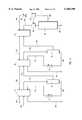
- FIG. 1Depicted in FIG. 1 is one embodiment of a gas processing system 1 incorporating features of the present invention.
- system 1can be adapted for use with any type of mixed gas stream, the operation of system 1 will be discussed with regard to the use of natural gas.
- Natural gasincludes methane and other higher hydrocarbons such as propane, butane, pentane, and ethane.
- system 1is designed to substantially remove the higher hydrocarbons from the natural gas so as to produce a liquified natural gas (LNG) which is predominately methane.
- LNGliquified natural gas
- gas stream 100is delivered to gas processing system 1 at a pressure greater than 250 psia, preferably greater than 500 psia, and more preferably greater than 1000 psia.
- pressurescan be obtained naturally from a gas well or obtained by adding energy through the use of one or more compressors. Since a high pressure drop is helpful in the liquefaction process, initial higher pressures are typically preferred.
- gas stream 100Some of the factors which influence the required initial pressure of gas stream 100 are the required output pressures and temperatures, the gas mixture composition, and the heat capacities of the different components. Since gas stream 100 is pressurized, it inherently contains cooling potential. With a simple expansion, the entire stream can be cooled. Additionally, once the stream's components are condensed to a liquid phase and separated, that liquid phase stream can also be expanded for cooling.
- the refrigerant for first heat exchanger 10comes from two cooling streams, a first component stream 110 and final gas stream 108. In alternative embodiments, only one of streams 108 and 110 are necessary for cooling within first heat exchanger 10.
- Mixed gas stream 100leaves first heat exchanger 10 as mixed gas stream 114 containing the condensed first component.
- each of the different process streamsundergo changes in their physical characteristics as the streams are heated, cooled, expanded, evaporated, separated, and/or otherwise manipulated within the inventive system.
- Mixed gas stream 114next travels to a gas-liquid separator 14.
- gas-liquid separator 14Such separators come in a variety of different configurations and may or may not be part of heat exchanger 10.
- Separator 14separates the condensed first component from the remaining gases.
- the gas phasenow at least mostly devoid of the first component, exits separator 14 as a diminished mixed gas stream 116.
- the condensed first componentexits separator 14 as a liquid first gas stream 118.
- Liquid first component stream 118is next cooled by passing through an expander 12.
- an expanderis broadly intended to include all apparatus and method steps which can be used to obtain a pressure reduction in either a liquid or gas.
- an expandercan include a plate having a hole in it or conventional valves such as the Joule-Thompson valve.
- Other types of expandersinclude vortex tubes and turbo expanders.
- the present inventionalso appreciates that there are a variety of expanders that are currently being developed or that will be developed in the future and such devices are also encompassed within the term “expander.”
- Expander 12produces a pressure drop between liquid first component stream 118 entering expander 12 and first component stream 110 exiting expander 12.
- first component stream 110expands to produce and adiabatic cooling of stream 110.
- some or all of stream 110can be vaporized.
- This vaporizationis a type of evaporization in that the stream goes through a phase change from a liquid to a vapor. To some extent, the greater the pressure drop, the lower the temperature of stream 110, and the higher the extent of cooling or vaporization.
- First component stream 110exits first heat exchanger 10 as first component stream 102.
- stream 102can be looped back through the system, as discussed later, to produce further cooling. Otherwise, stream 102 can be disposed of, collected, or otherwise transported off site for use consistent with the type of gas.
- first component stream 102from mixed gas stream 100 produces a variety of benefits. For example, depending on the controlled temperatures of first heat exchanger 10, stream 102 can be removed as a substantially pure discrete gas. That is, where propane is the highest hydrocarbon gas in gas stream 100, the propane can be removed as stream 102 in a substantially pure state for subsequent use or sale. Simultaneously, by drawing off first component stream 118, diminished mixed gas stream 116 has been refined in that it now has a higher concentration of methane.
- the above processis next repeated for mixed gas stream 116 so as to remove the next component gas. That is, diminished mixed gas stream 116 passes through one or more second heat exchangers 20 and is cooled to a temperature below the highest condensation point of the remaining gas components. As a result, a second component condenses within mixed gas stream 124 leaving second heat exchanger 20.
- the refrigerant for second heat exchanger 20is also obtained from two cooling streams, a second component stream 120 and final gas stream 108.
- the condensed second componentis removed as a liquid from mixed gas stream 124 in a second gas-liquid separator 24.
- the gas phasenow at least mostly devoid of the second component, exits second separator 24 as a second diminish mixed gas stream 126.
- the condensed second componentexists second separator 24 as a liquid second component stream 128.
- second component stream 128passes through a second expander 22 where it experiences a pressure drop.
- second component stream 120 leaving expander 22is cooled and, in most embodiments, at least partially vaporized.
- second component stream 120passes through second heat exchanger 20 where it functions as a refrigerant for withdrawing heat from mixed gas stream 116. After passing through second heat exchanger 20, the second component stream exits as second component stream 104.
- stream 104can also be cycled back through the system for further cooling or removed for independent use.
- the second diminished mixed gas stream 126is further cooled by passing through a third heat exchanger 30 to create a final mixed gas stream 132.
- the refrigerant for third heat exchanger 30comprises final gas stream 108.
- Final mixed gas stream 132can, depending on the desired final product, be a single purified component which has the lowest condensation point of any of the components in original gas stream 100, or be a combination of the gas components.
- final mixed gas stream 132is substantially pure methane in a gas phase.
- gas stream 132is passed through an expander 32 to produce a pressure drop.
- the pressure dropcools gas stream 132 causing at least a portion of gas stream 132 to liquify as it travels into a final gas-liquid separator 34.
- the liquefied gasexits separator as final liquid stream 106 while the gas or vapor is within separator 34 exits as final gas stream 108.
- final gas stream 108passes back through each of heat exchangers 10, 20 and 30 where it functions as a refrigerant.
- Final gas stream 108can then be recycled into the system, transported off site, or connected with municipal gas line for conventional home or business use.
- final gas stream 108has a pressure less than about 100 psia and more preferably less than about 50 psia.
- the operation of liquefaction system 1 produce a liquid final product stream 106can be accomplished without the addition energy, such as the use of a compressor. Operation of the system in this manner, however, typically requires that the input pressure of gas stream 100 be greater than about 500 psia and preferably greater than about 1000 psia. In order to obtain a high percentage of liquid methane, it is preferred to have an input pressure of 1500 psia and more preferably greater than about 2000 psia. Where the well head pressures are insufficient, the present invention envisions that a compressor can be used to increase the pressure of initial mixed gas stream 100.
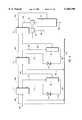
- FIGS. 2-7Depicted in FIGS. 2-7 are alternative embodiments of system 1. The different embodiments are not intended to be limiting but rather examples intending to demonstrate the flexibility of the present invention.
- initial gas stream 100is initially passed through a compressor 80 to increase the pressure thereat prior to entering the system.
- expander 32 of FIG. 1is comprised of a turbo expander 82.
- Turbo expander 82facilitates expansion of mixed gas stream 132 while simultaneously rotating a turbine.
- the turbinecan be used to generate mechanical or electrical energy which runs compressor 80. Accordingly, by using compressor 80 which is run by turbo expander 82, the initial gas pressure can be increased without the required addition of an external energy source.
- additional energy sourcessuch as an external motor, can also be used to independently drive or assist in driving compressor 80.
- compressed gas stream 100' leaving compressor 80is passed through a preliminary heat exchanger 83.
- Heat exchanger 83can comprise a variety of configurations which depend on the surrounding environment.
- heat exchanger 83can be a conventional ambient air cooled heat exchanger or, were available, different water sources such as a river or lake can be used as the cooling element of heat exchanger 83.
- the preliminary cooled gas stream 101travels from heat exchanger 83 to first heat exchanger 10 where the process as discussed with regard to FIG. 1 is performed.
- compressor 80can be used for compressing the gas stream at any point along the system.
- compressor 80can be replaced with a refrigeration system which is also run by turbo expander 82.
- the refrigeration systemcan be used for further cooling the gas stream at any point along the system.
- first component stream 102 and second component stream 104are fed into compressor 80 which is again operated by turbo expander 82.
- the resulting compressed gas stream 150is fed back into initial mixed gas stream 100, thereby recycling the various component streams for use as refrigerants.
- feeding compressed gas stream 150 into stream 100can also lower the temperature of stream 100.
- compressor 80is configured to compress final gas stream 108 leaving gas-liquid separator 34.
- Compressor 80is again driven by turbo expander 82 having final mixed gas stream 132 passing therethrough.
- Final gas stream 108 leaving compressor 80is cooled by passing through an expander 84. Cooled gas stream 108 then passes through each of heat exchangers 10, 20 and 30 in series, as previously discusses with regard to FIG. 1, to facilitate the cooling of the mixed gas streams passing therethrough.
- final gas stream 108is again compressed by compressor 80 driven by turbo expander 82.
- separate expanders 84a, 84b and 84care coupled with heat exchangers 10, 20, and 30, respectively.
- Final gas stream 108is connected to each of expanders 84a, 84b and 84c in parallel. As a result, the cooling of final gas stream 108 by expanders 84a, 84b and 84c is equally effective for each of heat exchangers 10, 20, and 30.
- Final gas stream 108is typically connected to an output line for feeding residential and commercial gas needs. Connecting to such a line, however, requires that the gas have a minimal pressure which is typically greater than about 40 psia. As depicted in FIG. 6, where the pressure of final gas stream 108 has dropped below the minimal required pressure, final gas stream 108 can be fed through compressor 80 operated by turbo expander 82. The departing gas stream 152 would then have the required minimal pressure for connection to the output line. Depending on the quality of gas required, first component stream 102 and second component stream 104 can be feed into final gas stream 108.
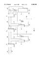
- a pressurized mixed gas stream 200is cooled in a first heat exchanger 40 with a final gas stream 202.
- first heat exchanger 40causes the condensation of a first component in mixed gas stream 200.
- the condensed first componentis separated from the remaining gases of the resulting mixed gas stream 204 in a liquid-gas separator 42.
- the gas phase componentsexit separator 42 as a diminished mixed gas stream 206.
- the condensed first componentexits separator 42 as a liquid first component stream 208.
- the liquid first component stream 208is cooled by passing through a first expander 44 to produce a cooled first component stream 210.
- first component stream 210is used as a refrigerant in the heat exchanger of the next separation cycle.
- first component stream 210cools diminished mixed gas stream 206 as it passes through a second heat exchanger 50. Additional cooling can also be obtained in second heat exchanger 50 by using final gas stream 202.
- First component stream 210exits second heat exchangers 50 as first component stream 214.
- the diminished mixed gas stream 206is cooled in second heat exchanger 50, thereby creating a mixed gas stream 216 with a condensed second component.
- mixed gas stream 216follows the same process steps as described above for mixed gas stream 204. The process continues with the separation of the condensed second component from the remaining gas phase components in a second gas-liquid separator 52. The remaining gas phase components exit the second separation 52 as a second diminished mixed gas stream 218. The condensed second component exits the second separator 52 as a liquid second component stream 220. Liquid second component stream 220 passes through a second expander 54 to create a cooled second component stream 222.
- FIG. 8shows a more detailed flow diagram for a single process cycle of cooling a mixed gas stream to produce condensed component; separation of the condensed component from the remaining gas; expansion of liquid component, and using the cooled, expanded component for further cooling. It is to be understood that this recital of equipment and methods is not to be considered limiting, but is presented to illustrate and set forth one example.
- a diminished mixed gas stream 300exits a first gas-liquid separator 70 and is cooled by passing through a first heat exchanger 72.
- a final gas stream 302functions as the refrigerant for first heat exchanger 72.
- the now cooled diminished mixed gas stream 304is further cooled in a second heat exchanger 74.
- a cooled component stream 306functions as the refrigerant for second heat exchanger 74.
- the first and second heat exchangers 72 and 74 of FIG. 8correspond to heat exchanger 10 of FIG. 1.
- Second heat exchanger 74cools diminished mixed gas stream 304 to below the condensation point of the stream's highest component, thereby creating a gas and liquid mixture which is separated in a second gas-liquid separator 76.
- the gas phasethen exits second separator 76 to enter into the next cycle.
- the liquid condensed componentis expanded through a Joule-Thompson expansion valve 78 which not only evaporates the liquid, but further cools the stream with expansion creating the cooled component stream 306.
- component stream 306cools the diminished mixed gas stream 304 in second heat exchanger 74, it exits the process as a component stream 310.
- FIGS. 1-8 and variations thereoncan be used in a variety of different environments and configurations to perform different functions.
- one of the basic operations of the inventive systemis in the production of liquefied natural gas (LNG).
- LNGis becoming increasing more important as an alternative fuel for running automobiles and other types of motorized equipment or machines.
- the inventive systemcan be selectively designed and manufactured to accommodate small, medium, and large capacities.
- one preferred application for the inventive systemis in the liquefaction of natural gas received from conventional transport pipelines.
- Inlet natural gas streamstypically have pipeline pressures from between about 500 psi to about 900 psi and the product liquid natural gas streams may have flow volumes between about 1,000 gallons/day to about 10,000 gallons/day.
- the inventive systemcan also be used in peak demand storage.
- pipeline gas at between about 500 psi to about 900 psiis liquefied and put in large tanks for use at peak demand times.
- the product liquid natural gas stream volumesare very large, typically ranging from about 70,000 gallons/day to about 100,000 gallons/day.
- Similar to peak demand storageis export storage. In export storage, large quantities of LNG are produced and stored prior to over seas shipping. In this embodiment even larger volumes of liquid natural gas is produced, typically between about 1 million gallons/day to about 3 million gallons/day.
- the inventive systemis easily and effectively manufactured on a small scale.
- the inventive systemis a relatively simple continuous flow process which requires minimal, and often no, external energy sources such as independently operated refrigeration systems or compressors. Rather, the inventive system can often be run solely on the well head or gas line pressure.
- the inventive systemcan be manufactured to produce LNG at small factories, refueling stations, distribution points, and other desired locations.
- the inventive systemscan also be designed to produce on demand so that large storage tanks are not required.
- a further benefit of the self powered property of the systemis that it is well suited for operation in remote locations.
- the systemcan be positioned at individual well heads for processing the gas. This is beneficial in that the system can use the high well head pressure, often above 2,000 psi, to facility operation of the system.
- the systemcan remove undesired impurities from the natural gas as discrete components while dropping the pressure of the resulting purified gas, typically below 1,000 psi, for feeding into a conventional transport pipeline.
- final mixed stream 132 in FIG. 1pass through expander 33 for liquefaction
- final mixed stream 132can be fed directly into a transport pipeline.
- final gas stream 108can be connected to the transport pipeline.
- Mobile unit 95which can be easily transported to different locations for use as required.
- Mobile unit 95includes system 1 being mounted on a movable trailer 96 having wheels 97.
- unit 95may not have wheels, but is just movable or transportable.
- Mobile unit 95can be used at virtually any location.
- mobile unit 95can be positioned in a gas field for direct coupling with a gas well 98.
- each heat exchanger 10, 20, and 30is enclosed in a single vacuum chamber identified by dashed line 322.
- a vacuum chamber identified by dashed line 324can also enclose expanders 12 and 22 along with gas-liquid separators 14 and 24.
- vacuum chamberscan be designed to enclose any desired elements. The incorporation of such vacuum chambers is practically impossible in large systems but produces substantial savings in the inventive small systems.
- An additional use for the inventive systemis in gas purification.
- many productive gas wellsare found that have high concentrations of unwanted gases such as nitrogen.
- unwanted gasessuch as nitrogen.
- small mobile systemscan be positioned directly at the well head.
- the various condensation cyclescan be used to draw off the unwanted gas or gasses which are then vented or otherwise disposed.
- the remaining purified gassescan then be transported for use.
- the desired gasescan be selectively drawn off in various condensations cycles while the final remaining gas is left as the unwanted product.
- the inventive systemcan be used in capturing vapor loss in large storage facilities or tanks. That is, LNG is often stored in large tanks for use at peak demand or for overseas shipping on tankers. As the LNG warms within the stored tanks, a portion of the gas vaporizes. To prevent failure of the tank, the gas must slowly be vented so as not to exceed critical pressure limits of the storage tank. Venting the natural gas to the atmosphere, however, raises some safety and environmental concerns. Furthermore, it results in a loss of gas.
- FIG. 11Depicted in FIG. 11 is a large storage tank 312 holding LNG 314.
- a vaporized gas stream 316leaves tank 312 and is compressed by compressor 80.
- the processcan be run by the pressure build-up within tank 312.
- turbo expander 82with the returning gas to run compressor 80.
- an outside generator or other electrical sourceis used to run compressor 80.
- Compressed gas stream 318exits compressor 80 and returns to heat exchanger 10 where the cooling process begins substantially as described with regard to FIG. 1.
- the component gas streams 102 and 104are simply returned to tank 312.
Landscapes
- Engineering & Computer Science (AREA)
- Physics & Mathematics (AREA)
- Mechanical Engineering (AREA)
- Thermal Sciences (AREA)
- General Engineering & Computer Science (AREA)
- Chemical & Material Sciences (AREA)
- Chemical Kinetics & Catalysis (AREA)
- General Chemical & Material Sciences (AREA)
- Oil, Petroleum & Natural Gas (AREA)
- Separation By Low-Temperature Treatments (AREA)
Abstract
Description
Claims (30)
Priority Applications (1)
| Application Number | Priority Date | Filing Date | Title |
|---|---|---|---|
| US09/212,490US6105390A (en) | 1997-12-16 | 1998-12-16 | Apparatus and process for the refrigeration, liquefaction and separation of gases with varying levels of purity |
Applications Claiming Priority (2)
| Application Number | Priority Date | Filing Date | Title |
|---|---|---|---|
| US6969897P | 1997-12-16 | 1997-12-16 | |
| US09/212,490US6105390A (en) | 1997-12-16 | 1998-12-16 | Apparatus and process for the refrigeration, liquefaction and separation of gases with varying levels of purity |
Publications (1)
| Publication Number | Publication Date |
|---|---|
| US6105390Atrue US6105390A (en) | 2000-08-22 |
Family
ID=22090653
Family Applications (2)
| Application Number | Title | Priority Date | Filing Date |
|---|---|---|---|
| US09/212,490Expired - LifetimeUS6105390A (en) | 1997-12-16 | 1998-12-16 | Apparatus and process for the refrigeration, liquefaction and separation of gases with varying levels of purity |
| US09/643,420Expired - LifetimeUS6425263B1 (en) | 1992-12-16 | 2001-08-23 | Apparatus and process for the refrigeration, liquefaction and separation of gases with varying levels of purity |
Family Applications After (1)
| Application Number | Title | Priority Date | Filing Date |
|---|---|---|---|
| US09/643,420Expired - LifetimeUS6425263B1 (en) | 1992-12-16 | 2001-08-23 | Apparatus and process for the refrigeration, liquefaction and separation of gases with varying levels of purity |
Country Status (6)
| Country | Link |
|---|---|
| US (2) | US6105390A (en) |
| EP (1) | EP1062466B1 (en) |
| JP (1) | JP2002508498A (en) |
| AU (1) | AU1937999A (en) |
| CA (1) | CA2315014C (en) |
| WO (1) | WO1999031447A2 (en) |
Cited By (37)
| Publication number | Priority date | Publication date | Assignee | Title |
|---|---|---|---|---|
| US6581409B2 (en) | 2001-05-04 | 2003-06-24 | Bechtel Bwxt Idaho, Llc | Apparatus for the liquefaction of natural gas and methods related to same |
| US6711914B2 (en)* | 2001-05-11 | 2004-03-30 | Institut Francais Du Petrole | Process for pretreating a natural gas containing acid compounds |
| US20040083888A1 (en)* | 2002-11-01 | 2004-05-06 | Qualls Wesley R. | Heat integration system for natural gas liquefaction |
| US20040194499A1 (en)* | 2003-04-01 | 2004-10-07 | Grenfell Conrad Q. | Method and apparatus for pressurizing a gas |
| US20040248999A1 (en)* | 2003-03-27 | 2004-12-09 | Briscoe Michael D. | Integrated processing of natural gas into liquid products |
| US6931889B1 (en) | 2002-04-19 | 2005-08-23 | Abb Lummus Global, Randall Gas Technologies | Cryogenic process for increased recovery of hydrogen |
| EP1629369A4 (en)* | 2003-06-02 | 2006-06-14 | Disney Entpr Inc | System and method of programmatic window control for consumer video players |
| RU2279019C2 (en)* | 2003-06-11 | 2006-06-27 | Государственное образовательное учреждение Воронежская государственная технологическая академия | Liquefied gas cooling apparatus |
| US20060213223A1 (en)* | 2001-05-04 | 2006-09-28 | Battelle Energy Alliance, Llc | Apparatus for the liquefaction of natural gas and methods relating to same |
| US20060218939A1 (en)* | 2001-05-04 | 2006-10-05 | Battelle Energy Alliance, Llc | Apparatus for the liquefaction of natural gas and methods relating to same |
| US7219512B1 (en) | 2001-05-04 | 2007-05-22 | Battelle Energy Alliance, Llc | Apparatus for the liquefaction of natural gas and methods relating to same |
| US20070137246A1 (en)* | 2001-05-04 | 2007-06-21 | Battelle Energy Alliance, Llc | Systems and methods for delivering hydrogen and separation of hydrogen from a carrier medium |
| US20070227186A1 (en)* | 2004-09-24 | 2007-10-04 | Alferov Vadim I | Systems and methods for low-temperature gas separation |
| US20080264076A1 (en)* | 2007-04-25 | 2008-10-30 | Black & Veatch Corporation | System and method for recovering and liquefying boil-off gas |
| US20090145167A1 (en)* | 2007-12-06 | 2009-06-11 | Battelle Energy Alliance, Llc | Methods, apparatuses and systems for processing fluid streams having multiple constituents |
| US20090205367A1 (en)* | 2008-02-15 | 2009-08-20 | Price Brian C | Combined synthesis gas separation and LNG production method and system |
| US7637122B2 (en) | 2001-05-04 | 2009-12-29 | Battelle Energy Alliance, Llc | Apparatus for the liquefaction of a gas and methods relating to same |
| US7642292B2 (en) | 2005-03-16 | 2010-01-05 | Fuelcor Llc | Systems, methods, and compositions for production of synthetic hydrocarbon compounds |
| US20110094262A1 (en)* | 2009-10-22 | 2011-04-28 | Battelle Energy Alliance, Llc | Complete liquefaction methods and apparatus |
| US8061413B2 (en) | 2007-09-13 | 2011-11-22 | Battelle Energy Alliance, Llc | Heat exchangers comprising at least one porous member positioned within a casing |
| CN102564066A (en)* | 2012-02-10 | 2012-07-11 | 南京柯德超低温技术有限公司 | Low-temperature device for separating and purifying gas based on small-sized low-temperature refrigerating machine |
| US8545580B2 (en) | 2006-07-18 | 2013-10-01 | Honeywell International Inc. | Chemically-modified mixed fuels, methods of production and uses thereof |
| US8671699B2 (en) | 2005-05-19 | 2014-03-18 | Black & Veatch Holding Company | Method and system for vaporizing liquefied natural gas with optional co-production of electricity |
| US8899074B2 (en) | 2009-10-22 | 2014-12-02 | Battelle Energy Alliance, Llc | Methods of natural gas liquefaction and natural gas liquefaction plants utilizing multiple and varying gas streams |
| WO2014204817A3 (en)* | 2013-06-18 | 2015-02-19 | Pioneer Energy, Inc. | Systems and methods for separating alkane gases with applications to raw natural gas processing |
| US9217603B2 (en) | 2007-09-13 | 2015-12-22 | Battelle Energy Alliance, Llc | Heat exchanger and related methods |
| US9254448B2 (en) | 2007-09-13 | 2016-02-09 | Battelle Energy Alliance, Llc | Sublimation systems and associated methods |
| US9574713B2 (en) | 2007-09-13 | 2017-02-21 | Battelle Energy Alliance, Llc | Vaporization chambers and associated methods |
| US9574822B2 (en) | 2014-03-17 | 2017-02-21 | Black & Veatch Corporation | Liquefied natural gas facility employing an optimized mixed refrigerant system |
| US9777960B2 (en) | 2010-12-01 | 2017-10-03 | Black & Veatch Holding Company | NGL recovery from natural gas using a mixed refrigerant |
| US10113127B2 (en) | 2010-04-16 | 2018-10-30 | Black & Veatch Holding Company | Process for separating nitrogen from a natural gas stream with nitrogen stripping in the production of liquefied natural gas |
| US10139157B2 (en) | 2012-02-22 | 2018-11-27 | Black & Veatch Holding Company | NGL recovery from natural gas using a mixed refrigerant |
| US10563913B2 (en) | 2013-11-15 | 2020-02-18 | Black & Veatch Holding Company | Systems and methods for hydrocarbon refrigeration with a mixed refrigerant cycle |
| US10571190B2 (en) | 2015-01-05 | 2020-02-25 | Mitsubishi Heavy Industries Thermal Systems, Ltd. | Liquefied gas cooling apparatus |
| US10655911B2 (en) | 2012-06-20 | 2020-05-19 | Battelle Energy Alliance, Llc | Natural gas liquefaction employing independent refrigerant path |
| US11911732B2 (en) | 2020-04-03 | 2024-02-27 | Nublu Innovations, Llc | Oilfield deep well processing and injection facility and methods |
| US12025373B2 (en) | 2020-08-16 | 2024-07-02 | Gtuit, Llc | System and method for treating associated gas |
Families Citing this family (20)
| Publication number | Priority date | Publication date | Assignee | Title |
|---|---|---|---|---|
| MY122625A (en)* | 1999-12-17 | 2006-04-29 | Exxonmobil Upstream Res Co | Process for making pressurized liquefied natural gas from pressured natural gas using expansion cooling |
| US6668582B2 (en)* | 2001-04-20 | 2003-12-30 | American Air Liquide | Apparatus and methods for low pressure cryogenic cooling |
| GB0120272D0 (en) | 2001-08-21 | 2001-10-10 | Gasconsult Ltd | Improved process for liquefaction of natural gases |
| GB0129607D0 (en)* | 2001-12-11 | 2002-01-30 | Sui See C | Exhaust eater energy generator |
| US20080264099A1 (en)* | 2007-04-24 | 2008-10-30 | Conocophillips Company | Domestic gas product from an lng facility |
| US8020406B2 (en)* | 2007-11-05 | 2011-09-20 | David Vandor | Method and system for the small-scale production of liquified natural gas (LNG) from low-pressure gas |
| US20090301108A1 (en)* | 2008-06-05 | 2009-12-10 | Alstom Technology Ltd | Multi-refrigerant cooling system with provisions for adjustment of refrigerant composition |
| CN101644527B (en)* | 2009-08-26 | 2011-12-28 | 四川空分设备(集团)有限责任公司 | Refrigeration system and liquefaction system for liquefaction process of natural gas |
| US20110094261A1 (en)* | 2009-10-22 | 2011-04-28 | Battelle Energy Alliance, Llc | Natural gas liquefaction core modules, plants including same and related methods |
| CA2790961C (en) | 2012-05-11 | 2019-09-03 | Jose Lourenco | A method to recover lpg and condensates from refineries fuel gas streams. |
| US20140075985A1 (en) | 2012-09-17 | 2014-03-20 | N. Wayne Mckay | Process for optimizing removal of condensable components from a fluid |
| CA2790182C (en)* | 2012-09-17 | 2014-04-29 | Gas Liquids Engineering Ltd. | Process for optimizing removal of condensable components from a fluid |
| CA2798057C (en) | 2012-12-04 | 2019-11-26 | Mackenzie Millar | A method to produce lng at gas pressure letdown stations in natural gas transmission pipeline systems |
| CA2813260C (en) | 2013-04-15 | 2021-07-06 | Mackenzie Millar | A method to produce lng |
| WO2014173599A2 (en)* | 2013-04-22 | 2014-10-30 | Shell Internationale Research Maatschappij B.V. | Method and apparatus for producing a liquefied hydrocarbon stream |
| CA2909614C (en)* | 2013-04-22 | 2021-02-16 | Shell Internationale Research Maatschappij B.V. | Method and apparatus for producing a liquefied hydrocarbon stream |
| RU2557880C1 (en)* | 2014-07-04 | 2015-07-27 | Общество с ограниченной ответственностью "Газпром добыча Уренгой" | Method of hydrocarbon gas preparation for transportation |
| CA2958091C (en) | 2014-08-15 | 2021-05-18 | 1304338 Alberta Ltd. | A method of removing carbon dioxide during liquid natural gas production from natural gas at gas pressure letdown stations |
| CN108431184B (en) | 2015-09-16 | 2021-03-30 | 1304342阿尔伯塔有限公司 | Method for preparing natural gas at a gas decompression station to produce liquid natural gas (LNG) |
| CN107166871A (en)* | 2017-06-01 | 2017-09-15 | 西安交通大学 | Using the re-liquefied system of natural gas vaporization gas of twin-stage mixed-refrigerant cycle |
Citations (28)
| Publication number | Priority date | Publication date | Assignee | Title |
|---|---|---|---|---|
| US2494120A (en)* | 1947-09-23 | 1950-01-10 | Phillips Petroleum Co | Expansion refrigeration system and method |
| US3292380A (en)* | 1964-04-28 | 1966-12-20 | Coastal States Gas Producing C | Method and equipment for treating hydrocarbon gases for pressure reduction and condensate recovery |
| US3323315A (en)* | 1964-07-15 | 1967-06-06 | Conch Int Methane Ltd | Gas liquefaction employing an evaporating and gas expansion refrigerant cycles |
| US3362173A (en)* | 1965-02-16 | 1968-01-09 | Lummus Co | Liquefaction process employing cascade refrigeration |
| US3416324A (en)* | 1967-06-12 | 1968-12-17 | Judson S. Swearingen | Liquefaction of a gaseous mixture employing work expanded gaseous mixture as refrigerant |
| US3548606A (en)* | 1968-07-08 | 1970-12-22 | Phillips Petroleum Co | Serial incremental refrigerant expansion for gas liquefaction |
| US3596473A (en)* | 1967-12-27 | 1971-08-03 | Messer Griesheim Gmbh | Liquefaction process for gas mixtures by means of fractional condensation |
| US3628340A (en)* | 1969-11-13 | 1971-12-21 | Hydrocarbon Research Inc | Process for cryogenic purification of hydrogen |
| US3724226A (en)* | 1971-04-20 | 1973-04-03 | Gulf Research Development Co | Lng expander cycle process employing integrated cryogenic purification |
| US4128410A (en)* | 1974-02-25 | 1978-12-05 | Gulf Oil Corporation | Natural gas treatment |
| US4334902A (en)* | 1979-12-12 | 1982-06-15 | Compagnie Francaise D'etudes Et De Construction "Technip" | Method of and system for refrigerating a fluid to be cooled down to a low temperature |
| US4453956A (en)* | 1981-07-07 | 1984-06-12 | Snamprogetti S.P.A. | Recovering condensables from natural gas |
| US4609390A (en)* | 1984-05-14 | 1986-09-02 | Wilson Richard A | Process and apparatus for separating hydrocarbon gas into a residue gas fraction and a product fraction |
| US4645522A (en)* | 1984-06-22 | 1987-02-24 | Dobrotwir Nicholas G | Process for selectively separating petroleum fractions |
| US4846862A (en)* | 1988-09-06 | 1989-07-11 | Air Products And Chemicals, Inc. | Reliquefaction of boil-off from liquefied natural gas |
| US4970867A (en)* | 1989-08-21 | 1990-11-20 | Air Products And Chemicals, Inc. | Liquefaction of natural gas using process-loaded expanders |
| US5327730A (en)* | 1993-05-12 | 1994-07-12 | American Gas & Technology, Inc. | Method and apparatus for liquifying natural gas for fuel for vehicles and fuel tank for use therewith |
| US5375422A (en)* | 1991-04-09 | 1994-12-27 | Butts; Rayburn C. | High efficiency nitrogen rejection unit |
| US5390499A (en)* | 1993-10-27 | 1995-02-21 | Liquid Carbonic Corporation | Process to increase natural gas methane content |
| US5450728A (en)* | 1993-11-30 | 1995-09-19 | Air Products And Chemicals, Inc. | Recovery of volatile organic compounds from gas streams |
| US5537827A (en)* | 1995-06-07 | 1996-07-23 | Low; William R. | Method for liquefaction of natural gas |
| US5600969A (en)* | 1995-12-18 | 1997-02-11 | Phillips Petroleum Company | Process and apparatus to produce a small scale LNG stream from an existing NGL expander plant demethanizer |
| US5615561A (en)* | 1994-11-08 | 1997-04-01 | Williams Field Services Company | LNG production in cryogenic natural gas processing plants |
| US5655388A (en)* | 1995-07-27 | 1997-08-12 | Praxair Technology, Inc. | Cryogenic rectification system for producing high pressure gaseous oxygen and liquid product |
| US5669234A (en)* | 1996-07-16 | 1997-09-23 | Phillips Petroleum Company | Efficiency improvement of open-cycle cascaded refrigeration process |
| US5718126A (en)* | 1995-10-11 | 1998-02-17 | Institut Francais Du Petrole | Process and device for liquefying and for processing a natural gas |
| US5755114A (en)* | 1997-01-06 | 1998-05-26 | Abb Randall Corporation | Use of a turboexpander cycle in liquefied natural gas process |
| US5836173A (en)* | 1997-05-01 | 1998-11-17 | Praxair Technology, Inc. | System for producing cryogenic liquid |
Family Cites Families (8)
| Publication number | Priority date | Publication date | Assignee | Title |
|---|---|---|---|---|
| US2209534A (en)* | 1937-10-06 | 1940-07-30 | Standard Oil Dev Co | Method for producing gas wells |
| US2937503A (en)* | 1955-09-19 | 1960-05-24 | Nat Tank Co | Turbo-expander-compressor units |
| EP0318504B1 (en) | 1986-08-06 | 1991-06-12 | Linde Aktiengesellschaft | Process for separating higher hydrocarbons from a gas mixture |
| DE8810093U1 (en) | 1988-08-08 | 1988-10-06 | Siemens AG, 1000 Berlin und 8000 München | Locking device for data processing equipment |
| WO1994001727A1 (en)* | 1992-07-10 | 1994-01-20 | Tovarischestvo S Ogranichennoi Otvetstvennostju Diler | Method of gas cooling and a gas cooler |
| US5414188A (en)* | 1993-05-05 | 1995-05-09 | Ha; Bao | Method and apparatus for the separation of C4 hydrocarbons from gaseous mixtures containing the same |
| FR2711779B1 (en)* | 1993-10-26 | 1995-12-08 | Air Liquide | Method and installation for cryogenic hydrogen purification. |
| US5983665A (en) | 1998-03-03 | 1999-11-16 | Air Products And Chemicals, Inc. | Production of refrigerated liquid methane |
- 1998
- 1998-12-16EPEP98964201Apatent/EP1062466B1/ennot_activeExpired - Lifetime
- 1998-12-16AUAU19379/99Apatent/AU1937999A/ennot_activeAbandoned
- 1998-12-16WOPCT/US1998/027232patent/WO1999031447A2/enactiveApplication Filing
- 1998-12-16CACA002315014Apatent/CA2315014C/ennot_activeExpired - Lifetime
- 1998-12-16USUS09/212,490patent/US6105390A/ennot_activeExpired - Lifetime
- 1998-12-16JPJP2000539305Apatent/JP2002508498A/ennot_activeWithdrawn
- 2001
- 2001-08-23USUS09/643,420patent/US6425263B1/ennot_activeExpired - Lifetime
Patent Citations (28)
| Publication number | Priority date | Publication date | Assignee | Title |
|---|---|---|---|---|
| US2494120A (en)* | 1947-09-23 | 1950-01-10 | Phillips Petroleum Co | Expansion refrigeration system and method |
| US3292380A (en)* | 1964-04-28 | 1966-12-20 | Coastal States Gas Producing C | Method and equipment for treating hydrocarbon gases for pressure reduction and condensate recovery |
| US3323315A (en)* | 1964-07-15 | 1967-06-06 | Conch Int Methane Ltd | Gas liquefaction employing an evaporating and gas expansion refrigerant cycles |
| US3362173A (en)* | 1965-02-16 | 1968-01-09 | Lummus Co | Liquefaction process employing cascade refrigeration |
| US3416324A (en)* | 1967-06-12 | 1968-12-17 | Judson S. Swearingen | Liquefaction of a gaseous mixture employing work expanded gaseous mixture as refrigerant |
| US3596473A (en)* | 1967-12-27 | 1971-08-03 | Messer Griesheim Gmbh | Liquefaction process for gas mixtures by means of fractional condensation |
| US3548606A (en)* | 1968-07-08 | 1970-12-22 | Phillips Petroleum Co | Serial incremental refrigerant expansion for gas liquefaction |
| US3628340A (en)* | 1969-11-13 | 1971-12-21 | Hydrocarbon Research Inc | Process for cryogenic purification of hydrogen |
| US3724226A (en)* | 1971-04-20 | 1973-04-03 | Gulf Research Development Co | Lng expander cycle process employing integrated cryogenic purification |
| US4128410A (en)* | 1974-02-25 | 1978-12-05 | Gulf Oil Corporation | Natural gas treatment |
| US4334902A (en)* | 1979-12-12 | 1982-06-15 | Compagnie Francaise D'etudes Et De Construction "Technip" | Method of and system for refrigerating a fluid to be cooled down to a low temperature |
| US4453956A (en)* | 1981-07-07 | 1984-06-12 | Snamprogetti S.P.A. | Recovering condensables from natural gas |
| US4609390A (en)* | 1984-05-14 | 1986-09-02 | Wilson Richard A | Process and apparatus for separating hydrocarbon gas into a residue gas fraction and a product fraction |
| US4645522A (en)* | 1984-06-22 | 1987-02-24 | Dobrotwir Nicholas G | Process for selectively separating petroleum fractions |
| US4846862A (en)* | 1988-09-06 | 1989-07-11 | Air Products And Chemicals, Inc. | Reliquefaction of boil-off from liquefied natural gas |
| US4970867A (en)* | 1989-08-21 | 1990-11-20 | Air Products And Chemicals, Inc. | Liquefaction of natural gas using process-loaded expanders |
| US5375422A (en)* | 1991-04-09 | 1994-12-27 | Butts; Rayburn C. | High efficiency nitrogen rejection unit |
| US5327730A (en)* | 1993-05-12 | 1994-07-12 | American Gas & Technology, Inc. | Method and apparatus for liquifying natural gas for fuel for vehicles and fuel tank for use therewith |
| US5390499A (en)* | 1993-10-27 | 1995-02-21 | Liquid Carbonic Corporation | Process to increase natural gas methane content |
| US5450728A (en)* | 1993-11-30 | 1995-09-19 | Air Products And Chemicals, Inc. | Recovery of volatile organic compounds from gas streams |
| US5615561A (en)* | 1994-11-08 | 1997-04-01 | Williams Field Services Company | LNG production in cryogenic natural gas processing plants |
| US5537827A (en)* | 1995-06-07 | 1996-07-23 | Low; William R. | Method for liquefaction of natural gas |
| US5655388A (en)* | 1995-07-27 | 1997-08-12 | Praxair Technology, Inc. | Cryogenic rectification system for producing high pressure gaseous oxygen and liquid product |
| US5718126A (en)* | 1995-10-11 | 1998-02-17 | Institut Francais Du Petrole | Process and device for liquefying and for processing a natural gas |
| US5600969A (en)* | 1995-12-18 | 1997-02-11 | Phillips Petroleum Company | Process and apparatus to produce a small scale LNG stream from an existing NGL expander plant demethanizer |
| US5669234A (en)* | 1996-07-16 | 1997-09-23 | Phillips Petroleum Company | Efficiency improvement of open-cycle cascaded refrigeration process |
| US5755114A (en)* | 1997-01-06 | 1998-05-26 | Abb Randall Corporation | Use of a turboexpander cycle in liquefied natural gas process |
| US5836173A (en)* | 1997-05-01 | 1998-11-17 | Praxair Technology, Inc. | System for producing cryogenic liquid |
Cited By (59)
| Publication number | Priority date | Publication date | Assignee | Title |
|---|---|---|---|---|
| US20070137246A1 (en)* | 2001-05-04 | 2007-06-21 | Battelle Energy Alliance, Llc | Systems and methods for delivering hydrogen and separation of hydrogen from a carrier medium |
| US20060218939A1 (en)* | 2001-05-04 | 2006-10-05 | Battelle Energy Alliance, Llc | Apparatus for the liquefaction of natural gas and methods relating to same |
| US7591150B2 (en) | 2001-05-04 | 2009-09-22 | Battelle Energy Alliance, Llc | Apparatus for the liquefaction of natural gas and methods relating to same |
| US7219512B1 (en) | 2001-05-04 | 2007-05-22 | Battelle Energy Alliance, Llc | Apparatus for the liquefaction of natural gas and methods relating to same |
| US20060213223A1 (en)* | 2001-05-04 | 2006-09-28 | Battelle Energy Alliance, Llc | Apparatus for the liquefaction of natural gas and methods relating to same |
| US7594414B2 (en) | 2001-05-04 | 2009-09-29 | Battelle Energy Alliance, Llc | Apparatus for the liquefaction of natural gas and methods relating to same |
| US6886362B2 (en) | 2001-05-04 | 2005-05-03 | Bechtel Bwxt Idaho Llc | Apparatus for the liquefaction of natural gas and methods relating to same |
| US7637122B2 (en) | 2001-05-04 | 2009-12-29 | Battelle Energy Alliance, Llc | Apparatus for the liquefaction of a gas and methods relating to same |
| US6962061B2 (en) | 2001-05-04 | 2005-11-08 | Battelle Energy Alliance, Llc | Apparatus for the liquefaction of natural gas and methods relating to same |
| US6581409B2 (en) | 2001-05-04 | 2003-06-24 | Bechtel Bwxt Idaho, Llc | Apparatus for the liquefaction of natural gas and methods related to same |
| US6711914B2 (en)* | 2001-05-11 | 2004-03-30 | Institut Francais Du Petrole | Process for pretreating a natural gas containing acid compounds |
| EP1867940A3 (en)* | 2002-02-27 | 2016-03-09 | Bechtel BWXT Idaho, LLC | Apparatus for the liquefaction of natural gas and methods relating to same |
| EP1478874A4 (en)* | 2002-02-27 | 2007-09-12 | Bechtel Bwxt Idaho Llc | Apparatus for the liquefaction of natural gas and methods relating to same |
| US6931889B1 (en) | 2002-04-19 | 2005-08-23 | Abb Lummus Global, Randall Gas Technologies | Cryogenic process for increased recovery of hydrogen |
| US6793712B2 (en) | 2002-11-01 | 2004-09-21 | Conocophillips Company | Heat integration system for natural gas liquefaction |
| US20040083888A1 (en)* | 2002-11-01 | 2004-05-06 | Qualls Wesley R. | Heat integration system for natural gas liquefaction |
| US20040248999A1 (en)* | 2003-03-27 | 2004-12-09 | Briscoe Michael D. | Integrated processing of natural gas into liquid products |
| US7168265B2 (en)* | 2003-03-27 | 2007-01-30 | Bp Corporation North America Inc. | Integrated processing of natural gas into liquid products |
| US20040194499A1 (en)* | 2003-04-01 | 2004-10-07 | Grenfell Conrad Q. | Method and apparatus for pressurizing a gas |
| US7065974B2 (en) | 2003-04-01 | 2006-06-27 | Grenfell Conrad Q | Method and apparatus for pressurizing a gas |
| EP1629369A4 (en)* | 2003-06-02 | 2006-06-14 | Disney Entpr Inc | System and method of programmatic window control for consumer video players |
| RU2279019C2 (en)* | 2003-06-11 | 2006-06-27 | Государственное образовательное учреждение Воронежская государственная технологическая академия | Liquefied gas cooling apparatus |
| US20070227186A1 (en)* | 2004-09-24 | 2007-10-04 | Alferov Vadim I | Systems and methods for low-temperature gas separation |
| US20110054044A1 (en)* | 2005-03-16 | 2011-03-03 | Severinsky Alexander J | Systems, methods, and compositions for production of synthetic hydrocarbon compounds |
| US7642292B2 (en) | 2005-03-16 | 2010-01-05 | Fuelcor Llc | Systems, methods, and compositions for production of synthetic hydrocarbon compounds |
| US7863340B2 (en) | 2005-03-16 | 2011-01-04 | Fuelcor Llc | Systems, methods, and compositions for production of synthetic hydrocarbon compounds |
| US8093305B2 (en) | 2005-03-16 | 2012-01-10 | Fuelcor, Llc | Systems, methods, and compositions for production of synthetic hydrocarbon compounds |
| US8114916B2 (en) | 2005-03-16 | 2012-02-14 | Fuelcor, Llc | Systems, methods, and compositions for production of synthetic hydrocarbon compounds |
| US8168143B2 (en) | 2005-03-16 | 2012-05-01 | Fuelcor, Llc | Systems, methods, and compositions for production of synthetic hydrocarbon compounds |
| US8671699B2 (en) | 2005-05-19 | 2014-03-18 | Black & Veatch Holding Company | Method and system for vaporizing liquefied natural gas with optional co-production of electricity |
| US8980802B2 (en) | 2006-07-18 | 2015-03-17 | Honeywell International Inc. | Chemically-modified mixed fuels, methods of production and uses thereof |
| US8545580B2 (en) | 2006-07-18 | 2013-10-01 | Honeywell International Inc. | Chemically-modified mixed fuels, methods of production and uses thereof |
| US20080264076A1 (en)* | 2007-04-25 | 2008-10-30 | Black & Veatch Corporation | System and method for recovering and liquefying boil-off gas |
| US8650906B2 (en) | 2007-04-25 | 2014-02-18 | Black & Veatch Corporation | System and method for recovering and liquefying boil-off gas |
| US8061413B2 (en) | 2007-09-13 | 2011-11-22 | Battelle Energy Alliance, Llc | Heat exchangers comprising at least one porous member positioned within a casing |
| US8544295B2 (en) | 2007-09-13 | 2013-10-01 | Battelle Energy Alliance, Llc | Methods of conveying fluids and methods of sublimating solid particles |
| US9574713B2 (en) | 2007-09-13 | 2017-02-21 | Battelle Energy Alliance, Llc | Vaporization chambers and associated methods |
| US9254448B2 (en) | 2007-09-13 | 2016-02-09 | Battelle Energy Alliance, Llc | Sublimation systems and associated methods |
| US9217603B2 (en) | 2007-09-13 | 2015-12-22 | Battelle Energy Alliance, Llc | Heat exchanger and related methods |
| US20090145167A1 (en)* | 2007-12-06 | 2009-06-11 | Battelle Energy Alliance, Llc | Methods, apparatuses and systems for processing fluid streams having multiple constituents |
| US9243842B2 (en) | 2008-02-15 | 2016-01-26 | Black & Veatch Corporation | Combined synthesis gas separation and LNG production method and system |
| US20090205367A1 (en)* | 2008-02-15 | 2009-08-20 | Price Brian C | Combined synthesis gas separation and LNG production method and system |
| US8899074B2 (en) | 2009-10-22 | 2014-12-02 | Battelle Energy Alliance, Llc | Methods of natural gas liquefaction and natural gas liquefaction plants utilizing multiple and varying gas streams |
| US20110094262A1 (en)* | 2009-10-22 | 2011-04-28 | Battelle Energy Alliance, Llc | Complete liquefaction methods and apparatus |
| US8555672B2 (en) | 2009-10-22 | 2013-10-15 | Battelle Energy Alliance, Llc | Complete liquefaction methods and apparatus |
| US10113127B2 (en) | 2010-04-16 | 2018-10-30 | Black & Veatch Holding Company | Process for separating nitrogen from a natural gas stream with nitrogen stripping in the production of liquefied natural gas |
| US9777960B2 (en) | 2010-12-01 | 2017-10-03 | Black & Veatch Holding Company | NGL recovery from natural gas using a mixed refrigerant |
| CN102564066A (en)* | 2012-02-10 | 2012-07-11 | 南京柯德超低温技术有限公司 | Low-temperature device for separating and purifying gas based on small-sized low-temperature refrigerating machine |
| CN102564066B (en)* | 2012-02-10 | 2013-10-16 | 南京柯德超低温技术有限公司 | Low-temperature device for separating and purifying gas based on small-sized low-temperature refrigerating machine |
| US10139157B2 (en) | 2012-02-22 | 2018-11-27 | Black & Veatch Holding Company | NGL recovery from natural gas using a mixed refrigerant |
| US10655911B2 (en) | 2012-06-20 | 2020-05-19 | Battelle Energy Alliance, Llc | Natural gas liquefaction employing independent refrigerant path |
| US9719024B2 (en) | 2013-06-18 | 2017-08-01 | Pioneer Energy, Inc. | Systems and methods for controlling, monitoring, and operating remote oil and gas field equipment over a data network with applications to raw natural gas processing and flare gas capture |
| US10000704B2 (en) | 2013-06-18 | 2018-06-19 | Pioneer Energy Inc. | Systems and methods for controlling, monitoring, and operating remote oil and gas field equipment over a data network with applications to raw natural gas processing and flare gas capture |
| WO2014204817A3 (en)* | 2013-06-18 | 2015-02-19 | Pioneer Energy, Inc. | Systems and methods for separating alkane gases with applications to raw natural gas processing |
| US10563913B2 (en) | 2013-11-15 | 2020-02-18 | Black & Veatch Holding Company | Systems and methods for hydrocarbon refrigeration with a mixed refrigerant cycle |
| US9574822B2 (en) | 2014-03-17 | 2017-02-21 | Black & Veatch Corporation | Liquefied natural gas facility employing an optimized mixed refrigerant system |
| US10571190B2 (en) | 2015-01-05 | 2020-02-25 | Mitsubishi Heavy Industries Thermal Systems, Ltd. | Liquefied gas cooling apparatus |
| US11911732B2 (en) | 2020-04-03 | 2024-02-27 | Nublu Innovations, Llc | Oilfield deep well processing and injection facility and methods |
| US12025373B2 (en) | 2020-08-16 | 2024-07-02 | Gtuit, Llc | System and method for treating associated gas |
Also Published As
| Publication number | Publication date |
|---|---|
| WO1999031447A3 (en) | 1999-08-26 |
| WO1999031447A2 (en) | 1999-06-24 |
| CA2315014A1 (en) | 1999-06-24 |
| US6425263B1 (en) | 2002-07-30 |
| CA2315014C (en) | 2007-06-19 |
| EP1062466A2 (en) | 2000-12-27 |
| JP2002508498A (en) | 2002-03-19 |
| EP1062466A4 (en) | 2002-11-20 |
| EP1062466B1 (en) | 2012-07-25 |
| AU1937999A (en) | 1999-07-05 |
Similar Documents
| Publication | Publication Date | Title |
|---|---|---|
| US6105390A (en) | Apparatus and process for the refrigeration, liquefaction and separation of gases with varying levels of purity | |
| US6631626B1 (en) | Natural gas liquefaction with improved nitrogen removal | |
| US6640586B1 (en) | Motor driven compressor system for natural gas liquefaction | |
| JP5006515B2 (en) | Improved drive and compressor system for natural gas liquefaction | |
| US6196021B1 (en) | Industrial gas pipeline letdown liquefaction system | |
| US6253574B1 (en) | Method for liquefying a stream rich in hydrocarbons | |
| AU733788B2 (en) | Use of a turboexpander cycle in liquefied natural gas process | |
| US5139547A (en) | Production of liquid nitrogen using liquefied natural gas as sole refrigerant | |
| KR101302310B1 (en) | Semi-closed loop lng process | |
| US20070240449A1 (en) | Method for producing liquefied natural gas | |
| US20090084132A1 (en) | Method for producing liquefied natural gas | |
| US20230366620A1 (en) | System and Method for Cooling Fluids Containing Hydrogen or Helium | |
| AU2003287356B2 (en) | Motor driven compressor system for natural gas liquefaction | |
| MXPA99006305A (en) | Use of a turboexpander cycle in liquefied natural gas process |
Legal Events
| Date | Code | Title | Description |
|---|---|---|---|
| AS | Assignment | Owner name:LOCKHEED MARTIN IDAHO TECHOLOGIES, IDAHO Free format text:ASSIGNMENT OF ASSIGNORS INTEREST;ASSIGNORS:BINGHAM, DENNIS N.;WILDING, BRUCE M.;MCKELLAR, MICHAEL G.;REEL/FRAME:009661/0204;SIGNING DATES FROM 19981215 TO 19981216 | |
| AS | Assignment | Owner name:ENERGY, UNITED STATES DEPARTMENT OF, DISTRICT OF C Free format text:CONFIRMATORY LICENSE;ASSIGNOR:LOCKHEED MARTIN IDAHO TECHNOLOGIES COMPANY;REEL/FRAME:009818/0327 Effective date:19990222 | |
| AS | Assignment | Owner name:BECHTEL BXWT IDAHO, LLC, IDAHO Free format text:ASSIGNMENT OF ASSIGNORS INTEREST;ASSIGNOR:LOCKHEED MARTIN IDAHO TECHNOLOGIES COMPANY;REEL/FRAME:010882/0790 Effective date:19990928 | |
| STCF | Information on status: patent grant | Free format text:PATENTED CASE | |
| FPAY | Fee payment | Year of fee payment:4 | |
| AS | Assignment | Owner name:BATTELLE ENERGY ALLIANCE, LLC, IDAHO Free format text:ASSIGNMENT OF ASSIGNORS INTEREST;ASSIGNOR:BECHTEL BWXT IDAHO, LLC;REEL/FRAME:016226/0765 Effective date:20050201 Owner name:BATTELLE ENERGY ALLIANCE, LLC,IDAHO Free format text:ASSIGNMENT OF ASSIGNORS INTEREST;ASSIGNOR:BECHTEL BWXT IDAHO, LLC;REEL/FRAME:016226/0765 Effective date:20050201 | |
| FPAY | Fee payment | Year of fee payment:8 | |
| FPAY | Fee payment | Year of fee payment:12 |