US6105218A - Snap-type fastening device - Google Patents
Snap-type fastening deviceDownload PDFInfo
- Publication number
- US6105218A US6105218AUS09/212,887US21288798AUS6105218AUS 6105218 AUS6105218 AUS 6105218AUS 21288798 AUS21288798 AUS 21288798AUS 6105218 AUS6105218 AUS 6105218A
- Authority
- US
- United States
- Prior art keywords
- partial
- members
- cylindrical portions
- fastener
- portions
- Prior art date
- Legal status (The legal status is an assumption and is not a legal conclusion. Google has not performed a legal analysis and makes no representation as to the accuracy of the status listed.)
- Expired - Lifetime
Links
Images


Classifications
- A—HUMAN NECESSITIES
- A61—MEDICAL OR VETERINARY SCIENCE; HYGIENE
- A61M—DEVICES FOR INTRODUCING MEDIA INTO, OR ONTO, THE BODY; DEVICES FOR TRANSDUCING BODY MEDIA OR FOR TAKING MEDIA FROM THE BODY; DEVICES FOR PRODUCING OR ENDING SLEEP OR STUPOR
- A61M5/00—Devices for bringing media into the body in a subcutaneous, intra-vascular or intramuscular way; Accessories therefor, e.g. filling or cleaning devices, arm-rests
- A61M5/14—Infusion devices, e.g. infusing by gravity; Blood infusion; Accessories therefor
- A61M5/1414—Hanging-up devices
- A61M5/1418—Clips, separators or the like for supporting tubes or leads
- F—MECHANICAL ENGINEERING; LIGHTING; HEATING; WEAPONS; BLASTING
- F16—ENGINEERING ELEMENTS AND UNITS; GENERAL MEASURES FOR PRODUCING AND MAINTAINING EFFECTIVE FUNCTIONING OF MACHINES OR INSTALLATIONS; THERMAL INSULATION IN GENERAL
- F16L—PIPES; JOINTS OR FITTINGS FOR PIPES; SUPPORTS FOR PIPES, CABLES OR PROTECTIVE TUBING; MEANS FOR THERMAL INSULATION IN GENERAL
- F16L3/00—Supports for pipes, cables or protective tubing, e.g. hangers, holders, clamps, cleats, clips, brackets
- F16L3/22—Supports for pipes, cables or protective tubing, e.g. hangers, holders, clamps, cleats, clips, brackets specially adapted for supporting a number of parallel pipes at intervals
- F16L3/237—Supports for pipes, cables or protective tubing, e.g. hangers, holders, clamps, cleats, clips, brackets specially adapted for supporting a number of parallel pipes at intervals for two pipes
- Y—GENERAL TAGGING OF NEW TECHNOLOGICAL DEVELOPMENTS; GENERAL TAGGING OF CROSS-SECTIONAL TECHNOLOGIES SPANNING OVER SEVERAL SECTIONS OF THE IPC; TECHNICAL SUBJECTS COVERED BY FORMER USPC CROSS-REFERENCE ART COLLECTIONS [XRACs] AND DIGESTS
- Y10—TECHNICAL SUBJECTS COVERED BY FORMER USPC
- Y10T—TECHNICAL SUBJECTS COVERED BY FORMER US CLASSIFICATION
- Y10T24/00—Buckles, buttons, clasps, etc.
- Y10T24/34—Combined diverse multipart fasteners
- Y10T24/3427—Clasp
- Y10T24/3439—Plural clasps
- Y10T24/344—Resilient type clasp
- Y10T24/3444—Circular work engageable
- Y—GENERAL TAGGING OF NEW TECHNOLOGICAL DEVELOPMENTS; GENERAL TAGGING OF CROSS-SECTIONAL TECHNOLOGIES SPANNING OVER SEVERAL SECTIONS OF THE IPC; TECHNICAL SUBJECTS COVERED BY FORMER USPC CROSS-REFERENCE ART COLLECTIONS [XRACs] AND DIGESTS
- Y10—TECHNICAL SUBJECTS COVERED BY FORMER USPC
- Y10T—TECHNICAL SUBJECTS COVERED BY FORMER US CLASSIFICATION
- Y10T24/00—Buckles, buttons, clasps, etc.
- Y10T24/39—Cord and rope holders
- Y—GENERAL TAGGING OF NEW TECHNOLOGICAL DEVELOPMENTS; GENERAL TAGGING OF CROSS-SECTIONAL TECHNOLOGIES SPANNING OVER SEVERAL SECTIONS OF THE IPC; TECHNICAL SUBJECTS COVERED BY FORMER USPC CROSS-REFERENCE ART COLLECTIONS [XRACs] AND DIGESTS
- Y10—TECHNICAL SUBJECTS COVERED BY FORMER USPC
- Y10T—TECHNICAL SUBJECTS COVERED BY FORMER US CLASSIFICATION
- Y10T24/00—Buckles, buttons, clasps, etc.
- Y10T24/44—Clasp, clip, support-clamp, or required component thereof
- Y10T24/44291—Clasp, clip, support-clamp, or required component thereof including pivoted gripping member
- Y10T24/4453—Clasp, clip, support-clamp, or required component thereof including pivoted gripping member with position locking-means for gripping members
- Y10T24/44538—Integral locking-means
- Y—GENERAL TAGGING OF NEW TECHNOLOGICAL DEVELOPMENTS; GENERAL TAGGING OF CROSS-SECTIONAL TECHNOLOGIES SPANNING OVER SEVERAL SECTIONS OF THE IPC; TECHNICAL SUBJECTS COVERED BY FORMER USPC CROSS-REFERENCE ART COLLECTIONS [XRACs] AND DIGESTS
- Y10—TECHNICAL SUBJECTS COVERED BY FORMER USPC
- Y10T—TECHNICAL SUBJECTS COVERED BY FORMER US CLASSIFICATION
- Y10T24/00—Buckles, buttons, clasps, etc.
- Y10T24/44—Clasp, clip, support-clamp, or required component thereof
- Y10T24/44641—Clasp, clip, support-clamp, or required component thereof having gripping member formed from, biased by, or mounted on resilient member
- Y10T24/44744—Clasp, clip, support-clamp, or required component thereof having gripping member formed from, biased by, or mounted on resilient member with position locking-means for engaging faces
- Y10T24/44752—Integral locking-means
- Y—GENERAL TAGGING OF NEW TECHNOLOGICAL DEVELOPMENTS; GENERAL TAGGING OF CROSS-SECTIONAL TECHNOLOGIES SPANNING OVER SEVERAL SECTIONS OF THE IPC; TECHNICAL SUBJECTS COVERED BY FORMER USPC CROSS-REFERENCE ART COLLECTIONS [XRACs] AND DIGESTS
- Y10—TECHNICAL SUBJECTS COVERED BY FORMER USPC
- Y10T—TECHNICAL SUBJECTS COVERED BY FORMER US CLASSIFICATION
- Y10T403/00—Joints and connections
- Y10T403/71—Rod side to plate or side
- Y10T403/7171—Two rods encompassed by single connector
- Y—GENERAL TAGGING OF NEW TECHNOLOGICAL DEVELOPMENTS; GENERAL TAGGING OF CROSS-SECTIONAL TECHNOLOGIES SPANNING OVER SEVERAL SECTIONS OF THE IPC; TECHNICAL SUBJECTS COVERED BY FORMER USPC CROSS-REFERENCE ART COLLECTIONS [XRACs] AND DIGESTS
- Y10—TECHNICAL SUBJECTS COVERED BY FORMER USPC
- Y10T—TECHNICAL SUBJECTS COVERED BY FORMER US CLASSIFICATION
- Y10T403/00—Joints and connections
- Y10T403/71—Rod side to plate or side
- Y10T403/7176—Resilient clip
Definitions
- the inventionrelates to fastening devices, and more particularly to a snap type fastener for securing elongate or tubular elements.
- the use of various devices for joining medical tubes and cables to a medical patientis well known in the medical arts.
- a representative one of many devices which facilitate such a joiningis described in U.S. Pat. No. 4,308,642.
- the devicecomprises a generally rectangular pad having a "fuzzy fiber” (i.e., VELCRO®) gripping area for securing one or more elongate elements thereon, and an alligator-clip type of clamp at one end of the rectangular pad.
- a "fuzzy fiber”i.e., VELCRO®
- gripping areafor securing one or more elongate elements thereon
- an alligator-clip type of clampat one end of the rectangular pad.
- the securing of the assemblyis accomplished, for example, by engaging the bed sheet or gown of the patient between the jaws of the clip.
- the elongate elementscomprise electrical cables and/or tubular members, such as required for monitoring physiological parameters of the patient, i.e., for monitoring the electrical heart activity (EKG) or blood pressure of the patient.
- fuzzy fiber padis generally undesirable from a cleanliness point of view due to the many small recesses that exist in the fibers, and a toothed metal clip is also undesirable due to the possibility of injury to the patient, rusting of the metal parts, and damaging of the medical tubes or cables.
- a fastenercomprising first and second separable members, for engaging an elongate element.
- Each memberincludes first and second complementary shaped partial-cylindrical portions formed on a facing side thereof.
- the first and second partial-cylindrical portions of the first memberhave outside dimensions that are complementarily dimensioned with respect to the inside dimensions of the first and second partial-cylindrical portions of the second member, so that the first and second partial-cylindrical portions of the first member selectively engage and nest within the first and second partial-cylindrical portions of the second member when the facing side of the first and second members are positioned towards each other.
- the elongate elementis engaged between the first and second members of the fastener by an engagement area formed when one of the first and second partial-cylindrical portions are nested.
- FIGS. 1A and 1Billustrate side and perspective views, respectively, of an unassembled connector constructed in accordance with the principles of the present invention.
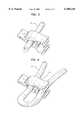
- FIGS. 2A and 2Billustrate side and perspective views, respectively, of an assembly connector constructed in accordance with the principles of the present invention.
- FIG. 3illustrates the connector of FIG. 1, assembled on an elongate member.
- FIG. 4illustrates the connector of FIG. 3, wherein the elongate member is secured thereby so as to form a loop.
- Fastening device 2is composed of first and second complimentary shaped injection molded plastic members 4 and 6.
- Member 4includes first and second partial-cylindrical portions 8 and 10 and member 6 includes complimentary shaped first and second partial-cylindrical portions 12 and 14.
- Portions 8, 12 and 10, 14are dimensioned so as to form a "snap" type of fit when these portions are urged towards each other so that the partial-cylindrical portions nest or engage one another.
- FIGS. 2A and 2Billustrate such an engagement or nesting of portions 8, 12. More specifically, when members 4 and 6 are urged towards each other by a user so that complimentary partial-cylindrical portions 8 and 12 engage each other, portions 8 and 12 form a hinge or pivot 15. Pivot 15 holds members 4 and 6 juxtaposed, while allowing a user of the device to squeeze tab-like portions 16 and 18 which extend from one end of each of members 4 and 6, to cause the opposite ends of members 4 and 6 to assume an "open" position.
- members 4 and 6can also be squeezed by the user of the device so as to cause complimentary partial-cylindrical portions 10 and 14 to engage each other in a snap-like fit in a manner similar to the engagement of portions 8 and 12, and thereby cause fastener 2 to assume a "closed” position.
- Raised edges 17are provided along at least a portion of the outer edges of partial-cylindrical portion 8 so as to prevent longitudinal movement, and disengagement of portions 8 and 12 after they have been engaged.
- partial-cylindrical portions 8, 12 and 10, 14Due to the shape of partial-cylindrical portions 8, 12 and 10, 14, their selective engagement provides additional functionality to the fastening device.
- FIG. 3shows assembly of the fastening device 2 upon an elongate member 20 that is secured within the hollow area inside pivot 15 formed by the engagement of complimentary partial-cylindrical portions 8 and 12.
- the height of the raised edges 17is dimensioned so as to facilitate a secure (non-slip) pressure engagement of the outside circumference of elongate element 20.
- Elongate member 20may comprise, for example, an electrical cable or other tubular element which requires connection to a patient, and at the same time needs attachment to an auxiliary object in order to provide strain relief to the patient.
- portions 10, 12can be used to engage a flexible sheet material (not shown) between the outer curved surface of portion 14 and the inner curved surface of partial-cylindrical portion 10. Due to the fact that these portions are engage for a snap fit, the flexible sheet material can be "pinched” or squeezed thereby, and accordingly securely fasten the elongate member to the sheet material and provide strain relief.
- the sheet materialmay comprise, for example, the gown of the patient, a pillowcase, a bed sheet, or other material having a somewhat fixed relation to the patient. Due to the flexible nature of the material used to injection mold members 4 and 6, a variety of different materials and thickness can be "grasped” by the selective engagement of portions 10, 12.
- the usercould form a loop in the elongate element by folding it back upon itself, and then clamp element 20 within the hollow formed between nested partial-cylindrical complimentary portions 10 and 14, as shown in FIG. 4.
- This arrangementallows for a variety of possibilities for positioning the elongate element in a somewhat stable and strain-relief position with respect to the patient by, for example, positioning the loop on the hook of an IV pole, or on a portion of the hospital bed.
- fastener 2is closed, so as to selectively engage a sheet material or elongate member within portions 10, 14, by squeezing the opposite ends of members 4 and 6 together.
- member 6includes a finger support area 26.
- the shape of device 2could be modified so as to accommodate an area like engagement area 15 in that portion of member 6 that resides between the outside walls of portions 8 and 10.
- a finger support areathat is similar to area 22 could be provided on the complimentary opposed side of member 4. All such changes, modifications, variations and other uses and applications which do not depart from the teachings herein are deemed to be covered by this patent, which is limited only by the claims which follow as interpreted in light of the foregoing description.
Landscapes
- Health & Medical Sciences (AREA)
- Engineering & Computer Science (AREA)
- General Engineering & Computer Science (AREA)
- Biomedical Technology (AREA)
- Anesthesiology (AREA)
- Heart & Thoracic Surgery (AREA)
- Hematology (AREA)
- Life Sciences & Earth Sciences (AREA)
- Animal Behavior & Ethology (AREA)
- General Health & Medical Sciences (AREA)
- Public Health (AREA)
- Veterinary Medicine (AREA)
- Vascular Medicine (AREA)
- Mechanical Engineering (AREA)
- Clamps And Clips (AREA)
- Invalid Beds And Related Equipment (AREA)
Abstract
Description
1. Field of the Invention
The invention relates to fastening devices, and more particularly to a snap type fastener for securing elongate or tubular elements.
2. Description of the Prior Art
The use of various devices for joining medical tubes and cables to a medical patient is well known in the medical arts. A representative one of many devices which facilitate such a joining is described in U.S. Pat. No. 4,308,642. The device comprises a generally rectangular pad having a "fuzzy fiber" (i.e., VELCRO®) gripping area for securing one or more elongate elements thereon, and an alligator-clip type of clamp at one end of the rectangular pad. During use, one or more elongate elements required to be joined with a patient are tightly secured onto the pad using the gripper area, and the assembly is then secured near the patient in order to support and relieve the strain of the elongate elements that are connected to the patient. The securing of the assembly is accomplished, for example, by engaging the bed sheet or gown of the patient between the jaws of the clip. Generally, the elongate elements comprise electrical cables and/or tubular members, such as required for monitoring physiological parameters of the patient, i.e., for monitoring the electrical heart activity (EKG) or blood pressure of the patient.
The use of a fuzzy fiber pad is generally undesirable from a cleanliness point of view due to the many small recesses that exist in the fibers, and a toothed metal clip is also undesirable due to the possibility of injury to the patient, rusting of the metal parts, and damaging of the medical tubes or cables.
It would be desirable to provide a device which can be easily operable using only one hand, to selectively secure elongate members that are joined with the patient to a variety of different types of supports (such as a bed sheet, hospital gown), in a non-obtrusive manner. It would be also be desirable for such a device to be easily manufactured use non-rusting parts, as well as parts that are easy to clean and are reusable a number of times without adversely affecting its operability.
A fastener comprising first and second separable members, for engaging an elongate element. Each member includes first and second complementary shaped partial-cylindrical portions formed on a facing side thereof. The first and second partial-cylindrical portions of the first member have outside dimensions that are complementarily dimensioned with respect to the inside dimensions of the first and second partial-cylindrical portions of the second member, so that the first and second partial-cylindrical portions of the first member selectively engage and nest within the first and second partial-cylindrical portions of the second member when the facing side of the first and second members are positioned towards each other. The elongate element is engaged between the first and second members of the fastener by an engagement area formed when one of the first and second partial-cylindrical portions are nested.
FIGS. 1A and 1B illustrate side and perspective views, respectively, of an unassembled connector constructed in accordance with the principles of the present invention.
FIGS. 2A and 2B illustrate side and perspective views, respectively, of an assembly connector constructed in accordance with the principles of the present invention.
FIG. 3 illustrates the connector of FIG. 1, assembled on an elongate member.
FIG. 4 illustrates the connector of FIG. 3, wherein the elongate member is secured thereby so as to form a loop.
Reference is now made to FIGS. 1A and B which show a side and perspective view, respectively, of an unassembled snap type of fastening device constructed in accordance with the principles of the present invention. Fasteningdevice 2 is composed of first and second complimentary shaped injection moldedplastic members 4 and 6. Member 4 includes first and second partial-cylindrical portions member 6 includes complimentary shaped first and second partial-cylindrical portions Portions
FIGS. 2A and 2B illustrate such an engagement or nesting ofportions members 4 and 6 are urged towards each other by a user so that complimentary partial-cylindrical portions portions pivot 15.Pivot 15 holdsmembers 4 and 6 juxtaposed, while allowing a user of the device to squeeze tab-like portions members 4 and 6, to cause the opposite ends ofmembers 4 and 6 to assume an "open" position. The opposite ends ofmembers 4 and 6 can also be squeezed by the user of the device so as to cause complimentary partial-cylindrical portions portions fastener 2 to assume a "closed" position. Raised edges 17 (shown more clearly in FIG. 1A) are provided along at least a portion of the outer edges of partial-cylindrical portion 8 so as to prevent longitudinal movement, and disengagement ofportions
Due to the shape of partial-cylindrical portions
More specifically, FIG. 3 shows assembly of thefastening device 2 upon anelongate member 20 that is secured within the hollow area insidepivot 15 formed by the engagement of complimentary partial-cylindrical portions edges 17 is dimensioned so as to facilitate a secure (non-slip) pressure engagement of the outside circumference ofelongate element 20. Elongatemember 20 may comprise, for example, an electrical cable or other tubular element which requires connection to a patient, and at the same time needs attachment to an auxiliary object in order to provide strain relief to the patient.
Furthermore, the fastening device of the present invention allows use of complimentary partial-cylindrical portions device 2 to an auxiliary object. For example,portions portion 14 and the inner curved surface of partial-cylindrical portion 10. Due to the fact that these portions are engage for a snap fit, the flexible sheet material can be "pinched" or squeezed thereby, and accordingly securely fasten the elongate member to the sheet material and provide strain relief. The sheet material may comprise, for example, the gown of the patient, a pillowcase, a bed sheet, or other material having a somewhat fixed relation to the patient. Due to the flexible nature of the material used toinjection mold members 4 and 6, a variety of different materials and thickness can be "grasped" by the selective engagement ofportions
In an alternative use of the present invention, the user could form a loop in the elongate element by folding it back upon itself, and thenclamp element 20 within the hollow formed between nested partial-cylindricalcomplimentary portions
As previously noted, the selective engaging end offastening device 2 is opened by the user squeezing together tab-like portions fastener 2 is closed, so as to selectively engage a sheet material or elongate member withinportions members 4 and 6 together. For this purpose, as illustrated in FIG. 4,member 6 includes a finger support area 26.
Thus, there has been shown and described a novel apparatus for a snap fastening device. Many changes, modifications, variations and other uses and applications of the subject invention will, however, become apparent to those skilled in the art after considering this specification and its accompanying drawings, which disclose a preferred embodiment thereof. For example, although all of the illustrated partial-cylindrical portions are shown as wall-type (tubular) structures,device 2 would still function if partial-cylindrical portions portions portions device 2 could be modified so as to accommodate an area likeengagement area 15 in that portion ofmember 6 that resides between the outside walls ofportions area 22 could be provided on the complimentary opposed side of member 4. All such changes, modifications, variations and other uses and applications which do not depart from the teachings herein are deemed to be covered by this patent, which is limited only by the claims which follow as interpreted in light of the foregoing description.
Claims (10)
1. A fastener for engaging an elongate element, comprising:
first and second separable members, each member including first and second complementary shaped partial-cylindrical portions formed on a facing side thereof,
wherein the first and second partial-cylindrical portions of the first member have outside dimensions that are complementarily dimensioned with respect to inside dimensions of the first and second partial-cylindrical portions of the second member, so that the first and second partial-cylindrical portions of the first member selectively engage and nest within the first and second partial-cylindrical portions of the second member when the facing side of the first and second members are positioned towards each other, thereby forming a rotatable pivot point for said first and second members when the first partial-cylindrical portions of the first and second members are nested,
and wherein the elongate element is engaged between the first and second members of the fastener by an engagement area formed when one of the first and second partial-cylindrical portions are nested.
2. The fastener of claim 1, wherein the first partial-cylindrical portions have a tubular shape so as to form a hollow as said engagement area in the center of the rotatable pivot point.
3. The fastener of claim 2, wherein the first and second members are formed of a flexible plastic material so as to facilitate a snap engagement the first partial-cylindrical portions of the first and second members when they nest.
4. The fastener of claim 1, wherein the second partial-cylindrical portions have a tubular shape so as to form a hollow engagement area therein when they are nested.
5. The fastener of claim 4, wherein the hollow engagement area formed by the nesting of the second partial-cylindrical portions is shaped so as to also engage the elongate element.
6. The fastener of claim 4, wherein the first and second members are formed of a flexible plastic material so as to facilitate a snap engagement the second partial-cylindrical portions of the first and second members when they nest.
7. A fastener for engaging an elongate element, comprising:
first and second separable members, each member including first and second complementary shaped partial-cylindrical wall portions formed on a facing side thereof,
wherein the first and second partial-cylindrical wall portions of the first member have outside dimensions that are complementarily dimensioned with respect to inside dimensions of the first and second partial-cylindrical wall portions of the second member, so that the first and second partial-cylindrical portions of the first member selectively engage with a snap fit so as to nest within the first and second partial-cylindrical portions of the second member when the facing side of the first and second members are positioned towards each other, thereby forming a rotatable pivot point for said first and second members, and
wherein at least one hollow centered at said rotatable pivot point is created by the nesting of one of the first and second partial-cylindrical portions, said hollow being dimensioned for engaging the elongate element.
8. The fastener of claim 7, said hollow is created in the center of the rotatable pivot point.
9. The fastener of claim 7, wherein the first and second members are formed of a flexible plastic material so as to facilitate a snap engagement of the first partial-cylindrical wall portions of the first and second members when they nest.
10. The fastener of claim 7, wherein first and second hollows are formed by the nesting of the first and second partial-cylindrical wall portions, respectively, both hollows being shaped so as to engage the elongate element.
Priority Applications (2)
| Application Number | Priority Date | Filing Date | Title |
|---|---|---|---|
| US09/212,887US6105218A (en) | 1998-12-16 | 1998-12-16 | Snap-type fastening device |
| DE19959965ADE19959965B4 (en) | 1998-12-16 | 1999-12-13 | Snap-type fastening device |
Applications Claiming Priority (1)
| Application Number | Priority Date | Filing Date | Title |
|---|---|---|---|
| US09/212,887US6105218A (en) | 1998-12-16 | 1998-12-16 | Snap-type fastening device |
Publications (1)
| Publication Number | Publication Date |
|---|---|
| US6105218Atrue US6105218A (en) | 2000-08-22 |
Family
ID=22792797
Family Applications (1)
| Application Number | Title | Priority Date | Filing Date |
|---|---|---|---|
| US09/212,887Expired - LifetimeUS6105218A (en) | 1998-12-16 | 1998-12-16 | Snap-type fastening device |
Country Status (2)
| Country | Link |
|---|---|
| US (1) | US6105218A (en) |
| DE (1) | DE19959965B4 (en) |
Cited By (87)
| Publication number | Priority date | Publication date | Assignee | Title |
|---|---|---|---|---|
| US6523231B1 (en)* | 1998-07-02 | 2003-02-25 | Jerry E. Lassiter | Power cord clip |
| US6526635B2 (en)* | 2000-08-10 | 2003-03-04 | Hosiden Corporation | Cord clip |
| US6618910B1 (en)* | 2000-10-11 | 2003-09-16 | Illinois Tool Works Inc. | Cord clamp |
| US6712320B2 (en)* | 2001-07-17 | 2004-03-30 | Alexander F. Rivera | Single-handed cord/cable management device |
| US20040105723A1 (en)* | 2002-11-29 | 2004-06-03 | Nifco Inc. | Attaching device for fuel tank band |
| US20050072884A1 (en)* | 2001-07-17 | 2005-04-07 | Rivera Alexander F. | Single-handed cord/cable management device |
| US20050091801A1 (en)* | 2003-10-31 | 2005-05-05 | Feschuk J. P. | Slip grip device |
| US6969832B1 (en) | 2003-05-19 | 2005-11-29 | Daughtry Sr Timothy Douglas | Radiant floor heating and cooling system clip |
| EP1604581A1 (en)* | 2004-06-11 | 2005-12-14 | Philip Troy Christy | Lace tightening article |
| US20060100581A1 (en)* | 2004-08-13 | 2006-05-11 | Mogensen Lasse W | Reservoir for front end loaded infusion device |
| US20060116245A1 (en)* | 2004-11-29 | 2006-06-01 | Gemma Palmenco-Geller | Limb weight device |
| US7070580B2 (en) | 2003-04-01 | 2006-07-04 | Unomedical A/S | Infusion device and an adhesive sheet material and a release liner |
| USD526409S1 (en) | 1998-07-14 | 2006-08-08 | Unomedical A/S | Medical puncturing device |
| US7086346B1 (en)* | 2004-09-16 | 2006-08-08 | Van Horn Steven M | Apparatus as a flag or banner pole clip |
| US7115112B2 (en) | 2002-09-02 | 2006-10-03 | Unomedical A/S | Device for subcutaneous administration of a medicament to a patient and tubing for same |
| US7147623B2 (en) | 2002-02-12 | 2006-12-12 | Unomedical A/S | Infusion device with needle shield |
| US20070018057A1 (en)* | 2005-07-20 | 2007-01-25 | Zdravko Kovac | Hinged clip having a retainer |
| US7258680B2 (en)* | 2002-09-02 | 2007-08-21 | Unomedical A/S | Device for subcutaneous administration of a medicament to a patient |
| US20070215759A1 (en)* | 2006-03-17 | 2007-09-20 | Heegaard Roger W | Device for organizing slack in medical tubing |
| US20070239121A1 (en)* | 2006-04-11 | 2007-10-11 | Stephen Tully | Adjustable drain loop for urine collection system |
| USD554253S1 (en) | 2003-10-15 | 2007-10-30 | Unomedical A/S | Medical infusion device |
| US20080000006A1 (en)* | 2006-06-09 | 2008-01-03 | Texas Children's Hospital | Hospital patient gown |
| US20080092349A1 (en)* | 2006-09-07 | 2008-04-24 | Carol Cofer | Clip having a sheath for holding tubing or cords |
| US20080118304A1 (en)* | 2004-09-10 | 2008-05-22 | Carraher John M | Rebar Junction Clip And Method For Securing Rebar Thereby |
| US7407493B2 (en) | 2001-12-28 | 2008-08-05 | Unomedical A/S | Container for disposable needle or cannula |
| US20080196214A1 (en)* | 2005-06-16 | 2008-08-21 | Peter Eklund | Rope Clip |
| USD576267S1 (en) | 2003-10-15 | 2008-09-02 | Unomedical A/S | Medical infusion device |
| US20080247818A1 (en)* | 2004-03-10 | 2008-10-09 | Marc Oesch | Device For Mutual Positioning of Longitudinal Building Components |
| USD579541S1 (en) | 2003-10-15 | 2008-10-28 | Unomedical A/S | Medical insertion device |
| US20080277853A1 (en)* | 2007-05-09 | 2008-11-13 | Microline Pentax Inc. | Clip for coupling a surgical tool and scope |
| US7481794B2 (en) | 2003-02-12 | 2009-01-27 | Unomedical A/S | Cover |
| US20090127217A1 (en)* | 2006-02-10 | 2009-05-21 | Paul Hettich Gmbh & Co. Kg | Guide Rail Comprising a Rapid Fixing Device |
| US20090198171A1 (en)* | 2006-06-10 | 2009-08-06 | Wolfgang Kleinekofort | Device for use in an arrangement for monitoring an access to a patient, and method for monitoring a patient access, in a particular vascular access in extracorporeal blood treatment |
| JP2009529388A (en)* | 2006-03-11 | 2009-08-20 | フレゼニウス メディカル ケア ドイチュランド ゲゼルシャフト ミット ベシュレンクテル ハフトング | Device and method for monitoring access to a patient, particularly access to a blood vessel during extracorporeal blood treatment |
| US7594909B2 (en) | 2002-09-02 | 2009-09-29 | Unomedical, A/S | Apparatus and method for adjustment of the length of an infusion tubing |
| US7621395B2 (en) | 2005-06-28 | 2009-11-24 | Unomedical A/S | Packing for infusion set and method of applying an infusion set |
| US7648494B2 (en) | 2004-03-26 | 2010-01-19 | Unomedical A/S | Infusion set and injector device for infusion set |
| US7654484B2 (en) | 2002-09-02 | 2010-02-02 | Unomedical A/S | Apparatus for and a method of adjusting the length of an infusion tube |
| US20100122834A1 (en)* | 2008-11-20 | 2010-05-20 | Shih-Hsing Chang | Wire organization structure |
| US7784157B1 (en) | 2007-08-03 | 2010-08-31 | MTS 911 Wear Inc. | Apparatus to retain a coil wire from a microphone to prevent the microphone from falling away from a person |
| US7802824B2 (en) | 2002-11-26 | 2010-09-28 | Unomedical A/S | Connecting piece for a tubing |
| US7867200B2 (en) | 2004-12-10 | 2011-01-11 | Unomedical A/S | Inserter |
| USD632030S1 (en)* | 2008-02-28 | 2011-02-01 | Pink Chilli Pty. Ltd. | Clamp for animal leads, reins and tethers |
| US7985199B2 (en) | 2005-03-17 | 2011-07-26 | Unomedical A/S | Gateway system |
| US8012126B2 (en) | 2006-10-31 | 2011-09-06 | Unomedical A/S | Infusion set |
| US8062250B2 (en) | 2004-08-10 | 2011-11-22 | Unomedical A/S | Cannula device |
| US20110315830A1 (en)* | 2010-06-23 | 2011-12-29 | Hitachi Cable, Ltd. | Cable fixing member and cable fixing structure |
| USD655807S1 (en) | 2005-12-09 | 2012-03-13 | Unomedical A/S | Medical device |
| US8152771B2 (en) | 2001-09-27 | 2012-04-10 | Unomedical A/S | Injector device for placing a subcutaneous infusion set |
| US8246588B2 (en) | 2007-07-18 | 2012-08-21 | Unomedical A/S | Insertion device with pivoting action |
| US8303549B2 (en) | 2005-12-23 | 2012-11-06 | Unomedical A/S | Injection device |
| US20130035627A1 (en)* | 2011-08-04 | 2013-02-07 | Fresenius Medical Care Deutschland Gmbh | Device and method for fixing a segment of tubing, for an arrangement for monitoring an access to a patient |
| US8430850B2 (en) | 2007-07-03 | 2013-04-30 | Unomedical A/S | Inserter having bistable equilibrium states |
| US8439838B2 (en) | 2006-06-07 | 2013-05-14 | Unomedical A/S | Inserter for transcutaneous sensor |
| US8486003B2 (en) | 2007-07-10 | 2013-07-16 | Unomedical A/S | Inserter having two springs |
| US20130188357A1 (en)* | 2008-12-12 | 2013-07-25 | The Sloan Company, Inc. Dba Sloanled | Channel letter lighting system using high output white light emitting diodes |
| US8562567B2 (en) | 2009-07-30 | 2013-10-22 | Unomedical A/S | Inserter device with horizontal moving part |
| US20140115836A1 (en)* | 2012-10-26 | 2014-05-01 | Hsun Chang | Slide On Zipper Assembly |
| US20140117171A1 (en)* | 2012-10-31 | 2014-05-01 | Roland Corporation | Cable holder |
| US20140200524A1 (en)* | 2013-01-11 | 2014-07-17 | C.R.Bard, Inc. | Curved Catheter and Methods for Making Same |
| US8790311B2 (en) | 2006-06-09 | 2014-07-29 | Unomedical A/S | Mounting pad |
| US8945057B2 (en) | 2006-08-02 | 2015-02-03 | Unomedical A/S | Cannula and delivery device |
| US9186480B2 (en) | 2007-06-20 | 2015-11-17 | Unomedical A/S | Apparatus for making a catheter |
| US20150345666A1 (en)* | 2011-07-14 | 2015-12-03 | Subsea 7 Limited | Pipelaying |
| US9211379B2 (en) | 2006-02-28 | 2015-12-15 | Unomedical A/S | Inserter for infusion part and infusion part provided with needle protector |
| US9254373B2 (en) | 2008-12-22 | 2016-02-09 | Unomedical A/S | Medical device comprising adhesive pad |
| US9415159B2 (en) | 2010-03-30 | 2016-08-16 | Unomedical A/S | Medical device |
| US9440051B2 (en) | 2011-10-27 | 2016-09-13 | Unomedical A/S | Inserter for a multiplicity of subcutaneous parts |
| US20160346461A1 (en)* | 2015-05-22 | 2016-12-01 | Eric Mcleod | Intravenous medicament line organizer |
| US9533092B2 (en) | 2009-08-07 | 2017-01-03 | Unomedical A/S | Base part for a medication delivery device |
| US9566384B2 (en) | 2008-02-20 | 2017-02-14 | Unomedical A/S | Insertion device with horizontally moving part |
| US9724127B2 (en) | 2010-09-27 | 2017-08-08 | Unomedical A/S | Insertion system and insertion kit |
| US20170290989A1 (en)* | 2016-04-12 | 2017-10-12 | Jonathan Mancini | Clip systems |
| US20180064264A1 (en)* | 2013-07-16 | 2018-03-08 | Fasteners For Retail, Inc. | Lock for securing front rail to wire shelving |
| US10003180B1 (en)* | 2015-11-30 | 2018-06-19 | Chatsworth Products, Inc. | Cable pathway divider and method for installing same |
| US10237994B2 (en) | 2010-09-10 | 2019-03-19 | Chatsworth Products, Inc. | Vertical mounting rail with cable management features |
| US10337550B2 (en) | 2015-12-14 | 2019-07-02 | Chatsworth Products, Inc. | Cage nut fastener and methods for tool-less installation of same |
| US10374360B2 (en) | 2012-01-27 | 2019-08-06 | Chatsworth Products, Inc. | Cable retention system for power distribution unit |
| US10369277B2 (en) | 2005-09-12 | 2019-08-06 | Unomedical A/S | Invisible needle |
| CN110454849A (en)* | 2019-07-31 | 2019-11-15 | 山东尚治管业有限公司 | A modular structure for convenient laying of floor heating pipelines |
| US10898643B2 (en) | 2008-02-13 | 2021-01-26 | Unomedical A/S | Sealing between a cannula part and a fluid path |
| US11020526B2 (en) | 2010-10-04 | 2021-06-01 | Unomedical A/S | Sprinkler cannula |
| US20210245684A1 (en)* | 2020-02-06 | 2021-08-12 | Rosemount Aerospace Inc. | Adapter clip |
| US11110261B2 (en) | 2011-10-19 | 2021-09-07 | Unomedical A/S | Infusion tube system and method for manufacture |
| US11197689B2 (en) | 2011-10-05 | 2021-12-14 | Unomedical A/S | Inserter for simultaneous insertion of multiple transcutaneous parts |
| USD942256S1 (en) | 2020-08-17 | 2022-02-01 | Innovative Dental Technologies, Inc | Clip |
| US11909154B1 (en) | 2021-03-08 | 2024-02-20 | Chatsworth Products, Inc. | Endcap for establishing electrical bonding connection |
Families Citing this family (3)
| Publication number | Priority date | Publication date | Assignee | Title |
|---|---|---|---|---|
| DE20213004U1 (en) | 2002-08-24 | 2002-11-07 | JOSTRA AG, 72145 Hirrlingen | Device for holding hose lines |
| DE102008026916A1 (en) | 2008-06-05 | 2009-12-17 | Fresenius Medical Care Deutschland Gmbh | Organizer for releasably receiving components of blood tubing sets and methods of making and preparing same |
| DE202012002894U1 (en)* | 2012-03-22 | 2013-06-25 | Stiebel Eltron Gmbh & Co. Kg | Heat pump with a holder for pressure sensors |
Citations (13)
| Publication number | Priority date | Publication date | Assignee | Title |
|---|---|---|---|---|
| US3809371A (en)* | 1973-06-29 | 1974-05-07 | Master Fence Fittings Inc | Tension band |
| US4118838A (en)* | 1976-04-14 | 1978-10-10 | Hilti Aktiengesellschaft | Pipe clamp |
| US4308642A (en)* | 1978-10-02 | 1982-01-05 | Arnold Heyman | Hospital utility device |
| US4771516A (en)* | 1984-05-11 | 1988-09-20 | Istvan Foth | Device for the inter-connection of ropes |
| US4971271A (en)* | 1989-05-05 | 1990-11-20 | Sularz Frank D | Article organizer and holder assembly |
| EP0572684A1 (en)* | 1992-05-15 | 1993-12-08 | Hewlett-Packard GmbH | Medical sensor |
| US5459903A (en)* | 1993-12-16 | 1995-10-24 | Treacy; Brian M. | Method and apparatus for supporting an item proximate to a person's mouth |
| US5494245A (en)* | 1994-05-04 | 1996-02-27 | Yazaki Corporation | Wiring harness retainer clip |
| US5535969A (en)* | 1994-03-14 | 1996-07-16 | Illinois Tool Works Inc. | Fold over scissors clip |
| US5572776A (en)* | 1994-12-12 | 1996-11-12 | Delco Electronics Corporation | Fastener employing a Bi-stable mechanism |
| US5703330A (en)* | 1992-11-16 | 1997-12-30 | Bundy Corporation | Wire harness conduit and tube bundle |
| US5820048A (en)* | 1996-04-09 | 1998-10-13 | Illinois Tool Works Inc. | Side latching hinge mechanism |
| US5937488A (en)* | 1998-07-13 | 1999-08-17 | Tyton Hellerman Corporation | Brakeline to axle clamp |
Family Cites Families (4)
| Publication number | Priority date | Publication date | Assignee | Title |
|---|---|---|---|---|
| US4431152A (en)* | 1981-12-10 | 1984-02-14 | Square D Company | Adjustable cable restraint assembly |
| DE3913360C1 (en)* | 1989-04-22 | 1990-09-13 | Fa. A. Raymond, 7850 Loerrach, De | |
| DE9407618U1 (en)* | 1994-05-06 | 1995-09-07 | Emhart Inc., Newark, Del. | Fastening device for lines |
| DE29817834U1 (en)* | 1998-10-06 | 1998-12-24 | TRW Automotive Safety Systems GmbH, 63743 Aschaffenburg | Device for bundling cables |
- 1998
- 1998-12-16USUS09/212,887patent/US6105218A/ennot_activeExpired - Lifetime
- 1999
- 1999-12-13DEDE19959965Apatent/DE19959965B4/ennot_activeExpired - Lifetime
Patent Citations (13)
| Publication number | Priority date | Publication date | Assignee | Title |
|---|---|---|---|---|
| US3809371A (en)* | 1973-06-29 | 1974-05-07 | Master Fence Fittings Inc | Tension band |
| US4118838A (en)* | 1976-04-14 | 1978-10-10 | Hilti Aktiengesellschaft | Pipe clamp |
| US4308642A (en)* | 1978-10-02 | 1982-01-05 | Arnold Heyman | Hospital utility device |
| US4771516A (en)* | 1984-05-11 | 1988-09-20 | Istvan Foth | Device for the inter-connection of ropes |
| US4971271A (en)* | 1989-05-05 | 1990-11-20 | Sularz Frank D | Article organizer and holder assembly |
| EP0572684A1 (en)* | 1992-05-15 | 1993-12-08 | Hewlett-Packard GmbH | Medical sensor |
| US5703330A (en)* | 1992-11-16 | 1997-12-30 | Bundy Corporation | Wire harness conduit and tube bundle |
| US5459903A (en)* | 1993-12-16 | 1995-10-24 | Treacy; Brian M. | Method and apparatus for supporting an item proximate to a person's mouth |
| US5535969A (en)* | 1994-03-14 | 1996-07-16 | Illinois Tool Works Inc. | Fold over scissors clip |
| US5494245A (en)* | 1994-05-04 | 1996-02-27 | Yazaki Corporation | Wiring harness retainer clip |
| US5572776A (en)* | 1994-12-12 | 1996-11-12 | Delco Electronics Corporation | Fastener employing a Bi-stable mechanism |
| US5820048A (en)* | 1996-04-09 | 1998-10-13 | Illinois Tool Works Inc. | Side latching hinge mechanism |
| US5937488A (en)* | 1998-07-13 | 1999-08-17 | Tyton Hellerman Corporation | Brakeline to axle clamp |
Cited By (136)
| Publication number | Priority date | Publication date | Assignee | Title |
|---|---|---|---|---|
| US6523231B1 (en)* | 1998-07-02 | 2003-02-25 | Jerry E. Lassiter | Power cord clip |
| USD526409S1 (en) | 1998-07-14 | 2006-08-08 | Unomedical A/S | Medical puncturing device |
| US6526635B2 (en)* | 2000-08-10 | 2003-03-04 | Hosiden Corporation | Cord clip |
| US6618910B1 (en)* | 2000-10-11 | 2003-09-16 | Illinois Tool Works Inc. | Cord clamp |
| US7077363B2 (en)* | 2001-07-17 | 2006-07-18 | Alexander F. Rivera | Single-handed cord/cable management device |
| US6712320B2 (en)* | 2001-07-17 | 2004-03-30 | Alexander F. Rivera | Single-handed cord/cable management device |
| US20050072884A1 (en)* | 2001-07-17 | 2005-04-07 | Rivera Alexander F. | Single-handed cord/cable management device |
| US8172805B2 (en) | 2001-09-27 | 2012-05-08 | Unomedical A/S | Injector device for placing a subcutaneous infusion set |
| US8152771B2 (en) | 2001-09-27 | 2012-04-10 | Unomedical A/S | Injector device for placing a subcutaneous infusion set |
| US8162892B2 (en) | 2001-09-27 | 2012-04-24 | Unomedical A/S | Injector device for placing a subcutaneous infusion set |
| US7407493B2 (en) | 2001-12-28 | 2008-08-05 | Unomedical A/S | Container for disposable needle or cannula |
| US7147623B2 (en) | 2002-02-12 | 2006-12-12 | Unomedical A/S | Infusion device with needle shield |
| US7258680B2 (en)* | 2002-09-02 | 2007-08-21 | Unomedical A/S | Device for subcutaneous administration of a medicament to a patient |
| US7654484B2 (en) | 2002-09-02 | 2010-02-02 | Unomedical A/S | Apparatus for and a method of adjusting the length of an infusion tube |
| US7594909B2 (en) | 2002-09-02 | 2009-09-29 | Unomedical, A/S | Apparatus and method for adjustment of the length of an infusion tubing |
| US7115112B2 (en) | 2002-09-02 | 2006-10-03 | Unomedical A/S | Device for subcutaneous administration of a medicament to a patient and tubing for same |
| US7802824B2 (en) | 2002-11-26 | 2010-09-28 | Unomedical A/S | Connecting piece for a tubing |
| US7037025B2 (en)* | 2002-11-29 | 2006-05-02 | Nifco Inc. | Attaching device for fuel tank band |
| US20040105723A1 (en)* | 2002-11-29 | 2004-06-03 | Nifco Inc. | Attaching device for fuel tank band |
| US7481794B2 (en) | 2003-02-12 | 2009-01-27 | Unomedical A/S | Cover |
| US7070580B2 (en) | 2003-04-01 | 2006-07-04 | Unomedical A/S | Infusion device and an adhesive sheet material and a release liner |
| US6969832B1 (en) | 2003-05-19 | 2005-11-29 | Daughtry Sr Timothy Douglas | Radiant floor heating and cooling system clip |
| USD576267S1 (en) | 2003-10-15 | 2008-09-02 | Unomedical A/S | Medical infusion device |
| USD554253S1 (en) | 2003-10-15 | 2007-10-30 | Unomedical A/S | Medical infusion device |
| USD579541S1 (en) | 2003-10-15 | 2008-10-28 | Unomedical A/S | Medical insertion device |
| US7237307B2 (en) | 2003-10-31 | 2007-07-03 | J Peter Feschuk | Slip grip device |
| US20050091801A1 (en)* | 2003-10-31 | 2005-05-05 | Feschuk J. P. | Slip grip device |
| US10746214B2 (en) | 2004-03-10 | 2020-08-18 | DePuy Synthes Products, Inc. | Device for mutual positioning of longitudinal building components |
| US9089368B2 (en)* | 2004-03-10 | 2015-07-28 | DePuy Synthes Products, Inc. | Device for mutual positioning of longitudinal building components |
| US20080247818A1 (en)* | 2004-03-10 | 2008-10-09 | Marc Oesch | Device For Mutual Positioning of Longitudinal Building Components |
| US8221355B2 (en) | 2004-03-26 | 2012-07-17 | Unomedical A/S | Injection device for infusion set |
| US8287516B2 (en) | 2004-03-26 | 2012-10-16 | Unomedical A/S | Infusion set |
| US7648494B2 (en) | 2004-03-26 | 2010-01-19 | Unomedical A/S | Infusion set and injector device for infusion set |
| EP1604581A1 (en)* | 2004-06-11 | 2005-12-14 | Philip Troy Christy | Lace tightening article |
| US8062250B2 (en) | 2004-08-10 | 2011-11-22 | Unomedical A/S | Cannula device |
| US20060100581A1 (en)* | 2004-08-13 | 2006-05-11 | Mogensen Lasse W | Reservoir for front end loaded infusion device |
| US20080118304A1 (en)* | 2004-09-10 | 2008-05-22 | Carraher John M | Rebar Junction Clip And Method For Securing Rebar Thereby |
| US7086346B1 (en)* | 2004-09-16 | 2006-08-08 | Van Horn Steven M | Apparatus as a flag or banner pole clip |
| US20060116245A1 (en)* | 2004-11-29 | 2006-06-01 | Gemma Palmenco-Geller | Limb weight device |
| US7867199B2 (en) | 2004-12-10 | 2011-01-11 | Unomedical A/S | Inserter |
| US7867200B2 (en) | 2004-12-10 | 2011-01-11 | Unomedical A/S | Inserter |
| US7985199B2 (en) | 2005-03-17 | 2011-07-26 | Unomedical A/S | Gateway system |
| US20080196214A1 (en)* | 2005-06-16 | 2008-08-21 | Peter Eklund | Rope Clip |
| US7621395B2 (en) | 2005-06-28 | 2009-11-24 | Unomedical A/S | Packing for infusion set and method of applying an infusion set |
| US7387282B2 (en) | 2005-07-20 | 2008-06-17 | Newfrey Llc | Hinged clip having a retainer |
| US20070018057A1 (en)* | 2005-07-20 | 2007-01-25 | Zdravko Kovac | Hinged clip having a retainer |
| US10369277B2 (en) | 2005-09-12 | 2019-08-06 | Unomedical A/S | Invisible needle |
| USD655807S1 (en) | 2005-12-09 | 2012-03-13 | Unomedical A/S | Medical device |
| USD682415S1 (en) | 2005-12-09 | 2013-05-14 | Unomedical A/S | Medical device |
| US8303549B2 (en) | 2005-12-23 | 2012-11-06 | Unomedical A/S | Injection device |
| US9278173B2 (en) | 2005-12-23 | 2016-03-08 | Unomedical A/S | Device for administration |
| US8573720B2 (en)* | 2006-02-10 | 2013-11-05 | Paul Hettich Gmbh & Co. Kg | Guide rail comprising a rapid fixing device |
| US20090127217A1 (en)* | 2006-02-10 | 2009-05-21 | Paul Hettich Gmbh & Co. Kg | Guide Rail Comprising a Rapid Fixing Device |
| US9211379B2 (en) | 2006-02-28 | 2015-12-15 | Unomedical A/S | Inserter for infusion part and infusion part provided with needle protector |
| US8177736B2 (en)* | 2006-03-11 | 2012-05-15 | Fresenius Medical Care Deutschland Gmbh | Device and method for monitoring access to a patient, in particular access to vessels during extracorporeal blood treatment |
| JP2009529388A (en)* | 2006-03-11 | 2009-08-20 | フレゼニウス メディカル ケア ドイチュランド ゲゼルシャフト ミット ベシュレンクテル ハフトング | Device and method for monitoring access to a patient, particularly access to a blood vessel during extracorporeal blood treatment |
| US20090306574A1 (en)* | 2006-03-11 | 2009-12-10 | Pascal Kopperschmidt | Device and method for monitoring access to a patient, in particular access to vessels during extracorporeal blood treatment |
| CN101400389B (en)* | 2006-03-11 | 2012-08-29 | 弗雷泽纽斯医疗保健德国有限公司 | Device and method for monitoring access to a patient, in particular access to vessels during extracorporeal blood treatment |
| US20070215759A1 (en)* | 2006-03-17 | 2007-09-20 | Heegaard Roger W | Device for organizing slack in medical tubing |
| US8333745B2 (en) | 2006-04-11 | 2012-12-18 | Covidien Lp | Adjustable drain loop for urine collection system |
| US20070239121A1 (en)* | 2006-04-11 | 2007-10-11 | Stephen Tully | Adjustable drain loop for urine collection system |
| US20090082742A1 (en)* | 2006-04-11 | 2009-03-26 | Tyco Healthcare Group Lp | Adjustable drain loop for urine collection system |
| US8439838B2 (en) | 2006-06-07 | 2013-05-14 | Unomedical A/S | Inserter for transcutaneous sensor |
| US20080000006A1 (en)* | 2006-06-09 | 2008-01-03 | Texas Children's Hospital | Hospital patient gown |
| US8790311B2 (en) | 2006-06-09 | 2014-07-29 | Unomedical A/S | Mounting pad |
| CN101466420B (en)* | 2006-06-10 | 2012-10-31 | 弗雷泽纽斯医疗保健德国有限公司 | Device for use in a system for monitoring patient access, and method for monitoring patient access, particularly vascular access in extracorporeal blood treatment |
| US20090198171A1 (en)* | 2006-06-10 | 2009-08-06 | Wolfgang Kleinekofort | Device for use in an arrangement for monitoring an access to a patient, and method for monitoring a patient access, in a particular vascular access in extracorporeal blood treatment |
| US8945057B2 (en) | 2006-08-02 | 2015-02-03 | Unomedical A/S | Cannula and delivery device |
| US7559125B2 (en) | 2006-09-07 | 2009-07-14 | Carol Cofer | Clip having a sheath for holding tubing or cords |
| US20080092349A1 (en)* | 2006-09-07 | 2008-04-24 | Carol Cofer | Clip having a sheath for holding tubing or cords |
| US8012126B2 (en) | 2006-10-31 | 2011-09-06 | Unomedical A/S | Infusion set |
| US20080277853A1 (en)* | 2007-05-09 | 2008-11-13 | Microline Pentax Inc. | Clip for coupling a surgical tool and scope |
| US9186480B2 (en) | 2007-06-20 | 2015-11-17 | Unomedical A/S | Apparatus for making a catheter |
| US9320869B2 (en) | 2007-06-20 | 2016-04-26 | Unomedical A/S | Apparatus for making a catheter |
| US8430850B2 (en) | 2007-07-03 | 2013-04-30 | Unomedical A/S | Inserter having bistable equilibrium states |
| US8486003B2 (en) | 2007-07-10 | 2013-07-16 | Unomedical A/S | Inserter having two springs |
| US8246588B2 (en) | 2007-07-18 | 2012-08-21 | Unomedical A/S | Insertion device with pivoting action |
| US7784157B1 (en) | 2007-08-03 | 2010-08-31 | MTS 911 Wear Inc. | Apparatus to retain a coil wire from a microphone to prevent the microphone from falling away from a person |
| US10898643B2 (en) | 2008-02-13 | 2021-01-26 | Unomedical A/S | Sealing between a cannula part and a fluid path |
| US9566384B2 (en) | 2008-02-20 | 2017-02-14 | Unomedical A/S | Insertion device with horizontally moving part |
| US10376637B2 (en) | 2008-02-20 | 2019-08-13 | Unomedical A/S | Insertion device with horizontally moving part |
| USD632030S1 (en)* | 2008-02-28 | 2011-02-01 | Pink Chilli Pty. Ltd. | Clamp for animal leads, reins and tethers |
| US20100122834A1 (en)* | 2008-11-20 | 2010-05-20 | Shih-Hsing Chang | Wire organization structure |
| US20130188357A1 (en)* | 2008-12-12 | 2013-07-25 | The Sloan Company, Inc. Dba Sloanled | Channel letter lighting system using high output white light emitting diodes |
| US9254373B2 (en) | 2008-12-22 | 2016-02-09 | Unomedical A/S | Medical device comprising adhesive pad |
| US8562567B2 (en) | 2009-07-30 | 2013-10-22 | Unomedical A/S | Inserter device with horizontal moving part |
| US9533092B2 (en) | 2009-08-07 | 2017-01-03 | Unomedical A/S | Base part for a medication delivery device |
| US11786653B2 (en) | 2010-03-30 | 2023-10-17 | Unomedical A/S | Insertion device |
| US9415159B2 (en) | 2010-03-30 | 2016-08-16 | Unomedical A/S | Medical device |
| US9112341B2 (en)* | 2010-06-23 | 2015-08-18 | Hitachi Metals, Ltd. | Cable fixing member and cable fixing structure |
| US20110315830A1 (en)* | 2010-06-23 | 2011-12-29 | Hitachi Cable, Ltd. | Cable fixing member and cable fixing structure |
| US11039543B2 (en) | 2010-09-10 | 2021-06-15 | Chatsworth Products, Inc. | Vertical mounting rail with cable management features |
| US10588227B2 (en) | 2010-09-10 | 2020-03-10 | Chatsworth Products, Inc. | Vertical mounting rail with cable management features |
| US10237994B2 (en) | 2010-09-10 | 2019-03-19 | Chatsworth Products, Inc. | Vertical mounting rail with cable management features |
| US9724127B2 (en) | 2010-09-27 | 2017-08-08 | Unomedical A/S | Insertion system and insertion kit |
| US11020526B2 (en) | 2010-10-04 | 2021-06-01 | Unomedical A/S | Sprinkler cannula |
| US20150345666A1 (en)* | 2011-07-14 | 2015-12-03 | Subsea 7 Limited | Pipelaying |
| US9719613B2 (en)* | 2011-07-14 | 2017-08-01 | Subsea 7 Limited | Pipelaying |
| CN103857422B (en)* | 2011-08-04 | 2016-01-20 | 弗雷泽纽斯医疗保健德国有限公司 | The apparatus and method to the conduit section of the device of the path of patient are monitored for being fixed for |
| US20130035627A1 (en)* | 2011-08-04 | 2013-02-07 | Fresenius Medical Care Deutschland Gmbh | Device and method for fixing a segment of tubing, for an arrangement for monitoring an access to a patient |
| US9561319B2 (en)* | 2011-08-04 | 2017-02-07 | Fresenius Medical Care Deutschland Gmbh | Device and method for fixing a segment of tubing, for an arrangement for monitoring an access to a patient |
| CN103857422A (en)* | 2011-08-04 | 2014-06-11 | 弗雷泽纽斯医疗保健德国有限公司 | Device and method for fixing a hose segment for a device for monitoring a patient access |
| US11197689B2 (en) | 2011-10-05 | 2021-12-14 | Unomedical A/S | Inserter for simultaneous insertion of multiple transcutaneous parts |
| US12178984B2 (en) | 2011-10-19 | 2024-12-31 | Unomedical A/S | Infusion tube system and method for manufacture |
| US11684767B2 (en) | 2011-10-19 | 2023-06-27 | Unomedical A/S | Infusion tube system and method for manufacture |
| US11110261B2 (en) | 2011-10-19 | 2021-09-07 | Unomedical A/S | Infusion tube system and method for manufacture |
| US9440051B2 (en) | 2011-10-27 | 2016-09-13 | Unomedical A/S | Inserter for a multiplicity of subcutaneous parts |
| US10374360B2 (en) | 2012-01-27 | 2019-08-06 | Chatsworth Products, Inc. | Cable retention system for power distribution unit |
| US10797441B2 (en) | 2012-01-27 | 2020-10-06 | Chatsworth Products, Inc. | Cable retention system for power distribution unit |
| US10594082B2 (en) | 2012-01-27 | 2020-03-17 | Chatsworth Products, Inc. | Cable retention system for power distribution unit |
| US20140115836A1 (en)* | 2012-10-26 | 2014-05-01 | Hsun Chang | Slide On Zipper Assembly |
| US20140117171A1 (en)* | 2012-10-31 | 2014-05-01 | Roland Corporation | Cable holder |
| US10252023B2 (en)* | 2013-01-11 | 2019-04-09 | C. R. Bard, Inc. | Curved catheter and methods for making same |
| US20140200524A1 (en)* | 2013-01-11 | 2014-07-17 | C.R.Bard, Inc. | Curved Catheter and Methods for Making Same |
| US11633566B2 (en) | 2013-01-11 | 2023-04-25 | C. R. Bard, Inc. | Curved catheter and methods for making same |
| US10517410B2 (en)* | 2013-07-16 | 2019-12-31 | Fasteners For Retail, Inc. | Lock for securing front rail to wire shelving |
| US20180064264A1 (en)* | 2013-07-16 | 2018-03-08 | Fasteners For Retail, Inc. | Lock for securing front rail to wire shelving |
| US20160346461A1 (en)* | 2015-05-22 | 2016-12-01 | Eric Mcleod | Intravenous medicament line organizer |
| US10092689B2 (en)* | 2015-05-22 | 2018-10-09 | Eric Mcleod | Intravenous medicament line organizer |
| US10243334B1 (en) | 2015-11-30 | 2019-03-26 | Chatsworth Products, Inc. | Cable pathway divider and method for installing same |
| US10566774B1 (en) | 2015-11-30 | 2020-02-18 | Chatsworth Products, Inc. | Cable pathway divider and method for installing same |
| US10003180B1 (en)* | 2015-11-30 | 2018-06-19 | Chatsworth Products, Inc. | Cable pathway divider and method for installing same |
| US11251592B1 (en) | 2015-11-30 | 2022-02-15 | Chatsworth Products, Inc. | Cable pathway divider and method for installing same |
| US10797475B1 (en) | 2015-11-30 | 2020-10-06 | Chatsworth Products, Inc. | Cable pathway divider and method for installing same |
| US11846312B2 (en) | 2015-12-14 | 2023-12-19 | Chatsworth Products, Inc. | Cage nut fastener and methods for tool-less installation of same |
| US11209039B2 (en) | 2015-12-14 | 2021-12-28 | Chatsworth Products, Inc. | Cage nut fastener and methods for tool-less installation of same |
| US10337550B2 (en) | 2015-12-14 | 2019-07-02 | Chatsworth Products, Inc. | Cage nut fastener and methods for tool-less installation of same |
| US10859111B2 (en) | 2015-12-14 | 2020-12-08 | Chatsworth Products, Inc. | Cage nut fastener and methods for tool-less installation of same |
| US12264698B2 (en) | 2015-12-14 | 2025-04-01 | Chatsworth Products, Inc. | Cage nut fastener and methods for tool-less installation of same |
| US20170290989A1 (en)* | 2016-04-12 | 2017-10-12 | Jonathan Mancini | Clip systems |
| CN110454849A (en)* | 2019-07-31 | 2019-11-15 | 山东尚治管业有限公司 | A modular structure for convenient laying of floor heating pipelines |
| CN110454849B (en)* | 2019-07-31 | 2020-11-24 | 山东尚治管业有限公司 | A modular structure for convenient laying of floor heating pipes |
| US20210245684A1 (en)* | 2020-02-06 | 2021-08-12 | Rosemount Aerospace Inc. | Adapter clip |
| US11458909B2 (en)* | 2020-02-06 | 2022-10-04 | Rosemount Aerospace Inc. | Adapter clip |
| USD942256S1 (en) | 2020-08-17 | 2022-02-01 | Innovative Dental Technologies, Inc | Clip |
| US11909154B1 (en) | 2021-03-08 | 2024-02-20 | Chatsworth Products, Inc. | Endcap for establishing electrical bonding connection |
Also Published As
| Publication number | Publication date |
|---|---|
| DE19959965A1 (en) | 2000-06-21 |
| DE19959965B4 (en) | 2009-09-10 |
Similar Documents
| Publication | Publication Date | Title |
|---|---|---|
| US6105218A (en) | Snap-type fastening device | |
| US7918828B2 (en) | Medical securing device | |
| US5507460A (en) | Tubing holder especially for patient applications | |
| US5304146A (en) | Medical appliance securing device | |
| US6090043A (en) | Tissue retractor retention band | |
| JP3585234B2 (en) | Support plate for interconnecting modular elements | |
| CA1330454C (en) | Device for securing electrical cords | |
| US5283930A (en) | Cord clamp with hasp for folded cords and the like | |
| CN1950050B (en) | Gastrostomy tube extension device | |
| US5625931A (en) | Resilient clamp | |
| JP2005523781A (en) | Medical line fixation device | |
| CA2787263A1 (en) | Conduit retaining clip | |
| EP1088512B1 (en) | Compression device for living being | |
| WO1998053130A1 (en) | Device and method used in washing a brassiere | |
| US5546641A (en) | Clip for retaining shirt sleeves or cuffs in a folded position | |
| US6336457B1 (en) | Body cavity tube securing device and method of using same | |
| US4489912A (en) | Handle | |
| JP3081235B2 (en) | Clamp | |
| JPS6348878Y2 (en) | ||
| WO1992007496A1 (en) | Improved clip | |
| JPH0724202U (en) | hair band | |
| JP3008318U (en) | Opening / closing knob | |
| JPH0616600Y2 (en) | Saw storage tools and saw storage aids | |
| KR200320817Y1 (en) | Binding utensil | |
| KR200331258Y1 (en) | Cover for hair clip and hair clip having the same |
Legal Events
| Date | Code | Title | Description |
|---|---|---|---|
| AS | Assignment | Owner name:SIEMENS MEDICAL SYSTEMS, INC., NEW JERSEY Free format text:ASSIGNMENT OF ASSIGNORS INTEREST;ASSIGNOR:REEKIE, GEORGE;REEL/FRAME:009659/0612 Effective date:19981214 | |
| STCF | Information on status: patent grant | Free format text:PATENTED CASE | |
| AS | Assignment | Owner name:DRAEGER MEDICAL SYSTEMS, INC., MASSACHUSETTS Free format text:ASSIGNMENT OF ASSIGNORS INTEREST;ASSIGNOR:SIEMENS MEDICAL SYSTEMS, INC.;REEL/FRAME:014438/0632 Effective date:20030819 | |
| FPAY | Fee payment | Year of fee payment:4 | |
| FPAY | Fee payment | Year of fee payment:8 | |
| REMI | Maintenance fee reminder mailed | ||
| FPAY | Fee payment | Year of fee payment:12 |