US6104996A - Audio coding with low-order adaptive prediction of transients - Google Patents
Audio coding with low-order adaptive prediction of transientsDownload PDFInfo
- Publication number
- US6104996A US6104996AUS08/940,677US94067797AUS6104996AUS 6104996 AUS6104996 AUS 6104996AUS 94067797 AUS94067797 AUS 94067797AUS 6104996 AUS6104996 AUS 6104996A
- Authority
- US
- United States
- Prior art keywords
- mode
- signal
- predictive
- prediction order
- prediction
- Prior art date
- Legal status (The legal status is an assumption and is not a legal conclusion. Google has not performed a legal analysis and makes no representation as to the accuracy of the status listed.)
- Expired - Lifetime
Links
Images


Classifications
- G—PHYSICS
- G10—MUSICAL INSTRUMENTS; ACOUSTICS
- G10L—SPEECH ANALYSIS TECHNIQUES OR SPEECH SYNTHESIS; SPEECH RECOGNITION; SPEECH OR VOICE PROCESSING TECHNIQUES; SPEECH OR AUDIO CODING OR DECODING
- G10L19/00—Speech or audio signals analysis-synthesis techniques for redundancy reduction, e.g. in vocoders; Coding or decoding of speech or audio signals, using source filter models or psychoacoustic analysis
- G10L19/04—Speech or audio signals analysis-synthesis techniques for redundancy reduction, e.g. in vocoders; Coding or decoding of speech or audio signals, using source filter models or psychoacoustic analysis using predictive techniques
- G10L19/06—Determination or coding of the spectral characteristics, e.g. of the short-term prediction coefficients
- G—PHYSICS
- G10—MUSICAL INSTRUMENTS; ACOUSTICS
- G10L—SPEECH ANALYSIS TECHNIQUES OR SPEECH SYNTHESIS; SPEECH RECOGNITION; SPEECH OR VOICE PROCESSING TECHNIQUES; SPEECH OR AUDIO CODING OR DECODING
- G10L19/00—Speech or audio signals analysis-synthesis techniques for redundancy reduction, e.g. in vocoders; Coding or decoding of speech or audio signals, using source filter models or psychoacoustic analysis
- G10L19/02—Speech or audio signals analysis-synthesis techniques for redundancy reduction, e.g. in vocoders; Coding or decoding of speech or audio signals, using source filter models or psychoacoustic analysis using spectral analysis, e.g. transform vocoders or subband vocoders
- G10L19/0204—Speech or audio signals analysis-synthesis techniques for redundancy reduction, e.g. in vocoders; Coding or decoding of speech or audio signals, using source filter models or psychoacoustic analysis using spectral analysis, e.g. transform vocoders or subband vocoders using subband decomposition
Definitions
- This inventionrelates to a method for audio coding and decoding electronic signals, and to apparatus for such method.
- PCMPulse Code Modulation
- amplitude of an audio signalis sampled at discrete time intervals, and each amplitude sample is represented as a digital word.
- a digital wordcan only represent discrete levels, for example 32 levels for a 5 bit digital word, each amplitude sample is quantised to one of these 32 levels. This results in there being a difference between the sampled signal and the actual digital sample values. The difference is known as the quantisation error since it arises out of the quantisation process.
- the minimum rate at which a signal needs to be sampled in order to be correctly representedis twice the frequency of the highest frequency component in the signal. This is known as the Nyquist rate.
- the Nyquist rateis typically 20-24 KHz.
- a 700 kbps data rateis conventionally used.
- Such a data raterequires wide band transmission channels, which are expensive or hard to obtain. This is a particular problem in radio or wireless communication channels where the bandwidth of communication channels are a trade off between data rate requirements, available spectrum and compatibility with Integrated Digital Services Networks (ISDN) or other land line communication system.
- ISDNIntegrated Digital Services Networks
- the available data rateis 64 kbps.
- wire or cable links comprising both audio and video channelsmay have limited available bandwidth, in order to accommodate all the channels.
- Bit rate reductionis achieved by compressing the signal in some manner.
- the approach most suited for achieving the required data compression for high quality audio applicationshas utilised the masking properties of the human auditory system.
- This approachuses filterbanks or transform coding to separate audio signals into frequency bands (sub-bands). Each sub-band is analysed and data irrelevancy is removed from acoustic signals without any noticeable effect to the listener.
- the masking propertiesare psychoacoustical in that the masking mechanism occurs in the inner ear and results in noise components being inaudible provided that they coexist with other components of stronger amplitude. Audio coders utilise this phenomenon and shape quantisation noise components to be below a masking threshold of the signal.
- the ISO (International Standards Organisation) MPEG (Moving Pictures Expert Group) audio coding standard and other audio coding standardwere developed based on the above principles.
- coding techniquesare based on adaptive prediction. Adaptive prediction is based on using previous signal samples to predict what a current sample will be, and comparing the predicted value with the current sample value to determine a difference or error between them. The error signal is then transmitted together with coefficients, or without coefficients for backward prediction, representing the predicted signal, such that the sample can be reconstructed at a decoder. The number of bits that need to be transmitted using predictive coding is substantially less than required for the original signals. This gives what is known as a "coding gain”. This is the reduction in transmitted signal power for coded signals compared to the transmitted signal power required for original signals.
- bit ratesare negligible for a high bit rate audio codec, but have a severe impact on low bit rate codecs.
- an encodercomprising, predictive coding means for encoding electronic signals input thereto, the predictive coding means being operable for a first high prediction order mode and for a second lower prediction order mode, wherein the predictive coding means is operable for the first and second modes in dependence on an input electronic signal comprising a transient signal.
- a decodercomprising, predictive coding means for decoding electronic signals input thereto, the predictive coding means being operable for a first high prediction order mode and for a second lower prediction order mode, wherein the predictive coding means is operable for the first and second modes responsive to a second mode initiate signal input thereto.
- a method for encoding electronic signalscomprising predictive coding input electronic signals in a first mode having a high prediction order, detecting an input electronic signal comprising a transient signal, and initiating predictive coding input electronic signals in a second mode having a lower prediction order for detection of an input electronic signal comprising a transient signal; and in a fourth aspect in accordance with an embodiment of the invention there is provided a method for decoding electronic signals, comprising predictive coding input electronic signals in a first mode having a high prediction order, detecting a second mode initiate signal, and initiating predictive coding of input electronic signals in a second mode having a lower prediction order in response to the second mode initiate signal.
- An advantage of an embodiment of the inventionis that relatively high prediction gain may be achieved since high order backward predicters can be used.
- a block processed algorithm for finding backward predictorsleads to relatively stable predictors even when transient signals are to be encoded or decoded.
- the second modecomprising a transient recovery sequence in order to relatively quickly stabilise the predictor after a transient signal.
- an embodiment in accordance with the present inventionmerely requires a single bit to indicate whether or not high or low order prediction is to be used.
- the predictive coding meansis selectable to initiate the second mode for the input electronic signal comprising a transient signal or for decoding when the second mode initiates signal is input to the predictive coding means.
- the predictive coding meansis adapted in the second mode to be operative at a first low prediction order for the input electronic signal and subsequently increasingly higher prediction orders for subsequent input electronic signals.
- Thisprovides greater prediction gains than obtainable with high order prediction after a transient signal has occurred, and may be achieved by a transient recovery sequence which quickly stabilises the predictor after the transient.
- the prediction orderis increased up to the first high prediction order. This leaves the transient signal recovery sequence at the high order prediction level ready to continue at the high order prediction level.
- the predictive coding meansis further adapted such that the first mode becomes operative for the prediction order in the second mode being the first high prediction order.
- the encoderfurther comprises transient signal detection means.
- the transient signal detection meansmay be adapted to determine a difference in predictive coding gain for sequential input electronic signals exceeding a predetermined threshold.
- the transient signal detection meansmay be adapted to determine predictive coding gain exceeding a predetermined threshold.
- transientsmay be determined in other ways, for example, comparing the signal powers of a first half frame and a second half frame. If the signal powers are very different, this frame may be detected as a transient. Additionally, psycho-acoustic models can also be used to detect transients. A particular advantage of the present means of transient signal detection is that it utilises coding gain which is a parameter which is typically calculated during the implementation of predictive coding.
- the encoder and decoderfurther comprise filtering means for either providing electronic signals categorised into respective sub-bands to corresponding respective predictive coding means, or providing composite electronic signals from respective sub-band signals originating from respective predictive coding means.
- a transmitterwhich comprises an encoder in accordance with an embodiment of the invention and further comprising means for transmitting electronic signals indicating the initiation of the second mode for the predictive coding means.
- a receivercomprising a decoder in accordance with the present invention and further comprising means for receiving the second mode initiate signal.
- FIG. 1shows a block diagram of an embodiment in accordance with the invention
- FIG. 2shows a block diagram of a filter bank suitable for providing signals for predictive coding in accordance with the present invention
- FIG. 3shows a flow chart for close loop bit allocation and quantisation
- FIG. 4shows a flow chart for open loop bit allocation
- FIG. 5shows a flow chart for prediction order switching
- FIG. 6shows low order prediction sub-routine prediction order sequence
- FIG. 7shows a schematic diagram of an audio decoder in accordance with the present invention.
- FIG. 8shows a typical communication network operable in accordance with the present invention.
- FIG. 9is a block diagram showing switching of high and low orders of prediction in a coder.
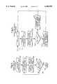
- FIG. 1An embodiment in accordance with the invention is shown in FIG. 1.
- FIG. 1there is shown a block diagram of a perceptual audio encoder with backward linear predictors, suitable for use with MPEG 1 algorithms.
- Pulse Code Modulated (PCM) audio stream 102is input to a filter 200 for dividing the input audio stream 102 into 32 frequency sub-bands 104 (1 . . . 32). It will be evident to a person skilled in the art that the input audio stream may be divided into a different number of frequency sub-bands. 32 sub-bands are described here in relation to MPEG-1. Simultaneously audio stream 102 is input to a psychoacoustic model 300 for determining the ratio of signal energy to the masking threshold for each sub-band 104.
- the filter 200may comprise any suitable filter such as a filter bank, micro processor or signal processing circuitry adapted to perform a Modified Discrete Cosine Transform (MDCT) or Fourier Transform for example, for providing means to filter audio stream 102.
- Sub-band samples 104(j) of the audio stream 102are input to respective backward linear predictors 400, also comprising Scalefactors 500, Quantizers 600 and Predictor Switch 900 circuitry, and to Psychoacoustic Model 300.
- Sub-band samples 104(j)are grouped together in frames of 12 samples for respective sub-bands, and the predictive coding is carried out on a frame by frame basis. Again, there need not be 12 samples but any number of samples suitable for the application for which the present invention is utilised.
- Psychoacoustic Model 300outputs so called mask-to-noise ratios (MNR) for each sub-band to a Dynamic Bit Allocator (DBA) 700.
- the DBA 700also has input to it signal-to-noise ratios (SNR) for each sub-band from Quantizer 600 for determining the apportioning of code bits for representing quantised samples and formulating this data and side information into a coded bitstream.
- Scale factor 500normalises respective sub-band samples 104(j) to the largest amplitude in each block of sub-band sample 104(j).
- Encoded signals for each sub-bandare then input to Multiplexor 800 where they are multiplexed together with the bit allocation information into serial data form by frame packing for example into MPEG format.
- the audio input stream 102comprises frames or blocks 202 of PCM samples. Typically for audio applications the PCM samples each comprise 16 to 24 bits.
- Audio input stream 102is input to filter 200 and psychoacoustic model 300.
- Filter 200transforms audio stream 102 frame by frame, from the time domain into the frequency domain.
- filter 200may comprise a filterbank, MDCT, Fourier Transform or any other suitable transform.
- the audio streamis transformed into 32 sub-band frequencies of the typical human audio range (up to 24 KHz).
- a single sub-band value 104(j)is output from filter 200.
- the sub-band valuesare grouped together in frames of 12 before being processed by Backward Predictors 400, Scale factor 500 and Quantizer 600.
- filter 200inputs a 12 ⁇ 32 sub-band sample matrix to Backward Predictors 400.
- Backward Predictors 400there is provided a backward Linear Predictor 400; Scale factor 500; and Quantiser 600; for each sub-band.
- the input signal to the jth predictoris represented by x j (n).
- the output (predicted) signal and quantised signalare represented by x j (n) and x j (n) respectively.
- the prediction error signal and quantised prediction error signalare represented by e j (n) and e j (n) respectively.
- Coefficients "a j "are the LPC coefficients for the jth sub-band, and the predictor has an order N. Typically, the predictor has an order of 50.
- the estimate or prediction of the current sampleis calculated by ##EQU1##
- the predictor error and the quantised signalare the predictor error and the quantised signal.
- Predictor c jcan be expressed as
- LMSLeast Mean Squares
- RLSRecursive Least Squares
- the LPC predictors "a"are updated once for each frame by performing LPC analysis on previously quantised sub-band signals. Updating once for each frame is valid since typically an audio signal is stationary over a frame.
- any suitable window functionmay be used preferably one which is adapted to yield optimum results.
- the described embodiment of the inventionuses the recursive algorithm which was proposed for Low Delay-Code Excited Linear PredictionLD-CELP and described in Chen et al "A fixed-point 16 kb/s LD-CELP algorithm," Proc. ICASSP, pp.21-24, 1991, incorporated herein by reference.
- LD-CELPa hybrid window is used for estimating the autocorrelation functions.
- the windowconsists of a recursive decaying tail and a section of non-recursive samples at the beginning.
- the tail of the windowis exponentially decaying with a decaying factor ⁇ slightly less than unity.
- the non-recursive part of the windowis a section of a sine function, for example, the decay function ⁇ may be 0.9705 where the length of the non-recursive part is 100.
- Each backward predictorproduces a predicted signal x j (n) given by equation (1) and a predictor gain G j given by equation (4)
- both the PCM audio bit stream 102 and the output 104 from Filterbank 200are input to the Psychacoustic Model 300.
- Psychoacoustic Model 300utilises the fact that the presence of an auditory stimulus may be masked by the presence of another auditory stimulus.
- the masking effectmay be a combination of the relative amplitudes and frequency of the stimuli, and even their chronological relationship. The net result is that certain auditory stimuli cannot be perceived by the human ear due to other auditory stimuli.
- Masking effectsare used to develop psychoacoustic models for example ISO/IEC 11172-3 (MPEG 1 Audio), incorporated herein by reference, which in turn are used to analyse input audio to determine what components are masked by other components.
- Psychoacoustic Model 300determines the ratio of the signal energy to masking threshold energy for each sample or block in sub-band 104(j) to give a signal to mask ratio SMR(j) for each sub-band, utilising any suitable psychoacoustic model.
- the masking properties of audio signalsare utilised such that masked signals are not transmitted or the available bits for quantisation are allocated in such a way that quantisation or coding noise is masked.
- Such controlis based on the signal to mask ratio (SMR), and signal to noise ratio (SNR) for the sub-bands evaluated by a corresponding quantising unit.
- SMRsignal to mask ratio
- SNRsignal to noise ratio
- Scale Factor 500(j) and Quantiser 600(j)operate on respective prediction error blocks of sub-band samples e j (n) as given by equation (2).
- SNR valuesmay be adapted in accordance with the prediction gain G j .
- the predictor itselfis identical at both encoder and decoder, the calculations of the estimate x j (n) of a current sample x j (n) as well as the calculations and adaptation of the predictor coefficients are exactly the same as in the decoder. The only difference is that on the encoder side the prediction error has to be calculated to be fed to the quantiser.
- the quantiser in MPEG-1 Layer Ias an example, the samples are first scaled by the scalefactor, which is the maximum value of all samples in that block, and then quantised by a uniform scalar quantiser. When backward predictor is used the scalefactor comes from the prediction errors.
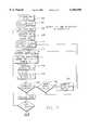
- FIG. 3there is provided a flow chart showing relevant steps for the Dynamic Bit Allocator 700 in allocating bits to encode and quantise sub-band signal samples in cooperation with Backward Predictors 400, Scalefactor 500, and Quantiser 600 in a closed loop system.
- Machine readable instructions in accordance with the flow chart of FIG. 3may be supplied to a microprocessor or digital signal processor thereby providing means for dynamically allocating bits.
- the closed loop bit allocationbegins at step 302 where the SNR for each sub-band block is initialised to zero.
- the Mask to Noise Ratio (MNR) for each sub-band blockis calculated in accordance with the following equation;
- SNR jis the SNR for the jth sub-band
- SMRis the Signal to Mask Ratio for the jth sub-band block calculated by the Psychoacoustic Model 300
- MNR jis the MNR for the jth sub-band block.
- bitsare allocated to encode each of the prediction error e l (n) in the Ith sub-band block, such that each prediction error has a further 1 bit allocated to it. For MPEG-1 this would require 12 bits since there are 12 samples per block.
- the first sampleis defined to be the current sample, and at step 312 the predicted value x l for the current sample is calculated. This is obtained from quantised samples in the previous block.
- the prediction error, e lfor the current sample is calculated in accordance with the following equation;
- e lis the prediction error for the current sample
- x lis the current sample
- x lis the predicted value for the current sample
- scale factor s lis based on the greatest e l value in a block and therefore requires knowledge of prediction errors for later samples in the current block. Clearly, such information is not yet available so the scale factor is determined from what prediction errors are known for the current block, step 316. For the first sample this is simply taking the first sample prediction error e l as the scale factor. The first sample prediction error e l and scale factor s l are quantised at step 318, and the quantised sample x l (n) is calculated.
- the quantised sampleis calculated in accordance with the following equation; ##EQU4## where x l is current quantised sample, e l is prediction error for current sample a l ,i is predictor coefficient for Ith sub-band, x l (n-i) is a previous quantised sample, and N is the predictor order.
- step 320if all the samples in the current frame are not yet quantised then the flow chart proceeds to step 322 where it is determined how to choose the scale factor calculated at step 316 is a new scale factor. If YES, the process flow goes to step 310 where the iterative process re-starts with the current sample being the first sample in the current block. If decision at 322 is NO then the next sample in the current block is designated the current sample, step 324. The process flow then goes to step 312 where the predicted value for the new current sample is evaluated.
- step 318For all samples having been quantised, the decision at step 318 is YES and the process continues to step 324 where the SNR for the Ith sub-band is calculated in accordance with the following equation; ##EQU5## where x l (n+i) is the ith sample in the I th block and x l (n+i) is the ith quantised sample in the Ith block.
- step 326If all bits available for allocation have been allocated then a YES decision is taken at step 326 and the closed loop bit allocation and quantisation routine ends. A NO decision at step 326 results in the process returning to step 304 where a new MNR for the Ith sub-band is calculated and it is determined which sub-band block has the lowest MNR I .
- FIG. 4there is shown a flow chart describing an open-loop bit allocation and quantisation process suitable for use in a preferred embodiment of the invention.
- An open-loop searchavoids the high computational complexity inherent in a closed-loop search. In the open-loop search any unquantised signal samples are substituted for corresponding quantised samples which are not yet available. Additionally, instead of the sub-band SNR being calculated, the prediction gain is calculated based on predicted signal samples.
- the prediction gainis evaluated in accordance with the following equation; ##EQU6## where x j (n+i) is the ith sample in the jth sub-band, x j (n+i) is the ith predicted sample in the jth sub-band and S N is the number of samples in a sample block.
- the MNR for each sub-bandis calculated in accordance with the following equation;
- MNR jis the mask to noise ratio
- SMR Jis the signal to mask ratio
- SNR jis the signal to noise ratio for jth sub-band
- G jis the prediction gain for the jth sub-band
- the sub-band sample block having the lowest MNR (MNR I )is identified.
- bitsare allocated for quantising prediction errors for the sample block having least MNR and, referred to as the Ith sample block.
- each of the twelve samples in the Ith blockhas one extra bit allocated to it for quantising the sample prediction error e l (n+i).
- a Predictor Switch 900for carrying out predictor control.
- the Predictor Switch 900is operable to detect transients in the audio signal and to invoke a lower order prediction routine to handle and recover from such transients.
- Predictor Switch 900is adapted to operate in accordance with the flow chart shown in FIG. 5.
- step 502the prediction gain for each sub-band block is calculated for all 32 sub-bands.
- step 504the sum of individual sub-band prediction gains is calculated to give the total block prediction gain, G T .
- step 506it is determined if the total block prediction gain, G T , is greater than a threshold prediction gain, G TH for the block. If G T is greater than G TH then the prediction process continues, but if G T less than G TH then a transient is indicated.
- G THis 20 dB, but may be adjusted according to the number of sub-bands employed in an embodiment of the invention or according to experimentation.
- step 506may comprise a test for a sudden drop in prediction gain as shown in the following equation;
- G previousis the total gain for the previous block and G TH ' is the difference threshold.
- step 506prediction will be utilised for that block, step 508. That is to say, high order prediction continues, or the transient recovery stepped prediction sequence is continued. However, if the decision is NO then the process goes to step 510 where the predictor for each sub-band is initialised for low order prediction, and the procedure reverts to the loop 502 whereby the low order prediction sub-routine is activated. From steps 508 and 510, the process proceeds to loop 502 where the predictor switch is initialised ready for the next block.
- a table for a low-order predictor sub-routine 510is shown in FIG. 6.
- Sub-routine 510is operable for each sub-band for which low-order prediction is to be used. When it is determined on a block basis that low-order prediction is to be used then sub-routine 510 is used for all sub-band predictors. If prediction is to be used on a block basis, then sub-routine 510 is only used for those sub-bands identified at step 502 for low-order prediction.
- Predictor control informationis included in side information which is transmitted with the actual encoded signal.
- the side informationincludes a frame prediction bit which indicates if prediction is being used (bit set) or not used (bit set 1) in the current frame. This bit is always present. If the bit is set 1 then prediction is switched off for the current frame and no further predictor side information is present. If the bit is set 0 then prediction is used for the current frame, and for each sub-band there is one bit which controls use of prediction in that sub-band. If the sub-band predictor bit is set 1 then low-order prediction is initiated for that sub-band, and the receiver enters sub-routine 510 described with reference to FIG. 6. If the sub-band predictor is set 0 then normal high order prediction continues. In the foregoing manner, the receiver Backward Predictor corresponding to the transmitter Backward Predictor can decode the signal to produce a corresponding audio signal.
- the scalefactorsconstitute the largest side information in the audio codec.
- Each sub-bandrequires six bits to represent the scalefactor if a sample prediction error is to be transmitted or that sub-band.
- scalefactors between successive framesare highly correlated.
- the scalefactorsmay be coded to take advantage of this time redundancy by means of predictive coding.
- closed-loop quantisationfor example, the optimal scalefactor and the corresponding SNR are obtained first.
- the scalefactor for the previous frameis then tested in the present frame. If the corresponding SNR using the previous frame's scalefactor is comparable to the SNR using the optimal scalefactor obtained during closed-loop quantisation for the present frame, i.e.,
- bit allocation informationrequire 128 bits side information, 4 bits for each sub-band.
- the side informationis reduced depending on the sampling frequency and bitrates.
- an adaptive schemeis used for bit allocation, specifically taking the consideration of low bitrate coding. To take account of this, firstly 4 bits are used to indicate the number of sub-bands in which no bits are allocated starting from the highest frequency band. Secondly, since the number of bits used in each sub-band is typically different, the bit allocation information is different for the sub-bands. For example, for the first ten sub-bands, 3 bits are used to represent 7 possible number of bits for quantising the samples in that sub-band. In the rest of the sub-bands, 2 bits are used to represent four possibilities. Experimental results show that using this bit allocation strategy, bit allocation side information is reduced to about 40 bits instead of 128 bits without any significant performance decrease.
- An audio decoder 950 suitable for use with an embodiment of the inventionis now described with reference to FIG. 7.
- Signals from a digital channel in, for example, MPEG formatare input to demultiplexor 902.
- Demultiplexor 902forwards prediction error signals for respective sub-bands 904 to dequantiser, descaler and backward predictor 908.
- Side information at 906such as bit allocation, scale factor and predictor switch information are forwarded to dynamic bit and scale factor decoder and predictor switch 910.
- the backward predictor in 908comprises the same algorithm as used for audio encoding in backward predictor 400.
- the prediction order used in 908is dependent upon the information provided by predictor switch 910.
- the backward predictor in 908functions in accordance with the table shown in FIG. 6. If the high order mode is current then the backward predictor in 908 operates with a high prediction order.
- the dequantised descaled and backward predicted signals respective sub-bands 912are output to filter bank 914 where the signal is reconstructed.
- Filter bank 914performs a substantially inverse operation to filter bank 200 described with reference to FIG. 1.
- Filter bank 914outputs a PCM output to what may be a conventional audion circuit.
- FIG. 8shows a communications network operable in accordance with embodiments of the present invention.
- a transmission unit 1002, comprising an audio encoder in accordance with the present inventionmay be coupled via a landline connection to a computer 1004, that computer having a decoder in accordance with the present invention.
- computer 1004may be part of a local area network where a single computer decodes input signals into a local data format for distribution on the local area network.
- Transmission unit 1002may also forward information to base station 1006 of a radio communication network for example.
- base station 1006may comprise an encoder in accordance with the present invention, or the data may already be encoded in transmission unit 1002.
- Signals from base station 1006may be received by a radio telephone 1008 or a mobile computer system 1010.
- Radio telephone 1008 and mobile computer 1010comprise a decoder in accordance with the present invention.
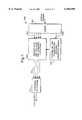
- FIG. 9shows diagrammatically the operation of the invention with respect to the coder, described herein above, and indicated at 1100.
- the coder 1100is part of a transmitter 1102 which communicates with a network 1103.
- the coder 1100operates upon an input signal on line 1104, and is operative at a high order prediction mode and a low order prediction mode resulting in the outputting of an encoded signal on line 1105 and a predictive coding gain on line 1106.
- the order of the prediction modeis selected by mode initiate signals outputted by a switch 1108 in response to an output of a detector 1110.
- the detector 1110is responsive to the coding gain on line 1106 to obtain information useful in the control of the switch 1108 to produce the mode initiation signals and also a mode indication signal.
- the input signal line 1104maybe connected to the detector 1110, as indicated by the dashed line, and the detector 1110 is operative to perform, for example, a half-frame power detection of the input signal to obtain information useful in the control of the switch 1108 to produce the mode initiation signals and the mode indication signal.
- the detector 1110detects a transient signal on line 1104, as by means of analysis of the coding gain or by the half-frame power detection, the switch 1108 is switched to produce a second mode initiation signal.
Landscapes
- Engineering & Computer Science (AREA)
- Physics & Mathematics (AREA)
- Spectroscopy & Molecular Physics (AREA)
- Computational Linguistics (AREA)
- Signal Processing (AREA)
- Health & Medical Sciences (AREA)
- Audiology, Speech & Language Pathology (AREA)
- Human Computer Interaction (AREA)
- Acoustics & Sound (AREA)
- Multimedia (AREA)
- Compression, Expansion, Code Conversion, And Decoders (AREA)
Abstract
Description
e.sub.j (n)=x.sub.j (n)-x.sub.j (n), (2)
x.sub.j (n)=x.sub.j (n)+e.sub.j (n) (3)
c.sub.j =R.sub.j.sup.-1 r.sub.j
x.sub.j '(n)=x.sub.j (n)w(n) (6).
MNR.sub.j =SNR.sub.j -SMR.sub.j (7)
e.sub.l =x.sub.l -x.sub.l (8)
MNR.sub.j =SNR.sub.j -SMR.sub.j -G.sub.j (12)
|G.sub.T -G.sub.previous |<G.sub.TH ' (13)
SNR.sup.previous >SNR.sup.present -C(dB)
Claims (20)
Applications Claiming Priority (2)
| Application Number | Priority Date | Filing Date | Title |
|---|---|---|---|
| GB9620457AGB2318029B (en) | 1996-10-01 | 1996-10-01 | Audio coding method and apparatus |
| GB9620457 | 1996-10-01 |
Publications (1)
| Publication Number | Publication Date |
|---|---|
| US6104996Atrue US6104996A (en) | 2000-08-15 |
Family
ID=10800772
Family Applications (1)
| Application Number | Title | Priority Date | Filing Date |
|---|---|---|---|
| US08/940,677Expired - LifetimeUS6104996A (en) | 1996-10-01 | 1997-09-30 | Audio coding with low-order adaptive prediction of transients |
Country Status (2)
| Country | Link |
|---|---|
| US (1) | US6104996A (en) |
| GB (1) | GB2318029B (en) |
Cited By (37)
| Publication number | Priority date | Publication date | Assignee | Title |
|---|---|---|---|---|
| US20010032087A1 (en)* | 2000-03-15 | 2001-10-18 | Oomen Arnoldus Werner Johannes | Audio coding |
| US6308150B1 (en)* | 1998-06-16 | 2001-10-23 | Matsushita Electric Industrial Co., Ltd. | Dynamic bit allocation apparatus and method for audio coding |
| US20030187663A1 (en)* | 2002-03-28 | 2003-10-02 | Truman Michael Mead | Broadband frequency translation for high frequency regeneration |
| US6678647B1 (en)* | 2000-06-02 | 2004-01-13 | Agere Systems Inc. | Perceptual coding of audio signals using cascaded filterbanks for performing irrelevancy reduction and redundancy reduction with different spectral/temporal resolution |
| US6725110B2 (en)* | 2000-05-26 | 2004-04-20 | Yamaha Corporation | Digital audio decoder |
| US6725192B1 (en)* | 1998-06-26 | 2004-04-20 | Ricoh Company, Ltd. | Audio coding and quantization method |
| US20040083097A1 (en)* | 2002-10-29 | 2004-04-29 | Chu Wai Chung | Optimized windows and interpolation factors, and methods for optimizing windows, interpolation factors and linear prediction analysis in the ITU-T G.729 speech coding standard |
| US6745162B1 (en)* | 2000-06-22 | 2004-06-01 | Sony Corporation | System and method for bit allocation in an audio encoder |
| US6766300B1 (en)* | 1996-11-07 | 2004-07-20 | Creative Technology Ltd. | Method and apparatus for transient detection and non-distortion time scaling |
| WO2004002040A3 (en)* | 2002-06-21 | 2004-07-29 | Thomson Licensing Sa | Broadcast router having a serial digital audio data stream decoder |
| US20040162720A1 (en)* | 2003-02-15 | 2004-08-19 | Samsung Electronics Co., Ltd. | Audio data encoding apparatus and method |
| US20040264416A1 (en)* | 2003-06-26 | 2004-12-30 | Ian Robinson | Communication system and method for improving efficiency and linearity |
| WO2005083683A1 (en)* | 2004-02-13 | 2005-09-09 | Fraunhofer-Gesellschaft zur Förderung der angewandten Forschung e.V. | Predicative coding scheme |
| WO2004097794A3 (en)* | 2003-04-30 | 2005-09-09 | Coding Tech Ab | Advanced processing based on a complex-exponential-modulated filterbank and adaptive time signalling methods |
| US6950794B1 (en) | 2001-11-20 | 2005-09-27 | Cirrus Logic, Inc. | Feedforward prediction of scalefactors based on allowable distortion for noise shaping in psychoacoustic-based compression |
| US20050256723A1 (en)* | 2004-05-14 | 2005-11-17 | Mansour Mohamed F | Efficient filter bank computation for audio coding |
| US20060069555A1 (en)* | 2004-09-13 | 2006-03-30 | Ittiam Systems (P) Ltd. | Method, system and apparatus for allocating bits in perceptual audio coders |
| US7047185B1 (en)* | 1998-09-15 | 2006-05-16 | Skyworks Solutions, Inc. | Method and apparatus for dynamically switching between speech coders of a mobile unit as a function of received signal quality |
| EP1580895A4 (en)* | 2002-11-21 | 2006-11-02 | Nippon Telegraph & Telephone | Digital signal processing method, processor thereof, program thereof, and recording medium containing the program |
| US20070011215A1 (en)* | 2005-07-11 | 2007-01-11 | Lg Electronics Inc. | Apparatus and method of encoding and decoding audio signal |
| US20070016427A1 (en)* | 2005-07-15 | 2007-01-18 | Microsoft Corporation | Coding and decoding scale factor information |
| US20070185706A1 (en)* | 2001-12-14 | 2007-08-09 | Microsoft Corporation | Quality improvement techniques in an audio encoder |
| US20080021704A1 (en)* | 2002-09-04 | 2008-01-24 | Microsoft Corporation | Quantization and inverse quantization for audio |
| US20080221908A1 (en)* | 2002-09-04 | 2008-09-11 | Microsoft Corporation | Multi-channel audio encoding and decoding |
| US7454327B1 (en)* | 1999-10-05 | 2008-11-18 | Fraunhofer-Gesellschaft Zur Foerderung Der Angewandtren Forschung E.V. | Method and apparatus for introducing information into a data stream and method and apparatus for encoding an audio signal |
| US20090012208A1 (en)* | 2003-10-07 | 2009-01-08 | Niels Joergen Madsen | Medical Device Having a Wetted Hydrophilic Coating |
| US20090024395A1 (en)* | 2004-01-19 | 2009-01-22 | Matsushita Electric Industrial Co., Ltd. | Audio signal encoding method, audio signal decoding method, transmitter, receiver, and wireless microphone system |
| US20090037166A1 (en)* | 2007-07-31 | 2009-02-05 | Wen-Haw Wang | Audio encoding method with function of accelerating a quantization iterative loop process |
| US20090254783A1 (en)* | 2006-05-12 | 2009-10-08 | Jens Hirschfeld | Information Signal Encoding |
| US20100318368A1 (en)* | 2002-09-04 | 2010-12-16 | Microsoft Corporation | Quantization and inverse quantization for audio |
| US7930171B2 (en) | 2001-12-14 | 2011-04-19 | Microsoft Corporation | Multi-channel audio encoding/decoding with parametric compression/decompression and weight factors |
| US20130107986A1 (en)* | 2011-11-01 | 2013-05-02 | Chao Tian | Method and apparatus for improving transmission of data on a bandwidth expanded channel |
| US20130107979A1 (en)* | 2011-11-01 | 2013-05-02 | Chao Tian | Method and apparatus for improving transmission on a bandwidth mismatched channel |
| EP2159790A4 (en)* | 2007-06-27 | 2016-04-06 | Nec Corp | AUDIO CODING METHOD, AUDIO CODING METHOD, AUDIO CODING DEVICE, AUDIO DEODICATION DEVICE, PROGRAM AND AUDIO CODING / DECODING SYSTEM |
| JP2017524980A (en)* | 2014-06-26 | 2017-08-31 | クゥアルコム・インコーポレイテッドQualcomm Incorporated | Time gain adjustment based on high-band signal characteristics |
| US10657973B2 (en)* | 2014-10-02 | 2020-05-19 | Sony Corporation | Method, apparatus and system |
| US11374666B2 (en)* | 2018-06-08 | 2022-06-28 | Nokia Technologies Oy | Noise floor estimation for signal detection |
Families Citing this family (3)
| Publication number | Priority date | Publication date | Assignee | Title |
|---|---|---|---|---|
| FI970553L (en)* | 1997-02-07 | 1998-08-08 | Nokia Mobile Phones Ltd | Audio coding method and device |
| US6012025A (en)* | 1998-01-28 | 2000-01-04 | Nokia Mobile Phones Limited | Audio coding method and apparatus using backward adaptive prediction |
| EP1052622B1 (en)* | 1999-05-11 | 2007-07-11 | Nippon Telegraph and Telephone Corporation | Selection of a synthesis filter for CELP type wideband audio coding |
Citations (10)
| Publication number | Priority date | Publication date | Assignee | Title |
|---|---|---|---|---|
| US4301329A (en)* | 1978-01-09 | 1981-11-17 | Nippon Electric Co., Ltd. | Speech analysis and synthesis apparatus |
| EP0532225A2 (en)* | 1991-09-10 | 1993-03-17 | AT&T Corp. | Method and apparatus for speech coding and decoding |
| EP0573398A2 (en)* | 1992-06-01 | 1993-12-08 | Hughes Aircraft Company | C.E.L.P. Vocoder |
| EP0599569A2 (en)* | 1992-11-26 | 1994-06-01 | Nokia Mobile Phones Ltd. | A method of coding a speech signal |
| US5321793A (en)* | 1992-07-31 | 1994-06-14 | SIP--Societa Italiana per l'Esercizio delle Telecommunicazioni P.A. | Low-delay audio signal coder, using analysis-by-synthesis techniques |
| US5339384A (en)* | 1992-02-18 | 1994-08-16 | At&T Bell Laboratories | Code-excited linear predictive coding with low delay for speech or audio signals |
| WO1995028824A2 (en)* | 1994-04-15 | 1995-11-02 | Hughes Aircraft Company | Method of encoding a signal containing speech |
| US5511093A (en)* | 1993-06-05 | 1996-04-23 | Robert Bosch Gmbh | Method for reducing data in a multi-channel data transmission |
| US5515397A (en)* | 1991-06-19 | 1996-05-07 | Telefonaktiebolaget Lm Ericsson | PCM subcode communications technique between a regional radio transmitter/receiver and a regional switching center |
| US5557639A (en)* | 1993-10-11 | 1996-09-17 | Nokia Mobile Phones Ltd. | Enhanced decoder for a radio telephone |
- 1996
- 1996-10-01GBGB9620457Apatent/GB2318029B/ennot_activeExpired - Lifetime
- 1997
- 1997-09-30USUS08/940,677patent/US6104996A/ennot_activeExpired - Lifetime
Patent Citations (11)
| Publication number | Priority date | Publication date | Assignee | Title |
|---|---|---|---|---|
| US4301329A (en)* | 1978-01-09 | 1981-11-17 | Nippon Electric Co., Ltd. | Speech analysis and synthesis apparatus |
| US5515397A (en)* | 1991-06-19 | 1996-05-07 | Telefonaktiebolaget Lm Ericsson | PCM subcode communications technique between a regional radio transmitter/receiver and a regional switching center |
| EP0532225A2 (en)* | 1991-09-10 | 1993-03-17 | AT&T Corp. | Method and apparatus for speech coding and decoding |
| US5339384A (en)* | 1992-02-18 | 1994-08-16 | At&T Bell Laboratories | Code-excited linear predictive coding with low delay for speech or audio signals |
| EP0573398A2 (en)* | 1992-06-01 | 1993-12-08 | Hughes Aircraft Company | C.E.L.P. Vocoder |
| US5321793A (en)* | 1992-07-31 | 1994-06-14 | SIP--Societa Italiana per l'Esercizio delle Telecommunicazioni P.A. | Low-delay audio signal coder, using analysis-by-synthesis techniques |
| EP0599569A2 (en)* | 1992-11-26 | 1994-06-01 | Nokia Mobile Phones Ltd. | A method of coding a speech signal |
| US5596677A (en)* | 1992-11-26 | 1997-01-21 | Nokia Mobile Phones Ltd. | Methods and apparatus for coding a speech signal using variable order filtering |
| US5511093A (en)* | 1993-06-05 | 1996-04-23 | Robert Bosch Gmbh | Method for reducing data in a multi-channel data transmission |
| US5557639A (en)* | 1993-10-11 | 1996-09-17 | Nokia Mobile Phones Ltd. | Enhanced decoder for a radio telephone |
| WO1995028824A2 (en)* | 1994-04-15 | 1995-11-02 | Hughes Aircraft Company | Method of encoding a signal containing speech |
Non-Patent Citations (8)
| Title |
|---|
| "A Differential Perceptual Audio Coding Method With Reduced Bitrate Requirements", Paraskevas et al, IEEE Transactions on Speech And Audio Processing, vol. 3, No. 6, Nov. 1995. |
| "A Fixed-Point 16kb/s LD-CELP Algorithm", Chen et al., Proc. ICASSP, pp. 21-24, 1991. |
| "Improving MPEG Audio Coding By Backward Adaptive Linear Stereo Prediction", Fuchs et al., AES Convention, N.Y., Preprint No. 4086 Oct. 1995. |
| "Transform Coding Of Audio Signals Using Correlation Between Successive Transform Blocks", Mahieux et al., Proc. ICASSP, 1989, pp. 2021-2024. |
| A Differential Perceptual Audio Coding Method With Reduced Bitrate Requirements , Paraskevas et al, IEEE Transactions on Speech And Audio Processing, vol. 3, No. 6, Nov. 1995.* |
| A Fixed Point 16kb/s LD CELP Algorithm , Chen et al., Proc. ICASSP, pp. 21 24, 1991.* |
| Improving MPEG Audio Coding By Backward Adaptive Linear Stereo Prediction , Fuchs et al., AES Convention, N.Y., Preprint No. 4086 Oct. 1995.* |
| Transform Coding Of Audio Signals Using Correlation Between Successive Transform Blocks , Mahieux et al., Proc. ICASSP, 1989, pp. 2021 2024.* |
Cited By (171)
| Publication number | Priority date | Publication date | Assignee | Title |
|---|---|---|---|---|
| US6766300B1 (en)* | 1996-11-07 | 2004-07-20 | Creative Technology Ltd. | Method and apparatus for transient detection and non-distortion time scaling |
| US6308150B1 (en)* | 1998-06-16 | 2001-10-23 | Matsushita Electric Industrial Co., Ltd. | Dynamic bit allocation apparatus and method for audio coding |
| US6725192B1 (en)* | 1998-06-26 | 2004-04-20 | Ricoh Company, Ltd. | Audio coding and quantization method |
| US7047185B1 (en)* | 1998-09-15 | 2006-05-16 | Skyworks Solutions, Inc. | Method and apparatus for dynamically switching between speech coders of a mobile unit as a function of received signal quality |
| US20090138259A1 (en)* | 1999-10-05 | 2009-05-28 | Fraunhofer-Gesellschaft Zur Foerderung Der Angewandten Forschung E.V. | Method and Apparatus for Introducing Information into a Data Stream and Method and Apparatus for Encoding an Audio Signal |
| US20090076801A1 (en)* | 1999-10-05 | 2009-03-19 | Christian Neubauer | Method and Apparatus for Introducing Information into a Data Stream and Method and Apparatus for Encoding an Audio Signal |
| US7454327B1 (en)* | 1999-10-05 | 2008-11-18 | Fraunhofer-Gesellschaft Zur Foerderung Der Angewandtren Forschung E.V. | Method and apparatus for introducing information into a data stream and method and apparatus for encoding an audio signal |
| US8117027B2 (en) | 1999-10-05 | 2012-02-14 | Fraunhofer-Gesellschaft Zur Foerderung Der Angewandten Forschung E.V. | Method and apparatus for introducing information into a data stream and method and apparatus for encoding an audio signal |
| US20010032087A1 (en)* | 2000-03-15 | 2001-10-18 | Oomen Arnoldus Werner Johannes | Audio coding |
| US7499852B2 (en) | 2000-03-15 | 2009-03-03 | Koninklijke Philips Electronics N.V. | Audio coding using a shape function |
| US6925434B2 (en)* | 2000-03-15 | 2005-08-02 | Koninklijke Philips Electronics N.V. | Audio coding |
| US6725110B2 (en)* | 2000-05-26 | 2004-04-20 | Yamaha Corporation | Digital audio decoder |
| US6678647B1 (en)* | 2000-06-02 | 2004-01-13 | Agere Systems Inc. | Perceptual coding of audio signals using cascaded filterbanks for performing irrelevancy reduction and redundancy reduction with different spectral/temporal resolution |
| US6745162B1 (en)* | 2000-06-22 | 2004-06-01 | Sony Corporation | System and method for bit allocation in an audio encoder |
| US6950794B1 (en) | 2001-11-20 | 2005-09-27 | Cirrus Logic, Inc. | Feedforward prediction of scalefactors based on allowable distortion for noise shaping in psychoacoustic-based compression |
| US7930171B2 (en) | 2001-12-14 | 2011-04-19 | Microsoft Corporation | Multi-channel audio encoding/decoding with parametric compression/decompression and weight factors |
| US7917369B2 (en) | 2001-12-14 | 2011-03-29 | Microsoft Corporation | Quality improvement techniques in an audio encoder |
| US20070185706A1 (en)* | 2001-12-14 | 2007-08-09 | Microsoft Corporation | Quality improvement techniques in an audio encoder |
| US8428943B2 (en) | 2001-12-14 | 2013-04-23 | Microsoft Corporation | Quantization matrices for digital audio |
| US9305558B2 (en) | 2001-12-14 | 2016-04-05 | Microsoft Technology Licensing, Llc | Multi-channel audio encoding/decoding with parametric compression/decompression and weight factors |
| US8457956B2 (en) | 2002-03-28 | 2013-06-04 | Dolby Laboratories Licensing Corporation | Reconstructing an audio signal by spectral component regeneration and noise blending |
| US9324328B2 (en) | 2002-03-28 | 2016-04-26 | Dolby Laboratories Licensing Corporation | Reconstructing an audio signal with a noise parameter |
| US9767816B2 (en) | 2002-03-28 | 2017-09-19 | Dolby Laboratories Licensing Corporation | High frequency regeneration of an audio signal with phase adjustment |
| US9704496B2 (en) | 2002-03-28 | 2017-07-11 | Dolby Laboratories Licensing Corporation | High frequency regeneration of an audio signal with phase adjustment |
| US9653085B2 (en) | 2002-03-28 | 2017-05-16 | Dolby Laboratories Licensing Corporation | Reconstructing an audio signal having a baseband and high frequency components above the baseband |
| US9548060B1 (en) | 2002-03-28 | 2017-01-17 | Dolby Laboratories Licensing Corporation | High frequency regeneration of an audio signal with temporal shaping |
| US9466306B1 (en) | 2002-03-28 | 2016-10-11 | Dolby Laboratories Licensing Corporation | High frequency regeneration of an audio signal with temporal shaping |
| US9412388B1 (en) | 2002-03-28 | 2016-08-09 | Dolby Laboratories Licensing Corporation | High frequency regeneration of an audio signal with temporal shaping |
| US9412383B1 (en) | 2002-03-28 | 2016-08-09 | Dolby Laboratories Licensing Corporation | High frequency regeneration of an audio signal by copying in a circular manner |
| US9412389B1 (en) | 2002-03-28 | 2016-08-09 | Dolby Laboratories Licensing Corporation | High frequency regeneration of an audio signal by copying in a circular manner |
| US9343071B2 (en) | 2002-03-28 | 2016-05-17 | Dolby Laboratories Licensing Corporation | Reconstructing an audio signal with a noise parameter |
| US10269362B2 (en) | 2002-03-28 | 2019-04-23 | Dolby Laboratories Licensing Corporation | Methods, apparatus and systems for determining reconstructed audio signal |
| US9947328B2 (en) | 2002-03-28 | 2018-04-17 | Dolby Laboratories Licensing Corporation | Methods, apparatus and systems for determining reconstructed audio signal |
| US9177564B2 (en) | 2002-03-28 | 2015-11-03 | Dolby Laboratories Licensing Corporation | Reconstructing an audio signal by spectral component regeneration and noise blending |
| US8285543B2 (en) | 2002-03-28 | 2012-10-09 | Dolby Laboratories Licensing Corporation | Circular frequency translation with noise blending |
| US10529347B2 (en) | 2002-03-28 | 2020-01-07 | Dolby Laboratories Licensing Corporation | Methods, apparatus and systems for determining reconstructed audio signal |
| US20030187663A1 (en)* | 2002-03-28 | 2003-10-02 | Truman Michael Mead | Broadband frequency translation for high frequency regeneration |
| US8126709B2 (en) | 2002-03-28 | 2012-02-28 | Dolby Laboratories Licensing Corporation | Broadband frequency translation for high frequency regeneration |
| CN101072078B (en)* | 2002-06-21 | 2011-08-24 | 汤姆森特许公司 | Two-phase decoder for decoding AES-3 digital audio streams |
| CN1324557C (en)* | 2002-06-21 | 2007-07-04 | 汤姆森特许公司 | Method for extracting digital audio data words from serialized digital audio data stream |
| WO2004002040A3 (en)* | 2002-06-21 | 2004-07-29 | Thomson Licensing Sa | Broadcast router having a serial digital audio data stream decoder |
| US7747447B2 (en)* | 2002-06-21 | 2010-06-29 | Thomson Licensing | Broadcast router having a serial digital audio data stream decoder |
| US20050228646A1 (en)* | 2002-06-21 | 2005-10-13 | Carl Christensen | Broadcast router having a serial digital audio data stream decoder |
| US20080021704A1 (en)* | 2002-09-04 | 2008-01-24 | Microsoft Corporation | Quantization and inverse quantization for audio |
| US8069050B2 (en) | 2002-09-04 | 2011-11-29 | Microsoft Corporation | Multi-channel audio encoding and decoding |
| US20080221908A1 (en)* | 2002-09-04 | 2008-09-11 | Microsoft Corporation | Multi-channel audio encoding and decoding |
| US20110060597A1 (en)* | 2002-09-04 | 2011-03-10 | Microsoft Corporation | Multi-channel audio encoding and decoding |
| US7801735B2 (en) | 2002-09-04 | 2010-09-21 | Microsoft Corporation | Compressing and decompressing weight factors using temporal prediction for audio data |
| US20100318368A1 (en)* | 2002-09-04 | 2010-12-16 | Microsoft Corporation | Quantization and inverse quantization for audio |
| US20110054916A1 (en)* | 2002-09-04 | 2011-03-03 | Microsoft Corporation | Multi-channel audio encoding and decoding |
| US8255234B2 (en) | 2002-09-04 | 2012-08-28 | Microsoft Corporation | Quantization and inverse quantization for audio |
| US8255230B2 (en) | 2002-09-04 | 2012-08-28 | Microsoft Corporation | Multi-channel audio encoding and decoding |
| US8620674B2 (en) | 2002-09-04 | 2013-12-31 | Microsoft Corporation | Multi-channel audio encoding and decoding |
| US7502743B2 (en) | 2002-09-04 | 2009-03-10 | Microsoft Corporation | Multi-channel audio encoding and decoding with multi-channel transform selection |
| US8099292B2 (en) | 2002-09-04 | 2012-01-17 | Microsoft Corporation | Multi-channel audio encoding and decoding |
| US7860720B2 (en) | 2002-09-04 | 2010-12-28 | Microsoft Corporation | Multi-channel audio encoding and decoding with different window configurations |
| US8386269B2 (en) | 2002-09-04 | 2013-02-26 | Microsoft Corporation | Multi-channel audio encoding and decoding |
| US8069052B2 (en) | 2002-09-04 | 2011-11-29 | Microsoft Corporation | Quantization and inverse quantization for audio |
| US20070055503A1 (en)* | 2002-10-29 | 2007-03-08 | Docomo Communications Laboratories Usa, Inc. | Optimized windows and interpolation factors, and methods for optimizing windows, interpolation factors and linear prediction analysis in the ITU-T G.729 speech coding standard |
| US20040083097A1 (en)* | 2002-10-29 | 2004-04-29 | Chu Wai Chung | Optimized windows and interpolation factors, and methods for optimizing windows, interpolation factors and linear prediction analysis in the ITU-T G.729 speech coding standard |
| EP1580895A4 (en)* | 2002-11-21 | 2006-11-02 | Nippon Telegraph & Telephone | Digital signal processing method, processor thereof, program thereof, and recording medium containing the program |
| US20040162720A1 (en)* | 2003-02-15 | 2004-08-19 | Samsung Electronics Co., Ltd. | Audio data encoding apparatus and method |
| US7487097B2 (en) | 2003-04-30 | 2009-02-03 | Coding Technologies Ab | Advanced processing based on a complex-exponential-modulated filterbank and adaptive time signalling methods |
| WO2004097794A3 (en)* | 2003-04-30 | 2005-09-09 | Coding Tech Ab | Advanced processing based on a complex-exponential-modulated filterbank and adaptive time signalling methods |
| US7564978B2 (en) | 2003-04-30 | 2009-07-21 | Coding Technologies Ab | Advanced processing based on a complex-exponential-modulated filterbank and adaptive time signalling methods |
| US20070121952A1 (en)* | 2003-04-30 | 2007-05-31 | Jonas Engdegard | Advanced processing based on a complex-exponential-modulated filterbank and adaptive time signalling methods |
| US20060053018A1 (en)* | 2003-04-30 | 2006-03-09 | Jonas Engdegard | Advanced processing based on a complex-exponential-modulated filterbank and adaptive time signalling methods |
| US20040264416A1 (en)* | 2003-06-26 | 2004-12-30 | Ian Robinson | Communication system and method for improving efficiency and linearity |
| US20090245226A1 (en)* | 2003-06-26 | 2009-10-01 | Ian Robinson | Communication System and Method for Improving Efficiency and Linearity |
| US7580476B2 (en)* | 2003-06-26 | 2009-08-25 | Northrop Grumman Corporation | Communication system and method for improving efficiency and linearity |
| US8345796B2 (en) | 2003-06-26 | 2013-01-01 | Northrop Grumman Systems Corporation | Communication system and method for improving efficiency and linearity |
| US20090012208A1 (en)* | 2003-10-07 | 2009-01-08 | Niels Joergen Madsen | Medical Device Having a Wetted Hydrophilic Coating |
| US20090024395A1 (en)* | 2004-01-19 | 2009-01-22 | Matsushita Electric Industrial Co., Ltd. | Audio signal encoding method, audio signal decoding method, transmitter, receiver, and wireless microphone system |
| AU2004316541B2 (en)* | 2004-02-13 | 2008-04-24 | Fraunhofer-Gesellschaft Zur Foerderung Der Angewandten Forschung E.V. | Predicative coding scheme |
| CN1914670B (en)* | 2004-02-13 | 2011-03-23 | 弗兰霍菲尔运输应用研究公司 | Method and device for predictive coding and decoding predictive coding |
| WO2005083683A1 (en)* | 2004-02-13 | 2005-09-09 | Fraunhofer-Gesellschaft zur Förderung der angewandten Forschung e.V. | Predicative coding scheme |
| NO338722B1 (en)* | 2004-02-13 | 2016-10-10 | Fraunhofer Ges Forschung | Predictive coding and decoding |
| US20070016409A1 (en)* | 2004-02-13 | 2007-01-18 | Gerald Schuller | Predictive coding scheme |
| US7386446B2 (en) | 2004-02-13 | 2008-06-10 | Fraunhofer-Gesellschaft Zur Foerderung Der Angewandten Forschung E.V. | Predictive coding scheme with adaptive speed parameters |
| KR100852483B1 (en) | 2004-02-13 | 2008-08-18 | 프라운호퍼-게젤샤프트 츄어 푀르더룽 데어 안게반텐 포르슝에.파우. | Predictive coding scheme |
| RU2345426C2 (en)* | 2004-02-13 | 2009-01-27 | Фраунхофер-Гезелльшафт Цур Фердерунг Дер Ангевандтен Форшунг Е.Ф. | Predictive encoding scheme |
| US7512536B2 (en)* | 2004-05-14 | 2009-03-31 | Texas Instruments Incorporated | Efficient filter bank computation for audio coding |
| US20050256723A1 (en)* | 2004-05-14 | 2005-11-17 | Mansour Mohamed F | Efficient filter bank computation for audio coding |
| US20060069555A1 (en)* | 2004-09-13 | 2006-03-30 | Ittiam Systems (P) Ltd. | Method, system and apparatus for allocating bits in perceptual audio coders |
| US7725313B2 (en)* | 2004-09-13 | 2010-05-25 | Ittiam Systems (P) Ltd. | Method, system and apparatus for allocating bits in perceptual audio coders |
| US8149878B2 (en) | 2005-07-11 | 2012-04-03 | Lg Electronics Inc. | Apparatus and method of encoding and decoding audio signal |
| US7930177B2 (en) | 2005-07-11 | 2011-04-19 | Lg Electronics Inc. | Apparatus and method of encoding and decoding audio signals using hierarchical block switching and linear prediction coding |
| US7835917B2 (en) | 2005-07-11 | 2010-11-16 | Lg Electronics Inc. | Apparatus and method of processing an audio signal |
| US20090037167A1 (en)* | 2005-07-11 | 2009-02-05 | Tilman Liebchen | Apparatus and method of encoding and decoding audio signal |
| US20090037183A1 (en)* | 2005-07-11 | 2009-02-05 | Tilman Liebchen | Apparatus and method of encoding and decoding audio signal |
| US20090106032A1 (en)* | 2005-07-11 | 2009-04-23 | Tilman Liebchen | Apparatus and method of processing an audio signal |
| US20090037191A1 (en)* | 2005-07-11 | 2009-02-05 | Tilman Liebchen | Apparatus and method of encoding and decoding audio signal |
| US20090037184A1 (en)* | 2005-07-11 | 2009-02-05 | Tilman Liebchen | Apparatus and method of encoding and decoding audio signal |
| US20090037188A1 (en)* | 2005-07-11 | 2009-02-05 | Tilman Liebchen | Apparatus and method of encoding and decoding audio signals |
| US20090030701A1 (en)* | 2005-07-11 | 2009-01-29 | Tilman Liebchen | Apparatus and method of encoding and decoding audio signal |
| US20090037009A1 (en)* | 2005-07-11 | 2009-02-05 | Tilman Liebchen | Apparatus and method of processing an audio signal |
| US7949014B2 (en) | 2005-07-11 | 2011-05-24 | Lg Electronics Inc. | Apparatus and method of encoding and decoding audio signal |
| US7962332B2 (en) | 2005-07-11 | 2011-06-14 | Lg Electronics Inc. | Apparatus and method of encoding and decoding audio signal |
| US7966190B2 (en)* | 2005-07-11 | 2011-06-21 | Lg Electronics Inc. | Apparatus and method for processing an audio signal using linear prediction |
| US7987009B2 (en) | 2005-07-11 | 2011-07-26 | Lg Electronics Inc. | Apparatus and method of encoding and decoding audio signals |
| US7987008B2 (en) | 2005-07-11 | 2011-07-26 | Lg Electronics Inc. | Apparatus and method of processing an audio signal |
| US7991012B2 (en) | 2005-07-11 | 2011-08-02 | Lg Electronics Inc. | Apparatus and method of encoding and decoding audio signal |
| US7991272B2 (en) | 2005-07-11 | 2011-08-02 | Lg Electronics Inc. | Apparatus and method of processing an audio signal |
| US7996216B2 (en) | 2005-07-11 | 2011-08-09 | Lg Electronics Inc. | Apparatus and method of encoding and decoding audio signal |
| US20090037181A1 (en)* | 2005-07-11 | 2009-02-05 | Tilman Liebchen | Apparatus and method of encoding and decoding audio signal |
| US8010372B2 (en) | 2005-07-11 | 2011-08-30 | Lg Electronics Inc. | Apparatus and method of encoding and decoding audio signal |
| US8032368B2 (en) | 2005-07-11 | 2011-10-04 | Lg Electronics Inc. | Apparatus and method of encoding and decoding audio signals using hierarchical block swithcing and linear prediction coding |
| US8255227B2 (en) | 2005-07-11 | 2012-08-28 | Lg Electronics, Inc. | Scalable encoding and decoding of multichannel audio with up to five levels in subdivision hierarchy |
| US8032386B2 (en) | 2005-07-11 | 2011-10-04 | Lg Electronics Inc. | Apparatus and method of processing an audio signal |
| US8046092B2 (en) | 2005-07-11 | 2011-10-25 | Lg Electronics Inc. | Apparatus and method of encoding and decoding audio signal |
| US8050915B2 (en) | 2005-07-11 | 2011-11-01 | Lg Electronics Inc. | Apparatus and method of encoding and decoding audio signals using hierarchical block switching and linear prediction coding |
| US8055507B2 (en)* | 2005-07-11 | 2011-11-08 | Lg Electronics Inc. | Apparatus and method for processing an audio signal using linear prediction |
| US8065158B2 (en) | 2005-07-11 | 2011-11-22 | Lg Electronics Inc. | Apparatus and method of processing an audio signal |
| US20090037187A1 (en)* | 2005-07-11 | 2009-02-05 | Tilman Liebchen | Apparatus and method of encoding and decoding audio signals |
| US20090037185A1 (en)* | 2005-07-11 | 2009-02-05 | Tilman Liebchen | Apparatus and method of encoding and decoding audio signal |
| US20090030675A1 (en)* | 2005-07-11 | 2009-01-29 | Tilman Liebchen | Apparatus and method of encoding and decoding audio signal |
| US8108219B2 (en) | 2005-07-11 | 2012-01-31 | Lg Electronics Inc. | Apparatus and method of encoding and decoding audio signal |
| US20090030700A1 (en)* | 2005-07-11 | 2009-01-29 | Tilman Liebchen | Apparatus and method of encoding and decoding audio signal |
| US8121836B2 (en) | 2005-07-11 | 2012-02-21 | Lg Electronics Inc. | Apparatus and method of processing an audio signal |
| US20090030702A1 (en)* | 2005-07-11 | 2009-01-29 | Tilman Liebchen | Apparatus and method of encoding and decoding audio signal |
| US8149877B2 (en) | 2005-07-11 | 2012-04-03 | Lg Electronics Inc. | Apparatus and method of encoding and decoding audio signal |
| US8149876B2 (en) | 2005-07-11 | 2012-04-03 | Lg Electronics Inc. | Apparatus and method of encoding and decoding audio signal |
| US20090055198A1 (en)* | 2005-07-11 | 2009-02-26 | Tilman Liebchen | Apparatus and method of processing an audio signal |
| US8155153B2 (en) | 2005-07-11 | 2012-04-10 | Lg Electronics Inc. | Apparatus and method of encoding and decoding audio signal |
| US8155144B2 (en) | 2005-07-11 | 2012-04-10 | Lg Electronics Inc. | Apparatus and method of encoding and decoding audio signal |
| US8155152B2 (en) | 2005-07-11 | 2012-04-10 | Lg Electronics Inc. | Apparatus and method of encoding and decoding audio signal |
| US8180631B2 (en) | 2005-07-11 | 2012-05-15 | Lg Electronics Inc. | Apparatus and method of processing an audio signal, utilizing a unique offset associated with each coded-coefficient |
| US8032240B2 (en) | 2005-07-11 | 2011-10-04 | Lg Electronics Inc. | Apparatus and method of processing an audio signal |
| US20090048850A1 (en)* | 2005-07-11 | 2009-02-19 | Tilman Liebchen | Apparatus and method of processing an audio signal |
| US7830921B2 (en) | 2005-07-11 | 2010-11-09 | Lg Electronics Inc. | Apparatus and method of encoding and decoding audio signal |
| US20090030703A1 (en)* | 2005-07-11 | 2009-01-29 | Tilman Liebchen | Apparatus and method of encoding and decoding audio signal |
| US8275476B2 (en) | 2005-07-11 | 2012-09-25 | Lg Electronics Inc. | Apparatus and method of encoding and decoding audio signals |
| US20090037192A1 (en)* | 2005-07-11 | 2009-02-05 | Tilman Liebchen | Apparatus and method of processing an audio signal |
| US8326132B2 (en) | 2005-07-11 | 2012-12-04 | Lg Electronics Inc. | Apparatus and method of encoding and decoding audio signal |
| US20070011215A1 (en)* | 2005-07-11 | 2007-01-11 | Lg Electronics Inc. | Apparatus and method of encoding and decoding audio signal |
| US20090037190A1 (en)* | 2005-07-11 | 2009-02-05 | Tilman Liebchen | Apparatus and method of encoding and decoding audio signal |
| US8417100B2 (en) | 2005-07-11 | 2013-04-09 | Lg Electronics Inc. | Apparatus and method of encoding and decoding audio signal |
| US20090037186A1 (en)* | 2005-07-11 | 2009-02-05 | Tilman Liebchen | Apparatus and method of encoding and decoding audio signal |
| US20070010995A1 (en)* | 2005-07-11 | 2007-01-11 | Lg Electronics Inc. | Apparatus and method of encoding and decoding audio signal |
| US20070009032A1 (en)* | 2005-07-11 | 2007-01-11 | Lg Electronics Inc. | Apparatus and method of encoding and decoding audio signal |
| US20070009227A1 (en)* | 2005-07-11 | 2007-01-11 | Lg Electronics Inc. | Apparatus and method of processing an audio signal |
| US8510119B2 (en) | 2005-07-11 | 2013-08-13 | Lg Electronics Inc. | Apparatus and method of processing an audio signal, utilizing unique offsets associated with coded-coefficients |
| US8510120B2 (en) | 2005-07-11 | 2013-08-13 | Lg Electronics Inc. | Apparatus and method of processing an audio signal, utilizing unique offsets associated with coded-coefficients |
| US8554568B2 (en) | 2005-07-11 | 2013-10-08 | Lg Electronics Inc. | Apparatus and method of processing an audio signal, utilizing unique offsets associated with each coded-coefficients |
| US20070014297A1 (en)* | 2005-07-11 | 2007-01-18 | Lg Electronics Inc. | Apparatus and method of encoding and decoding audio signal |
| US20070011000A1 (en)* | 2005-07-11 | 2007-01-11 | Lg Electronics Inc. | Apparatus and method of processing an audio signal |
| US20090048851A1 (en)* | 2005-07-11 | 2009-02-19 | Tilman Liebchen | Apparatus and method of encoding and decoding audio signal |
| US20070009233A1 (en)* | 2005-07-11 | 2007-01-11 | Lg Electronics Inc. | Apparatus and method of processing an audio signal |
| US20070009105A1 (en)* | 2005-07-11 | 2007-01-11 | Lg Electronics Inc. | Apparatus and method of encoding and decoding audio signal |
| US20070011013A1 (en)* | 2005-07-11 | 2007-01-11 | Lg Electronics Inc. | Apparatus and method of processing an audio signal |
| US20070009033A1 (en)* | 2005-07-11 | 2007-01-11 | Lg Electronics Inc. | Apparatus and method of processing an audio signal |
| US20070009031A1 (en)* | 2005-07-11 | 2007-01-11 | Lg Electronics Inc. | Apparatus and method of encoding and decoding audio signal |
| US20070011004A1 (en)* | 2005-07-11 | 2007-01-11 | Lg Electronics Inc. | Apparatus and method of processing an audio signal |
| US20070010996A1 (en)* | 2005-07-11 | 2007-01-11 | Lg Electronics Inc. | Apparatus and method of encoding and decoding audio signal |
| US20070016427A1 (en)* | 2005-07-15 | 2007-01-18 | Microsoft Corporation | Coding and decoding scale factor information |
| US7539612B2 (en)* | 2005-07-15 | 2009-05-26 | Microsoft Corporation | Coding and decoding scale factor information |
| US9754601B2 (en)* | 2006-05-12 | 2017-09-05 | Fraunhofer-Gesellschaft Zur Foerderung Der Angewandten Forschung E.V. | Information signal encoding using a forward-adaptive prediction and a backwards-adaptive quantization |
| US20090254783A1 (en)* | 2006-05-12 | 2009-10-08 | Jens Hirschfeld | Information Signal Encoding |
| US10446162B2 (en) | 2006-05-12 | 2019-10-15 | Fraunhofer-Gesellschaft Zur Foerderung Der Angewandten Forschung E.V. | System, method, and non-transitory computer readable medium storing a program utilizing a postfilter for filtering a prefiltered audio signal in a decoder |
| EP2159790A4 (en)* | 2007-06-27 | 2016-04-06 | Nec Corp | AUDIO CODING METHOD, AUDIO CODING METHOD, AUDIO CODING DEVICE, AUDIO DEODICATION DEVICE, PROGRAM AND AUDIO CODING / DECODING SYSTEM |
| US20090037166A1 (en)* | 2007-07-31 | 2009-02-05 | Wen-Haw Wang | Audio encoding method with function of accelerating a quantization iterative loop process |
| US8255232B2 (en) | 2007-07-31 | 2012-08-28 | Realtek Semiconductor Corp. | Audio encoding method with function of accelerating a quantization iterative loop process |
| US9356627B2 (en) | 2011-11-01 | 2016-05-31 | At&T Intellectual Property I, L.P. | Method and apparatus for improving transmission of data on a bandwidth mismatched channel |
| US20130107986A1 (en)* | 2011-11-01 | 2013-05-02 | Chao Tian | Method and apparatus for improving transmission of data on a bandwidth expanded channel |
| US9356629B2 (en) | 2011-11-01 | 2016-05-31 | At&T Intellectual Property I, L.P. | Method and apparatus for improving transmission of data on a bandwidth expanded channel |
| US8781023B2 (en)* | 2011-11-01 | 2014-07-15 | At&T Intellectual Property I, L.P. | Method and apparatus for improving transmission of data on a bandwidth expanded channel |
| US20130107979A1 (en)* | 2011-11-01 | 2013-05-02 | Chao Tian | Method and apparatus for improving transmission on a bandwidth mismatched channel |
| US8774308B2 (en)* | 2011-11-01 | 2014-07-08 | At&T Intellectual Property I, L.P. | Method and apparatus for improving transmission of data on a bandwidth mismatched channel |
| JP2017524980A (en)* | 2014-06-26 | 2017-08-31 | クゥアルコム・インコーポレイテッドQualcomm Incorporated | Time gain adjustment based on high-band signal characteristics |
| US10657973B2 (en)* | 2014-10-02 | 2020-05-19 | Sony Corporation | Method, apparatus and system |
| US11374666B2 (en)* | 2018-06-08 | 2022-06-28 | Nokia Technologies Oy | Noise floor estimation for signal detection |
Also Published As
| Publication number | Publication date |
|---|---|
| GB9620457D0 (en) | 1996-11-20 |
| GB2318029A (en) | 1998-04-08 |
| GB2318029B (en) | 2000-11-08 |
Similar Documents
| Publication | Publication Date | Title |
|---|---|---|
| US6104996A (en) | Audio coding with low-order adaptive prediction of transients | |
| JP3577324B2 (en) | Audio signal encoding method | |
| CA2199070C (en) | Switched filterbank for use in audio signal coding | |
| US6766293B1 (en) | Method for signalling a noise substitution during audio signal coding | |
| JP3258424B2 (en) | Speech signal coding method and device based on perceptual model | |
| US6502069B1 (en) | Method and a device for coding audio signals and a method and a device for decoding a bit stream | |
| US6064954A (en) | Digital audio signal coding | |
| CA2185746C (en) | Perceptual noise masking measure based on synthesis filter frequency response | |
| US5699484A (en) | Method and apparatus for applying linear prediction to critical band subbands of split-band perceptual coding systems | |
| US7212973B2 (en) | Encoding method, encoding apparatus, decoding method, decoding apparatus and program | |
| JP3186292B2 (en) | High efficiency coding method and apparatus | |
| JPH0629859A (en) | Method for encoding of digital input signal | |
| JP2010538316A (en) | Improved transform coding of speech and audio signals | |
| MXPA96004161A (en) | Quantification of speech signals using human auiditive models in predict encoding systems | |
| EP0446037A2 (en) | Hybrid perceptual audio coding | |
| Mahieux et al. | High-quality audio transform coding at 64 kbps | |
| Iwakami et al. | Audio coding using transform‐domain weighted interleave vector quantization (twin VQ) | |
| US6012025A (en) | Audio coding method and apparatus using backward adaptive prediction | |
| JP3418305B2 (en) | Method and apparatus for encoding audio signals and apparatus for processing perceptually encoded audio signals | |
| GB2322776A (en) | Backward adaptive prediction of audio signals | |
| Seitzer et al. | Digital coding of high quality audio | |
| Mahieux | High quality audio transform coding at 64 kbit/s | |
| Yin | An audio coding system using subband backward linear prediction | |
| Mahieux et al. | 3010 zyxwvutsrqponmlkjihgfedcbaZYX | |
| KR19990041758A (en) | Digital audio encoding device |
Legal Events
| Date | Code | Title | Description |
|---|---|---|---|
| AS | Assignment | Owner name:NOKIA MOBILE PHONES LIMITED, FINLAND Free format text:ASSIGNMENT OF ASSIGNORS INTEREST;ASSIGNOR:YIN, LIN;REEL/FRAME:009127/0350 Effective date:19970905 | |
| STCF | Information on status: patent grant | Free format text:PATENTED CASE | |
| FPAY | Fee payment | Year of fee payment:4 | |
| FPAY | Fee payment | Year of fee payment:8 | |
| FEPP | Fee payment procedure | Free format text:PAYOR NUMBER ASSIGNED (ORIGINAL EVENT CODE: ASPN); ENTITY STATUS OF PATENT OWNER: LARGE ENTITY | |
| FPAY | Fee payment | Year of fee payment:12 | |
| AS | Assignment | Owner name:NOKIA TECHNOLOGIES OY, FINLAND Free format text:ASSIGNMENT OF ASSIGNORS INTEREST;ASSIGNOR:NOKIA CORPORATION;REEL/FRAME:036067/0222 Effective date:20150116 | |
| AS | Assignment | Owner name:OMEGA CREDIT OPPORTUNITIES MASTER FUND, LP, NEW YORK Free format text:SECURITY INTEREST;ASSIGNOR:WSOU INVESTMENTS, LLC;REEL/FRAME:043966/0574 Effective date:20170822 Owner name:OMEGA CREDIT OPPORTUNITIES MASTER FUND, LP, NEW YO Free format text:SECURITY INTEREST;ASSIGNOR:WSOU INVESTMENTS, LLC;REEL/FRAME:043966/0574 Effective date:20170822 | |
| AS | Assignment | Owner name:WSOU INVESTMENTS, LLC, CALIFORNIA Free format text:ASSIGNMENT OF ASSIGNORS INTEREST;ASSIGNOR:NOKIA TECHNOLOGIES OY;REEL/FRAME:043953/0822 Effective date:20170722 | |
| AS | Assignment | Owner name:WSOU INVESTMENTS, LLC, CALIFORNIA Free format text:RELEASE BY SECURED PARTY;ASSIGNOR:OCO OPPORTUNITIES MASTER FUND, L.P. (F/K/A OMEGA CREDIT OPPORTUNITIES MASTER FUND LP;REEL/FRAME:049246/0405 Effective date:20190516 |