US6104913A - Personal area network for personal telephone services - Google Patents
Personal area network for personal telephone servicesDownload PDFInfo
- Publication number
- US6104913A US6104913AUS09/038,100US3810098AUS6104913AUS 6104913 AUS6104913 AUS 6104913AUS 3810098 AUS3810098 AUS 3810098AUS 6104913 AUS6104913 AUS 6104913A
- Authority
- US
- United States
- Prior art keywords
- pan
- subscriber
- telephone
- network
- call
- Prior art date
- Legal status (The legal status is an assumption and is not a legal conclusion. Google has not performed a legal analysis and makes no representation as to the accuracy of the status listed.)
- Expired - Lifetime
Links
Images


Classifications
- H—ELECTRICITY
- H04—ELECTRIC COMMUNICATION TECHNIQUE
- H04B—TRANSMISSION
- H04B5/00—Near-field transmission systems, e.g. inductive or capacitive transmission systems
- H04B5/40—Near-field transmission systems, e.g. inductive or capacitive transmission systems characterised by components specially adapted for near-field transmission
- H04B5/48—Transceivers
- H—ELECTRICITY
- H04—ELECTRIC COMMUNICATION TECHNIQUE
- H04B—TRANSMISSION
- H04B13/00—Transmission systems characterised by the medium used for transmission, not provided for in groups H04B3/00 - H04B11/00
- H04B13/005—Transmission systems in which the medium consists of the human body
- H—ELECTRICITY
- H04—ELECTRIC COMMUNICATION TECHNIQUE
- H04B—TRANSMISSION
- H04B5/00—Near-field transmission systems, e.g. inductive or capacitive transmission systems
- H04B5/20—Near-field transmission systems, e.g. inductive or capacitive transmission systems characterised by the transmission technique; characterised by the transmission medium
- H04B5/22—Capacitive coupling
Definitions
- the present inventionrelates to a personal area network (PAN) device operated in a new manner in conjunction with an advanced telephone network to provide enhanced telephone services through the communication of data using subscriber borne devices and near electrostatic field communication phenomena.
- PANpersonal area network
- AINAdvanced Intelligent Network
- ANIAutomatic Number Identification
- CCISCommon Channel Interoffice Signaling
- DRSData and Reporting System
- DPCDestination Point Code
- IAMInitial Address Message
- ISCPIntegrated Service Control Point
- ISDNIntegrated Services Digital Network
- ISDN-UPISDN User Part
- IPIntelligent Peripheral
- LIDBLine Identification Data Base
- MSAPMulti-Services Application Platform
- Origination Point CodeOPC
- PANPersonal Area Network
- PCSPersonal Communications Service
- POTSPlain Old Telephone Service
- PRIPrimary Rate Interface
- PSTNPublic Switched Telephone Network
- SCPService Control Point
- SMSService Management System
- SSPService Switching Point
- SPSignaling Point
- STPSignaling Transfer Point
- SMSISimplified Message Desk Interface
- Terminating Attempt TriggerTAT
- TTITime Slot Interchange
- TPSTraffic Service Position System
- TCAPTransaction Capabilities Applications Part
- TCP/IPTransmission Control Protocol/Internet Protocol
- a low-frequency carrier(less than 1 megahertz) is used so no energy is propagated, minimizing remote eavesdropping and interference by neighboring PANs.
- a prototype PAN systemallows users to exchange electronic business cards by shaking hands. Using a small transmitter approximately the size of a deck of cards embedded with a microchip, and a slightly larger receiving device, it is possible to transmit a pre-programmed electronic business card between two people via a simple handshake.
- the natural salinity of the human bodymakes it an excellent conductor of electrical current.
- PAN technologytakes advantage of this conductivity by creating an external electric field that passes a very small current through the body, over which data is carried.
- the current usedis one-billionth of an ampere (one nanoamp), which is lower than the natural currents already in the body.
- the speed at which the data is transmittedis equivalent to a 2400 baud modem. Theoretically 400,000 bits per second could be communicated using this method.
- PDAspersonal digital assistants
- a public phone equipped with PAN sensorswould automatically identify the user, who would no longer have to input calling card numbers and PINs.
- RFradio frequency
- Health service workerscould more safely and quickly identify patients, their medical histories and unique medicinal needs by simply touching them. This application would be particularly helpful in accident situations or where the patient is unable to speak or communicate.
- Near-field PAN devicescan operate at very low frequencies (0.1 to 1 megahertz) that can be generated directly from inexpensive microcontrollers.
- the prototype PAN transmitteroperated at 330 kilohertz (KHz) at 30 volts with a 10-picofarad electrode capacitance, consuming 1.5 milliwatts discharging the electrode capacitance.
- KHzkilohertz
- a majority of the energyis conserved or recycled using a resonant inductance-capacitance (LC) tank circuit.
- LCresonant inductance-capacitance
- the PANis based on the seven-layer ISO 7498 network standard and concerns the physical, second, and third layers.
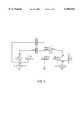
- FIG. 1shows a PAN transmitter communicating with a PAN receiver. Both devices are battery powered, electrically isolated, and have a pair of electrodes.
- the PAN transmittercapacitively couples a modulating picoamp displacement current through the human body to the receiver.
- the return pathis provided by the earth ground, which includes all conductors and dielectrics in the environment that are in close proximity to the PAN devices.
- the earth groundneeds to be electrically isolated from the body to prevent shorting of the communication circuit.
- the PAN transmitteris modeled as an oscillator, and the receiver is modeled as a differential amplifier.
- the basic principle of a PAN communication channelis to break the impedance symmetry between the transmitter electrodes and receiver electrodes.
- the transmitter's and receiver's intraelectrode impedancesare ignored since the former is a load on an ideal voltage source and the latter is modeled as an open circuit.
- the four remaining impedancesare labeled A, B, C, and D.
- the circuitis rearranged to show how PAN device communication works by breaking the symmetry between the four electrodes.
- FIG. 3illustrates an electric field model of a PAN transmitter T communicating with a PAN receiver R. A small portion of the electric field G reaches the receiver R.
- the transmitter T electrode closest to the body tbhas a lower impedance to the body than the electrode facing toward the environment te. This enables the transmitter T to impose an oscillating potential on the body, relative to the earth ground, causing electric fields A, B, C, D, and E.
- the impedance asymmetry of the receiver electrodes (rb and re) to the body and environmentallow the displacement current from electric fields F and G to be detected. Since the impedance between the receiver electrodes is nonzero, a small electric field H exists between them.
- the electric fields modelis used to produce the electric circuit shown in FIG. 4. Some typical component values are shown for watch-based PAN devices.
- the transmitter Tcapacitively couples to receiver R through the body (modeled as a perfect conductor).
- the earth groundprovides the return signal.
- the circuitreveals that body capacitance to the environment E degrades PAN communication by grounding the potential that the transmitter T is trying to impose on the body.
- the circuit modelalso suggests that feet are the best location for PAN devices, providing large electrodes in close proximity to the body and environment, respectively. This is particularly true for the environment electrode (te or re), which is the weakest link (largest impedance) in the circuit.
- the locationalso suggests a novel power source, i.e. PAN devices embedded in shoe inserts that extract power from walking. An adult dissipates several hundred milliwatts while walking. A piezoceramic pile charging a capacitor at an efficiency as low as 10 percent can provide enough power for a PAN device.
- PAN devicescan take the shape of commonly worn objects, such as watches, credit cards, eyeglasses, identification badges, belts, waist packs, and shoe inserts.
- Head-mounted PAN devicescan include headphones, hearing aids, microphones, and head-mounted displays.
- Shirt pocket PAN devicesmay serve as identification badges.
- the wristwatchis a natural location for a display, microphone, camera, and speaker.
- a waist pouchcan carry a PDA, cellular phone, keypad, or other devices that are large and heavy.
- PAN devices incorporating sensorscan provide medical monitoring for such bodily functions as heartbeat, blood pressure, and respiratory rate.
- Pants pocketsare a natural location for wallet-based PAN devices to store information and identify the possessor.
- Shoe insertscan be self-powered and provide a data link to remote PAN devices located in the environment, such as workstations and floor transponders that detect the location and identity of people.
- a PAN prototypewas developed to demonstrate the digital exchange of data through a human body using battery-powered low-cost electronic circuitry.
- the detectorsynchronously integrates the tiny received displacement current (e.g., 50 picoamperes, 330 KHz) into a voltage that can be measured by a slow, low-resolution analog-to-digital converter (50 KHz, 8 bits) provided by the microcontroller.
- the PAN transceiveruses five off-the-shelf components.
- the analog components and microcontrollercan be combined into a single CMOS (complementary metal-oxide semiconductor) integrated circuit to produce a low-cost integrated PAN transceiver.
- CMOScomplementary metal-oxide semiconductor
- the resonant tank circuitproduces a clean sine wave output from a square wave input, minimizing RF harmonics, and boosts the output voltage in proportion to the Q of the tank.
- the transmit voltagecan also be digitally programmed by varying the pulse width of the driving square wave.
- the integratoris discharged after every message bit (integrate-and-dump filtering) to minimize intersymbol interference.
- On-off keyingturns the carrier on to represent a message bit one and turns the carrier off for a message bit zero.
- the signal-to-noise performanceis improved by increasing the transmit voltage.
- Direct sequence spread spectrummodulates the carrier with a pseudonoise (PN) sequence, producing a broadband transmission much greater than the message bandwidth.
- PNpseudonoise
- Symbol-synchronous PN modulationis used where a message bit one is represented by transmitting the entire PN sequence, and a message bit zero is represented by transmitting the inverted PN sequence.
- the signal-to-noise performanceincreases with the length of the PN sequence.
- the prototype hardwarewas capable of detecting either on-off keying or direct sequence spread spectrum, determined by microcontroller coding.
- on-off keyingthe bipolar chopper switches are driven at the carrier frequency, and the integrated result is compared to a fixed threshold to determine the value of the message bit.
- Quadrature detectionis implemented by performing two sequential integrations, at 0 and 90 degrees phase, for each message bit.
- the switchesare driven by the PN sequence, and the integrated result, which is the correlation, is compared to two thresholds. If the correlation is greater than a positive threshold, the message bit is one. If the correlation is less than a negative threshold, the message bit is zero. If the correlation is between these thresholds (the dead zone), no message bit is received.
- the microcontrollertransmits the message to a host computer over an optical link (not shown), which electrically isolates the transceiver allowing evaluation and debugging independent of an electrical ground reference.
- the demonstration prototype of the PAN systemconsisted of a battery-powered transmitter and receiver, and a host computer running a terminal program.
- the PAN prototypesmeasure 8 ⁇ 5 ⁇ 1 centimeters, about the size of a thick credit card.
- the transmittercontains a microcontroller that continuously transmits stored ASCII characters representing an electronic business card.
- the devicesare located near the feet, simulating PAN shoe inserts. When the persons communicating are in close proximity, particularly when they shake hands, an electric circuit is completed, allowing picoamp signals to pass from the transmitter through one body, to the other body, to the receiver, and back through the earth ground.
- ASCII charactersare sent to the receiver, demodulated, and sent via serial link to the host computer where they are displayed. Thus, when the subjects shake hands, one downloads his or her electronic business card to the other.
- PANpersonal area network
- Available publications regarding the developmentsuggest a number of areas of potential application. Among these is the automation and securing of consumer business transactions.
- One suggestionis a public phone equipped with PAN sensors which could automatically identify the user, who would no longer have to input calling card numbers and PINs. It is stated that this application would significantly reduce fraud and make calling easier and more convenient for users.
- the present inventionaddresses the above noted limitations and provides advances over existing technology and over the published suggestions for application of the personal area network development.
- the inventionfurther provides multiple arrangements whereby PAN devices enable new personalized and other advanced telecommunication services.
- these new proceduresare further enhanced by the subscriber carrying a PAN device which stores therein the profile and other data relating to the subscriber.
- This profile and dataare then utilized by the subscriber to initiate personalized telephone services at any PAN equipped telephone. Positive subscriber identification is virtually assured.
- the telephone servicesare implemented largely through local plant or equipment, i.e. the local switching system environment.
- such a roaming subscribermay obtain the personalized service to which he subscribes by downloading his profile and any necessary related data by body contact or other proximity coupling to a sensor provided at public telephones such as pay phones.
- these telephonesneed not be of a particular type inasmuch as the necessary processes are performed by the local equipment, plant, or switching system environment to which that telephone is connected.
- This featurepermits the new service to be provided without regard to the fact that the toll telephones in the area may be owned by various entities and may constitute instruments of varying types and capabilities.
- the near field sensing and detecting deviceneed not be provided as an integral part of a telephone or other terminal but may be separately mounted. In this manner it is unnecessary to make any change to the terminal itself.
- Another feature of the inventionprovides positive authentication of the person utilizing the PAN device.
- This embodimentobviates the ambiguity presented where the PAN device falls into the possession of persons other than the user, and provides a significantly higher degree of fraud protection.
- This identificationis preferably implemented through the use of voice authentication.
- Appropriate voice templates of the subscriberare stored in the PAN device and downloaded into the local telephone network through any PAN equipped telephone. The downloaded templates are then processed in the local telephone network to identify the person in possession of the PAN device. In this manner it is possible to virtually eliminate the problem of the PAN device being fraudulently used by one other than the person who created the templates.
- the inventionincludes a methodology wherein a subscriber bearing a near field electric electrostatic field generating and receiving device approaches a stationary near field electric field receiving device which is connected to a communications network so as to establish a coupling between the near field devices. When this coupling is established there is a transfer of data signals and an identification of one or more biometric characteristics of the subscriber.
- the inventionfurther provides a subscriber borne and coupled transceiver generating and receiving near-field electric field signals and having data storage and a stationary transceiver generating and receiving near-field electric field signals and having data storage and coupled to a link to a switching system switching system in a telecommunication network, wherein the subscriber borne transceiver has stored therein data characterizing the identity of the subscriber, and the network contains control processors which respond to the subscriber coupling the transceivers together through currents carried by the body of said person to identify the subscriber.
- FIG. 1shows a diagrammatic depiction of a PAN transmitter communicating with a PAN receiver.
- FIG. 2depicts the circuitry rearranged to show how the PAN device communication works by breaking the symmetry between the four electrodes.
- FIG. 3illustrates the electrical field paths in the system.
- FIG. 4shows the electrical circuitry of the PAN system.
- FIG. 5shows further details of the circuitry.
- FIG. 6shows a skeletal line depiction of a public toll or pay telephone booth with a customer or subscriber using the coin telephone.
- FIG. 7is a simplified block diagram of an intelligent telephone network that may be used to offer advanced personalized telephone service.
- FIG. 8is a simplified block diagram illustrating the significant functional components of an SSP type central office switching system used in the network of FIG. 7.
- FIG. 9is a simplified block diagram illustrating the significant functional components of an Intelligent Peripheral (IP) used in the network of FIG. 7.
- IPIntelligent Peripheral
- FIG. 6there is shown a skeletal line depiction of a toll or pay telephone booth 10 housing a coin telephone 12 having a handset 14 coin slot 16, and coin return 18.
- a subscriber 20is shown equipped with a wrist watch version 22 of a PAN device of the type described in detail in the IBM Systems Journal publication referenced and discussed hereinabove.
- the subscriberis shown touching a sensor 24 which serves as the "antenna" of a PAN transceiver unit housed within the telephone 12.
- the transceiver unitis also of the same type as described in detail in the IBM Systems Journal publication. As previously stated, that publication is incorporated by reference herein in its entirety.
- the transceiver unit in the wrist watch PAN deviceproduces a modulated signal that is detected and demodulated by the companion transceiver within the telephone housing, as described hereinabove.
- the subscriber worn or carried PAN unitis here shown and discussed as a wrist watch unit, it is to be understood that other versions of such a transceiver may be utilized as previously discussed. Thus other possible versions may be provided in the form of a wallet or a self powered shoe mounted insert. Other varieties of PAN transceivers are discussed hereinabove.
- the transceiver in the telephone boothis shown as incorporated in the telephone terminal in FIG. 6, the preferred embodiment utilizes a separate transceiver mounted within the booth so as to be available to potential users. Such a separate mounted transceiver is shown diagrammatically at 26 connected to the telephone terminal by a suitable data link 28.
- FIG. 6shows the subscriber lifting the telephone handset 14 to create an off-hook condition, as presently discussed.
- the preferred implementations of the present inventionare applied in a communication network comprising an intelligent implementation of a public switched telephone network.
- the preferred networkincludes a number of central office switches interconnected by trunk circuits and servicing a substantial number of telephone links.
- the intelligent networkalso includes a service control point storing a database of records used in controlling services provided through the central offices.
- a first signaling networkcarries signaling messages between the offices as well as signaling messages between the offices and the service control point.
- a multifunction intelligent peripheralis provided and also may exchange signaling information with the service control point, preferably over a second signaling network.
- the preferred networkincludes a central office switching system capable of processing a call using profile information selected in response to a virtual equipment number.
- An office equipment or OE numberis ⁇ virtual ⁇ where it is assigned to an individual subscriber, instead of to specific network equipment such as a line termination or a specific station.
- the switching systemincludes interface modules coupled to the communication links and a switch providing selective communication connections between the interface modules.
- An administrative modulecontrols connections provided by the switch.
- the administrative moduleincludes mass storage containing subscriber profiles, a processor for providing control instructions to the switch, and a signaling interface for signaling communication with at least one external network node.
- the processorretrieves a subscriber profile corresponding to the virtual office equipment number from the mass storage. The processor uses the retrieved profile to process a selective connection through the switch between two of the interface modules.
- the personalized service of the present inventionIn response to each of several types of service requests, the personalized service of the present invention initially identifies the individual subscriber or user, preferably using a speaker identification/verification procedure. While speaker identification is preferred it is to be understood that other biometric characteristics of the user, such as finger or hand prints may be used.
- the systemretrieves profile information corresponding to the identified subscriber or user.
- the communication networkprocesses one or more calls to or from an identified communication link using the individual user's profile data.
- the service requestOn an outgoing telephone call from the subscriber or user, for example, the service request may be an off-hook signal, and the network may provide ⁇ dial-tone ⁇ type telephone services based on the retrieved profile information. In this example, the network may provide a dial tone signal or a customized prompt and then permit the caller to out-dial a call. Caller identification, calling features and/or additional identification of the responding party functions apply based on the profile information.
- FIG. 7provides a simplified illustration of a preferred intelligent telephone network for implementing the personal dial tone service in accord with the present invention.
- the telephone networkincludes a switched traffic network and a common channel signaling network carrying the control signaling messages for the switched telephone traffic network.
- the systemfurther includes a secondary signaling network.
- the telephone or traffic network(operated by a combination of local carriers and interexchange carriers) includes a number of end office and tandem office type central office switching systems 11.
- FIG. 7shows a number of subscriber stations, depicted as telephones 1, connected to a series of central office switches 11 1 to 11 N .
- the connections to the central office switches 11utilize telephone lines, and the switches are telephone type switches for providing landline communication.
- Trunk circuits TRcarry communication traffic between the central office switches 11.
- Each end office type central office switchsuch as 11 and 11 N , provides switched telephone connections to and from local communication lines or other subscriber links coupled to end users stations or telephone sets 1.
- the central office 11 1serves as an end office to provide switched telephone connections to and from local communication lines coupled to end users telephone station sets, such as telephone 1 A
- the central office 11 Nserves as an end office to provide switched telephone connections to and from local communication lines coupled to end users telephone station sets, such as telephone 1 B .
- the typical telephone networkalso includes one or more tandem switching offices such as office 11 T , providing trunk connections between end offices.
- the traffic networkconsists of local communication links and a series of switching offices interconnected by voice grade trunks, only two examples of which are shown at TR in FIG. 6.
- One set of trunks TRmight interconnect the first end office 11 1 to the tandem office 11 T
- another set of trunks TRmight interconnect the tandem office 11 T to another end office 11 N .
- Other trunksmight directly connect end offices.
- many officesserve as both end offices and tandem offices for providing different call connections.
- FIG. 7shows connections to the stations 1 via lines, and typically these links are telephone lines (e.g. POTS or ISDN). It will be apparent to those skilled in the art, however, that these links may be other types of communication links, such as wireless links.
- the stationshave caller ID capability. If the line is an ISDN line, the station may incorporate a display for visually presenting the caller ID information and other signaling related messages. If the link is a typical analog telephone line, the customer premises equipment includes a caller ID terminal, one example of which is shown at 5 B .
- the terminal 5 Bdisplays at least telephone numbers and preferably displays alphanumeric information to enable displays of callers names.
- the terminal devices or stations 1can comprise any communication device compatible with the local communication link.
- the linkis a standard voice grade telephone line, for example, the terminals could include facsimile devices, modems etc.
- the processing in accord with the inventionrelies on identification of the subscriber, preferably by voice based recognition.
- the terminalspreferably include two-way voice communication elements.
- the lines and trunks through the central offices 11carry the communication traffic of the telephone network.
- the preferred telephone networkalso includes a common channel interoffice signaling (CCIS) network carrying a variety of signaling messages, principally relating to control of processing of calls through the traffic portion of the network.
- CCIS networkincludes packet data links (shown as dotted lines) connected to appropriately equipped central office switching systems such as offices 11 and a plurality of packet switches, termed Signaling Transfer Points (STPs) 15. To provide redundancy and thus a high degree of reliability, the STPs 15 typically are implemented as mated pairs of STPs.
- the CCIS network of the telephone systemoperates in accord with an accepted signaling protocol standard, preferably Signaling System 7 (SS7).
- SS7Signaling System 7
- each central office 11has at least minimal SS7 signaling capability, which is conventionally referred to as a signaling point (SP) in reference to the SS7 network.
- SPsignaling point
- the officescan exchanges messages relating to call set-up and tear-down, typically in ISDN-UP format.
- At least some, and preferably all, of the central office switches 11are programmed to recognize identified events or points in call (PICs) as advanced intelligent network (AIN) type service triggers.
- PICsidentified events or points in call
- AINadvanced intelligent network
- a central office 11initiates a query through the CCIS signaling network to a control node to either a Service Control Point (SCP) 19 or to a database system, such as a Line Identification Database (LIDB) 21.
- SCPService Control Point
- LIDBLine Identification Database
- the SCP 19provides instructions relating to AIN type services.
- the LIDB 21provides subscriber account related information, for calling card billing services or for subscriber name display purposes in an enhanced caller ID application.
- SSPsService Switching Points
- the central office switches 11typically consist of programmable digital switches with CCIS communications capabilities.
- a switchis a 5ESS type switch manufactured by AT&T; but other vendors, such as Northern Telecom and Seimens, manufacture comparable digital switches which could serve as the SSPs and SPs.
- the SSP type implementation of such switchesdiffers from the SP type implementation of such switches in that the SSP switch includes additional software to recognize the full set of AIN triggers and launch appropriate queries.
- a specific example of an SSP capable switchis discussed in detail later, with regard to FIG. 8.
- the program controlled switchaccepts instructions to load profiles and/or receives profiles over a signaling link.
- these profilesare identified by virtual office equipment numbers.
- the profilesinclude a range of information relating to subscribers services, such as service features, classes of service, individual billing options, and according to a preferred feature of the invention, information relating to restrictions applied to individual users, as well as the performance of functions related to that user.
- the above described data signaling network between the SSP type central offices 11 and the SCP 19is preferred, but other signaling networks could be used.
- a number of central office switches, an SCP and any other signaling nodescould be linked for data communication by a token ring network.
- the SSP capabilitymay not always be available at the local office level, and several other implementations might be used to provide the requisite SSP capability.
- none of the end office switchesmay have SSP functionality. Instead, each end office would connect through a trunk to a tandem office which has the SSP capability.
- the SSP tandemthen communicates with the SCP via an SS7 type CCIS link, as in the implementation described above.
- the SSP capable tandem switchesare digital switches, such as the 5ESS switch from AT&T; and the non-SSP type end offices might be 1A analog type switches.
- the SCP 19may be a general purpose computer storing a database of call processing information.
- the SCP 19actually is an Integrated Service Control Point (ISCP) developed by Bell Atlantic and Bell Communications Research.
- the ISCPis an integrated system.
- the ISCPincludes a Service Management System (SMS), a Data and Reporting System (DRS) and the actual database also referred to as a Service Control Point (SCP).
- SCPmaintains a Multi-Services Application Platform (MSAP) database which contains call processing records (CPRs) for processing of calls to and from various subscribers.
- MSAPMulti-Services Application Platform
- the ISCPalso typically includes a terminal subsystem referred to as a Service Creation Environment or SCE for programming the MSAP database in the SCP for the services subscribed to by each individual customer.
- SCEService Creation Environment
- the components of the ISCPare connected by an internal, high-speed data network, such as a token ring network.
- the internal data networkalso typically connects to a number of interfaces for communication with external data systems, e.g. for provisioning and maintenance.
- one of these interfacesprovides communications to and from the SCP 19 via a packet switched data network, such as the TCP/IP network 27.
- the SCPmay be implemented in a variety of other ways.
- the SCPmay be a general purpose computer running a database application and may be associated with one of the switches.
- Another alternativeis to implement a database of CPRs or the like within an STP (see e.g. Farris et al. U.S. Pat. No. 5,586,177).
- the LIDB database 21is a general purpose computer system having a signaling link interface or connection to a pair of STPs 15.
- the computerruns a database program to maintain a database of information relating to customer accounts and identifications.
- a subscriber's entry in the LIDB databasemight include the subscriber's telephone number, a personal identification number for credit card billing purposes, and the subscriber's name and address.
- the preferred telephone networkalso includes one or more intelligent peripherals (IPs) 23 to provide enhanced announcement and digit collection capabilities and speech recognition.
- IPsintelligent peripherals
- the IP 23is essentially similar to that disclosed in commonly assigned U.S. Pat. No. 5,572,583 to Wheeler, Jr. et al. entitled “Advanced Intelligent Network with Intelligent Peripherals Interfaced to the Integrated Services Control Point,” and the disclosure of the network and operation of the IP disclosed from that Patent is incorporated herein in its entirety by reference.
- the IP 23may connect to one or more central offices 11.
- the connectionstransport both communication traffic and signaling.
- the connection between a central office 11 and the IP 23may use a combination of a T1 and a Simplified Message Desk Interface (SMDI) link, but preferably this connection utilizes a primary rate interface (PRI) type ISDN link.
- SMDISimplified Message Desk Interface
- PRIprimary rate interface
- Each such connectionprovides digital transport for a number of two-way voice grade type telephone communications and a channel transporting signaling data messages in both directions between the switch and the IP.
- the SCP 19communicates with the IP 23. These communications could utilize an 1129 protocol and go through an SSP type central office 11 and the SS7 network. However, in the preferred embodiment of FIG. 6, the IP 23 and the SCP 19 communicate with each other via a separate second signaling network 27. These communications through network 27 between the IP and the SCP may utilize an 1129+ protocol or a generic data interface (GDI) protocol as discussed in the above incorporated Patent to Wheeler, Jr. et al.
- GDIgeneric data interface
- the IP 23can provide a wide range of call processing functions, such as message playback and digit collection.
- the IPalso performs speaker identification/verification (SIV) on audio signals received from users.
- the IP 23 used for the personalized serviceincludes a voice authentication module to perform the necessary speaker identification/verification function.
- the IP 23also includes storage for subscriber specific template or voice feature information, for use in identifying and authenticating subscribers based on speech.
- the IP 23 serving a subscriber's local areastores the templates and performs the speaker identification/verification.
- the templatesmay be transferred between SCP/IP pairs, to allow an IP near a subscriber's current location to perform the speaker identification/verification on a particular call. For example, if a remote IP 23 R required a template for a subscriber from the region served by the IP 23, the remote IP 23 R would transmit a template request message through the network 27 to the IP 23. The IP 23 would transmit the requested template back through the network 27 to the remote IP 23 R .
- the PAN device carried by the subscriberhas loaded and stored therein the subscriber specific template or voice feature (or other biometric) information, for use in identifying and authenticating subscribers based on speech.
- the initial identification of the credit card number and PIN via the PAN deviceestablishes a two way connection with the local link to the telephone with which the PAN device is associated. Following establishment of that connection the credit card number, PIN, customer or subscriber profile, voice mail interface, and voice templates are transferred to storage in the switching system environment in the local switched network.
- the profile and voice templatesthus are immediately available in the local network for loading into the switch and the IP which handles voice authentication for that network. Voice authentication may then be effected and the caller may proceed with the call.
- routingtypically is based on dialed digit information, profile information regarding the link or station used by the calling party, and profile information regarding a line or station in some way associated with the dialed digits.
- Each exchangeis identified by one or more three digit codes. Each such code corresponds to the NXX digits of an NXX-XXX (seven digit) telephone number or the three digits following the area code digits (NPA) in a ten-digit telephone number.
- NPAarea code digits
- the telephone companyalso assigns a telephone number to each subscriber line connected to each switch. The assigned telephone number includes the area code and exchange code for the serving central office and four unique digits.
- OEoffice equipment
- a subscriber's linemight terminate on a pair of terminals on the main distribution frame of a switch 11.
- the switchidentifies the terminals, and therefore the particular line, by an OE number assigned to that terminal pair.
- the operating companymay assign different telephone numbers to the one line at the same or different times. For example, a local carrier may change the telephone number because a subscriber sells a house and a new subscriber moves in and receives a new number.
- the OE number for the terminals and thus the line itselfremains the same.
- an end office type switchOn a normal call, an end office type switch will detect an off-hook condition on the line and provide dial tone. The switch identifies the line by its OE number. The office also retrieves profile information corresponding to the OE number and off-hook line. If needed, the profile identifies the currently assigned telephone number. The switch in the end office receives dialed digits and routes the call. The switch may route the call to another line serviced by that switch, or the switch may route the call over trunks and possibly through one or more tandem offices to an office that serves the called party's station or line. The switch terminating a call to a destination will also utilize profile information relating to the destination, for example to forward the call if appropriate, to apply distinctive ringing, etc.
- AIN call processinginvolves a query and response procedure between an SSP capable switching office 11 and a database system, such as the SCP 19.
- the SSP capable switching officesinitiate such processing upon detection of triggering events.
- a central office switching system 11will recognize an event in call processing as a ⁇ Point in Call ⁇ (PIC) which triggers a query to the SCP 19.
- PIC⁇ Point in Call ⁇
- the SCP 19will return an instruction to the switching system 11 to continue call processing.
- PIC⁇ Point in Call ⁇
- This type of AIN call processingcan utilize a variety of different types of triggers to cause the SSPs 11 to initiate the query and response signaling procedures with the SCP 19.
- the personal dial tone serviceutilizes an off-hook immediate trigger, a dialed number trigger and a terminating attempt trigger (TAT), to facilitate different aspects of the service.
- TATterminating attempt trigger
- the SSP central office 11that is serving an outgoing call extends the call to the IP 23 providing the speaker identification/verification (SIV) functionality.
- this operationinvolves AIN type call routing to the IP.
- the IP 23prompts the caller and collects identifying information, preferably in the form of speech.
- the IPanalyzes the caller's input to identify the caller as a particular subscriber. If successful, the IP signals the SSP to load profile data for that subscriber into the register assigned to the call in the call store. In most of the preferred service applications, the IP disconnects, and the SSP central office 11 processes the call in accord with the loaded profile information.
- the central office 11may now provide actual dial tone or provide a message prompting the caller to dial a destination number.
- the callerdials digits, and the central office processes the digits to provide the desired outgoing call service, in the normal manner.
- the IPmay stay on the line, to monitor speech and thus caller identity, for some service applications.
- the call processing by the central office switch 11utilizes the loaded subscriber profile information.
- the profile datamay indicate specific procedures for billing the call to this subscriber on some account not specifically linked to the originating telephone station or line.
- the SSP central office 11before providing dial-tone service, the SSP central office 11 that is serving an outgoing call extends the call to the IP 23 and downloads the specific templates from the PAN device for providing the speaker identification/verification (SIV) functionality.
- this operationinvolves AIN type call routing to the IP.
- the IP 23prompts the caller and collects identifying information, preferably in the form of speech. This may constitute the caller speaking his full name.
- the IPanalyzes the caller's input to identify the caller as a particular subscriber using the downloaded templates. If successful, the IP signals the SSP to load profile data for that subscriber into the register assigned to the call in the call store.
- the SSPloads that profile data from the PAN unit (with or without buffering).
- the IPdisconnects, and the SSP central office 11 processes the call in accord with the loaded profile information.
- the central office 11may now provide actual dial tone or provide a message prompting the caller to dial a destination number.
- the callerdials digits, and the central office processes the digits to provide the desired outgoing call service, in the normal manner.
- the call processing by the central office switch 11utilizes the loaded subscriber profile information which may be identified by a virtual OE number.
- the profile datamay indicate specific procedures for billing the call to this subscriber on some account not specifically linked to the originating telephone station or line. This is particularly true with respect to public telephones such as pay phones.
- this systemprovides call processing by equipment in the local switching environment.
- Selected subscriber profile informationmay also be used on incoming calls.
- a serving central office SSP 11detects a call to a line having the personalized service, processing hits a terminating attempt trigger (TAT).
- TATterminating attempt trigger
- the SSPinteracts with the SCP 19 and routes the call to the IP 23.
- the IP 23prompts the caller to identify a desired called party. Menu announcement together with either digit collection or preferably speech recognition processing by the IP 23 facilitates identification of the desired called party from those associated with the line.
- the IP 23Based on identification of the called subscriber, the IP 23 signals the SSP switch 11 to load profile data for that subscriber into the register assigned to the call in the call store. In this case, however, the switch 11 uses selectively loaded profile information for terminating the call.
- the IPdisconnects, and the SSP central office 11 processes the call in accord with the loaded profile information.
- the central office 11may provide a distinctive ringing signal corresponding to the identified subscriber.
- This serviceenables distinctive ringing for multiple subscribers on one line without assigning each subscriber a separate telephone number.
- the loaded profile informationmay specify call forwarding in event of a busy or no-answer condition. This enables routing of the call to the identified subscriber's mailbox, or another alternate destination selected by the subscriber, even though the call did not utilize a unique telephone number uniquely assigned to the called subscriber.
- the present inventionencompasses a procedure in which a subscriber calls in from a line not specifically designated for personal dial tone service, such as, for example, a public telephone.
- the networkroutes the call to the IP 23, and the IP identifies the subscriber and the line from which the subscriber called-in.
- the subscribercan interact with the IP 23 to have his or her personal dial tone service associated with that line, either for one call or for some selected period of time.
- the IP 23instructs the appropriate central office switch(es) 11 to load profile data associated with the subscriber.
- the IP 23might instruct the end office switch to load the profile data only in the assigned call store register.
- the switchwould use the profile data only for a single call, for example to bill a call from a pay-phone or a hotel room telephone to the subscriber's home account. This procedure is utilized for a PAN call as above discussed.
- the IP 23might instruct the central office 11 serving the line to the calling station 1 to utilize a virtual office equipment number (OE) and associated profile data for calls to and from that line for some period of time.
- OEvirtual office equipment number
- the IP 23would also instruct the central office 11 serving the line to the subscriber's home station 1 to modify the subscriber's profile to forward calls for the subscriber's telephone number.
- the modified profile data in the home office 11would result in forwarding of the subscriber's incoming calls through the office 11 to the selected station 1, for the set period of time.
- the present inventionrelies on the programmable functionality of the central office switches and the enhanced call processing functionalities offered by the IPs. To understand these various functionalities, it may be helpful to review the structure and operation of a program controlled central office and one implementation of an IP. Subsequent description will explain several of the above outlined call processing examples in greater detail.
- FIG. 8is a simplified block diagram of an electronic program controlled switch which may be used as any one of the SSP type central offices 11 in the system of FIG. 6.
- the switchincludes a number of different types of modules.
- the illustrated switchincludes interface modules 51 (only two of which are shown), a communications module 53 and an administrative module 55.
- the interface modules 51each include a number of interface units 0 to n.
- the interface unitsterminate lines from subscribers' stations, trunks, T1 carrier facilities, etc. Each such termination is identified by an OE number. Where the interfaced circuit is analog, for example a subscriber loop, the interface unit will provide analog to digital conversion and digital to analog conversion. Alternatively, the lines or trunks may use digital protocols such as T1 or ISDN.
- Each interface module 51also includes a digital service unit (not shown) which is used to generate call progress tones and receive and detect dialed digits in pulse code or dual-tone multifrequency form.
- the unit 0 of the interface module 51'provides an interface for the signaling and communication links to the IP 23.
- the linkspreferably consist of one or more ISDN PRI circuits each of which carries 23 bearer (B) channels for communication traffic and one data (D) channel for signaling data.
- Each interface module 51includes, in addition to the noted interface units, a duplex microprocessor based module controller and a duplex time slot interchange, referred to as a TSI in the drawing.
- Digital words representative of voice informationare transferred in two directions between interface units via the time slot interchange (intramodule call connections) or transmitted in two directions through the network control and timing links to the time multiplexed switch 57 and thence to another interface module (intermodule call connection).
- the communication module 53includes the time multiplexed switch 57 and a message switch 59.
- the time multiplexed switch 57provides time division transfer of digital voice data packets between voice channels of the interface modules 51 and transfers signaling data messages between the interface modules.
- the switch 57 together with the TSIs of the interface modulesform the overall switch fabric for selectively connecting the interface units in call connections.
- the message switch 59interfaces the administrative module 55 to the time multiplexed switch 57, so as to provide a route through the time multiplexed switch permitting two-way transfer of control related messages between the interface modules 51 and the administrative module 55.
- the message switch 59terminates special data links, for example a link for receiving a synchronization carrier used to maintain digital synchronism.
- the administrative module 55provides high level control of all call processing operations of the switch 11.
- the administrative module 55includes an administrative module processor 61, which is a computer equipped with disc storage 63, for overall control of CO operations.
- the administrative module processor 61communicates with the interface modules 51 through the communication module 55.
- the administrative module 55may include one or more input/output processors (not shown) providing interfaces to terminal devices for technicians and data links to operations systems for traffic, billing, maintenance data, etc.
- a CCIS terminal 73 and an associated data unit 71provide an SS7 signaling link between the administrative module processor 61 and one of the STPs 15 (see FIG. 6). Although only one such link is shown, preferably there are a plurality of such links providing redundant connections to both STPs of a mated pair and providing sufficient capacity to carry all necessary signaling to and from the particular office 11.
- the SS7 signaling through the terminal 73, the data unit 71 and the STPsprovides two-way signaling data transport for call set-up related messages to and from other offices. These call set-up related messages typically utilize the ISDN-UP (ISDN-users part) protocol portion of SS7.
- the SS7 signaling through the terminal 73, the data unit 71 and the STPsalso provides two-way signaling data transport for communications between the office 11 and database systems or the like, such as the SCP 19.
- the communications between the office 11 and the database systems or the likeutilize the TCAP (transactions capabilities applications part) protocol portion of SS7.
- the administrative module 55also includes a call store 67 and a program store 69. Although shown as separate elements for convenience, these are typically implemented as memory elements within the computer serving as the administrative module processor 61.
- the program store 69stores program instructions which direct operations of the computer serving as the administrative module processor 61.
- a register assigned within the call store 67stores translation and user profile information retrieved from disc storage 63 together with routing information and any temporary information needed for processing the call. For example, for a residential customer initiating a call, the call store 67 would receive and store line identification and outgoing call billing information corresponding to an off-hook line initiating a call. For the personal dial-tone service, the assigned register in the call store 67 will receive and store different profile data depending on the particular subscriber associated with any given call. A register in the call store is assigned and receives profile data from the disc memory both for originating subscribers on outgoing calls and for terminating subscribers on incoming calls.
- FIG. 9is a functional diagram illustration of an IP 23 for performing the subscriber identification functions, possibly by dialed digit input and preferably by analysis and recognition of speech.
- the preferred IP architectureutilizes separate modules for different types of services or functions, for example, one or two Direct Talk type voice server modules 231A, 231B for interfacing ISDN PRI trunks to the SSP central office(s) 11. Separate modules 233, 235 perform voice authentication and speech recognition.
- the IP 23includes a variety of additional modules for specific types of services, such as a server module 237 for fax mail, and another server 239 for voice mail services.
- the various modulescommunicate with one another via an internal data communication system or bus 240, which may be an Ethernet type local area network.
- Each Direct Talk module 231A or 231Bcomprises a general purpose computer, such as an IBM RS-6000, having digital voice processing cards for sending and receiving speech and other audio frequency signals, such as IBM D-talk 600 cards. Each voice processing card connects to a voice server card which provides the actual interface to T1 or primary rate interface ISDN trunks to the switching office.
- the Direct Talk computeralso includes a signaling card, providing two-way signaling communication over the D-channel of the PRI link.
- Each Direct Talk computeralso includes an interface card for providing two-way communications over the internal data communications system 240.
- the voice processing cards in the Direct Talk modules 231A, 231Bprovide voice message transmission and dialed digit collection capabilities.
- the modules 231A, 231Balso perform the necessary line interface functions for communications to and from those servers which do not incorporate actual line interfaces.
- a Direct Talk module 231 connected to a callwould demodulate incoming data and convert the data to a digital format compatible with the internal data communication network 240. The data would then be transferred over network 240 to the fax server 237.
- the server 237would transfer the data to one of the Direct Talk modules over the network 240.
- the Direct Talk module 231would reformat and/or modulate the data as appropriate for transmission over the ISDN link to the switch 11.
- the Direct Talk modulesprovide a similar interface function for the other servers, such as the voice mail server 239, the speech recognition module 235 and the voice authentication module 233.
- the Direct Talk moduleconnected to a call receives digital speech signals in the standard pulse code modulation format carried on a B-channel of an ISDN link.
- the Direct Talk modulereformats the speech data and transmits that data over the internal network 240 to the server or module performing the appropriate function, for example to the authentication module 233 for analysis and comparison of features to stored templates or feature data for known subscribers.
- the currently connected Direct Talk modulemay play an announcement from memory, e.g. to prompt a caller to say their name.
- the Direct Talk modulemay receive digitized speech over the network 240 from one of the other modules, such as a stored message retrieved from voice mail server 239.
- the Direct Talk modulereformats the speech signal as needed for transmission over the ISDN B-channel to the caller.
- the illustrated IPalso includes a communication server 243.
- the communication server 243connects between the data communication system 240 and a router 241, which provides communications access to the TCP/IP network 27 that serves as the second signaling communication system.
- the communication server 243controls communications between the modules within the IP 23 and the second signaling communication system.
- the server 243 and the router 241facilitate communication between the elements of the IP 23 and the SCP 19.
- the IPmay also use this communication system to communicate with other IP's, for example to send subscriber voice template information to the remote IP 23 R (FIG. 6) or to receive such information from that IP or some other network node.
- the personalized servicerelies on the voice authentication module 233 to perform the necessary speaker identification/verification function.
- the voice authentication module 233 within the IP 23stores a template or other feature or voice pattern information for each person who has the personalized service in the area that the IP services. For example, if the subscriber utilizes the personal dial tone service from a particular line, such as a shared line in a dormitory or the like, the IP stores the subscriber's voice pattern information in a file associated with the office equipment (OE) number of the particular line.
- OEoffice equipment
- the IP 23 serving a callmay obtain subscriber identification by dialed digit input and then obtain a copy of the template or feature data from a remote IP 23 R via communication through the TCP/IP network 27, in order to authenticate the subscriber's identity.
- the IPserving that subscriber and ⁇ train ⁇ that IP by speaking certain phrases. From the received audio signals representing those phrases, the IP would store templates or other pattern information for use in identifying and/or verifying that a caller is the particular subscriber.
- the voice authentication module 233receives speech information from the caller.
- the voice authentication module 233compares the received information to its stored template or feature data to identify a calling party as a particular subscriber.
- the IPis trained in a different manner.
- Current speech recognition technologypermits recognition with a reasonable degree of certitude based on training from a limited sample of recorded speech of a subject.
- recorded samples of prior telephone speechmay be used with available recognition facilities of a more sophisticated nature.
- the present inventionalso relies on the speech recognition capability of the module 235, particularly in processing of incoming calls in certain situations.
- the speech recognition module 235enables the IP to analyze incoming audio information to recognize vocabulary words.
- the IP 23interprets the spoken words and phrases to determine subsequent action. For example, the IP might recognize the caller speaking the name of a called subscriber and use the subscriber identification to instruct the terminating central office to control the call in accord with that subscriber's profile.
- the station 1 Ais a public station as shown in FIG. 7 and is equipped with a PAN transceiver connected to the local link serving the telephone.
- a handshake between the mobile and stationary unitsoccurs and the mobile unit transmits to the stationary unit a request to initiate a personal service PAN call.
- the mobile unittransmits initial subscriber identification, such as the home telephone number, virtual OE, credit card number, and PIN of the subscriber who owns or is the authorized possessor of the mobile PAN unit.
- the stationary PAN unittransmits this transferred information to the SSP to which the telephone station 1 A is connected.
- the person initiating the PAN callmay or may not have gone off-hook. While the telephone station in FIG. 6 is shown with a handset 14 the invention comprehends use of telephone stations which may not utilize a handset, such as speaker/microphone type stations.
- the PAN signalis utilized to initiate the call processing rather than the off hook signal.
- the PAN signalserves as a type of service request, i.e. a request to make an outgoing call.
- the serving central office 11 1detects this and commences its call processing. Specifically, the central office assigns a register in the call store 67 to this call and loads profile information associated with the service requesting line from the disc storage 63 into the assigned register.
- the central office 11 1is an SSP capable office, and the loaded profile data indicates an originating trigger set against the particular line.
- the originating triggermay be an off-hook immediate trigger or a trigger set against a data signal transmitted by the mobile PAN unit in its initial download of data to the stationary PAN unit.
- the serving SSP type office 11 1therefore detects this originating PIC as an AIN trigger.
- the SSP type central office switch 11 1launches a query to the SCP 19. Specifically, the SSP 11 1 creates a TCAP query message containing relevant information, such as the office equipment (OE) number assigned to the off-hook line, and identification of the mobile PAN unit and its request. This message is sent over an SS7 link to one of the STPs 15.
- the queryincludes a destination point code and/or a global title translation addressing the message to the SCP 19, and the STP 15 relays the query message over the appropriate link to the SCP 19.
- the query from the SSP central office 11 1identifies the caller's line by its associated office equipment (OE) number and possibly by a single telephone number associated with the line.
- the querymay also identify the virtual OE number of the subscriber which was transferred from the subscriber borne PAN unit.
- the SCP 19accesses its database, typically, the MSAP database set up in the ISCP, to determine how to process the particular call.
- the SCP 19identifies an access key in the query and uses the key to retrieve the appropriate record from the database.
- the queryindicates a PAN trigger as the trigger event, and therefore the SCP 19 uses the PAN trigger and the calling line office equipment (OE) number as the access key.
- the SCP 19retrieves from its database a call processing record and data relating to the handling of PAN requests.
- the particular retrieved processing record (CPR)corresponds to the office equipment (OE) number associated with the requesting line.
- the PAN datawill provide information necessary for routing the call to some node of the network that will perform speaker identification/verification (SIV).
- SIVis a function performed by an Intelligent Peripheral (IP), therefore the CPR provides information for routing the call to the nearest available IP having the SIV capability. Typically this will be found within the local environment of the switching system.
- IPIntelligent Peripheral
- the SCP 19formulates a response message instructing the SSP central office 11 1 serving the customer to route the call.
- the messageincludes information, e.g. a office equipment (OE) number or telephone number, used for routing a call to the identified IP 23.
- the SCP 19formulates a TCAP message in SS7 format, with the destination point code identifying the SSP office 11 1 .
- the SCP 19transmits the TCAP response message back over the SS7 link to the STP 15, and the STP 15 in turn routes the TCAP message to the SSP central office 11 1 .
- the TCAP messagealso includes instructions to the SSP to load the customer profile of the subscriber which corresponds to the subscriber's virtual OE number.
- the subscriber profile corresponding to the virtual OE numberwas initially downloaded from the subscriber borne PAN unit into the storage associated with the stationary PAN unit.
- the SSP type switch in the central office 11 1responds to the routing information by downloading the virtual OE profile from the stationary PAN store to the mass storage of the switching system, and connects the call to one of the lines or channels to the IP 23.
- a two-way voice grade call connectionnow extends between the calling station 1 A and the IP 23.
- the switchactually connects the calling line to the line to the IP before providing dial tone to the caller.
- the communication link to the IP 23provides both line connections and signaling, preferably over a primary rate interface (PRI) type ISDN link.
- PRIprimary rate interface
- the switch in that officealso provides call related data over the signaling link (D channel for ISDN).
- the call related datafor example, includes the office equipment (OE) number normally associated with the off-hook line and the virtual OE number of the calling subscriber. This identifies the profile which was transferred from the stationary PAN unit to the switching system storage.
- the IP 23In response to the incoming call, the IP 23 will seize the line, and it will launch its own query to the SCP 19.
- the IP 23 and the SCP 19communicate with each other via a separate second signaling network 27, for example utilizing either an 1129+ protocol or a generic data interface (GDI) protocol as discussed in U.S. Pat. No. 5,572,583 to Wheeler, Jr. et al.
- the query from the IP 23again identifies the caller's line by at least its associated office equipment (OE) number.
- the queryalso identifies the virtual OE number of the subscriber which was transferred from the subscriber borne PAN unit.
- the SCP 19again accesses the appropriate CPR and relevant PAN DATA, and provides a responsive instruction back through the network 27 to the IP 23.
- the SCPalso instructs the switching system to load the virtual OE profile from the switch mass storage into a call register, and instructs the IP to retrieve and load the speech templates corresponding to the virtual OE number.
- the IP 23could passively monitor any speech that the user might utter, the preferred implementation utilizes a ⁇ Challenge Phase ⁇ to prompt the user to input specific identifying information.
- the instructioncauses the IP 23 to provide a prompt message over the connection to the caller.
- the signal to the callermay be a standard dial tone or any other appropriate audio signal.
- the instruction from the SCP 19causes the IP 23 to provide an audio announcement prompting the caller to speak personal information.
- the IPplays an audio prompt message asking the caller, ⁇ Please say your full name ⁇ . The process may ask for any appropriate identifying information.
- the signal received by the IP 23goes over the lines and through the central office switch(es) for presentation via the telephone 1 A to the calling party.
- the callerwill speak identifying information into the microphone or handset, and the network will transport the audio signal to the IP 23.
- an IP 23can provide a wide range of call processing functions, such as message playback and digit collection.
- the IPalso performs speaker identification/verification (SIV) on the audio signal received from the off-hook telephone.
- SIVspeaker identification/verification
- the IP 23receives speech input information during actual call processing, for this service example, the IP analyzes the speech to extract certain characteristic information.
- the IP 23typically stores a template or other voice pattern information for each person who has the personalized service in the area that the IP normally services. If the IP 23 does not store the particular template or feature information it needs to process a call, the IP 23 can communicate with a remote IP 23 R to obtain that information.
- the SCPhas instructed the IP that the virtual OE number identifies a template which is stored in the stationary PAN storage or in storage in the switch.
- the IP 23communicates with the SSP to which it is connected and retrieve the template either from storage in the switch to which it has been downloaded by the stationary PAN or from the storage in the stationary PAN itself.
- the IP 23When the IP 23 receives input speech from the caller, and extracts the characteristic information during actual call processing, the IP compares the extracted speech information to stored pattern information in the template which it has retrieved, to identity and authenticate the particular caller.
- the voice authentication module 233 in the IP 23compares the extracted speech information to the template which was brought to it by the mobile PAN.
- the IP 23determines if the information extracted from the speech input matches the template data. If there is a match, the IP now knows the identity of the calling person. It is to be noted that this identification identifies both the mobile PAN and the person using the PAN unit. Based on the identification of the calling person and the virtual OE number supplied from the PAN, the IP 23 formulates a D-channel signaling message containing the virtual office equipment (OE) number together with an instruction to load that OE number into the register assigned to the call in place of the OE number of the off-hook line. The IP 23 supplies the message to the SSP central office switch 11 1 over the D-channel of the ISDN PRI link. In response, the administrative module processor 61 rewrites the OE number in the register assigned to the call using the OE number received from the IP 23.
- OEvirtual office equipment
- the administrative module processor 61 of central office switch 11 1Upon rewriting the OE number in the register, the administrative module processor 61 of central office switch 11 1 also reloads the profile information in the register. Specifically, the administrative module processor 61 retrieves profile information associated with the virtual office equipment (OE) number from the disc storage 63 into the register or from the stationary PAN if the profile was not previously downloaded. As such, the profile information in the assigned register in the call store 67 now corresponds to the identified caller, rather than to the off-hook line to the public station.
- OEvirtual office equipment
- the profile informationprovides a wide range of data relating to the caller's services.
- the profile dataprovides necessary billing information, enabling billing from the call to this particular caller.
- the profilealso defines various service features available to this subscriber on outgoing calls, such as three-way calling.
- the profilemay define a class of calling service available to the particular calling subscriber.
- the central office switch 11 1when the central office switch 11 1 reloads the profile, the central office disconnects the link to the IL 23 and connects tone receivers to the caller's line.
- the central office 11 1may provide a ⁇ dial tone ⁇ or other message over the line.
- the callernow dials digits in the normal manner, and the switch in the central office 11 1 loads the dialed digits into the assigned register within the call store 67.
- the central office 11 1utilizes the dialed digits and the subscriber's profile data to process the call. For example, if the dialed digits represent a call within the subscriber's permitted class of service, the switch completes the call to the destination station 1 B using the dialed digits in the normal manner. If the profile data requires a particular billing treatment, e.g. to bill a long distance call to the caller, the switch makes the appropriate record and forwards the record to the exchange carrier company's accounting office equipment.
- the networkprovides caller ID data naming the identified caller to a display at the destination station.
- Two processing methodologiesare envisioned for providing this calling subscriber ID feature.
- One methodinvolves accessing name information in a central database, such as LIDB, and the other method relies on name data from the PAN subscriber's profile. This latter method is preferred in that it is not dependent on the data involved in the local LIDB, which might not contain the desired information regarding this roaming subscriber.
- the networkperforms the steps of this process after identification of the subscriber, preferably based on speaker identification/verification (SIV).
- the IP 23supplies the signaling message containing the virtual office equipment (OE) number and the instruction to load that OE number into the assigned register to the SSP central office switch 11 1 over the D-channel of the ISDN PRI link.
- the administrative module processor 61rewrites the OE number in the register and reloads the PAN provided profile information in the register.
- the central office 11 1provides dial tone or the like over the line, the caller dials digits corresponding to the desired destination, and the switch in the central office 11 1 begins its processing to route the call through the network. Initially, the central office 11 1 uses the dialed number to initiate a CCIS communication with the exchange serving the intended destination, in this example the terminating central office 11 N .
- the caller's serving central office 11 1generates an Initial Address Message (IAM) for transmission to the terminating central office 111.
- the IAM messageincludes the SS7 destination point code (DPC) of the terminating central office 11 N and the SS7 origination point code (OPC) of the customer's serving-end central office 11 1 , for addressing purposes.
- the payload portion of the IAM messageincludes the called and calling numbers.
- the originating end office 11 1reads name data provided by the PAN unit along with the identified caller's profile, currently loaded in the assigned register, and places that data in additional fields of the IAM message or in an accompanying information message addressed in the same manner as the IAM message.
- the originating central officetransmits the IAM message and possibly an accompanying information message through the CCIS network to the distant terminating office 11 N .
- the administrative module processor for that officeretrieves the customer profile for the number in the destination number field of that message (e.g. the number for the telephone 1 B ) from its mass storage system and loads that profile into one of its call store registers. If the called party has an enhanced caller ID service, with name display, the terminating central office 11 N would normally recognize the attempt to complete to that party's number message as a terminating attempt trigger (TAT) type point in call (PIC) to trigger access to the LIDB database for name information. However, in this embodiment of the invention, the terminating end office detects the receipt of the subscriber's name data with the IAM message, therefore the administrative module processor in that office overrides the trigger.
- TATterminating attempt trigger
- PICpoint in call
- the terminating central office switching system 11 Ntransmits an Address Complete Message (ACM) back to the central office 11 1 and if the called line is available applies ringing signal to the called party's line.
- ACMAddress Complete Message
- the ACM messageis sent back by simply reversing the point codes from the IAM message.
- DPCdestination point code
- OPCorigination point code
- the originating central office 11applies a ringback tone signal to the line to the calling station 1 A .
- the terminating central office 11 Ntransmits a caller ID signal over the line. If the called party has ISDN service or the like, the switch sends a signaling message along with the ringing signal. If the called party has analog telephone service, the switch 11 N transmits a caller ID message as frequency shift keyed (FSK) data inserted in the silent interval between the first ringing signal and the second ringing signal applied to the called party's line.
- FSKfrequency shift keyed
- the caller ID message applied to the called party's lineincludes the telephone number associated with the calling station 1 A and at least some additional data specific to the identified subscriber. If the called party has enhanced caller ID for displaying name data, the ISDN telephone or the caller ID terminal 5 B receives the number and the name data received with the IAM message. The caller ID terminal 5 B or a display device in the ISDN telephone displays the received number and name information, identifying the actual calling party, for review before the called party chooses to answer the call.
- the end office switch 11 Ncan transmit only a limited amount of information. For this purpose, the switch will select and transmit one or two characters from the subscriber identification data along with the telephone number.
- the terminating central office switching system 11 Ndetects an off-hook condition and sends an Answer Message (ANM) back to the originating central office 11 1 through one or more of the STPs 15.
- ANM messageindicates that the called telephone 1 B was picked up.
- the actual telephone traffic trunk circuitis connected together between the central offices 11 1 and 11 N .
- the central offices 11connect the lines to the stations to the respective ends of the trunk circuit, to complete the voice path. At this point, actual voice communication is established between the calling station 1 A and the called station 1 B . Communication continues until one or both parties hang up, at which time, all of the switched connections are torn down.
- a caller's normal or ⁇ home ⁇ telephoneis telephone 1 B .
- the end office switch 11 Nstores the subscriber profile data for the line associated with that telephone station. Now assume that the subscriber is using a public station 1 A connected through a telephone line to central office 11 1 .
- the subscriberlifts the handset creating an off-hook state in the telephone 1 A and a signal to office 11.
- the serving central office 11 1detects the off-hook and commences its call processing. Specifically, the central office assigns a register in the call store 67 to this call and loads profile information associated with the off-hook line from the disc storage 63 into the register. In this case, the profile data associated with the line does not provide an off-hook trigger.
- the central office 11 1therefore provides dial tone in the normal manner.
- the callerwould dial a destination number, and the network would complete the call as dialed.
- the callerdials an access number assigned to that service, such as 1-800-DIALPAN, from the station 1 A .
- the dialing of an outgoing callis another type of service request.
- the central office switch 11 1recognizes the dialed access number as a trigger event or ⁇ PIC ⁇ .
- the SSP type central office 11 1creates a TCAP query message containing relevant information, such as the office equipment (OE) number and/or telephone number assigned to the off-hook line, the dialed number and the type of triggering event.
- the office 11 1transmits that query to the SCP 19 (step S35).
- the SSP central office 11 1transmits the query over an SS7 link to one of the STPs 15.
- the queryincludes a point code and/or a global title translation addressing the message to the SCP 19, and the STP 15 relays the query message over the appropriate link to the SCP 19.
- the SCP 19accesses its database to determine how to process the particular call.
- the queryindicates the dialed number type trigger and provides the digits of the specific number dialed.
- the SCP 19uses the dialed number as the access key.
- the SCP 19retrieves a call processing record (CPR) corresponding to that number associated with the personal dial tone PAN access function.
- CPRcall processing record
- the CPRwill provide information necessary for routing the call to the IP 23 that will perform the necessary speaker identification/verification (SIV).
- the SCP 19Based on the CPR, the SCP 19 formulates a response message instructing the SSP central office 11 1 serving the customer to route the call.
- the messageincludes information, e.g. a office equipment (OE) number or telephone number, used for routing a call to the identified IP 23.
- OEoffice equipment
- the SCP 19formulates a TCAP response in SS7 format and transmits the TCAP response message back to the SSP central office 11 1 .
- the SSP type switch in the central office 11 1uses the routing information to connect the call to a line or channel to the IP 23.
- a voice grade call connectionnow extends between the calling station 1 A and the IP 23.
- the central office 11 1provides a signaling message to the IP 23 with the call.
- the signaling messageincludes the dialed digits indicating a call to the personal dial tone PAN access number.
- the signaling messagealso includes either the office equipment number or the telephone number of the line to the calling station 1 A .
- the IP 23will seize the line for the incoming call and launch a query to the SCP 19 through the TCP/IP network 27.
- the SCP 19accesses an appropriate CPR, and based on that CPR, the SCP 19 transmits back a message instructing the IP 23 to execute a program or script for the dial-up access to the personal dial-tone PAN service.
- the IPinitially plays a greeting and a prompt message.
- the prompt messageinstructs the caller to touch the PAN sensor. This downloads the stored mobile PAN data to the stationary PAN unit and to the switch as previously described.
- the IPretrieves the speech template from the stationary PAN unit and issues the challenge prompt to the caller.
- the voice authentication module 233analyzes the spoken identification information to extract characteristic information. This is compared to the retrieved template to determine if there is an adequate match.
- the IPnow knows the identity of the caller. Based on the now established identity of the caller, the IP 23 formulates a D-channel signaling message instructing the switch 11 1 to load the PAN identified and provided profile into the register assigned to the call in place of the profile information corresponding to the off-hook line. The IP 23 supplies the message to the SSP central office switch 11 1 over the D-channel of the ISDN PRI link. In response, the administrative module processor 61 rewrites the profile data in the register assigned to the call using the data from the PAN. As such, the profile information in the assigned register now corresponds to the identified subscriber caller.
- the central office switch 11 1When the central office switch 11 1 reloads the profile, the central office disconnects the link to the IP 23 and connects tone receivers to the caller's line.
- the central office 11 1may also provide a standard dial tone or other message over the line.
- the callercan now dial digits in the normal manner, and the switch in the central office 11 1 will load the dialed digits into the assigned register within the call store 67.
- the central office 11 1utilizes the dialed digits and the subscriber's profile data to process the call.
- the switch in central office 11 1may provide the appropriate record to bill the outgoing call to the caller's account.
- the networkalso provides the caller specific information for caller ID purposes, in the manner discussed in detail above.
Landscapes
- Engineering & Computer Science (AREA)
- Computer Networks & Wireless Communication (AREA)
- Signal Processing (AREA)
- Telephonic Communication Services (AREA)
Abstract
Description
Claims (9)
Priority Applications (1)
| Application Number | Priority Date | Filing Date | Title |
|---|---|---|---|
| US09/038,100US6104913A (en) | 1998-03-11 | 1998-03-11 | Personal area network for personal telephone services |
Applications Claiming Priority (1)
| Application Number | Priority Date | Filing Date | Title |
|---|---|---|---|
| US09/038,100US6104913A (en) | 1998-03-11 | 1998-03-11 | Personal area network for personal telephone services |
Publications (1)
| Publication Number | Publication Date |
|---|---|
| US6104913Atrue US6104913A (en) | 2000-08-15 |
Family
ID=21898094
Family Applications (1)
| Application Number | Title | Priority Date | Filing Date |
|---|---|---|---|
| US09/038,100Expired - LifetimeUS6104913A (en) | 1998-03-11 | 1998-03-11 | Personal area network for personal telephone services |
Country Status (1)
| Country | Link |
|---|---|
| US (1) | US6104913A (en) |
Cited By (118)
| Publication number | Priority date | Publication date | Assignee | Title |
|---|---|---|---|---|
| US6229881B1 (en)* | 1998-12-08 | 2001-05-08 | At&T Corp | Method and apparatus to provide enhanced speech recognition in a communication network |
| US20010028711A1 (en)* | 2000-03-04 | 2001-10-11 | Antonucci James T. | System and method for accessing personal information relating to a caller in a remote telecommunication network |
| US20020045457A1 (en)* | 2000-09-27 | 2002-04-18 | Nec Corporation | Shared-use portable telephone and method of sharing portable telephone |
| US20020128030A1 (en)* | 2000-12-27 | 2002-09-12 | Niko Eiden | Group creation for wireless communication terminal |
| US20020138743A1 (en)* | 2000-06-08 | 2002-09-26 | Murakami Rick V. | Method and apparatus for calibration over time of histological and physiological biometric markers for authentication |
| US6483929B1 (en) | 2000-06-08 | 2002-11-19 | Tarian Llc | Method and apparatus for histological and physiological biometric operation and authentication |
| US6542717B1 (en)* | 1999-01-20 | 2003-04-01 | International Business Machines Corporation | System and method for optimizing personal area network (PAN) electrostatic communication |
| US20030092440A1 (en)* | 2001-11-05 | 2003-05-15 | Kron Networks Corp. | Communication system and method for minimizing international roaming costs |
| US20030125017A1 (en)* | 2001-12-28 | 2003-07-03 | Greene David P. | Healthcare personal area identification network method and system |
| US20030128867A1 (en)* | 2001-03-22 | 2003-07-10 | Richard Bennett | Obtaining biometric identification using a direct electrical contact |
| US20030135624A1 (en)* | 2001-12-27 | 2003-07-17 | Mckinnon Steve J. | Dynamic presence management |
| EP1351112A2 (en)* | 2002-03-29 | 2003-10-08 | Ncr International Inc. | System and method for coupling users to a retail computer system with low risk of eavesdropping |
| US20030190938A1 (en)* | 2002-02-06 | 2003-10-09 | Ganton Robert Bruce | System and method for personal area network (PAN) distributed global optimization |
| US20030236100A1 (en)* | 2002-04-16 | 2003-12-25 | Kennosuke Fujieda | Data transfer system |
| US20040022384A1 (en)* | 2002-08-05 | 2004-02-05 | International Business Machines Corporation | Method for customer recognition and management |
| US6704405B1 (en)* | 1997-03-28 | 2004-03-09 | Verizon Services Corp. | Personal dial tone service with personalized call waiting |
| US20040054805A1 (en)* | 2002-09-17 | 2004-03-18 | Nortel Networks Limited | Proximity detection for media proxies |
| US20040059781A1 (en)* | 2002-09-19 | 2004-03-25 | Nortel Networks Limited | Dynamic presence indicators |
| US20040062383A1 (en)* | 2002-10-01 | 2004-04-01 | Nortel Networks Limited | Presence information for telephony users |
| US20040067763A1 (en)* | 2002-10-02 | 2004-04-08 | Katsuyuki Ochiai | Button apparatus |
| US6754472B1 (en)* | 2000-04-27 | 2004-06-22 | Microsoft Corporation | Method and apparatus for transmitting power and data using the human body |
| US20040122901A1 (en)* | 2002-12-20 | 2004-06-24 | Nortel Networks Limited | Providing computer presence information to an integrated presence system |
| US20040125941A1 (en)* | 2002-12-30 | 2004-07-01 | Nortel Networks Limited | Presence enabled queue management |
| US20040133641A1 (en)* | 2003-01-03 | 2004-07-08 | Nortel Networks Limited | Distributed services based on presence technology |
| US6795688B1 (en)* | 2001-01-19 | 2004-09-21 | 3Com Corporation | Method and system for personal area network (PAN) degrees of mobility-based configuration |
| US20040192383A1 (en)* | 2002-09-10 | 2004-09-30 | Eastman Kodak Company | Method and system for establishing a communication network |
| US20040210434A1 (en)* | 1999-11-05 | 2004-10-21 | Microsoft Corporation | System and iterative method for lexicon, segmentation and language model joint optimization |
| US20040248513A1 (en)* | 2003-06-03 | 2004-12-09 | Glass Andrew C. | Capacitive bonding of devices |
| US6836843B2 (en)* | 2001-06-29 | 2004-12-28 | Hewlett-Packard Development Company, L.P. | Access control through secure channel using personal identification system |
| US20050018820A1 (en)* | 2003-05-23 | 2005-01-27 | Navin Chaddha | Method and system for selecting a communication channel with a recipient device over a communication network |
| US6851048B2 (en) | 1997-01-13 | 2005-02-01 | Micro Ear Technology, Inc. | System for programming hearing aids |
| US20050044372A1 (en)* | 2003-08-21 | 2005-02-24 | Aull Randall E. | Physical device bonding |
| US20050097131A1 (en)* | 2003-10-30 | 2005-05-05 | Lucent Technologies Inc. | Network support for caller identification based on biometric measurement |
| US20050149850A1 (en)* | 2001-01-17 | 2005-07-07 | Sony Corporation | Conversion apparatus and method, accounting method, and script conversion system and method |
| US20050159833A1 (en)* | 2000-02-29 | 2005-07-21 | Microsoft Corporation | Enabling separate chat and selective enablement of microphone |
| US20050181878A1 (en)* | 2000-02-29 | 2005-08-18 | Microsoft Corporation | Use of online messaging to facilitate selection of participants in game play |
| US20050223097A1 (en)* | 2001-12-27 | 2005-10-06 | Ramsayer Christopher G | Personal user agent |
| US20050277407A1 (en)* | 2003-02-18 | 2005-12-15 | Ktfreetel Co., Ltd. | Method and device for providing mobile services with virtual number |
| US7035923B1 (en) | 2002-04-10 | 2006-04-25 | Nortel Networks Limited | Presence information specifying communication preferences |
| US20060133633A1 (en)* | 2004-12-17 | 2006-06-22 | Nokia Corporation | Mobile telephone with metal sensor |
| US20060188076A1 (en)* | 2005-02-24 | 2006-08-24 | Isenberg Neil E | Technique for verifying identities of users of a communications service by voiceprints |
| US20060243288A1 (en)* | 2003-01-25 | 2006-11-02 | Tae-Song Kim | Method and system for data communication in human body and sensor therefor |
| US20060258408A1 (en)* | 2005-05-11 | 2006-11-16 | Nokia Corporation | Establishing a communication link |
| US7139797B1 (en) | 2002-04-10 | 2006-11-21 | Nortel Networks Limited | Presence information based on media activity |
| US20060285659A1 (en)* | 2005-06-02 | 2006-12-21 | Sbc Knowledge Ventures, Lp | Methods of using biometric data in a phone system and apparatuses to perform the methods |
| US20070016088A1 (en)* | 2001-03-23 | 2007-01-18 | Grant J S | Method and apparatus for characterizing and estimating the parameters of histological and physiological biometric markers for authentication |
| US20070032225A1 (en)* | 2005-08-03 | 2007-02-08 | Konicek Jeffrey C | Realtime, location-based cell phone enhancements, uses, and applications |
| US20070063816A1 (en)* | 2000-01-10 | 2007-03-22 | Murakami Rick V | Device using Histological and physiological biometric marker for authentication and activation |
| WO2007036061A1 (en)* | 2005-09-27 | 2007-04-05 | Kaba Ag | Method and system for the transmission of identification signals |
| US20070088839A1 (en)* | 2005-10-19 | 2007-04-19 | Nortel Networks Limited | Local time related presence automation and session control |
| US7227937B1 (en) | 2002-03-19 | 2007-06-05 | Nortel Networks Limited | Monitoring natural interaction for presence detection |
| DE102005059149A1 (en)* | 2005-12-12 | 2007-06-14 | Ident Technology Ag | Communication system e.g. mobile telephone, for carrying out data transfer, has transfer system with interface units, where transfer system is formed such that signal transmission takes place based on field electrical interaction effect |
| US20070145119A1 (en)* | 2003-12-18 | 2007-06-28 | Axalto Sa | System for identifying an individual in an electronic transaction |
| US20070276841A1 (en)* | 1999-05-19 | 2007-11-29 | Rhoads Geoffrey B | Methods and devices employing content identifiers |
| US20070281614A1 (en)* | 2006-06-01 | 2007-12-06 | Motorola, Inc. | Method and apparatus for dual mode communications |
| US20080045806A1 (en)* | 2006-08-16 | 2008-02-21 | Bernhard Keppler | Method to transmit physiological and biometric data of a living being |
| US20080058597A1 (en)* | 2006-09-06 | 2008-03-06 | Innurvation Llc | Imaging and Locating Systems and Methods for a Swallowable Sensor Device |
| US20080114224A1 (en)* | 2006-09-06 | 2008-05-15 | Innuravation Llc | Methods and systems for acoustic data transmission |
| US20080146871A1 (en)* | 2006-09-06 | 2008-06-19 | Innurvation, Inc. | Ingestible Low Power Sensor Device and System for Communicating with Same |
| US20080261523A1 (en)* | 2005-05-17 | 2008-10-23 | Fumio Kubono | Communication Device and Method, and Program |
| US7483964B1 (en)* | 2000-02-25 | 2009-01-27 | Nortel Networks, Limited | System, device, and method for providing personalized services in a communication system |
| EP2018724A1 (en)* | 2006-05-08 | 2009-01-28 | Koninklijke Philips Electronics N.V. | Method of transferring application data from a first device to a second device, and a data transfer system |
| US20090079845A1 (en)* | 2006-04-05 | 2009-03-26 | Olympus Corporation | Digital camera system |
| US20090092196A1 (en)* | 2007-10-05 | 2009-04-09 | Innurvation, Inc. | Data Transmission Via Multi-Path Channels Using Orthogonal Multi-Frequency Signals With Differential Phase Shift Keying Modulation |
| US20090232361A1 (en)* | 2008-03-17 | 2009-09-17 | Ensign Holdings, Llc | Systems and methods of identification based on biometric parameters |
| US20090267735A1 (en)* | 2008-04-28 | 2009-10-29 | Jung Bum Kim | Fingerprint authentication method in human body communication |
| US20090309708A1 (en)* | 2008-06-13 | 2009-12-17 | Sanyo Electric Co., Ltd. | Communication system and receiver used in communication system |
| US7787647B2 (en) | 1997-01-13 | 2010-08-31 | Micro Ear Technology, Inc. | Portable system for programming hearing aids |
| US20100264209A1 (en)* | 2009-04-21 | 2010-10-21 | Paul Tessier | Automatic touch identification system and method thereof |
| US20110237951A1 (en)* | 2009-10-27 | 2011-09-29 | Innurvation, Inc. | Data Transmission Via Wide Band Acoustic Channels |
| US8049597B1 (en) | 2000-01-10 | 2011-11-01 | Ensign Holdings, Llc | Systems and methods for securely monitoring an individual |
| US20110286722A1 (en)* | 2003-01-25 | 2011-11-24 | Tae-Song Kim | Method and system for data communication using a body |
| US20110294420A1 (en)* | 2009-03-26 | 2011-12-01 | Alps Electric Co., Ltd. | Communication system |
| US20120032778A1 (en)* | 2010-08-06 | 2012-02-09 | Sony Corporation | Communication system and communication device |
| US8229454B1 (en) | 2004-03-22 | 2012-07-24 | Avaya Inc. | Personal location information management |
| US8295851B2 (en) | 2005-08-03 | 2012-10-23 | Michael Edward Finnegan | Realtime, interactive and geographically defined computerized personal matching systems and methods |
| US8300862B2 (en) | 2006-09-18 | 2012-10-30 | Starkey Kaboratories, Inc | Wireless interface for programming hearing assistance devices |
| EP2560303A1 (en)* | 2011-08-18 | 2013-02-20 | Gemalto SA | Device for communicating through the body which can be personalised by accessories |
| US8503703B2 (en) | 2000-01-20 | 2013-08-06 | Starkey Laboratories, Inc. | Hearing aid systems |
| US8617058B2 (en) | 2008-07-09 | 2013-12-31 | Innurvation, Inc. | Displaying image data from a scanner capsule |
| US8644475B1 (en) | 2001-10-16 | 2014-02-04 | Rockstar Consortium Us Lp | Telephony usage derived presence information |
| US8647259B2 (en) | 2010-03-26 | 2014-02-11 | Innurvation, Inc. | Ultrasound scanning capsule endoscope (USCE) |
| US8668145B2 (en) | 2009-04-21 | 2014-03-11 | Technology Innovators Inc. | Automatic touch identification system and method thereof |
| US20140187160A1 (en)* | 2012-12-28 | 2014-07-03 | Joseph Nicholi Prencipe | Contact information social exchange method and system |
| US8774369B2 (en)* | 2012-10-23 | 2014-07-08 | Telefonaktiebolaget L M Ericsson (Publ) | Method and system to provide priority indicating calls |
| US8848889B2 (en)* | 2013-01-23 | 2014-09-30 | Nuance Communications, Inc. | System and method for biometric identification of a call originator |
| US8939928B2 (en) | 2009-07-23 | 2015-01-27 | Becton, Dickinson And Company | Medical device having capacitive coupling communication and energy harvesting |
| US20150050885A1 (en)* | 2013-08-19 | 2015-02-19 | Arm Ip Limited | Establishing communication links automatically with local devices |
| US9071953B2 (en) | 1997-09-19 | 2015-06-30 | Wireless Science, Llc | Systems and methods providing advertisements to a cell phone based on location and external temperature |
| US9107000B2 (en) | 2001-12-21 | 2015-08-11 | One-E-Way, Inc. | Wireless digital audio music system |
| US9118574B1 (en) | 2003-11-26 | 2015-08-25 | RPX Clearinghouse, LLC | Presence reporting using wireless messaging |
| US20170302802A1 (en)* | 2006-02-06 | 2017-10-19 | Swisscom Ag | Method and System for Location-Dependent Billing for Services |
| US9812788B2 (en) | 2014-11-24 | 2017-11-07 | Nxp B.V. | Electromagnetic field induction for inter-body and transverse body communication |
| US9819395B2 (en)* | 2014-05-05 | 2017-11-14 | Nxp B.V. | Apparatus and method for wireless body communication |
| US9819075B2 (en) | 2014-05-05 | 2017-11-14 | Nxp B.V. | Body communication antenna |
| US9819097B2 (en) | 2015-08-26 | 2017-11-14 | Nxp B.V. | Antenna system |
| US9916707B2 (en) | 2013-08-19 | 2018-03-13 | Arm Ip Limited | Interacting with embedded devices within a user's environment |
| US10009069B2 (en) | 2014-05-05 | 2018-06-26 | Nxp B.V. | Wireless power delivery and data link |
| US10015604B2 (en) | 2014-05-05 | 2018-07-03 | Nxp B.V. | Electromagnetic induction field communication |
| US10014578B2 (en) | 2014-05-05 | 2018-07-03 | Nxp B.V. | Body antenna system |
| US10255422B1 (en) | 2014-09-15 | 2019-04-09 | Apple Inc. | Identity proxy for access control systems |
| US10320086B2 (en) | 2016-05-04 | 2019-06-11 | Nxp B.V. | Near-field electromagnetic induction (NFEMI) antenna |
| US10849175B2 (en) | 2015-11-09 | 2020-11-24 | At&T Intellectual Property I, L.P. | User-defined device connection management |
| US10958733B2 (en) | 2018-09-13 | 2021-03-23 | Bank Of America Corporation | Device control based on action completion |
| US20210195742A1 (en) | 2013-08-06 | 2021-06-24 | Bedrock Automation Platforms Inc. | Industrial control system cable |
| US20220004514A1 (en)* | 2011-12-30 | 2022-01-06 | Bedrock Automation Platforms Inc. | Input/output module with multi-channel switching capability |
| US11469622B2 (en)* | 2019-07-17 | 2022-10-11 | Solace Power Inc. | Multi-phase wireless electric field power transfer system, transmitter and receiver |
| US11537157B2 (en) | 2013-08-06 | 2022-12-27 | Bedrock Automation Platforms, Inc. | Secure power supply for an industrial control system |
| US11658519B2 (en) | 2011-12-30 | 2023-05-23 | Bedrock Automation Platforms Inc. | Electromagnetic connector for an Industrial Control System |
| US11688549B2 (en) | 2011-12-30 | 2023-06-27 | Bedrock Automation Platforms Inc. | Electromagnetic connector for an industrial control system |
| US11722495B2 (en) | 2013-08-06 | 2023-08-08 | Bedrock Automation Platforms Inc. | Operator action authentication in an industrial control system |
| US11966349B2 (en) | 2011-12-30 | 2024-04-23 | Analog Devices, Inc. | Electromagnetic connector for for an industrial control system |
| US11967839B2 (en) | 2011-12-30 | 2024-04-23 | Analog Devices, Inc. | Electromagnetic connector for an industrial control system |
| US11977622B2 (en) | 2013-08-06 | 2024-05-07 | Analog Devices, Inc. | Authentication between industrial elements in an industrial control system |
| US12019575B2 (en) | 2011-12-30 | 2024-06-25 | Analog Devices, Inc. | Switch fabric having a serial communications interface and a parallel communications interface |
| US12032675B2 (en) | 2013-08-06 | 2024-07-09 | Analog Devices, Inc. | Secure industrial control system |
| US12061685B2 (en) | 2011-12-30 | 2024-08-13 | Analog Devices, Inc. | Image capture devices for a secure industrial control system |
| US12120819B2 (en) | 2014-07-07 | 2024-10-15 | Analog Devices, Inc. | Industrial control system cable |
Citations (17)
| Publication number | Priority date | Publication date | Assignee | Title |
|---|---|---|---|---|
| US4680785A (en)* | 1983-11-11 | 1987-07-14 | Nippo Communication Industrial Co., Ltd. | Personal-signaling communication system |
| US4876717A (en)* | 1986-09-30 | 1989-10-24 | American Telephone And Telegraph Company | Adjunct processor for providing computer facility access protection via call transfer |
| US5329578A (en)* | 1992-05-26 | 1994-07-12 | Northern Telecom Limited | Personal communication service with mobility manager |
| US5430791A (en)* | 1993-02-26 | 1995-07-04 | At&T Corp. | Technique for administering personal telephone numbers |
| US5465290A (en)* | 1991-03-26 | 1995-11-07 | Litle & Co. | Confirming identity of telephone caller |
| US5497411A (en)* | 1994-03-14 | 1996-03-05 | Pellerin; Joseph C. E. | Telecommunications card-access system |
| US5515426A (en)* | 1994-02-28 | 1996-05-07 | Executone Information Systems, Inc. | Telephone communication system having a locator |
| US5572583A (en)* | 1992-04-17 | 1996-11-05 | Bell Atlantic | Advanced intelligent network with intelligent peripherals interfaced to the integrated services control point |
| US5586177A (en)* | 1995-09-06 | 1996-12-17 | Bell Atlantic Network Services, Inc. | Intelligent signal transfer point (ISTP) |
| US5611051A (en)* | 1993-11-22 | 1997-03-11 | Enterprise Systems, Inc. | Point of supply use distribution process and apparatus |
| US5661791A (en)* | 1995-03-29 | 1997-08-26 | Bell Atlantic Network Services, Inc. | Method and apparatus for enhanced distinctive call redirection |
| US5675628A (en)* | 1994-08-01 | 1997-10-07 | Nokia Telecommunications Oy | Method and apparatus for enabling roaming of subscriber among plural mobile radio systems, using mobile equipment accepting removable subscriber identity module |
| US5701121A (en)* | 1988-04-11 | 1997-12-23 | Uniscan Ltd. | Transducer and interrogator device |
| US5719921A (en)* | 1996-02-29 | 1998-02-17 | Nynex Science & Technology | Methods and apparatus for activating telephone services in response to speech |
| US5761290A (en)* | 1995-10-11 | 1998-06-02 | Bell Atlantic Network Services, Inc. | Alternate service activation |
| US5825865A (en)* | 1991-10-04 | 1998-10-20 | Motorola, Inc. | Temporary message routing and destination selection |
| US5914701A (en)* | 1995-05-08 | 1999-06-22 | Massachusetts Institute Of Technology | Non-contact system for sensing and signalling by externally induced intra-body currents |
- 1998
- 1998-03-11USUS09/038,100patent/US6104913A/ennot_activeExpired - Lifetime
Patent Citations (17)
| Publication number | Priority date | Publication date | Assignee | Title |
|---|---|---|---|---|
| US4680785A (en)* | 1983-11-11 | 1987-07-14 | Nippo Communication Industrial Co., Ltd. | Personal-signaling communication system |
| US4876717A (en)* | 1986-09-30 | 1989-10-24 | American Telephone And Telegraph Company | Adjunct processor for providing computer facility access protection via call transfer |
| US5701121A (en)* | 1988-04-11 | 1997-12-23 | Uniscan Ltd. | Transducer and interrogator device |
| US5465290A (en)* | 1991-03-26 | 1995-11-07 | Litle & Co. | Confirming identity of telephone caller |
| US5825865A (en)* | 1991-10-04 | 1998-10-20 | Motorola, Inc. | Temporary message routing and destination selection |
| US5572583A (en)* | 1992-04-17 | 1996-11-05 | Bell Atlantic | Advanced intelligent network with intelligent peripherals interfaced to the integrated services control point |
| US5329578A (en)* | 1992-05-26 | 1994-07-12 | Northern Telecom Limited | Personal communication service with mobility manager |
| US5430791A (en)* | 1993-02-26 | 1995-07-04 | At&T Corp. | Technique for administering personal telephone numbers |
| US5611051A (en)* | 1993-11-22 | 1997-03-11 | Enterprise Systems, Inc. | Point of supply use distribution process and apparatus |
| US5515426A (en)* | 1994-02-28 | 1996-05-07 | Executone Information Systems, Inc. | Telephone communication system having a locator |
| US5497411A (en)* | 1994-03-14 | 1996-03-05 | Pellerin; Joseph C. E. | Telecommunications card-access system |
| US5675628A (en)* | 1994-08-01 | 1997-10-07 | Nokia Telecommunications Oy | Method and apparatus for enabling roaming of subscriber among plural mobile radio systems, using mobile equipment accepting removable subscriber identity module |
| US5661791A (en)* | 1995-03-29 | 1997-08-26 | Bell Atlantic Network Services, Inc. | Method and apparatus for enhanced distinctive call redirection |
| US5914701A (en)* | 1995-05-08 | 1999-06-22 | Massachusetts Institute Of Technology | Non-contact system for sensing and signalling by externally induced intra-body currents |
| US5586177A (en)* | 1995-09-06 | 1996-12-17 | Bell Atlantic Network Services, Inc. | Intelligent signal transfer point (ISTP) |
| US5761290A (en)* | 1995-10-11 | 1998-06-02 | Bell Atlantic Network Services, Inc. | Alternate service activation |
| US5719921A (en)* | 1996-02-29 | 1998-02-17 | Nynex Science & Technology | Methods and apparatus for activating telephone services in response to speech |
Non-Patent Citations (10)
| Title |
|---|
| "PAN Fact Sheet--Hi-Tech, Hi-Touch Personal Area Networks (PAN): A Technology Demonstration by IBM Research", User System Ergonomics Research, Nov. 18-19, 1996. |
| "The Personal Area Network: Are you read for prosthetic memory?", IBM lead story: The Personal Area Network--Microsoft Internet Explorer, IBM Corporation. |
| PAN Fact Sheet Hi Tech, Hi Touch Personal Area Networks (PAN): A Technology Demonstration by IBM Research , User System Ergonomics Research, Nov. 18 19, 1996.* |
| Personal Communications in the Intelligent Network R. De Sadaba. British Telecommunications Engineering, vol. 9, Aug. 1990 pp. 80 83.* |
| Personal Communications in the Intelligent Network R. De Sadaba. British Telecommunications Engineering, vol. 9, Aug. 1990 pp. 80-83. |
| The Personal Area Network: Are you read for prosthetic memory , IBM lead story: The Personal Area Network Microsoft Internet Explorer, IBM Corporation.* |
| WiSAP: a wireless personal access network for handheld computing devices Bisdikian, C.; Bhagwat, P.; Gaucher, B.P.; Janniello, F.J.; Naghshineh, M.; Pandoh, P.; Korpeoglu, I. IEEE Personal Communications vol.: 5 6, Dec. 1998, pp. 18 25.* |
| WiSAP: a wireless personal access network for handheld computing devices Bisdikian, C.; Bhagwat, P.; Gaucher, B.P.; Janniello, F.J.; Naghshineh, M.; Pandoh, P.; Korpeoglu, I. IEEE Personal Communications vol.: 5 6, Dec. 1998, pp. 18-25. |
| Zimmerman, T. G., "Personal Area Networks: Near-field intrabody communication", IBM Systems Journal, vol. 35, No. 3 & 4, 1996-MIT Media Lab. |
| Zimmerman, T. G., Personal Area Networks: Near field intrabody communication , IBM Systems Journal, vol. 35, No. 3 & 4, 1996 MIT Media Lab.* |
Cited By (230)
| Publication number | Priority date | Publication date | Assignee | Title |
|---|---|---|---|---|
| US7787647B2 (en) | 1997-01-13 | 2010-08-31 | Micro Ear Technology, Inc. | Portable system for programming hearing aids |
| US6851048B2 (en) | 1997-01-13 | 2005-02-01 | Micro Ear Technology, Inc. | System for programming hearing aids |
| US7929723B2 (en) | 1997-01-13 | 2011-04-19 | Micro Ear Technology, Inc. | Portable system for programming hearing aids |
| US6704405B1 (en)* | 1997-03-28 | 2004-03-09 | Verizon Services Corp. | Personal dial tone service with personalized call waiting |
| US9071953B2 (en) | 1997-09-19 | 2015-06-30 | Wireless Science, Llc | Systems and methods providing advertisements to a cell phone based on location and external temperature |
| US6229881B1 (en)* | 1998-12-08 | 2001-05-08 | At&T Corp | Method and apparatus to provide enhanced speech recognition in a communication network |
| US6542717B1 (en)* | 1999-01-20 | 2003-04-01 | International Business Machines Corporation | System and method for optimizing personal area network (PAN) electrostatic communication |
| US20070276841A1 (en)* | 1999-05-19 | 2007-11-29 | Rhoads Geoffrey B | Methods and devices employing content identifiers |
| US8489598B2 (en)* | 1999-05-19 | 2013-07-16 | Digimarc Corporation | Methods and devices employing content identifiers |
| US20040210434A1 (en)* | 1999-11-05 | 2004-10-21 | Microsoft Corporation | System and iterative method for lexicon, segmentation and language model joint optimization |
| US8049597B1 (en) | 2000-01-10 | 2011-11-01 | Ensign Holdings, Llc | Systems and methods for securely monitoring an individual |
| US20070063816A1 (en)* | 2000-01-10 | 2007-03-22 | Murakami Rick V | Device using Histological and physiological biometric marker for authentication and activation |
| US7796013B2 (en) | 2000-01-10 | 2010-09-14 | Ensign Holdings | Device using histological and physiological biometric marker for authentication and activation |
| US9357317B2 (en) | 2000-01-20 | 2016-05-31 | Starkey Laboratories, Inc. | Hearing aid systems |
| US9344817B2 (en) | 2000-01-20 | 2016-05-17 | Starkey Laboratories, Inc. | Hearing aid systems |
| US8503703B2 (en) | 2000-01-20 | 2013-08-06 | Starkey Laboratories, Inc. | Hearing aid systems |
| US7483964B1 (en)* | 2000-02-25 | 2009-01-27 | Nortel Networks, Limited | System, device, and method for providing personalized services in a communication system |
| US7389153B2 (en) | 2000-02-29 | 2008-06-17 | Microsoft Corporation | Enabling separate chat and selective enablement of microphone |
| US20050159833A1 (en)* | 2000-02-29 | 2005-07-21 | Microsoft Corporation | Enabling separate chat and selective enablement of microphone |
| US7686693B2 (en) | 2000-02-29 | 2010-03-30 | Microsoft Corporation | Use of online messaging to facilitate selection of participants in game play |
| US8475279B2 (en) | 2000-02-29 | 2013-07-02 | Microsoft Corporation | Use of online messaging to facilitate selection of participants in game play |
| US6928329B1 (en)* | 2000-02-29 | 2005-08-09 | Microsoft Corporation | Enabling separate chat and selective enablement of microphone |
| US20100184517A1 (en)* | 2000-02-29 | 2010-07-22 | Microsoft Corporation | Use of online messaging to facilitate selection of participants in game play |
| US20050181878A1 (en)* | 2000-02-29 | 2005-08-18 | Microsoft Corporation | Use of online messaging to facilitate selection of participants in game play |
| US20010028711A1 (en)* | 2000-03-04 | 2001-10-11 | Antonucci James T. | System and method for accessing personal information relating to a caller in a remote telecommunication network |
| US6993118B2 (en)* | 2000-03-04 | 2006-01-31 | Intrado Inc. | System and method for accessing personal information relating to a caller in a remote telecommunication network |
| US7480492B2 (en) | 2000-04-27 | 2009-01-20 | Microsoft Corporation | Method and apparatus for transmitting power and data using the human body |
| US20040219890A1 (en)* | 2000-04-27 | 2004-11-04 | Microsoft Corporation | Method and apparatus for transmitting power and data using the human body |
| US6754472B1 (en)* | 2000-04-27 | 2004-06-22 | Microsoft Corporation | Method and apparatus for transmitting power and data using the human body |
| US7133792B2 (en) | 2000-06-08 | 2006-11-07 | Ensign Holdings, Llc | Method and apparatus for calibration over time of histological and physiological biometric markers for authentication |
| US20020138743A1 (en)* | 2000-06-08 | 2002-09-26 | Murakami Rick V. | Method and apparatus for calibration over time of histological and physiological biometric markers for authentication |
| US6483929B1 (en) | 2000-06-08 | 2002-11-19 | Tarian Llc | Method and apparatus for histological and physiological biometric operation and authentication |
| US20020045457A1 (en)* | 2000-09-27 | 2002-04-18 | Nec Corporation | Shared-use portable telephone and method of sharing portable telephone |
| US6996407B2 (en)* | 2000-09-27 | 2006-02-07 | Nec Corporation | Shared-use portable telephone and method of sharing portable telephone |
| US20020128030A1 (en)* | 2000-12-27 | 2002-09-12 | Niko Eiden | Group creation for wireless communication terminal |
| US7082316B2 (en)* | 2000-12-27 | 2006-07-25 | Nokia Corporation | Group creation for wireless communication terminal |
| US20050183089A1 (en)* | 2001-01-17 | 2005-08-18 | Sony Corporation | Conversion apparatus and method, accounting method, and script conversion system and method |
| US20050149850A1 (en)* | 2001-01-17 | 2005-07-07 | Sony Corporation | Conversion apparatus and method, accounting method, and script conversion system and method |
| US20050149857A1 (en)* | 2001-01-17 | 2005-07-07 | Sony Corporation | Conversion apparatus and method, accounting method, and script conversion system and method |
| US6795688B1 (en)* | 2001-01-19 | 2004-09-21 | 3Com Corporation | Method and system for personal area network (PAN) degrees of mobility-based configuration |
| US20030128867A1 (en)* | 2001-03-22 | 2003-07-10 | Richard Bennett | Obtaining biometric identification using a direct electrical contact |
| US20080260211A1 (en)* | 2001-03-22 | 2008-10-23 | Ensign Holdings Llc | Systems and methods for authenticating an individual |
| US7536557B2 (en) | 2001-03-22 | 2009-05-19 | Ensign Holdings | Method for biometric authentication through layering biometric traits |
| US7948361B2 (en) | 2001-03-22 | 2011-05-24 | Ensign Holdings | Obtaining biometric identification using a direct electrical contact |
| US20070016088A1 (en)* | 2001-03-23 | 2007-01-18 | Grant J S | Method and apparatus for characterizing and estimating the parameters of histological and physiological biometric markers for authentication |
| US7441123B2 (en) | 2001-03-23 | 2008-10-21 | Ensign Holdings | Method and apparatus for characterizing and estimating the parameters of histological and physiological biometric markers for authentication |
| US6836843B2 (en)* | 2001-06-29 | 2004-12-28 | Hewlett-Packard Development Company, L.P. | Access control through secure channel using personal identification system |
| US8644475B1 (en) | 2001-10-16 | 2014-02-04 | Rockstar Consortium Us Lp | Telephony usage derived presence information |
| US6892070B2 (en)* | 2001-11-05 | 2005-05-10 | Unnikrishnan S. Warrier | Communication system and method for minimizing international roaming costs |
| US20030092440A1 (en)* | 2001-11-05 | 2003-05-15 | Kron Networks Corp. | Communication system and method for minimizing international roaming costs |
| US9107000B2 (en) | 2001-12-21 | 2015-08-11 | One-E-Way, Inc. | Wireless digital audio music system |
| US20050223097A1 (en)* | 2001-12-27 | 2005-10-06 | Ramsayer Christopher G | Personal user agent |
| US20030135624A1 (en)* | 2001-12-27 | 2003-07-17 | Mckinnon Steve J. | Dynamic presence management |
| US7299286B2 (en) | 2001-12-27 | 2007-11-20 | Nortel Networks Limited | Personal user agent |
| US20030125017A1 (en)* | 2001-12-28 | 2003-07-03 | Greene David P. | Healthcare personal area identification network method and system |
| US7051120B2 (en)* | 2001-12-28 | 2006-05-23 | International Business Machines Corporation | Healthcare personal area identification network method and system |
| US20030190938A1 (en)* | 2002-02-06 | 2003-10-09 | Ganton Robert Bruce | System and method for personal area network (PAN) distributed global optimization |
| US6973335B2 (en)* | 2002-02-06 | 2005-12-06 | Kyocera Wireless Corp. | System and method for personal area network (PAN) distributed global optimization |
| US7227937B1 (en) | 2002-03-19 | 2007-06-05 | Nortel Networks Limited | Monitoring natural interaction for presence detection |
| EP1351112A2 (en)* | 2002-03-29 | 2003-10-08 | Ncr International Inc. | System and method for coupling users to a retail computer system with low risk of eavesdropping |
| US7035923B1 (en) | 2002-04-10 | 2006-04-25 | Nortel Networks Limited | Presence information specifying communication preferences |
| US7139797B1 (en) | 2002-04-10 | 2006-11-21 | Nortel Networks Limited | Presence information based on media activity |
| US7248894B2 (en)* | 2002-04-16 | 2007-07-24 | Seiko Instruments Inc. | Data transfer system |
| US20030236100A1 (en)* | 2002-04-16 | 2003-12-25 | Kennosuke Fujieda | Data transfer system |
| US20040022384A1 (en)* | 2002-08-05 | 2004-02-05 | International Business Machines Corporation | Method for customer recognition and management |
| US7486785B2 (en) | 2002-08-05 | 2009-02-03 | International Business Machines Corporation | Method for customer recognition and management |
| US7027836B2 (en)* | 2002-09-10 | 2006-04-11 | Eastman Kodak Company | Method and system for establishing a communication network |
| US20040192383A1 (en)* | 2002-09-10 | 2004-09-30 | Eastman Kodak Company | Method and system for establishing a communication network |
| US20060141941A1 (en)* | 2002-09-10 | 2006-06-29 | Zacks Carolyn A | Method and system for establishing a communication network |
| US20040054805A1 (en)* | 2002-09-17 | 2004-03-18 | Nortel Networks Limited | Proximity detection for media proxies |
| US8694676B2 (en) | 2002-09-17 | 2014-04-08 | Apple Inc. | Proximity detection for media proxies |
| US9043491B2 (en) | 2002-09-17 | 2015-05-26 | Apple Inc. | Proximity detection for media proxies |
| US8392609B2 (en) | 2002-09-17 | 2013-03-05 | Apple Inc. | Proximity detection for media proxies |
| US20040059781A1 (en)* | 2002-09-19 | 2004-03-25 | Nortel Networks Limited | Dynamic presence indicators |
| US20040062383A1 (en)* | 2002-10-01 | 2004-04-01 | Nortel Networks Limited | Presence information for telephony users |
| US7555108B2 (en) | 2002-10-01 | 2009-06-30 | Nortel Networks Limited | Presence information for telephony users |
| EP1406154A3 (en)* | 2002-10-02 | 2005-07-20 | Nippon Telegraph and Telephone Corporation | Input device with button |
| US7412229B2 (en) | 2002-10-02 | 2008-08-12 | Nippon Telephone And Telegraph Corporation | Sales apparatus and method of transmitting and receiving merchandise information by electric field induced in human body |
| US20040067763A1 (en)* | 2002-10-02 | 2004-04-08 | Katsuyuki Ochiai | Button apparatus |
| US20040122901A1 (en)* | 2002-12-20 | 2004-06-24 | Nortel Networks Limited | Providing computer presence information to an integrated presence system |
| US7257218B2 (en)* | 2002-12-30 | 2007-08-14 | Nortel Networks Limited | Presence enabled queue management |
| US20040125941A1 (en)* | 2002-12-30 | 2004-07-01 | Nortel Networks Limited | Presence enabled queue management |
| US7711810B2 (en) | 2003-01-03 | 2010-05-04 | Nortel Networks Limited | Distributed services based on presence technology |
| US20040133641A1 (en)* | 2003-01-03 | 2004-07-08 | Nortel Networks Limited | Distributed services based on presence technology |
| US20110286722A1 (en)* | 2003-01-25 | 2011-11-24 | Tae-Song Kim | Method and system for data communication using a body |
| US20060243288A1 (en)* | 2003-01-25 | 2006-11-02 | Tae-Song Kim | Method and system for data communication in human body and sensor therefor |
| US8160672B2 (en)* | 2003-01-25 | 2012-04-17 | Korea Institute Of Science And Technology | Method and system for data communication in human body and sensor therefor |
| US20050277407A1 (en)* | 2003-02-18 | 2005-12-15 | Ktfreetel Co., Ltd. | Method and device for providing mobile services with virtual number |
| US20050018820A1 (en)* | 2003-05-23 | 2005-01-27 | Navin Chaddha | Method and system for selecting a communication channel with a recipient device over a communication network |
| US7483525B2 (en)* | 2003-05-23 | 2009-01-27 | Navin Chaddha | Method and system for selecting a communication channel with a recipient device over a communication network |
| US8036595B2 (en) | 2003-06-03 | 2011-10-11 | Microsoft Corporation | Capacitive bonding of devices |
| US20060217064A1 (en)* | 2003-06-03 | 2006-09-28 | Microsoft Corporation | Capacitive bonding of devices |
| US20040248513A1 (en)* | 2003-06-03 | 2004-12-09 | Glass Andrew C. | Capacitive bonding of devices |
| US7684754B2 (en) | 2003-06-03 | 2010-03-23 | Microsoft Corporation | Capacitive bonding of devices |
| US8380130B2 (en) | 2003-06-03 | 2013-02-19 | Microsoft Corporation | Capacitive bonding of devices |
| US20050044372A1 (en)* | 2003-08-21 | 2005-02-24 | Aull Randall E. | Physical device bonding |
| US7822983B2 (en) | 2003-08-21 | 2010-10-26 | Microsoft Corporation | Physical device bonding |
| US20050097131A1 (en)* | 2003-10-30 | 2005-05-05 | Lucent Technologies Inc. | Network support for caller identification based on biometric measurement |
| US7415456B2 (en)* | 2003-10-30 | 2008-08-19 | Lucent Technologies Inc. | Network support for caller identification based on biometric measurement |
| US9118574B1 (en) | 2003-11-26 | 2015-08-25 | RPX Clearinghouse, LLC | Presence reporting using wireless messaging |
| US7868733B2 (en)* | 2003-12-18 | 2011-01-11 | Gemalto Sa | System for identifying an individual in an electronic transaction |
| US20070145119A1 (en)* | 2003-12-18 | 2007-06-28 | Axalto Sa | System for identifying an individual in an electronic transaction |
| US8229454B1 (en) | 2004-03-22 | 2012-07-24 | Avaya Inc. | Personal location information management |
| US20060133633A1 (en)* | 2004-12-17 | 2006-06-22 | Nokia Corporation | Mobile telephone with metal sensor |
| US20060188076A1 (en)* | 2005-02-24 | 2006-08-24 | Isenberg Neil E | Technique for verifying identities of users of a communications service by voiceprints |
| US8116436B2 (en)* | 2005-02-24 | 2012-02-14 | Grape Technology Group, Inc. | Technique for verifying identities of users of a communications service by voiceprints |
| US20060258408A1 (en)* | 2005-05-11 | 2006-11-16 | Nokia Corporation | Establishing a communication link |
| US7577459B2 (en)* | 2005-05-11 | 2009-08-18 | Nokia Corporation | Establishing a communication link |
| US20080261523A1 (en)* | 2005-05-17 | 2008-10-23 | Fumio Kubono | Communication Device and Method, and Program |
| US20130078919A1 (en)* | 2005-05-17 | 2013-03-28 | Sony Corporation | Communication device and method, and program |
| US8699950B2 (en)* | 2005-05-17 | 2014-04-15 | Sony Corporation | Communication device and method, and program |
| US8280302B2 (en)* | 2005-05-17 | 2012-10-02 | Sony Corporation | Communication device and method, and program |
| US20060285659A1 (en)* | 2005-06-02 | 2006-12-21 | Sbc Knowledge Ventures, Lp | Methods of using biometric data in a phone system and apparatuses to perform the methods |
| GB2426890B (en)* | 2005-06-02 | 2009-01-07 | Sbc Knowledge Ventures Lp | Methods of using biometric data in a phone system and apparatuses to perform the methods |
| US8374324B2 (en)* | 2005-06-02 | 2013-02-12 | At&T Intellectual Property I, L.P. | Methods of using biometric data in a phone system and apparatuses to perform the methods |
| US10846313B2 (en) | 2005-08-03 | 2020-11-24 | Michael Edward Finnegan | Realtime, interactive and geographically defined computerized personal identification and payment matching methods |
| US11490219B2 (en) | 2005-08-03 | 2022-11-01 | Resight, Llc | Automatically accessing an internet session using transferred network login information |
| US12323872B2 (en) | 2005-08-03 | 2025-06-03 | Resight, Llc | Routing communications by scanning visible codes |
| US20070032225A1 (en)* | 2005-08-03 | 2007-02-08 | Konicek Jeffrey C | Realtime, location-based cell phone enhancements, uses, and applications |
| US9842442B2 (en) | 2005-08-03 | 2017-12-12 | Jeffrey C. Konicek | Realtime, location-based cell phone enhancements, uses, and applications |
| US10628464B2 (en) | 2005-08-03 | 2020-04-21 | Michael Edward Finnegan | Realtime, interactive and geographically defined computerized personal identification and payment matching systems |
| US11102607B2 (en) | 2005-08-03 | 2021-08-24 | Resight, Llc | Realtime, location-based home automation systems and methods |
| US8880047B2 (en) | 2005-08-03 | 2014-11-04 | Jeffrey C. Konicek | Realtime, location-based cell phone enhancements, uses, and applications |
| US9178991B2 (en) | 2005-08-03 | 2015-11-03 | Michael Edward Finnegan | Realtime, interactive and geographically defined computerized personal identification and payment matching systems and methods |
| US8295851B2 (en) | 2005-08-03 | 2012-10-23 | Michael Edward Finnegan | Realtime, interactive and geographically defined computerized personal matching systems and methods |
| US11055937B2 (en) | 2005-08-03 | 2021-07-06 | Resight, Llc | Cell phone control of vehicle settings and actions |
| US11609940B2 (en) | 2005-08-03 | 2023-03-21 | Resight, Llc | Realtime, interactive and geographically defined computerized personal identification and matching methods |
| US11259140B2 (en) | 2005-08-03 | 2022-02-22 | Resight, Llc | Routing communications by scanning visible codes |
| WO2007036061A1 (en)* | 2005-09-27 | 2007-04-05 | Kaba Ag | Method and system for the transmission of identification signals |
| US20090164787A1 (en)* | 2005-09-27 | 2009-06-25 | Kaba Ag | Method and system for the transmission of identification signals |
| US20070088839A1 (en)* | 2005-10-19 | 2007-04-19 | Nortel Networks Limited | Local time related presence automation and session control |
| DE102005059149A1 (en)* | 2005-12-12 | 2007-06-14 | Ident Technology Ag | Communication system e.g. mobile telephone, for carrying out data transfer, has transfer system with interface units, where transfer system is formed such that signal transmission takes place based on field electrical interaction effect |
| US10244124B2 (en)* | 2006-02-06 | 2019-03-26 | Swisscom Ag | Method and system for location-dependent billing for services |
| US20170302802A1 (en)* | 2006-02-06 | 2017-10-19 | Swisscom Ag | Method and System for Location-Dependent Billing for Services |
| US20090079845A1 (en)* | 2006-04-05 | 2009-03-26 | Olympus Corporation | Digital camera system |
| US8081226B2 (en)* | 2006-04-05 | 2011-12-20 | Olympus Corporation | Digital camera system which allows a digital camera unit to communicate with peripheral devices via a human body |
| EP2018724A1 (en)* | 2006-05-08 | 2009-01-28 | Koninklijke Philips Electronics N.V. | Method of transferring application data from a first device to a second device, and a data transfer system |
| US20090247080A1 (en)* | 2006-05-08 | 2009-10-01 | Koninklijke Philips Electronics N.V. | Method of transferring application data from a first device to a second device, and a data transfer system |
| US8594568B2 (en)* | 2006-05-08 | 2013-11-26 | Koninklijke Philips N.V. | Method of transferring application data from a first device to a second device, and a data transfer system |
| US20070281614A1 (en)* | 2006-06-01 | 2007-12-06 | Motorola, Inc. | Method and apparatus for dual mode communications |
| US20080045806A1 (en)* | 2006-08-16 | 2008-02-21 | Bernhard Keppler | Method to transmit physiological and biometric data of a living being |
| WO2008019800A1 (en)* | 2006-08-16 | 2008-02-21 | Bernhard Keppler | Method to transmit physiological and biometric data of a living being |
| US10320491B2 (en) | 2006-09-06 | 2019-06-11 | Innurvation Inc. | Methods and systems for acoustic data transmission |
| US8615284B2 (en) | 2006-09-06 | 2013-12-24 | Innurvation, Inc. | Method for acoustic information exchange involving an ingestible low power capsule |
| US20080114224A1 (en)* | 2006-09-06 | 2008-05-15 | Innuravation Llc | Methods and systems for acoustic data transmission |
| US8588887B2 (en) | 2006-09-06 | 2013-11-19 | Innurvation, Inc. | Ingestible low power sensor device and system for communicating with same |
| US20080146871A1 (en)* | 2006-09-06 | 2008-06-19 | Innurvation, Inc. | Ingestible Low Power Sensor Device and System for Communicating with Same |
| US8512241B2 (en) | 2006-09-06 | 2013-08-20 | Innurvation, Inc. | Methods and systems for acoustic data transmission |
| US20080058597A1 (en)* | 2006-09-06 | 2008-03-06 | Innurvation Llc | Imaging and Locating Systems and Methods for a Swallowable Sensor Device |
| US9900109B2 (en) | 2006-09-06 | 2018-02-20 | Innurvation, Inc. | Methods and systems for acoustic data transmission |
| US20080161660A1 (en)* | 2006-09-06 | 2008-07-03 | Innurvation, Inc. | System and Method for Acoustic Information Exchange Involving an Ingestible Low Power Capsule |
| US8300862B2 (en) | 2006-09-18 | 2012-10-30 | Starkey Kaboratories, Inc | Wireless interface for programming hearing assistance devices |
| US9769004B2 (en) | 2007-10-05 | 2017-09-19 | Innurvation, Inc. | Data transmission via multi-path channels using orthogonal multi-frequency signals with differential phase shift keying modulation |
| US9197470B2 (en) | 2007-10-05 | 2015-11-24 | Innurvation, Inc. | Data transmission via multi-path channels using orthogonal multi-frequency signals with differential phase shift keying modulation |
| US20090092196A1 (en)* | 2007-10-05 | 2009-04-09 | Innurvation, Inc. | Data Transmission Via Multi-Path Channels Using Orthogonal Multi-Frequency Signals With Differential Phase Shift Keying Modulation |
| US9082048B2 (en) | 2008-03-17 | 2015-07-14 | Convergence Biometrics, LLC | Identification in view of biometric parameters |
| US20090232361A1 (en)* | 2008-03-17 | 2009-09-17 | Ensign Holdings, Llc | Systems and methods of identification based on biometric parameters |
| US8150108B2 (en) | 2008-03-17 | 2012-04-03 | Ensign Holdings, Llc | Systems and methods of identification based on biometric parameters |
| US20090267735A1 (en)* | 2008-04-28 | 2009-10-29 | Jung Bum Kim | Fingerprint authentication method in human body communication |
| US8452234B2 (en)* | 2008-06-13 | 2013-05-28 | Sanyo Semiconductor Co., Ltd. | Communication system and receiver used in communication system |
| US20090309708A1 (en)* | 2008-06-13 | 2009-12-17 | Sanyo Electric Co., Ltd. | Communication system and receiver used in communication system |
| US8617058B2 (en) | 2008-07-09 | 2013-12-31 | Innurvation, Inc. | Displaying image data from a scanner capsule |
| US9788708B2 (en) | 2008-07-09 | 2017-10-17 | Innurvation, Inc. | Displaying image data from a scanner capsule |
| US9351632B2 (en) | 2008-07-09 | 2016-05-31 | Innurvation, Inc. | Displaying image data from a scanner capsule |
| US8639185B2 (en)* | 2009-03-26 | 2014-01-28 | Alps Electric Co., Ltd. | Communication system for wideband communications using transmission medium |
| US20110294420A1 (en)* | 2009-03-26 | 2011-12-01 | Alps Electric Co., Ltd. | Communication system |
| US8297499B2 (en) | 2009-04-21 | 2012-10-30 | Technology Innovators Inc. | Automatic touch identification system and method thereof |
| US20100264209A1 (en)* | 2009-04-21 | 2010-10-21 | Paul Tessier | Automatic touch identification system and method thereof |
| US8668145B2 (en) | 2009-04-21 | 2014-03-11 | Technology Innovators Inc. | Automatic touch identification system and method thereof |
| US9792465B2 (en) | 2009-04-21 | 2017-10-17 | Koninklijke Philips N.V. | Automatic touch identification system and method thereof |
| US9764083B1 (en) | 2009-07-23 | 2017-09-19 | Becton, Dickinson And Company | Medical device having capacitive coupling communication and energy harvesting |
| US11052190B2 (en) | 2009-07-23 | 2021-07-06 | Becton, Dickinson And Company | Medical device having capacitive coupling communication and energy harvesting |
| US11951280B2 (en) | 2009-07-23 | 2024-04-09 | Becton, Dickinson And Company | Medical device having capacitive coupling communication and energy harvesting |
| US8939928B2 (en) | 2009-07-23 | 2015-01-27 | Becton, Dickinson And Company | Medical device having capacitive coupling communication and energy harvesting |
| US10554648B1 (en) | 2009-09-21 | 2020-02-04 | Halo Wearables, Llc | Calibration of a wearable medical device |
| US9584496B2 (en) | 2009-09-21 | 2017-02-28 | Convergence Biometrics, LLC | Systems and methods for securely monitoring an individual |
| US10911427B1 (en) | 2009-09-21 | 2021-02-02 | Halo Wearables, Llc | Reconfiguration of a wearable medical device |
| US20110237951A1 (en)* | 2009-10-27 | 2011-09-29 | Innurvation, Inc. | Data Transmission Via Wide Band Acoustic Channels |
| US10092185B2 (en)* | 2009-10-27 | 2018-10-09 | Innurvation Inc. | Data transmission via wide band acoustic channels |
| US9192353B2 (en) | 2009-10-27 | 2015-11-24 | Innurvation, Inc. | Data transmission via wide band acoustic channels |
| US8647259B2 (en) | 2010-03-26 | 2014-02-11 | Innurvation, Inc. | Ultrasound scanning capsule endoscope (USCE) |
| US20120032778A1 (en)* | 2010-08-06 | 2012-02-09 | Sony Corporation | Communication system and communication device |
| WO2013024058A1 (en)* | 2011-08-18 | 2013-02-21 | Gemalto Sa | Device for communicating through the body, customisable with an accessory |
| EP2560303A1 (en)* | 2011-08-18 | 2013-02-20 | Gemalto SA | Device for communicating through the body which can be personalised by accessories |
| US11658519B2 (en) | 2011-12-30 | 2023-05-23 | Bedrock Automation Platforms Inc. | Electromagnetic connector for an Industrial Control System |
| US12061685B2 (en) | 2011-12-30 | 2024-08-13 | Analog Devices, Inc. | Image capture devices for a secure industrial control system |
| US11899604B2 (en)* | 2011-12-30 | 2024-02-13 | Bedrock Automation Platforms Inc. | Input/output module with multi-channel switching capability |
| US11688549B2 (en) | 2011-12-30 | 2023-06-27 | Bedrock Automation Platforms Inc. | Electromagnetic connector for an industrial control system |
| US20220004514A1 (en)* | 2011-12-30 | 2022-01-06 | Bedrock Automation Platforms Inc. | Input/output module with multi-channel switching capability |
| US11966349B2 (en) | 2011-12-30 | 2024-04-23 | Analog Devices, Inc. | Electromagnetic connector for for an industrial control system |
| US11967839B2 (en) | 2011-12-30 | 2024-04-23 | Analog Devices, Inc. | Electromagnetic connector for an industrial control system |
| US12019575B2 (en) | 2011-12-30 | 2024-06-25 | Analog Devices, Inc. | Switch fabric having a serial communications interface and a parallel communications interface |
| US8774369B2 (en)* | 2012-10-23 | 2014-07-08 | Telefonaktiebolaget L M Ericsson (Publ) | Method and system to provide priority indicating calls |
| US10425785B2 (en) | 2012-12-28 | 2019-09-24 | Mclear & Co. | Contact information social exchange method and system |
| US9313609B2 (en)* | 2012-12-28 | 2016-04-12 | Joseph Nicholi Prencipe | Contact information social exchange method and system |
| US11825390B2 (en) | 2012-12-28 | 2023-11-21 | Mclear & Co. | Contact information social exchange method and system |
| US10412558B2 (en) | 2012-12-28 | 2019-09-10 | Esos Rings, Inc. | Contact information social exchange method and system |
| US12256292B2 (en) | 2012-12-28 | 2025-03-18 | Mclear & Co. | Contact information social exchange method and system |
| US20140187160A1 (en)* | 2012-12-28 | 2014-07-03 | Joseph Nicholi Prencipe | Contact information social exchange method and system |
| US10264415B2 (en) | 2012-12-28 | 2019-04-16 | Mclear & Co. | Contact information social exchange method and system |
| US11159923B2 (en) | 2012-12-28 | 2021-10-26 | Mclear & Co. | Contact information social exchange method and system |
| US8848889B2 (en)* | 2013-01-23 | 2014-09-30 | Nuance Communications, Inc. | System and method for biometric identification of a call originator |
| US12164621B2 (en) | 2013-08-06 | 2024-12-10 | Analog Devices, Inc. | Secure industrial control system |
| US11700691B2 (en) | 2013-08-06 | 2023-07-11 | Bedrock Automation Platforms Inc. | Industrial control system cable |
| US12212577B2 (en) | 2013-08-06 | 2025-01-28 | Analog Devices, Inc. | Operator action authentication in an industrial control system |
| US20210195742A1 (en) | 2013-08-06 | 2021-06-24 | Bedrock Automation Platforms Inc. | Industrial control system cable |
| US12032675B2 (en) | 2013-08-06 | 2024-07-09 | Analog Devices, Inc. | Secure industrial control system |
| US11960312B2 (en) | 2013-08-06 | 2024-04-16 | Analog Devices, Inc. | Secure power supply for an industrial control system |
| US11977622B2 (en) | 2013-08-06 | 2024-05-07 | Analog Devices, Inc. | Authentication between industrial elements in an industrial control system |
| US11537157B2 (en) | 2013-08-06 | 2022-12-27 | Bedrock Automation Platforms, Inc. | Secure power supply for an industrial control system |
| US11722495B2 (en) | 2013-08-06 | 2023-08-08 | Bedrock Automation Platforms Inc. | Operator action authentication in an industrial control system |
| US9916707B2 (en) | 2013-08-19 | 2018-03-13 | Arm Ip Limited | Interacting with embedded devices within a user's environment |
| US10249115B2 (en) | 2013-08-19 | 2019-04-02 | Arm Ip Limited | Interacting with embedded devices within a user's environment |
| US20150050885A1 (en)* | 2013-08-19 | 2015-02-19 | Arm Ip Limited | Establishing communication links automatically with local devices |
| US20150281373A1 (en)* | 2013-08-19 | 2015-10-01 | Arm Ip Limited | Establishing communication links automatically with local devices |
| US9544372B2 (en)* | 2013-08-19 | 2017-01-10 | Arm Ip Limited | Establishing communication links automatically with local devices |
| US9088895B2 (en)* | 2013-08-19 | 2015-07-21 | Arm Ip Limited | Establishing communication links automatically with local devices |
| US9819075B2 (en) | 2014-05-05 | 2017-11-14 | Nxp B.V. | Body communication antenna |
| US9819395B2 (en)* | 2014-05-05 | 2017-11-14 | Nxp B.V. | Apparatus and method for wireless body communication |
| US10014578B2 (en) | 2014-05-05 | 2018-07-03 | Nxp B.V. | Body antenna system |
| US10009069B2 (en) | 2014-05-05 | 2018-06-26 | Nxp B.V. | Wireless power delivery and data link |
| US10015604B2 (en) | 2014-05-05 | 2018-07-03 | Nxp B.V. | Electromagnetic induction field communication |
| US12120819B2 (en) | 2014-07-07 | 2024-10-15 | Analog Devices, Inc. | Industrial control system cable |
| US10255422B1 (en) | 2014-09-15 | 2019-04-09 | Apple Inc. | Identity proxy for access control systems |
| US9812788B2 (en) | 2014-11-24 | 2017-11-07 | Nxp B.V. | Electromagnetic field induction for inter-body and transverse body communication |
| US9819097B2 (en) | 2015-08-26 | 2017-11-14 | Nxp B.V. | Antenna system |
| US10849175B2 (en) | 2015-11-09 | 2020-11-24 | At&T Intellectual Property I, L.P. | User-defined device connection management |
| US10320086B2 (en) | 2016-05-04 | 2019-06-11 | Nxp B.V. | Near-field electromagnetic induction (NFEMI) antenna |
| US10958733B2 (en) | 2018-09-13 | 2021-03-23 | Bank Of America Corporation | Device control based on action completion |
| US11469622B2 (en)* | 2019-07-17 | 2022-10-11 | Solace Power Inc. | Multi-phase wireless electric field power transfer system, transmitter and receiver |
Similar Documents
| Publication | Publication Date | Title |
|---|---|---|
| US6104913A (en) | Personal area network for personal telephone services | |
| US6038305A (en) | Personal dial tone service with personalized caller ID | |
| US6879244B1 (en) | Call receiving system apparatus and method having a dedicated switch | |
| US6404858B1 (en) | Personal dial tone service with personalized call waiting | |
| US6122357A (en) | Providing enhanced services through double SIV and personal dial tone | |
| US6101242A (en) | Monitoring for key words with SIV to validate home incarceration | |
| US8705703B2 (en) | Emergency telephone call notification service system and method | |
| US7580514B2 (en) | Method, system, and articles for providing a family telecommunication service | |
| US6167119A (en) | Providing enhanced services through SIV and personal dial tone | |
| US6067347A (en) | Providing enhanced services through double SIV and personal dial tone | |
| ATE169442T1 (en) | CONNECTION ESTABLISHMENT BETWEEN TERMINAL DEVICES FOR MOBILE PARTICIPANTS IN A NETWORK | |
| JPS63151156A (en) | Method and apparatus for providing special function for individual telephone subscriber | |
| CA2240696A1 (en) | Method for visual delivery to a caller of selected information associated with a telephone number in an advanced intelligent network via a public switch telephone network | |
| ZA200602309B (en) | Telephonic communication | |
| US6188907B1 (en) | Enhanced telephone communication methods and apparatus incorporating pager features | |
| NO983158L (en) | Device for creating alternative telecommunications path | |
| KR960039813A (en) | Subscriber Unique Number Telephone Service Method | |
| JP2865121B2 (en) | Personal card communication method | |
| EP0815696B1 (en) | Intelligent node in telecommunications system | |
| JPH0344293A (en) | Mobile body communication system | |
| JPH02158266A (en) | Connection control system for mobile communication | |
| US20050259800A1 (en) | Method of charging a subscriber of a telecommunications network | |
| JPS62117448A (en) | Telephone switching system | |
| KR20050016827A (en) | Calling method for intelligent network direct access | |
| MXPA97001442A (en) | Wireless two-way communication system initiated only by the calling party, with the invoice generated by the party that ll |
Legal Events
| Date | Code | Title | Description |
|---|---|---|---|
| AS | Assignment | Owner name:BELL ATLANTIC NETWORK SERVICES, INC., VIRGINIA Free format text:ASSIGNMENT OF ASSIGNORS INTEREST;ASSIGNOR:MCALLISTER, ALEXANDER I.;REEL/FRAME:009076/0950 Effective date:19980305 | |
| STCF | Information on status: patent grant | Free format text:PATENTED CASE | |
| FPAY | Fee payment | Year of fee payment:4 | |
| FPAY | Fee payment | Year of fee payment:8 | |
| REMI | Maintenance fee reminder mailed | ||
| AS | Assignment | Owner name:VERIZON SERVICES CORP., VIRGINIA Free format text:CHANGE OF NAME;ASSIGNOR:BELL ATLANTIC NETWORK SERVICES INC.;REEL/FRAME:020768/0651 Effective date:20000801 Owner name:VERIZON SERVICES CORP., VIRGINIA Free format text:CHANGE OF NAME;ASSIGNOR:BELL ATLANTIC NETWORK SERVICES, INC.;REEL/FRAME:020762/0830 Effective date:20000801 | |
| FPAY | Fee payment | Year of fee payment:12 | |
| AS | Assignment | Owner name:VERIZON PATENT AND LICENSING INC., NEW JERSEY Free format text:ASSIGNMENT OF ASSIGNORS INTEREST;ASSIGNOR:VERIZON SERVICES CORP.;REEL/FRAME:032851/0319 Effective date:20140409 |