US6104387A - Transcription system - Google Patents
Transcription systemDownload PDFInfo
- Publication number
- US6104387A US6104387AUS09/079,430US7943098AUS6104387AUS 6104387 AUS6104387 AUS 6104387AUS 7943098 AUS7943098 AUS 7943098AUS 6104387 AUS6104387 AUS 6104387A
- Authority
- US
- United States
- Prior art keywords
- stylus
- transcription system
- input section
- pad
- determining
- Prior art date
- Legal status (The legal status is an assumption and is not a legal conclusion. Google has not performed a legal analysis and makes no representation as to the accuracy of the status listed.)
- Expired - Lifetime
Links
Images


Classifications
- G—PHYSICS
- G06—COMPUTING OR CALCULATING; COUNTING
- G06F—ELECTRIC DIGITAL DATA PROCESSING
- G06F3/00—Input arrangements for transferring data to be processed into a form capable of being handled by the computer; Output arrangements for transferring data from processing unit to output unit, e.g. interface arrangements
- G06F3/01—Input arrangements or combined input and output arrangements for interaction between user and computer
- G06F3/03—Arrangements for converting the position or the displacement of a member into a coded form
- G06F3/041—Digitisers, e.g. for touch screens or touch pads, characterised by the transducing means
- G06F3/0416—Control or interface arrangements specially adapted for digitisers
- G06F3/0418—Control or interface arrangements specially adapted for digitisers for error correction or compensation, e.g. based on parallax, calibration or alignment
- G—PHYSICS
- G06—COMPUTING OR CALCULATING; COUNTING
- G06F—ELECTRIC DIGITAL DATA PROCESSING
- G06F3/00—Input arrangements for transferring data to be processed into a form capable of being handled by the computer; Output arrangements for transferring data from processing unit to output unit, e.g. interface arrangements
- G06F3/01—Input arrangements or combined input and output arrangements for interaction between user and computer
- G06F3/03—Arrangements for converting the position or the displacement of a member into a coded form
- G06F3/033—Pointing devices displaced or positioned by the user, e.g. mice, trackballs, pens or joysticks; Accessories therefor
- G06F3/0354—Pointing devices displaced or positioned by the user, e.g. mice, trackballs, pens or joysticks; Accessories therefor with detection of 2D relative movements between the device, or an operating part thereof, and a plane or surface, e.g. 2D mice, trackballs, pens or pucks
- G06F3/03545—Pens or stylus
- G—PHYSICS
- G06—COMPUTING OR CALCULATING; COUNTING
- G06F—ELECTRIC DIGITAL DATA PROCESSING
- G06F3/00—Input arrangements for transferring data to be processed into a form capable of being handled by the computer; Output arrangements for transferring data from processing unit to output unit, e.g. interface arrangements
- G06F3/01—Input arrangements or combined input and output arrangements for interaction between user and computer
- G06F3/03—Arrangements for converting the position or the displacement of a member into a coded form
- G06F3/041—Digitisers, e.g. for touch screens or touch pads, characterised by the transducing means
- G06F3/043—Digitisers, e.g. for touch screens or touch pads, characterised by the transducing means using propagating acoustic waves
- G06F3/0433—Digitisers, e.g. for touch screens or touch pads, characterised by the transducing means using propagating acoustic waves in which the acoustic waves are either generated by a movable member and propagated within a surface layer or propagated within a surface layer and captured by a movable member
Definitions
- the inventionrelates to a system and method for recording writing performed on a surface, and more particularly to system and method wherein a stylus containing a writing element is tracked using a ranging medium.
- Existing technologies for capturing and storing handwritten notesinclude digitized writing surfaces such as electronic whiteboards or SmartBoardsTM. These electronic whiteboards typically either photocopy an entire writing surface or serve as the actual input device (e.g. and electronic template) for capturing the handwritten data.
- the whiteboardsmay be active or passive electronic devices where the user writes on the surface with a special stylus.
- the active devicesmay be touch sensitive, or responsive to a light or laser pen wherein the whiteboard is the detector that detects the active signal.
- the passive electronic boardstend to use large, expensive, board-sized photocopying mechanisms. As a result, the whiteboard systems of the related art are large, cumbersome, expensive, and immobile.
- the inventionrelates to stylus for use in a transcription system.
- the stylusincludes a housing defining a volume within which a writing element may be removably positioned and a cap for immobilizing the writing element within the volume.
- the stylusalso includes a contact switch for sensing when the writing element is contacted with a writing surface and a position signal transmitter for transmitting a plurality of position signals when the writing element is sensed by the contact switch to be in contact with the writing surface.
- the stylusin another embodiment, includes a writing element and a contact switch for sensing when the writing element is contacted with a writing surface.
- the stylusalso includes a position signal transmitter for transmitting a plurality of position signals when the writing element is sensed by the contact switch to be in contact with the writing surface.
- the stylusincludes a housing defining a volume within which a writing element may be removably positioned and a cap for immobilizing the writing element within the volume.
- the styluscan also include a contact switch for sensing when the writing element is contacted with a writing surface.
- the styluscan further include a position signal receiver for receiving a plurality of position signals and a reference signal transmitter for transmitting a reference signal when the writing element is sensed by the contact switch to be in contact with the writing surface.
- the stylusincludes a writing element and a contact switch for sensing when the writing element is contacted with a writing surface.
- the styluscan also include a position signal receiver for receiving a plurality of position signals and a reference signal transmitter for transmitting a reference signal when the writing element is sensed by the contact switch to be in contact with the writing surface.
- FIG. 1Aillustrates the components of a transcription system.
- FIG. 1Billustrates installation of the transcription system.
- FIG. 1Cillustrates the calibration of a transcription system.
- FIG. 1Dillustrates the operation of a transcription system.
- FIG. 1Eillustrates the operation of an eraser which can be used with a calibration system.
- FIGS. 2Aillustrates a transcription system where a stylus receives a reference signal and transmits a position signal.
- FIG. 2Billustrates a transcription system where a stylus receives a reference signal via an electrical wire.
- FIG. 2Cillustrates a transcription system where a stylus transmits a position signal and a reference signal.
- FIG. 2Dillustrates a transcription system where a stylus transmits two different reference signals in response to receiving different position signals.
- FIG. 3Ais a sideview of a stylus for use with the present invention.
- FIG. 3Bis a sideview of a stylus including a removable cap.
- FIG. 3Cis a sideview of a stylus coupled with an electrical wire for providing a reference signal to the stylus.
- FIG. 4Ais a sideview of an eraser for use with the transcription system.
- FIG. 4Bis a bottom view of the eraser of FIG. 4A.
- FIG. 5Ais a sideview of a detector.
- FIG. 5Bis a bottomview of a detector.
- FIG. 6is a circuit for use with the transcription system.
- FIG. 7is a circuit for use with the circuit of FIG. 6.
- FIG. 8is a circuit for use with the circuit of FIG. 6.
- FIG. 9is a block diagram of a processing unit.
- FIG. 10illustrates the data structure for an image table.
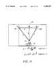
- FIG. 11illustrates the relationship between the position of the detectors on the writing surface and the position of the stylus on the writing surface.
- FIG. 12illustrates a data structure for an input section table.
- FIG. 13is a process flow for a calibration module.
- FIG. 14is a process flow for an image creation flow.
- the present inventionrelates to a system, instruments used in the system, and a method for recording writing performed on a surface.
- Writingis intended to include the formation of any type of image on a surface, including printing, drawing, sketching and the like.
- the surface on which the writing is performedmay be any surface on which writing may be performed.
- the surfaceis preferably a relatively smooth flat surface. Examples of suitable surfaces include but are not limited to whiteboards, blackboards, clipboard, desktops, and walls, whether or not covered by a material such as paper or plastic which can be written upon.
- a stylusincluding a housing and a writing element is provided.
- the writing elementmay optionally be removable from the housing.
- two or more detectorswhich may be permanently or removably affixed to a writing surface and are used in combination with the stylus to detect the position of the stylus on the writing surface.
- hardwarefor controlling when reference and position signals, described herein, are sent between the stylus and the two or more detectors.
- the systemmay also include a processing unit which contains logic and processing capabilities for performing the various calibration and calculation functions necessary to determine the position of the stylus relative to the two or more detectors at multiple times over a period of time that the stylus is used to write.
- the systemmay produce signals corresponding to timing data which can be communicated to a processor external to the system for providing positioning data.
- Incorporated into the stylus and the plurality of detectorsare one or more transmitters for transmitting a ranging medium and one or more receivers for receiving the ranging medium. Used in combination, the one or more transmitters and one or more receivers determine a separation between the stylus and the plurality of detectors based on a time of flight of the ranging medium between them which can be used to determine a positioning of the stylus.
- a variety of ranging mediacan be used including, for example, ultrasound and radar.
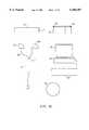
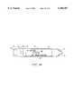
- FIG. 1Aillustrates one embodiment of a transcription system according to the present invention.
- the systemincludes a stylus 10, a first detector 12A, a second detector 12B, and a hardware unit 14.
- the systemcan optionally also include an eraser 16, calibration pad 18, processing unit 20, monitor 22, and user interface 24.
- signals from the first detector 12A and the second detector 12Bmay be transmitted to the hardware unit 14 through a wire 26. These signals may be electrical or optical in nature.
- the signalscan also be transmitted wirelessly to the hardware unit 14, for example through a form of electromagnetic radiation.
- the systemcan also be designed such that signals are transmitted to the hardware unit 14 from the stylus 10. Again, these signals may be transmitted to the hardware unit 14 through a wire 26 or wirelessly.
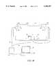
- FIG. 1Billustrates how the transcription system illustrated in FIG. 1A may be installed relative to a writing surface 28.
- the first detector 12A and the second detector 12Bare removably coupled to the writing surface 28.
- the first detector 12A and the second detector 12Bmay be embodied in a single element where the first detector 12A and the second detector 12B are separated from each other by a fixed distance (not shown).
- the first detector 12A and the second detector 12Bmay optionally be permanently attached to the writing surface 28.
- the first detector 12A and second detector 12Bcan be placed anywhere on the writing surface 28. However, it is generally preferred that the first detector 12A and the second detector 12B be positioned adjacent an edge, preferably a corner of the writing area 32 of the writing surface 28.
- the calibration pad 18is preferably positioned at a distance from the first detector 12A and the second detector 12B.
- the calibration pad 18is illustrated as being positioned on an opposite side of the writing area 32 relative to the first detector 12A and the second detector 12B.
- the calibration pad 18is more preferably positioned approximately equidistant from each of the first detector 12A and the second detector 12B on the opposite side of the writing area 32 from the first detector 12A and the second detector 12B.
- the calibration pad 18is shown to be removably attachable to the writing surface 28, it is noted that the calibration pad 18 may also optionally be permanently attached to the writing surface 28.
- One advantage of the transcription system of the present inventionis the ability of the transcription system to be readily attached to and detached from different writing surfaces. This enables the transcription system to be portable and be used with different writing surfaces and with different sized writing surfaces.
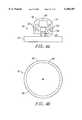
- FIG. 1Cillustrates the use of the calibration pad 18 to calibrate the transcription system.
- the transcription systemis used with different writing surfaces and with different sized writing surfaces, it may be necessary to calibrate the system.
- the usercontacts two or more different calibration points 36 of the calibration pad 18 with the stylus 10.
- the processing unit 20may optionally produce a calibration pad image 38 on the monitor 22 to direct a user with regard to how to calibrate the system.
- the calibration pad image 38can show a stylus 10 contacting a calibration point 36 of the calibration pad image 38.
- the usercan contact the stylus 10 with the calibration point 36 of the calibration pad 18 as illustrated.
- the transcription systemwill be calibrated after the user follows the sequence of prompts. Because the transcription system is easily calibrated by the user, the transcription system is readily usable with different sized writing surfaces.
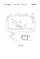
- the systemis generally ready for use. As illustrated in FIG. 1D, the user can write in the writing area 32 with the stylus 10. While the user is creating an image in the writing area 32, a similar image appears on the monitor 22.
- the image in the writing area 32is called the written image 42 and the image on the monitor 22 is called the monitor image 44.
- the monitor image 44can be stored for later manipulation or for forwarding to another location.
- the written image 42can also be erased using an eraser 16. As illustrated in FIG. 1E, the monitor image 44 is erased as the written image 42 is erased using the eraser 16.
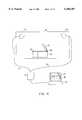
- the calibration pad 18can be designed to perform a variety of different system functions. For example, placing the stylus 10 in a particular input section of the calibration pad 18 can cause the monitor image 44 to be saved, cause the monitor image 44 to be erased, create a new file into which a new monitor image 44 may be recorded, enable or disable selected functions, change or select the color of the monitor image 44 being drawn using the stylus 10.
- additional system functionscan be envisioned and are intended to fall within the scope of the present invention.
- the calibration pad 18can be constructed from any flat material suitable for attaching to a flat surface.
- the input section 46can be defined with different colored section of the calibration pad 18 or outlined section of the calibration pad 18.
- the input sections 46 of the calibration pad 18allow the user to control the monitor image 44 without using the user interface 24.
- the transcription systemrecords the written image 42 by detecting the position of the stylus 10 on the writing surface 28 at multiple times, each position detected serving to form a point on the monitor image 44.
- a continuous monitor image 44can be recorded.
- each pointis determined based on the time that it takes for the ranging medium to travel between the stylus 10 and the first detector 12A and the second detector 12B. This time is called the position signal's time of flight.
- FIG. 2Aillustrates an embodiment where the stylus 10 includes at least one reference signal receiver 50 and a position signal transmitter 52. Meanwhile, the first detector 12A and the second detector 12B each include a position signal receiver 54. Located somewhere in the system is a reference signal transmitter 56. In FIG. 2A, the reference signal transmitter 56 is included in the second detector 12B. In other embodiments, the reference signal transmitter 56 can be included in the hardware unit 14.
- a reference signal 58is transmitted to the stylus 10 which instructs the stylus 10 to transmit a position signal 60.
- the position signal 60is propagated radially from the stylus 10 and received by the first detector 12A and the second detector 12B at a time that is dependent on the distance between the stylus 10 and each of the first detector 12A and the second detector 12B at the time that the position signal 60 is produced. Since the position signal 60 is transmitted at a known time after the reference signal 58 is transmitted, the time of flight of the position signal 60 to each detector can be determined.
- the hardware unit 14receives position signals 60 from each detector and controls the transmission of the reference signals 58 from the reference signal transmitter 56.
- the hardware unit 14uses the received position signals 60 to determine the time of flight of the position signal 60 from the stylus 10 to the first detector 12A and the second detector 12B.
- the time of flightis received by the processing unit 20 which includes logic for using the time of flight data to determine the position of the stylus 10 relative to the first detector 12A and the second detector 12B.
- the logicmay employ a variety of methodologies for determining the position of the stylus 10 including, for example, triangulation or a look-up table containing different positions associated with different times of flight to each detector.
- reference signals 58may be used.
- the reference signal 58should be at least as fast as the position signal 60 and is preferably significantly faster than the position signal 60.
- the reference signal 58is significantly faster than the position signal 60 (e.g., speed of light vs. speed of sound)
- the reference signal 58travels at the speed of sound and in another travels at the speed of light.
- the reference signal 58is a form of electromagnetic radiation, such as infra-red (IR) light.
- position signals 60may be used.
- the position signal 60is ultrasound.
- the position signal 60is a form of electromagnetic radiation, such as radar, preferably micro-impulse radar.
- FIG. 2Billustrates an alternative embodiment where the stylus 10 includes a position signal transmitter 52 and is physically attached to the hardware unit 14 by a wire 62. Meanwhile, the first detector 12A and the second detector 12B each include a position signal receiver 54.
- a reference signal 58is transmitted to the stylus 10 from the hardware unit 14 via the wire 62.
- the stylus 10transmits a position signal 60 which propagates radially from the stylus 10 and is received by the first detector 12A and the second detector 12B at a time that is dependent on the distance between the stylus 10 and the first detector 12A and the second detector 12B at the time that the position signal 60 is produced. Since the position signal 60 is transmitted at a known time after the reference signal 58 is transmitted, the time of flight of the position signal 60 to each detector can be determined.
- FIG. 2Cillustrates an alternative embodiment where the stylus 10 includes a position signal transmitter 52 and the first detector 12A and the second detector 12B each include position signal receivers 54.
- the stylus 10also includes a reference signal transmitter 56 and the second detector 12B, called the reference detector 66, includes a reference signal receiver 50 in addition to the position signal receiver 54.
- a reference signal 58is transmitted by the stylus 10 to the reference detector 66 to signal that a position signal 60 is being transmitted or is about to be transmitted.
- a position signal 60is transmitted which is received by the first detector 12A and the second detector 12B. Since the position signal 60 is transmitted at a known time after the reference signal 58 is transmitted, the time of flight of the position signal 60 to each detector can be determined by the processing unit 20.
- the reference signal 58 and the position signal 60can be transmitted together for each point in the monitor image 44.
- the position signal 60can also be transmitted without the reference signal 58.
- the reference signal 58can serve to synchronize the stylus 10 and the hardware housing and/or the processing unit 20.
- the stylus 10is configured to transmit a series of position signals 60 at a known time interval.
- the reference signal 58indicates when the first position signal 60 in the series is transmitted.
- the processing unit 20includes a timer which is started after receiving the reference signal 58.
- the first time of flight determination for a particular detectoris made by measuring the time between starting the timer and receiving the position signal 60 at the particular detector.
- the hardware housing and/or the processing unit 20can include logic for determining when each subsequent position signal 60 is transmitted.
- the time of flight to a particular detectorcan be calculated by determining the time between when the position signal 60 is transmitted and when the position signal 60 is received at that detector.
- FIG. 2Dillustrates yet an alternative embodiment where the stylus 10 includes a position signal receiver 54 and a reference signal transmitter 56.
- the first detector 12A and the second detector 12Binclude position signal transmitters 52 and reference signal receivers 50. It is noted that this embodiment can be readily varied where the stylus 10 includes a reference signal receiver 50 and one or both of the first detector 12A and the second detector 12B include a reference signal transmitter 56.
- each detectortransmits a different position signal 60 which can be distinguished by the position signal receiver(s) 54 on the stylus 10.
- the stylus 10receives one or more of the position signals 60, the stylus 10 transmits a reference signal 58 to confirm receipt of the position signal 60 and request that the next position signals 60 be sent.
- FIG. 3Aillustrates an embodiment of a stylus 10 which can be used with the system illustrated in FIG. 2A.
- the stylus 10includes a stylus housing 70 and a writing element 72.
- Suitable writing elements 72include, but are not limited to, an inkwell, chalk, pencil, pencil lead, pen and a marker such as a SANFORD EXPO.
- the stylus housing 70includes a tip end 74 with a position signal transmitter 52.
- the stylus housing 70also includes a power source 76, a contact switch 78 and an electronics housing 80 and a plurality of reference signal receivers 50.
- the stylus housing 70may be designed such that the writing element 72 is removable from the stylus housing 70.
- the stylus housing 70may include a cap 82 and a sleeve 84 which may be attached and detached from each other, the sleeve 84 including a volume 86 within which the writing element 72 may be positioned, the cap 82 serving to maintain the writing element 72 within the sleeve 84.
- the writing element 72can be replaced when writing media contained in the element is exhausted or a different writing media (type or color) is desired.
- the tip 88 of the replacement writing instrumentis inserted through the stylus housing 70 and into the tip end 74 of the stylus 10.
- the cap 82is placed on the stylus 10 so the rear 90 of the writing instrument is in contact with the contact switch 78.
- the contact switch 78can be used to indicate when the stylus 10 is being used to write.
- the contact switch 78typically works based on pressure being exerted between the stylus 10 and a writing surface 28. In operation, the stylus 10 is held such that the tip 88 of the writing instrument is contacted with the writing surface 28. The pressure of the writing instrument on the writing surface 28 closes the contact switch 78 and activates a circuit within the electronics housing 80.
- an activation signalis provided to the system to indicate that the stylus 10 has been contacted with the writing surface 28.
- the propagation of reference and position signals 60can be initiated in response to the activation signal.
- the activation signalmay be a position signal 60 or a reference signal 58 transmitted from the stylus 10.
- a deactivation signalmay be transmitted to the system.
- the systemcan also detect when the electronics housing 80 has been deactivated by detecting that a position signal, or reference signal 58, has not been transmitted from the stylus 10 for some predetermined period of time.
- the stylus 10includes reference signal receivers 50. These receivers are preferably evenly spaced around the stylus 10 so that reference signals 58 can be received from any angle relative to the stylus 10.
- the reference signal receiver 50is an IR signal receiver. Suitable IR receivers include, but are not limited to photodiodes.
- the stylus 10includes a position signal transmitter 52.
- the position signal transmitter 52is an ultrasound transmitter.
- Suitable ultrasound transmittersinclude, but are not limited to, Polaroid L Series ultrasonic emitters, cylindrical polyvinylidene fluoride (PVDF) rings and similar piezotransducing elements.
- Suitable position signals 60include, but are not limited to, a 40 kHz signal emitted for approximately 0.7 ms.
- FIG. 3Cillustrates an embodiment of the stylus 10 which can be used with the transcription system illustrated in FIG. 2B.
- the electronics housing 80is coupled to the system via the electrical wire 62.
- the reference signal 58can be transmitted to the stylus 10 via the wire 62.
- the position signal 60is transmitted from the position signal transmitter 52 in response to receiving the reference signal 58.
- the stylus 10can also be adapted to be used in a transcription system such as the one illustrated in FIG. 2C.
- the stylus 10can include a reference signal transmitter 56 and a position signal transmitter 52.
- the detectors 12A, 12Bcan be modified to include a reference signal receiver 50 and a position signal receiver 54.
- the stylus 10can also be adapted to be used in a transcription system such as the one illustrated in FIG. 2D.
- the stylus 10can include a reference signal transmitter 56 and a position signal receiver 54.
- the detectors 12A, 12Bcan be modified to include a position signal transmitter 52.
- a reference signal receiver 50is also provided in the system and may optionally be incorporated into one of the detectors 12A, 12B.
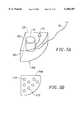
- FIG. 4Aillustrates an eraser 16 which may be used in a system according to the present invention.
- the eraser 16 illustratedincludes a holding surface 92, an eraser pad 94, a position signal transmitter 52, a reference signal receiver 50, a contact switch 78 and an electronics housing 80. It is noted that this eraser 16 is designed for use in a transcription system such as the one illustrated in FIG. 2A. However, the eraser 16 can be modified, as described above with regard to the stylus 10, for use with different transcription systems.
- the eraser 16is positioned such that the eraser pad 94 is pushed against the writing surface 28.
- the eraser pad 94is constructed form a material which erases the writing element 72 media on the writing surface 28.
- the eraser pad 94can be a typical white board eraser material.
- contact between the eraser pad 94 and the writing surface 28can serve to erase a portion of the writing image from the writing area 32.
- the pressure of the eraser pad 94 on the writing surface 28drives the eraser pad 94 against the contact switch 78, closing the contact switch 78 and activating a circuit within the electronics housing 80.
- Activating the circuit within the electronics housing 80can serve to signal the eraser 16's operation to the hardware unit 14 and/or the processing unit 20 in a similar manner as discussed with respect to the stylus 10.
- a reference signal 58 received at one of the reference signal receivers 50triggers a position signal 60 to be transmitted from the position signal transmitter 52.
- the reference signal receivers 50are preferably evenly spaced around the eraser 16 so a reference signal 58 can be received from different angles around the eraser 16.
- the reference signal receivers 50 and the position signal transmitter 52can be similar to the reference signal receivers 50 and the position signal transmitter 52 used in the stylus 10.
- the signal transmitted by the position signal transmitter 52 on the eraser 16can optionally be different from the signal transmitted by the position signal transmitter 52 on the stylus 10.
- the hardware unit 14 and/or the processing unit 20can then distinguish that the signal being received is from the eraser 16 as opposed to the stylus 10.
- the transcription systemdetects that it is receiving signals from the eraser 16 the transcription system can erase the monitor image 44 according to the position of the eraser 16 on the writing surface 28.
- the processing unit 20will detect the position of the position signal transmitter 52 as illustrated in FIG. 4B. However, the portion of the written image 42 which is erased is the portion of the written image 42 in contact with any portion of the eraser pad 94 and not simply the position of the position signal transmitter 52. Accordingly, the processing unit 20 includes logic which accounts for the portion of the written image 42 actually contacted by the eraser pad 94. The processing unit 20 calculates an approximate eraser area 96 which matches the eraser pad footprint 98. As the eraser 16 is moved about the writing surface 28, the portion of the monitor image 44 which falls within the approximate eraser area 96 is erased from the monitor image 44. The size of the approximate eraser area 96 can be adjusted so it matches the actual size of the eraser pad footprint 98. Similarly, the approximate eraser area 96 can be calculated to have different shapes which match the shape of the eraser pad footprint 98.
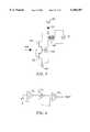
- FIG. 5Aillustrates an embodiment of the reference detector 66 which may be used with the transcription system illustrated in FIG. 2A.
- the reference detector 66includes a detector housing 100, a position signal receiver 54 and a reference signal transmitter 56.
- the reference signal transmitter 56is preferably positioned in an upper surface 102 of the detector housing 100.
- An example of an ultrasound receiver that may be usedis the Polaroid L Series Ultrasonic Receiver.
- An example of a reference signal transmitter 56 that may be usedis an IR transmitter.
- the position signal receiver 54may be coupled to the hardware unit 14 through a wire 62 connection (or a wireless connection) in order to communicate to the hardware unit 14 when position signals 60 are received by the reference detector 66.
- the reference signal transmitter 56is in electronic communication with the position signal receiver 54 (either directly or through the hardware unit 14) such that a signal is sent to the reference signal transmitter 56 to transmit a signal once certain position signals 60 are received by the position signal receiver 54.
- a lower surface 108 the detector housing 100includes one or more attachment mechanisms 110 for removably attaching the detector housing 100 to the writing surface 28.
- suitable attachments mechanismsinclude, but are not limited to, suction cups, magnets, VELCRO or a refreshable contact cement. It is also envisioned that mounting brackets may also be attached to the writing surface 28 which may obviate the need for an attachment mechanism.
- the reference detector 66may also be adapted for use with the transcription system of FIG. 2B, for example, by removing the reference signal transmitter 56 from the upper surface 102 of the detector housing 100.
- the reference detector 66may also be adapted for use with the transcription system of FIG. 2C by replacing the reference signal transmitter 56 with a reference signal receiver 50.
- Suitable reference signal receivers 50include, but are not limited to, a photodiode.
- the reference detector 66may also be adapted for use with the transcription system of FIG. 2D by replacing the reference signal transmitter 56 with a reference signal receiver 50 and by replacing the position signal receiver 54 with a position signal transmitter 52.
- FIG. 6illustrates a circuit diagram for controlling the transmission and emission of the various reference signals 58 and position signals 60 and for determining the time for a detector to receive a position signal 60.
- the stylus 10includes a reference signal receiver 50 coupled with a trigger circuit 122 which is coupled with a position signal transmitter 52.
- the trigger circuit 122triggers the transmission of a position signal 60 in response to receiving a reference signal 58.
- the first detector 12Aincludes a position signal receiver 54 coupled with a first detector circuit 124.
- the reference detector 66includes a reference signal transmitter 56, and a position signal receiver 54 coupled with a second detector circuit 126.
- the detector circuitsprovide a signal when the position signal receiver has received a position signal.
- the output from the first detector circuitis received by a first timer 128 and a first toggle included in a processor 130.
- the output from the second detector circuit 126is received by a second timer 132 and a second toggle included in the processor 130.
- the first timer 128, the second timer 132 and the processor 130can be located within the hardware unit 14 and/or the processing unit 20.
- the hardware unit 14 and/or the processing unit 20includes a hardware controller 134.
- the hardware controller 134periodically provides a DRV -- XMIT signal on a DRV -- XMIT line.
- the DRV -- XMIT signalis received by the first timer 128, the second timer 132, a third toggle in the processor 130 and the reference signal transmitter 56 in the reference detector 66.
- the DRV -- XMIT signalis also received by a timeout counter 136.
- the hardware controller 134provides a DRV -- XMIT signal which causes the reference signal transmitter 56 to transmit a reference signal 58, resets the first and second timers and asserts a toggle within the processor 130.
- the reference signal receiver 50receives the reference signal 58.
- the trigger circuit 122triggers the position signal transmitter 52 to transmit a position signal 60.
- the position signal receiver 54 within the first detector 12Areceives the position signal 60 and the first detector circuit provides a signal indicating that a position signal 60 has been received.
- the signal from the first detector circuitstops the first timer 128 and asserts the second toggle in the processor 130.
- the position signal receiver 54 in the reference detector 66receives the position signal 60 and the second detector circuit 126 provides a signal indicating that a position signal 60 has been received.
- the signal from the second detector circuit 126stops the second timer 132 and asserts the third toggle in the processor 130.
- an RCV -- DONE? signalis received by the hardware controller 134.
- the hardware controller 134sequentially activates the amplifiers 140.
- the data from the first timer 128is received on a bus 142 via the amplifiers 140.
- the data from the second timer 132is received on the bus 142 via the amplifiers 140.
- the DRV -- XMIT signalis provided again.
- the timeoutis set to the amount of time for a position signal 60 to be transmitted across the diagonal dimension of the writing area 32.
- the circuit 120 illustrated in FIG. 6can be readily adapted for use with other transcription systems embodiments, such as the transcription system embodiments illustrated in FIGS. 2B-2D.
- the reference signal transmitter 56 and the reference signal receiver 50can be replaced with a wire for carrying the reference signal 58.
- the trigger circuit 122triggers the position signal transmitter 52 to transmit a position signal 60 in response to a reference signal receiver 50 receiving a reference signal 58.
- the circuitcan be included in the stylus 10 or in the eraser 16.
- the trigger circuit 122includes a first transistor 150, a second transistor 152, a third transistor 154, a first node 156, a second node 158 and a transformer 160.
- a power source 162is coupled with the first node 156. Suitable power sources 162 include, but are not limited to, a battery such as a 4.5 V battery.
- the first nodeis coupled with the collector of the first transistor.
- Suitable first transistorsinclude, but are not limited to, an NPN Bipolar Junction Transistor.
- the emitter of the first transistoris coupled with the emitter of the second transistor and also with the base of the third transistor.
- Suitable second transistorsinclude, but are not limited to, PNP Bipolar Junction Transistors.
- Suitable third transistorsinclude, but are not limited to, an NMOS transistor.
- the collector of the second transistoris coupled with a ground 164.
- An IR detectorcan be coupled with the second node via an amplifier (not shown).
- the second nodeis coupled with the base of the first and second transistor.
- the first nodeis also coupled with the transformer.
- a suitable transformertransforms a 4.5 V signal to a 225 V signal.
- the transformeris coupled with the source of the third transistor.
- the drain of the third transistoris coupled with the ground.
- the transformeris coupled with the ultrasound transducer.
- the second nodecan also be coupled with the hardware housing as illustrated in FIG. 2B.
- the ultrasound position signal 60is triggered by a reference signal 58 received via the electrical wire 62.
- FIG. 8illustrates a detector circuit which may be used in the circuit 120 illustrated in FIG. 6.
- the detector circuitis typically housed within the detector but may be positioned in another location within the system.
- the circuit 120includes an amplifier 170, a low pass filter 172 and a comparator 174.
- the position signal transmitter 52is coupled with the amplifier.
- the amplifieris coupled with the low pass filter.
- the low pass filteris coupled with the comparator. As a result, when the signal from the low pass filter rises above some threshold value a signal is provided from the comparator to indicate that the position signal 60 has been detected.
- FIG. 9provides a schematic of an embodiment of a processing unit 20.
- the processing unit 20 illustratedincludes a processor 178 in communication with a volatile memory 180, and a storage unit 182.
- the processor 178is also in communication with the bus illustrated in FIG. 6 via a serial port.
- Suitable processors 178include, but are not limited to, microprocessors and CPUs.
- the storage untilcan include program code and various data tables.
- the volatile memory 180is utilized during execution of the program code included in the storage unit 182.
- the program codecan include a calibration module, an image creation module, an image erase module and a system management module.
- the program codecan also optionally include handwriting recognition software for converting the monitor image 44 directly into ASCII text or converted directly into presentation software such as Microsoft Power Point.
- the calibration moduleguides the user in calibrating the system and calculates the dimensions of the writing area 32.
- the calibration modulemay be accessed when the user installs the transcription system and can be accessed at the command of the user when the user feels the system may have become uncalibrated.
- the distance between the first detector 12A and the second detector 12B, Wis determined and the Height of the writing area, H, is determined.
- the calibration modulealso determines the time for a position signal 60 to travel across a diagonal of the writing surface 28. This time is called the timeout limit.
- the image creation modulecan be accessed after the calibration module.
- the image creation modulecreates the monitor image 44 as the written image 42 is being created.
- the image creation modulealso stores the monitor image 44 as the written image 42 is being created.
- FIG. 10illustrates a data structure for an image table which can be stored in the storage device.
- the image tableincludes a column of x' fields 190 correlated with a y' 190 fields. Each pair of correlated x' fields and y' fields lists the normalized Cartesian coordinates for a position of the stylus 10 on the writing area.
- the monitor image 44can be created by forming lines between sequential positions in the image table to form a figure. Certain rows can include entries which indicate that the stylus 10 was removed from the writing surface 28. These entries are created when an activation or deactivation signal has been received as discussed above. When such an entry exists, lines are drawn between the series of positions following the entry but not between positions on opposite sides of the entries. As a result, a second figure is created which is independent of the first figure.
- the normalized Cartesian coordinatescan be calculated by determining the position of the stylus 10 relative to the first detector 12A and the second detector 12B.
- FIG. 11illustrates the relationship between the detector positions, (0, 0) and (W, 0), and the stylus 10 position (x, y).
- the dimension Wis the width between the first detector 12A and the second detector 12B. W is determined during the calibration module along with the height of the writing area, H.
- the detector in the upper left corner of the writing area 32is presumed to be positioned at the origin, (0,0) in Cartesian coordinates.
- the detector in the upper right corneris presumed positioned at (W, 0).
- the distances r and 1can be calculated by multiplying the time for the position signal 60 to travel between the detectors 12A, 12B and the stylus 10 by the speed of sound. At standard temperature and pressure, the speed of sound is about 1088 ft/s (31.7 mi/s).
- W, r and 1are known, the position of the stylus 10 on the writing area 32 can be determined by calculating (x, y).
- the normalized Cartesian coordinates (x', y') of the stylus 10can then be determined by dividing x by W and dividing y by H.
- FIG. 12illustrates a data structure for an input section table which can be stored in the storage unit 182.
- the input section tableincludes a function field 198, an x' upper left corner field 200, a y' upper left corner field 202, an x' upper right corner field 204, a y' upper right corner field 206, an x' lower left corner field 208, a y' lower left corner field 210, an x' lower right corner field 212 and a y' lower right corner field 214.
- the function field 198lists the function that the computer will perform when the stylus 10 is positioned within a particular input section 46 of the calibration pad 18.
- the x' upper left corner field 200 and the y' upper left corner field 202lists the normalized Cartesian coordinates of the upper left corner of the input section 46 that will perform the function listed in the function field 198. Similarly, the remaining fields list the normalized Cartesian coordinates for each corner of the input section 46 which will perform the listed function. As a result, the input section table lists coordinates which define the position of each input section 46 on the calibration pad 18.
- Controlis passed from the start block 220 to process block 222.
- process block 222the user is directed to touch the stylus 10 to the upper left corner of the calibration pad 18.
- the directiontakes the form of creating a calibration pad image 38 on the monitor 22 and showing a stylus 10 contacting the upper left corner of the calibration pad 18 as discusses with respect to FIG. 1C.
- Controlis then passed to process block 224 where the time for the position signal 60 to pass from the stylus 10 to the first detector 12A and the second detector 12B, t 1 and t 2 , is accessed from the bus.
- Controlis then passed to process block 226 where the r and 1 of Equation 1 and Equation 2 are calculated by multiplying t 1 and t 2 by the speed of sound. The calculated r and 1 are stored as r, and 1 1 . Control is then passed to process block 228 where the user is directed to touch the stylus 10 to the upper right corner of the calibration pad 18. Control is then passed to process block 230 where the time for the position signal 60 to pass from the stylus 10 to the first detector 12A and the second detector 12B, t 1 and t 2 , is accessed from the bus. Control is then passed to process block 232 where the r and 1 are calculated by multiplying t 1 and t 2 by the speed of sound. The calculated r and 1 are then stored as r 2 and 1 2 .
- Controlis passed from process block 232 to process block 234.
- the stored dimensions r 1 , 1 1 , r 2 , 1 2are used with the known width of the calibration pad 18 to solve several linear equations to determine W. W is then stored for later use.
- Controlis then passed to process block 236 where W and is used to determine the height of the detectors 12A, 12B above the calibration pad 18, h.
- the height of the writing area, His then determined by adding the height of the calibration pad 18 and h. H is then stored for later use.
- Controlis then passed to process block 238 where H and W are used to calculate the diagonal length of the writing area 32.
- the time for a position signal 60 to travel that diagonalis determined by dividing the length of the diagonal by the speed of sound. The determined time is stored as the timeout limit.
- Controlis then passed to process block 240 where the position of each of the input sections 46 on the calibration pad 18 are determined.
- W, r 1 , and 1 1are used in Equation 1 and Equation 2 of FIG. 11 to determine the position of the upper left corner of the calibration pad 18.
- This relationis used to determine the Cartesian coordinates of each corner of the input sections 46. These coordinates are then normalized and stored in the appropriate fields of the input section table.
- Controlis passed from process block 240 to process block 242.
- the ratio of W:His then calculated and used to define an monitor image area 243 as illustrated in FIG. 1D.
- the monitor image areais the position on the monitor 22 where the monitor image 44 will be formed.
- the ratio of the length and width of the monitor image areais equal to the ration of W:H. Control is then passed to the exit block 244.
- a process flow of the image creation moduleis illustrated in FIG. 14. Control is passed from the start block 250 to process block 252. At process block 252, the bus is monitored until a time for the position signal 60 to pass from the stylus 10 to the first detector 12A and the second detector 12B, t 1 and t 2 , is received. Control is then passed to process block 254 where r and 1 are calculated by multiplying t 1 and t 2 by the speed of sound. Control is then passed to process block 256 where Equation 1 and Equation 2 of FIG. 11 are used to determine x and y. Control is then passed to process block 258 where x is normalized by dividing x by W and y is normalized by dividing y by H. The normalized x and y define a normalized position of the stylus 10, (x',y').
- Controlis passed from process block 258 to decision block 260.
- decision block 260a determination is made whether the position defined by (x', y') is within any of the input sections 46 of the calibration pad 18. The determination can be made by comparing the (x', y') with the coordinates sets listed in the input section table. When the determination is negative, control is passed form decision block 260 to process block 262 where the current position of the stylus 10 is stored in the image table.
- Controlis passed from process block 262 to process block 264 where the image table is filtered. A moving average of a series of positions in the position table is performed and the positions outside a pre-determined limit rejected. Control is then passed to process block 266 where the image table is compressed. A single line can be represented as only two positions. As a result, redundant positions along a line can be eliminated to reduce the number of positions necessary to create the monitor image 44.
- the compressioncan take the form of fitting the series of positions to a more compact form such as a spline.
- Controlis passed from process block 266 to process block 268 where the monitor image 44 is updated.
- the monitor image areahas a height:width ratio equal to the ration of H:W.
- the height and width of the monitor image areaare each assigned values of 1.0.
- the normalized position coordinateswill define a position on the monitor image area which is proportionate to the position of the stylus 10 on the writing area 32.
- the monitor image 44is then updated by creating a line between the most recent entry in the image table and the previous entry in the image table. Control is then returned to process block 252.
- controlis passed to process block 270.
- the function listed in the function field correlated with the input section 46 where the stylus 10 is positionedis performed. For instance, a new monitor image area may be placed on the monitor 22 so a new monitor 22 can be created or the previous monitor 22 may be saved. After the function is performed, control is returned to process block 252.
- the processing unit 20can also include logic which allows the creation of the monitor image 44 to be played back to the user. As a result, the user can re-capture information which has been erased or can extract information from the actual creation of the monitor image 44. Further, the user can stop the playback at a particular point and edit the image at the point where it was stopped.
Landscapes
- Engineering & Computer Science (AREA)
- General Engineering & Computer Science (AREA)
- Theoretical Computer Science (AREA)
- Physics & Mathematics (AREA)
- Human Computer Interaction (AREA)
- General Physics & Mathematics (AREA)
- Acoustics & Sound (AREA)
- Position Input By Displaying (AREA)
Abstract
Description
Claims (17)
Priority Applications (20)
| Application Number | Priority Date | Filing Date | Title |
|---|---|---|---|
| US09/079,430US6104387A (en) | 1997-05-14 | 1998-05-14 | Transcription system |
| US09/273,883US6147681A (en) | 1998-05-14 | 1999-03-22 | Detector for use in a transcription system |
| US09/274,137US6177927B1 (en) | 1998-05-14 | 1999-03-22 | Transcription system kit |
| US09/274,136US6111565A (en) | 1998-05-14 | 1999-03-22 | Stylus for use with transcription system |
| US09/273,887US6191778B1 (en) | 1998-05-14 | 1999-03-22 | Transcription system kit for forming composite images |
| US09/274,267US6124847A (en) | 1998-05-14 | 1999-03-22 | Collapsible detector assembly |
| US09/273,593US6211863B1 (en) | 1998-05-14 | 1999-03-22 | Method and software for enabling use of transcription system as a mouse |
| US09/274,139US6100877A (en) | 1998-05-14 | 1999-03-22 | Method for calibrating a transcription system |
| PCT/US1999/009879WO1999059130A1 (en) | 1998-05-14 | 1999-05-05 | Transcription system |
| JP2000548862AJP2002515619A (en) | 1998-05-14 | 1999-05-05 | Transcription system |
| EP99922810AEP1076893A4 (en) | 1998-05-14 | 1999-05-05 | Transcription system |
| AU39723/99AAU3972399A (en) | 1998-05-14 | 1999-05-05 | Transcription system |
| GB9925690AGB2340712B (en) | 1998-05-14 | 1999-05-12 | Transcription system |
| GB9911070AGB2337330B (en) | 1998-05-14 | 1999-05-12 | Transcription system |
| GB9925689AGB2340632B (en) | 1998-05-14 | 1999-05-12 | Transcription system |
| GB9925686AGB2340449B (en) | 1998-05-14 | 1999-05-12 | Transcription system |
| GB9925688AGB2340606B (en) | 1998-05-14 | 1999-05-12 | Transcription system |
| GB9925687AGB2340605B (en) | 1998-05-14 | 1999-05-12 | Transcription system |
| US09/589,534US6232962B1 (en) | 1998-05-14 | 2000-06-07 | Detector assembly for use in a transcription system |
| US09/667,195US6310615B1 (en) | 1998-05-14 | 2000-09-21 | Dual mode eraser |
Applications Claiming Priority (2)
| Application Number | Priority Date | Filing Date | Title |
|---|---|---|---|
| US4648597P | 1997-05-14 | 1997-05-14 | |
| US09/079,430US6104387A (en) | 1997-05-14 | 1998-05-14 | Transcription system |
Related Child Applications (7)
| Application Number | Title | Priority Date | Filing Date |
|---|---|---|---|
| US09/274,137Continuation-In-PartUS6177927B1 (en) | 1998-05-14 | 1999-03-22 | Transcription system kit |
| US09/274,136Continuation-In-PartUS6111565A (en) | 1998-05-14 | 1999-03-22 | Stylus for use with transcription system |
| US09/274,139Continuation-In-PartUS6100877A (en) | 1998-05-14 | 1999-03-22 | Method for calibrating a transcription system |
| US09/274,267Continuation-In-PartUS6124847A (en) | 1998-05-14 | 1999-03-22 | Collapsible detector assembly |
| US09/273,593Continuation-In-PartUS6211863B1 (en) | 1998-05-14 | 1999-03-22 | Method and software for enabling use of transcription system as a mouse |
| US09/273,883Continuation-In-PartUS6147681A (en) | 1998-05-14 | 1999-03-22 | Detector for use in a transcription system |
| US09/273,887Continuation-In-PartUS6191778B1 (en) | 1998-05-14 | 1999-03-22 | Transcription system kit for forming composite images |
Publications (1)
| Publication Number | Publication Date |
|---|---|
| US6104387Atrue US6104387A (en) | 2000-08-15 |
Family
ID=26723979
Family Applications (1)
| Application Number | Title | Priority Date | Filing Date |
|---|---|---|---|
| US09/079,430Expired - LifetimeUS6104387A (en) | 1997-05-14 | 1998-05-14 | Transcription system |
Country Status (1)
| Country | Link |
|---|---|
| US (1) | US6104387A (en) |
Cited By (64)
| Publication number | Priority date | Publication date | Assignee | Title |
|---|---|---|---|---|
| US6266051B1 (en)* | 1997-02-21 | 2001-07-24 | Electronics For Imaging, Inc. | Retrofittable apparatus for converting a substantially planar surface into an electronic data capture device |
| US20010024193A1 (en)* | 1999-12-23 | 2001-09-27 | Christer Fahraeus | Written command |
| US20020055788A1 (en)* | 2000-06-02 | 2002-05-09 | Virtual Ink Corporation | Transcription system network |
| WO2002042991A3 (en)* | 2000-11-21 | 2002-09-26 | Tool Tribe Internat A S | Position detection system, graphical user interface, method and use thereof |
| WO2003001497A1 (en)* | 2001-06-21 | 2003-01-03 | Inmotion E-Pen Ltd. | System for digital ink input from a transponder-stylus |
| US20030058227A1 (en)* | 2001-09-05 | 2003-03-27 | Matsushita Electric Industrial Co., Ltd. | Electronic whiteboard system |
| US20030071798A1 (en)* | 2001-04-23 | 2003-04-17 | Ehud Baron | System and method for transmitting, receiving, and generating digital ink from triangulation data of a transponder-stylus |
| US20030085871A1 (en)* | 2001-10-09 | 2003-05-08 | E-Business Information Technology | Coordinate input device working with at least display screen and desk-top surface as the pointing areas thereof |
| US6587099B2 (en)* | 2000-02-18 | 2003-07-01 | Ricoh Company, Ltd. | Coordinate input/detection device detecting installation position of light-receiving device used for detecting coordinates |
| US20030151596A1 (en)* | 2002-02-08 | 2003-08-14 | Moyne William P. | System and method for recording writing performed on a surface |
| US20040010910A1 (en)* | 2002-06-19 | 2004-01-22 | Brian Farrell | Chip package sealing method |
| US6690354B2 (en)* | 2000-11-19 | 2004-02-10 | Canesta, Inc. | Method for enhancing performance in a system utilizing an array of sensors that sense at least two-dimensions |
| US20040032399A1 (en)* | 2002-08-15 | 2004-02-19 | Fujitsu Limited | Ultrasonic coordinate input apparatus |
| US6774891B2 (en) | 2001-04-06 | 2004-08-10 | Matsushita Electric Industrial Co., Ltd. | Transcription system |
| US20040164972A1 (en)* | 2003-02-24 | 2004-08-26 | Carl Stewart R. | Implement for optically inferring information from a planar jotting surface |
| US6798403B2 (en) | 2000-10-24 | 2004-09-28 | Matsushita Electric Industrial Co., Ltd. | Position detection system |
| US20040201580A1 (en)* | 2003-04-09 | 2004-10-14 | Koji Fujiwara | Pen input/display device |
| US20040229195A1 (en)* | 2003-03-18 | 2004-11-18 | Leapfrog Enterprises, Inc. | Scanning apparatus |
| US20040239651A1 (en)* | 2003-05-27 | 2004-12-02 | Fujitsu Component Limited | Ultrasonic coordinate input apparatus and method |
| US6862020B2 (en)* | 2001-05-31 | 2005-03-01 | Intel Corporation | Providing a user-input device |
| US20050133700A1 (en)* | 2003-12-22 | 2005-06-23 | Buermann Dale H. | Method and apparatus for determining absolute position of a tip of an elongate object on a plane surface with invariant features |
| US20050168437A1 (en)* | 2004-01-30 | 2005-08-04 | Carl Stewart R. | Processing pose data derived from the pose of an elongate object |
| US20060033725A1 (en)* | 2004-06-03 | 2006-02-16 | Leapfrog Enterprises, Inc. | User created interactive interface |
| US20060080609A1 (en)* | 2004-03-17 | 2006-04-13 | James Marggraff | Method and device for audibly instructing a user to interact with a function |
| US20060125805A1 (en)* | 2004-03-17 | 2006-06-15 | James Marggraff | Method and system for conducting a transaction using recognized text |
| US20070024812A1 (en)* | 2005-07-29 | 2007-02-01 | Coretronic Corporation | Projector |
| US7427983B1 (en) | 2002-06-02 | 2008-09-23 | Steelcase Development Corporation | Visual communication system |
| US20080297471A1 (en)* | 2003-09-16 | 2008-12-04 | Smart Technologies Ulc | Gesture recognition method and touch system incorporating the same |
| US7619617B2 (en) | 2002-11-15 | 2009-11-17 | Smart Technologies Ulc | Size/scale and orientation determination of a pointer in a camera-based touch system |
| WO2010078338A1 (en) | 2008-12-30 | 2010-07-08 | Sanford, L. P. | Electronic rechargeable stylus and eraser system |
| US7826641B2 (en) | 2004-01-30 | 2010-11-02 | Electronic Scripting Products, Inc. | Apparatus and method for determining an absolute pose of a manipulated object in a real three-dimensional environment with invariant features |
| US7831933B2 (en) | 2004-03-17 | 2010-11-09 | Leapfrog Enterprises, Inc. | Method and system for implementing a user interface for a device employing written graphical elements |
| US7916124B1 (en) | 2001-06-20 | 2011-03-29 | Leapfrog Enterprises, Inc. | Interactive apparatus using print media |
| US7922099B1 (en) | 2005-07-29 | 2011-04-12 | Leapfrog Enterprises, Inc. | System and method for associating content with an image bearing surface |
| US7961909B2 (en) | 2006-03-08 | 2011-06-14 | Electronic Scripting Products, Inc. | Computer interface employing a manipulated object with absolute pose detection component and a display |
| WO2011090695A1 (en) | 2009-12-29 | 2011-07-28 | Sanford, L.P. | Interactive whiteboard with wireless remote control |
| USRE42794E1 (en) | 1999-12-27 | 2011-10-04 | Smart Technologies Ulc | Information-inputting device inputting contact point of object on recording surfaces as information |
| US20110246948A1 (en)* | 2010-03-30 | 2011-10-06 | Sony Corporation | Image processing apparatus, method of displaying image, image display program, and recording medium having image display program for displaying image recorded thereon |
| US8055022B2 (en) | 2000-07-05 | 2011-11-08 | Smart Technologies Ulc | Passive touch system and method of detecting user input |
| US8089462B2 (en) | 2004-01-02 | 2012-01-03 | Smart Technologies Ulc | Pointer tracking across multiple overlapping coordinate input sub-regions defining a generally contiguous input region |
| USRE43084E1 (en) | 1999-10-29 | 2012-01-10 | Smart Technologies Ulc | Method and apparatus for inputting information including coordinate data |
| US8094137B2 (en) | 2007-07-23 | 2012-01-10 | Smart Technologies Ulc | System and method of detecting contact on a display |
| US8115753B2 (en) | 2007-04-11 | 2012-02-14 | Next Holdings Limited | Touch screen system with hover and click input methods |
| US8120596B2 (en) | 2004-05-21 | 2012-02-21 | Smart Technologies Ulc | Tiled touch system |
| US8149221B2 (en) | 2004-05-07 | 2012-04-03 | Next Holdings Limited | Touch panel display system with illumination and detection provided from a single edge |
| US20120090447A1 (en)* | 2010-10-15 | 2012-04-19 | Yamaha Corporation | Information processing terminal and system |
| US8261967B1 (en) | 2006-07-19 | 2012-09-11 | Leapfrog Enterprises, Inc. | Techniques for interactively coupling electronic content with printed media |
| US8274496B2 (en) | 2004-04-29 | 2012-09-25 | Smart Technologies Ulc | Dual mode touch systems |
| US8289299B2 (en) | 2003-02-14 | 2012-10-16 | Next Holdings Limited | Touch screen signal processing |
| US8339378B2 (en) | 2008-11-05 | 2012-12-25 | Smart Technologies Ulc | Interactive input system with multi-angle reflector |
| US8384693B2 (en) | 2007-08-30 | 2013-02-26 | Next Holdings Limited | Low profile touch panel systems |
| US8405636B2 (en) | 2008-01-07 | 2013-03-26 | Next Holdings Limited | Optical position sensing system and optical position sensor assembly |
| US8432377B2 (en) | 2007-08-30 | 2013-04-30 | Next Holdings Limited | Optical touchscreen with improved illumination |
| US8456418B2 (en) | 2003-10-09 | 2013-06-04 | Smart Technologies Ulc | Apparatus for determining the location of a pointer within a region of interest |
| US8456451B2 (en) | 2003-03-11 | 2013-06-04 | Smart Technologies Ulc | System and method for differentiating between pointers used to contact touch surface |
| US8456447B2 (en) | 2003-02-14 | 2013-06-04 | Next Holdings Limited | Touch screen signal processing |
| US8508508B2 (en) | 2003-02-14 | 2013-08-13 | Next Holdings Limited | Touch screen signal processing with single-point calibration |
| US8599143B1 (en) | 2006-02-06 | 2013-12-03 | Leapfrog Enterprises, Inc. | Switch configuration for detecting writing pressure in a writing device |
| US8692768B2 (en) | 2009-07-10 | 2014-04-08 | Smart Technologies Ulc | Interactive input system |
| US8902193B2 (en) | 2008-05-09 | 2014-12-02 | Smart Technologies Ulc | Interactive input system and bezel therefor |
| US9229540B2 (en) | 2004-01-30 | 2016-01-05 | Electronic Scripting Products, Inc. | Deriving input from six degrees of freedom interfaces |
| US9442607B2 (en) | 2006-12-04 | 2016-09-13 | Smart Technologies Inc. | Interactive input system and method |
| CN111324217A (en)* | 2018-12-13 | 2020-06-23 | 鸿合科技股份有限公司 | Electronic whiteboard, blackboard writing processing method, chalk expanding device and electronic equipment |
| US11577159B2 (en) | 2016-05-26 | 2023-02-14 | Electronic Scripting Products Inc. | Realistic virtual/augmented/mixed reality viewing and interactions |
Citations (61)
| Publication number | Priority date | Publication date | Assignee | Title |
|---|---|---|---|---|
| US33936A (en)* | 1861-12-17 | Improvement in pumps | ||
| US3613066A (en)* | 1968-10-22 | 1971-10-12 | Cii | Computer input equipment |
| US3706850A (en)* | 1971-04-23 | 1972-12-19 | Bell Telephone Labor Inc | Telewriting system |
| US3731273A (en)* | 1971-11-26 | 1973-05-01 | W Hunt | Position locating systems |
| US3838212A (en)* | 1969-07-11 | 1974-09-24 | Amperex Electronic Corp | Graphical data device |
| US4012588A (en)* | 1975-08-29 | 1977-03-15 | Science Accessories Corporation | Position determining apparatus and transducer therefor |
| GB2042726A (en)* | 1979-03-07 | 1980-09-24 | Bransbury R | Pattern Logging Device |
| US4246439A (en)* | 1978-04-10 | 1981-01-20 | U.S. Philips Corporation | Acoustic writing combination, comprising a stylus with an associated writing tablet |
| US4294543A (en)* | 1979-11-13 | 1981-10-13 | Command Control & Communications Corporation | Optical system for developing point coordinate information |
| US4317005A (en)* | 1979-10-15 | 1982-02-23 | Bruyne Pieter De | Position-determining system |
| US4357672A (en)* | 1980-07-30 | 1982-11-02 | Science Accessories Corporation | Distance ranging apparatus and method |
| GB2097922A (en)* | 1981-03-25 | 1982-11-10 | Branton Robert | Positional determination |
| US4488000A (en)* | 1982-09-30 | 1984-12-11 | New York Institute Of Technology | Apparatus for determining position and writing pressure |
| US4506354A (en)* | 1982-09-30 | 1985-03-19 | Position Orientation Systems, Ltd. | Ultrasonic position detecting system |
| US4558313A (en)* | 1981-12-31 | 1985-12-10 | International Business Machines Corporation | Indicator to data processing interface |
| EP0169538A2 (en)* | 1984-07-25 | 1986-01-29 | Hitachi, Ltd. | Tablet type coordinate input apparatus using elastic waves |
| US4577057A (en)* | 1984-03-02 | 1986-03-18 | Pencept, Inc. | Digitizing tablet system having stylus tilt correction |
| US4578768A (en)* | 1984-04-06 | 1986-03-25 | Racine Marsh V | Computer aided coordinate digitizing system |
| US4654648A (en)* | 1984-12-17 | 1987-03-31 | Herrington Richard A | Wireless cursor control system |
| US4670751A (en)* | 1983-01-08 | 1987-06-02 | Fujitsu Limited | Eraser for electronic blackboard |
| US4688933A (en)* | 1985-05-10 | 1987-08-25 | The Laitram Corporation | Electro-optical position determining system |
| US4758691A (en)* | 1986-01-23 | 1988-07-19 | Zellweger Uster Ltd. | Apparatus for determining the position of a movable object |
| EP0284048A2 (en)* | 1987-03-24 | 1988-09-28 | Canon Kabushiki Kaisha | Coordinates input apparatus |
| US4777329A (en)* | 1987-08-24 | 1988-10-11 | Microfield Graphics, Inc. | Graphic input system |
| US4814552A (en)* | 1987-12-02 | 1989-03-21 | Xerox Corporation | Ultrasound position input device |
| WO1989011144A1 (en)* | 1988-05-09 | 1989-11-16 | Conference Communications, Inc. | Interactive overlay driven computer display system |
| US4991148A (en)* | 1989-09-26 | 1991-02-05 | Gilchrist Ian R | Acoustic digitizing system |
| US5023408A (en)* | 1988-06-22 | 1991-06-11 | Wacom Co., Ltd. | Electronic blackboard and accessories such as writing tools |
| US5043950A (en)* | 1990-01-19 | 1991-08-27 | Science Accessories Corp. | Apparatus and method for distance determination |
| US5050134A (en)* | 1990-01-19 | 1991-09-17 | Science Accessories Corp. | Position determining apparatus |
| US5107541A (en)* | 1985-11-05 | 1992-04-21 | National Research Development Corporation | Method and apparatus for capturing information in drawing or writing |
| USRE33936E (en) | 1986-01-09 | 1992-05-26 | Wacom Co., Ltd. | Electronic blackboard apparatus |
| US5142506A (en)* | 1990-10-22 | 1992-08-25 | Logitech, Inc. | Ultrasonic position locating method and apparatus therefor |
| US5144594A (en)* | 1991-05-29 | 1992-09-01 | Cyber Scientific | Acoustic mouse system |
| US5248856A (en)* | 1992-10-07 | 1993-09-28 | Microfield Graphics, Inc. | Code-based, electromagnetic-field-responsive graphic data-acquisition system |
| US5250929A (en)* | 1991-07-29 | 1993-10-05 | Conference Communications, Inc. | Interactive overlay-driven computer display system |
| US5280457A (en)* | 1992-07-31 | 1994-01-18 | The Administrators Of The Tulane Educational Fund | Position detecting system and method |
| US5298737A (en)* | 1991-09-12 | 1994-03-29 | Proper R J | Measuring apparatus for determining the position of a movable element with respect to a reference |
| US5308936A (en)* | 1992-08-26 | 1994-05-03 | Mark S. Knighton | Ultrasonic pen-type data input device |
| US5311207A (en)* | 1990-04-19 | 1994-05-10 | Sony Corporation | Image drawing apparatus for displaying input image on display means |
| WO1994011844A1 (en)* | 1992-11-17 | 1994-05-26 | Lectra Systemes | Graphic data acquisition and processing method and device |
| WO1994016422A1 (en)* | 1993-01-13 | 1994-07-21 | Science Accessories Corp. | Position determining apparatus |
| EP0623872A1 (en)* | 1993-04-28 | 1994-11-09 | Nec Corporation | Apparatus for processing information by executing an operation selected from data processing operations in accordance with a co-ordinate value |
| US5420607A (en)* | 1992-09-02 | 1995-05-30 | Miller; Robert F. | Electronic paintbrush and color palette |
| US5434370A (en)* | 1993-11-05 | 1995-07-18 | Microfield Graphics, Inc. | Marking system with pen-up/pen-down tracking |
| WO1996010817A1 (en)* | 1994-09-30 | 1996-04-11 | Microsonic Gesellschaft für Mikroelektronik und Ultraschalltechnik mbH | Ultrasound sensor |
| US5557301A (en)* | 1991-05-17 | 1996-09-17 | D'aviau De Piolant; Jean-Louis | Graphic drawing system |
| US5576727A (en)* | 1993-07-16 | 1996-11-19 | Immersion Human Interface Corporation | Electromechanical human-computer interface with force feedback |
| US5583323A (en)* | 1993-11-05 | 1996-12-10 | Microfield Graphics, Inc. | Calibration of graphic data-acquisition tracking system |
| EP0772149A1 (en)* | 1995-11-01 | 1997-05-07 | Seiko Instruments Information Devices Inc. | Stylus pen and coordinate reading system using the same |
| US5691959A (en)* | 1994-04-06 | 1997-11-25 | Fujitsu, Ltd. | Stylus position digitizer using acoustic waves |
| WO1998014888A1 (en)* | 1996-10-04 | 1998-04-09 | Microtouch Systems, Inc. | Electronic whiteboard with multi-functional user interface |
| WO1998037508A1 (en)* | 1997-02-21 | 1998-08-27 | Electronics For Imaging, Inc. | Retrofittable apparatus for converting a substantially planar surface into an electronic data capture device |
| WO1998038595A1 (en)* | 1997-02-28 | 1998-09-03 | Electronics For Imaging, Inc. | Marking device for electronic presentation board |
| WO1998038596A1 (en)* | 1997-02-28 | 1998-09-03 | Electronics For Imaging, Inc. | Marking device for electronic presentation board |
| WO1998039729A2 (en)* | 1997-03-05 | 1998-09-11 | Electronics For Imaging, Inc. | Digitizer system for electronic blackboard |
| WO1998040838A2 (en)* | 1997-03-10 | 1998-09-17 | Electronics For Imaging, Inc. | Presentation board digitizer systems |
| US5864335A (en)* | 1993-11-01 | 1999-01-26 | Hitachi, Ltd. | Information processing system |
| WO1999036883A1 (en)* | 1998-01-20 | 1999-07-22 | Electronics For Imaging, Inc. | Improved pen positioning system |
| GB2334003A (en)* | 1996-10-10 | 1999-08-11 | Numonics Corp | Apparatus for an electronic pen |
| US5956020A (en)* | 1995-07-27 | 1999-09-21 | Microtouch Systems, Inc. | Touchscreen controller with pen and/or finger inputs |
- 1998
- 1998-05-14USUS09/079,430patent/US6104387A/ennot_activeExpired - Lifetime
Patent Citations (64)
| Publication number | Priority date | Publication date | Assignee | Title |
|---|---|---|---|---|
| US33936A (en)* | 1861-12-17 | Improvement in pumps | ||
| US3613066A (en)* | 1968-10-22 | 1971-10-12 | Cii | Computer input equipment |
| US3838212A (en)* | 1969-07-11 | 1974-09-24 | Amperex Electronic Corp | Graphical data device |
| US3706850A (en)* | 1971-04-23 | 1972-12-19 | Bell Telephone Labor Inc | Telewriting system |
| US3731273A (en)* | 1971-11-26 | 1973-05-01 | W Hunt | Position locating systems |
| US4012588A (en)* | 1975-08-29 | 1977-03-15 | Science Accessories Corporation | Position determining apparatus and transducer therefor |
| US4246439A (en)* | 1978-04-10 | 1981-01-20 | U.S. Philips Corporation | Acoustic writing combination, comprising a stylus with an associated writing tablet |
| GB2042726A (en)* | 1979-03-07 | 1980-09-24 | Bransbury R | Pattern Logging Device |
| US4317005A (en)* | 1979-10-15 | 1982-02-23 | Bruyne Pieter De | Position-determining system |
| US4294543A (en)* | 1979-11-13 | 1981-10-13 | Command Control & Communications Corporation | Optical system for developing point coordinate information |
| US4357672A (en)* | 1980-07-30 | 1982-11-02 | Science Accessories Corporation | Distance ranging apparatus and method |
| GB2097922A (en)* | 1981-03-25 | 1982-11-10 | Branton Robert | Positional determination |
| US4558313A (en)* | 1981-12-31 | 1985-12-10 | International Business Machines Corporation | Indicator to data processing interface |
| US4488000A (en)* | 1982-09-30 | 1984-12-11 | New York Institute Of Technology | Apparatus for determining position and writing pressure |
| US4506354A (en)* | 1982-09-30 | 1985-03-19 | Position Orientation Systems, Ltd. | Ultrasonic position detecting system |
| US4670751A (en)* | 1983-01-08 | 1987-06-02 | Fujitsu Limited | Eraser for electronic blackboard |
| US4577057A (en)* | 1984-03-02 | 1986-03-18 | Pencept, Inc. | Digitizing tablet system having stylus tilt correction |
| US4578768A (en)* | 1984-04-06 | 1986-03-25 | Racine Marsh V | Computer aided coordinate digitizing system |
| US4578768B1 (en)* | 1984-04-06 | 1989-09-26 | ||
| EP0169538A2 (en)* | 1984-07-25 | 1986-01-29 | Hitachi, Ltd. | Tablet type coordinate input apparatus using elastic waves |
| US4654648A (en)* | 1984-12-17 | 1987-03-31 | Herrington Richard A | Wireless cursor control system |
| US4688933A (en)* | 1985-05-10 | 1987-08-25 | The Laitram Corporation | Electro-optical position determining system |
| US5107541A (en)* | 1985-11-05 | 1992-04-21 | National Research Development Corporation | Method and apparatus for capturing information in drawing or writing |
| USRE33936E (en) | 1986-01-09 | 1992-05-26 | Wacom Co., Ltd. | Electronic blackboard apparatus |
| US4758691A (en)* | 1986-01-23 | 1988-07-19 | Zellweger Uster Ltd. | Apparatus for determining the position of a movable object |
| EP0284048A2 (en)* | 1987-03-24 | 1988-09-28 | Canon Kabushiki Kaisha | Coordinates input apparatus |
| US4777329A (en)* | 1987-08-24 | 1988-10-11 | Microfield Graphics, Inc. | Graphic input system |
| US4814552A (en)* | 1987-12-02 | 1989-03-21 | Xerox Corporation | Ultrasound position input device |
| WO1989011144A1 (en)* | 1988-05-09 | 1989-11-16 | Conference Communications, Inc. | Interactive overlay driven computer display system |
| US5023408A (en)* | 1988-06-22 | 1991-06-11 | Wacom Co., Ltd. | Electronic blackboard and accessories such as writing tools |
| US4991148A (en)* | 1989-09-26 | 1991-02-05 | Gilchrist Ian R | Acoustic digitizing system |
| US5043950A (en)* | 1990-01-19 | 1991-08-27 | Science Accessories Corp. | Apparatus and method for distance determination |
| US5050134A (en)* | 1990-01-19 | 1991-09-17 | Science Accessories Corp. | Position determining apparatus |
| US5311207A (en)* | 1990-04-19 | 1994-05-10 | Sony Corporation | Image drawing apparatus for displaying input image on display means |
| US5142506A (en)* | 1990-10-22 | 1992-08-25 | Logitech, Inc. | Ultrasonic position locating method and apparatus therefor |
| US5557301A (en)* | 1991-05-17 | 1996-09-17 | D'aviau De Piolant; Jean-Louis | Graphic drawing system |
| US5144594A (en)* | 1991-05-29 | 1992-09-01 | Cyber Scientific | Acoustic mouse system |
| US5250929A (en)* | 1991-07-29 | 1993-10-05 | Conference Communications, Inc. | Interactive overlay-driven computer display system |
| US5298737A (en)* | 1991-09-12 | 1994-03-29 | Proper R J | Measuring apparatus for determining the position of a movable element with respect to a reference |
| US5280457A (en)* | 1992-07-31 | 1994-01-18 | The Administrators Of The Tulane Educational Fund | Position detecting system and method |
| US5308936A (en)* | 1992-08-26 | 1994-05-03 | Mark S. Knighton | Ultrasonic pen-type data input device |
| US5420607A (en)* | 1992-09-02 | 1995-05-30 | Miller; Robert F. | Electronic paintbrush and color palette |
| US5248856A (en)* | 1992-10-07 | 1993-09-28 | Microfield Graphics, Inc. | Code-based, electromagnetic-field-responsive graphic data-acquisition system |
| WO1994011844A1 (en)* | 1992-11-17 | 1994-05-26 | Lectra Systemes | Graphic data acquisition and processing method and device |
| US5717168A (en)* | 1992-11-17 | 1998-02-10 | Lectra Systemes | Method and device for capturing and processing graphical information |
| US5379269A (en)* | 1993-01-13 | 1995-01-03 | Science Accessories Corp. | Position determining apparatus |
| WO1994016422A1 (en)* | 1993-01-13 | 1994-07-21 | Science Accessories Corp. | Position determining apparatus |
| EP0623872A1 (en)* | 1993-04-28 | 1994-11-09 | Nec Corporation | Apparatus for processing information by executing an operation selected from data processing operations in accordance with a co-ordinate value |
| US5576727A (en)* | 1993-07-16 | 1996-11-19 | Immersion Human Interface Corporation | Electromechanical human-computer interface with force feedback |
| US5864335A (en)* | 1993-11-01 | 1999-01-26 | Hitachi, Ltd. | Information processing system |
| US5583323A (en)* | 1993-11-05 | 1996-12-10 | Microfield Graphics, Inc. | Calibration of graphic data-acquisition tracking system |
| US5434370A (en)* | 1993-11-05 | 1995-07-18 | Microfield Graphics, Inc. | Marking system with pen-up/pen-down tracking |
| US5691959A (en)* | 1994-04-06 | 1997-11-25 | Fujitsu, Ltd. | Stylus position digitizer using acoustic waves |
| WO1996010817A1 (en)* | 1994-09-30 | 1996-04-11 | Microsonic Gesellschaft für Mikroelektronik und Ultraschalltechnik mbH | Ultrasound sensor |
| US5956020A (en)* | 1995-07-27 | 1999-09-21 | Microtouch Systems, Inc. | Touchscreen controller with pen and/or finger inputs |
| EP0772149A1 (en)* | 1995-11-01 | 1997-05-07 | Seiko Instruments Information Devices Inc. | Stylus pen and coordinate reading system using the same |
| WO1998014888A1 (en)* | 1996-10-04 | 1998-04-09 | Microtouch Systems, Inc. | Electronic whiteboard with multi-functional user interface |
| GB2334003A (en)* | 1996-10-10 | 1999-08-11 | Numonics Corp | Apparatus for an electronic pen |
| WO1998037508A1 (en)* | 1997-02-21 | 1998-08-27 | Electronics For Imaging, Inc. | Retrofittable apparatus for converting a substantially planar surface into an electronic data capture device |
| WO1998038596A1 (en)* | 1997-02-28 | 1998-09-03 | Electronics For Imaging, Inc. | Marking device for electronic presentation board |
| WO1998038595A1 (en)* | 1997-02-28 | 1998-09-03 | Electronics For Imaging, Inc. | Marking device for electronic presentation board |
| WO1998039729A2 (en)* | 1997-03-05 | 1998-09-11 | Electronics For Imaging, Inc. | Digitizer system for electronic blackboard |
| WO1998040838A2 (en)* | 1997-03-10 | 1998-09-17 | Electronics For Imaging, Inc. | Presentation board digitizer systems |
| WO1999036883A1 (en)* | 1998-01-20 | 1999-07-22 | Electronics For Imaging, Inc. | Improved pen positioning system |
Non-Patent Citations (16)
| Title |
|---|
| Chery, Y. et al., "Collapsible Detector Assembly", U.S. Patent Application Serial No. 09/274,267, filed Mar. 22, 1999. (710). |
| Chery, Y. et al., "Detector Assembly With Board Mounted User Controls", U.S. Patent Application Serial No. 09/273,593, filed Mar. 22, 1999. (711). |
| Chery, Y. et al., "Detector for Use in a Transcription System", U.S. Patent Application Serial No. 09/273,883, filed Mar. 22, 1999. (707). |
| Chery, Y. et al., "Method for Calibrating a Transcription System", U.S. Patent Applicaton Serial No. 09/274,139, filed Mar. 22, 1999. (708). |
| Chery, Y. et al., "Stylus for Use With Transcription System", U.S. Patent Application Serial No. 09/274,136, filed Mar. 22, 1999. (709). |
| Chery, Y. et al., "Transcription System Kit For Forming Composite Images", U.S. Patent Application Serial No. 09/273,887, filed Mar. 22, 1999. (713). |
| Chery, Y. et al., "Transcription System Kit Including Stylus and Powered Writing Element", U.S. Patent Application Serial No. 09/273,921, filed Mar. 22, 1999. (719). |
| Chery, Y. et al., Collapsible Detector Assembly , U.S. Patent Application Serial No. 09/274,267, filed Mar. 22, 1999. (710).* |
| Chery, Y. et al., Detector Assembly With Board Mounted User Controls , U.S. Patent Application Serial No. 09/273,593, filed Mar. 22, 1999. (711).* |
| Chery, Y. et al., Detector for Use in a Transcription System , U.S. Patent Application Serial No. 09/273,883, filed Mar. 22, 1999. (707).* |
| Chery, Y. et al., Method for Calibrating a Transcription System , U.S. Patent Applicaton Serial No. 09/274,139, filed Mar. 22, 1999. (708).* |
| Chery, Y. et al., Stylus for Use With Transcription System , U.S. Patent Application Serial No. 09/274,136, filed Mar. 22, 1999. (709).* |
| Chery, Y. et al., Transcription System Kit For Forming Composite Images , U.S. Patent Application Serial No. 09/273,887, filed Mar. 22, 1999. (713).* |
| Chery, Y. et al., Transcription System Kit Including Stylus and Powered Writing Element , U.S. Patent Application Serial No. 09/273,921, filed Mar. 22, 1999. (719).* |
| Chery, Y. et al;., "Transcription System Kit", U.S. Patent Application Serial No. 09/274,137, filed Mar. 22, 1999. (712). |
| Chery, Y. et al;., Transcription System Kit , U.S. Patent Application Serial No. 09/274,137, filed Mar. 22, 1999. (712).* |
Cited By (96)
| Publication number | Priority date | Publication date | Assignee | Title |
|---|---|---|---|---|
| US6266051B1 (en)* | 1997-02-21 | 2001-07-24 | Electronics For Imaging, Inc. | Retrofittable apparatus for converting a substantially planar surface into an electronic data capture device |
| USRE43084E1 (en) | 1999-10-29 | 2012-01-10 | Smart Technologies Ulc | Method and apparatus for inputting information including coordinate data |
| US7295193B2 (en)* | 1999-12-23 | 2007-11-13 | Anoto Ab | Written command |
| US20010024193A1 (en)* | 1999-12-23 | 2001-09-27 | Christer Fahraeus | Written command |
| USRE42794E1 (en) | 1999-12-27 | 2011-10-04 | Smart Technologies Ulc | Information-inputting device inputting contact point of object on recording surfaces as information |
| US6587099B2 (en)* | 2000-02-18 | 2003-07-01 | Ricoh Company, Ltd. | Coordinate input/detection device detecting installation position of light-receiving device used for detecting coordinates |
| US20020055788A1 (en)* | 2000-06-02 | 2002-05-09 | Virtual Ink Corporation | Transcription system network |
| US7143134B2 (en) | 2000-06-02 | 2006-11-28 | Virtual Ink Corporation | System and method for integrating electronic transcription systems |
| US8203535B2 (en) | 2000-07-05 | 2012-06-19 | Smart Technologies Ulc | Passive touch system and method of detecting user input |
| US8378986B2 (en) | 2000-07-05 | 2013-02-19 | Smart Technologies Ulc | Passive touch system and method of detecting user input |
| US8055022B2 (en) | 2000-07-05 | 2011-11-08 | Smart Technologies Ulc | Passive touch system and method of detecting user input |
| US6798403B2 (en) | 2000-10-24 | 2004-09-28 | Matsushita Electric Industrial Co., Ltd. | Position detection system |
| US6690354B2 (en)* | 2000-11-19 | 2004-02-10 | Canesta, Inc. | Method for enhancing performance in a system utilizing an array of sensors that sense at least two-dimensions |
| WO2002042991A3 (en)* | 2000-11-21 | 2002-09-26 | Tool Tribe Internat A S | Position detection system, graphical user interface, method and use thereof |
| US6774891B2 (en) | 2001-04-06 | 2004-08-10 | Matsushita Electric Industrial Co., Ltd. | Transcription system |
| US20030071798A1 (en)* | 2001-04-23 | 2003-04-17 | Ehud Baron | System and method for transmitting, receiving, and generating digital ink from triangulation data of a transponder-stylus |
| US6862020B2 (en)* | 2001-05-31 | 2005-03-01 | Intel Corporation | Providing a user-input device |
| US8952887B1 (en) | 2001-06-20 | 2015-02-10 | Leapfrog Enterprises, Inc. | Interactive references to related application |
| US7916124B1 (en) | 2001-06-20 | 2011-03-29 | Leapfrog Enterprises, Inc. | Interactive apparatus using print media |
| WO2003001497A1 (en)* | 2001-06-21 | 2003-01-03 | Inmotion E-Pen Ltd. | System for digital ink input from a transponder-stylus |
| US6999061B2 (en) | 2001-09-05 | 2006-02-14 | Matsushita Electric Industrial Co., Ltd. | Electronic whiteboard system |
| US20030058227A1 (en)* | 2001-09-05 | 2003-03-27 | Matsushita Electric Industrial Co., Ltd. | Electronic whiteboard system |
| US20030085871A1 (en)* | 2001-10-09 | 2003-05-08 | E-Business Information Technology | Coordinate input device working with at least display screen and desk-top surface as the pointing areas thereof |
| US7414617B2 (en) | 2001-10-09 | 2008-08-19 | Eit Co., Ltd. | Coordinate input device working with at least display screen and desk-top surface as the pointing areas thereof |
| US20070152986A1 (en)* | 2001-10-09 | 2007-07-05 | Eit Co., Ltd. | Coordinate input device working with at least display screen and desk-top surface as the pointing areas thereof |
| US7202860B2 (en)* | 2001-10-09 | 2007-04-10 | Eit Co., Ltd. | Coordinate input device working with at least display screen and desk-top surface as the pointing areas thereof |
| US20030151596A1 (en)* | 2002-02-08 | 2003-08-14 | Moyne William P. | System and method for recording writing performed on a surface |
| US7109979B2 (en) | 2002-02-08 | 2006-09-19 | Virtual Ink Corporation | System and method for recording writing performed on a surface |
| US7427983B1 (en) | 2002-06-02 | 2008-09-23 | Steelcase Development Corporation | Visual communication system |
| US20040010910A1 (en)* | 2002-06-19 | 2004-01-22 | Brian Farrell | Chip package sealing method |
| US20040032399A1 (en)* | 2002-08-15 | 2004-02-19 | Fujitsu Limited | Ultrasonic coordinate input apparatus |
| US8228304B2 (en) | 2002-11-15 | 2012-07-24 | Smart Technologies Ulc | Size/scale orientation determination of a pointer in a camera-based touch system |
| US7619617B2 (en) | 2002-11-15 | 2009-11-17 | Smart Technologies Ulc | Size/scale and orientation determination of a pointer in a camera-based touch system |
| US8466885B2 (en) | 2003-02-14 | 2013-06-18 | Next Holdings Limited | Touch screen signal processing |
| US8456447B2 (en) | 2003-02-14 | 2013-06-04 | Next Holdings Limited | Touch screen signal processing |
| US8289299B2 (en) | 2003-02-14 | 2012-10-16 | Next Holdings Limited | Touch screen signal processing |
| US8508508B2 (en) | 2003-02-14 | 2013-08-13 | Next Holdings Limited | Touch screen signal processing with single-point calibration |
| US7203384B2 (en) | 2003-02-24 | 2007-04-10 | Electronic Scripting Products, Inc. | Implement for optically inferring information from a planar jotting surface |
| US20040164972A1 (en)* | 2003-02-24 | 2004-08-26 | Carl Stewart R. | Implement for optically inferring information from a planar jotting surface |
| US8456451B2 (en) | 2003-03-11 | 2013-06-04 | Smart Technologies Ulc | System and method for differentiating between pointers used to contact touch surface |
| US20040229195A1 (en)* | 2003-03-18 | 2004-11-18 | Leapfrog Enterprises, Inc. | Scanning apparatus |
| US20060292543A1 (en)* | 2003-03-18 | 2006-12-28 | James Marggraff | Scanning apparatus |
| US20040201580A1 (en)* | 2003-04-09 | 2004-10-14 | Koji Fujiwara | Pen input/display device |
| US7570252B2 (en)* | 2003-04-09 | 2009-08-04 | Sharp Kabushiki Kaisha | Pen input/display device |
| US20040239651A1 (en)* | 2003-05-27 | 2004-12-02 | Fujitsu Component Limited | Ultrasonic coordinate input apparatus and method |
| US7760194B2 (en)* | 2003-05-27 | 2010-07-20 | Fujtisu Component Limited | Ultrasonic coordinate input apparatus and method |
| US8179382B2 (en) | 2003-05-30 | 2012-05-15 | Steelcase Development Corporation | Visual communication system |
| US20080297595A1 (en)* | 2003-05-30 | 2008-12-04 | Hildebrandt Peter W | Visual communication system |
| US7643006B2 (en)* | 2003-09-16 | 2010-01-05 | Smart Technologies Ulc | Gesture recognition method and touch system incorporating the same |
| US7880720B2 (en)* | 2003-09-16 | 2011-02-01 | Smart Technologies Ulc | Gesture recognition method and touch system incorporating the same |
| US20080297471A1 (en)* | 2003-09-16 | 2008-12-04 | Smart Technologies Ulc | Gesture recognition method and touch system incorporating the same |
| US8325134B2 (en) | 2003-09-16 | 2012-12-04 | Smart Technologies Ulc | Gesture recognition method and touch system incorporating the same |
| US20100164891A1 (en)* | 2003-09-16 | 2010-07-01 | Smart Technologies Ulc | Gesture recognition method and touch system incorporating the same |
| US8456418B2 (en) | 2003-10-09 | 2013-06-04 | Smart Technologies Ulc | Apparatus for determining the location of a pointer within a region of interest |
| US7088440B2 (en) | 2003-12-22 | 2006-08-08 | Electronic Scripting Products, Inc. | Method and apparatus for determining absolute position of a tip of an elongate object on a plane surface with invariant features |
| US20050133700A1 (en)* | 2003-12-22 | 2005-06-23 | Buermann Dale H. | Method and apparatus for determining absolute position of a tip of an elongate object on a plane surface with invariant features |
| US8089462B2 (en) | 2004-01-02 | 2012-01-03 | Smart Technologies Ulc | Pointer tracking across multiple overlapping coordinate input sub-regions defining a generally contiguous input region |
| US20050168437A1 (en)* | 2004-01-30 | 2005-08-04 | Carl Stewart R. | Processing pose data derived from the pose of an elongate object |
| US10191559B2 (en) | 2004-01-30 | 2019-01-29 | Electronic Scripting Products, Inc. | Computer interface for manipulated objects with an absolute pose detection component |
| US9939911B2 (en) | 2004-01-30 | 2018-04-10 | Electronic Scripting Products, Inc. | Computer interface for remotely controlled objects and wearable articles with absolute pose detection component |
| US9235934B2 (en) | 2004-01-30 | 2016-01-12 | Electronic Scripting Products, Inc. | Computer interface employing a wearable article with an absolute pose detection component |
| US8542219B2 (en) | 2004-01-30 | 2013-09-24 | Electronic Scripting Products, Inc. | Processing pose data derived from the pose of an elongate object |
| US7826641B2 (en) | 2004-01-30 | 2010-11-02 | Electronic Scripting Products, Inc. | Apparatus and method for determining an absolute pose of a manipulated object in a real three-dimensional environment with invariant features |
| US9229540B2 (en) | 2004-01-30 | 2016-01-05 | Electronic Scripting Products, Inc. | Deriving input from six degrees of freedom interfaces |
| US20060125805A1 (en)* | 2004-03-17 | 2006-06-15 | James Marggraff | Method and system for conducting a transaction using recognized text |
| US7853193B2 (en) | 2004-03-17 | 2010-12-14 | Leapfrog Enterprises, Inc. | Method and device for audibly instructing a user to interact with a function |
| US20060080609A1 (en)* | 2004-03-17 | 2006-04-13 | James Marggraff | Method and device for audibly instructing a user to interact with a function |
| US7831933B2 (en) | 2004-03-17 | 2010-11-09 | Leapfrog Enterprises, Inc. | Method and system for implementing a user interface for a device employing written graphical elements |
| US8274496B2 (en) | 2004-04-29 | 2012-09-25 | Smart Technologies Ulc | Dual mode touch systems |
| US8149221B2 (en) | 2004-05-07 | 2012-04-03 | Next Holdings Limited | Touch panel display system with illumination and detection provided from a single edge |
| US8120596B2 (en) | 2004-05-21 | 2012-02-21 | Smart Technologies Ulc | Tiled touch system |
| US20060033725A1 (en)* | 2004-06-03 | 2006-02-16 | Leapfrog Enterprises, Inc. | User created interactive interface |
| US20070024812A1 (en)* | 2005-07-29 | 2007-02-01 | Coretronic Corporation | Projector |
| US7922099B1 (en) | 2005-07-29 | 2011-04-12 | Leapfrog Enterprises, Inc. | System and method for associating content with an image bearing surface |
| US8599143B1 (en) | 2006-02-06 | 2013-12-03 | Leapfrog Enterprises, Inc. | Switch configuration for detecting writing pressure in a writing device |
| US8553935B2 (en) | 2006-03-08 | 2013-10-08 | Electronic Scripting Products, Inc. | Computer interface employing a manipulated object with absolute pose detection component and a display |
| US7961909B2 (en) | 2006-03-08 | 2011-06-14 | Electronic Scripting Products, Inc. | Computer interface employing a manipulated object with absolute pose detection component and a display |
| US8261967B1 (en) | 2006-07-19 | 2012-09-11 | Leapfrog Enterprises, Inc. | Techniques for interactively coupling electronic content with printed media |
| US9442607B2 (en) | 2006-12-04 | 2016-09-13 | Smart Technologies Inc. | Interactive input system and method |
| US8115753B2 (en) | 2007-04-11 | 2012-02-14 | Next Holdings Limited | Touch screen system with hover and click input methods |
| US8094137B2 (en) | 2007-07-23 | 2012-01-10 | Smart Technologies Ulc | System and method of detecting contact on a display |
| US8384693B2 (en) | 2007-08-30 | 2013-02-26 | Next Holdings Limited | Low profile touch panel systems |
| US8432377B2 (en) | 2007-08-30 | 2013-04-30 | Next Holdings Limited | Optical touchscreen with improved illumination |
| US8405636B2 (en) | 2008-01-07 | 2013-03-26 | Next Holdings Limited | Optical position sensing system and optical position sensor assembly |
| US8405637B2 (en) | 2008-01-07 | 2013-03-26 | Next Holdings Limited | Optical position sensing system and optical position sensor assembly with convex imaging window |
| US8902193B2 (en) | 2008-05-09 | 2014-12-02 | Smart Technologies Ulc | Interactive input system and bezel therefor |
| US8339378B2 (en) | 2008-11-05 | 2012-12-25 | Smart Technologies Ulc | Interactive input system with multi-angle reflector |
| WO2010078338A1 (en) | 2008-12-30 | 2010-07-08 | Sanford, L. P. | Electronic rechargeable stylus and eraser system |
| US8692768B2 (en) | 2009-07-10 | 2014-04-08 | Smart Technologies Ulc | Interactive input system |
| WO2011090695A1 (en) | 2009-12-29 | 2011-07-28 | Sanford, L.P. | Interactive whiteboard with wireless remote control |
| US8504944B2 (en)* | 2010-03-30 | 2013-08-06 | Sony Corporation | Image processing apparatus, method of displaying image, image display program, and recording medium having image display program for displaying image recorded thereon |
| US20110246948A1 (en)* | 2010-03-30 | 2011-10-06 | Sony Corporation | Image processing apparatus, method of displaying image, image display program, and recording medium having image display program for displaying image recorded thereon |
| US9275615B2 (en)* | 2010-10-15 | 2016-03-01 | Yamaha Corporation | Information processing terminal that displays information related to a function selected based on a positional relation, and system |
| US20120090447A1 (en)* | 2010-10-15 | 2012-04-19 | Yamaha Corporation | Information processing terminal and system |
| US11577159B2 (en) | 2016-05-26 | 2023-02-14 | Electronic Scripting Products Inc. | Realistic virtual/augmented/mixed reality viewing and interactions |
| CN111324217A (en)* | 2018-12-13 | 2020-06-23 | 鸿合科技股份有限公司 | Electronic whiteboard, blackboard writing processing method, chalk expanding device and electronic equipment |
Similar Documents
| Publication | Publication Date | Title |
|---|---|---|
| US6104387A (en) | Transcription system | |
| US7489308B2 (en) | Determining the location of the tip of an electronic stylus | |
| US6111565A (en) | Stylus for use with transcription system | |
| US6232962B1 (en) | Detector assembly for use in a transcription system | |
| US7109979B2 (en) | System and method for recording writing performed on a surface | |
| US10241622B1 (en) | Method and apparatus of position tracking and detection of user input information | |
| US6437314B1 (en) | Coordinate input pen, and electronic board, coordinate input system and electronic board system using the coordinate input pen | |
| US9250742B1 (en) | Method and apparatus of position tracking and detection of user input information | |
| US6124847A (en) | Collapsible detector assembly | |
| WO2019019606A1 (en) | Ultrasonic touch apparatus and method, and display apparatus | |
| EP2104055A3 (en) | Information management system | |
| US6191778B1 (en) | Transcription system kit for forming composite images | |
| CN103354920A (en) | Information input device and method for performing automatic switching between information input mode using touch screen and information input mode using ultrasonic signal | |
| CN108399813A (en) | Robot-based learning tutoring method and system, robot and handwriting equipment | |
| US20060087496A1 (en) | Electronic notepad | |
| JP2002333314A (en) | Position detecting device and electronic blackboard using the same | |
| KR102212110B1 (en) | Method and apparatus for compensating handwriting data in electronic pen | |
| WO1999059130A1 (en) | Transcription system | |
| TWI501206B (en) | A language system and watch for deaf-mute | |
| JP5272401B2 (en) | Handwriting handwriting input system | |
| JP2009181409A (en) | Handwriting handwriting input system | |
| JP5141380B2 (en) | Handwriting handwriting input system | |
| GB2340712A (en) | Transcription system | |
| CN114397970B (en) | Touch pen, touch display device and communication method of touch display device | |
| JP2004302761A (en) | Ultrasonic type coordinate input device |
Legal Events
| Date | Code | Title | Description |
|---|---|---|---|
| AS | Assignment | Owner name:VIRTUAL INK CORPORATION, MASSACHUSETTS Free format text:ASSIGNMENT OF ASSIGNORS INTEREST;ASSIGNORS:CHERY, YONALD;KELLEY, ANDREW III;MOYNE, WILLIAM P.;AND OTHERS;REEL/FRAME:009552/0013 Effective date:19981005 | |
| STCF | Information on status: patent grant | Free format text:PATENTED CASE | |
| AS | Assignment | Owner name:SILICON VALLEY BANK, MASSACHUSETTS Free format text:SECURITY INTEREST;ASSIGNOR:VIRTUAL INK CORPORATION;REEL/FRAME:011855/0916 Effective date:20010129 | |
| FPAY | Fee payment | Year of fee payment:4 | |
| AS | Assignment | Owner name:VIRTUAL INK CORPORATION, MASSACHUSETTS Free format text:RELEASE BY SECURED PARTY;ASSIGNOR:SILICON VALLEY BANK;REEL/FRAME:018160/0103 Effective date:20060823 | |
| AS | Assignment | Owner name:SANFORD, L.P., ILLINOIS Free format text:ASSIGNMENT OF ASSIGNORS INTEREST;ASSIGNOR:VIRTUAL INK CORPORATION;REEL/FRAME:019254/0228 Effective date:20061004 | |
| FEPP | Fee payment procedure | Free format text:PAT HOLDER NO LONGER CLAIMS SMALL ENTITY STATUS, ENTITY STATUS SET TO UNDISCOUNTED (ORIGINAL EVENT CODE: STOL); ENTITY STATUS OF PATENT OWNER: LARGE ENTITY Free format text:PAYOR NUMBER ASSIGNED (ORIGINAL EVENT CODE: ASPN); ENTITY STATUS OF PATENT OWNER: LARGE ENTITY Free format text:PAYER NUMBER DE-ASSIGNED (ORIGINAL EVENT CODE: RMPN); ENTITY STATUS OF PATENT OWNER: LARGE ENTITY | |
| REFU | Refund | Free format text:REFUND - PAYMENT OF MAINTENANCE FEE, 8TH YR, SMALL ENTITY (ORIGINAL EVENT CODE: R2552); ENTITY STATUS OF PATENT OWNER: LARGE ENTITY | |
| REMI | Maintenance fee reminder mailed | ||
| FPAY | Fee payment | Year of fee payment:8 | |
| SULP | Surcharge for late payment | Year of fee payment:7 | |
| FPAY | Fee payment | Year of fee payment:12 | |
| AS | Assignment | Owner name:MIMIO, LLC, MASSACHUSETTS Free format text:ASSIGNMENT OF ASSIGNORS INTEREST;ASSIGNORS:SANFORD, L.P.;NEWELL RUBBERMAID EUROPE SARL;PARKER PEN (SHANGHAI) LIMITED;AND OTHERS;REEL/FRAME:033448/0678 Effective date:20130712 |