US6104333A - Methods of processing wireless communication, methods of processing radio frequency communication, and related systems - Google Patents
Methods of processing wireless communication, methods of processing radio frequency communication, and related systemsDownload PDFInfo
- Publication number
- US6104333A US6104333AUS08/769,653US76965396AUS6104333AUS 6104333 AUS6104333 AUS 6104333AUS 76965396 AUS76965396 AUS 76965396AUS 6104333 AUS6104333 AUS 6104333A
- Authority
- US
- United States
- Prior art keywords
- interrogator
- identification devices
- reply
- replies
- delay
- Prior art date
- Legal status (The legal status is an assumption and is not a legal conclusion. Google has not performed a legal analysis and makes no representation as to the accuracy of the status listed.)
- Expired - Lifetime
Links
Images


Classifications
- G—PHYSICS
- G07—CHECKING-DEVICES
- G07B—TICKET-ISSUING APPARATUS; FARE-REGISTERING APPARATUS; FRANKING APPARATUS
- G07B15/00—Arrangements or apparatus for collecting fares, tolls or entrance fees at one or more control points
- G07B15/06—Arrangements for road pricing or congestion charging of vehicles or vehicle users, e.g. automatic toll systems
- G07B15/063—Arrangements for road pricing or congestion charging of vehicles or vehicle users, e.g. automatic toll systems using wireless information transmission between the vehicle and a fixed station
- G—PHYSICS
- G01—MEASURING; TESTING
- G01S—RADIO DIRECTION-FINDING; RADIO NAVIGATION; DETERMINING DISTANCE OR VELOCITY BY USE OF RADIO WAVES; LOCATING OR PRESENCE-DETECTING BY USE OF THE REFLECTION OR RERADIATION OF RADIO WAVES; ANALOGOUS ARRANGEMENTS USING OTHER WAVES
- G01S13/00—Systems using the reflection or reradiation of radio waves, e.g. radar systems; Analogous systems using reflection or reradiation of waves whose nature or wavelength is irrelevant or unspecified
- G01S13/74—Systems using reradiation of radio waves, e.g. secondary radar systems; Analogous systems
- G01S13/76—Systems using reradiation of radio waves, e.g. secondary radar systems; Analogous systems wherein pulse-type signals are transmitted
- G01S13/765—Systems using reradiation of radio waves, e.g. secondary radar systems; Analogous systems wherein pulse-type signals are transmitted with exchange of information between interrogator and responder
- G—PHYSICS
- G01—MEASURING; TESTING
- G01S—RADIO DIRECTION-FINDING; RADIO NAVIGATION; DETERMINING DISTANCE OR VELOCITY BY USE OF RADIO WAVES; LOCATING OR PRESENCE-DETECTING BY USE OF THE REFLECTION OR RERADIATION OF RADIO WAVES; ANALOGOUS ARRANGEMENTS USING OTHER WAVES
- G01S13/00—Systems using the reflection or reradiation of radio waves, e.g. radar systems; Analogous systems using reflection or reradiation of waves whose nature or wavelength is irrelevant or unspecified
- G01S13/74—Systems using reradiation of radio waves, e.g. secondary radar systems; Analogous systems
- G01S13/76—Systems using reradiation of radio waves, e.g. secondary radar systems; Analogous systems wherein pulse-type signals are transmitted
- G01S13/767—Responders; Transponders
- G—PHYSICS
- G01—MEASURING; TESTING
- G01S—RADIO DIRECTION-FINDING; RADIO NAVIGATION; DETERMINING DISTANCE OR VELOCITY BY USE OF RADIO WAVES; LOCATING OR PRESENCE-DETECTING BY USE OF THE REFLECTION OR RERADIATION OF RADIO WAVES; ANALOGOUS ARRANGEMENTS USING OTHER WAVES
- G01S13/00—Systems using the reflection or reradiation of radio waves, e.g. radar systems; Analogous systems using reflection or reradiation of waves whose nature or wavelength is irrelevant or unspecified
- G01S13/74—Systems using reradiation of radio waves, e.g. secondary radar systems; Analogous systems
- G01S13/76—Systems using reradiation of radio waves, e.g. secondary radar systems; Analogous systems wherein pulse-type signals are transmitted
- G01S13/78—Systems using reradiation of radio waves, e.g. secondary radar systems; Analogous systems wherein pulse-type signals are transmitted discriminating between different kinds of targets, e.g. IFF-radar, i.e. identification of friend or foe
- G—PHYSICS
- G06—COMPUTING OR CALCULATING; COUNTING
- G06K—GRAPHICAL DATA READING; PRESENTATION OF DATA; RECORD CARRIERS; HANDLING RECORD CARRIERS
- G06K7/00—Methods or arrangements for sensing record carriers, e.g. for reading patterns
- G06K7/0008—General problems related to the reading of electronic memory record carriers, independent of its reading method, e.g. power transfer
- G—PHYSICS
- G06—COMPUTING OR CALCULATING; COUNTING
- G06K—GRAPHICAL DATA READING; PRESENTATION OF DATA; RECORD CARRIERS; HANDLING RECORD CARRIERS
- G06K7/00—Methods or arrangements for sensing record carriers, e.g. for reading patterns
- G06K7/10—Methods or arrangements for sensing record carriers, e.g. for reading patterns by electromagnetic radiation, e.g. optical sensing; by corpuscular radiation
- G06K7/10009—Methods or arrangements for sensing record carriers, e.g. for reading patterns by electromagnetic radiation, e.g. optical sensing; by corpuscular radiation sensing by radiation using wavelengths larger than 0.1 mm, e.g. radio-waves or microwaves
- G06K7/10019—Methods or arrangements for sensing record carriers, e.g. for reading patterns by electromagnetic radiation, e.g. optical sensing; by corpuscular radiation sensing by radiation using wavelengths larger than 0.1 mm, e.g. radio-waves or microwaves resolving collision on the communication channels between simultaneously or concurrently interrogated record carriers.
- G06K7/10029—Methods or arrangements for sensing record carriers, e.g. for reading patterns by electromagnetic radiation, e.g. optical sensing; by corpuscular radiation sensing by radiation using wavelengths larger than 0.1 mm, e.g. radio-waves or microwaves resolving collision on the communication channels between simultaneously or concurrently interrogated record carriers. the collision being resolved in the time domain, e.g. using binary tree search or RFID responses allocated to a random time slot
- G06K7/10059—Methods or arrangements for sensing record carriers, e.g. for reading patterns by electromagnetic radiation, e.g. optical sensing; by corpuscular radiation sensing by radiation using wavelengths larger than 0.1 mm, e.g. radio-waves or microwaves resolving collision on the communication channels between simultaneously or concurrently interrogated record carriers. the collision being resolved in the time domain, e.g. using binary tree search or RFID responses allocated to a random time slot transponder driven
Definitions
- This inventionrelates to radio frequency communication devices. More particularly, the invention relates to radio frequency identification devices for inventory control, object monitoring, or for determining the existence, location or movement of objects.
- tag devicessuitably configured to mount to a variety of objects including goods, items, persons, or animals, or substantially any moving or stationary and animate or inanimate object.
- One way of tracking objectsis with an electronic identification system.
- One presently available electronic identification systemutilizes a magnetic field modulation system to monitor tag devices.
- An interrogatorcreates a magnetic field that becomes detuned when the tag device is passed through the magnetic field.
- the tag devicemay be provided with a unique identification code in order to distinguish between a number of different tags.
- the tag devicesare entirely passive (have no power supply), which results in a small and portable package.
- this identification systemis only capable of distinguishing a limited number of tag devices, over a relatively short ranges limited by the size of a magnetic field used to supply power to the tags and to communicate with the tags.
- Another electronic identification systemutilizes an RF transponder device affixed to an object to be monitored, in which an interrogator transmits an interrogation signal to the device.
- the devicereceives the signal, then generates and transmits a responsive signal.
- the interrogation signal and the responsive signalare typically radio-frequency (RF) signals produced by an RF transmitter circuit. Since RF signals can be transmitted over greater distances than magnetic fields.
- RF-based transponder devicestend to be more suitable for applications requiring tracking of a tagged device that may not be in close proximity to an interrogator. For example, RF-based transponder devices tend to be more suitable for inventory control or tracking.
- Methods of processing wireless communicationinclude providing at least one interrogator configured for transmitting and receiving wireless communication data.
- a plurality of identification devicesare provided and are configured for receiving wireless communication data transmitted by the interrogator. Responsive to receiving such communication data, the devices are capable of generating and transmitting a reply back to the interrogator. Preferably, transmitted replies are delayed for different determinable amounts of time which enables the interrogator to detect multiple replies.
- the wireless communicationis radio frequency communication.
- each deviceis capable of calculating its own delay utilizing a random value generator Related system circuitry is described.
- FIG. 1is a high level circuit schematic showing a circuit embodying the invention.
- FIG. 2is a front view of an employee badge according to but one embodiment the invention.
- FIG. 4is a block diagram of an electronic identification system according to the invention and including an interrogator and the tag of FIG. 3.
- FIG. 5is a high level circuit schematic of a monolithic semiconductor integrated circuit utilized in the devices of FIGS. 1-4.
- FIG. 6is a block diagram of an electronic identification system according to the invention and includes a plurality of the FIG. 1 circuits.
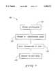
- FIG. 7is a flow diagram depicting a methodology in accordance with the invention.
- This inventionconcerns wireless communication, and specifically radio frequency (RF) data communication systems and is particularly concerned with systems which include a plurality of radio frequency (RF) identification devices of the type described below.
- the inventioncan be implemented in connection with a RF data communication system which is described in U.S. patent application Ser. No. 08/705,043, entitled “Radio Frequency Data Communications Device", filed Aug. 29, 1996, and naming James O'Toole, John R. Tuttle, Mark E. Tuttle, Tyler Lowrey, Kevin Devereaux, George Pax, Brian Higgins, Shu-Sun Yu, David Ovard, and Robert Rotzoll as inventors.
- the disclosure of U.S. patent application Ser. No. 08/705,043is expressly incorporated by reference herein.
- This inventioncan also be implemented in connection with a communication system which is described in U.S. Pat. No. 5,842,118, incorporated herein by reference.
- FIG. 1illustrates a radio frequency data communication device 12 at least a portion of which embodies the invention.
- the radio frequency data communication device 12includes an integrated circuit 16, a power source 18 connected to the integrated circuit 16 to supply power to the integrated circuit 16, and at least one antenna 14 connected to the integrated circuit 16 for radio frequency transmission and reception by the integrated circuit 16.
- integrated circuitshall be defined as a combination of interconnected circuit elements inseparably associated on or within a continuous substrate.
- the term “semiconductive substrate”is defined to mean any construction comprising semiconductive material, including, but not limited to, bulk semiconductive materials such as a semiconductive wafer (either alone or in assemblies comprising other materials thereon), and semiconductive material layers (either alone or in assemblies comprising other materials).
- substraterefers to any supporting structure, including, but not limited to, the semiconductive substrates described above.
- the integrated circuit 16is a monolithic integrated circuit.
- the term "monolithic integrated circuit”shall be defined as an integrated circuit wherein all circuit components are manufactured into or on top of a single chip of silicon.
- the integrated circuit 16will be described in greater detail below.
- the power source 18is a battery or other suitable power source.
- the radio frequency data communication device 12can be included in any appropriate housing or packaging.
- FIG. 2shows but one example in the form of an employee identification badge 10 including the radio frequency data communication device 12, and a card 11 made of plastic or other suitable material.
- the radio frequency data communication device 12is laminated to the back face of the plastic card 11, and the card forms the visible portion of the badge.
- the radio frequency data communication device 12is bonded to the back face of the card by embedding it within a thin bond line of epoxy-based material.
- the radio frequency data communication device 12is embedded into the plastic card 11.
- the front face of the badge 10has visual identification features including an employee photograph as well as identifying text.
- FIG. 3illustrates but one alternative housing supporting the device 12. More particularly, FIG. 3 shows a miniature housing 20 encasing the device 12 to define a tag which can be supported by an object (e.g., hung from an object, affixed to an object, etc.).
- the housing 20preferably has the general shape and size, in plan view, of a postage stamp.
- the embodiment of FIG. 3also includes a card 21 supporting the device 12 in the housing 20.
- the card 21is formed of plastic or other suitable material having a thickness of about 0.040 inches, a width of about 1.25 inches, and a height of about 1.25 inches.
- the device 12is bonded to a back face of the card 21 with a thin layer of non-conductive epoxy material that cooperates with the card to define the housing 20.
- the device 12can be included in any appropriate housing.
- the device 12is of a small size that lends itself to applications employing small housings, such as cards, miniature tags, etc. Larger housings can also be employed.
- the device 12, housed in any appropriate housingcan be supported from or attached to an object in any desired manner; for example using double sided tape, glue, lanyards, leash, nails, staples, rivets, or any other fastener.
- the housingcan be sewn on to an object, hung from an object, implanted in an object (hidden), etc.
- the integrated circuit 16includes a receiver 30 and a transmitter 32 (FIG. 5). In one embodiment, separate antennas 44 and 46 are provided for receiver and transmitter of the integrated circuit 16. In another embodiment (FIG. 1), a single antenna is shared by the receiver and transmitter sections. In one embodiment, the antenna is defined by conductive epoxy screened onto a card or housing. In the illustrated embodiment, the antenna is conductively bonded to the integrated circuit via bonding pads.
- that single antennapreferably comprises a folded dipole antenna defining a continuous conductive path, or loop, of microstrip.
- the antennacan be constructed as a continuous loop antenna.
- the batterycan take any suitable form.
- the battery typewill be selected depending on weight, size, and life requirements for a particular application.
- the battery 18is a thin profile button-type cell forming a small, thin energy cell more commonly utilized in watches and small electronic devices requiring a thin profile.
- a conventional button-type cellhas a pair of electrodes, an anode formed by one face and a cathode formed by an opposite face.
- Exemplary button-type cellsare disclosed in several pending U.S patent applications including U.S. patent application Ser. No. 08/205,957, "Button-Type Battery Having Bendable Construction and Angled Button-Type Battery," listing Mark E. Tuttle and Peter M.
- the battery 18comprises a series connected pair of button type cells.
- any suitable power sourcecan be employed.
- FIG. 4illustrates a radio frequency communication system 24 including the device 12 and a radio frequency interrogator unit (hereinafter "interrogator") 26.
- the device 12transmits and receives radio frequency communications to and from the interrogator 26.
- the interrogator unit 26includes an antenna 28, as well as dedicated transmitting and receiving circuitry, similar to that implemented on the integrated circuit 16.
- the system 24further includes a host computer 48 in communication with the interrogator 26.
- the host computer 48acts as a master in a master-slave relationship with the interrogator 26.
- the host computer 48includes an applications program for controlling the interrogator 26 and interpreting responses, and a library (“MRL”) of radio frequency identification device applications or functions. Most of the functions communicate with the interrogator 26.
- MTLlibrary
- the interrogator 26includes an antenna 28, and transmits an interrogation signal or command 27 ("forward link") via the antenna 28.
- the device 12receives the incoming interrogation signal via its antenna 14.
- the device 12responds by generating and transmitting a responsive signal or reply 29 ("return link").
- the responsive signal 29is encoded with information that uniquely identifies, or labels the particular device 12 that is transmitting, so as to identify any object or person with which the device 12 is associated.
- FIG. 4illustrates the device 12 as being in the housing 20 of FIG. 3.
- the system 24would operate in a similar manner if the device 12 is provided in a housing such as the housing 10 of FIG. 2, or any other appropriate housing.
- Multiple devices 12can be used in the same field of an interrogator 26 (i.e.) within communications range of an interrogator 26).
- multiple interrogators 26can be in proximity to one or more of the devices 12.
- An exemplary communication system which employs a plurality of RF identification devicesis shown in FIG. 6. There, individual devices are designated at 12 12a, 12b, . . . 12z (collectively "devices 12"). It will be understood that any number of devices 12 can be used in connection with system 24.
- the above described system 24is advantageous over prior art devices that utilize magnetic field effect systems because, with the system 24, a greater range can be achieved, and more information can be obtained (instead of just an identification number).
- such a system 24can be used, for example, to monitor large warehouse inventories having many unique products needing individual discrimination to determine the presence of particular items within a large lot of tagged products.
- the systemcan also be used to counteract terrorism to monitor luggage entering a plane to ensure that each item of luggage that enters the plane is owned by a passenger who actually boards the plane.
- Such a techniqueassumes that a terrorist will not board a plane that he or she is planning to bomb.
- the system 24is useful whenever RF transmission over a large range is desirable, such as for inventory control.
- the sensitivity of the devices 12is adjustable so that only devices within a certain range of the interrogator 26 will respond.
- the power of the interrogator 26is adjustable so that only devices within a certain range of the interrogator 26 will respond.
- the devices 12switch between a "sleep" mode of operation, and higher power modes to conserve energy and extend battery life during periods of time where no interrogation signal 27 is received by the device 12. These power conservation techniques are described in greater detail below.
- the receiver sensitivity of the device 12is tuned over a range of tuned and detuned states in order to modify the ability of the device to detect signal 27, and therefore adjust the tendency for the device to wake up.
- One way to adjust the receiver sensitivityis by adjusting the sensitivity, or impedance of the antenna. Another way is by controlling the gain of amplifiers included in the receiver. Another way is to adjust or switch in different circuit elements in the device 12, thereby realizing different circuit configurations.
- the transmitting sensitivity for the device 12can be adjusted. For example, transmitting range can be adjusted by controlling interrogator continuous wave power if the transmitter is operating in backscatter mode, and by controlling output power if the transmitter is in active mode.
- FIG. 5is a high level circuit schematic of the integrated circuit 16 utilized in the devices of FIGS. 1-4.
- the integrated circuit 16is a monolithic integrated circuit. More particularly, in the illustrated embodiment, the integrated circuit 16 comprises a single die, having a size of 209 ⁇ 116 mils 2 , including the receiver 30, the transmitter 32, a micro controller or microprocessor 34, a wake up timer and logic circuit 36, a clock recovery and data recovery circuit 38, and a bias voltage and current generator 42.
- a spread spectrum processing circuit 40is also included in the integrated circuit 16 and formed relative to the single die.
- signals received by the receiver 30are modulated spread spectrum signals.
- Spread spectrum modulationis described below.
- the modulation scheme for replies sent by the transmitter 32is selectable.
- One of the available selections for replies sent by the transmitter 32is modulated spread spectrum.
- the spread spectrum modulation technique employed in the illustrated embodimentrequires a transmission bandwidth that is up to several orders of magnitude greater than the minimum required signal bandwidth.
- spread spectrum modulation techniquesare bandwidth inefficient in single user applications, they are advantageous where there are multiple users, as is the case with the instant radio frequency identification system 24.
- the spread spectrum modulation technique of the illustrated embodimentis advantageous because the interrogator signal can be distinguished from other signals (e.g., radar, microwave ovens, etc.) operating at the same frequency.
- the spread spectrum signals transmitted by the device 12 and by the interrogator 26(FIG. 4) are pseudo random and have noise-like properties when compared with the digital command or reply.
- the spreading waveformis controlled by a pseudo-noise or pseudo random number (PN) sequence or code (described below).
- PN codeis a binary sequence that appears random but can be reproduced in a predetermined manner by the device 12. More particularly, incoming spread spectrum signals are demodulated by the device 12 through cross correlation with a version of the pseudo random carrier that is generated by the device 12 itself. Cross correlation with the correct PN sequence unspreads the spread spectrum signal and restores the modulated message in the same narrow band as the original data.
- a pseudo-noise or pseudo random sequenceis a binary sequence with an autocorrelation that resembles, over a period, the autocorrelation of a random binary sequence.
- the autocorrelation of a pseudo-noise sequencealso roughly resembles the autocorrelation of band-limited white noise.
- a pseudo-noise sequencehas many characteristics that are similar to those of random binary sequences. For example, a pseudo-noise sequence has a nearly equal number of zeros and ones, very low correlation between shifted versions of the sequence, and very low cross correlation between any two sequences.
- a pseudo-noise sequenceis usually generated using sequential logic circuits. For example, a pseudo-noise sequence can be generated using a feedback shift register.
- a feedback shift registercomprises consecutive stages of two state memory devices, and feedback logic. Binary sequences are shifted through the shift registers in response to clock pulses, and the output of the various stages are logically combined and fed back as the input to the first stage. The initial contents of the memory stages and the feedback logic circuit determine the successive contents of the memory.
- the illustrated embodimentemploys direct sequence spread spectrum modulation.
- a direct sequence spread spectrum (DSSS) systemspreads the baseband data by directly multiplying the baseband data pulses with a pseudo-noise sequence that is produced by a pseudo-noise generator.
- a single pulse or symbol of the PN waveformis called a "chip.”
- Synchronized data symbolswhich may be information bits or binary channel code symbols, are added in modulo-2 fashion to the chips before being modulated.
- the receiverperforms demodulation.
- the datais phase modulated, and the receiver performs coherent or differentially coherent phase-shift keying (PSK) demodulation.
- PSKphase-shift keying
- the datais amplitude modulated. Assuming that code synchronization has been achieved at the receiver, the received signal passes through a wideband filter and is multiplied by a local replica of the PN code sequence. This multiplication yields the unspread signal.
- a pseudo-noise sequenceis usually an odd number of chips long.
- one bit of datais represented by a thirty-one chip sequence.
- a zero bit of datais represented by inverting the pseudo-noise sequence.
- the system disclosed in U.S. patent application Ser. No. 08/092,147includes two receivers, a low power receiver for detecting a wake up signal from an interrogator, and a high power receiver for receiving commands from an interrogator.
- the integrated circuit 16 of the illustrated embodimentemploys a single receiver for both wake up and receiving commands from an interrogator. Another difference is that in the system 12 of the illustrated embodiment the receiver, not the interrogator, controls wake up.
- the integrated circuit 16includes a timer that causes the receiver and support circuitry to be powered on periodically. This is described in greater detail elsewhere.
- the interrogatorsends out a command that is spread around a certain center frequency (e.g, 2.44 GHz). After the interrogator transmits the command, and is expecting a response, the interrogator switches to a CW mode (continuous wave mode). In the continuous wave mode, the interrogator does not transmit any information. Instead, the interrogator just transmits 2.44 GHz radiation. In other words, the signal transmitted by the interrogator is not modulated. After the device 12 receives the command from the interrogator, the device 12 processes the command. If the device 12 is in a backscatter mode it alternately reflects or does not reflect the signal from the interrogator to send its reply.
- a certain center frequencye.g, 2.44 GHz
- frequency hoppingdoes not occur when the interrogator transmits a command, but occurs when the interrogator is in the continuous wave mode.
- the interrogatorin the continuous wave mode, hops between various frequencies close to the 2.44 GHz frequency. These various frequencies are sufficiently close to the 2.44 GHz frequency that backscatter antenna reflection characteristics of the device 12 are not appreciably altered. Because the interrogator is hopping between frequencies, the interrogator knows what frequency backscatter reflections to expect back from the device 12. By hopping between various frequencies, the amount of time the interrogator continuously uses a single frequency is reduced. This is advantageous in view of FCC regulatory requirements.
- the integrated circuit 16is formed according to semiconductor wafer processing steps, such as CMOS semiconductor wafer processing steps used to form static random access memories.
- the integrated circuit 16is a single metal integrated circuit
- the integrated circuit 16is formed using a single metal layer processing method. More particularly, only one layer of metal (e.g., aluminum) is employed. This is advantageous in that it results in a lower cost of production.
- a p-type waferis employed.
- the processing method employedprovides n-well areas used to define p-channel transistors; an active area which is used to define p+ and n+ diffused regions inside the p-type wafer or inside the n-well areas.
- a layeris provided that helps prevent leakage between adjacent devices.
- transistorare defined by forming n-type and p-type polysilicon.
- a contact layeris defined for connecting desired intersections of polysilicon with metal (aluminum) that is subsequently formed.
- the contact layeris also used, in some instances, for connecting desired intersections of the metal that is subsequently formed with active area.
- the metal layeris formed.
- the contact layerprovides a means for connecting metal with layers below the metal. Then, a passivation step is performed. Passivation means that the die is covered with a protective layer and holes are cut around the edge of the die so that electrical connection can be made to the bond pads.
- an insulating layeris provided, and another layer of aluminum is formed above the insulating layer. Holes are provided at selected locations to interconnect the top layer of aluminum with lower layers.
- the process of the preferred embodimentemploys only one layer of metal, and is therefore a relatively simple, inexpensive process.
- the device 12can operate over a wide range of carrier frequencies.
- the device 12can operate with carriers of 915-5800 MHZ.
- the device 12can operate with carrier frequencies in the 915, 2450, or 5800 MHZ bands.
- the antennasare half wave antennas, and frequency selectivity of the device 12 is achieved based on selection of the antenna external to the integrated circuit 16.
- Capacitors employed in the Schottky diode detectorare also selected based on the carrier frequency that will be employed.
- Active transmittersare known in the art. See, for example, U.S. patent application Ser. No. 08/281,384.
- U.S. patent application Ser. No. 08/281,384also discloses how transmit frequency for the transmitter 32 is recovered from a message received via radio frequency from the interrogator 26.
- the device 12differs from the device disclosed in U.S. patent application Ser. No. 08/281,384 in that a VCO control voltage is stored as an analog voltage level on a capacitor instead of as a digital number in a register.
- the recovered frequencyis also used by the integrated circuit 16 to generate a DPSK subcarrier for modulated backscatter transmission.
- the transmitteris capable of transmitting using different modulation schemes, and the modulation scheme is selectable by the interrogator. More particularly, if it is desired to change the modulation scheme, the interrogator sends an appropriate command via radio frequency.
- the transmittercan switch between multiple available modulation schemes such as Binary Phase Shift Keying (BPSK), Direct Sequence Spread Spectrum, On-Off Keying (OOK), and Modulated Backscatter (MBS).
- BPSKBinary Phase Shift Keying
- OOKOn-Off Keying
- MBSModulated Backscatter
- the integrated circuit 16includes the wake up timer and logic circuit 36 for conserving battery power. More particularly, the integrated circuit 16 normally operates in a sleep mode wherein most circuitry is inactive and there is a very low current draw on the battery 18.
- One circuit that is active during the sleep modeis a timer for waking up the integrated circuit at predetermined intervals. In the illustrated embodiment, the interval is 16 milliseconds; however, various other intervals can be selected by radio frequency by sending a message from the interrogator 26 to the device 12. For example, in the illustrated embodiment, the interval is selectable as being 0.5, 16, 64 or 256 milliseconds.
- the wake up timer and logic circuit 36activates the receiver 30, the clock recovery and data recovery circuit 38, and all the bias currents and voltages associated with the receiver 30. Such bias currents and voltages are generated by the bias voltage and current generator 42.
- the receiver 30determines if there is a radio frequency signal present.
- the wake up timer and logic circuit 36deactivates the receiver 30 and clock recovery and data recovery circuit 38. The receiver then goes back to sleep in the low current mode until another 16 milliseconds pass (or whatever sleep period is selected).
- the receiverwill unspread the spread spectrum signal for processing. It is possible that while the receiver is on, it may detect a radio frequency signal from a source other than the interrogator 26. For example, other radio frequency transmitting devices may be operating in the area. In the illustrated embodiment, the receiver is set to receive microwave frequency signals, so that a small antenna can be used. Therefore, the wake up timer and logic circuit 36 performs tests to determine if a radio frequency signal received on wake up is valid. If the wake up timer and logic circuit 36 determines that the incoming signal is not valid, the integrated circuit 16 returns to the sleep mode. The illustrated integrated circuit 16 consumes approximately one micro amp in the sleep mode, and the battery 18 is expected to last up to 10 years with a current drain of that order, depending on how often radio frequency signals are present and on the capacity of the battery.
- the integrated circuit 16If the incoming signal does not pass these tests, the integrated circuit 16 returns to the sleep mode. If the incoming signal does pass these tests, then the wake up timer and logic circuit determines whether the clock recovery and data recovery circuit 38 locks on to the clock frequency contained in the chip rate of the incoming signal within a predetermined time period. If frequency lock is obtained, the microprocessor is turned on for processing of the received command.
- the integrated circuit 16If frequency lock is not obtained within the predetermined time, the integrated circuit 16 returns to the sleep mode.
- the integrated circuit 16After the wake up timer and logic circuit 36 determines that a received signal is valid, the integrated circuit 16 then performs clock recovery. To save space and cost, the preferred device 12 does not include a crystal timing element (clock). Instead, all timing for the device 12 is extracted from valid incoming signals received by the receiver 30.
- clockcrystal timing element
- a valid incoming radio frequency signalis digital, and starts with a preamble, which is followed by a start code (or Barker code), which is followed by data (e.g., a command).
- a start codeor Barker code
- datae.g., a command
- the preambleis a long (e.g., eighteen milliseconds) string of zeros; i.e., the thirty-one chip sequence is inverted, and sent repeatedly for approximately 18 milliseconds.
- the data or command after the Barker codeis shorter than the preamble, and is approximately 4 milliseconds long.
- a crystalis employed to generate a clock.
- a crystalprovides a more stable, reliable clock to generate the transmit frequency, but also increases cost and size of the device 12.
- the clock recovery and data recovery circuit 38In addition to recovering a clock, the clock recovery and data recovery circuit 38 also performs data recovery on valid incoming signals.
- the valid spread spectrum incoming signalis passed through the spread spectrum processing circuit 40, and the spread spectrum processing circuit 40 extracts the actual ones and zeros of data from the incoming signal. More particularly, the spread spectrum processing circuit 40 takes the chips from the spread spectrum signal, and reduces each thirty-one chip section down to a bit of one or zero, which is passed to the micro controller 34.
- the integrated circuit 16includes unalterable indicia (a signature), different from the device's identification number discussed above.
- the unalterable indiciais burned into programmable read only memory or formed using a laser operating on fusible links.
- the unalterable indiciais indicative of the history of the particular die used to manufacture the integrated circuit 16.
- the unalterable indiciaincludes a lot number, wafer number, and die number of the die used to manufacture the integrated circuit 16. This information is transmitted by the transmitter in response to a manufacturer's command received by the receiver.
- the manufacturer's commandis a controlled access, or secret command that is not readily ascertainable by the public or purchaser/user of the device.
- This unalterable indiciacan be used to trace manufacturing problems in defective devices 12, or to locate stolen products carrying a device 12.
- the datais not differentially encoded.
- One rateis 9.5375 Mchips/sec (high band) and another rate is 4,768750 Mchips/sec (low band).
- the Barker codeis defined by the following bit string: 1111 1001 1010 1. Other embodiments are possible.
- the high data bandhas an effective data rate (adjusting for PN and ECC) of 189.3 Kbps.
- the low data bandhas an effective data rate of 94.68 Kbps.
- a 16-bit check sumis provided to detect bit errors on the packet level.
- a device 12can be programmed to either return a reply if a bad check sum is found in the forward link, or to simply halt execution and send no replies.
- a 16 bit CRCis employed in the forward link, the return link, or both, instead of or in addition to the check sum.
- the physical communications protocol for communications from the device 12 to the interrogator 26is referred to as the "return link" protocol.
- the return link messagesare sent in the following order:
- the interrogatorAfter sending a command, the interrogator sends a continuous unmodulated RF signal with a frequency of 2.44175 Ghz.
- Return link datais Differential Phase Shift Key (DPSK) modulated onto a square wave subcarrier with a frequency of 596.1 Khz.
- a data 0corresponds 11 to one phase and data 1 corresponds to another, shifted 180 degrees from the first phase.
- the subcarrieris used to modulate antenna impedance of a device 12.
- a switch between the two halves of the dipole antennais opened and closed. When the switch is closed, the antenna becomes the electrical equivalent of a single half-wavelength antenna that reflects a portion of the power being transmitted by the interrogator.
- the antennaWhen the switch is open, the antenna becomes the electrical equivalent of two quarter-wavelength antennas that reflect very little of the power transmitted by the interrogator.
- the switch driving a printed half wavelength dipole antennagives a typical range of 15 feet when the interrogator 26 transmits at 30 dBm into a 6 dB gain antenna.
- the preamble for the return linkincludes 2000 bits, alternating 2 zeros then 2 ones, etc., and a 13-bit start (Barker) code. Alternative preambles are possible.
- the start code or Barker Codeis defined by the following bit string: 1111 1001 1010 1.
- the reply link datais grouped in 13 bit words. Each word is composed of 8 data bits (D7, D6, D5, D4, D3, D2, D1, D0) and 5 ECC bits (P4, P3, P2, P1, P0).
- the Block Encoded Sequenceis D7, D6, D5, D4, D3, D2, D1, D0, P4, P3, P2, P1, P0.
- the bit durationis 6.71 ⁇ s making the effective data rate 91.75 Kbps for the return link.
- a 16-bit check sumis provided to detect bit errors on the packet level.
- a 16 bit CRCis employed in addition to or instead of the check sum.
- Each pair of data wordsis interleaved, starting with the Barker code and the first data word.
- the transmitted bit order for two sequential words, A and Bis D7A, D7B, D6A, D6B, D5A, D5B, D4A, D4B, D3A, D3B, D2A, D2B, D1A, D1B, D0A, D0B, P4A, P4B, P3A, P3B, P2A, P2B, P1A, P1B, P0A, P0B.
- D7Ais the first transmitted bit.
- DPSKis applied to the interleaved data.
- the interrogator 26may not able to interpret any of these replies. Further, there may be multiple interrogators in an area trying to interrogate the same device 12.
- arbitration schemesare provided.
- the interrogator 26sends a command causing each device 12 of a potentially large number of responding devices 12 to select a random number from a known range and use it as that device's arbitration number.
- the interrogator 26determines the arbitration number of every responder station capable of communicating at the same time. Therefore, the interrogator 26 is able to conduct subsequent uninterrupted communication with devices 12, one at a time, by addressing only one device 12.
- the interrogator 26can specify that a response is requested only from the device 12 with that identification number. Arbitration schemes are discussed below in greater detail.
- the arbitration of multiple interrogators per device 12is a detection method based upon each interrogator using a unique interrogator ID (InterrId).
- the Interrldis sent to a device 12 in a command.
- the device 12also stores an interrogator ID TagStoredInterrId.
- the TagStoredInterrIdis only updated by a WriteTagRegsXXX command.
- a RcvdInterrIdis included in replies from a device 12. If a TagStoredInterrId does not match the RcvdInterrId then the tag will not respond with a reply.
- the arbitration of more than one tag per interrogator 26is accomplished by using an ArbitrationValue and an ArbitrationMask during an Identify command. Contained within each device 12 is a random value ID (RandomValueLd) and an arbitration lockout (IDENTIFY -- LOCKOUT) bit.
- the RandomValueLdis set to a "random" binary number upon command by an interrogator. It may also be set by an Identify command setting a SELECT -- RANDOM -- VALUE bit in SubCmnd.
- the following examplesuse a 1-byte ArbitrationValue for simplicity. If an interrogator 26 transmits an Identify command with its ArbitrationMask set to 0000 0000 (binary), all devices 12 in the receiving range will respond. If there is only one device 12, communications may proceed between the interrogator 26 and device 12. If there are multiple devices 12 responding, the interrogator 26 will detect a collision and will start the arbitration sequence. To start the arbitration sequence among multiple tags, the interrogator 26 instructs the tags to clear their IDENTIFY -- LOCKOUT bit and (possibly) re-randomize their RandomValueLd values. The ArbitrationValue 0000 0000 and ArbitrationMask 0000 0001 are then transmitted to all devices 12 in range.
- the devices 12perform a logical ANDing (masking) of the ArbitrationMask and the RandomValueLd. If the result matches the ArbitrationValue sent by the interrogator 26, the device or devices 12 will reply to the Identify command. If not, the interrogator 26 will increment the ArbitrationValue to 0000 0001 and try again.
- the interrogator 26then checks each of the possible binary numbers (0000 0000 and 0000 0001 in this case) in the expanded mask (0000 0001) for a response by a device 12. If a single device 12 responds to one of these values, the interrogator 26 will reply by commanding it to set its lockout bit. If any collisions are detected at this mask level, the mask would be widened again by one bit, and so on through the eight bit wide mask (256 numbers). If no collisions are detected for a particular ArbitrationValue and ArbitrationMask combination, the TagId returned in the reply is used for direct communication with that particular device 12. During the arbitration sequence with up to about one hundred devices 12, the mask will eventually grow large enough such that all devices 12 can respond without collision. After the mask widens to four or five bits, more devices 12 have unique random numbers and single tag replies are received. Thus with each expansion of the ArbitrationMask, there are fewer and fewer tags left to Identify.
- the microcontrollerAfter the micro controller processes a command from the interrogator 26, the micro controller includes response circuitry which formats the reply as specified in the protocol and the formatted reply leaves the micro controller via a serial data port of the micro controller.
- the microcontrolleralso includes delay circuitry which is configured to delay transmission of an individual reply.
- the delay circuitrycomprises a random value generator which is effective to produce a delayed transmission from a respective one of devices 12, 12a-12z.
- Each individual device 12, 12a-12zpreferably includes its own random value generator.
- each responding devicein a multiple-response scenario, generates a random value whereupon logic circuitry on board each device masks a portion of the random value and uses the resulting product to calculate a delay.
- At least two delays from responding devices 12, 12a-12zare sufficiently different so as to decorrelate the response message in a manner which permits the interrogator 26 to detect an error.
- the delay aspect of the replyis discussed below in more detail in the "Time Delay Reply" section.
- the formatted replyis spread spectrum encoded by the spread spectrum processing circuit 40.
- the replyis then modulated by the transmitter 32.
- the transmitter 32is capable of transmitting using different modulation schemes, and the modulation scheme is selectable by the interrogator 26. More particularly, if it is desired to change the modulation scheme, the interrogator 26 sends an appropriate command via radio frequency.
- the transmitted replieshave a format similar to the format of incoming messages. More particularly, a reply starts with a preamble, followed by a Barker or start code which is thirteen bits long, followed by actual data.
- No stop bitsare included in the incoming message or reply, in the preferred embodiment. Instead, part of the incoming message describes how many bytes are included, so the integrated circuit 16 knows how much information is included. Similarly, part of the outgoing reply describes how many bytes are included, so the interrogator 26 knows how much information is included.
- the incoming message and outgoing replypreferably also include a check sum or redundancy code so that the integrated circuit 16 or the interrogator 26 can confirm receipt of the entire message or reply.
- the integrated circuit 16After the reply is sent, the integrated circuit 16 returns to the sleep mode, and the wake up timer and logic circuit 36 starts timing again for the next wake up (e.g., in 16 milliseconds, or whatever period is selected).
- arbitrationis provided in a wireless communication system.
- a wireless communication systemis an RF communication system and such arbitration is provided between a plurality of wireless RF identification devices 12, 12a-12z (FIG. 6).
- Suchis the case when, for example, more than one device attempts to reply to one or more interrogator(s).
- Preferred methodical steps of this aspect of the inventionare set forth in a high level flow chart appearing in FIG. 7 generally at 100.
- interrogator 26is provided.
- interrogator 26is configured for transmitting and receiving RF communication data as described in U.S. patent application Ser. No. 08/705,043, incorporated by reference above. More than one interrogator can be provided.
- at least one, and preferably a plurality of RF identification devices, such as devices 12, 12a-12z (FIG. 6)are provided.
- such devicesinclude integrated circuitry which is configured for receiving RF communication data transmitted by interrogator 26. Responsive to receiving the RF communication data from interrogator 26, the communication devices preferably perform an operation directed to determining which devices need to reply to the interrogator.
- each reply by an individual device 12is delayed, at step 130, for a determinable amount of time.
- at least some of the determinable amounts of timeare different. Accordingly, at least some of the resulting delays are different.
- individual devices 12include delay circuitry which calculates their own individual delays.
- such calculated delaysare used to define amounts of time which are different as between those responding or transmitting devices 12.
- a random valueis generated and incorporated into the determinable amount of time which is utilized to delay a reply for a particular respective transmitting device 12. According to another aspect, the random value is used to calculate the determinable amount of time.
- each device 12includes a random value generator supplied by hardware contained by each device 12.
- the random value generatorcan be contained in integrated circuit 16 or separately provided.
- Each random value generatorreturns an 8-bit random value. Accordingly, such gives 2 8 different numbers which could be used for the delay.
- Such random valueis then masked such that the upper-most significant bits are dropped. Preferably, the three least significant bit are left. This ensures that the calculated delay will be 0-7 times a predetermined delay value.
- a numerical 1is added to the masked random value to give a masked random value sum and to address wrap around concerns. The masked random value sum is then multiplied by the predetermined delay value.
- the predetermined delay valueis given by BitTime/8, where "BitTime” is defined as the time required to send one bit from the device 12 to the interrogator 24.
- Other predetermined delay valuesare possible such as various multiples of "BitTime”.
- the inventionprovides for individual identification device replies to be corrupted in a manner which permits the interrogator to detect a collision in the event of multiple device replies and to take appropriate action in response thereto.
- corruptionconstitutes incorporating a transmission delay in a reply which is different from a transmission delay which is incorporated for at least one other responding or transmitting device 12.
- the above-described methodologyenables the interrogator to more precisely and accurately detect a collision between multiple replies. Such is accomplished, in the preferred embodiment, by incorporating the delay into the beginning of a reply message from an individual device 12. Initially, after the delay is calculated and in accordance with "return link" protocol, a message including a preamble, a Barker code, a reply packet, and a check sum are sent to the interrogator. Once received and suitably processed by the interrogator, the interrogator compares the check sum which was returned with the check sum which was originally sent. If the check sums match, then there was no collision and further interrogator processing continues.
- An exemplary post-collision processingmay change the ArbitrationMask and/or ArbitrationValue and re-execute the Identify command.
- the device 12includes an active transponder, instead of a transponder which relies on magnetic coupling for power, the device 12 has a much greater range.
- One application for devices 12is inventory control to determine the presence of particular items within a large lot of products.
- EASelectronic article surveillance
- the devices 12can be attached to retail items in a store having an interrogator 26 at the exits, for detection of unauthorized removal of retail items.
- the merchantcan deactivate or remove devices 12 from retail items for which proper payment has been made.
- Another application for devices 12is to track migration of animals.
- Another application for devices 12is to counteract terrorism by monitoring luggage entering a plane to ensure that each item of luggage that enters the plane is owned by a passenger who actually boards the plane.
- the devices 12can also be used to monitor luggage to locate lost luggage.
- the device 12can be use to track packages, such as courier packages.
- the device 12can be used to track hazardous chemicals or waste to ensure that it safely reaches a proper disposal site.
- the device 12can be used for security purposes, to track personnel within a building.
- the device 12can also be used for access control.
- the device 12can be used to monitor and manage freight transit.
- interrogators 26can be placed at the entrance and exit of a terminal (e.g., a rail or truck terminal), to monitor incoming and outgoing shipments of vehicles bearing the devices 12.
- the device 12can be used to impede car theft.
- a European anti-theft directive(74/61/EEC) provides that all new car models sold after January 1997 must be fitted with electronic immobilizers and approved alarm systems.
- the devices 12can be provided on keychains or within car keys, and interrogators 26 placed in cars, so that the vehicle will be inoperable unless the specified device 12 for a specific car is used.
- the interrogator 26can control the door locks of a car, or the ignition of the car, or both. Because the device 12 includes memory, the interrogator 26 in the car can periodically automatically change values in the device 12 (like changing a password).
- Devices 12can be placed in cars and used in connection with electronic toll collections systems. Because the devices 12 can be used to identify the respective cars in which they are placed, interrogators 26 in toll plazas can charge appropriate accounts based on which cars have passed the toll plaza.
- Devices 12can be placed in cars and used in connection with parking systems. Because the devices 12 can be used to identify the respective cars in which they are placed, interrogators 26 in parking areas can determine when a vehicle arrives and leaves a parking area.
- the devices 12can be used for inventory control of rental equipment.
- the devices 12can be used where bar code labels will not properly work because of harsh environmental conditions (e.g., grease, dirt, paint).
Landscapes
- Engineering & Computer Science (AREA)
- Radar, Positioning & Navigation (AREA)
- Remote Sensing (AREA)
- Physics & Mathematics (AREA)
- General Physics & Mathematics (AREA)
- Computer Networks & Wireless Communication (AREA)
- Theoretical Computer Science (AREA)
- Toxicology (AREA)
- Artificial Intelligence (AREA)
- Computer Vision & Pattern Recognition (AREA)
- Health & Medical Sciences (AREA)
- Electromagnetism (AREA)
- General Health & Medical Sciences (AREA)
- Business, Economics & Management (AREA)
- Finance (AREA)
- Mobile Radio Communication Systems (AREA)
Abstract
Description
P0=(D1+D2+D5+D7) modulo 2
P1=[(D1+D3+D4+D6) modulo 2] Complement
P2=(D0+D2+D3+D6+D7) modulo 2
P3=[(D0+D4+D5+D6+D7) modulo 2] Complement
P4=(D0+D1+D2+D3+D4+D5) modulo 2.
P0=(D1+D2+D5+D7) modulo 2
P1=[(D1+D3+D4+D6) modulo 2] Complement
P2=(D0+D2+D3+D6+D7) modulo 2
P3=[(D0+D4+D5+D6+D7) modulo 2] Complement
P4=(D0+D1+D2+D3+D4+D5) modulo 2.
Claims (27)
Priority Applications (4)
| Application Number | Priority Date | Filing Date | Title |
|---|---|---|---|
| US08/769,653US6104333A (en) | 1996-12-19 | 1996-12-19 | Methods of processing wireless communication, methods of processing radio frequency communication, and related systems |
| PCT/US1997/022928WO1998027441A1 (en) | 1996-12-19 | 1997-12-12 | Methods of processing wireless communication, methods of processing radio frequency communication, and related systems |
| AU53815/98AAU5381598A (en) | 1996-12-19 | 1997-12-12 | Methods of processing wireless communication, methods of processing radio frequency communication, and related systems |
| US09/602,849US6265963B1 (en) | 1996-12-19 | 2000-06-23 | Methods of processing wireless communication, methods of processing radio frequency communication, and related systems |
Applications Claiming Priority (1)
| Application Number | Priority Date | Filing Date | Title |
|---|---|---|---|
| US08/769,653US6104333A (en) | 1996-12-19 | 1996-12-19 | Methods of processing wireless communication, methods of processing radio frequency communication, and related systems |
Related Child Applications (1)
| Application Number | Title | Priority Date | Filing Date |
|---|---|---|---|
| US09/602,849ContinuationUS6265963B1 (en) | 1996-12-19 | 2000-06-23 | Methods of processing wireless communication, methods of processing radio frequency communication, and related systems |
Publications (1)
| Publication Number | Publication Date |
|---|---|
| US6104333Atrue US6104333A (en) | 2000-08-15 |
Family
ID=25086127
Family Applications (2)
| Application Number | Title | Priority Date | Filing Date |
|---|---|---|---|
| US08/769,653Expired - LifetimeUS6104333A (en) | 1996-12-19 | 1996-12-19 | Methods of processing wireless communication, methods of processing radio frequency communication, and related systems |
| US09/602,849Expired - LifetimeUS6265963B1 (en) | 1996-12-19 | 2000-06-23 | Methods of processing wireless communication, methods of processing radio frequency communication, and related systems |
Family Applications After (1)
| Application Number | Title | Priority Date | Filing Date |
|---|---|---|---|
| US09/602,849Expired - LifetimeUS6265963B1 (en) | 1996-12-19 | 2000-06-23 | Methods of processing wireless communication, methods of processing radio frequency communication, and related systems |
Country Status (3)
| Country | Link |
|---|---|
| US (2) | US6104333A (en) |
| AU (1) | AU5381598A (en) |
| WO (1) | WO1998027441A1 (en) |
Cited By (89)
| Publication number | Priority date | Publication date | Assignee | Title |
|---|---|---|---|---|
| US6229443B1 (en)* | 2000-06-23 | 2001-05-08 | Single Chip Systems | Apparatus and method for detuning of RFID tag to regulate voltage |
| US20010014090A1 (en)* | 1998-02-19 | 2001-08-16 | Wood Clifton W. | Method of addressing messages and communications system |
| US6282186B1 (en) | 1998-02-19 | 2001-08-28 | Micron Technology, Inc. | Method of addressing messages and communications system |
| US6286763B1 (en)* | 1999-09-21 | 2001-09-11 | Intermac Ip Corp. | Method and apparatus to automatically search data carriers, such as RFID tags and machine-readable symbols |
| US6286762B1 (en)* | 1999-09-21 | 2001-09-11 | Intermec Ip Corp. | Method and apparatus to perform a predefined search on data carriers, such as RFID tags |
| US6307847B1 (en)* | 1998-02-19 | 2001-10-23 | Micron Technology, Inc. | Method of addressing messages and communications systems |
| US6307848B1 (en) | 1998-02-19 | 2001-10-23 | Micron Technology, Inc. | Method of addressing messages, method of establishing wireless communications, and communications system |
| US6318636B1 (en)* | 1999-09-21 | 2001-11-20 | Intermec Ip Corp. | Method and apparatus to read different types of data carriers, such RFID tags and machine-readable symbols, and a user interface for the same |
| US20020002035A1 (en)* | 2000-06-28 | 2002-01-03 | Samsung Electronics Co., Ltd | Headset having a short-range mobile system |
| US6356738B1 (en)* | 1999-02-18 | 2002-03-12 | Gary W. Schneider | Method and apparatus for communicating data with a transponder |
| US20020045454A1 (en)* | 2000-10-17 | 2002-04-18 | Nec Corporation | Radio communication connection destination specifying method |
| US6421540B1 (en)* | 1997-05-30 | 2002-07-16 | Qualcomm Incorporated | Method and apparatus for maximizing standby time using a quick paging channel |
| US20020097178A1 (en)* | 2001-01-19 | 2002-07-25 | Thomas Warren J. | System and method to attribute, reconcile and account for automated vehicle identification charges irrespective of vehicle ownership |
| US20020097282A1 (en)* | 1999-02-04 | 2002-07-25 | Intermec Ip Corp. | Method and apparatus for automatic tax verification |
| US20020111702A1 (en)* | 2001-02-15 | 2002-08-15 | Angel Jeffrey R. | Factory personnel monitors |
| US20020120676A1 (en)* | 2001-02-23 | 2002-08-29 | Biondi James W. | Network monitoring systems for medical devices |
| US20020154607A1 (en)* | 2001-02-13 | 2002-10-24 | Nokia Corporation | Short range RF network configuration |
| US20030052161A1 (en)* | 2001-09-18 | 2003-03-20 | Rakers Patrick L. | Method of communication in a radio frequency identification system |
| US6563423B2 (en)* | 2001-03-01 | 2003-05-13 | International Business Machines Corporation | Location tracking of individuals in physical spaces |
| US20030097304A1 (en)* | 2001-11-16 | 2003-05-22 | Hunt Douglas Harold | Automated unmanned rental system and method |
| US20030112155A1 (en)* | 2000-06-24 | 2003-06-19 | Martin Landre | Method for tracking waste |
| WO2003081787A3 (en)* | 2002-03-26 | 2003-12-24 | Nokia Corp | Radio frequency identification (rf-id) based discovery for short range radio communication |
| US6707376B1 (en)* | 2002-08-09 | 2004-03-16 | Sensormatic Electronics Corporation | Pulsed power method for increased read range for a radio frequency identification reader |
| US20040145515A1 (en)* | 2001-05-23 | 2004-07-29 | Hall Charles D | Transmit-receive module for a radar |
| US20040169582A1 (en)* | 2002-12-24 | 2004-09-02 | Yoichi Endo | Semiconductor device |
| US20040176032A1 (en)* | 2002-03-26 | 2004-09-09 | Sakari Kotola | Radio frequency identification (RF-ID) based discovery for short range radio communication with reader device having transponder functionality |
| US20040201495A1 (en)* | 2003-04-11 | 2004-10-14 | Hee Chuan Lim | Digital coded horizontal overhead obstacles warning system for vehicles |
| US20050057341A1 (en)* | 2003-09-17 | 2005-03-17 | Roesner Bruce B. | Deep sleep in an RFID tag |
| US20050093374A1 (en)* | 2003-10-31 | 2005-05-05 | Timothy Connors | Controlling power supplied to a circuit using an externally applied magnetic field |
| US20050099302A1 (en)* | 2003-11-10 | 2005-05-12 | Lieffort Seth A. | System for detecting radio-frequency identification tags |
| US20050099298A1 (en)* | 2003-11-10 | 2005-05-12 | Mercer Thomas C. | Algorithm for RFID security |
| US20050121526A1 (en)* | 2003-12-09 | 2005-06-09 | Intelleflex Corporation | Battery activation circuit |
| US20050154572A1 (en)* | 2004-01-14 | 2005-07-14 | Sweeney Patrick J.Ii | Radio frequency identification simulator and tester |
| US20050154570A1 (en)* | 2004-01-14 | 2005-07-14 | Alysis Interactive Corporation | Radio frequency identification simulator |
| US20050169219A1 (en)* | 2004-01-30 | 2005-08-04 | Mark Serpa | Method and system for peer-to-peer wireless communication over unlicensed communication spectrum |
| US20050280539A1 (en)* | 2004-06-22 | 2005-12-22 | Pettus Michael G | RFID system utilizing parametric reflective technology |
| US6987752B1 (en)* | 1999-09-15 | 2006-01-17 | Lucent Technologies Inc. | Method and apparatus for frequency offset estimation and interleaver synchronization using periodic signature sequences |
| US20060055539A1 (en)* | 2004-09-09 | 2006-03-16 | Lawrence Daniel P | Antennas for radio frequency identification tags in the form of a logo, brand name, trademark, or the like |
| US20060087406A1 (en)* | 2004-10-26 | 2006-04-27 | Willins Bruce A | System and method for identifying an RFID reader |
| US20060232383A1 (en)* | 2005-04-15 | 2006-10-19 | Samsung Electronics Co., Ltd. | RFID tag and RFID reader for anti-collision and operating method thereof |
| US20060244592A1 (en)* | 2005-04-29 | 2006-11-02 | Ilkka Kansala | Indicating radio frequency identification (RF-ID) tag |
| US20060250220A1 (en)* | 2005-05-06 | 2006-11-09 | Intelleflex Corporation | Accurate persistent nodes |
| US20060255131A1 (en)* | 2005-05-11 | 2006-11-16 | Intelleflex Corporation | Smart tag activation |
| US20060280149A1 (en)* | 2003-07-22 | 2006-12-14 | Carmen Kuhl | Reader device for radio frequency identification transponder with transponder functionality |
| US20070018794A1 (en)* | 2005-07-20 | 2007-01-25 | Intelleflex Corporation | Selective RF device activation |
| US20070086371A1 (en)* | 2005-10-17 | 2007-04-19 | Telefonaktiebolaget Lm Ericsson | Controlled multi-user packet detection for a wireless packet data channel |
| US20070103274A1 (en)* | 2005-04-13 | 2007-05-10 | Oliver Berthold | Radio frequency identification (RFID) system that meets data protection requirements through owner-controlled RFID tag functionality |
| US7221257B1 (en)* | 1997-08-20 | 2007-05-22 | Micron Technology, Inc. | Wireless communication devices, radio frequency identification devices, methods of forming a wireless communication device, and methods of forming a radio frequency identification device |
| US20070136036A1 (en)* | 2005-12-08 | 2007-06-14 | Sweeney Patrick J Ii | Radio frequency identification system deployer |
| US20070141983A1 (en)* | 2005-12-15 | 2007-06-21 | Intelleflex Corporation | Clock-free activation circuit |
| US20070236350A1 (en)* | 2004-01-23 | 2007-10-11 | Sebastian Nystrom | Method, Device and System for Automated Context Information Based Selective Data Provision by Identification Means |
| US20070252696A1 (en)* | 2006-05-01 | 2007-11-01 | Belisle Timothy F | Geo-location system, method and apparatus |
| US20070295817A1 (en)* | 2006-06-22 | 2007-12-27 | Intermec Ip Corp. | Automatic data collection apparatus and method for variable focus using a deformable mirror |
| US20080018431A1 (en)* | 2004-02-06 | 2008-01-24 | Turner Christopher G G | Rfid Group Selection Method |
| US20080023552A1 (en)* | 2006-07-28 | 2008-01-31 | Intermec Ip Corp. | Enhanced resolution automatic data collection apparatus and method using an afocal optical element |
| US20080180221A1 (en)* | 2007-01-30 | 2008-07-31 | Micron Technology, Inc. | Systems and methods for RFID tag arbitration |
| US20080231428A1 (en)* | 2004-03-17 | 2008-09-25 | Carmen Kuhl | Continuous Data a Provision by Radio Frequency Identification (rfid) Transponders |
| US20080297324A1 (en)* | 2007-05-30 | 2008-12-04 | Micron Technology, Inc. | Methods and systems of receiving data payload of rfid tags |
| US7463893B1 (en)* | 2000-09-22 | 2008-12-09 | Sirf Technology, Inc. | Method and apparatus for implementing a GPS receiver on a single integrated circuit |
| US20090005004A1 (en)* | 2000-05-05 | 2009-01-01 | Nokia Corporation | Communication devices and method of communication |
| US20090002129A1 (en)* | 2006-01-12 | 2009-01-01 | Kwang-Yoon Shin | Method of Preventing Collisions Between Rfid Readers in Rfid System |
| US20090127337A1 (en)* | 2007-11-21 | 2009-05-21 | Infineon Technologies Ag | Identification of contactless cards |
| US7588185B2 (en) | 2001-06-07 | 2009-09-15 | 3M Innovative Properties Company | RFID data collection and use |
| US7619529B2 (en)* | 1998-08-14 | 2009-11-17 | 3M Innovative Properties Company | Application for a radio frequency identification system |
| US20100148937A1 (en)* | 2008-12-17 | 2010-06-17 | Barry Howard | System and Method of Tracking Salvaged Vehicles and Parts Using RFID Tags |
| US20100277284A1 (en)* | 2009-05-01 | 2010-11-04 | Brown Jonathan E | Data separation in high density environments |
| US20100277283A1 (en)* | 2009-05-01 | 2010-11-04 | Burkart Scott M | Systems and methods for RFID tag operation |
| US20100277286A1 (en)* | 2009-05-01 | 2010-11-04 | Burkart Scott M | Synchronization of devices in a RFID communications environment |
| US20110009075A1 (en)* | 2009-07-07 | 2011-01-13 | Nokia Corporation | Data transfer with wirelessly powered communication devices |
| US20110059692A1 (en)* | 2009-09-08 | 2011-03-10 | Electronics And Telecommunications Research Institute | Communications device using near field |
| US20110087756A1 (en)* | 2009-10-13 | 2011-04-14 | Cardiopulmonary Corporation | Method and Apparatus for Displaying Data from Medical Devices |
| US8115635B2 (en) | 2005-02-08 | 2012-02-14 | Abbott Diabetes Care Inc. | RF tag on test strips, test strip vials and boxes |
| US8144014B1 (en) | 2008-02-22 | 2012-03-27 | Wg Security Products | Infrared electronic article surveillance system with dynamic passcode protection |
| USRE43382E1 (en) | 1998-02-19 | 2012-05-15 | Round Rock Research, Llc | Method of addressing messages and communications systems |
| DE102004013885B4 (en)* | 2004-03-16 | 2012-08-30 | Atmel Automotive Gmbh | Method and modulation control device for wireless data transmission |
| US20150169018A1 (en)* | 2012-07-03 | 2015-06-18 | Kapsch Trafficcom Ab | On board unit with power management |
| US9084116B2 (en) | 2004-03-19 | 2015-07-14 | Nokia Technologies Oy | Detector logic and radio identification device and method for enhancing terminal operations |
| US9088058B2 (en) | 2009-08-19 | 2015-07-21 | Vubiq Networks, Inc. | Waveguide interface with a launch transducer and a circular interface plate |
| US20150281811A1 (en)* | 2000-12-15 | 2015-10-01 | Apple Inc. | Personal items network, and associated methods |
| US9318017B2 (en) | 1999-05-26 | 2016-04-19 | Visteon Global Technologies, Inc. | Wireless control system and method |
| US9370041B2 (en)* | 1999-05-26 | 2016-06-14 | Visteon Global Technologies, Inc. | Wireless communications system and method |
| US9380474B2 (en) | 2013-03-08 | 2016-06-28 | Cardiopulmonary Corp. | Network monitoring for active medical device alarms |
| US9454745B2 (en) | 2008-12-17 | 2016-09-27 | Alli Solutions, Inc. | System and method of tracking vehicles within a parking lot using RFID tags |
| US9740894B1 (en)* | 2016-06-13 | 2017-08-22 | Motorola Mobility Llc | Silent RFID state and restore back |
| US10320047B2 (en) | 2009-08-19 | 2019-06-11 | Vubiq Networks, Inc. | Waveguide assembly comprising a molded waveguide interface having a support block for a launch transducer that is coupled to a communication device through a flange attached to the interface |
| US10650201B1 (en)* | 2011-08-02 | 2020-05-12 | Impinj, Inc. | RFID tags with port-dependent functionality |
| US10818997B2 (en) | 2017-12-29 | 2020-10-27 | Vubiq Networks, Inc. | Waveguide interface and printed circuit board launch transducer assembly and methods of use thereof |
| US11216625B2 (en) | 2018-12-05 | 2022-01-04 | Vubiq Networks, Inc. | High bit density millimeter wave RFID systems, devices, and methods of use thereof |
| CN115862352A (en)* | 2022-11-24 | 2023-03-28 | 浙江欧菲克斯交通科技有限公司 | Computing method, system, medium and device for solving parallel code sending conflict by random number |
Families Citing this family (55)
| Publication number | Priority date | Publication date | Assignee | Title |
|---|---|---|---|---|
| US6250192B1 (en) | 1996-11-12 | 2001-06-26 | Micron Technology, Inc. | Method for sawing wafers employing multiple indexing techniques for multiple die dimensions |
| US6493934B2 (en) | 1996-11-12 | 2002-12-17 | Salman Akram | Method for sawing wafers employing multiple indexing techniques for multiple die dimensions |
| ES2169612T3 (en)* | 1998-07-21 | 2002-07-01 | Koninkl Philips Electronics Nv | SYSTEM FOR DATA TRANSMISSION FROM A DATA CARRIER TO A STATION THROUGH AT LEAST ANOTHER AUXILIARY CARRIER SIGNAL. |
| GB2342251A (en)* | 1998-09-29 | 2000-04-05 | Secr Defence | Proximity measuring apparatus |
| US6535109B1 (en)* | 1998-12-01 | 2003-03-18 | Texas Instruments Sensors And Controls, Inc. | System and method for communicating with multiple transponders |
| US6615408B1 (en) | 1999-01-15 | 2003-09-02 | Grischa Corporation | Method, system, and apparatus for providing action selections to an image referencing a product in a video production |
| US6424993B1 (en) | 1999-05-26 | 2002-07-23 | Respondtv, Inc. | Method, apparatus, and computer program product for server bandwidth utilization management |
| DE19938898C1 (en)* | 1999-08-17 | 2001-04-05 | Siemens Ag | Device for authorization identification and triggering / releasing an action, in particular electronic locking device for motor vehicles, and base unit and key unit for realizing such a device |
| WO2001025571A1 (en)* | 1999-10-04 | 2001-04-12 | Siemens Automotive Corporation | Sequencing control for vehicle access system |
| US6377203B1 (en) | 2000-02-01 | 2002-04-23 | 3M Innovative Properties Company | Collision arbitration method and apparatus for reading multiple radio frequency identification tags |
| US7259654B2 (en) | 2000-02-28 | 2007-08-21 | Magellan Technology Pty Limited | Radio frequency identification transponder |
| US7248145B2 (en) | 2000-02-28 | 2007-07-24 | Magellan Technology Oty Limited | Radio frequency identification transponder |
| AUPQ589400A0 (en)* | 2000-02-28 | 2000-03-23 | Magellan Technology Pty Limited | Rfid transponders |
| US7962414B1 (en) | 2000-05-11 | 2011-06-14 | Thomson Licensing | Method and system for controlling and auditing content/service systems |
| US6329944B1 (en)* | 2000-05-12 | 2001-12-11 | Northrop Grumman Corporation | Tag communication protocol & system |
| US6763315B2 (en) | 2000-11-29 | 2004-07-13 | Ensure Technologies, Inc. | Method of securing access to a user having an enhanced security proximity token |
| US6989750B2 (en)* | 2001-02-12 | 2006-01-24 | Symbol Technologies, Inc. | Radio frequency identification architecture |
| US7925535B2 (en)* | 2001-07-10 | 2011-04-12 | American Express Travel Related Services Company, Inc. | System and method for securing RF transactions using a radio frequency identification device including a random number generator |
| GB0122163D0 (en)* | 2001-09-13 | 2001-10-31 | Tagtec Ltd | Wireless communication system |
| US6951305B2 (en)* | 2001-11-21 | 2005-10-04 | Goliath Solutions, Llc. | Advertising compliance monitoring system |
| US7374096B2 (en) | 2001-11-21 | 2008-05-20 | Goliath Solutions, Llc | Advertising compliance monitoring system |
| US6837427B2 (en)* | 2001-11-21 | 2005-01-04 | Goliath Solutions, Llc. | Advertising compliance monitoring system |
| US7269745B2 (en)* | 2002-06-06 | 2007-09-11 | Sony Computer Entertainment Inc. | Methods and apparatus for composing an identification number |
| US20040046642A1 (en)* | 2002-09-05 | 2004-03-11 | Honeywell International Inc. | Protocol for addressing groups of RFID tags |
| US6726099B2 (en) | 2002-09-05 | 2004-04-27 | Honeywell International Inc. | RFID tag having multiple transceivers |
| US7239229B2 (en)* | 2002-09-05 | 2007-07-03 | Honeywell International Inc. | Efficient protocol for reading RFID tags |
| US7573370B2 (en)* | 2002-09-05 | 2009-08-11 | Honeywell International Inc. | Method and device for storing and distributing information in an RFID tag |
| US7044387B2 (en)* | 2002-09-05 | 2006-05-16 | Honeywell International Inc. | RFID tag and communication protocol for long range tag communications and power efficiency |
| US6747555B2 (en) | 2002-09-24 | 2004-06-08 | International Business Machines Corporation | Tracking apparatus and associated method for a radio frequency enabled reminder system |
| JP3979246B2 (en)* | 2002-09-30 | 2007-09-19 | ブラザー工業株式会社 | Communication system interrogator and interrogator |
| GB2395626B (en)* | 2002-11-21 | 2006-05-10 | Hewlett Packard Co | A memory tag and a reader |
| DE10301146B4 (en)* | 2003-01-14 | 2014-07-10 | Robert Bosch Gmbh | A security system |
| US7627091B2 (en)* | 2003-06-25 | 2009-12-01 | Avaya Inc. | Universal emergency number ELIN based on network address ranges |
| US20060108421A1 (en)* | 2003-12-03 | 2006-05-25 | Becker Robert C | RFID tag having multiple transceivers |
| US7130385B1 (en) | 2004-03-05 | 2006-10-31 | Avaya Technology Corp. | Advanced port-based E911 strategy for IP telephony |
| US7030786B2 (en)* | 2004-05-24 | 2006-04-18 | Impinj, Inc. | RFID readers and RFID tags communicating using extensible bit vectors |
| US7246746B2 (en)* | 2004-08-03 | 2007-07-24 | Avaya Technology Corp. | Integrated real-time automated location positioning asset management system |
| US7536188B1 (en) | 2004-09-01 | 2009-05-19 | Avaya Inc. | Communication device locating system |
| KR100657903B1 (en)* | 2004-10-15 | 2006-12-14 | 삼성전기주식회사 | Tag collision prevention method and tag system for same |
| US7589616B2 (en)* | 2005-01-20 | 2009-09-15 | Avaya Inc. | Mobile devices including RFID tag readers |
| US20060176179A1 (en)* | 2005-01-26 | 2006-08-10 | Battelle Memorial Institute | Bendable, active radio-frequency sensor tags and a system of same |
| US8107625B2 (en)* | 2005-03-31 | 2012-01-31 | Avaya Inc. | IP phone intruder security monitoring system |
| US7425888B2 (en)* | 2005-07-29 | 2008-09-16 | Symbol Technologies, Inc. | Methods for optimizing communications between an RFID reader and a tag population using non-sequential masking |
| KR100701617B1 (en)* | 2005-09-08 | 2007-03-30 | 삼성전자주식회사 | Method and apparatus for collecting data |
| US7821386B1 (en) | 2005-10-11 | 2010-10-26 | Avaya Inc. | Departure-based reminder systems |
| DE102006010159A1 (en)* | 2006-02-27 | 2007-09-06 | GTI Gesellschaft für technische Informatik GmbH | Electronic label and method for monitoring good |
| US7310070B1 (en) | 2006-08-23 | 2007-12-18 | Goliath Solutions, Llc | Radio frequency identification shelf antenna with a distributed pattern for localized tag detection |
| DE112006003955A5 (en)* | 2006-10-20 | 2009-04-16 | Siemens Aktiengesellschaft | Transponder with readout protection and related process |
| EP2031566B1 (en)* | 2007-09-03 | 2014-07-02 | Burg-Wächter Kg | Method for operating a system with at least one electronic lock |
| US20100060424A1 (en)* | 2008-03-19 | 2010-03-11 | Checkpoint Systems, Inc. | Range Extension and Multiple Access in Modulated Backscatter Systems |
| WO2010009493A1 (en) | 2008-07-21 | 2010-01-28 | Magellan Technology Pty Ltd | A device having data storage |
| US9232055B2 (en)* | 2008-12-23 | 2016-01-05 | Avaya Inc. | SIP presence based notifications |
| US20130046153A1 (en) | 2011-08-16 | 2013-02-21 | Elwha LLC, a limited liability company of the State of Delaware | Systematic distillation of status data relating to regimen compliance |
| SE538455C2 (en)* | 2014-04-01 | 2016-07-12 | Great Innovations Stockholm Ab | A photographic target detection system and method as well as a position detection apparatus and a transponder therefore |
| SE538020C2 (en)* | 2014-04-01 | 2016-02-09 | Utvecklingsavdelningen I Sverige Ab | Method, system, transponder and a position detection device for an accurate measurement of a position |
Citations (36)
| Publication number | Priority date | Publication date | Assignee | Title |
|---|---|---|---|---|
| US3911396A (en)* | 1972-12-26 | 1975-10-07 | Mitsubishi Electric Corp | Data transmission system |
| US4075632A (en)* | 1974-08-27 | 1978-02-21 | The United States Of America As Represented By The United States Department Of Energy | Interrogation, and detection system |
| US4492961A (en)* | 1980-03-13 | 1985-01-08 | International Standard Electric Corporation | System for deriving precise instants of triggering of a pulsed device |
| US4691202A (en)* | 1984-04-03 | 1987-09-01 | Denne Phillip R M | Identification systems |
| US4857893A (en)* | 1986-07-18 | 1989-08-15 | Bi Inc. | Single chip transponder device |
| US4926182A (en)* | 1986-05-30 | 1990-05-15 | Sharp Kabushiki Kaisha | Microwave data transmission apparatus |
| EP0427342A1 (en)* | 1989-11-10 | 1991-05-15 | Koninklijke Philips Electronics N.V. | Transmission system |
| US5055659A (en)* | 1990-02-06 | 1991-10-08 | Amtech Technology Corp. | High speed system for reading and writing data from and into remote tags |
| EP0467036A2 (en)* | 1990-06-15 | 1992-01-22 | Savi Technology, Inc. | Method and apparatus for radio identification and tracking |
| US5121407A (en)* | 1990-09-27 | 1992-06-09 | Pittway Corporation | Spread spectrum communications system |
| US5134085A (en)* | 1991-11-21 | 1992-07-28 | Micron Technology, Inc. | Reduced-mask, split-polysilicon CMOS process, incorporating stacked-capacitor cells, for fabricating multi-megabit dynamic random access memories |
| GB2259227A (en)* | 1991-08-30 | 1993-03-03 | Marconi Gec Ltd | Improvements in or relating to transponders |
| US5258762A (en)* | 1989-02-27 | 1993-11-02 | Philippe Cabon | Identification system using hertzian waves, consisting of an interrogation station and a responder unit |
| US5266925A (en)* | 1991-09-30 | 1993-11-30 | Westinghouse Electric Corp. | Electronic identification tag interrogation method |
| US5272367A (en)* | 1988-05-02 | 1993-12-21 | Micron Technology, Inc. | Fabrication of complementary n-channel and p-channel circuits (ICs) useful in the manufacture of dynamic random access memories (drams) |
| WO1993025918A1 (en)* | 1992-06-17 | 1993-12-23 | Saab-Scania Combitech Aktiebolag | A system for the transfer of information comprising several transponders |
| EP0585132A1 (en)* | 1992-08-26 | 1994-03-02 | Btg International Limited | Synchronised electronic identification system |
| US5305008A (en)* | 1991-08-12 | 1994-04-19 | Integrated Silicon Design Pty. Ltd. | Transponder system |
| US5365551A (en)* | 1992-12-15 | 1994-11-15 | Micron Technology, Inc. | Data communication transceiver using identification protocol |
| US5390360A (en)* | 1991-12-23 | 1995-02-14 | Motorola, Inc. | R.F. communication system interrogation apparatus and method |
| US5430441A (en)* | 1993-10-12 | 1995-07-04 | Motorola, Inc. | Transponding tag and method |
| US5432027A (en)* | 1994-03-02 | 1995-07-11 | Micron Communications, Inc. | Button-type battery having bendable construction, and angled button-type battery |
| US5489546A (en)* | 1995-05-24 | 1996-02-06 | Micron Technology, Inc. | Method of forming CMOS devices using independent thickness spacers in a split-polysilicon DRAM process |
| US5494495A (en)* | 1994-10-11 | 1996-02-27 | Micron Communications, Inc. | Method of forming button-type batteries |
| EP0702324A2 (en)* | 1994-09-12 | 1996-03-20 | International Business Machines Corporation | Multiple item radio frequency tag identification protocol |
| US5523749A (en)* | 1991-04-03 | 1996-06-04 | Integrated Silicon Design Pty. Ltd. | Identification system for simultaneously interrogated labels |
| US5537105A (en)* | 1991-01-04 | 1996-07-16 | British Technology Group Limited | Electronic identification system |
| US5539775A (en)* | 1993-03-17 | 1996-07-23 | Micron Technology, Inc. | Modulated spread spectrum in RF identification systems method |
| US5552772A (en)* | 1993-12-20 | 1996-09-03 | Trimble Navigation Limited | Location of emergency service workers |
| US5568512A (en)* | 1994-07-27 | 1996-10-22 | Micron Communications, Inc. | Communication system having transmitter frequency control |
| US5621412A (en)* | 1994-04-26 | 1997-04-15 | Texas Instruments Incorporated | Multi-stage transponder wake-up, method and structure |
| US5646607A (en)* | 1990-06-15 | 1997-07-08 | Texas Instruments Incorporated | Transponder/interrogator protocol in a multi-interrogator field |
| US5649296A (en)* | 1995-06-19 | 1997-07-15 | Lucent Technologies Inc. | Full duplex modulated backscatter system |
| US5751570A (en)* | 1995-07-19 | 1998-05-12 | Anatoli Stobbe | Method of automatically identifying an unknown number of transponders with a reader and identification system for executing the method |
| US5790946A (en)* | 1993-07-15 | 1998-08-04 | Rotzoll; Robert R. | Wake up device for a communications system |
| US5842118A (en)* | 1996-12-18 | 1998-11-24 | Micron Communications, Inc. | Communication system including diversity antenna queuing |
Family Cites Families (4)
| Publication number | Priority date | Publication date | Assignee | Title |
|---|---|---|---|---|
| US5497140A (en) | 1992-08-12 | 1996-03-05 | Micron Technology, Inc. | Electrically powered postage stamp or mailing or shipping label operative with radio frequency (RF) communication |
| DE4345610B4 (en) | 1992-06-17 | 2013-01-03 | Micron Technology Inc. | Method for producing a radio-frequency identification device (HFID) |
| US5406263A (en) | 1992-07-27 | 1995-04-11 | Micron Communications, Inc. | Anti-theft method for detecting the unauthorized opening of containers and baggage |
| JP2991776B2 (en) | 1994-12-01 | 1999-12-20 | マイクロン、コミュニケーションズ、インコーポレーテッド | Method of manufacturing button type battery and gasket for insulating and sealing button type battery |
- 1996
- 1996-12-19USUS08/769,653patent/US6104333A/ennot_activeExpired - Lifetime
- 1997
- 1997-12-12WOPCT/US1997/022928patent/WO1998027441A1/enactiveApplication Filing
- 1997-12-12AUAU53815/98Apatent/AU5381598A/ennot_activeAbandoned
- 2000
- 2000-06-23USUS09/602,849patent/US6265963B1/ennot_activeExpired - Lifetime
Patent Citations (36)
| Publication number | Priority date | Publication date | Assignee | Title |
|---|---|---|---|---|
| US3911396A (en)* | 1972-12-26 | 1975-10-07 | Mitsubishi Electric Corp | Data transmission system |
| US4075632A (en)* | 1974-08-27 | 1978-02-21 | The United States Of America As Represented By The United States Department Of Energy | Interrogation, and detection system |
| US4492961A (en)* | 1980-03-13 | 1985-01-08 | International Standard Electric Corporation | System for deriving precise instants of triggering of a pulsed device |
| US4691202A (en)* | 1984-04-03 | 1987-09-01 | Denne Phillip R M | Identification systems |
| US4926182A (en)* | 1986-05-30 | 1990-05-15 | Sharp Kabushiki Kaisha | Microwave data transmission apparatus |
| US4857893A (en)* | 1986-07-18 | 1989-08-15 | Bi Inc. | Single chip transponder device |
| US5272367A (en)* | 1988-05-02 | 1993-12-21 | Micron Technology, Inc. | Fabrication of complementary n-channel and p-channel circuits (ICs) useful in the manufacture of dynamic random access memories (drams) |
| US5258762A (en)* | 1989-02-27 | 1993-11-02 | Philippe Cabon | Identification system using hertzian waves, consisting of an interrogation station and a responder unit |
| EP0427342A1 (en)* | 1989-11-10 | 1991-05-15 | Koninklijke Philips Electronics N.V. | Transmission system |
| US5055659A (en)* | 1990-02-06 | 1991-10-08 | Amtech Technology Corp. | High speed system for reading and writing data from and into remote tags |
| EP0467036A2 (en)* | 1990-06-15 | 1992-01-22 | Savi Technology, Inc. | Method and apparatus for radio identification and tracking |
| US5646607A (en)* | 1990-06-15 | 1997-07-08 | Texas Instruments Incorporated | Transponder/interrogator protocol in a multi-interrogator field |
| US5121407A (en)* | 1990-09-27 | 1992-06-09 | Pittway Corporation | Spread spectrum communications system |
| US5537105A (en)* | 1991-01-04 | 1996-07-16 | British Technology Group Limited | Electronic identification system |
| US5523749A (en)* | 1991-04-03 | 1996-06-04 | Integrated Silicon Design Pty. Ltd. | Identification system for simultaneously interrogated labels |
| US5305008A (en)* | 1991-08-12 | 1994-04-19 | Integrated Silicon Design Pty. Ltd. | Transponder system |
| GB2259227A (en)* | 1991-08-30 | 1993-03-03 | Marconi Gec Ltd | Improvements in or relating to transponders |
| US5266925A (en)* | 1991-09-30 | 1993-11-30 | Westinghouse Electric Corp. | Electronic identification tag interrogation method |
| US5134085A (en)* | 1991-11-21 | 1992-07-28 | Micron Technology, Inc. | Reduced-mask, split-polysilicon CMOS process, incorporating stacked-capacitor cells, for fabricating multi-megabit dynamic random access memories |
| US5390360A (en)* | 1991-12-23 | 1995-02-14 | Motorola, Inc. | R.F. communication system interrogation apparatus and method |
| WO1993025918A1 (en)* | 1992-06-17 | 1993-12-23 | Saab-Scania Combitech Aktiebolag | A system for the transfer of information comprising several transponders |
| EP0585132A1 (en)* | 1992-08-26 | 1994-03-02 | Btg International Limited | Synchronised electronic identification system |
| US5365551A (en)* | 1992-12-15 | 1994-11-15 | Micron Technology, Inc. | Data communication transceiver using identification protocol |
| US5539775A (en)* | 1993-03-17 | 1996-07-23 | Micron Technology, Inc. | Modulated spread spectrum in RF identification systems method |
| US5790946A (en)* | 1993-07-15 | 1998-08-04 | Rotzoll; Robert R. | Wake up device for a communications system |
| US5430441A (en)* | 1993-10-12 | 1995-07-04 | Motorola, Inc. | Transponding tag and method |
| US5552772A (en)* | 1993-12-20 | 1996-09-03 | Trimble Navigation Limited | Location of emergency service workers |
| US5432027A (en)* | 1994-03-02 | 1995-07-11 | Micron Communications, Inc. | Button-type battery having bendable construction, and angled button-type battery |
| US5621412A (en)* | 1994-04-26 | 1997-04-15 | Texas Instruments Incorporated | Multi-stage transponder wake-up, method and structure |
| US5568512A (en)* | 1994-07-27 | 1996-10-22 | Micron Communications, Inc. | Communication system having transmitter frequency control |
| EP0702324A2 (en)* | 1994-09-12 | 1996-03-20 | International Business Machines Corporation | Multiple item radio frequency tag identification protocol |
| US5494495A (en)* | 1994-10-11 | 1996-02-27 | Micron Communications, Inc. | Method of forming button-type batteries |
| US5489546A (en)* | 1995-05-24 | 1996-02-06 | Micron Technology, Inc. | Method of forming CMOS devices using independent thickness spacers in a split-polysilicon DRAM process |
| US5649296A (en)* | 1995-06-19 | 1997-07-15 | Lucent Technologies Inc. | Full duplex modulated backscatter system |
| US5751570A (en)* | 1995-07-19 | 1998-05-12 | Anatoli Stobbe | Method of automatically identifying an unknown number of transponders with a reader and identification system for executing the method |
| US5842118A (en)* | 1996-12-18 | 1998-11-24 | Micron Communications, Inc. | Communication system including diversity antenna queuing |
Cited By (183)
| Publication number | Priority date | Publication date | Assignee | Title |
|---|---|---|---|---|
| US6421540B1 (en)* | 1997-05-30 | 2002-07-16 | Qualcomm Incorporated | Method and apparatus for maximizing standby time using a quick paging channel |
| US7221257B1 (en)* | 1997-08-20 | 2007-05-22 | Micron Technology, Inc. | Wireless communication devices, radio frequency identification devices, methods of forming a wireless communication device, and methods of forming a radio frequency identification device |
| US7639638B2 (en) | 1998-02-19 | 2009-12-29 | Keystone Technology Solutions, Llc | Method and apparatus for an arbitration scheme for radio frequency identification devices |
| US20090322491A1 (en)* | 1998-02-19 | 2009-12-31 | Keystone Technology Solutions, Llc | Method of Addressing Messages and Communications System |
| US8488581B2 (en) | 1998-02-19 | 2013-07-16 | Round Rock Research, Llc | Methods and apparatus for conducting financial transactions |
| US6307847B1 (en)* | 1998-02-19 | 2001-10-23 | Micron Technology, Inc. | Method of addressing messages and communications systems |
| US6307848B1 (en) | 1998-02-19 | 2001-10-23 | Micron Technology, Inc. | Method of addressing messages, method of establishing wireless communications, and communications system |
| US20080007412A1 (en)* | 1998-02-19 | 2008-01-10 | Wood Clifton W Jr | Method of Addressing Messages and Communications System |
| US7315522B2 (en) | 1998-02-19 | 2008-01-01 | Micron Technology, Inc. | Communication methods using slotted replies |
| USRE44411E1 (en) | 1998-02-19 | 2013-08-06 | Round Rock Research, Llc | Method of addressing messages, method of establishing wireless communications and communications system |
| US8634338B2 (en) | 1998-02-19 | 2014-01-21 | Round Rock Research, Llc | Methods and apparatus for conducting financial transactions |
| US6282186B1 (en) | 1998-02-19 | 2001-08-28 | Micron Technology, Inc. | Method of addressing messages and communications system |
| USRE42254E1 (en) | 1998-02-19 | 2011-03-29 | Round Rock Research, Llc | Method of addressing messages and communications system |
| US8638709B2 (en) | 1998-02-19 | 2014-01-28 | Round Rock Research, Llc | Methods and apparatus for conducting financial transactions |
| USRE43445E1 (en) | 1998-02-19 | 2012-06-05 | Round Rock Research, Llc | Method and apparatus to manage RFID tags |
| US20010014090A1 (en)* | 1998-02-19 | 2001-08-16 | Wood Clifton W. | Method of addressing messages and communications system |
| USRE43382E1 (en) | 1998-02-19 | 2012-05-15 | Round Rock Research, Llc | Method of addressing messages and communications systems |
| US9014077B2 (en) | 1998-02-19 | 2015-04-21 | Round Rock Research, Llc | Methods and apparatus for conducting financial transactions |
| US20080042806A1 (en)* | 1998-02-19 | 2008-02-21 | Wood Clifton W Jr | Method of Addressing Messages and Communications System |
| US8040829B2 (en) | 1998-02-19 | 2011-10-18 | Round Rock Research, Llc | Method of addressing messages and communications system |
| USRE40686E1 (en) | 1998-02-19 | 2009-03-31 | Keystone Technology Solutions, Llc | Method of addressing messages and communications system |
| US7672260B2 (en) | 1998-02-19 | 2010-03-02 | Keystone Technology Solutions, Llc | Method of addressing messages and communications system |
| USRE41352E1 (en) | 1998-02-19 | 2010-05-25 | Keystone Technology Solutions, Llc | Method of addressing messages and communications |
| US20060209781A1 (en)* | 1998-02-19 | 2006-09-21 | Micron Technology, Inc. | Method of addressing messages and communications system |
| USRE43254E1 (en)* | 1998-02-19 | 2012-03-20 | Round Rock Research, Llc | Method of addressing messages and communications systems |
| US20060056325A1 (en)* | 1998-02-19 | 2006-03-16 | Wood Clifton W Jr | Method of addressing messages and communications system |
| US7760677B2 (en) | 1998-02-19 | 2010-07-20 | Keystone Technology Solutions, Llc | Method of addressing messages and communications system |
| US20050207364A1 (en)* | 1998-02-19 | 2005-09-22 | Wood Clifton W Jr | Method of addressing messages and communications system |
| USRE41471E1 (en) | 1998-02-19 | 2010-08-03 | Round Rock Research, Llc | Method of Addressing Messages and Communications System |
| USRE43020E1 (en) | 1998-02-19 | 2011-12-13 | Round Rock Research, Llc | Method of addressing messages, method of establishing wireless communications, and communications system |
| USRE41530E1 (en) | 1998-02-19 | 2010-08-17 | Round Rock Research, Llc | Method and apparatus to select radio frequency identification devices in accordance with an arbitration scheme |
| US7936706B2 (en) | 1998-02-19 | 2011-05-03 | Round Rock Research, Llc | Method of addressing messages and communications system |
| USRE41531E1 (en) | 1998-02-19 | 2010-08-17 | Round Rock Research, Llc | Communications systems for radio frequency identification (RFID) |
| USRE42344E1 (en) | 1998-02-19 | 2011-05-10 | Round Rock Research, Llc | Method and apparatus to manage RFID tags |
| USRE42900E1 (en) | 1998-02-19 | 2011-11-08 | Round Rock Research, Llc | Method of addressing messages and communications systems |
| USRE42599E1 (en) | 1998-02-19 | 2011-08-09 | Round Rock Research, Llc | Method of addressing messages and communications system |
| US7619529B2 (en)* | 1998-08-14 | 2009-11-17 | 3M Innovative Properties Company | Application for a radio frequency identification system |
| US20020097282A1 (en)* | 1999-02-04 | 2002-07-25 | Intermec Ip Corp. | Method and apparatus for automatic tax verification |
| US6356738B1 (en)* | 1999-02-18 | 2002-03-12 | Gary W. Schneider | Method and apparatus for communicating data with a transponder |
| US9318017B2 (en) | 1999-05-26 | 2016-04-19 | Visteon Global Technologies, Inc. | Wireless control system and method |
| US9370041B2 (en)* | 1999-05-26 | 2016-06-14 | Visteon Global Technologies, Inc. | Wireless communications system and method |
| US6987752B1 (en)* | 1999-09-15 | 2006-01-17 | Lucent Technologies Inc. | Method and apparatus for frequency offset estimation and interleaver synchronization using periodic signature sequences |
| US6286763B1 (en)* | 1999-09-21 | 2001-09-11 | Intermac Ip Corp. | Method and apparatus to automatically search data carriers, such as RFID tags and machine-readable symbols |
| US6286762B1 (en)* | 1999-09-21 | 2001-09-11 | Intermec Ip Corp. | Method and apparatus to perform a predefined search on data carriers, such as RFID tags |
| US6318636B1 (en)* | 1999-09-21 | 2001-11-20 | Intermec Ip Corp. | Method and apparatus to read different types of data carriers, such RFID tags and machine-readable symbols, and a user interface for the same |
| US20090005004A1 (en)* | 2000-05-05 | 2009-01-01 | Nokia Corporation | Communication devices and method of communication |
| US8233881B2 (en) | 2000-05-05 | 2012-07-31 | Nokia Corporation | Communication devices and method of communication |
| US8391839B2 (en) | 2000-05-05 | 2013-03-05 | Nokia Corporation | Communication devices and method of communication |
| US6229443B1 (en)* | 2000-06-23 | 2001-05-08 | Single Chip Systems | Apparatus and method for detuning of RFID tag to regulate voltage |
| US20030112155A1 (en)* | 2000-06-24 | 2003-06-19 | Martin Landre | Method for tracking waste |
| US7035588B2 (en)* | 2000-06-28 | 2006-04-25 | Samsung Electronics Co., Ltd. | Headset having a short-range mobile system |
| US20020002035A1 (en)* | 2000-06-28 | 2002-01-03 | Samsung Electronics Co., Ltd | Headset having a short-range mobile system |
| US7463893B1 (en)* | 2000-09-22 | 2008-12-09 | Sirf Technology, Inc. | Method and apparatus for implementing a GPS receiver on a single integrated circuit |
| US6871047B2 (en)* | 2000-10-17 | 2005-03-22 | Nec Corporation | Radio communication connection destination specifying method |
| US20020045454A1 (en)* | 2000-10-17 | 2002-04-18 | Nec Corporation | Radio communication connection destination specifying method |
| US20150281811A1 (en)* | 2000-12-15 | 2015-10-01 | Apple Inc. | Personal items network, and associated methods |
| US20020097178A1 (en)* | 2001-01-19 | 2002-07-25 | Thomas Warren J. | System and method to attribute, reconcile and account for automated vehicle identification charges irrespective of vehicle ownership |
| US20020154607A1 (en)* | 2001-02-13 | 2002-10-24 | Nokia Corporation | Short range RF network configuration |
| US7200130B2 (en)* | 2001-02-13 | 2007-04-03 | Nokia Corporation | Short range RF network configuration |
| US20020111702A1 (en)* | 2001-02-15 | 2002-08-15 | Angel Jeffrey R. | Factory personnel monitors |
| US6839753B2 (en) | 2001-02-23 | 2005-01-04 | Cardiopulmonary Corporation | Network monitoring systems for medical devices |
| US20020120676A1 (en)* | 2001-02-23 | 2002-08-29 | Biondi James W. | Network monitoring systems for medical devices |
| US6563423B2 (en)* | 2001-03-01 | 2003-05-13 | International Business Machines Corporation | Location tracking of individuals in physical spaces |
| US7205934B2 (en) | 2001-05-23 | 2007-04-17 | Astrium Limited | Transmit-receive module for a radar |
| US20040145515A1 (en)* | 2001-05-23 | 2004-07-29 | Hall Charles D | Transmit-receive module for a radar |
| US7588185B2 (en) | 2001-06-07 | 2009-09-15 | 3M Innovative Properties Company | RFID data collection and use |
| US20030052161A1 (en)* | 2001-09-18 | 2003-03-20 | Rakers Patrick L. | Method of communication in a radio frequency identification system |
| US6763996B2 (en)* | 2001-09-18 | 2004-07-20 | Motorola, Inc. | Method of communication in a radio frequency identification system |
| US6708879B2 (en) | 2001-11-16 | 2004-03-23 | Audio Visual Services Corporation | Automated unmanned rental system and method |
| US20030097304A1 (en)* | 2001-11-16 | 2003-05-22 | Hunt Douglas Harold | Automated unmanned rental system and method |
| US20040176032A1 (en)* | 2002-03-26 | 2004-09-09 | Sakari Kotola | Radio frequency identification (RF-ID) based discovery for short range radio communication with reader device having transponder functionality |
| US7565108B2 (en) | 2002-03-26 | 2009-07-21 | Nokia Corporation | Radio frequency identification (RF-ID) based discovery for short range radio communication with reader device having transponder functionality |
| WO2003081787A3 (en)* | 2002-03-26 | 2003-12-24 | Nokia Corp | Radio frequency identification (rf-id) based discovery for short range radio communication |
| CN1643806B (en)* | 2002-03-26 | 2012-02-22 | 诺基亚公司 | Radio Frequency Identification (RF-ID)-Based Discovery for Near Field Communications |
| US6892052B2 (en) | 2002-03-26 | 2005-05-10 | Nokia Corporation | Radio frequency identification (RF-ID) based discovery for short range radio communication |
| WO2004015613A3 (en)* | 2002-08-09 | 2004-07-08 | Sensormatic Electronics Corp | Pulsed power method for increased read range for a radio frequency identification reader |
| AU2003269958B2 (en)* | 2002-08-09 | 2007-08-23 | Sensormatic Electronics Llc | Pulsed power method for increased read range for a radio frequency identification reader |
| US6707376B1 (en)* | 2002-08-09 | 2004-03-16 | Sensormatic Electronics Corporation | Pulsed power method for increased read range for a radio frequency identification reader |
| US20040169582A1 (en)* | 2002-12-24 | 2004-09-02 | Yoichi Endo | Semiconductor device |
| US7113072B2 (en)* | 2002-12-24 | 2006-09-26 | Seiko Instruments Inc. | Semiconductor device for keyless entry transmitter |
| US20040201495A1 (en)* | 2003-04-11 | 2004-10-14 | Hee Chuan Lim | Digital coded horizontal overhead obstacles warning system for vehicles |
| US9306637B2 (en) | 2003-07-22 | 2016-04-05 | Nokia Technologies Oy | Reader device for radio frequency identification transponder with transponder functionality |
| US8384519B2 (en) | 2003-07-22 | 2013-02-26 | Nokia Corporation | Reader device for radio frequency identification transponder with transponder functionality |
| US20060280149A1 (en)* | 2003-07-22 | 2006-12-14 | Carmen Kuhl | Reader device for radio frequency identification transponder with transponder functionality |
| US8823496B2 (en) | 2003-07-22 | 2014-09-02 | Nokia Corporation | Reader device for radio frequency identification transponder with transponder functionality |
| US7119664B2 (en)* | 2003-09-17 | 2006-10-10 | Id Solutions, Inc. | Deep sleep in an RFID tag |
| US20050057341A1 (en)* | 2003-09-17 | 2005-03-17 | Roesner Bruce B. | Deep sleep in an RFID tag |
| AU2004273936B2 (en)* | 2003-09-17 | 2008-07-24 | Mitac Information Technology Corporation | Deep sleep in an RFID tag |
| US20060289641A1 (en)* | 2003-09-17 | 2006-12-28 | Id Solutions, Inc. | Deep sleep in an RFID tag |
| WO2005029389A3 (en)* | 2003-09-17 | 2005-06-16 | Bella Id Solutions Inc | Deep sleep in an rfid tag |
| US7250695B2 (en)* | 2003-10-31 | 2007-07-31 | Hewlett-Packard Development Company, L.P. | Controlling power supplied to a circuit using an externally applied magnetic field |
| US20050093374A1 (en)* | 2003-10-31 | 2005-05-05 | Timothy Connors | Controlling power supplied to a circuit using an externally applied magnetic field |
| US7372364B2 (en) | 2003-11-10 | 2008-05-13 | 3M Innovative Properties Company | Algorithm for RFID security |
| US20070075836A1 (en)* | 2003-11-10 | 2007-04-05 | 3M Innovative Properties Company | System for detecting radio-frequency identification tags |
| US20050099298A1 (en)* | 2003-11-10 | 2005-05-12 | Mercer Thomas C. | Algorithm for RFID security |
| US20050099302A1 (en)* | 2003-11-10 | 2005-05-12 | Lieffort Seth A. | System for detecting radio-frequency identification tags |
| US7405663B2 (en) | 2003-11-10 | 2008-07-29 | 3M Innovative Properties Company | System for detecting radio-frequency identification tags |
| US7119692B2 (en) | 2003-11-10 | 2006-10-10 | 3M Innovative Properties Company | System for detecting radio-frequency identification tags |
| US20050121526A1 (en)* | 2003-12-09 | 2005-06-09 | Intelleflex Corporation | Battery activation circuit |
| US7612652B2 (en) | 2003-12-09 | 2009-11-03 | Intelleflex Corporation | Battery activation circuit |
| US20050154572A1 (en)* | 2004-01-14 | 2005-07-14 | Sweeney Patrick J.Ii | Radio frequency identification simulator and tester |
| US20050154570A1 (en)* | 2004-01-14 | 2005-07-14 | Alysis Interactive Corporation | Radio frequency identification simulator |
| US8725626B2 (en) | 2004-01-23 | 2014-05-13 | Nokia Corporation | Method, device and system for automated context information based selective data provision by identification means |
| US20070236350A1 (en)* | 2004-01-23 | 2007-10-11 | Sebastian Nystrom | Method, Device and System for Automated Context Information Based Selective Data Provision by Identification Means |
| US20050169219A1 (en)* | 2004-01-30 | 2005-08-04 | Mark Serpa | Method and system for peer-to-peer wireless communication over unlicensed communication spectrum |
| US7342895B2 (en) | 2004-01-30 | 2008-03-11 | Mark Serpa | Method and system for peer-to-peer wireless communication over unlicensed communication spectrum |
| US8981909B2 (en) | 2004-02-06 | 2015-03-17 | Zih Corp. | RFID group selection method |
| US20080018431A1 (en)* | 2004-02-06 | 2008-01-24 | Turner Christopher G G | Rfid Group Selection Method |
| DE102004013885B4 (en)* | 2004-03-16 | 2012-08-30 | Atmel Automotive Gmbh | Method and modulation control device for wireless data transmission |
| US8225014B2 (en) | 2004-03-17 | 2012-07-17 | Nokia Corporation | Continuous data provision by radio frequency identification (RFID) transponders |
| US20080231428A1 (en)* | 2004-03-17 | 2008-09-25 | Carmen Kuhl | Continuous Data a Provision by Radio Frequency Identification (rfid) Transponders |
| US10546164B2 (en) | 2004-03-19 | 2020-01-28 | Nokia Technologies Oy | Detector logic and radio identification device and method for enhancing terminal operations |
| US9881190B2 (en) | 2004-03-19 | 2018-01-30 | Nokia Technologies Oy | Detector logic and radio identification device and method for enhancing terminal operations |
| US9619682B2 (en) | 2004-03-19 | 2017-04-11 | Nokia Technologies Oy | Detector logic and radio identification device and method for enhancing terminal operations |
| US9084116B2 (en) | 2004-03-19 | 2015-07-14 | Nokia Technologies Oy | Detector logic and radio identification device and method for enhancing terminal operations |
| US7498940B2 (en)* | 2004-06-22 | 2009-03-03 | Vubiq, Inc. | RFID system utilizing parametric reradiated technology |
| US7460014B2 (en) | 2004-06-22 | 2008-12-02 | Vubiq Incorporated | RFID system utilizing parametric reflective technology |
| US20050280539A1 (en)* | 2004-06-22 | 2005-12-22 | Pettus Michael G | RFID system utilizing parametric reflective technology |
| US20050280504A1 (en)* | 2004-06-22 | 2005-12-22 | Vubiq Incorporated, A Nevada Corporation | RFID system utilizing parametric reflective technology |
| US20060055539A1 (en)* | 2004-09-09 | 2006-03-16 | Lawrence Daniel P | Antennas for radio frequency identification tags in the form of a logo, brand name, trademark, or the like |
| US20060087406A1 (en)* | 2004-10-26 | 2006-04-27 | Willins Bruce A | System and method for identifying an RFID reader |
| US8358210B2 (en) | 2005-02-08 | 2013-01-22 | Abbott Diabetes Care Inc. | RF tag on test strips, test strip vials and boxes |
| US8542122B2 (en) | 2005-02-08 | 2013-09-24 | Abbott Diabetes Care Inc. | Glucose measurement device and methods using RFID |
| US8115635B2 (en) | 2005-02-08 | 2012-02-14 | Abbott Diabetes Care Inc. | RF tag on test strips, test strip vials and boxes |
| US8390455B2 (en) | 2005-02-08 | 2013-03-05 | Abbott Diabetes Care Inc. | RF tag on test strips, test strip vials and boxes |
| US8223021B2 (en) | 2005-02-08 | 2012-07-17 | Abbott Diabetes Care Inc. | RF tag on test strips, test strip vials and boxes |
| US7786866B2 (en)* | 2005-04-13 | 2010-08-31 | Sap Ag | Radio frequency identification (RFID) system that meets data protection requirements through owner-controlled RFID tag functionality |
| US20070103274A1 (en)* | 2005-04-13 | 2007-05-10 | Oliver Berthold | Radio frequency identification (RFID) system that meets data protection requirements through owner-controlled RFID tag functionality |
| US20060232383A1 (en)* | 2005-04-15 | 2006-10-19 | Samsung Electronics Co., Ltd. | RFID tag and RFID reader for anti-collision and operating method thereof |
| US20060244592A1 (en)* | 2005-04-29 | 2006-11-02 | Ilkka Kansala | Indicating radio frequency identification (RF-ID) tag |
| US7400250B2 (en) | 2005-04-29 | 2008-07-15 | Nokia Corporation | Indicating radio frequency identification (RF-ID) tag |
| US20060250220A1 (en)* | 2005-05-06 | 2006-11-09 | Intelleflex Corporation | Accurate persistent nodes |
| US8400274B2 (en) | 2005-05-06 | 2013-03-19 | Intelleflex Corporation | Accurate persistent nodes |
| US7728713B2 (en) | 2005-05-06 | 2010-06-01 | Intelleflex Corporation | Accurate persistent nodes |
| US9367794B2 (en) | 2005-05-06 | 2016-06-14 | Intelleflex Corporation | Accurate persistent nodes |
| US20100194543A1 (en)* | 2005-05-06 | 2010-08-05 | Roger Green Stewart | Accurate persistent nodes |
| US7604178B2 (en) | 2005-05-11 | 2009-10-20 | Intelleflex Corporation | Smart tag activation |
| US20060255131A1 (en)* | 2005-05-11 | 2006-11-16 | Intelleflex Corporation | Smart tag activation |
| US8248211B2 (en) | 2005-07-20 | 2012-08-21 | Intelleflex Corporation | Selective RF device activation |
| US20070018794A1 (en)* | 2005-07-20 | 2007-01-25 | Intelleflex Corporation | Selective RF device activation |
| US8674809B2 (en) | 2005-07-20 | 2014-03-18 | Intelleflex Corporation | Selective RF device activation |
| US20070086371A1 (en)* | 2005-10-17 | 2007-04-19 | Telefonaktiebolaget Lm Ericsson | Controlled multi-user packet detection for a wireless packet data channel |
| US20070136036A1 (en)* | 2005-12-08 | 2007-06-14 | Sweeney Patrick J Ii | Radio frequency identification system deployer |
| US20070141983A1 (en)* | 2005-12-15 | 2007-06-21 | Intelleflex Corporation | Clock-free activation circuit |
| US8548098B2 (en) | 2005-12-15 | 2013-10-01 | Intelleflex Corporation | Clock-free activation circuit |
| US20090002129A1 (en)* | 2006-01-12 | 2009-01-01 | Kwang-Yoon Shin | Method of Preventing Collisions Between Rfid Readers in Rfid System |
| US8222997B2 (en)* | 2006-01-12 | 2012-07-17 | Kt&C Co., Ltd. | Method of preventing collisions between RFID readers in RFID system |
| US20070252696A1 (en)* | 2006-05-01 | 2007-11-01 | Belisle Timothy F | Geo-location system, method and apparatus |
| US20070295817A1 (en)* | 2006-06-22 | 2007-12-27 | Intermec Ip Corp. | Automatic data collection apparatus and method for variable focus using a deformable mirror |
| US20080023552A1 (en)* | 2006-07-28 | 2008-01-31 | Intermec Ip Corp. | Enhanced resolution automatic data collection apparatus and method using an afocal optical element |
| US8061617B2 (en) | 2006-07-28 | 2011-11-22 | Intermec Ip Corp. | Enhanced resolution automatic data collection apparatus and method using an afocal optical element |
| US7973644B2 (en) | 2007-01-30 | 2011-07-05 | Round Rock Research, Llc | Systems and methods for RFID tag arbitration where RFID tags generate multiple random numbers for different arbitration sessions |
| US20080180221A1 (en)* | 2007-01-30 | 2008-07-31 | Micron Technology, Inc. | Systems and methods for RFID tag arbitration |
| US8207856B2 (en) | 2007-01-30 | 2012-06-26 | Round Rock Research, Llc | Systems and methods for RFID tag arbitration where RFID tags generate multiple random numbers for different arbitration sessions |
| US8134452B2 (en) | 2007-05-30 | 2012-03-13 | Round Rock Research, Llc | Methods and systems of receiving data payload of RFID tags |
| US20080297324A1 (en)* | 2007-05-30 | 2008-12-04 | Micron Technology, Inc. | Methods and systems of receiving data payload of rfid tags |
| US20090127337A1 (en)* | 2007-11-21 | 2009-05-21 | Infineon Technologies Ag | Identification of contactless cards |
| US8905312B2 (en)* | 2007-11-21 | 2014-12-09 | Infineon Technologies Ag | Identification of contactless cards |
| US8144014B1 (en) | 2008-02-22 | 2012-03-27 | Wg Security Products | Infrared electronic article surveillance system with dynamic passcode protection |
| US20100148937A1 (en)* | 2008-12-17 | 2010-06-17 | Barry Howard | System and Method of Tracking Salvaged Vehicles and Parts Using RFID Tags |
| US8604912B2 (en) | 2008-12-17 | 2013-12-10 | Alli-Solutions, Inc. | System and method of tracking salvaged vehicles and parts using RFID tags |
| US9454745B2 (en) | 2008-12-17 | 2016-09-27 | Alli Solutions, Inc. | System and method of tracking vehicles within a parking lot using RFID tags |
| US8368513B2 (en) | 2009-05-01 | 2013-02-05 | L-3 Communications Integrated Systems L.P. | Data separation in high density environments |
| US20100277286A1 (en)* | 2009-05-01 | 2010-11-04 | Burkart Scott M | Synchronization of devices in a RFID communications environment |
| US8456282B2 (en)* | 2009-05-01 | 2013-06-04 | L-3 Communications Integrated Systems L.P. | Synchronization of devices in a RFID communications environment |
| US20100277284A1 (en)* | 2009-05-01 | 2010-11-04 | Brown Jonathan E | Data separation in high density environments |
| US20100277283A1 (en)* | 2009-05-01 | 2010-11-04 | Burkart Scott M | Systems and methods for RFID tag operation |
| US20110009075A1 (en)* | 2009-07-07 | 2011-01-13 | Nokia Corporation | Data transfer with wirelessly powered communication devices |
| US10320047B2 (en) | 2009-08-19 | 2019-06-11 | Vubiq Networks, Inc. | Waveguide assembly comprising a molded waveguide interface having a support block for a launch transducer that is coupled to a communication device through a flange attached to the interface |
| US9088058B2 (en) | 2009-08-19 | 2015-07-21 | Vubiq Networks, Inc. | Waveguide interface with a launch transducer and a circular interface plate |
| US20110059692A1 (en)* | 2009-09-08 | 2011-03-10 | Electronics And Telecommunications Research Institute | Communications device using near field |
| US8886792B2 (en) | 2009-10-13 | 2014-11-11 | Cardiopulmonary Corp. | Method and apparatus for displaying and storing data from medical devices and alarming in response to triggers by a plurality of alarm types |
| US20110087756A1 (en)* | 2009-10-13 | 2011-04-14 | Cardiopulmonary Corporation | Method and Apparatus for Displaying Data from Medical Devices |
| US10650201B1 (en)* | 2011-08-02 | 2020-05-12 | Impinj, Inc. | RFID tags with port-dependent functionality |
| AU2013285499B2 (en)* | 2012-07-03 | 2017-05-25 | Kapsch Trafficcom Ag | On board unit with power management |
| US10031566B2 (en)* | 2012-07-03 | 2018-07-24 | Kapsch Trafficcom Ab | On board unit with power management |
| US20150169018A1 (en)* | 2012-07-03 | 2015-06-18 | Kapsch Trafficcom Ab | On board unit with power management |
| US9380474B2 (en) | 2013-03-08 | 2016-06-28 | Cardiopulmonary Corp. | Network monitoring for active medical device alarms |
| US9740894B1 (en)* | 2016-06-13 | 2017-08-22 | Motorola Mobility Llc | Silent RFID state and restore back |
| US10818997B2 (en) | 2017-12-29 | 2020-10-27 | Vubiq Networks, Inc. | Waveguide interface and printed circuit board launch transducer assembly and methods of use thereof |
| US11216625B2 (en) | 2018-12-05 | 2022-01-04 | Vubiq Networks, Inc. | High bit density millimeter wave RFID systems, devices, and methods of use thereof |
| CN115862352A (en)* | 2022-11-24 | 2023-03-28 | 浙江欧菲克斯交通科技有限公司 | Computing method, system, medium and device for solving parallel code sending conflict by random number |
| CN115862352B (en)* | 2022-11-24 | 2024-02-27 | 浙江欧菲克斯交通科技有限公司 | Calculation method, system, medium and equipment for solving parallel code sending conflict by random number |
Also Published As
| Publication number | Publication date |
|---|---|
| AU5381598A (en) | 1998-07-15 |
| US6265963B1 (en) | 2001-07-24 |
| WO1998027441A1 (en) | 1998-06-25 |
Similar Documents
| Publication | Publication Date | Title |
|---|---|---|
| US6104333A (en) | Methods of processing wireless communication, methods of processing radio frequency communication, and related systems | |
| EP2202704B1 (en) | Radio frequency data communications device | |
| US5842118A (en) | Communication system including diversity antenna queuing | |
| EP0950288B1 (en) | Wireless communication system including a plurality of selectable antennas and wireless communications methods | |
| US7626488B2 (en) | Method and system for communicating with and tracking RFID transponders | |
| US6774685B2 (en) | Radio frequency data communications device | |
| US6192222B1 (en) | Backscatter communication systems, interrogators, methods of communicating in a backscatter system, and backscatter communication methods | |
| US6696879B1 (en) | Radio frequency data communications device | |
| EP1361507A2 (en) | Pseudo-random number generator with low power mode | |
| WO1999008402A1 (en) | Wireless communication system including a plurality of selectable antennas and wireless communications method | |
| HK1073716A (en) | Method and system for communicating with and tracking rfid transponders |
Legal Events
| Date | Code | Title | Description |
|---|---|---|---|
| AS | Assignment | Owner name:MICRON COMMUNICATIONS, INC., IDAHO Free format text:ASSIGNMENT OF ASSIGNORS INTEREST;ASSIGNOR:WOOD, CLIFTON W. JR.;REEL/FRAME:008379/0976 Effective date:19961218 | |
| AS | Assignment | Owner name:MICRON TECHNOLOGY, INC., IDAHO Free format text:MERGER;ASSIGNOR:MICRON COMMUNICATIONS, INC.;REEL/FRAME:010414/0112 Effective date:19990901 | |
| STCF | Information on status: patent grant | Free format text:PATENTED CASE | |
| FEPP | Fee payment procedure | Free format text:PAYOR NUMBER ASSIGNED (ORIGINAL EVENT CODE: ASPN); ENTITY STATUS OF PATENT OWNER: LARGE ENTITY | |
| CC | Certificate of correction | ||
| FPAY | Fee payment | Year of fee payment:4 | |
| AS | Assignment | Owner name:KEYSTONE TECHNOLOGY SOLUTIONS, LLC, IDAHO Free format text:ASSIGNMENT OF ASSIGNORS INTEREST;ASSIGNOR:MICRON TECHNOLOGY, INC.;REEL/FRAME:019825/0542 Effective date:20070628 Owner name:KEYSTONE TECHNOLOGY SOLUTIONS, LLC,IDAHO Free format text:ASSIGNMENT OF ASSIGNORS INTEREST;ASSIGNOR:MICRON TECHNOLOGY, INC.;REEL/FRAME:019825/0542 Effective date:20070628 | |
| FPAY | Fee payment | Year of fee payment:8 | |
| AS | Assignment | Owner name:ROUND ROCK RESEARCH, LLC,NEW YORK Free format text:ASSIGNMENT OF ASSIGNORS INTEREST;ASSIGNOR:MICRON TECHNOLOGY, INC.;REEL/FRAME:023786/0416 Effective date:20091223 Owner name:ROUND ROCK RESEARCH, LLC, NEW YORK Free format text:ASSIGNMENT OF ASSIGNORS INTEREST;ASSIGNOR:MICRON TECHNOLOGY, INC.;REEL/FRAME:023786/0416 Effective date:20091223 | |
| AS | Assignment | Owner name:MICRON TECHNOLOGY, INC., IDAHO Free format text:ASSIGNMENT OF ASSIGNORS INTEREST;ASSIGNOR:KEYSTONE TECHNOLOGY SOLUTIONS, LLC;REEL/FRAME:023839/0881 Effective date:20091222 Owner name:MICRON TECHNOLOGY, INC.,IDAHO Free format text:ASSIGNMENT OF ASSIGNORS INTEREST;ASSIGNOR:KEYSTONE TECHNOLOGY SOLUTIONS, LLC;REEL/FRAME:023839/0881 Effective date:20091222 | |
| FPAY | Fee payment | Year of fee payment:12 |