US6104107A - Method and apparatus for single line electrical transmission - Google Patents
Method and apparatus for single line electrical transmissionDownload PDFInfo
- Publication number
- US6104107A US6104107AUS08/331,658US33165895AUS6104107AUS 6104107 AUS6104107 AUS 6104107AUS 33165895 AUS33165895 AUS 33165895AUS 6104107 AUS6104107 AUS 6104107A
- Authority
- US
- United States
- Prior art keywords
- electrical
- transmission line
- diode
- receiving device
- inductors
- Prior art date
- Legal status (The legal status is an assumption and is not a legal conclusion. Google has not performed a legal analysis and makes no representation as to the accuracy of the status listed.)
- Expired - Lifetime
Links
- 230000005540biological transmissionEffects0.000titleclaimsabstractdescription54
- 238000000034methodMethods0.000titleclaimsabstractdescription19
- 238000006073displacement reactionMethods0.000claimsabstractdescription12
- 230000005684electric fieldEffects0.000claimsabstractdescription12
- 230000010355oscillationEffects0.000claimsabstractdescription9
- 239000004020conductorSubstances0.000claimsdescription28
- 239000003990capacitorSubstances0.000claimsdescription8
- 230000001131transforming effectEffects0.000claimsdescription5
- 230000000903blocking effectEffects0.000claimsdescription4
- 230000005294ferromagnetic effectEffects0.000claimsdescription4
- 230000009466transformationEffects0.000abstractdescription13
- 238000005516engineering processMethods0.000abstractdescription4
- 238000010586diagramMethods0.000description4
- 238000006243chemical reactionMethods0.000description2
- 239000002184metalSubstances0.000description2
- 230000001105regulatory effectEffects0.000description2
- 230000004308accommodationEffects0.000description1
- 230000000712assemblyEffects0.000description1
- 238000000429assemblyMethods0.000description1
- 230000033228biological regulationEffects0.000description1
- 239000000470constituentSubstances0.000description1
- 238000010276constructionMethods0.000description1
- 230000005611electricityEffects0.000description1
- 230000005672electromagnetic fieldEffects0.000description1
- 238000010894electron beam technologyMethods0.000description1
- 230000001939inductive effectEffects0.000description1
- SYHGEUNFJIGTRX-UHFFFAOYSA-NmethylenedioxypyrovaleroneChemical compoundC=1C=C2OCOC2=CC=1C(=O)C(CCC)N1CCCC1SYHGEUNFJIGTRX-UHFFFAOYSA-N0.000description1
- 239000002245particleSubstances0.000description1
Images
Classifications
- H—ELECTRICITY
- H02—GENERATION; CONVERSION OR DISTRIBUTION OF ELECTRIC POWER
- H02J—CIRCUIT ARRANGEMENTS OR SYSTEMS FOR SUPPLYING OR DISTRIBUTING ELECTRIC POWER; SYSTEMS FOR STORING ELECTRIC ENERGY
- H02J50/00—Circuit arrangements or systems for wireless supply or distribution of electric power
- H02J50/10—Circuit arrangements or systems for wireless supply or distribution of electric power using inductive coupling
- H02J50/12—Circuit arrangements or systems for wireless supply or distribution of electric power using inductive coupling of the resonant type
- H—ELECTRICITY
- H01—ELECTRIC ELEMENTS
- H01F—MAGNETS; INDUCTANCES; TRANSFORMERS; SELECTION OF MATERIALS FOR THEIR MAGNETIC PROPERTIES
- H01F38/00—Adaptations of transformers or inductances for specific applications or functions
- H01F38/14—Inductive couplings
- H—ELECTRICITY
- H04—ELECTRIC COMMUNICATION TECHNIQUE
- H04B—TRANSMISSION
- H04B5/00—Near-field transmission systems, e.g. inductive or capacitive transmission systems
- H04B5/70—Near-field transmission systems, e.g. inductive or capacitive transmission systems specially adapted for specific purposes
- H04B5/79—Near-field transmission systems, e.g. inductive or capacitive transmission systems specially adapted for specific purposes for data transfer in combination with power transfer
Definitions
- This inventionrelates to the field of electrical technology, and relates particularly to a method for the continuous transformation of electrical energy with fits subsequent transmission from an initial source (transformer) to a consuming device, and also to an apparatus for the implementation of this method of transformation and the supplying of power to electrical devices through a transmission line which does not form a closed circuit, ie consists of a single conducting wire.
- wireless meansthere exists a means for the supplying of power to electrical and radio devices by using an electromagnetic field.
- This meansis based an G Herz's experimental proof in 1888 of the existence of electromagnetic waves, the discovery of which was forecast by J Maxwell in 1865.
- the meansessentially consists in the transformation of electrical energy from the initial source into an electromagnetic field which is radiated into space and received by the consuming device.
- An object of the present inventionis to provide an increase of the coefficient of efficiency to transmission from an initial source to a consuming device in electrical technology, and also a simultaneous reduction in the metal content of the transmission line.
- a method of supplying power to one or more electrical devicesincluding generation and transformation of electrical energy and subsequent transmission thereof to a receiving device via a transmission line, the method being chracterised by the transformation of the electrical energy which is generated into the energy of oscillation of a field of free electrical charges such as a displacement current or longitudinal wave of an electrical field, the density of which charges varies in time, and the transmission of the energy via a transmission line which does not form a closed circuit comprising a single-wire transmission line and, where necessary, its transformation into the electromagnetic energy of conduction currents.
- the inventionprovides transformation of electrical energy generated in an initial source into energy of oscillation of a field of free electrical charges (the displacement current or longitudinal wave of the electrical field), which energy is transmitted to the consuming device via a conductor of the transmission line which does not form a closed circuit and, where necessary, transformed into the electromagnetic energy of closed circuit conductive currents.
- oscillations of the field of free electrical particlesoccur either by means of the reciprocating (cyclical) displacement of a concentrated electrical charge in space, or by means of a periodical change in density (and/or polarity) of the free electrical charges on a particular surface (in a particular volume).
- an apparatus for the implementation of the above method of supplying power to one or more electrical devicesthe apparatus providing an initial source of electrical energy, a transforming device, a transmission line and a receiving device, the apparatus being characterised by the provision of a variable density generator of free electrical charges as the displacement current or longitudinal wave of an electrical field, an output of which is connected by means of: a conductor of a transmission line which does not form a closed circuit to a receiving device, either directly or via a blocking capacitor, and further to any conductive body possessing an equivalent (natural) capacity adequate to ensure the normal functioning of the receiving device.
- the inventionprovides a variable (alternating) density generator of free electrical charges, which flow under the influence of coulomb forces along a conductor of the transmission line which does not form a closed circuit to the site of a device which consumes electrical energy.
- a possible variant of the generatoris a generator at the outlet of which not only the density of the free electrical charges, but also their polarity, may be varied.
- the outlet of the generatoris connected to a conductor of the transmission line which does not form a closed circuit line either directly or via a blocking capacitor.
- the generator of oscillations of the electrical field of free chargesmay be constructed in a similar fashion to a generator of displacement current (travelling longitudinal waves of an electrical field), by using a sequential resonance circuit in the form of two interconnected inductors such that the equivalent inductivity of the resonance circuit is provided by their resultant inductivity, and the equivalent capacity of the resonance circuit is provided by the equivalent (natural) capacity of the interconnected inductors.
- the output of the conductor of the transmission line which does not form a closed circuitmay be connected:
- an accommodating deviceemploying a conversion circuit consisting of two interconnected inductors, such that the receiving device (load) is connected to the two ends of the first inductor, the output of the conductor of the transmission line which does not form a closed circuit is connected to one end of the second inductor, and the other end of the second inductor connected to any conductor with an equivalent (natural) capacity and inductance selected in order to provide for the nominal power consumption of the receiving device (load).
- the conductor of the transmission line which does not form a closed circuitmay be connected to an adjustment circuit in the form of:
- a diode systemsuch that the output of the conductor of the transmission line which does not fort a closed circuit is connected to the common point of the anode of the first diode and the cathode of the second diode, while the cathode of the first diode and the anode of the second diode are the output points for connection to the receiving device, either directly or with a capacitor connected in parallel.
- a transformer circuitconsisting of two interconnected inductors such as to rectify alternating current (voltage) directed to the receiving device from the first inductor.
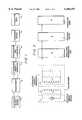
- FIG. 1shows a block diagram of a first embodiment of an apparatus according to the present invention
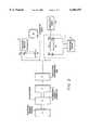
- FIG. 2shows a schematic diagram of a second embodiment of an apparatus according to the present invention, employing a sequential resonance circuit
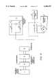
- FIG. 3shows a power supply diagram for receiving devices operating on alternating current
- FIG. 4shows a power supply diagram for receiving devices operating on direct current.
- the first embodiment of the inventionprovides apparatus adapted for use in a method of supplying power to electrical devices, including the generation and transformation of electrical energy with its subsequent transmission to a receiving device via a transmission line, the method being distinguished by the fact that the electrical energy generated is transformed into the energy of oscillation of a field of free electrical charges (the displacement current or longitudinal wave of an electrical field), the density of which charges varies in time, and this energy is transmitted via a conductor of the transmission line which does not form a closed circuit and, where necessary, transformed into the electromagnetic energy of conductive currents.
- FIG. 1there is illustrated an apparatus for initial source of electrical energy 1, a transformer (of current, voltage or frequency) 2, an alternating density generator of free electrical charges 3, which charges flow under the influence of coulomb forces along a transmission line or conductor 4, through a consuming device 5, to any conductive body 6, which has an equivalent (natural) capacity sufficient to provide for the normal working of the consuming device 5.
- a transformerof current, voltage or frequency
- an alternating density generator of free electrical charges 3which charges flow under the influence of coulomb forces along a transmission line or conductor 4
- any conductive body 6which has an equivalent (natural) capacity sufficient to provide for the normal working of the consuming device 5.
- the apparatusmay be constructed on the basis of a generator of displacement current (longitudinal wave of an electrical field), using a sequential resonance circuit (FIG. 2) in the form of two interconnected inductors L1 and L2 such that an equivalent inductivity Leg of the resonance circuit is provided, in the simplest case of idle running, by the resultant inductivity L1 and L2, and the equivalent capacity is provided by the resultant (natural) capacity of the resonance circuit.
- a sequential resonance circuitFIG. 2
- FIG. 2sequential resonance circuit in the form of two interconnected inductors L1 and L2 such that an equivalent inductivity Leg of the resonance circuit is provided, in the simplest case of idle running, by the resultant inductivity L1 and L2, and the equivalent capacity is provided by the resultant (natural) capacity of the resonance circuit.
- the other input terminal Bx3 of the receiving deviceis either earthed or connected to any conductive body 6 possessing an equivalent (natural) capacity adequate to ensure the normal working of the receiving device 5; or
- FIG. 3a transformer circuit consisting of two interconnected inductors L3 and L4, such that the two ends Bx3 and Bx4 of the inductor L3 are connected to the receiving device 5, while one end of the ends Bx5 of the second inductor L4 is connected to the output of the conductor of the transmission line which does not form a closed circuit 4, and the other end Bx6 of the inductor L4 is connected to any conductive body 6, with an equivalent (natural) capacity selected in order to provide the nominal power consumption of the receiving device 5.
- a transformer circuitFIG. 3
- the output of the conductor of the transmission line which does not form a closed circuit 4is connected to an accommodation circuit in the form of either:
- a diode circuitsuch that output or the conductor 4 is connected to the common point of the anode of the first diode VD1 and the cathode of the second diode VD2, while the cathode of the first diode VD1 and the anode of the second diode VD2 are the outlets 01 and 02 to be connected to the receiving device 5, either directly or with a capacitor connected in parallel;
- FIG. 4a transformer circuit (FIG. 4) employing two interconnected inductors L5, L6, such that the receiving device 5 is connected to the inductor L5 via the rectifying circuit.
- the method for supply of power to electrical devices and the apparatus for the implementation of this method, according to the inventionpossess a high degree of reliability due to the absence of complex electronic or mechanical assemblies. They permit the use of inexpensive mass-produced radio-electronic components and their working cycle is automatically regulated to a high degree.
- the inventionis intended for the creation of a highly efficient means for the transformation and transmission of electrical energy, and also for the creation of both permanent and mobile devices for the transmission of electrical energy from an initial source to a consuming device via a transmission line which does not form a closed circuit, ie a single-wire transmission line.
- the inventionmay be used conjointly with various power-engineering and technological processes which involve the use of super-high voltage electrical and electromagnetic fields, electron beams and super-long wave radio communications, when it will make possible a sharp reduction in the dimensions and weight of equipment as compared with the means traditionally employed.
- the proposed apparatuswhich may be termed a "monovibrator” may consist of two inductively connected much layered coils in accordance with the scheme of a consecutive resonance circuit.
- the secondary coilconsists of up to some tens of thousands of turns of thin isolated wire with the turns wound one to another in many layers on a dialectic core. Disposition of the primary coil in respect to the secondary one doesn't matter much. What does matter is an inductive link which determines potential transmitted from the primary to the secondary coil.
- the monovibratormay or may not have a ferromagnetic core. The ferromagnetic core influences the width of the working frequency bandwidth--it broadens it.
- High working outcoming voltageis the result of a high coefficient of transformation, as the primary coil usually contains a couple of dozens of winds for working frequencies ranging from 1 kHz to a couple of hundred kHz.
- a preferred working frequencyis 5 kHz.
- the load of the monovibrator when running idleacquires capacitance character that means which it is reactive.
- the magnitude of an active constituent of a monoconductive line with the consecutive resonanceis rather low and its incoming resistance is approaching zero. That is why with rather a powerful primary source the consecutive resonance makes it possible to transmit more power through the monoconductive line in case there is an outtake of this power at the other line terminal, which is opposite to the primary source of power.
- Reaction of the monoconductive line of any lengthcan always be compensated by regulating the frequency of the primary source (generator, converting devices), thus providing consecutive resonance in the line itself with all the magnitudes of incoming and outgoing characteristics arising therefrom.
- the method and apparatus of the present inventiondoes not have the drawbacks of previously known single line systems.
Landscapes
- Engineering & Computer Science (AREA)
- Power Engineering (AREA)
- Computer Networks & Wireless Communication (AREA)
- Signal Processing (AREA)
- Near-Field Transmission Systems (AREA)
- Rectifiers (AREA)
- Cable Transmission Systems, Equalization Of Radio And Reduction Of Echo (AREA)
- Ac-Ac Conversion (AREA)
Abstract
Description
Claims (23)
Applications Claiming Priority (3)
| Application Number | Priority Date | Filing Date | Title |
|---|---|---|---|
| SU5036137 | 1992-05-08 | ||
| RU5036137 | 1992-05-08 | ||
| PCT/GB1993/000960WO1993023907A1 (en) | 1992-05-08 | 1993-05-10 | Apparatus and method for single line electrical transmission |
Publications (1)
| Publication Number | Publication Date |
|---|---|
| US6104107Atrue US6104107A (en) | 2000-08-15 |
Family
ID=21601257
Family Applications (1)
| Application Number | Title | Priority Date | Filing Date |
|---|---|---|---|
| US08/331,658Expired - LifetimeUS6104107A (en) | 1992-05-08 | 1993-05-10 | Method and apparatus for single line electrical transmission |
Country Status (8)
| Country | Link |
|---|---|
| US (1) | US6104107A (en) |
| EP (1) | EP0639301B1 (en) |
| JP (1) | JPH07506716A (en) |
| KR (1) | KR100345984B1 (en) |
| AU (1) | AU4078393A (en) |
| CA (1) | CA2135299C (en) |
| DE (1) | DE69313631T2 (en) |
| WO (1) | WO1993023907A1 (en) |
Cited By (88)
| Publication number | Priority date | Publication date | Assignee | Title |
|---|---|---|---|---|
| US20030200651A1 (en)* | 2001-11-29 | 2003-10-30 | Gibson Gary A. | Microfabricated Van De Graaf |
| US20040014492A1 (en)* | 2002-03-15 | 2004-01-22 | Michael Miskin | Method and apparatus for wireless public internet access |
| US20040124996A1 (en)* | 2001-07-27 | 2004-07-01 | James Andersen | Data transmission apparatus and method |
| WO2003075126A3 (en)* | 2002-02-28 | 2004-12-02 | Lynk Labs Inc | One wire self referencing circuits for providing power and data |
| FR2875649A1 (en)* | 2004-09-21 | 2006-03-24 | Henri Bondar | Electric power transmission device for e.g. electric household appliance, has electric dipoles aligned on same axis, and generating and electromotive electrodes that are active and covered by solid insulating material |
| WO2010151161A2 (en) | 2009-06-22 | 2010-12-29 | De Alves Martins Baptista | Propulsion system using the antigravity force of the vacuum and applications |
| US20110175457A1 (en)* | 2010-01-21 | 2011-07-21 | Sony Corporation | Power supplying apparatus, power receiving apparatus, and wireless power supplying system |
| WO2013018084A1 (en)* | 2011-08-04 | 2013-02-07 | Michael Bank | A single-wire electric system |
| WO2014160096A1 (en) | 2013-03-13 | 2014-10-02 | Federal Law Enforcement Development Services, Inc. | Led light control and management system |
| CN104467203A (en)* | 2014-12-10 | 2015-03-25 | 杨培应 | Bidirectional magnetic induction corresponding machine |
| US20150229232A1 (en)* | 2011-08-04 | 2015-08-13 | Michael Bank | Electrical energy transmission system |
| US9306527B1 (en) | 2015-05-29 | 2016-04-05 | Gradient Dynamics Llc | Systems, apparatuses, and methods for generating and/or utilizing scalar-longitudinal waves |
| US9496921B1 (en) | 2015-09-09 | 2016-11-15 | Cpg Technologies | Hybrid guided surface wave communication |
| RU172332U1 (en)* | 2017-01-09 | 2017-07-04 | Федеральное государственное бюджетное учреждение "Петербургский институт ядерной физики" им. Б.П. Константинова | AC GENERATOR IN Inductance Coil |
| US9859707B2 (en) | 2014-09-11 | 2018-01-02 | Cpg Technologies, Llc | Simultaneous multifrequency receive circuits |
| US9857402B2 (en) | 2015-09-08 | 2018-01-02 | CPG Technologies, L.L.C. | Measuring and reporting power received from guided surface waves |
| US9882397B2 (en) | 2014-09-11 | 2018-01-30 | Cpg Technologies, Llc | Guided surface wave transmission of multiple frequencies in a lossy media |
| US9882436B2 (en) | 2015-09-09 | 2018-01-30 | Cpg Technologies, Llc | Return coupled wireless power transmission |
| US9887556B2 (en) | 2014-09-11 | 2018-02-06 | Cpg Technologies, Llc | Chemically enhanced isolated capacitance |
| US9885742B2 (en) | 2015-09-09 | 2018-02-06 | Cpg Technologies, Llc | Detecting unauthorized consumption of electrical energy |
| US9887585B2 (en) | 2015-09-08 | 2018-02-06 | Cpg Technologies, Llc | Changing guided surface wave transmissions to follow load conditions |
| US9887557B2 (en) | 2014-09-11 | 2018-02-06 | Cpg Technologies, Llc | Hierarchical power distribution |
| US9887558B2 (en) | 2015-09-09 | 2018-02-06 | Cpg Technologies, Llc | Wired and wireless power distribution coexistence |
| US9887587B2 (en) | 2014-09-11 | 2018-02-06 | Cpg Technologies, Llc | Variable frequency receivers for guided surface wave transmissions |
| US9893403B2 (en) | 2015-09-11 | 2018-02-13 | Cpg Technologies, Llc | Enhanced guided surface waveguide probe |
| US9893402B2 (en) | 2014-09-11 | 2018-02-13 | Cpg Technologies, Llc | Superposition of guided surface waves on lossy media |
| US9899718B2 (en) | 2015-09-11 | 2018-02-20 | Cpg Technologies, Llc | Global electrical power multiplication |
| US9910144B2 (en) | 2013-03-07 | 2018-03-06 | Cpg Technologies, Llc | Excitation and use of guided surface wave modes on lossy media |
| US9912031B2 (en) | 2013-03-07 | 2018-03-06 | Cpg Technologies, Llc | Excitation and use of guided surface wave modes on lossy media |
| US9916485B1 (en) | 2015-09-09 | 2018-03-13 | Cpg Technologies, Llc | Method of managing objects using an electromagnetic guided surface waves over a terrestrial medium |
| US9923385B2 (en) | 2015-06-02 | 2018-03-20 | Cpg Technologies, Llc | Excitation and use of guided surface waves |
| US9921256B2 (en) | 2015-09-08 | 2018-03-20 | Cpg Technologies, Llc | Field strength monitoring for optimal performance |
| US9927477B1 (en) | 2015-09-09 | 2018-03-27 | Cpg Technologies, Llc | Object identification system and method |
| US9941566B2 (en) | 2014-09-10 | 2018-04-10 | Cpg Technologies, Llc | Excitation and use of guided surface wave modes on lossy media |
| US9960470B2 (en) | 2014-09-11 | 2018-05-01 | Cpg Technologies, Llc | Site preparation for guided surface wave transmission in a lossy media |
| US9973037B1 (en) | 2015-09-09 | 2018-05-15 | Cpg Technologies, Llc | Object identification system and method |
| US9997040B2 (en) | 2015-09-08 | 2018-06-12 | Cpg Technologies, Llc | Global emergency and disaster transmission |
| US10001553B2 (en) | 2014-09-11 | 2018-06-19 | Cpg Technologies, Llc | Geolocation with guided surface waves |
| US10027131B2 (en) | 2015-09-09 | 2018-07-17 | CPG Technologies, Inc. | Classification of transmission |
| US10027177B2 (en) | 2015-09-09 | 2018-07-17 | Cpg Technologies, Llc | Load shedding in a guided surface wave power delivery system |
| US10027116B2 (en) | 2014-09-11 | 2018-07-17 | Cpg Technologies, Llc | Adaptation of polyphase waveguide probes |
| US10033197B2 (en) | 2015-09-09 | 2018-07-24 | Cpg Technologies, Llc | Object identification system and method |
| US10031208B2 (en) | 2015-09-09 | 2018-07-24 | Cpg Technologies, Llc | Object identification system and method |
| US10033198B2 (en) | 2014-09-11 | 2018-07-24 | Cpg Technologies, Llc | Frequency division multiplexing for wireless power providers |
| US10062944B2 (en) | 2015-09-09 | 2018-08-28 | CPG Technologies, Inc. | Guided surface waveguide probes |
| US10063095B2 (en) | 2015-09-09 | 2018-08-28 | CPG Technologies, Inc. | Deterring theft in wireless power systems |
| US10074993B2 (en) | 2014-09-11 | 2018-09-11 | Cpg Technologies, Llc | Simultaneous transmission and reception of guided surface waves |
| US10079573B2 (en) | 2014-09-11 | 2018-09-18 | Cpg Technologies, Llc | Embedding data on a power signal |
| US10084223B2 (en) | 2014-09-11 | 2018-09-25 | Cpg Technologies, Llc | Modulated guided surface waves |
| US10103452B2 (en) | 2015-09-10 | 2018-10-16 | Cpg Technologies, Llc | Hybrid phased array transmission |
| US10101444B2 (en) | 2014-09-11 | 2018-10-16 | Cpg Technologies, Llc | Remote surface sensing using guided surface wave modes on lossy media |
| US10122218B2 (en) | 2015-09-08 | 2018-11-06 | Cpg Technologies, Llc | Long distance transmission of offshore power |
| US10135301B2 (en) | 2015-09-09 | 2018-11-20 | Cpg Technologies, Llc | Guided surface waveguide probes |
| US10141622B2 (en) | 2015-09-10 | 2018-11-27 | Cpg Technologies, Llc | Mobile guided surface waveguide probes and receivers |
| US10175203B2 (en) | 2014-09-11 | 2019-01-08 | Cpg Technologies, Llc | Subsurface sensing using guided surface wave modes on lossy media |
| US10175048B2 (en) | 2015-09-10 | 2019-01-08 | Cpg Technologies, Llc | Geolocation using guided surface waves |
| US10193595B2 (en) | 2015-06-02 | 2019-01-29 | Cpg Technologies, Llc | Excitation and use of guided surface waves |
| US10193229B2 (en) | 2015-09-10 | 2019-01-29 | Cpg Technologies, Llc | Magnetic coils having cores with high magnetic permeability |
| US10205326B2 (en) | 2015-09-09 | 2019-02-12 | Cpg Technologies, Llc | Adaptation of energy consumption node for guided surface wave reception |
| US10230270B2 (en) | 2015-09-09 | 2019-03-12 | Cpg Technologies, Llc | Power internal medical devices with guided surface waves |
| US10312747B2 (en) | 2015-09-10 | 2019-06-04 | Cpg Technologies, Llc | Authentication to enable/disable guided surface wave receive equipment |
| US10324163B2 (en) | 2015-09-10 | 2019-06-18 | Cpg Technologies, Llc | Geolocation using guided surface waves |
| US10396566B2 (en) | 2015-09-10 | 2019-08-27 | Cpg Technologies, Llc | Geolocation using guided surface waves |
| US10408915B2 (en) | 2015-09-10 | 2019-09-10 | Cpg Technologies, Llc | Geolocation using guided surface waves |
| US10408916B2 (en) | 2015-09-10 | 2019-09-10 | Cpg Technologies, Llc | Geolocation using guided surface waves |
| US10447342B1 (en) | 2017-03-07 | 2019-10-15 | Cpg Technologies, Llc | Arrangements for coupling the primary coil to the secondary coil |
| US10498006B2 (en) | 2015-09-10 | 2019-12-03 | Cpg Technologies, Llc | Guided surface wave transmissions that illuminate defined regions |
| US10498393B2 (en) | 2014-09-11 | 2019-12-03 | Cpg Technologies, Llc | Guided surface wave powered sensing devices |
| US10559893B1 (en) | 2015-09-10 | 2020-02-11 | Cpg Technologies, Llc | Pulse protection circuits to deter theft |
| US10559867B2 (en) | 2017-03-07 | 2020-02-11 | Cpg Technologies, Llc | Minimizing atmospheric discharge within a guided surface waveguide probe |
| US10560147B1 (en) | 2017-03-07 | 2020-02-11 | Cpg Technologies, Llc | Guided surface waveguide probe control system |
| US10559866B2 (en) | 2017-03-07 | 2020-02-11 | Cpg Technologies, Inc | Measuring operational parameters at the guided surface waveguide probe |
| US10581492B1 (en) | 2017-03-07 | 2020-03-03 | Cpg Technologies, Llc | Heat management around a phase delay coil in a probe |
| US10608311B2 (en) | 2017-02-23 | 2020-03-31 | Intel Corporation | Cable assembly comprising a single wire coupled to a signal launcher and housed in a first cover portion and in a second ferrite cover portion |
| US10630111B2 (en) | 2017-03-07 | 2020-04-21 | Cpg Technologies, Llc | Adjustment of guided surface waveguide probe operation |
| US10847859B2 (en) | 2017-02-23 | 2020-11-24 | Intel Corporation | Single wire communication arrangement |
| US10998993B2 (en) | 2015-09-10 | 2021-05-04 | CPG Technologies, Inc. | Global time synchronization using a guided surface wave |
| WO2021137065A1 (en) | 2019-12-30 | 2021-07-08 | Folquer Holdings Limited | An electric power system and a method of transmitting electric power from a power source to a device via a single-wire |
| US11201672B2 (en) | 2007-05-24 | 2021-12-14 | Federal Law Enforcement Development Services, Inc. | LED light fixture |
| US11200794B2 (en) | 2015-08-11 | 2021-12-14 | Federal Law Enforcement Development Services, Inc. | Function disabler device and system |
| US11265082B2 (en) | 2007-05-24 | 2022-03-01 | Federal Law Enforcement Development Services, Inc. | LED light control assembly and system |
| US11393387B2 (en) | 2018-07-05 | 2022-07-19 | AhuraTech LLC | Open-circuit electroluminescence |
| US11424781B2 (en) | 2009-04-01 | 2022-08-23 | Federal Law Enforcement Development Services, Inc. | Visible light communication transceiver glasses |
| US11428656B2 (en) | 2018-07-05 | 2022-08-30 | AhuraTech LLC | Electroluminescent methods and system for real-time measurements of physical properties |
| US11460403B2 (en) | 2018-07-05 | 2022-10-04 | AhuraTech LLC | Electroluminescent methods and devices for characterization of biological specimens |
| US11552712B2 (en) | 2013-05-06 | 2023-01-10 | Federal Law Enforcement Development Services, Inc. | Network security and variable pulse wave form with continuous communication |
| US11783345B2 (en) | 2014-01-15 | 2023-10-10 | Federal Law Enforcement Development Services, Inc. | Cyber life electronic networking and commerce operating exchange |
| WO2024076254A1 (en)* | 2022-10-03 | 2024-04-11 | Общество с ограниченной ответственностью "Три-Лоджик" | Method and system for transmitting information over a single-wire transmission line |
Families Citing this family (8)
| Publication number | Priority date | Publication date | Assignee | Title |
|---|---|---|---|---|
| US5493691A (en)* | 1993-12-23 | 1996-02-20 | Barrett; Terence W. | Oscillator-shuttle-circuit (OSC) networks for conditioning energy in higher-order symmetry algebraic topological forms and RF phase conjugation |
| US6459218B2 (en) | 1994-07-13 | 2002-10-01 | Auckland Uniservices Limited | Inductively powered lamp unit |
| DE69535873D1 (en)* | 1994-07-13 | 2008-12-04 | Auckland Uniservices Ltd | Inductively fed lighting |
| RU2255405C2 (en)* | 2003-02-07 | 2005-06-27 | Государственное научное учреждение Всероссийский научно-исследовательский институт электрификации сельского хозяйства (ГНУ ВИЭСХ) | Method and device for electrical energy transmission |
| JP4962560B2 (en) | 2006-03-21 | 2012-06-27 | 株式会社村田製作所 | Energy carrier with partial influence through a dielectric medium |
| CN106160250B (en)* | 2015-04-14 | 2021-01-29 | 刘泽宇 | Wireless power transmission system |
| CN106160252B (en)* | 2015-04-14 | 2021-01-29 | 刘泽宇 | Transmitting terminal of wireless power transmission system |
| CN106160251B (en)* | 2015-04-14 | 2021-01-29 | 刘泽宇 | Receiving terminal of wireless power transmission system |
Citations (3)
| Publication number | Priority date | Publication date | Assignee | Title |
|---|---|---|---|---|
| US454622A (en)* | 1891-06-23 | Nikola Tesla | System Of Electric Llghting | |
| US568176A (en)* | 1896-09-22 | Nikola tesla | ||
| US593138A (en)* | 1897-11-02 | Nikola Tesla | Electrical Transformer |
- 1993
- 1993-05-10USUS08/331,658patent/US6104107A/ennot_activeExpired - Lifetime
- 1993-05-10CACA002135299Apatent/CA2135299C/ennot_activeExpired - Fee Related
- 1993-05-10AUAU40783/93Apatent/AU4078393A/ennot_activeAbandoned
- 1993-05-10EPEP93910175Apatent/EP0639301B1/ennot_activeExpired - Lifetime
- 1993-05-10DEDE69313631Tpatent/DE69313631T2/ennot_activeExpired - Fee Related
- 1993-05-10JPJP5519980Apatent/JPH07506716A/enactivePending
- 1993-05-10WOPCT/GB1993/000960patent/WO1993023907A1/enactiveIP Right Grant
- 1994
- 1994-11-08KRKR1019940704023Apatent/KR100345984B1/ennot_activeExpired - Lifetime
Patent Citations (3)
| Publication number | Priority date | Publication date | Assignee | Title |
|---|---|---|---|---|
| US454622A (en)* | 1891-06-23 | Nikola Tesla | System Of Electric Llghting | |
| US568176A (en)* | 1896-09-22 | Nikola tesla | ||
| US593138A (en)* | 1897-11-02 | Nikola Tesla | Electrical Transformer |
Non-Patent Citations (40)
| Title |
|---|
| "Fachlexikon ABC Physik," VEB Edition Leipzig (1974) p. 1548. |
| "The Large Soviet Encyclopedia," vol. 26 (Moscow Publishing House 1977). |
| B.N. Rzhonsnitsky, "Nikola Tesla" (Molodaya Gvardiya 1959) pp. 6-7, 116-120. |
| B.N. Rzhonsnitsky, Nikola Tesla (Molodaya Gvardiya 1959) pp. 6 7, 116 120.* |
| C. Gillispie, "Dictionary of Scientific Biography," vol. IV, pp. 532-535 (Charles Scribner's Sons 1971). |
| C. Gillispie, "Dictionary of Scientific Biography," vol. IX, pp. 209-213 (Charles Scribner's Sons 1974). |
| C. Gillispie, "Dictionary of Scientific Biography," vol. V, pp. 515-517 (Charles Scribner's Sons 1972). |
| C. Gillispie, Dictionary of Scientific Biography, vol. IV, pp. 532 535 (Charles Scribner s Sons 1971).* |
| C. Gillispie, Dictionary of Scientific Biography, vol. IX, pp. 209 213 (Charles Scribner s Sons 1974).* |
| C. Gillispie, Dictionary of Scientific Biography, vol. V, pp. 515 517 (Charles Scribner s Sons 1972).* |
| Fachlexikon ABC Physik, VEB Edition Leipzig (1974) p. 1548.* |
| G. Polvani, "Allessandro Volta" (Domus Galil.ae butted.ana 1942), pp. 340-353, 485. |
| G. Polvani, Allessandro Volta (Domus Galil ana 1942), pp. 340 353, 485.* |
| G. Trinkaus, "Tesla--The Lost Inventions," Vantage Press (1988) pp. 13-14. |
| G. Trinkaus, Tesla The Lost Inventions, Vantage Press (1988) pp. 13 14.* |
| G.K. Tsverava, "Nikola Tesla" (Nauka 1974) pp. 160-161, 176-177. |
| G.K. Tsverava, Nikola Tesla (Nauka 1974) pp. 160 161, 176 177.* |
| Grotz, "Wireless Transmission of Power, An Attempt To Verify Nikola Tesla's 1899 Colorado Springs Expriments, Results Of Research And Experimentation," Proceedings of the 26th IECEC Conference, vol. 4 (1991) pp. 404-409. |
| Grotz, Wireless Transmission of Power, An Attempt To Verify Nikola Tesla s 1899 Colorado Springs Expriments, Results Of Research And Experimentation, Proceedings of the 26th IECEC Conference, vol. 4 (1991) pp. 404 409.* |
| I. V. Alyamovsky, Electron Beams and Electron Guns (Moscow 1966), pp. 13 13 15, 59, and 108.* |
| I. V. Alyamovsky, Electron Beams and Electron Guns (Moscow 1966), pp. 13-13-15, 59, and 108. |
| J.J. O Neill, Prodical Genius, The life of Nikola Tesla (Neville Spearman 1968) pp. 70 73, 128 133.* |
| J.J. O'Neill, "Prodical Genius, The life of Nikola Tesla" (Neville Spearman 1968) pp. 70-73, 128-133. |
| J.K. Maxwell, "Selected Works on Electromagnetic Field Theory" (Gosizdat 1952) pp. 252-255, 320-321. |
| J.K. Maxwell, Selected Works on Electromagnetic Field Theory (Gosizdat 1952) pp. 252 255, 320 321.* |
| John O Neill, Electrical Prometheus (History of Technology ( Molodaya Gvardiya ) 1959).* |
| John O'Neill, "Electrical Prometheus" (History of Technology ("Molodaya Gvardiya") 1959). |
| K.E. Swartz, "The Uncommon Physics of Common Phenomena," vol. 2 (1987), p. 148. |
| K.E. Swartz, The Uncommon Physics of Common Phenomena, vol. 2 (1987), p. 148.* |
| M. Faraday, "Experimental Researches in Electricity" (Dover Publications, Inc. 1839), pp. 24-29. |
| M. Faraday, Experimental Researches in Electricity (Dover Publications, Inc. 1839), pp. 24 29.* |
| M.I. Radovski, "Galvani and Volta," (1941), pp. 30-31, 58-59. |
| M.I. Radovski, Galvani and Volta, (1941), pp. 30 31, 58 59.* |
| N. Tesla, "The True Wireless," Electrical Experimenter (May 1919). |
| N. Tesla, The True Wireless, Electrical Experimenter (May 1919).* |
| The Large Soviet Encyclopedia, vol. 26 (Moscow Publishing House 1977).* |
| V.N. Dulin and M.S. Zhuk (editors), Manual of Radio and Electronic Equipment Components (Moscow 1977), pp. 69 70.* |
| V.N. Dulin and M.S. Zhuk (editors), Manual of Radio and Electronic Equipment Components (Moscow 1977), pp. 69-70. |
| Y. A. Khramov, "Physicists: A Biographical Reference Book" (Nauka 1983), pp. 8-9, 20-23, 26-27, 80-81, 84-85, 86-95, 102-103, 106-131, 136-139, 142-143, 178-179, 240-241. |
| Y. A. Khramov, Physicists: A Biographical Reference Book (Nauka 1983), pp. 8 9, 20 23, 26 27, 80 81, 84 85, 86 95, 102 103, 106 131, 136 139, 142 143, 178 179, 240 241.* |
Cited By (127)
| Publication number | Priority date | Publication date | Assignee | Title |
|---|---|---|---|---|
| US20040124996A1 (en)* | 2001-07-27 | 2004-07-01 | James Andersen | Data transmission apparatus and method |
| US6978537B2 (en)* | 2001-11-29 | 2005-12-27 | Hewlett-Packard Development Company, L.P. | Method of transferring electric charge using a micrometer-scaled device |
| US20030200651A1 (en)* | 2001-11-29 | 2003-10-30 | Gibson Gary A. | Microfabricated Van De Graaf |
| CN1639940B (en)* | 2002-02-28 | 2012-07-18 | 莱恩克实验股份有限公司 | One wire self referencing circuits for providing power and data |
| WO2003075126A3 (en)* | 2002-02-28 | 2004-12-02 | Lynk Labs Inc | One wire self referencing circuits for providing power and data |
| US20050173990A1 (en)* | 2002-02-28 | 2005-08-11 | Andersen James N. | One wire self referencing circuits for providing power and data |
| US8742630B2 (en) | 2002-02-28 | 2014-06-03 | Lynk Labs, Inc. | One wire self referencing circuits for providing power and data |
| US20040014492A1 (en)* | 2002-03-15 | 2004-01-22 | Michael Miskin | Method and apparatus for wireless public internet access |
| FR2875649A1 (en)* | 2004-09-21 | 2006-03-24 | Henri Bondar | Electric power transmission device for e.g. electric household appliance, has electric dipoles aligned on same axis, and generating and electromotive electrodes that are active and covered by solid insulating material |
| US11201672B2 (en) | 2007-05-24 | 2021-12-14 | Federal Law Enforcement Development Services, Inc. | LED light fixture |
| US11265082B2 (en) | 2007-05-24 | 2022-03-01 | Federal Law Enforcement Development Services, Inc. | LED light control assembly and system |
| US11664897B2 (en) | 2007-05-24 | 2023-05-30 | Federal Law Enforcement Development Services, Inc. | LED light fixture |
| US11664895B2 (en) | 2007-05-24 | 2023-05-30 | Federal Law Enforcement Development Services, Inc. | LED light control assembly and system |
| US11424781B2 (en) | 2009-04-01 | 2022-08-23 | Federal Law Enforcement Development Services, Inc. | Visible light communication transceiver glasses |
| WO2010151161A2 (en) | 2009-06-22 | 2010-12-29 | De Alves Martins Baptista | Propulsion system using the antigravity force of the vacuum and applications |
| US20110175457A1 (en)* | 2010-01-21 | 2011-07-21 | Sony Corporation | Power supplying apparatus, power receiving apparatus, and wireless power supplying system |
| CN102136764B (en)* | 2010-01-21 | 2015-04-15 | 索尼公司 | Power supplying apparatus, power receiving apparatus and wireless power supplying system |
| CN102136764A (en)* | 2010-01-21 | 2011-07-27 | 索尼公司 | Power supplying apparatus, power receiving apparatus and wireless power supplying system |
| US9246405B2 (en)* | 2011-08-04 | 2016-01-26 | Sle International, Llc | Electrical energy transmission system with a single transmission line |
| WO2013018084A1 (en)* | 2011-08-04 | 2013-02-07 | Michael Bank | A single-wire electric system |
| US20150229232A1 (en)* | 2011-08-04 | 2015-08-13 | Michael Bank | Electrical energy transmission system |
| US9608441B2 (en) | 2011-08-04 | 2017-03-28 | Sle International Llc. | Single-wire electric transmission line |
| US9910144B2 (en) | 2013-03-07 | 2018-03-06 | Cpg Technologies, Llc | Excitation and use of guided surface wave modes on lossy media |
| US10680306B2 (en) | 2013-03-07 | 2020-06-09 | CPG Technologies, Inc. | Excitation and use of guided surface wave modes on lossy media |
| US9912031B2 (en) | 2013-03-07 | 2018-03-06 | Cpg Technologies, Llc | Excitation and use of guided surface wave modes on lossy media |
| WO2014160096A1 (en) | 2013-03-13 | 2014-10-02 | Federal Law Enforcement Development Services, Inc. | Led light control and management system |
| US11824586B2 (en) | 2013-05-06 | 2023-11-21 | Federal Law Enforcement Development Services, Inc. | Network security and variable pulse wave form with continuous communication |
| US11552712B2 (en) | 2013-05-06 | 2023-01-10 | Federal Law Enforcement Development Services, Inc. | Network security and variable pulse wave form with continuous communication |
| US11783345B2 (en) | 2014-01-15 | 2023-10-10 | Federal Law Enforcement Development Services, Inc. | Cyber life electronic networking and commerce operating exchange |
| US10998604B2 (en) | 2014-09-10 | 2021-05-04 | Cpg Technologies, Llc | Excitation and use of guided surface wave modes on lossy media |
| US9941566B2 (en) | 2014-09-10 | 2018-04-10 | Cpg Technologies, Llc | Excitation and use of guided surface wave modes on lossy media |
| US10224589B2 (en) | 2014-09-10 | 2019-03-05 | Cpg Technologies, Llc | Excitation and use of guided surface wave modes on lossy media |
| US9887557B2 (en) | 2014-09-11 | 2018-02-06 | Cpg Technologies, Llc | Hierarchical power distribution |
| US10381843B2 (en) | 2014-09-11 | 2019-08-13 | Cpg Technologies, Llc | Hierarchical power distribution |
| US10177571B2 (en) | 2014-09-11 | 2019-01-08 | Cpg Technologies, Llc | Simultaneous multifrequency receive circuits |
| US9893402B2 (en) | 2014-09-11 | 2018-02-13 | Cpg Technologies, Llc | Superposition of guided surface waves on lossy media |
| US10135298B2 (en) | 2014-09-11 | 2018-11-20 | Cpg Technologies, Llc | Variable frequency receivers for guided surface wave transmissions |
| US9887556B2 (en) | 2014-09-11 | 2018-02-06 | Cpg Technologies, Llc | Chemically enhanced isolated capacitance |
| US10153638B2 (en) | 2014-09-11 | 2018-12-11 | Cpg Technologies, Llc | Adaptation of polyphase waveguide probes |
| US9882397B2 (en) | 2014-09-11 | 2018-01-30 | Cpg Technologies, Llc | Guided surface wave transmission of multiple frequencies in a lossy media |
| US9887587B2 (en) | 2014-09-11 | 2018-02-06 | Cpg Technologies, Llc | Variable frequency receivers for guided surface wave transmissions |
| US9859707B2 (en) | 2014-09-11 | 2018-01-02 | Cpg Technologies, Llc | Simultaneous multifrequency receive circuits |
| US10498393B2 (en) | 2014-09-11 | 2019-12-03 | Cpg Technologies, Llc | Guided surface wave powered sensing devices |
| US10084223B2 (en) | 2014-09-11 | 2018-09-25 | Cpg Technologies, Llc | Modulated guided surface waves |
| US9960470B2 (en) | 2014-09-11 | 2018-05-01 | Cpg Technologies, Llc | Site preparation for guided surface wave transmission in a lossy media |
| US10101444B2 (en) | 2014-09-11 | 2018-10-16 | Cpg Technologies, Llc | Remote surface sensing using guided surface wave modes on lossy media |
| US10355481B2 (en) | 2014-09-11 | 2019-07-16 | Cpg Technologies, Llc | Simultaneous multifrequency receive circuits |
| US10001553B2 (en) | 2014-09-11 | 2018-06-19 | Cpg Technologies, Llc | Geolocation with guided surface waves |
| US10355480B2 (en) | 2014-09-11 | 2019-07-16 | Cpg Technologies, Llc | Adaptation of polyphase waveguide probes |
| US10320045B2 (en) | 2014-09-11 | 2019-06-11 | Cpg Technologies, Llc | Superposition of guided surface waves on lossy media |
| US10027116B2 (en) | 2014-09-11 | 2018-07-17 | Cpg Technologies, Llc | Adaptation of polyphase waveguide probes |
| US10320200B2 (en) | 2014-09-11 | 2019-06-11 | Cpg Technologies, Llc | Chemically enhanced isolated capacitance |
| US10079573B2 (en) | 2014-09-11 | 2018-09-18 | Cpg Technologies, Llc | Embedding data on a power signal |
| US10033198B2 (en) | 2014-09-11 | 2018-07-24 | Cpg Technologies, Llc | Frequency division multiplexing for wireless power providers |
| US10175203B2 (en) | 2014-09-11 | 2019-01-08 | Cpg Technologies, Llc | Subsurface sensing using guided surface wave modes on lossy media |
| US10193353B2 (en) | 2014-09-11 | 2019-01-29 | Cpg Technologies, Llc | Guided surface wave transmission of multiple frequencies in a lossy media |
| US10074993B2 (en) | 2014-09-11 | 2018-09-11 | Cpg Technologies, Llc | Simultaneous transmission and reception of guided surface waves |
| CN104467203B (en)* | 2014-12-10 | 2016-08-17 | 杨培应 | Two-way magnetic strength correspondence machine |
| CN104467203A (en)* | 2014-12-10 | 2015-03-25 | 杨培应 | Bidirectional magnetic induction corresponding machine |
| US9306527B1 (en) | 2015-05-29 | 2016-04-05 | Gradient Dynamics Llc | Systems, apparatuses, and methods for generating and/or utilizing scalar-longitudinal waves |
| US9923385B2 (en) | 2015-06-02 | 2018-03-20 | Cpg Technologies, Llc | Excitation and use of guided surface waves |
| US10193595B2 (en) | 2015-06-02 | 2019-01-29 | Cpg Technologies, Llc | Excitation and use of guided surface waves |
| US11651680B2 (en) | 2015-08-11 | 2023-05-16 | Federal Law Enforcement Development Services, Inc. | Function disabler device and system |
| US11200794B2 (en) | 2015-08-11 | 2021-12-14 | Federal Law Enforcement Development Services, Inc. | Function disabler device and system |
| US10132845B2 (en) | 2015-09-08 | 2018-11-20 | Cpg Technologies, Llc | Measuring and reporting power received from guided surface waves |
| US10274527B2 (en) | 2015-09-08 | 2019-04-30 | CPG Technologies, Inc. | Field strength monitoring for optimal performance |
| US9857402B2 (en) | 2015-09-08 | 2018-01-02 | CPG Technologies, L.L.C. | Measuring and reporting power received from guided surface waves |
| US9887585B2 (en) | 2015-09-08 | 2018-02-06 | Cpg Technologies, Llc | Changing guided surface wave transmissions to follow load conditions |
| US10122218B2 (en) | 2015-09-08 | 2018-11-06 | Cpg Technologies, Llc | Long distance transmission of offshore power |
| US9921256B2 (en) | 2015-09-08 | 2018-03-20 | Cpg Technologies, Llc | Field strength monitoring for optimal performance |
| US10467876B2 (en) | 2015-09-08 | 2019-11-05 | Cpg Technologies, Llc | Global emergency and disaster transmission |
| US9997040B2 (en) | 2015-09-08 | 2018-06-12 | Cpg Technologies, Llc | Global emergency and disaster transmission |
| US10320233B2 (en) | 2015-09-08 | 2019-06-11 | Cpg Technologies, Llc | Changing guided surface wave transmissions to follow load conditions |
| US9927477B1 (en) | 2015-09-09 | 2018-03-27 | Cpg Technologies, Llc | Object identification system and method |
| US10536037B2 (en) | 2015-09-09 | 2020-01-14 | Cpg Technologies, Llc | Load shedding in a guided surface wave power delivery system |
| US10031208B2 (en) | 2015-09-09 | 2018-07-24 | Cpg Technologies, Llc | Object identification system and method |
| US10230270B2 (en) | 2015-09-09 | 2019-03-12 | Cpg Technologies, Llc | Power internal medical devices with guided surface waves |
| US10205326B2 (en) | 2015-09-09 | 2019-02-12 | Cpg Technologies, Llc | Adaptation of energy consumption node for guided surface wave reception |
| US9887558B2 (en) | 2015-09-09 | 2018-02-06 | Cpg Technologies, Llc | Wired and wireless power distribution coexistence |
| US10062944B2 (en) | 2015-09-09 | 2018-08-28 | CPG Technologies, Inc. | Guided surface waveguide probes |
| US10033197B2 (en) | 2015-09-09 | 2018-07-24 | Cpg Technologies, Llc | Object identification system and method |
| US10027177B2 (en) | 2015-09-09 | 2018-07-17 | Cpg Technologies, Llc | Load shedding in a guided surface wave power delivery system |
| US9496921B1 (en) | 2015-09-09 | 2016-11-15 | Cpg Technologies | Hybrid guided surface wave communication |
| US10135301B2 (en) | 2015-09-09 | 2018-11-20 | Cpg Technologies, Llc | Guided surface waveguide probes |
| US10333316B2 (en) | 2015-09-09 | 2019-06-25 | Cpg Technologies, Llc | Wired and wireless power distribution coexistence |
| US10027131B2 (en) | 2015-09-09 | 2018-07-17 | CPG Technologies, Inc. | Classification of transmission |
| US10063095B2 (en) | 2015-09-09 | 2018-08-28 | CPG Technologies, Inc. | Deterring theft in wireless power systems |
| US10148132B2 (en) | 2015-09-09 | 2018-12-04 | Cpg Technologies, Llc | Return coupled wireless power transmission |
| US9973037B1 (en) | 2015-09-09 | 2018-05-15 | Cpg Technologies, Llc | Object identification system and method |
| US9885742B2 (en) | 2015-09-09 | 2018-02-06 | Cpg Technologies, Llc | Detecting unauthorized consumption of electrical energy |
| US9882436B2 (en) | 2015-09-09 | 2018-01-30 | Cpg Technologies, Llc | Return coupled wireless power transmission |
| US9916485B1 (en) | 2015-09-09 | 2018-03-13 | Cpg Technologies, Llc | Method of managing objects using an electromagnetic guided surface waves over a terrestrial medium |
| US10425126B2 (en) | 2015-09-09 | 2019-09-24 | Cpg Technologies, Llc | Hybrid guided surface wave communication |
| US9882606B2 (en) | 2015-09-09 | 2018-01-30 | Cpg Technologies, Llc | Hybrid guided surface wave communication |
| US10516303B2 (en) | 2015-09-09 | 2019-12-24 | Cpg Technologies, Llc | Return coupled wireless power transmission |
| US10396566B2 (en) | 2015-09-10 | 2019-08-27 | Cpg Technologies, Llc | Geolocation using guided surface waves |
| US10141622B2 (en) | 2015-09-10 | 2018-11-27 | Cpg Technologies, Llc | Mobile guided surface waveguide probes and receivers |
| US10175048B2 (en) | 2015-09-10 | 2019-01-08 | Cpg Technologies, Llc | Geolocation using guided surface waves |
| US10408916B2 (en) | 2015-09-10 | 2019-09-10 | Cpg Technologies, Llc | Geolocation using guided surface waves |
| US10559893B1 (en) | 2015-09-10 | 2020-02-11 | Cpg Technologies, Llc | Pulse protection circuits to deter theft |
| US10408915B2 (en) | 2015-09-10 | 2019-09-10 | Cpg Technologies, Llc | Geolocation using guided surface waves |
| US10498006B2 (en) | 2015-09-10 | 2019-12-03 | Cpg Technologies, Llc | Guided surface wave transmissions that illuminate defined regions |
| US10324163B2 (en) | 2015-09-10 | 2019-06-18 | Cpg Technologies, Llc | Geolocation using guided surface waves |
| US10312747B2 (en) | 2015-09-10 | 2019-06-04 | Cpg Technologies, Llc | Authentication to enable/disable guided surface wave receive equipment |
| US10601099B2 (en) | 2015-09-10 | 2020-03-24 | Cpg Technologies, Llc | Mobile guided surface waveguide probes and receivers |
| US10193229B2 (en) | 2015-09-10 | 2019-01-29 | Cpg Technologies, Llc | Magnetic coils having cores with high magnetic permeability |
| US10998993B2 (en) | 2015-09-10 | 2021-05-04 | CPG Technologies, Inc. | Global time synchronization using a guided surface wave |
| US10103452B2 (en) | 2015-09-10 | 2018-10-16 | Cpg Technologies, Llc | Hybrid phased array transmission |
| US9899718B2 (en) | 2015-09-11 | 2018-02-20 | Cpg Technologies, Llc | Global electrical power multiplication |
| US10326190B2 (en) | 2015-09-11 | 2019-06-18 | Cpg Technologies, Llc | Enhanced guided surface waveguide probe |
| US9893403B2 (en) | 2015-09-11 | 2018-02-13 | Cpg Technologies, Llc | Enhanced guided surface waveguide probe |
| US10355333B2 (en) | 2015-09-11 | 2019-07-16 | Cpg Technologies, Llc | Global electrical power multiplication |
| RU172332U1 (en)* | 2017-01-09 | 2017-07-04 | Федеральное государственное бюджетное учреждение "Петербургский институт ядерной физики" им. Б.П. Константинова | AC GENERATOR IN Inductance Coil |
| US10847859B2 (en) | 2017-02-23 | 2020-11-24 | Intel Corporation | Single wire communication arrangement |
| US10608311B2 (en) | 2017-02-23 | 2020-03-31 | Intel Corporation | Cable assembly comprising a single wire coupled to a signal launcher and housed in a first cover portion and in a second ferrite cover portion |
| US10447342B1 (en) | 2017-03-07 | 2019-10-15 | Cpg Technologies, Llc | Arrangements for coupling the primary coil to the secondary coil |
| US10559866B2 (en) | 2017-03-07 | 2020-02-11 | Cpg Technologies, Inc | Measuring operational parameters at the guided surface waveguide probe |
| US10560147B1 (en) | 2017-03-07 | 2020-02-11 | Cpg Technologies, Llc | Guided surface waveguide probe control system |
| US10559867B2 (en) | 2017-03-07 | 2020-02-11 | Cpg Technologies, Llc | Minimizing atmospheric discharge within a guided surface waveguide probe |
| US10581492B1 (en) | 2017-03-07 | 2020-03-03 | Cpg Technologies, Llc | Heat management around a phase delay coil in a probe |
| US10630111B2 (en) | 2017-03-07 | 2020-04-21 | Cpg Technologies, Llc | Adjustment of guided surface waveguide probe operation |
| US11428656B2 (en) | 2018-07-05 | 2022-08-30 | AhuraTech LLC | Electroluminescent methods and system for real-time measurements of physical properties |
| US11460403B2 (en) | 2018-07-05 | 2022-10-04 | AhuraTech LLC | Electroluminescent methods and devices for characterization of biological specimens |
| US11393387B2 (en) | 2018-07-05 | 2022-07-19 | AhuraTech LLC | Open-circuit electroluminescence |
| US11892404B2 (en) | 2018-07-05 | 2024-02-06 | AhuraTech LLC | Electroluminescent methods and devices for characterization of biological specimens |
| WO2021137065A1 (en) | 2019-12-30 | 2021-07-08 | Folquer Holdings Limited | An electric power system and a method of transmitting electric power from a power source to a device via a single-wire |
| WO2024076254A1 (en)* | 2022-10-03 | 2024-04-11 | Общество с ограниченной ответственностью "Три-Лоджик" | Method and system for transmitting information over a single-wire transmission line |
Also Published As
| Publication number | Publication date |
|---|---|
| DE69313631T2 (en) | 1998-02-05 |
| KR950701777A (en) | 1995-04-28 |
| KR100345984B1 (en) | 2002-11-29 |
| CA2135299A1 (en) | 1993-11-25 |
| EP0639301B1 (en) | 1997-09-03 |
| CA2135299C (en) | 2000-01-18 |
| DE69313631D1 (en) | 1997-10-09 |
| JPH07506716A (en) | 1995-07-20 |
| WO1993023907A1 (en) | 1993-11-25 |
| AU4078393A (en) | 1993-12-13 |
| EP0639301A1 (en) | 1995-02-22 |
Similar Documents
| Publication | Publication Date | Title |
|---|---|---|
| US6104107A (en) | Method and apparatus for single line electrical transmission | |
| RU2161850C1 (en) | Technique and gear to transmit electric energy | |
| Garnica et al. | Wireless power transmission: From far field to near field | |
| RU2255406C2 (en) | Method and device for electrical energy transmission | |
| RU2273939C1 (en) | Method and device for transferring electric energy (variants) | |
| CN105656215B (en) | A kind of wireless energy transform device and its method of high voltage transmission line non-contact power | |
| CN102386684A (en) | Electronic component, power feeding apparatus, power receiving apparatus, and wireless power feeding system | |
| RU2108649C1 (en) | Method and device for feeding electrical equipment | |
| RU2245598C1 (en) | Method and device for electrical energy transmission | |
| CN112600314A (en) | Method and device for transmitting electrical energy | |
| Makaa | Wireless power transmission using solid state Tesla coils | |
| Khan et al. | Long range wireless power transfer via magnetic resonance | |
| WO2021053502A1 (en) | Method and apparatus for transmission of electrical energy (embodiments) | |
| CN111711284A (en) | remote power supply system | |
| US20180301932A1 (en) | System and Method for Wireless Transmission of Power | |
| Nie et al. | A 1 kW, 76% efficiency underwater single‐capacitor coupled WPT system with a 1 m separation distance single‐capacitor coupled | |
| US11322979B1 (en) | Power receiver for extracting energy from the earth's hydrosphere | |
| RU2255405C2 (en) | Method and device for electrical energy transmission | |
| Manjunatha et al. | Magnetic Coupling Resonant Wireless Power Transmission | |
| US20170288571A1 (en) | Electrical energy transmission system | |
| Barnard et al. | Linear contactless power transmission systems for harsh environments | |
| Sayem et al. | Wireless power transfer via strongly coupled magnetic resonance | |
| Shourya et al. | Wireless Power Charging Outlook: A Study of Divergent Methodologies | |
| Pravin et al. | Wireless power transmission using indcutive coupling | |
| CN110112928A (en) | A kind of electric energy transfer device |
Legal Events
| Date | Code | Title | Description |
|---|---|---|---|
| AS | Assignment | Owner name:NEW SYSTEMS LIMITED, GREAT BRITAIN Free format text:ASSIGNMENT OF ASSIGNORS INTEREST;ASSIGNORS:AVRAMENKO, STANISLAV;AVRAMENKO, KONSTANTIN;REEL/FRAME:007475/0844 Effective date:19941215 | |
| AS | Assignment | Owner name:NEW SYSTEMS INTERNATIONAL LIMITED, CHANNEL ISLANDS Free format text:ASSIGNMENT OF ASSIGNORS INTEREST;ASSIGNOR:NEW SYSTEMS LIMITED;REEL/FRAME:007691/0381 Effective date:19950926 Owner name:UNILINE LIMITED, CHANNEL ISLANDS Free format text:ASSIGNMENT OF ASSIGNORS INTEREST;ASSIGNOR:NEW SYSTEMS INTERNATIONAL LIMITED;REEL/FRAME:007691/0378 Effective date:19950928 | |
| STCF | Information on status: patent grant | Free format text:PATENTED CASE | |
| FEPP | Fee payment procedure | Free format text:PAYOR NUMBER ASSIGNED (ORIGINAL EVENT CODE: ASPN); ENTITY STATUS OF PATENT OWNER: SMALL ENTITY | |
| FPAY | Fee payment | Year of fee payment:4 | |
| FPAY | Fee payment | Year of fee payment:8 | |
| FPAY | Fee payment | Year of fee payment:12 |