US6103607A - Manufacture of MOSFET devices - Google Patents
Manufacture of MOSFET devicesDownload PDFInfo
- Publication number
- US6103607A US6103607AUS09/153,522US15352298AUS6103607AUS 6103607 AUS6103607 AUS 6103607AUS 15352298 AUS15352298 AUS 15352298AUS 6103607 AUS6103607 AUS 6103607A
- Authority
- US
- United States
- Prior art keywords
- layer
- gate electrode
- tungsten silicide
- multilayer gate
- dielectric layer
- Prior art date
- Legal status (The legal status is an assumption and is not a legal conclusion. Google has not performed a legal analysis and makes no representation as to the accuracy of the status listed.)
- Expired - Lifetime
Links
Images

Classifications
- H—ELECTRICITY
- H01—ELECTRIC ELEMENTS
- H01L—SEMICONDUCTOR DEVICES NOT COVERED BY CLASS H10
- H01L21/00—Processes or apparatus adapted for the manufacture or treatment of semiconductor or solid state devices or of parts thereof
- H01L21/02—Manufacture or treatment of semiconductor devices or of parts thereof
- H01L21/04—Manufacture or treatment of semiconductor devices or of parts thereof the devices having potential barriers, e.g. a PN junction, depletion layer or carrier concentration layer
- H01L21/18—Manufacture or treatment of semiconductor devices or of parts thereof the devices having potential barriers, e.g. a PN junction, depletion layer or carrier concentration layer the devices having semiconductor bodies comprising elements of Group IV of the Periodic Table or AIIIBV compounds with or without impurities, e.g. doping materials
- C—CHEMISTRY; METALLURGY
- C23—COATING METALLIC MATERIAL; COATING MATERIAL WITH METALLIC MATERIAL; CHEMICAL SURFACE TREATMENT; DIFFUSION TREATMENT OF METALLIC MATERIAL; COATING BY VACUUM EVAPORATION, BY SPUTTERING, BY ION IMPLANTATION OR BY CHEMICAL VAPOUR DEPOSITION, IN GENERAL; INHIBITING CORROSION OF METALLIC MATERIAL OR INCRUSTATION IN GENERAL
- C23C—COATING METALLIC MATERIAL; COATING MATERIAL WITH METALLIC MATERIAL; SURFACE TREATMENT OF METALLIC MATERIAL BY DIFFUSION INTO THE SURFACE, BY CHEMICAL CONVERSION OR SUBSTITUTION; COATING BY VACUUM EVAPORATION, BY SPUTTERING, BY ION IMPLANTATION OR BY CHEMICAL VAPOUR DEPOSITION, IN GENERAL
- C23C14/00—Coating by vacuum evaporation, by sputtering or by ion implantation of the coating forming material
- C23C14/06—Coating by vacuum evaporation, by sputtering or by ion implantation of the coating forming material characterised by the coating material
- C23C14/0617—AIII BV compounds, where A is Al, Ga, In or Tl and B is N, P, As, Sb or Bi
- C—CHEMISTRY; METALLURGY
- C23—COATING METALLIC MATERIAL; COATING MATERIAL WITH METALLIC MATERIAL; CHEMICAL SURFACE TREATMENT; DIFFUSION TREATMENT OF METALLIC MATERIAL; COATING BY VACUUM EVAPORATION, BY SPUTTERING, BY ION IMPLANTATION OR BY CHEMICAL VAPOUR DEPOSITION, IN GENERAL; INHIBITING CORROSION OF METALLIC MATERIAL OR INCRUSTATION IN GENERAL
- C23C—COATING METALLIC MATERIAL; COATING MATERIAL WITH METALLIC MATERIAL; SURFACE TREATMENT OF METALLIC MATERIAL BY DIFFUSION INTO THE SURFACE, BY CHEMICAL CONVERSION OR SUBSTITUTION; COATING BY VACUUM EVAPORATION, BY SPUTTERING, BY ION IMPLANTATION OR BY CHEMICAL VAPOUR DEPOSITION, IN GENERAL
- C23C14/00—Coating by vacuum evaporation, by sputtering or by ion implantation of the coating forming material
- C23C14/06—Coating by vacuum evaporation, by sputtering or by ion implantation of the coating forming material characterised by the coating material
- C23C14/0641—Nitrides
- H—ELECTRICITY
- H01—ELECTRIC ELEMENTS
- H01L—SEMICONDUCTOR DEVICES NOT COVERED BY CLASS H10
- H01L21/00—Processes or apparatus adapted for the manufacture or treatment of semiconductor or solid state devices or of parts thereof
- H01L21/02—Manufacture or treatment of semiconductor devices or of parts thereof
- H01L21/04—Manufacture or treatment of semiconductor devices or of parts thereof the devices having potential barriers, e.g. a PN junction, depletion layer or carrier concentration layer
- H01L21/18—Manufacture or treatment of semiconductor devices or of parts thereof the devices having potential barriers, e.g. a PN junction, depletion layer or carrier concentration layer the devices having semiconductor bodies comprising elements of Group IV of the Periodic Table or AIIIBV compounds with or without impurities, e.g. doping materials
- H01L21/28—Manufacture of electrodes on semiconductor bodies using processes or apparatus not provided for in groups H01L21/20 - H01L21/268
- H01L21/28008—Making conductor-insulator-semiconductor electrodes
- H01L21/28017—Making conductor-insulator-semiconductor electrodes the insulator being formed after the semiconductor body, the semiconductor being silicon
- H01L21/28026—Making conductor-insulator-semiconductor electrodes the insulator being formed after the semiconductor body, the semiconductor being silicon characterised by the conductor
- H01L21/28097—Making conductor-insulator-semiconductor electrodes the insulator being formed after the semiconductor body, the semiconductor being silicon characterised by the conductor the final conductor layer next to the insulator being a metallic silicide
- H—ELECTRICITY
- H10—SEMICONDUCTOR DEVICES; ELECTRIC SOLID-STATE DEVICES NOT OTHERWISE PROVIDED FOR
- H10D—INORGANIC ELECTRIC SEMICONDUCTOR DEVICES
- H10D64/00—Electrodes of devices having potential barriers
- H10D64/60—Electrodes characterised by their materials
- H10D64/66—Electrodes having a conductor capacitively coupled to a semiconductor by an insulator, e.g. MIS electrodes
- H10D64/667—Electrodes having a conductor capacitively coupled to a semiconductor by an insulator, e.g. MIS electrodes the conductor comprising a layer of alloy material, compound material or organic material contacting the insulator, e.g. TiN workfunction layers
- H10D64/668—Electrodes having a conductor capacitively coupled to a semiconductor by an insulator, e.g. MIS electrodes the conductor comprising a layer of alloy material, compound material or organic material contacting the insulator, e.g. TiN workfunction layers the layer being a silicide, e.g. TiSi2
Definitions
- the inventionrelates to methods for fabricating field effect devices and more particularly to methods for forming gate electrodes for silicon MOS transistors.
- the structureis a two or three level composite of WSi and WSiN.
- the tungsten silicide layerprovides adhesion to the gate dielectric, and the tungsten silicon nitride layer is an effective barrier to boron diffusion.
- This gate structurehas a carrier concentration much higher than 10 20 /cm 3 and suffers none of the depletion problems of doped polysilicon.
- a useful feature of improved structureis that it can be manufactured in a single deposition tool with convenient in-situ processing of all layers of the composite.
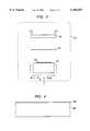
- FIG. 1is a schematic view of the gate region of a typical field effect transistor showing a composite gate electrode made according to the invention
- FIG. 2is a schematic view similar to that of FIG. 1 showing an alternative composite gate electrode made according to the invention
- FIG. 3is a schematic diagram of a PVD apparatus useful for implementing the invention.
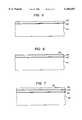
- FIGS. 4-7are schematic representations of a process sequence for forming the composite gate electrode of FIG. 1.
- a silicon substrate 11is shown with field oxide 12 and gate dielectric 13 formed in the conventional manner.
- the composite gate electrodeis shown generally at 16.
- gate dielectric layeris less than 100 Angstroms and preferably less than 60 Angstroms. This is the dimensional regime where depletion problems occur with polysilicon gate electrodes.
- Next in the process sequenceis the formation of the composite gate electrode 16.
- the gate electrodeis illustrated with a single solid outline to convey the fact that in the preferred layered structure of the invention, the materials transition from one to another without a distinct break, and the entire composite gate electrode is made in essentially a single processing operation.
- the composite gate electrodecomprises a tungsten silicide layer, WSi x , 17 deposited on the gate dielectric 13, and a tungsten silicide nitride, WSi x N y , layer 18 deposited on the tungsten silicide layer 17.
- a tungsten silicide layerWSi x , 17 deposited on the gate dielectric 13
- all layersare deposited in one sequential operation, as will later be described.
- the composite gate electrodeis then defined by, e.g., conventional RIE.
- the dielectric 13is shown in FIG. 1 as etched from the source drain regions (using the composite gate electrode 16 as a mask).
- the source and drain 21 and 22are then formed by conventional ion implantation.
- the dielectric layercan remain in place and the source and drain implants made through the dielectric layer using the composite gate electrode as an implant mask.
- the dopantis boron
- the dopantis typically arsenic.
- the gate electrodeis exposed during the implant step and the impurity is implanted into the exposed gate electrode to increase gate conductivity.
- doping of the gateis not needed, and may be avoided.
- the interlevel dielectricis deposited, second level metal is deposited and patterned, and another interlevel dielectric is deposited.
- a third interconnect levelcan be formed.
- the source/drain contact windowsare then opened by conventional lithography, and the source and drain contact metallization is deposited and patterned to form contacts to the source and drain.
- the source and drain contactsare shown schematically at 24 and 25 in FIG. 1. This last series of steps is standard in IC technology and are not illustrated here.
- FIG. 2An alternative embodiment of a composite gate electrode according to the invention is shown in FIG. 2, where the gate electrode 26 is formed of a first layer 27 of WSi x , and a second layer 28 of WSi x N y , as with the device of FIG. 1, but this gate structure has an additional layer of WSi x 29.
- the preferred deposition process for the layers forming the multilayer gate electrodeis physical vapor deposition (PVD), i.e. sputtering.
- PVDphysical vapor deposition
- the tungsten silicide layersare sputtered from a tungsten silicide target in an inert gas atmosphere at reduced pressure.
- the nitride layeris formed by reactive sputtering.
- the multilayer depositions stepsare preferably performed sequentially in the same deposition apparatus, without breaking the vacuum in the PVD apparatus. For the purpose of this description, the layers formed in this manner are defined as formed "in situ".
- Vacuum chamber 31houses the sputtering target 32, (optional) collimator 33, and the substrate heater 34, which supports the wafer 35.
- the gas flowis indicated in the figure and comprises argon for sputtering the metal layers, and argon plus nitrogen for reactively sputtering the nitride layer.
- the silicon substrateis shown at 41 with grown gate dielectric layer 42.
- This viewis of the gate/channel region of the MOS device so the field oxide does not appear.
- the gate dielectricis typically SiO 2 but may be a composite layer of SiO 2 and Si 3 N 4 .
- the gate electrode layersare next deposited.
- FIG. 2The process description below, in conjunction with FIGS. 4-7, is for producing the embodiment shown in FIG. 2, i.e. the three layer gate electrode.
- Producing the structure of FIG. 1involves a straightforward modification of the process for the structure of FIG. 2, i.e. the first tungsten layer is omitted. Other details remain essentially the same.
- the first tungsten silicide layershown at 43 in FIG. 5, is deposited in the PVD reactor using a WSi x target with a Si to W ratio >2.
- the Si/W ratiois >2.5, and the most effective range is 2.5-2.9.
- This layeris optional, as mentioned above, but improves the adhesion between the gate dielectric and the WSi x N y barrier layer to be deposited next.
- Layer 43is deposited in an argon atmosphere at a pressure in the range 2-6 mTorr and a temperature in the range 100-400° C.
- the thickness of layer 43is preferably in the range 100 to 400 ⁇ .
- the barrier layer 44is sputter deposited on layer 43, preferably in situ in the PVD reactor by adding nitrogen to the PVD reactor.
- the barrier layeris WSi x N y , and is a key ingredient in the multilayer gate electrode stack for preventing boron updiffusion from the source/drain regions as outlined earlier.
- the preferred nitrogen flowis between 5 and 55 sccm, with the argon carrier gas flow at 40-60 sccm.
- the silicide/nitride material of layer 44is typically a high resistivity material. The sheet resistance of this material can be controlled by controlling the nitrogen flow rate and the resulting composition of the layer.
- the preferred compositional range for the WSi x N y barrier layeris 5 to 30% N, 40-60% Si, balance W.
- the preferred thickness of layer 44is in the range 50-300 ⁇ .
- the top tungsten silicide layer, 45 in FIG. 7,is formed by turning off the nitrogen flow to the reactor and sputtering non-reactively from the tungsten silicide target in the manner used to form layer 43.
- the thickness of layer 45is in the range 300-1600 Angstroms.
- the nitridemay be deposited in either the nitrided or the non-nitrided mode depending on the nitrogen flow rate. These deposition modes are known in the art. Layers 43-45 can also be deposited by other techniques, such as CVD.
- the silicidecan be formed using dichlorosilane, or similar precursor, and the silicide nitride layer formed by the addition of gases that provide a source of nitrogen. The deposition is then completed by shutting off the nitrogen source to form the top silicide layer.
- the multilayer structure of silicide to silicide-nitride to silicide, or silicide-nitride to silicideconstitutes a compositionally graded stack that allows stress accommodation.
- the ease of fabrication of such a structureis evident by the fact that the whole gate electrode stack can be deposited in one single chamber without the cost of depositing poly-Si and silicide/polycide in separate tools as in the prior art.
- the WSi x N yserves as an excellent barrier for dopant diffusion out of the junctions when the device is subject to thermal treatments while it is being fabricated. Such a barrier is not available in the poly-Si/silicide stacks used in the prior art.
Landscapes
- Chemical & Material Sciences (AREA)
- Engineering & Computer Science (AREA)
- Chemical Kinetics & Catalysis (AREA)
- Materials Engineering (AREA)
- Mechanical Engineering (AREA)
- Metallurgy (AREA)
- Organic Chemistry (AREA)
- Condensed Matter Physics & Semiconductors (AREA)
- Physics & Mathematics (AREA)
- General Physics & Mathematics (AREA)
- Manufacturing & Machinery (AREA)
- Computer Hardware Design (AREA)
- Microelectronics & Electronic Packaging (AREA)
- Power Engineering (AREA)
- Electrodes Of Semiconductors (AREA)
- Insulated Gate Type Field-Effect Transistor (AREA)
Abstract
Description
Claims (14)
Priority Applications (3)
| Application Number | Priority Date | Filing Date | Title |
|---|---|---|---|
| US09/153,522US6103607A (en) | 1998-09-15 | 1998-09-15 | Manufacture of MOSFET devices |
| JP26060099AJP3774088B2 (en) | 1998-09-15 | 1999-09-14 | Fabrication of MOS devices |
| KR1019990039502AKR100632613B1 (en) | 1998-09-15 | 1999-09-15 | MOS type field effect transistor device manufacturing method |
Applications Claiming Priority (1)
| Application Number | Priority Date | Filing Date | Title |
|---|---|---|---|
| US09/153,522US6103607A (en) | 1998-09-15 | 1998-09-15 | Manufacture of MOSFET devices |
Publications (1)
| Publication Number | Publication Date |
|---|---|
| US6103607Atrue US6103607A (en) | 2000-08-15 |
Family
ID=22547572
Family Applications (1)
| Application Number | Title | Priority Date | Filing Date |
|---|---|---|---|
| US09/153,522Expired - LifetimeUS6103607A (en) | 1998-09-15 | 1998-09-15 | Manufacture of MOSFET devices |
Country Status (3)
| Country | Link |
|---|---|
| US (1) | US6103607A (en) |
| JP (1) | JP3774088B2 (en) |
| KR (1) | KR100632613B1 (en) |
Cited By (11)
| Publication number | Priority date | Publication date | Assignee | Title |
|---|---|---|---|---|
| US20040135218A1 (en)* | 2003-01-13 | 2004-07-15 | Zhizhang Chen | MOS transistor with high k gate dielectric |
| US6838376B2 (en)* | 1997-11-05 | 2005-01-04 | Tokyo Electron Limited | Method of forming semiconductor wiring structures |
| US6861356B2 (en) | 1997-11-05 | 2005-03-01 | Tokyo Electron Limited | Method of forming a barrier film and method of forming wiring structure and electrodes of semiconductor device having a barrier film |
| US20050136605A1 (en)* | 2003-12-22 | 2005-06-23 | Murto Robert W. | MOS transistor gates with thin lower metal silicide and methods for making the same |
| US20050191803A1 (en)* | 1997-11-05 | 2005-09-01 | Tokyo Electron Limited | Method of forming a metal film for electrode |
| US20060244045A1 (en)* | 2003-09-30 | 2006-11-02 | Mark Visokay | MOS Transistor Gates with Doped Silicide and Methods for Making the Same |
| US20070161260A1 (en)* | 2003-07-07 | 2007-07-12 | Vaartstra Brian A | Methods of forming a phosphorus doped silicon dioxide-comprising layer |
| US20080284025A1 (en)* | 2005-03-07 | 2008-11-20 | Qi Pan | Electrically Conductive Line |
| US7465660B2 (en)* | 2000-06-15 | 2008-12-16 | Stmicroelectronics, Inc. | Graded/stepped silicide process to improve MOS transistor |
| CN108292596A (en)* | 2015-09-11 | 2018-07-17 | 应用材料公司 | Tungsten nitride silicon nitride film and its forming method |
| US10164044B2 (en)* | 2015-04-16 | 2018-12-25 | Micron Technology, Inc. | Gate stacks |
Families Citing this family (2)
| Publication number | Priority date | Publication date | Assignee | Title |
|---|---|---|---|---|
| KR100331861B1 (en)* | 2000-07-21 | 2002-04-09 | Hynix Semiconductor Inc | Method for fabricating gate electrode of semiconductor device |
| WO2007116982A1 (en)* | 2006-04-06 | 2007-10-18 | Nec Corporation | Semiconductor device, and its manufacturing method |
Citations (8)
| Publication number | Priority date | Publication date | Assignee | Title |
|---|---|---|---|---|
| US5049954A (en)* | 1988-12-07 | 1991-09-17 | Kabushiki Kaisha Toshiba | GaAs field effect semiconductor device having Schottky gate structure |
| US5164333A (en)* | 1990-06-19 | 1992-11-17 | Siemens Aktiengesellschaft | Method for manufacturing a multi-layer gate electrode for a mos transistor |
| US5436489A (en)* | 1993-03-24 | 1995-07-25 | Mitsubishi Denki Kabushiki Kaisha | Field effect transistor |
| US5648668A (en)* | 1994-11-01 | 1997-07-15 | Mitsubishi Denki Kabushiki Kaisha | High breakdown voltage field effect transistor |
| US5872057A (en)* | 1996-11-22 | 1999-02-16 | Taiwan Semiconductor Manufacturing Co., Ltd. | Method of forming oxide dielectric layer on refractory metal silicide gate |
| US5907784A (en)* | 1996-02-26 | 1999-05-25 | Cypress Semiconductor | Method of making multi-layer gate structure with different stoichiometry silicide layers |
| US5933741A (en)* | 1997-08-18 | 1999-08-03 | Vanguard International Semiconductor Corporation | Method of making titanium silicide source/drains and tungsten silicide gate electrodes for field effect transistors |
| US5956585A (en)* | 1997-02-19 | 1999-09-21 | Winbond Electronics Corporation | Method of forming a self-aligned damage-free buried contact |
Family Cites Families (3)
| Publication number | Priority date | Publication date | Assignee | Title |
|---|---|---|---|---|
| JP2692590B2 (en)* | 1994-06-29 | 1997-12-17 | 日本電気株式会社 | Semiconductor device and manufacturing method thereof |
| JPH08264484A (en)* | 1995-03-20 | 1996-10-11 | Nippon Telegr & Teleph Corp <Ntt> | Semiconductor device |
| KR0156216B1 (en)* | 1995-08-29 | 1998-10-15 | 구자홍 | Fabricating method of thin film transistor |
- 1998
- 1998-09-15USUS09/153,522patent/US6103607A/ennot_activeExpired - Lifetime
- 1999
- 1999-09-14JPJP26060099Apatent/JP3774088B2/ennot_activeExpired - Fee Related
- 1999-09-15KRKR1019990039502Apatent/KR100632613B1/ennot_activeExpired - Fee Related
Patent Citations (8)
| Publication number | Priority date | Publication date | Assignee | Title |
|---|---|---|---|---|
| US5049954A (en)* | 1988-12-07 | 1991-09-17 | Kabushiki Kaisha Toshiba | GaAs field effect semiconductor device having Schottky gate structure |
| US5164333A (en)* | 1990-06-19 | 1992-11-17 | Siemens Aktiengesellschaft | Method for manufacturing a multi-layer gate electrode for a mos transistor |
| US5436489A (en)* | 1993-03-24 | 1995-07-25 | Mitsubishi Denki Kabushiki Kaisha | Field effect transistor |
| US5648668A (en)* | 1994-11-01 | 1997-07-15 | Mitsubishi Denki Kabushiki Kaisha | High breakdown voltage field effect transistor |
| US5907784A (en)* | 1996-02-26 | 1999-05-25 | Cypress Semiconductor | Method of making multi-layer gate structure with different stoichiometry silicide layers |
| US5872057A (en)* | 1996-11-22 | 1999-02-16 | Taiwan Semiconductor Manufacturing Co., Ltd. | Method of forming oxide dielectric layer on refractory metal silicide gate |
| US5956585A (en)* | 1997-02-19 | 1999-09-21 | Winbond Electronics Corporation | Method of forming a self-aligned damage-free buried contact |
| US5933741A (en)* | 1997-08-18 | 1999-08-03 | Vanguard International Semiconductor Corporation | Method of making titanium silicide source/drains and tungsten silicide gate electrodes for field effect transistors |
Cited By (15)
| Publication number | Priority date | Publication date | Assignee | Title |
|---|---|---|---|---|
| US6838376B2 (en)* | 1997-11-05 | 2005-01-04 | Tokyo Electron Limited | Method of forming semiconductor wiring structures |
| US6861356B2 (en) | 1997-11-05 | 2005-03-01 | Tokyo Electron Limited | Method of forming a barrier film and method of forming wiring structure and electrodes of semiconductor device having a barrier film |
| US7829144B2 (en) | 1997-11-05 | 2010-11-09 | Tokyo Electron Limited | Method of forming a metal film for electrode |
| US20050191803A1 (en)* | 1997-11-05 | 2005-09-01 | Tokyo Electron Limited | Method of forming a metal film for electrode |
| US7465660B2 (en)* | 2000-06-15 | 2008-12-16 | Stmicroelectronics, Inc. | Graded/stepped silicide process to improve MOS transistor |
| US20040135218A1 (en)* | 2003-01-13 | 2004-07-15 | Zhizhang Chen | MOS transistor with high k gate dielectric |
| US7790632B2 (en) | 2003-07-07 | 2010-09-07 | Micron Technology, Inc. | Methods of forming a phosphorus doped silicon dioxide-comprising layer |
| US20070161260A1 (en)* | 2003-07-07 | 2007-07-12 | Vaartstra Brian A | Methods of forming a phosphorus doped silicon dioxide-comprising layer |
| US20060244045A1 (en)* | 2003-09-30 | 2006-11-02 | Mark Visokay | MOS Transistor Gates with Doped Silicide and Methods for Making the Same |
| US7045456B2 (en)* | 2003-12-22 | 2006-05-16 | Texas Instruments Incorporated | MOS transistor gates with thin lower metal silicide and methods for making the same |
| US20050136605A1 (en)* | 2003-12-22 | 2005-06-23 | Murto Robert W. | MOS transistor gates with thin lower metal silicide and methods for making the same |
| US20080284025A1 (en)* | 2005-03-07 | 2008-11-20 | Qi Pan | Electrically Conductive Line |
| US10164044B2 (en)* | 2015-04-16 | 2018-12-25 | Micron Technology, Inc. | Gate stacks |
| US10777651B2 (en) | 2015-04-16 | 2020-09-15 | Micron Technology, Inc. | Gate stacks |
| CN108292596A (en)* | 2015-09-11 | 2018-07-17 | 应用材料公司 | Tungsten nitride silicon nitride film and its forming method |
Also Published As
| Publication number | Publication date |
|---|---|
| KR100632613B1 (en) | 2006-10-09 |
| KR20000023176A (en) | 2000-04-25 |
| JP2000091579A (en) | 2000-03-31 |
| JP3774088B2 (en) | 2006-05-10 |
Similar Documents
| Publication | Publication Date | Title |
|---|---|---|
| US5767004A (en) | Method for forming a low impurity diffusion polysilicon layer | |
| US6770571B2 (en) | Barrier in gate stack for improved gate dielectric integrity | |
| US5364803A (en) | Method of preventing fluorine-induced gate oxide degradation in WSix polycide structure | |
| US5923999A (en) | Method of controlling dopant diffusion and metal contamination in thin polycide gate conductor of mosfet device | |
| US7172955B2 (en) | Silicon composition in CMOS gates | |
| JP2978736B2 (en) | Method for manufacturing semiconductor device | |
| US6730584B2 (en) | Methods for forming wordlines, transistor gates, and conductive interconnects, and wordline, transistor gate, and conductive interconnect structures | |
| US6093589A (en) | Methods for preventing gate oxide degradation | |
| US20020113294A1 (en) | CMOS semiconductor device and method of manufacturing the same | |
| US6103607A (en) | Manufacture of MOSFET devices | |
| US5940725A (en) | Semiconductor device with non-deposited barrier layer | |
| US6879043B2 (en) | Electrode structure and method for fabricating the same | |
| US7122870B2 (en) | Methods of forming a multilayer stack alloy for work function engineering | |
| US8304333B2 (en) | Method of forming a high-k gate dielectric layer | |
| US6339246B1 (en) | Tungsten silicide nitride as an electrode for tantalum pentoxide devices | |
| US6403458B2 (en) | Method for fabricating local interconnect structure for integrated circuit devices, source structures | |
| JPH1093077A (en) | Semiconductor device and manufacturing method thereof | |
| US6599820B1 (en) | Method of producing a semiconductor device | |
| KR100764341B1 (en) | Manufacturing method of semiconductor device | |
| KR100364524B1 (en) | Method for Forming MOS Transistor Having Single-Layer Gate Structure Made of Tungsten Silicide | |
| US6555887B1 (en) | Semiconductor device with multi-layer interconnection | |
| KR100744642B1 (en) | Metallization of Semiconductor Devices, Gate Electrodes of Semiconductor Devices, and Formation Methods | |
| KR19990008624A (en) | Polycrystalline silicon gate having refractory conductive layer and method of forming the same |
Legal Events
| Date | Code | Title | Description |
|---|---|---|---|
| AS | Assignment | Owner name:LUCENT TECHNOLOGIES INC., NEW JERSEY Free format text:ASSIGNMENT OF ASSIGNORS INTEREST;ASSIGNORS:KIZILYALLI, ISIK C.;MERCHANT, SAILESH MANSINH;ROY, PRADIP KUMAR;REEL/FRAME:009475/0635 Effective date:19980911 | |
| STCF | Information on status: patent grant | Free format text:PATENTED CASE | |
| FEPP | Fee payment procedure | Free format text:PAYOR NUMBER ASSIGNED (ORIGINAL EVENT CODE: ASPN); ENTITY STATUS OF PATENT OWNER: LARGE ENTITY | |
| FPAY | Fee payment | Year of fee payment:4 | |
| FPAY | Fee payment | Year of fee payment:8 | |
| FPAY | Fee payment | Year of fee payment:12 | |
| AS | Assignment | Owner name:DEUTSCHE BANK AG NEW YORK BRANCH, AS COLLATERAL AG Free format text:PATENT SECURITY AGREEMENT;ASSIGNORS:LSI CORPORATION;AGERE SYSTEMS LLC;REEL/FRAME:032856/0031 Effective date:20140506 | |
| AS | Assignment | Owner name:AVAGO TECHNOLOGIES GENERAL IP (SINGAPORE) PTE. LTD Free format text:ASSIGNMENT OF ASSIGNORS INTEREST;ASSIGNOR:AGERE SYSTEMS LLC;REEL/FRAME:035365/0634 Effective date:20140804 | |
| AS | Assignment | Owner name:AGERE SYSTEMS LLC, PENNSYLVANIA Free format text:TERMINATION AND RELEASE OF SECURITY INTEREST IN PATENT RIGHTS (RELEASES RF 032856-0031);ASSIGNOR:DEUTSCHE BANK AG NEW YORK BRANCH, AS COLLATERAL AGENT;REEL/FRAME:037684/0039 Effective date:20160201 Owner name:LSI CORPORATION, CALIFORNIA Free format text:TERMINATION AND RELEASE OF SECURITY INTEREST IN PATENT RIGHTS (RELEASES RF 032856-0031);ASSIGNOR:DEUTSCHE BANK AG NEW YORK BRANCH, AS COLLATERAL AGENT;REEL/FRAME:037684/0039 Effective date:20160201 | |
| AS | Assignment | Owner name:BANK OF AMERICA, N.A., AS COLLATERAL AGENT, NORTH CAROLINA Free format text:PATENT SECURITY AGREEMENT;ASSIGNOR:AVAGO TECHNOLOGIES GENERAL IP (SINGAPORE) PTE. LTD.;REEL/FRAME:037808/0001 Effective date:20160201 Owner name:BANK OF AMERICA, N.A., AS COLLATERAL AGENT, NORTH Free format text:PATENT SECURITY AGREEMENT;ASSIGNOR:AVAGO TECHNOLOGIES GENERAL IP (SINGAPORE) PTE. LTD.;REEL/FRAME:037808/0001 Effective date:20160201 | |
| AS | Assignment | Owner name:AVAGO TECHNOLOGIES GENERAL IP (SINGAPORE) PTE. LTD., SINGAPORE Free format text:TERMINATION AND RELEASE OF SECURITY INTEREST IN PATENTS;ASSIGNOR:BANK OF AMERICA, N.A., AS COLLATERAL AGENT;REEL/FRAME:041710/0001 Effective date:20170119 Owner name:AVAGO TECHNOLOGIES GENERAL IP (SINGAPORE) PTE. LTD Free format text:TERMINATION AND RELEASE OF SECURITY INTEREST IN PATENTS;ASSIGNOR:BANK OF AMERICA, N.A., AS COLLATERAL AGENT;REEL/FRAME:041710/0001 Effective date:20170119 | |
| AS | Assignment | Owner name:BELL SEMICONDUCTOR, LLC, ILLINOIS Free format text:ASSIGNMENT OF ASSIGNORS INTEREST;ASSIGNORS:AVAGO TECHNOLOGIES GENERAL IP (SINGAPORE) PTE. LTD.;BROADCOM CORPORATION;REEL/FRAME:044886/0001 Effective date:20171208 | |
| AS | Assignment | Owner name:CORTLAND CAPITAL MARKET SERVICES LLC, AS COLLATERA Free format text:SECURITY INTEREST;ASSIGNORS:HILCO PATENT ACQUISITION 56, LLC;BELL SEMICONDUCTOR, LLC;BELL NORTHERN RESEARCH, LLC;REEL/FRAME:045216/0020 Effective date:20180124 | |
| AS | Assignment | Owner name:BELL NORTHERN RESEARCH, LLC, ILLINOIS Free format text:SECURITY INTEREST;ASSIGNOR:CORTLAND CAPITAL MARKET SERVICES LLC;REEL/FRAME:060885/0001 Effective date:20220401 Owner name:BELL SEMICONDUCTOR, LLC, ILLINOIS Free format text:SECURITY INTEREST;ASSIGNOR:CORTLAND CAPITAL MARKET SERVICES LLC;REEL/FRAME:060885/0001 Effective date:20220401 Owner name:HILCO PATENT ACQUISITION 56, LLC, ILLINOIS Free format text:SECURITY INTEREST;ASSIGNOR:CORTLAND CAPITAL MARKET SERVICES LLC;REEL/FRAME:060885/0001 Effective date:20220401 |