US6102896A - Disposable injector device - Google Patents
Disposable injector deviceDownload PDFInfo
- Publication number
- US6102896A US6102896AUS09/392,293US39229399AUS6102896AUS 6102896 AUS6102896 AUS 6102896AUS 39229399 AUS39229399 AUS 39229399AUS 6102896 AUS6102896 AUS 6102896A
- Authority
- US
- United States
- Prior art keywords
- plunger
- section
- injector device
- barrel
- cap
- Prior art date
- Legal status (The legal status is an assumption and is not a legal conclusion. Google has not performed a legal analysis and makes no representation as to the accuracy of the status listed.)
- Expired - Fee Related
Links
Images


Classifications
- A—HUMAN NECESSITIES
- A61—MEDICAL OR VETERINARY SCIENCE; HYGIENE
- A61M—DEVICES FOR INTRODUCING MEDIA INTO, OR ONTO, THE BODY; DEVICES FOR TRANSDUCING BODY MEDIA OR FOR TAKING MEDIA FROM THE BODY; DEVICES FOR PRODUCING OR ENDING SLEEP OR STUPOR
- A61M37/00—Other apparatus for introducing media into the body; Percutany, i.e. introducing medicines into the body by diffusion through the skin
- A61M37/0069—Devices for implanting pellets, e.g. markers or solid medicaments
- A—HUMAN NECESSITIES
- A61—MEDICAL OR VETERINARY SCIENCE; HYGIENE
- A61M—DEVICES FOR INTRODUCING MEDIA INTO, OR ONTO, THE BODY; DEVICES FOR TRANSDUCING BODY MEDIA OR FOR TAKING MEDIA FROM THE BODY; DEVICES FOR PRODUCING OR ENDING SLEEP OR STUPOR
- A61M5/00—Devices for bringing media into the body in a subcutaneous, intra-vascular or intramuscular way; Accessories therefor, e.g. filling or cleaning devices, arm-rests
- A61M5/178—Syringes
- A61M5/28—Syringe ampoules or carpules, i.e. ampoules or carpules provided with a needle
- A—HUMAN NECESSITIES
- A61—MEDICAL OR VETERINARY SCIENCE; HYGIENE
- A61M—DEVICES FOR INTRODUCING MEDIA INTO, OR ONTO, THE BODY; DEVICES FOR TRANSDUCING BODY MEDIA OR FOR TAKING MEDIA FROM THE BODY; DEVICES FOR PRODUCING OR ENDING SLEEP OR STUPOR
- A61M5/00—Devices for bringing media into the body in a subcutaneous, intra-vascular or intramuscular way; Accessories therefor, e.g. filling or cleaning devices, arm-rests
- A61M5/178—Syringes
- A61M5/30—Syringes for injection by jet action, without needle, e.g. for use with replaceable ampoules or carpules
- A—HUMAN NECESSITIES
- A61—MEDICAL OR VETERINARY SCIENCE; HYGIENE
- A61M—DEVICES FOR INTRODUCING MEDIA INTO, OR ONTO, THE BODY; DEVICES FOR TRANSDUCING BODY MEDIA OR FOR TAKING MEDIA FROM THE BODY; DEVICES FOR PRODUCING OR ENDING SLEEP OR STUPOR
- A61M5/00—Devices for bringing media into the body in a subcutaneous, intra-vascular or intramuscular way; Accessories therefor, e.g. filling or cleaning devices, arm-rests
- A61M5/178—Syringes
- A61M5/31—Details
- A61M5/315—Pistons; Piston-rods; Guiding, blocking or restricting the movement of the rod or piston; Appliances on the rod for facilitating dosing ; Dosing mechanisms
- A61M5/31501—Means for blocking or restricting the movement of the rod or piston
- A61M2005/31508—Means for blocking or restricting the movement of the rod or piston provided on the piston-rod
- A—HUMAN NECESSITIES
- A61—MEDICAL OR VETERINARY SCIENCE; HYGIENE
- A61M—DEVICES FOR INTRODUCING MEDIA INTO, OR ONTO, THE BODY; DEVICES FOR TRANSDUCING BODY MEDIA OR FOR TAKING MEDIA FROM THE BODY; DEVICES FOR PRODUCING OR ENDING SLEEP OR STUPOR
- A61M5/00—Devices for bringing media into the body in a subcutaneous, intra-vascular or intramuscular way; Accessories therefor, e.g. filling or cleaning devices, arm-rests
- A61M5/178—Syringes
- A61M5/24—Ampoule syringes, i.e. syringes with needle for use in combination with replaceable ampoules or carpules, e.g. automatic
- A61M5/2422—Ampoule syringes, i.e. syringes with needle for use in combination with replaceable ampoules or carpules, e.g. automatic using emptying means to expel or eject media, e.g. pistons, deformation of the ampoule, or telescoping of the ampoule
- A61M5/2429—Ampoule syringes, i.e. syringes with needle for use in combination with replaceable ampoules or carpules, e.g. automatic using emptying means to expel or eject media, e.g. pistons, deformation of the ampoule, or telescoping of the ampoule by telescoping of ampoules or carpules with the syringe body
- A—HUMAN NECESSITIES
- A61—MEDICAL OR VETERINARY SCIENCE; HYGIENE
- A61M—DEVICES FOR INTRODUCING MEDIA INTO, OR ONTO, THE BODY; DEVICES FOR TRANSDUCING BODY MEDIA OR FOR TAKING MEDIA FROM THE BODY; DEVICES FOR PRODUCING OR ENDING SLEEP OR STUPOR
- A61M5/00—Devices for bringing media into the body in a subcutaneous, intra-vascular or intramuscular way; Accessories therefor, e.g. filling or cleaning devices, arm-rests
- A61M5/42—Devices for bringing media into the body in a subcutaneous, intra-vascular or intramuscular way; Accessories therefor, e.g. filling or cleaning devices, arm-rests having means for desensitising skin, for protruding skin to facilitate piercing, or for locating point where body is to be pierced
- A61M5/422—Desensitising skin
- A—HUMAN NECESSITIES
- A61—MEDICAL OR VETERINARY SCIENCE; HYGIENE
- A61M—DEVICES FOR INTRODUCING MEDIA INTO, OR ONTO, THE BODY; DEVICES FOR TRANSDUCING BODY MEDIA OR FOR TAKING MEDIA FROM THE BODY; DEVICES FOR PRODUCING OR ENDING SLEEP OR STUPOR
- A61M5/00—Devices for bringing media into the body in a subcutaneous, intra-vascular or intramuscular way; Accessories therefor, e.g. filling or cleaning devices, arm-rests
- A61M5/46—Devices for bringing media into the body in a subcutaneous, intra-vascular or intramuscular way; Accessories therefor, e.g. filling or cleaning devices, arm-rests having means for controlling depth of insertion
- A—HUMAN NECESSITIES
- A61—MEDICAL OR VETERINARY SCIENCE; HYGIENE
- A61M—DEVICES FOR INTRODUCING MEDIA INTO, OR ONTO, THE BODY; DEVICES FOR TRANSDUCING BODY MEDIA OR FOR TAKING MEDIA FROM THE BODY; DEVICES FOR PRODUCING OR ENDING SLEEP OR STUPOR
- A61M5/00—Devices for bringing media into the body in a subcutaneous, intra-vascular or intramuscular way; Accessories therefor, e.g. filling or cleaning devices, arm-rests
- A61M5/48—Devices for bringing media into the body in a subcutaneous, intra-vascular or intramuscular way; Accessories therefor, e.g. filling or cleaning devices, arm-rests having means for varying, regulating, indicating or limiting injection pressure
- A61M5/482—Varying injection pressure, e.g. by varying speed of injection
Definitions
- This inventionis directed generally to injector devices, and specifically to a disposable injector device operating by hand force and having a snap means such as break tabs or a snap ring to release the plunger section abruptly as a snap point is reached.
- parenteral injectionsAn additional problem with parenteral injections is that only a few drugs or vaccines are available in the form of injection-ready, stable liquids. The great majority of parenteral preparations are freeze-dried and require dilution before injection. The great majority also require constant refrigeration during storage.
- Some single-use injectorsare designed to self-destruct, eliminating the temptation to re-use. Examples are disclosed in U.S. Pat. Nos. 3,998,224 to Chiquiar-Arias, 4,233,975 to Yerman, and 4,391,272 to Staempfli. Another example is the SoloshotTM syringe (manufactured by Becton Dickinson). These syringes are more expensive than standard syringes, and also require medical expertise to use.
- breakable tabs and snap ringsin plastic containers, such as bottles, is well known. These devices are commonly used for tamper protection, sealing, and the like.
- An early exampleis disclosed in U.S. Pat. No. 3,407,956 to Linkletter, which shows a removable and replaceable bottle cap.
- the plastic caphas an annular beaded molded on the inside, which overrides a similar bead molded on the outside of the neck of the bottle. Natural elasticity of the materials used in manufacturing the cap permit it to expand temporarily. This allows the beads to override and then to contract again immediately once the beads have passed each other. This seats the cap firmly on the container and provides a good seal.
- Needleless injectorsare well known. These injectors use a fine stream of pressurized liquid to penetrate the skin. The pain is considerably less than that experienced during a conventional injection. Early designs used high pressure throughout the injection. Later, it was realized that high pressure was required only at the start of the injection, to punch a hole through the tough epidermis. The bulk of the injection could then be infused along the initial track under much lower pressure. U.S. Pat. No. 2,704,542 to Scherer and 3,908,651 to Fudge disclose examples of this design. The engineering demands of changing the pressure during the injection and resulting complexity have limited the use of such injectors.
- Standard high-pressure needleless jet injectorsare also inherently complex, requiring precision engineering with dozens of machined steel parts. Most designs have focused on the production of robust, reliable, heavy-duty machines capable of many injections at high rates for mass immunization campaigns. Infection due to cross-contamination in such jet injectors has been reported. This may be due to the high pressures caused in the tissues. As the distended tissue relaxes and the pressure simultaneously falls in the injector, liquid can be sucked into the injector. This liquid may be contaminated with blood or interstitial fluid. This problem has been addressed by the development of single-use vials which insert into the jet injector. This approach may be combined with a replaceable nozzle and a vaccine fluid path of cheap plastic, as disclosed in U.S. Pat. 4,266,541 to Landau.
- a mono-dose disposable jet injectorhas been developed under the trademark "Intraject” by Weston Medical, UK. Similar to other jet injectors, this injector uses a highly compressed gas in a canister to propel the vaccine dose. See Lloyd J. S., Aguado M. T., Pre-Filled Monodose Injection Devices: A safety standard for new vaccines, or a revolution in the delivery of immunizations?, Global Programme on Vaccines and Immunization, World Health Organization, May 1998.
- Trehaloseis one example. See U.S. Pat. No. 4,891,319 to Roser, and Colaco C., Sen S., Thangavelu M., Pinder S., and Roser, B. J., Extraordinary stability of enzymes dried in trehalose: Simplified molecular biology. Biotechnol. 10 1007-1011 (1992). A similar technique can be applied to stabilized vaccines. See Gribbon E. M., Sen S., Roser B. J. and Kampinga J., Stabilisation of Vaccines Using Trehalose (Q-T4) Technology, in F. Brown, (ed) New Approaches to Stabilisation of Vaccine Potency Dev Biol Stand Basel Karger 87 193-199 (1996).
- Phosphate glassesare also suitable for stabilization of parenteral medications. See U.S. Pat. No. 4,698,318 to Vogel et al. Phosphate glasses are typically much stronger than sugar glasses. Because of their strength, phosphate glasses are often used as structural elements in bone repair. Mixtures of metal carboxylates such as the acetate salts of sodium, potassium, calcium and zinc also form excellent glasses, PCT Publication No WO90/11756). By using different mixtures of the individual carboxylates and by using different metal cations, it is possible to tailor these phosphate and carboxylate glasses to dissolve at different, specific rates in body fluids. Being composed of simple chemicals normally prevalent in the body, phosphate and carboxylate glasses exhibit very low toxicity.
- the present inventionis a single use injector device for injecting parenteral medications which operates by hand force.
- the injector devicehas a plunger section and a base.
- a snap meanssuch as break tabs or a snap ring resists its motion toward the patient's skin surface.
- the snap meansreleases abruptly as the hand force reaches a snap point.
- the motion of the moving portionthen drives the medication through the skin surface and into the body of the patient.
- the medicationis in liquid form, the actual injection may be carried out through a hollow needle attached to the plunger section.
- the suddenly increased pressure of the medication at the snap pointmay be used to form a liquid jet for needleless injection.
- Part or all of the medicationmay be contained in a glass needle which dissolves in the body after injection.
- the injector devicerequires little training to use, reduces perceived pain, and improves injection safety.
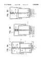
- FIG. 1is a cross-sectional view of an injector device in the initial position, taken parallel to the longitudinal axis, the device having break tabs, a needle, and a barrel containing liquid medication.
- FIGS. 2A, 2B, and 2Care cross-sectional views of the injector device of FIG. 1, showing in succession the penetration of the skin by the needle, the injection of the liquid medication, and needle withdrawal.
- FIGS. 3A, 3B, and 3Care cross-sectional views of an injector device having a shaft for injection of a glass needle, and show in succession the initial position, the injection of the glass needle, and the withdrawal of the shaft.
- FIGS. 4A and 4Bare cross-sectional views of an injector device having a tubular shaft for injection of a glass needle along with liquid medication, showing in succession the initial position and the withdrawal of the shaft after the liquid medication is injected along the glass needle track.
- FIG. 5is a cross-sectional view of an injector device in the initial position, the injector device having jet injection and a plunger which is struck by a cap after the snap point is reached.
- FIGS. 6A, 6B, and 6Care cross-sectional views of an injector device having jet injection means, showing in succession the breaking of the break tabs, the formation of the liquid jet, and the completed injection.
- FIGS. 7A and 7Bare cross-sectional views of an injector device having a snap ring and jet injection, showing in succession the initial position and the completed injection.
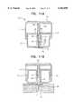
- FIG. 8is a cross-sectional view of an injector device in the initial position, having a barrel between the cap and the plunger.
- FIGS. 9A, 9B, 9C, and 9Dare cross-sectional views of an injector device in which the hand force is applied directly to the plunger, having a hollow needle for injection of liquid medication, and showing in succession the initial position, penetration of the hollow needle, injection of the medication, and withdrawal of the needle.
- FIGS. 10A, 10B, 10C, and 10Dare cross-sectional views of an injector device in which the hand force is applied directly to the plunger, having a shaft for injection of a glass needle, and showing in succession the packaged injector device, the initial position, the injection of the glass needle, and withdrawal of the shaft.
- FIGS. 11A and 11Bare cross-sectional views of an injector device having a tubular shaft for injection of a glass needle, the tubular shaft having perforations for injection of liquid medication from the cavity.
- the present inventionis a single use injector device 10 for injecting parenteral medications into the body of a patient.
- the injector deviceoperates by hand force, without requiring any other force to complete the injection.
- the injector device 10has a plunger section 12 and a base 14.
- a snap meanssuch as break tabs or a snap ring resists its motion toward the patient's skin surface 16. See FIGS. 1 and 2.
- the snap meansreleases abruptly as the hand force reaches a snap point. The same motion of the moving portion then drives the medication through the skin surface 16 and into the body of the patient.
- a variety of injection meansmay be used for the actual injection of the medication. If the medication is in liquid form, the injection may be carried out through a hollow needle 18 attached to the plunger section 12. Alternatively, the suddenly increased pressure of the medication at the snap point may be used to form a liquid jet 20 for needleless injection, as in FIG. 6B. Part or all of the medication may be contained in a glass needle 22 which dissolves in the body after injection, as in FIG. 3C.
- the plunger section 12includes a plunger 24.
- the plunger sectionis at least partially composed of plastic, preferably completely composed of plastic.
- the plunger 24has a longitudinal axis A, as shown in FIG. 1.
- the plunger 24also has a first end 26 and a second end 28.
- the first endhas a periphery 29.
- the plungerpreferably has a circular cross-section (taken perpendicular to the longitudinal axis).
- the plungermay have a uniform diameter from the first end 26 to the second end 28, as shown in FIGS. 11A and 11B.
- the plungermay have a central section 30 which is narrower than the first end 26, as shown in FIGS. 1 and 8.
- the central section 30may be narrower than either the first end 26 or the second end 28, as in FIG. 9A.
- the first end 26 of the plungeris the end which contacts the medication in the reservoir means.
- the plunger section 12may include a barrel 34, as shown in FIGS. 1-2C and 4A-9D.
- the barrel 34is tubular and preferably has a circular cross-section.
- the barrelhas a first end 36 and a second end 38.
- the first end 36is at least partially closed, so that the barrel is cup-shaped.
- the barrel 34has a reservoir 40 adapted to contain the liquid medication 32.
- the longitudinal axis of the barrelis coincident with the longitudinal axis of the plunger 24.
- the barrelhas an inner surface 42 and an outer surface 44.
- the barrel 34is located at least partially within the cavity 46 of the base 14.
- the shape of the barrel in cross sectioncorresponds to the shape of the plunger, so that a snug sliding fit is produced.
- the barrel 34slides with respect to the cavity 46, parallel to the longitudinal axis of the cavity.
- the injector deviceincludes a barrel 34
- the first end 26 of the plungeris located within the barrel, both in the initial position and during the injection.
- the first end 26contacts the liquid medication 32.
- the periphery 29 of the first end 26 of the plungerforms a liquid-tight, sliding seal with the inner surface 42 of the barrel.
- the plunger 24slides with respect to the barrel 34 parallel to the longitudinal axis of the plunger.
- the motion of the moving portion of the plunger section 12 toward the skin surface 16 after the snap point is reachedexpels the liquid medication from the reservoir 40 and injects the liquid medication 32 into the body of the patient.
- the sliding barrelallows the injection of a liquid medication to be carefully controlled in stages, and helps to make injections easy to do correctly, even for a minimally trained health worker.
- the injector devicecontains a single dose of the liquid medication, such as a drug or a vaccine.
- the liquid medicationmay be a stable form, so that refrigeration is not required. If the liquid medication is unstable, the injector devices can be refrigerated.
- the injector device 10can be pre-filled with sterile formulations of a very wide range of active solutions and suspensions. The injector device is ideally suited to bulk manufacture, distribution and delivery of vaccines and drugs for human and veterinary use.
- the base 14is generally tubular and has a plunger end 48, a nozzle end 50, and an outer surface 52.
- the baseis at least partially composed of plastic, and preferably entirely composed of plastic.
- the plasticis preferably opaque or translucent, particularly if any injection means involving a needle is used.
- the base and plunger sectioncan be easily constructed using inexpensive plastic injection molding technology, making the injector device sufficiently cheap to be disposable.
- the plasticmay be sterilizable by heat, radiation, or chemicals.
- the cavity 46 of the basehas a nozzle end 54 and a cavity surface 56.
- the longitudinal axis of the cavity 46is coincident with the longitudinal axis of the plunger.
- the plunger 24is located at least partially within the cavity.
- the plungerslides within the cavity parallel to the longitudinal axis of the cavity. If a barrel is used, the barrel is located between the plunger 24 and the cavity surface 56.
- the baseincludes a bore 57, of smaller diameter than the cavity, extending between the nozzle end 54 of the cavity and the nozzle end 50 of the base.
- the injector devicehas snap means for resisting movement of at least a moving portion of the plunger section from an initial position toward the skin surface as the hand force is applied to the moving portion.
- the entire plunger sectionis the moving portion.
- the snap meansreleases the moving portion of the plunger section abruptly as the snap point is reached. After the snap point is reached the moving portion of the plunger section moves rapidly toward the skin surface.
- the snap pointis reached when the hand force is 2N-100 N, preferably 10-40 N, most preferably 20-30 N. A breaking force significantly smaller than this may not complete the injection rapidly enough for optimum patient comfort; a larger force may be difficult for a health worker to exert.
- the plunger sectionremains essentially stationary up to the snap point, since the snap means holds it back. At the snap point the hand force is automatically and abruptly switched from overcoming the snap means to accelerating the moving portion of the plunger section.
- the plunger sectionis light in weight, typically only a few grams, and resistance to the motion is small. A very rapid acceleration therefore results.
- the injectionoccurs within a very short space of time after the snap point, typically a fraction of a second.
- the snap meansdiffers from previous use of springs to provide power for an injection, as in EP0595508 to Alchas et al. Such a spring does not initially resist hand pressure, and then suddenly snap.
- the snap means of the present inventiondoes not require a trigger to release it; rather it releases automatically as the breaking strength of a break tab is reached, or as the limit of elastic deformation is reached for a snap ring. A continuous motion of the hand both snaps the snap means and completes the injection.
- the snap meansdoes not include a spring. Springs may be used in the injector device as part of mechanisms other than the snap means, such as for withdrawal of a needle.
- the moving portion of the plunger sectionincludes the plunger 24 and the barrel. Their motion may not be exactly simultaneous; either the plunger or the barrel may move first after the snap point.
- the barrelmay be oriented with the first end 36 up (further from the skin surface), as in FIG. 8, or with the first end down (closer to the skin surface), as in FIGS. 1 and 5.
- the first end 36 of the barrelis located between the first end 26 of the plunger and the nozzle end 54 of the cavity.
- the plunger 24is located between the first end 36 of the barrel and the nozzle end 54 of the cavity.
- the moving portion of the plunger sectionincludes the plunger.
- the first end 26 of the plungeris located within the cavity 46.
- the periphery 29 of the first end of the plungercontacts the cavity surface 56, instead of the inner surface of the barrel 42.
- injection means for injecting the medicationare suited for use with the injector device.
- the various injection mechanismshave in common that the abrupt motion of the moving portion of the plunger section toward the skin surface after the snap point is reached drives the medication through the skin surface and into the body of the patient.
- Somewhat different injection meansare required for injecting liquid medications, solid medications (such as glass needles), and combinations of liquid and solid medications.
- the injector device 10may include a reservoir means for containing the liquid medication.
- the reservoir meansmay be the reservoir 40 if a barrel is used, or the cavity 46 if no barrel is used.
- the deviceis pre-loaded with sterile liquid in the factory.
- the liquid medicationcan be a conventional liquid formulation of a drug or vaccine, which would require that the device be refrigerated.
- a stable non-aqueous ready-to-inject liquid suspensionis used, as described in PCT application WO98/41188 and U.S. patent application Ser. No. 09/271,204, so that no refrigeration is required.
- a hollow needle 18may be part of the injection means, as shown diagrammatically in FIGS. 1, 2A-2C, and 9A-9D.
- the hollow needleis preferably made of steel, and is a sliding fit in the bore 57.
- the hollow needleis tubular and has an attachment end 58 and a free end 60.
- the attachment end 58is attached to the plunger section 12.
- the free end 60is sharp, in the conventional manner.
- the interior space of the hollow needleis in fluid communication with the reservoir means.
- the attachment endmay be open, as shown in FIG. 1, or the hollow needle may have a perforation near the attachment end for entry of the liquid medication. If a barrel is used in "first end down" configuration, the attachment end of the needle preferably attaches to the first end 36 of the barrel, as in FIGS. 1 and 9A-9D. If a barrel is used in "first end up" configuration, as in FIG. 8, the attachment end of the needle preferably attaches to the second end 28 of the plunger.
- the free end 60 of the hollow needleis located within the bore 57 when the plunger section is in the initial position.
- the motion of the moving portion of the plunger section after the snap point is reacheddrives the free end 60 of the hollow needle through the skin surface 16.
- the same motionexpels the liquid medication from the reservoir means through the hollow needle into the body of the patient.
- the needleis driven to a preset depth in the subcutaneous tissue or muscle.
- a withdrawal mechanismsuch as a gas spring or a coil spring, is included to automatically withdraw the free end of the hollow needle back within the bore as soon as the injection is complete.
- a sealing membrane 70may cover the nozzle end 50 of the base.
- the injector device 10acts as a storage container and a ready-to-inject delivery device.
- the needleis hidden within the bore, so the patient does not see it at all before the injection. If a withdrawal mechanism is included, the patient never sees the needle. This in itself significantly reduces the anxiety and therefore the pain experienced in injections. The injection occurs very quickly, within a fraction of a second, which also reduces pain.
- the injector devicerequires virtually no training to operate, and delivers its injection to a factory-set depth. A short needle can be used, since the needle does not have to be handled by a health care worker.
- the injector deviceis suitable for the delivery of most parenteral drugs and vaccines in animals and humans.
- a conventional syringehas a plunger within a base.
- the interior of the base in a conventional disposable syringeoften has a projecting ring.
- the projecting ringhas a completely different function in resisting the withdrawal of the plunger from the base.
- Nothingimpedes the motion of the plunger toward the skin surface other than the medication's resistance to flow through the needle.
- a highly skilled health workermay be able to produce a rapid acceleration on the plunger in a conventional syringe simultaneously with a rapid penetration of the needle into the skin. This leads to a relatively comfortable, rapid injection.
- typical health workersachieve a much slower penetration, and inject the medication relatively slowly after penetration. This slow injection process makes the injection much more painful.
- the snap means of the injector deviceallows a relatively untrained health worker to achieve very rapid injections, even more rapid than a highly skilled worker.
- the injector device 10 of the present inventionis inexpensive to manufacture and is therefore ideal as a disposable single dose device.
- the plunger section, barrel, needle, etc.can be custom manufactured along with the cap and base.
- an existing syringe with an integral needlecan be used as part of the injector device if desired.
- such a syringemight be modified by the provision of a snap ring within a cap.
- a pre-filled syringecan be used for such modifications, reducing manufacturing costs.
- the plunger section 12includes a shaft 62.
- the shaftis preferably cylindrical, with a circular cross-section.
- the diameteris preferably about the same as the diameter of the glass needle, or only slightly larger; a shaft with too large a diameter may not easily follow the needle track 63 through the skin.
- a diameter of 1 mmis suitable.
- the shaft 62has an attachment end 64 and a free end 66. The attachment end 64 may attach to the barrel, as in FIGS. 4A-4B, or to the first end 26 of the plunger, as in FIGS. 10A-10D.
- the axis of the shaft 62extends coincident with the longitudinal axis of the plunger and extends toward the skin surface relative to the remainder of the plunger section.
- the free end 66 of the shaftis blunt. The free end of the shaft is located within the bore 57 when the plunger section 12 is in the initial position.
- the glass needle 22preferably is adapted to contain at least a part of the parenteral medication.
- the glass needleis composed at least partially of a glass such as sugar glass, trehalose glass, trehalose octaacetate glass, glucose pentaacetate glass, silica glass, sodium phosphate glass, phosphate glass, metal carboxylate glass, Palatinit glass, and mannitol glass.
- the fiber pulling methodmay be used to make needles from melts.
- the glass needlemay be solid, with the parenteral medication incorporated into the glass. Mixtures of glasses may also be used; for example, needles composed of mixtures of the hydrophobically modified sugars trehalose octaacetate and glucose pentaacetate have been prepared.
- the glass needlemay be tubular with sealed ends, with part or all of the parenteral medication contained in the interior.
- Glass needlesare physically stable as glasses when stored in snap-cap plastic vials under ambient room conditions for over 1 year.
- the sugar glasses and the hydrophobically modified carbohydrate glassesare inherently very brittle.
- the phosphate glass needlesare physically strong.
- Trehalose glass needlescan be strengthened by adding up to 10% w/w of a water-soluble polymer such as polyvinylpyrollidone (Kollidon 30) before melting.
- the rate of solution of the needle material in body fluidscan be regulated. Delayed or controlled release of the actives in such needles can therefore be achieved. This is particularly useful when successive doses are required, as is the case for many vaccines to achieve full immunity. This technology can be used to provide a complete course of vaccination in a single injection.
- Perfluorocarbon (PFC) fluidmay hold two separate stabilized medications in suspension: (1) an immediately soluble medication stabilized by glass microspheres of sugar derivatives or the like, providing the priming dose of antigens; (2) a slow or delayed release formulation based on either slowly dissolving hydrophobic glasses or biodegradable polymers such as the polylactide/glycolide plastics.
- Thisprovides the first booster dose of vaccine as it releases its actives over the following weeks. See Johansen P, Merkle H P, and Gander B, Improved tetanus toxoid release and efficacy from PLGA microspheres by co-encapsulating albumin, Proc Controlled Release Soc 25, 633-634 (1998a).
- the hollow glass needleitself is formulated from a slowly dissolving mixed phosphate or carboxylate glass which takes several months for the glass wall to breach. If this needle is filled with soluble glass microspheres of the vaccine, this will be released at the appropriate time to provide the final booster dose of the vaccination protocol.
- the suspensions in PFC liquidsare indefinitely stable, so that they are ideally suited to packaging in a single use injector device.
- a controlled-release needlewas made from microsphere powder of trehalose glass, containing the dye mordant blue 9 (MB9).
- the powderwas spray dried and stirred into a melt of the slowly-soluble sugar derivative, trehalose octaacetate (TOAC) at a ratio of 10% w/w.
- TOACtrehalose octaacetate
- the mixturewas loaded into a pre heated syringe.
- a rodwas extruded onto a sinless steel plate and cooled.
- This composite needlewas examined microscopically and found to have the dark blue microspheres of the trehalose glass evenly dispersed throughout the clear, colorless TOAC rod. This confirmed that the trehalose microspheres remained solid and glassy in the melt and that this intensely hydrophilic glass formed a stable monodisperse suspension throughout the hydrophobic TOAC melt.
- the relatively low force necessary to drive a sharp glass needle through the epidermisachieves a low resistance hole through the epidermis and into the loose subcutaneous connective tissues.
- the needleleaves a perforated track 63 of tissue damage along which liquid can flow under low pressure.
- the sharp glass needleis of similar dimensions to conventional needles. Since the injection of a glass needle does not require very precise tolerances, manufacturing costs are relatively low.
- a simple, low cost injector devicemay be produced with a single drug in suspension in PFC fluid.
- This drugmay be delivered through the tissues along the needle track formed by an injected solid glass needle of soluble phosphates, metal carboxylates or sugar.
- the water-soluble needleacts simply as a "pioneer" projectile, which produces the low-resistance pathway through the tissue along which the liquid suspension can flow.
- This simple injectorwith no needle visible either before or after injection is perceived by the patient as essentially pain free. Patient compliance is significantly increased.
- the glass needle 22is preferably located within the bore 57 and between the shaft 62 and the nozzle end 50 of the base when the plunger section is in the initial position.
- a sealing membrane 70may be used to cover the nozzle end 50 of the base and retain the glass needle in the initial position.
- the shaft 62maybe solid, as shown in FIGS. 10A-10D.
- a solid shaftis relatively inexpensive to manufacture as an integral part of the plunger.
- the shaft 62may be tubular, as shown in FIGS. 4A-4B.
- a tubular shaft or cannula attached to a barrelmay be open at the attachment end 64 and in fluid communication with the reservoir.
- a tubular shaft 62allows for the injection of both the glass needle and a liquid medication.
- the liquid medicationis contained in a reservoir means, such as the reservoir of the barrel or a liquid-tight cavity.
- the interior of the shaft 62is in fluid communication with the reservoir means.
- the motion of the moving portion of the plunger section after the snap point is reacheddrives the free end of the shaft through the skin surface after the glass needle 22.
- the liquid medication 32is expelled from the reservoir means through the shaft 62 and into the body of the patient after the glass needle. See FIGS. 4A and 4B.
- FIGS. 11A and 11BAn alternative injection means including a glass needle is shown in FIGS. 11A and 11B. At least a part of the liquid medication is contained in the cavity when the plunger section is in the initial position.
- the shaft 62has one or more perforations 68 near the attachment end, through which the interior of the shaft is in fluid communication with the cavity. See FIG. 11A. After the glass needle penetrates the skin, the liquid medication is expelled from the cavity through the perforation 68 and into the body of the patient after the glass needle.
- FIGS. 3A-3CAnother design for injection of a glass needle 22 is shown in FIGS. 3A-3C.
- the first end 26 of the plunger 24is narrow, having a diameter about the same as or only slightly larger than the glass needle 22.
- the cavity 46extends from the plunger end 48 of the base to the nozzle end 50 of the base.
- the first end 26 of the plungeris blunt, and is located within the cavity when the plunger section 12 is in the initial position.
- the cavityhas a narrow diameter, such as about 1 mm.
- the plungeris a snug sliding fit within the cavity.
- the glass needle 22is located within the cavity 46 and between the first end 26 of the plunger and the nozzle end 50 of the base when the plunger section is in the initial position.
- the motion of the moving portion of the plunger section after the snap point is reacheddrives the first end 26 of the plunger toward the skin surface through the cavity.
- the first end of the plungerstrikes the glass needle and drives it through the skin surface.
- the plunger 24has a stop-collar 69 at the second end 28, with a larger diameter than the cavity. This stops the plunger at the factory pre-set distance, preventing it from penetrating too deeply into the skin.
- the injector device shown in FIGS. 10A-10Dcontains no free liquid.
- the manufacturing tolerances for this deviceare therefore less stringent, since liquid-tight seals are not required. This reduces manufacturing costs.
- a prototype injector device of the type depicted in FIGS. 10A-10Dwas machined from nylon.
- the plungerwas made from ground stainless steel rod 1 mm in diameter.
- the firing mechanismconsisted of snap rings as in U.S. Pat. No. 3,407,956, incorporated by reference. Firing pressure was adjusted by stepwise reduction of the diameter of the snap ring to about 30 N of force (equivalent to a weight of about 3 Kg), using a top pan balance for calibration. This is a force which can be easily produced by even a frail person, and is similar to the force required to replace the cap on a conventional snap-cap tablet container.
- Glass needles one cm longwere made from precision silica glass capillary tubing 1 mm in diameter (Dade Acupette disposable 10 ⁇ l capillary pipettes P4518-10). Sharp points were fashioned by heating and pulling.
- the gunwas fired several times into a fresh loin of pork, which had been equilibrated at 37° C. overnight to bring the subcutaneous fat and other tissues to the correct consistency. The location of the needles was subsequently found by sharp dissection. In every case the needles were found in the deep subcutaneous connective tissue.
- a needlewas also fired into the deltoid muscle of a human volunteer. Apart from a slight ache, which disappeared within one minute after injection, the volunteer reported that the injection was comfortable. A small single bead of a few microliters of blood appeared at the injection site. There were no other sequelae.
- Jet injectionrequires that at least a part of the parenteral medication is a liquid medication.
- the liquid medicationis contained in the reservoir means (the cavity, reservoir, or the like) and in the bore.
- the boremay have a diameter of about 1 mm.
- the boreis in fluid communication with the reservoir means.
- the end of the boreis sealed by a sealing membrane 70 or the like at the nozzle end 50 of the base.
- the liquid medicationis used to form a liquid jet 20, as in FIG. 6B.
- the motion of the moving portion of the plunger section after the snap point is reachedincreases the pressure of the liquid medication 32 within the reservoir means and the bore.
- the continuity of the liquidprovides a ram effect, since the liquid is essentially incompressible.
- the snap meansallows for a nearly instantaneous increase to a sufficiently high pressure to form a liquid jet 20.
- the entire force of about 30 N applied to the plunger sectionis transmitted to the tiny area of skin underlying the nozzle end of the bore.
- the liquid jet 20pierces the skin.
- the remainder of the liquid medicationis expelled from the reservoir means through the bore 57 and into the body of the patient along the track through the skin formed by the liquid jet. The patient feels only a sensation of pressure against the skin.
- the injector device 10allows jet injection of a liquid medication without any need for the complex systems required by prior art needleless devices.
- the discovery that a force easily generated by the human hand alone is sufficient to power jet injectionis truly remarkable.
- the liquid jetmust be of very narrow diameter, relatively precise manufacturing tolerances are required, particularly in the nozzle end of the base.
- the benefits of liquid jet injectioncan be obtained without the complex engineering needed when high pressure is supplied by compressed air, heavy springs, a vacuum source, or similar means known in the prior art.
- the plunger sectionmay include a tubular shaft 62, as in FIG. 5.
- the shafthas an attachment end 64 and a free end 66.
- the shaft axisis coincident with the longitudinal axis of the plunger and toward the skin surface relative to the plunger section.
- the free end 66 of the shaftis located within the bore when the plunger section is in the initial position.
- the nozzle end 72 of the boreis sealed by the sealing membrane 70.
- the boreincludes a liquid- and pressure-tight seal 74 surrounding the shaft 62, to assure that the liquid remains contained and the liquid jet is directed toward the skin.
- the sealmay be produced by a tight fit with the shaft, or by a section of elastomeric tubing such as silicone, neoprene or butyl rubber around the shaft.
- the tapered nozzle 76 at the nozzle end 50 of the baseis preferably integral with the remainder of the base, and is engineered to focus the liquid jet and place it in the right position for piercing the skin.
- the diameter of the bore 57is about 0.6 mm (the size of the standard 23 gauge vaccination needle).
- the instantaneous pressure exerted on the epidermis beneath the nozzle end of the boreis about 106 N/mm 2 , more than 100 Mega Pascals (MPa) or over 15,000 psi. This compares with the usual range of pressure in commercial liquid jet injectors of about 3,000-6,000 psi (roughly 20-40 MPa). This pressure is exerted while the small volume of liquid is displaced by the travel of the shaft down the high-pressure portion 77 of the bore until the barrel reaches the nozzle end of the cavity. This liquid volume is about 3 ⁇ l.
- the hand forceis applied directly to the second end 28 of the plunger.
- the plunger sectionmay include a barrel 34, as in FIGS. 9A-9D, or the plunger may be a sliding fit in the cavity 46, as in FIGS. 10A-10B.
- the second end of the plungermay be covered by a sterile outer cap 109, as in FIG. 10A.
- the hand forcemay be applied to a cap 78, as in FIGS. 1-8 and 11A-11B.
- the capis part of the plunger section 12.
- the captelescopes over the base 14 and has a cross-sectional shape similar to that of the base.
- the capmay be semispherical, making it very comfortable to hold.
- the capis generally cylindrical and cup-shaped, which takes up less space and requires less material to manufacture. A box shape may also be used.
- One of the advantages of the capis that it lends itself to shapes which do not resemble a conventional syringe, helping to reduce anxiety.
- the capmay have a central section 80 and a peripheral section 82.
- the central section 80is generally planar and is preferably either flat or slightly convex.
- the central sectionhas a periphery 84.
- the peripheral section 82 of the capis attached to the periphery 84 of the central section 80.
- the peripheral section of the capextends approximately perpendicular to the central section and toward the skin surface 16.
- Each of the central and peripheral sectionshas an outer surface 86 or 88 and an inner surface 90 or 92 respectively.
- the hand forceis applied to the central section 80 of the cap 78, with the force vector being toward the skin surface.
- the inner surface 92 of the peripheral section of the capcontacts the outer surface 52 of the base.
- the moving portion of the plunger section 12includes the cap.
- An advantage of the capis the comfortable fit of the injector in the palm of the vaccinator's hand. While thumb or finger pressure may be used to trigger the injector device, palm pressure activates it even more easily. This reduces fatigue in large vaccination campaigns.
- the second end of the plungeris integrally attached to the central section of the cap. See FIGS. 1-4B and 11A-11B. This arrangement is simple, durable in transport, and inexpensive to manufacture.
- the capmay also be integrally attached to the barrel.
- FIGS. 5-7BAn alternative design is shown in FIGS. 5-7B.
- the cap 78 and the plunger 24are not integrally attached.
- the inner surface 90 of the capis near the second end 28 of the plunger.
- the motion of the moving portion of the plunger section toward the skin surface after the snap point is reachedbrings the inner surface 90 of the cap into contact with the second end 28 of the plunger. This contact drives the plunger toward the skin surface.
- the central section 80 of the capmay have a retaining projection 94 extending from the center of the inner surface 90 of the central section.
- the retaining projectionis tubular and has a shape corresponding to that of the second end 28.
- the retaining projection 94has an inner surface 96.
- the second end 28 of the plungeris adjacent to the inner surface of the retaining projection after the snap point is reached, as shown in FIGS. 6A-6C and 7B. The second end of the plunger is loosely held by the retaining projection.
- the plunger sectionincludes a barrel 34.
- the barrelis between the first end 26 of the plunger 24 and the cap 78.
- the cap and the barrelare not integrally attached.
- the inner surface 90 of the central section of the capis near the first end 36 of the barrel.
- the motion of the moving portion of the plunger section toward the skin surface after the snap point is reachedbrings the inner surface 90 of the central section into contact with the first end 36 of the barrel.
- the contactdrives the barrel toward the skin surface. Since the liquid medication 32 inside the barrel is noncompressible, the plunger is also driven toward the skin surface until it is arrested by the second end 28 of the plunger contacting the nozzle end 54 of the cavity. The barrel continues to travel toward the skin surface, injecting the liquid medication through the plunger.
- the injector device 10includes a withdrawal mechanism for withdrawing the hollow needle, the shaft, or the like after the injection is complete.
- the withdrawal mechanismmay be a gas spring, as shown in FIGS. 9A-9D.
- the cavity 46is gas-tight, and the cavity contains a gas.
- the motion of the moving portion of the plunger section toward the skin surface after the snap point is reachedcompresses the gas within the cavity.
- the motionmay be arrested by the compression, or the motion may be arrested by contact with the nozzle end of the cavity.
- expansion of the gas from its compressed statemoves the moving portion of the plunger section back toward the initial position after injection of the parenteral medication. See FIG. 9D.
- the plunger sectiontypically does not return to the initial position, but moves back far enough so that the free end 60 or 66 of the hollow needle or the shaft is within the bore.
- the plunger sectionmay includes a coil spring, leaf spring, or the like.
- the motion of the moving portion of the plunger section toward the skin surface after the snap point is reachedis arrested by compression of the spring, and expansion of the spring after compression moves the moving portion of the plunger section back toward the initial position after injection of the parenteral medication.
- the coil spring 98may be located within the cavity, as shown in FIGS. 1-2C and 4A. In this configuration, the coil spring preferably surrounds the hollow needle or the shaft.
- the coil spring 98may also be located between the second end 28 of the plunger and the plunger end 48 of the base, as in FIGS. 3A-3C.
- the plunger sectionincludes a cap, the coil spring may be located between the inner surface 90 of the central section of the cap and the plunger end 48 of the base, as in FIGS. 3A-3C.
- the springmay surround the plunger, as in 3A-3C.
- the snap meansmay have a break tab.
- the snap meanshas a plurality of break tabs. See FIGS. 1-6C.
- the break tabsare thin and frangible, and break at the snap point.
- the break tabsbreak when the hand force is at least 10 N but not more than 40 N; a range of 20-30 N is preferred.
- the break tabsmay include one or more cap break tabs 100.
- the cap break tabs 100project inward from the inner surface 92 of the peripheral section 82 of the cap when the plunger section is in the initial position.
- the break lineis preferably where the cap break tab attaches to the inner surface 92.
- the cap break tabs 100are adjacent to the plunger end 48 of the base when the plunger section is in the initial position. Preferably three to six break tabs are evenly distributed circumferentially around the cap.
- break tabsinitially resist the movement of the plunger section when hand force is applied.
- the snap pointoccurs when the breaking strength of the break tabs is exceeded.
- the break tabsbreak and allow the cap to travel rapidly toward the skin surface.
- the break tabsare preferably composed of plastic and are molded integrally with the cap. As a snap means, break tabs have the advantage of assuring that the injector device cannot be re-used. Break tabs also provide an easily reproducible snap point at a level of hand force which is comfortable for health workers.
- the cappreferably includes a locking mechanism to prevent withdrawal of the cap from the base, as in FIGS. 1-8 and 11A-11B.
- the capmay have one or more grooves 102 between the cap break tabs and the free end 104 of the peripheral section 82.
- the outer surface 52 of the basehas at least one base projection 106 near the plunger end 48 of the base.
- the base projectionprojects into the groove 102 when the plunger section is in the initial position.
- the base projection 106is adapted to prevent the cap from being removed from the base, while allowing the cap to move in the other direction after the snap point is reached.
- the base projectionis preferably a circumferential ring with a triangular cross-section, providing a ramp shape with the flat side toward the free end 104.
- a self-destruct base projection 118may project from the outer surface 52 of the base near the nozzle end, as shown in FIGS. 7A-7B, preventing the cap from moving back towards the initial position and so preventing refilling after use.
- the break tabsmay include one or more barrel break tabs 108. See FIGS. 1-2C, 4A-7B.
- the barrel break tabs 108extend from the barrel outward toward the peripheral section of the cap when the plunger section is in the initial position.
- the barrel break tabsare integrally attached to the second end 38 of the barrel. In the initial position, the barrel break tabs hold the barrel in the proper position within the cavity.
- the barrel break tabsinitially resist the motion, then break as their breaking strength is exceeded. The barrel is then free to move, and moves rapidly toward the skin surface.
- the barrel break tabs 108may have the same break strength and break simultaneously with the cap break tabs, or one set of break tabs may break slightly before the other set. For example, the barrel break tabs may have a yield force lower than the cap break tabs.
- FIGS. 1-2Cshow a complete injection sequence.
- the nozzle end 50 of the baseis covered by a sterile outer cap 109 of foil, thin plastic, or similar materials.
- the outer capis removed just prior to use.
- the tapered nozzle 76is applied to the cleaned deltoid area of the upper arm, or any alternative injection site such as the lateral thigh or buttock.
- the tapered nozzleseals against the skin.
- Hand forceis applied to the cap 78.
- the cap break tabs 100break, causing the barrel break tabs 108 to break.
- the cap, plunger, barrel, and hollow needlemove toward the skin surface.
- the coil spring 98is compressed between the barrel and the nozzle end 54 of the cylindrical cavity.
- the barrel's motionis arrested as it strikes the nozzle end 54, with the hollow needle 18 penetrating to its preset depth. Depth of penetration is adjusted by varying the degree of overshoot of the needle.
- the plungercontinues to move, injecting the liquid medication through the hollow needle into the tissue. The injection is completed in less than a second, as the plunger reaches the first end 36 of the barrel. On the release of hand pressure, the needle is withdrawn by expansion of the spring.
- the snap meansmay include one or more snap rings, as in FIGS. 7A-11B. Rather than breaking at the snap point, the snap ring snaps past an opposing obstacle at the snap point.
- the snap ringmay be a cap snap ring 110, as in FIGS. 7A-8.
- the cap snap ringextends inward from the inner surface 92 of the peripheral section of the cap.
- the outer surface 52 of the basemay include a corresponding groove 102.
- the cap snap ring 110projects into the groove 102 when the plunger section is in the initial position. Natural elasticity of the materials used in manufacturing the cap permit the snap ring to expand temporarily.
- the snap ringmay be a ring-shaped ridge or annular bead similar to the bottle closures disclosed in U.S. Pat.
- the snap meansmay include a plunger snap ring 114, as in FIGS. 9A-10D.
- the plunger snap ringmay attach to the plunger 24 and extends from the plunger toward the outer surface 52 of the base.
- the plunger snap ringis located near the first end 26 of the plunger.
- the plunger snap ring 114is attached to the base near the plunger end 48 and extends from the base toward the plunger near the plunger end of the base.
- the plunger snap ringsinitially resist the motion of the plunger toward the skin surface. Eventually they are stretched too far and snap past each other, and the plunger moves rapidly toward the skin surface.
- the base 14has a peripheral space 116 between the cavity and the outer surface of the base.
- the cap 78is preferably wide enough to push easily against with the fingers or hand.
- the peripheral spaceassures that the base is wide enough to fit easily into the cap, while reducing the materials used.
- the injector device 10provides a safe and inexpensive alternative to both conventional syringes with needles and to conventional jet injection devices. Since the dose is prefilled, errors in dosing and diluting are eliminated. The number of steps in giving an injection is greatly reduced, so that injections can be performed much more quickly. Sterility is assured, and cross-contamination is avoided. The anxiety and pain generally involved in injections are greatly reduced. For health workers, the risk of accidental needle-sticks is reduced. The discarded syringes are not a health hazard, since no needle protrudes from the injector device after use.
Landscapes
- Health & Medical Sciences (AREA)
- Engineering & Computer Science (AREA)
- Animal Behavior & Ethology (AREA)
- Anesthesiology (AREA)
- Biomedical Technology (AREA)
- Heart & Thoracic Surgery (AREA)
- Hematology (AREA)
- Life Sciences & Earth Sciences (AREA)
- General Health & Medical Sciences (AREA)
- Public Health (AREA)
- Veterinary Medicine (AREA)
- Vascular Medicine (AREA)
- Medical Informatics (AREA)
- Dermatology (AREA)
- Infusion, Injection, And Reservoir Apparatuses (AREA)
Abstract
Description
Claims (49)
Priority Applications (2)
| Application Number | Priority Date | Filing Date | Title |
|---|---|---|---|
| US09/392,293US6102896A (en) | 1999-09-08 | 1999-09-08 | Disposable injector device |
| US09/637,014US6224567B1 (en) | 1999-09-08 | 2000-08-14 | Modified disposable injector device |
Applications Claiming Priority (1)
| Application Number | Priority Date | Filing Date | Title |
|---|---|---|---|
| US09/392,293US6102896A (en) | 1999-09-08 | 1999-09-08 | Disposable injector device |
Related Child Applications (1)
| Application Number | Title | Priority Date | Filing Date |
|---|---|---|---|
| US09/637,014Continuation-In-PartUS6224567B1 (en) | 1999-09-08 | 2000-08-14 | Modified disposable injector device |
Publications (1)
| Publication Number | Publication Date |
|---|---|
| US6102896Atrue US6102896A (en) | 2000-08-15 |
Family
ID=23550037
Family Applications (1)
| Application Number | Title | Priority Date | Filing Date |
|---|---|---|---|
| US09/392,293Expired - Fee RelatedUS6102896A (en) | 1999-09-08 | 1999-09-08 | Disposable injector device |
Country Status (1)
| Country | Link |
|---|---|
| US (1) | US6102896A (en) |
Cited By (138)
| Publication number | Priority date | Publication date | Assignee | Title |
|---|---|---|---|---|
| WO2001026717A1 (en)* | 1999-10-11 | 2001-04-19 | Needleless Ventures, Inc. | Universal anti-infectious protector for needleless injectors |
| US6224567B1 (en)* | 1999-09-08 | 2001-05-01 | Cambridge Biostability Limited | Modified disposable injector device |
| WO2001037907A1 (en)* | 1999-11-23 | 2001-05-31 | Needleless Ventures, Inc. | Injector assembly with driving means and locking means |
| WO2002032484A1 (en)* | 2000-10-13 | 2002-04-25 | Cambridge Biostability Ltd. | Disposable injection device |
| US20020074345A1 (en)* | 2000-10-17 | 2002-06-20 | Schneider Patricia G. | Emergency medical dispensing card |
| WO2002060371A1 (en)* | 2001-01-29 | 2002-08-08 | Hollert, Astrid | Device for inserting a needle-shaped body into living tissue |
| US20030013952A1 (en)* | 2001-03-12 | 2003-01-16 | Olympus Optical Co., Ltd. | Optical probe for producing tomogram of specimen by the use of low-coherence light |
| US6530904B1 (en)* | 2000-08-15 | 2003-03-11 | Evan T. Edwards | Medical injector |
| US20030054044A1 (en)* | 2001-09-11 | 2003-03-20 | Potter David Stuart | Novel drug delivery technology |
| US20030078546A1 (en)* | 2001-10-22 | 2003-04-24 | Jensen James U. | Injection needle assembly |
| US6558348B2 (en) | 2000-04-07 | 2003-05-06 | Equidyne Systems, Inc. | Low cost disposable needleless injector system for variable and fixed dose applications |
| US20030088207A1 (en)* | 1999-11-23 | 2003-05-08 | Felton International, Inc. | Jet injector with hand piece |
| US20030088214A1 (en)* | 1999-10-11 | 2003-05-08 | Felton International, Inc. | Universal protector cap with auto-disable features for needle-free injectors |
| US20030100862A1 (en)* | 2001-07-19 | 2003-05-29 | Edwards Evan T. | Medical injector |
| WO2003095003A1 (en) | 2002-05-10 | 2003-11-20 | Cambridge Biostability Ltd. | Safety injectors |
| US20040059286A1 (en)* | 2001-06-26 | 2004-03-25 | Slate John B. | Sequential impulse/delivery fluid medicament injector |
| US20040092875A1 (en)* | 2002-11-08 | 2004-05-13 | Kochamba Gary Steven | Cutaneous injection delivery under suction |
| US6770054B1 (en) | 1999-11-23 | 2004-08-03 | Felton International, Inc. | Injector assembly with driving means and locking means |
| US20040199103A1 (en)* | 2002-06-25 | 2004-10-07 | Sung-Yun Kwon | Solid solution perforator for drug delivery and other applications |
| US20040228208A1 (en)* | 2002-06-25 | 2004-11-18 | The Government Of The United States Of America, | Mixing vial |
| US20050013840A1 (en)* | 2001-09-11 | 2005-01-20 | Potter Charles David Ogilvy | Drug delivery technology |
| US20050165358A1 (en)* | 2002-03-04 | 2005-07-28 | Yehoshua Yeshurun | Devices and methods for transporting fluid across a biological barrier |
| US20050171477A1 (en)* | 2002-05-23 | 2005-08-04 | Seedlings Life Science Ventures | Apparatus and method for rapid auto-injection of medication |
| US20050192668A1 (en)* | 2004-03-01 | 2005-09-01 | Studin Joel R. | Breast implant introducer |
| US20050251088A1 (en)* | 2002-09-16 | 2005-11-10 | Sung-Yun Kwon | Solid micro-perforators and methods of use |
| US20060047247A1 (en)* | 2004-08-24 | 2006-03-02 | 3Fi Products Llc | Catheter and methods of use and manufacture |
| US20060058569A1 (en)* | 2004-09-14 | 2006-03-16 | Chu Michael S H | Unitary formulation delivery device |
| US20060161111A1 (en)* | 2002-08-05 | 2006-07-20 | Potter David S | Drug delivery system |
| WO2006111864A1 (en)* | 2005-04-20 | 2006-10-26 | Becton Dickinson France | Injection set and injection assistance device |
| WO2006111859A1 (en)* | 2005-04-20 | 2006-10-26 | Becton Dickinson France | Injection set and injection assistance device |
| US20060264926A1 (en)* | 2002-11-08 | 2006-11-23 | Kochamba Gary S | Cutaneous stabilization by vacuum for delivery of micro-needle array |
| GB2428197A (en)* | 2005-05-16 | 2007-01-24 | Cambridge Biostability Ltd | Apparatus for administrating a substance into a patient |
| US20070129708A1 (en)* | 2005-02-01 | 2007-06-07 | Edwards Eric S | Devices, systems and methods for medicament delivery |
| US20070191780A1 (en)* | 2006-02-16 | 2007-08-16 | Pankaj Modi | Drug delivery device |
| US20070239114A1 (en)* | 2004-11-22 | 2007-10-11 | Edwards Eric S | Devices, systems and methods for medicament delivery |
| GB2440119A (en)* | 2006-07-18 | 2008-01-23 | Owen Mumford Ltd | Skin Pricking Device |
| US20080033393A1 (en)* | 2005-02-01 | 2008-02-07 | Edwards Eric S | Devices, systems and methods for medicament delivery |
| WO2008020780A1 (en)* | 2006-08-01 | 2008-02-21 | Ilya Nikolaevich Pavlov | Disposable syringe 'variants' |
| DE202008004678U1 (en) | 2008-04-02 | 2008-07-31 | Werth, Ulrich, Dr. | Implant for long-term acupuncture |
| US7416540B2 (en) | 2004-11-22 | 2008-08-26 | Intelliject, Llc | Devices systems and methods for medicament delivery |
| WO2008102136A2 (en) | 2007-02-22 | 2008-08-28 | Glide Pharmaceutical Technologies Limited | Solid pharmaceutical and vaccine dose |
| US20090030442A1 (en)* | 2005-02-07 | 2009-01-29 | Charles David Ogilvy Potter | Disposable assembly containing a skin piercing element |
| US20090035446A1 (en)* | 2005-09-06 | 2009-02-05 | Theraject, Inc. | Solid Solution Perforator Containing Drug Particle and/or Drug-Adsorbed Particles |
| US20090043265A1 (en)* | 2007-08-10 | 2009-02-12 | Schneider Robert M | Method and apparatus for auto injection of a therapeutic |
| US20090054842A1 (en)* | 2003-11-18 | 2009-02-26 | Nanopass Technologies Ltd. | Enhanced penetration system and method for sliding microneedles |
| US20090099510A1 (en)* | 2006-01-31 | 2009-04-16 | Novo Nordisk A/S | Seal for a Prefilled Medical Jet Injection Device |
| US20090171324A1 (en)* | 2007-12-27 | 2009-07-02 | Medtronic Minimed, Inc. | Reservoir Pressure Equalization Systems and Methods |
| WO2009103513A1 (en)* | 2008-02-18 | 2009-08-27 | Azurebio S.L.U | Devices for the administration of drugs and vaccines in the form of injectable needles |
| DE102008017389A1 (en) | 2008-04-02 | 2009-11-05 | Werth Implantat Therapie Center S.L.U. | Implant for long-term acupuncture, has two points arranged on implant base body or joined together or bundled to form implant body |
| US7648482B2 (en) | 2004-11-22 | 2010-01-19 | Intelliject, Inc. | Devices, systems, and methods for medicament delivery |
| US20100076370A1 (en)* | 2008-09-23 | 2010-03-25 | Infusion Advancements, LLC. | Apparatus and methods for purging catheter systems |
| WO2010109004A1 (en) | 2009-03-27 | 2010-09-30 | Novo Nordisk A/S | Solid dose delivery device |
| US7887506B1 (en) | 1999-11-23 | 2011-02-15 | Pulse Needlefree Systems, Inc. | Safety mechanism to prevent accidental patient injection and methods of same |
| WO2011042542A1 (en) | 2009-10-08 | 2011-04-14 | Azurebio, S. L. | Formulation of drugs and vaccines in the form of percutaneous injectable needles |
| US7947017B2 (en) | 2004-11-22 | 2011-05-24 | Intelliject, Inc. | Devices, systems and methods for medicament delivery |
| US20110121486A1 (en)* | 2008-05-21 | 2011-05-26 | Sea-Jin Oh | Method of manufacturing solid solution peforator patches and uses thereof |
| US8162887B2 (en) | 2004-06-23 | 2012-04-24 | Abbott Biotechnology Ltd. | Automatic injection devices |
| US20120101449A1 (en)* | 2008-12-12 | 2012-04-26 | Shl Group Ab | Medicament Delivery Device |
| US8206360B2 (en) | 2005-02-01 | 2012-06-26 | Intelliject, Inc. | Devices, systems and methods for medicament delivery |
| US8226610B2 (en) | 2005-02-01 | 2012-07-24 | Intelliject, Inc. | Medical injector with compliance tracking and monitoring |
| WO2012098356A1 (en)* | 2011-01-21 | 2012-07-26 | Glide Pharmaceutical Technologies Limited | Drug delivery technology |
| US8231573B2 (en) | 2005-02-01 | 2012-07-31 | Intelliject, Inc. | Medicament delivery device having an electronic circuit system |
| US20120238962A1 (en)* | 2007-02-07 | 2012-09-20 | Chin Sin Fong | Safety Shield System for a Single Use Flexible-Type Compression Syringe, and Injection Device |
| US20120253314A1 (en)* | 2011-03-30 | 2012-10-04 | Ziv Harish | Palm-controlled injectors |
| US20120302827A1 (en)* | 2004-12-09 | 2012-11-29 | Copa Vincent G | Needleless delivery systems |
| US8361026B2 (en) | 2005-02-01 | 2013-01-29 | Intelliject, Inc. | Apparatus and methods for self-administration of vaccines and other medicaments |
| WO2013154954A1 (en)* | 2012-04-11 | 2013-10-17 | Thomas Jefferson University | Hypodermic injection device incorporated in a case for a portable electronic device |
| ITMI20121151A1 (en)* | 2012-06-29 | 2013-12-30 | Gander S R L | SYRINGE WITH TRANSPONDER FOR ELECTRONIC ANIMAL IDENTIFICATION. |
| US8627816B2 (en) | 2011-02-28 | 2014-01-14 | Intelliject, Inc. | Medicament delivery device for administration of opioid antagonists including formulations for naloxone |
| US8636704B2 (en) | 2009-04-29 | 2014-01-28 | Abbvie Biotechnology Ltd | Automatic injection device |
| US8662349B2 (en) | 2009-08-30 | 2014-03-04 | Aktivpak, Inc. | Dispensing device incorporating frangible section, along with dispensing method |
| US8679061B2 (en) | 2006-06-30 | 2014-03-25 | Abbvie Biotechnology Ltd | Automatic injection device |
| US8708968B2 (en) | 2011-01-24 | 2014-04-29 | Abbvie Biotechnology Ltd. | Removal of needle shields from syringes and automatic injection devices |
| CN103842008A (en)* | 2011-09-26 | 2014-06-04 | 泰尔茂株式会社 | Liquid injection instrument |
| US8758301B2 (en) | 2009-12-15 | 2014-06-24 | Abbvie Biotechnology Ltd | Firing button for automatic injection device |
| US8932252B2 (en) | 2005-02-01 | 2015-01-13 | Kaleo, Inc. | Medical injector simulation device |
| US8939943B2 (en) | 2011-01-26 | 2015-01-27 | Kaleo, Inc. | Medicament delivery device for administration of opioid antagonists including formulations for naloxone |
| US9084849B2 (en) | 2011-01-26 | 2015-07-21 | Kaleo, Inc. | Medicament delivery devices for administration of a medicament within a prefilled syringe |
| WO2015153900A1 (en)* | 2014-04-02 | 2015-10-08 | Zogenix, Inc. | Kits for drug delivery site preparation |
| US9180244B2 (en) | 2010-04-21 | 2015-11-10 | Abbvie Biotechnology Ltd | Wearable automatic injection device for controlled delivery of therapeutic agents |
| US9265887B2 (en) | 2011-01-24 | 2016-02-23 | Abbvie Biotechnology Ltd. | Automatic injection devices having overmolded gripping surfaces |
| US20160101233A1 (en)* | 2014-10-09 | 2016-04-14 | Portal Instruments, Inc. | Fluid transfer mechanism for needle-free injection device |
| EP2549918B1 (en) | 2010-03-24 | 2016-06-29 | Abbott Diabetes Care, Inc. | Medical device inserters and processes of inserting and using medical devices |
| EP3037124A1 (en)* | 2014-12-22 | 2016-06-29 | Universite Libre De Bruxelles | Drug delivery device with microneedles |
| EP2822618A4 (en)* | 2012-03-06 | 2016-07-20 | Antares Pharma Inc | SYRINGE BULB WITH BREAK STRENGTH CHARACTERISTIC |
| US20160339179A1 (en)* | 2010-12-02 | 2016-11-24 | Debiotech S.A. | Method and device for inserting needles |
| US9517307B2 (en) | 2014-07-18 | 2016-12-13 | Kaleo, Inc. | Devices and methods for delivering opioid antagonists including formulations for naloxone |
| US9522235B2 (en) | 2012-05-22 | 2016-12-20 | Kaleo, Inc. | Devices and methods for delivering medicaments from a multi-chamber container |
| US9542826B2 (en) | 2012-12-27 | 2017-01-10 | Kaleo, Inc. | Devices, systems and methods for locating and interacting with medicament delivery systems |
| EP3154429A4 (en)* | 2014-06-13 | 2017-09-13 | Siemens Healthcare Diagnostics Inc. | Sample delivery system |
| US9931066B2 (en) | 2011-12-11 | 2018-04-03 | Abbott Diabetes Care Inc. | Analyte sensor devices, connections, and methods |
| US9993188B2 (en) | 2009-02-03 | 2018-06-12 | Abbott Diabetes Care Inc. | Analyte sensor and apparatus for insertion of the sensor |
| US20180243506A1 (en)* | 2017-02-28 | 2018-08-30 | Brigham Young University | Rectangular syringe |
| EP1850892B1 (en) | 2005-01-24 | 2019-01-09 | Antares Pharma, Inc. | Prefilled needle assisted syringe jet injector |
| US10213139B2 (en) | 2015-05-14 | 2019-02-26 | Abbott Diabetes Care Inc. | Systems, devices, and methods for assembling an applicator and sensor control device |
| US10332623B2 (en) | 2017-01-17 | 2019-06-25 | Kaleo, Inc. | Medicament delivery devices with wireless connectivity and event detection |
| US10398854B2 (en) | 2012-10-19 | 2019-09-03 | Amgen Inc. | Autoinjector |
| CN110673662A (en)* | 2019-09-04 | 2020-01-10 | 广东工业大学 | A device and method for precise control of drug molecules |
| US10543122B2 (en) | 2016-12-19 | 2020-01-28 | New World Medical, Inc. | Ocular treatment devices and related methods of use |
| US10576206B2 (en) | 2015-06-30 | 2020-03-03 | Kaleo, Inc. | Auto-injectors for administration of a medicament within a prefilled syringe |
| US10674944B2 (en) | 2015-05-14 | 2020-06-09 | Abbott Diabetes Care Inc. | Compact medical device inserters and related systems and methods |
| US10688244B2 (en) | 2016-12-23 | 2020-06-23 | Kaleo, Inc. | Medicament delivery device and methods for delivering drugs to infants and children |
| US10695495B2 (en) | 2015-03-24 | 2020-06-30 | Kaleo, Inc. | Devices and methods for delivering a lyophilized medicament |
| US10737028B2 (en) | 2004-11-22 | 2020-08-11 | Kaleo, Inc. | Devices, systems and methods for medicament delivery |
| US10737030B2 (en) | 2012-11-09 | 2020-08-11 | Iinjec Technologies Inc. | Fluid delivery device and method |
| US20200306449A1 (en)* | 2011-09-23 | 2020-10-01 | Sanofi-Aventis Deutschland Gmbh | Medicament Delivery Device and Actuation Mechanism for a Drug Delivery Device |
| US10806867B2 (en) | 2011-01-24 | 2020-10-20 | E3D Agricultural Cooperative Association Ltd. | Injector |
| US10863944B2 (en) | 2017-06-23 | 2020-12-15 | Dexcom, Inc. | Transcutaneous analyte sensors, applicators therefor, and associated methods |
| US10898115B2 (en) | 2015-12-30 | 2021-01-26 | Dexcom, Inc. | Transcutaneous analyte sensor systems and methods |
| US20210030964A1 (en)* | 2019-08-01 | 2021-02-04 | Schott Schweiz Ag | Containers having closed ends, container assemblies and medical devices having such containers |
| CN112805048A (en)* | 2018-10-02 | 2021-05-14 | 安进公司 | Injection system for drug delivery with internal force transmission |
| USD924406S1 (en) | 2010-02-01 | 2021-07-06 | Abbott Diabetes Care Inc. | Analyte sensor inserter |
| USD926325S1 (en) | 2018-06-22 | 2021-07-27 | Dexcom, Inc. | Wearable medical monitoring device |
| US11071478B2 (en) | 2017-01-23 | 2021-07-27 | Abbott Diabetes Care Inc. | Systems, devices and methods for analyte sensor insertion |
| US11167087B2 (en) | 2019-08-09 | 2021-11-09 | Kaleo, Inc. | Devices and methods for delivery of substances within a prefilled syringe |
| EA039027B1 (en)* | 2013-03-15 | 2021-11-23 | Янссен Байотек, Инк. | Palm activated drug delivery device |
| CN113908379A (en)* | 2021-08-24 | 2022-01-11 | 皖南医学院 | Adrenaline injection pen |
| US11266789B2 (en)* | 2016-12-12 | 2022-03-08 | Virbac | Multi-dose dispenser |
| US11273266B2 (en)* | 2016-08-05 | 2022-03-15 | Bharat Serums And Vaccines Ltd | Safety housing based implant/ medicament injecting system |
| US11331022B2 (en) | 2017-10-24 | 2022-05-17 | Dexcom, Inc. | Pre-connected analyte sensors |
| US11350862B2 (en) | 2017-10-24 | 2022-06-07 | Dexcom, Inc. | Pre-connected analyte sensors |
| USD961778S1 (en) | 2006-02-28 | 2022-08-23 | Abbott Diabetes Care Inc. | Analyte sensor device |
| USD962446S1 (en) | 2009-08-31 | 2022-08-30 | Abbott Diabetes Care, Inc. | Analyte sensor device |
| US11590286B2 (en) | 2004-11-22 | 2023-02-28 | Kaleo, Inc. | Devices, systems and methods for medicament delivery |
| USD979766S1 (en) | 2005-09-30 | 2023-02-28 | Abbott Diabetes Care Inc. | Analyte sensor device |
| USD982762S1 (en) | 2020-12-21 | 2023-04-04 | Abbott Diabetes Care Inc. | Analyte sensor inserter |
| USD994111S1 (en) | 2008-05-12 | 2023-08-01 | Kaleo, Inc. | Medicament delivery device cover |
| USD1002852S1 (en) | 2019-06-06 | 2023-10-24 | Abbott Diabetes Care Inc. | Analyte sensor device |
| US20230347045A1 (en)* | 2021-08-19 | 2023-11-02 | Innovative Health Strategies Llc | Smart Self-Activating Wearable Device for Automatically Injecting Medicines |
| US11865321B2 (en) | 2016-12-15 | 2024-01-09 | Pka Softtouch Corp. | Fluid delivery device |
| US11883260B2 (en) | 2014-12-23 | 2024-01-30 | Automed Patent Holdco, Llc | Delivery apparatus, system and associated methods |
| WO2024032688A1 (en)* | 2022-08-10 | 2024-02-15 | 泰尔茂医疗产品(杭州)有限公司 | Medicament delivery apparatus with automatic protection apparatus |
| US11929160B2 (en) | 2018-07-16 | 2024-03-12 | Kaleo, Inc. | Medicament delivery devices with wireless connectivity and compliance detection |
| US11957542B2 (en) | 2020-04-30 | 2024-04-16 | Automed Patent Holdco, Llc | Sensing complete injection for animal injection device |
| US12239463B2 (en) | 2020-08-31 | 2025-03-04 | Abbott Diabetes Care Inc. | Systems, devices, and methods for analyte sensor insertion |
| US12268847B1 (en) | 2021-02-10 | 2025-04-08 | Kaleo, Inc. | Devices and methods for delivery of substances within a medicament container |
| US12274548B2 (en) | 2006-10-23 | 2025-04-15 | Abbott Diabetes Care Inc. | Sensor insertion devices and methods of use |
| US12408847B2 (en) | 2018-06-07 | 2025-09-09 | Abbott Diabetes Care Inc. | Focused sterilization and sterilized sub-assemblies for analyte monitoring systems |
Citations (21)
| Publication number | Priority date | Publication date | Assignee | Title |
|---|---|---|---|---|
| US2704542A (en)* | 1949-02-21 | 1955-03-22 | Scherer Corp R P | Jet therapy method |
| US3407956A (en)* | 1966-11-14 | 1968-10-29 | Robert P. Linkletter | Bottle cap |
| US3908651A (en)* | 1974-05-17 | 1975-09-30 | Daystrol Scient Inc | Medicament injection device |
| US3998224A (en)* | 1973-08-15 | 1976-12-21 | Arias Marcelo Chiquiar | Disposable self-destructible syringes which render themselves unreusable |
| US4013073A (en)* | 1975-05-14 | 1977-03-22 | James Robert Cunningham | Dispensing device |
| US4018222A (en)* | 1975-02-10 | 1977-04-19 | Merck & Co., Inc. | Syringe containing frozen vaccine |
| US4233975A (en)* | 1978-10-04 | 1980-11-18 | Yerman Arthur J | Anti-drug abuse single-use syringe |
| US4391272A (en)* | 1978-03-10 | 1983-07-05 | Tulcea, S.A. | Disposable syringe |
| US4698318A (en)* | 1984-01-24 | 1987-10-06 | Veb Jenaer Glaswerk | Phosphate glass ceramic for biological and medical applications |
| US4793997A (en)* | 1985-03-28 | 1988-12-27 | Standard Telephone Cables Public Ltd. Co. | Controlled delivery device |
| US4866097A (en)* | 1983-09-15 | 1989-09-12 | Standard Telephones And Cables Public Limited Company (Stc) | Controlled release system |
| US4891319A (en)* | 1985-07-09 | 1990-01-02 | Quadrant Bioresources Limited | Protection of proteins and the like |
| WO1990011756A1 (en)* | 1989-04-12 | 1990-10-18 | Aberdeen University | Slow release vitreous systems |
| US4966581A (en)* | 1988-04-22 | 1990-10-30 | Vitajet Industria E. Commercio Ltda | Non reusable disposable capsule containing an individual vaccine dose to be hypodermically injected with a pressure needleless injection apparatus |
| EP0595508A1 (en)* | 1992-10-30 | 1994-05-04 | Becton, Dickinson and Company | Single use disposable needleless injector |
| US5589167A (en)* | 1993-02-23 | 1996-12-31 | Genentech, Inc. | Excipient stabilization of polypeptides treated with organic solvents |
| WO1998015307A1 (en)* | 1996-10-09 | 1998-04-16 | Equidyne Systems,Inc. | Hypodermic jet injector |
| WO1998017332A2 (en)* | 1996-10-25 | 1998-04-30 | D'antonio Consultants International, Inc. | Hypodermic fluid dispenser |
| US5746714A (en)* | 1993-04-05 | 1998-05-05 | P.A.T.H. | Air powered needleless hypodermic injector |
| WO1998041188A2 (en)* | 1997-03-18 | 1998-09-24 | Quadrant Holdings Cambridge Limited | Stable particle in liquid formulations |
| EP0879609A2 (en)* | 1997-05-22 | 1998-11-25 | Avant Drug Delivery Systems, Inc. | Two-stage fluid medicament jet injector |
- 1999
- 1999-09-08USUS09/392,293patent/US6102896A/ennot_activeExpired - Fee Related
Patent Citations (21)
| Publication number | Priority date | Publication date | Assignee | Title |
|---|---|---|---|---|
| US2704542A (en)* | 1949-02-21 | 1955-03-22 | Scherer Corp R P | Jet therapy method |
| US3407956A (en)* | 1966-11-14 | 1968-10-29 | Robert P. Linkletter | Bottle cap |
| US3998224A (en)* | 1973-08-15 | 1976-12-21 | Arias Marcelo Chiquiar | Disposable self-destructible syringes which render themselves unreusable |
| US3908651A (en)* | 1974-05-17 | 1975-09-30 | Daystrol Scient Inc | Medicament injection device |
| US4018222A (en)* | 1975-02-10 | 1977-04-19 | Merck & Co., Inc. | Syringe containing frozen vaccine |
| US4013073A (en)* | 1975-05-14 | 1977-03-22 | James Robert Cunningham | Dispensing device |
| US4391272A (en)* | 1978-03-10 | 1983-07-05 | Tulcea, S.A. | Disposable syringe |
| US4233975A (en)* | 1978-10-04 | 1980-11-18 | Yerman Arthur J | Anti-drug abuse single-use syringe |
| US4866097A (en)* | 1983-09-15 | 1989-09-12 | Standard Telephones And Cables Public Limited Company (Stc) | Controlled release system |
| US4698318A (en)* | 1984-01-24 | 1987-10-06 | Veb Jenaer Glaswerk | Phosphate glass ceramic for biological and medical applications |
| US4793997A (en)* | 1985-03-28 | 1988-12-27 | Standard Telephone Cables Public Ltd. Co. | Controlled delivery device |
| US4891319A (en)* | 1985-07-09 | 1990-01-02 | Quadrant Bioresources Limited | Protection of proteins and the like |
| US4966581A (en)* | 1988-04-22 | 1990-10-30 | Vitajet Industria E. Commercio Ltda | Non reusable disposable capsule containing an individual vaccine dose to be hypodermically injected with a pressure needleless injection apparatus |
| WO1990011756A1 (en)* | 1989-04-12 | 1990-10-18 | Aberdeen University | Slow release vitreous systems |
| EP0595508A1 (en)* | 1992-10-30 | 1994-05-04 | Becton, Dickinson and Company | Single use disposable needleless injector |
| US5589167A (en)* | 1993-02-23 | 1996-12-31 | Genentech, Inc. | Excipient stabilization of polypeptides treated with organic solvents |
| US5746714A (en)* | 1993-04-05 | 1998-05-05 | P.A.T.H. | Air powered needleless hypodermic injector |
| WO1998015307A1 (en)* | 1996-10-09 | 1998-04-16 | Equidyne Systems,Inc. | Hypodermic jet injector |
| WO1998017332A2 (en)* | 1996-10-25 | 1998-04-30 | D'antonio Consultants International, Inc. | Hypodermic fluid dispenser |
| WO1998041188A2 (en)* | 1997-03-18 | 1998-09-24 | Quadrant Holdings Cambridge Limited | Stable particle in liquid formulations |
| EP0879609A2 (en)* | 1997-05-22 | 1998-11-25 | Avant Drug Delivery Systems, Inc. | Two-stage fluid medicament jet injector |
Non-Patent Citations (12)
| Title |
|---|
| Camilo Colaco et al, Bio/Technology, vol. 10, "Extraordinary Stability of Enzymes . . .", Sep. 10, 1992, pp. 1007-1011. |
| Camilo Colaco et al, Bio/Technology, vol. 10, Extraordinary Stability of Enzymes . . . , Sep. 10, 1992, pp. 1007 1011.* |
| E.M. Gribbon et al, "Q-T4 Stabilization and Novel Drug Delivery Formats", 1995, 4 pages. |
| E.M. Gribbon et al, Q T4 Stabilization and Novel Drug Delivery Formats , 1995, 4 pages.* |
| E.M. Gribbon et al, Stabilisation of Vaccines Using Trehalose (Q T4) Technology, 1996, pp. 1 12.* |
| E.M. Gribbon et al, Stabilisation of Vaccines Using Trehalose (Q-T4) Technology, 1996, pp. 1-12. |
| J. Lloyd et al, World Health Organization, "Pre-Filled Monodose Injection Devices . . .", May 1998, pp. 1-23. |
| J. Lloyd et al, World Health Organization, Pre Filled Monodose Injection Devices . . . , May 1998, pp. 1 23.* |
| L. Jodar et al, Genetic Engineering News, "Revolutionizing Immunizations", Feb. 15, 1998, pp. 1-5. |
| L. Jodar et al, Genetic Engineering News, Revolutionizing Immunizations , Feb. 15, 1998, pp. 1 5.* |
| P. Johansen et al, Proceed. Int l. Symp . . . , vol. 25, Albumin Improves The Delivery . . . , 1998, pp. 633 634.* |
| P. Johansen et al, Proceed. Int'l. Symp . . . , vol. 25, "Albumin Improves The Delivery . . .", 1998, pp. 633-634. |
Cited By (388)
| Publication number | Priority date | Publication date | Assignee | Title |
|---|---|---|---|---|
| US6224567B1 (en)* | 1999-09-08 | 2001-05-01 | Cambridge Biostability Limited | Modified disposable injector device |
| US20030088214A1 (en)* | 1999-10-11 | 2003-05-08 | Felton International, Inc. | Universal protector cap with auto-disable features for needle-free injectors |
| US6802826B1 (en)* | 1999-10-11 | 2004-10-12 | Felton International, Inc. | Universal anti-infectious protector for needleless injectors |
| US6626871B1 (en) | 1999-10-11 | 2003-09-30 | Felton International, Inc. | Method and apparatus for removing cap from medical device |
| US20060287631A1 (en)* | 1999-10-11 | 2006-12-21 | Leon Nathaniel J | Universal protector cap with auto-disable features for needle-free injectors |
| WO2001026717A1 (en)* | 1999-10-11 | 2001-04-19 | Needleless Ventures, Inc. | Universal anti-infectious protector for needleless injectors |
| US7074210B2 (en)* | 1999-10-11 | 2006-07-11 | Felton International, Inc. | Universal protector cap with auto-disable features for needle-free injectors |
| US20060106333A1 (en)* | 1999-10-11 | 2006-05-18 | Leon Nanthaniel J | Universal protector cap with auto-disable features for needle-free injectors |
| US20030088207A1 (en)* | 1999-11-23 | 2003-05-08 | Felton International, Inc. | Jet injector with hand piece |
| US7029457B2 (en) | 1999-11-23 | 2006-04-18 | Felton International, Inc. | Jet injector with hand piece |
| US7887506B1 (en) | 1999-11-23 | 2011-02-15 | Pulse Needlefree Systems, Inc. | Safety mechanism to prevent accidental patient injection and methods of same |
| US6770054B1 (en) | 1999-11-23 | 2004-08-03 | Felton International, Inc. | Injector assembly with driving means and locking means |
| WO2001037907A1 (en)* | 1999-11-23 | 2001-05-31 | Needleless Ventures, Inc. | Injector assembly with driving means and locking means |
| US6558348B2 (en) | 2000-04-07 | 2003-05-06 | Equidyne Systems, Inc. | Low cost disposable needleless injector system for variable and fixed dose applications |
| US6913592B2 (en) | 2000-04-07 | 2005-07-05 | Hns International, Inc. | Low cost disposable needleless injector system for variable and fixed dose applications |
| WO2002013891A3 (en)* | 2000-08-14 | 2002-06-27 | Cambridge Biostability Ltd | Modified disposable injector device |
| US6530904B1 (en)* | 2000-08-15 | 2003-03-11 | Evan T. Edwards | Medical injector |
| US6602222B1 (en)* | 2000-10-13 | 2003-08-05 | Cambridge Biostability Ltd. | Disposable injection device |
| WO2002032484A1 (en)* | 2000-10-13 | 2002-04-25 | Cambridge Biostability Ltd. | Disposable injection device |
| US6808514B2 (en)* | 2000-10-17 | 2004-10-26 | Patricia G. Schneider | Emergency medical dispensing card |
| US20020074345A1 (en)* | 2000-10-17 | 2002-06-20 | Schneider Patricia G. | Emergency medical dispensing card |
| EP1331891A4 (en)* | 2000-10-17 | 2007-07-11 | Patricia G Schneider | Emergency medical dispensing card |
| US20040116895A1 (en)* | 2001-01-29 | 2004-06-17 | Ulrich Werth | Device for inserting a needle-shaped body into living tissue |
| WO2002060371A1 (en)* | 2001-01-29 | 2002-08-08 | Hollert, Astrid | Device for inserting a needle-shaped body into living tissue |
| US20030013952A1 (en)* | 2001-03-12 | 2003-01-16 | Olympus Optical Co., Ltd. | Optical probe for producing tomogram of specimen by the use of low-coherence light |
| US7217253B2 (en)* | 2001-06-26 | 2007-05-15 | Avant Medical Corp. | Sequential impulse/delivery fluid medicament injector |
| US20040059286A1 (en)* | 2001-06-26 | 2004-03-25 | Slate John B. | Sequential impulse/delivery fluid medicament injector |
| US7544188B2 (en) | 2001-07-19 | 2009-06-09 | Intelliject, Inc. | Medical injector |
| US20030100862A1 (en)* | 2001-07-19 | 2003-05-29 | Edwards Evan T. | Medical injector |
| CN100425298C (en)* | 2001-09-11 | 2008-10-15 | 格莱德医药科技有限公司 | Novel drug delivery technology |
| US20070275044A1 (en)* | 2001-09-11 | 2007-11-29 | Potter David S | Novel drug delivery technology |
| EP2065063A1 (en) | 2001-09-11 | 2009-06-03 | Glide Pharmaceutical Technologies Limited | Needleless injection device |
| AU2002350449B2 (en)* | 2001-09-11 | 2009-08-06 | Glide Pharmaceutical Technologies Limited | Drug delivery technology |
| US8574188B2 (en) | 2001-09-11 | 2013-11-05 | Glide Pharmaceutical Technologies Limited | Drug delivery technology |
| US8088406B2 (en) | 2001-09-11 | 2012-01-03 | Glide Pharmaceutical Technologies Limited | Pioneer projectile drug delivery technology |
| US7615234B2 (en) | 2001-09-11 | 2009-11-10 | Glide Pharmaceutical Technologies Limited | Drug delivery technology |
| JP2009185032A (en)* | 2001-09-11 | 2009-08-20 | Glide Pharmaceutical Technologies Ltd | Drug delivery technology |
| US7727223B2 (en) | 2001-09-11 | 2010-06-01 | Glide Pharmaceutical Technologies Limited | Drug delivery technology |
| US20050013840A1 (en)* | 2001-09-11 | 2005-01-20 | Potter Charles David Ogilvy | Drug delivery technology |
| US20030054044A1 (en)* | 2001-09-11 | 2003-03-20 | Potter David Stuart | Novel drug delivery technology |
| US20030078546A1 (en)* | 2001-10-22 | 2003-04-24 | Jensen James U. | Injection needle assembly |
| US6796967B2 (en)* | 2001-10-22 | 2004-09-28 | Nps Pharmaceuticals, Inc. | Injection needle assembly |
| US7588552B2 (en)* | 2002-03-04 | 2009-09-15 | Nano Pass Technologies Ltd. | Devices and methods for transporting fluid across a biological barrier |
| US20050165358A1 (en)* | 2002-03-04 | 2005-07-28 | Yehoshua Yeshurun | Devices and methods for transporting fluid across a biological barrier |
| WO2003095003A1 (en) | 2002-05-10 | 2003-11-20 | Cambridge Biostability Ltd. | Safety injectors |
| US6808507B2 (en) | 2002-05-10 | 2004-10-26 | Cambridge Biostability Ltd. | Safety injectors |
| CN100339137C (en)* | 2002-05-10 | 2007-09-26 | 剑桥生物稳定性有限公司 | Safety injectors |
| RU2300396C2 (en)* | 2002-05-10 | 2007-06-10 | Кембридж Байостабилити Лтд | Single-use injector |
| AU2003223720B2 (en)* | 2002-05-10 | 2008-12-04 | Cambridge Biostability Limited | Safety injectors |
| US7658724B2 (en)* | 2002-05-23 | 2010-02-09 | Seedings Life Science Ventures LLC | Apparatus and method for rapid auto-injection of medication |
| US20050171477A1 (en)* | 2002-05-23 | 2005-08-04 | Seedlings Life Science Ventures | Apparatus and method for rapid auto-injection of medication |
| US7211062B2 (en) | 2002-06-25 | 2007-05-01 | Theraject, Inc. | Solid solution perforator for drug delivery and other applications |
| US7182747B2 (en) | 2002-06-25 | 2007-02-27 | Theraject, Inc. | Solid solution perforator for drug delivery and other applications |
| US20040199103A1 (en)* | 2002-06-25 | 2004-10-07 | Sung-Yun Kwon | Solid solution perforator for drug delivery and other applications |
| US20040228208A1 (en)* | 2002-06-25 | 2004-11-18 | The Government Of The United States Of America, | Mixing vial |
| US6945952B2 (en) | 2002-06-25 | 2005-09-20 | Theraject, Inc. | Solid solution perforator for drug delivery and other applications |
| US20060074376A1 (en)* | 2002-06-25 | 2006-04-06 | Theraject, Inc. | Solid solution perforator for drug delivery and other applications |
| US20060161111A1 (en)* | 2002-08-05 | 2006-07-20 | Potter David S | Drug delivery system |
| US7862543B2 (en) | 2002-08-05 | 2011-01-04 | Glide Pharmaceutical Technologies Limited | Drug delivery system |
| US20050251088A1 (en)* | 2002-09-16 | 2005-11-10 | Sung-Yun Kwon | Solid micro-perforators and methods of use |
| US8062573B2 (en) | 2002-09-16 | 2011-11-22 | Theraject, Inc. | Solid micro-perforators and methods of use |
| US20060264926A1 (en)* | 2002-11-08 | 2006-11-23 | Kochamba Gary S | Cutaneous stabilization by vacuum for delivery of micro-needle array |
| US20040092875A1 (en)* | 2002-11-08 | 2004-05-13 | Kochamba Gary Steven | Cutaneous injection delivery under suction |
| US20070088348A1 (en)* | 2002-11-08 | 2007-04-19 | Medical Microdevices, Inc. | Stabilization by suction using micro-needles |
| US6896666B2 (en) | 2002-11-08 | 2005-05-24 | Kochamba Family Trust | Cutaneous injection delivery under suction |
| US20050165380A1 (en)* | 2002-11-08 | 2005-07-28 | Kochamba Family Trust | Cutaneous Injection Delivery Under Suction |
| US20070010810A1 (en)* | 2002-11-08 | 2007-01-11 | Kochamba Gary S | Ablation and micro-needles |
| US20090054842A1 (en)* | 2003-11-18 | 2009-02-26 | Nanopass Technologies Ltd. | Enhanced penetration system and method for sliding microneedles |
| US20070093893A1 (en)* | 2004-03-01 | 2007-04-26 | Studin Joel R | Breast implant injector |
| US7137995B2 (en)* | 2004-03-01 | 2006-11-21 | Jsm Licensing, Llc. | Breast implant injector and method of use |
| US20050192668A1 (en)* | 2004-03-01 | 2005-09-01 | Studin Joel R. | Breast implant introducer |
| US8162887B2 (en) | 2004-06-23 | 2012-04-24 | Abbott Biotechnology Ltd. | Automatic injection devices |
| US9017287B2 (en) | 2004-06-23 | 2015-04-28 | Abbvie Biotechnology Ltd | Automatic injection devices |
| US8668670B2 (en) | 2004-06-23 | 2014-03-11 | Abbvie Biotechnology Ltd | Automatic injection devices |
| US9764090B2 (en) | 2004-06-23 | 2017-09-19 | Abbvie Biotechnology Ltd | Relating to automatic injection devices |
| US20060047247A1 (en)* | 2004-08-24 | 2006-03-02 | 3Fi Products Llc | Catheter and methods of use and manufacture |
| US7335155B2 (en) | 2004-09-14 | 2008-02-26 | Boston Scientific Scimed, Inc. | Unitary formulation delivery device |
| US20060058569A1 (en)* | 2004-09-14 | 2006-03-16 | Chu Michael S H | Unitary formulation delivery device |
| WO2006031876A1 (en)* | 2004-09-14 | 2006-03-23 | Boston Scientific Scimed, Inc. | Unitary formulation delivery device |
| US7918823B2 (en) | 2004-11-22 | 2011-04-05 | Intelliject, Inc. | Devices, systems and methods for medicament delivery |
| US8920377B2 (en) | 2004-11-22 | 2014-12-30 | Kaleo, Inc. | Devices, systems and methods for medicament delivery |
| US9737669B2 (en) | 2004-11-22 | 2017-08-22 | Kaleo, Inc. | Devices, systems and methods for medicament delivery |
| US10071203B2 (en) | 2004-11-22 | 2018-09-11 | Kaleo, Inc. | Devices, systems and methods for medicament delivery |
| US8105281B2 (en) | 2004-11-22 | 2012-01-31 | Intelliject, Inc. | Devices, systems and methods for medicament delivery |
| US10314977B2 (en) | 2004-11-22 | 2019-06-11 | Kaleo, Inc. | Devices, systems and methods for medicament delivery |
| US10335549B2 (en) | 2004-11-22 | 2019-07-02 | Kaleo, Inc. | Devices, systems and methods for medicament delivery |
| US9352091B2 (en) | 2004-11-22 | 2016-05-31 | Kaleo, Inc. | Devices, systems and methods for medicament delivery |
| US10737028B2 (en) | 2004-11-22 | 2020-08-11 | Kaleo, Inc. | Devices, systems and methods for medicament delivery |
| US7648482B2 (en) | 2004-11-22 | 2010-01-19 | Intelliject, Inc. | Devices, systems, and methods for medicament delivery |
| US7648483B2 (en) | 2004-11-22 | 2010-01-19 | Intelliject, Inc. | Devices, systems and methods for medicament delivery |
| US7416540B2 (en) | 2004-11-22 | 2008-08-26 | Intelliject, Llc | Devices systems and methods for medicament delivery |
| US9149579B2 (en) | 2004-11-22 | 2015-10-06 | Kaleo, Inc. | Devices, systems and methods for medicament delivery |
| US9056170B2 (en) | 2004-11-22 | 2015-06-16 | Kaleo, Inc. | Devices, systems and methods for medicament delivery |
| US7731690B2 (en) | 2004-11-22 | 2010-06-08 | Intelliject, Inc. | Devices, systems and methods for medicament delivery |
| US8313466B2 (en) | 2004-11-22 | 2012-11-20 | Intelliject, Inc. | Devices, systems and methods for medicament delivery |
| US20070239114A1 (en)* | 2004-11-22 | 2007-10-11 | Edwards Eric S | Devices, systems and methods for medicament delivery |
| US8016788B2 (en) | 2004-11-22 | 2011-09-13 | Intelliject, Inc. | Devices, systems and methods for medicament delivery |
| US8361029B2 (en) | 2004-11-22 | 2013-01-29 | Intelliject, Llc | Devices, systems and methods for medicament delivery |
| US8608698B2 (en) | 2004-11-22 | 2013-12-17 | Intelliject, Inc. | Devices, systems and methods for medicament delivery |
| US11590286B2 (en) | 2004-11-22 | 2023-02-28 | Kaleo, Inc. | Devices, systems and methods for medicament delivery |
| US8425462B2 (en) | 2004-11-22 | 2013-04-23 | Intelliject, Inc. | Devices, systems, and methods for medicament delivery |
| US9833573B2 (en) | 2004-11-22 | 2017-12-05 | Kaleo, Inc. | Devices, systems and methods for medicament delivery |
| US7947017B2 (en) | 2004-11-22 | 2011-05-24 | Intelliject, Inc. | Devices, systems and methods for medicament delivery |
| US8808232B2 (en)* | 2004-12-09 | 2014-08-19 | Ams Research Corporation | Needleless delivery systems |
| US20120302827A1 (en)* | 2004-12-09 | 2012-11-29 | Copa Vincent G | Needleless delivery systems |
| EP3495009B2 (en)† | 2005-01-24 | 2025-01-15 | Antares Pharma, Inc. | An injector with prefilled syringe |
| US11446441B2 (en) | 2005-01-24 | 2022-09-20 | Antares Pharma, Inc. | Prefilled syringe injector |
| EP3495009B1 (en) | 2005-01-24 | 2021-12-08 | Antares Pharma, Inc. | An injector with prefilled syringe |
| EP1850892B2 (en)† | 2005-01-24 | 2023-04-19 | Antares Pharma, Inc. | Prefilled needle assisted syringe jet injector |
| EP1850892B1 (en) | 2005-01-24 | 2019-01-09 | Antares Pharma, Inc. | Prefilled needle assisted syringe jet injector |
| US10835673B2 (en) | 2005-02-01 | 2020-11-17 | Kaleo, Inc. | Devices, systems, and methods for medicament delivery |
| US8544645B2 (en) | 2005-02-01 | 2013-10-01 | Intelliject, Inc. | Devices, systems and methods for medicament delivery |
| US9867938B2 (en) | 2005-02-01 | 2018-01-16 | Kaleo, Inc. | Devices, systems and methods for medicament delivery |
| US9805620B2 (en) | 2005-02-01 | 2017-10-31 | Kaleo, Inc. | Medical injector simulation device |
| US8172082B2 (en) | 2005-02-01 | 2012-05-08 | Intelliject, Inc. | Devices, systems and methods for medicament delivery |
| US8899987B2 (en) | 2005-02-01 | 2014-12-02 | Kaleo, Inc. | Simulated medicament delivery device having an electronic circuit system |
| US8206360B2 (en) | 2005-02-01 | 2012-06-26 | Intelliject, Inc. | Devices, systems and methods for medicament delivery |
| US8226610B2 (en) | 2005-02-01 | 2012-07-24 | Intelliject, Inc. | Medical injector with compliance tracking and monitoring |
| US9724471B2 (en) | 2005-02-01 | 2017-08-08 | Kaleo, Inc. | Devices, systems, and methods for medicament delivery |
| US8231573B2 (en) | 2005-02-01 | 2012-07-31 | Intelliject, Inc. | Medicament delivery device having an electronic circuit system |
| US10076611B2 (en) | 2005-02-01 | 2018-09-18 | Kaleo, Inc. | Medicament delivery device having an electronic circuit system |
| US8123719B2 (en) | 2005-02-01 | 2012-02-28 | Intelliject, Inc. | Devices, systems and methods for medicament delivery |
| US10099023B2 (en) | 2005-02-01 | 2018-10-16 | Kaleo, Inc. | Devices, systems and methods for medicament delivery |
| US10105489B2 (en) | 2005-02-01 | 2018-10-23 | Kaleo, Inc. | Medical injector with compliance tracking and monitoring |
| US8920367B2 (en) | 2005-02-01 | 2014-12-30 | Kaleo, Inc. | Devices, systems and methods for medicament delivery |
| US7731686B2 (en) | 2005-02-01 | 2010-06-08 | Intelliject, Inc. | Devices, systems and methods for medicament delivery |
| US8926594B2 (en) | 2005-02-01 | 2015-01-06 | Kaleo, Inc. | Devices, systems and methods for medicament delivery |
| US8361026B2 (en) | 2005-02-01 | 2013-01-29 | Intelliject, Inc. | Apparatus and methods for self-administration of vaccines and other medicaments |
| US9327077B2 (en) | 2005-02-01 | 2016-05-03 | Kaleo, Inc. | Medical injector with compliance tracking and monitoring |
| US9278177B2 (en) | 2005-02-01 | 2016-03-08 | Kaleo, Inc. | Medical injector with compliance tracking and monitoring |
| US9278182B2 (en) | 2005-02-01 | 2016-03-08 | Kaleo, Inc. | Devices, systems and methods for medicament delivery |
| US7749194B2 (en) | 2005-02-01 | 2010-07-06 | Intelliject, Inc. | Devices, systems, and methods for medicament delivery |
| US9259539B2 (en) | 2005-02-01 | 2016-02-16 | Kaleo, Inc. | Devices, systems and methods for medicament delivery |
| US8932252B2 (en) | 2005-02-01 | 2015-01-13 | Kaleo, Inc. | Medical injector simulation device |
| US20070129708A1 (en)* | 2005-02-01 | 2007-06-07 | Edwards Eric S | Devices, systems and methods for medicament delivery |
| US9238108B2 (en) | 2005-02-01 | 2016-01-19 | Kaleo, Inc. | Medicament delivery device having an electronic circuit system |
| US20080033393A1 (en)* | 2005-02-01 | 2008-02-07 | Edwards Eric S | Devices, systems and methods for medicament delivery |
| US10796604B2 (en) | 2005-02-01 | 2020-10-06 | Kaleo, Inc. | Medical injector simulation device and containers for storing delivery devices |
| US9022980B2 (en) | 2005-02-01 | 2015-05-05 | Kaleo, Inc. | Medical injector simulation device |
| US10918791B2 (en) | 2005-02-01 | 2021-02-16 | Kaleo, Inc. | Devices, systems and methods for medicament delivery |
| US8690827B2 (en) | 2005-02-01 | 2014-04-08 | Kaleo, Inc. | Devices, systems, and methods for medicament delivery |
| US10960155B2 (en) | 2005-02-01 | 2021-03-30 | Kaleo, Inc. | Devices, systems and methods for medicament delivery |
| US9072472B2 (en) | 2005-02-07 | 2015-07-07 | Glide Pharmaceutical Technologies Limited | Disposable assembly containing a skin piercing element |
| US20090030442A1 (en)* | 2005-02-07 | 2009-01-29 | Charles David Ogilvy Potter | Disposable assembly containing a skin piercing element |
| FR2884722A1 (en)* | 2005-04-20 | 2006-10-27 | Becton Dickinson France Soc Pa | INJECTION ASSEMBLY AND ASSISTANCE DEVICE |
| WO2006111859A1 (en)* | 2005-04-20 | 2006-10-26 | Becton Dickinson France | Injection set and injection assistance device |
| WO2006111864A1 (en)* | 2005-04-20 | 2006-10-26 | Becton Dickinson France | Injection set and injection assistance device |
| GB2428197A (en)* | 2005-05-16 | 2007-01-24 | Cambridge Biostability Ltd | Apparatus for administrating a substance into a patient |
| US20090035446A1 (en)* | 2005-09-06 | 2009-02-05 | Theraject, Inc. | Solid Solution Perforator Containing Drug Particle and/or Drug-Adsorbed Particles |
| USD979766S1 (en) | 2005-09-30 | 2023-02-28 | Abbott Diabetes Care Inc. | Analyte sensor device |
| US20090099510A1 (en)* | 2006-01-31 | 2009-04-16 | Novo Nordisk A/S | Seal for a Prefilled Medical Jet Injection Device |
| US8920365B2 (en)* | 2006-01-31 | 2014-12-30 | Novo Nordisk A/S | Seal for a prefilled medical jet injection device |
| US8597257B2 (en)* | 2006-02-16 | 2013-12-03 | Pka Softtouch Corp. | Drug delivery device |
| US20110319834A1 (en)* | 2006-02-16 | 2011-12-29 | Pka Softtouch Corp. | Drug delivery device |
| US20150273152A1 (en)* | 2006-02-16 | 2015-10-01 | Pka Softtouch Corp. | Drug delivery device |
| US20070191780A1 (en)* | 2006-02-16 | 2007-08-16 | Pankaj Modi | Drug delivery device |
| USD961778S1 (en) | 2006-02-28 | 2022-08-23 | Abbott Diabetes Care Inc. | Analyte sensor device |
| US8679061B2 (en) | 2006-06-30 | 2014-03-25 | Abbvie Biotechnology Ltd | Automatic injection device |
| US9486584B2 (en) | 2006-06-30 | 2016-11-08 | Abbvie Biotechnology Ltd. | Automatic injection device |
| GB2440119A (en)* | 2006-07-18 | 2008-01-23 | Owen Mumford Ltd | Skin Pricking Device |
| WO2008020780A1 (en)* | 2006-08-01 | 2008-02-21 | Ilya Nikolaevich Pavlov | Disposable syringe 'variants' |
| US12274548B2 (en) | 2006-10-23 | 2025-04-15 | Abbott Diabetes Care Inc. | Sensor insertion devices and methods of use |
| US9555191B2 (en) | 2007-01-22 | 2017-01-31 | Kaleo, Inc. | Apparatus and methods for self-administration of vaccines and other medicaments |
| US10258735B2 (en) | 2007-02-05 | 2019-04-16 | Kaleo, Inc. | Apparatus and methods for self-administration of vaccines and other medicaments |
| US20120238962A1 (en)* | 2007-02-07 | 2012-09-20 | Chin Sin Fong | Safety Shield System for a Single Use Flexible-Type Compression Syringe, and Injection Device |
| US9623192B2 (en)* | 2007-02-07 | 2017-04-18 | Becton, Dickinson And Company | Safety shield system for a single use flexible-type compression syringe, and injection device |
| WO2008102136A2 (en) | 2007-02-22 | 2008-08-28 | Glide Pharmaceutical Technologies Limited | Solid pharmaceutical and vaccine dose |
| US20090043265A1 (en)* | 2007-08-10 | 2009-02-12 | Schneider Robert M | Method and apparatus for auto injection of a therapeutic |
| US8366666B2 (en) | 2007-12-27 | 2013-02-05 | Medtronic Minimed, Inc. | Reservoir pressure equalization systems and methods |
| US10391239B2 (en) | 2007-12-27 | 2019-08-27 | Medtronic Minimed, Inc. | Reservoir pressure equalization systems and methods |
| US20090171324A1 (en)* | 2007-12-27 | 2009-07-02 | Medtronic Minimed, Inc. | Reservoir Pressure Equalization Systems and Methods |
| US9598210B2 (en) | 2007-12-27 | 2017-03-21 | Medtronic Minimed, Inc. | Reservoir pressure equalization systems and methods |
| US8764723B2 (en) | 2007-12-27 | 2014-07-01 | Medtronic Minimed, Inc. | Reservoir pressure equalization systems and methods |
| US8753326B2 (en) | 2007-12-27 | 2014-06-17 | Medtronic Minimed, Inc. | Reservoir pressure equalization systems and methods |
| US8313467B2 (en)* | 2007-12-27 | 2012-11-20 | Medtronic Minimed, Inc. | Reservoir pressure equalization systems and methods |
| WO2009103513A1 (en)* | 2008-02-18 | 2009-08-27 | Azurebio S.L.U | Devices for the administration of drugs and vaccines in the form of injectable needles |
| US20110040245A1 (en)* | 2008-02-18 | 2011-02-17 | Arcadio Garcia De Castro Andrews | Devices for the administration of drugs and vaccines in the form of injectable needles |
| US8465448B2 (en) | 2008-02-18 | 2013-06-18 | Azurebio S.L. | Devices for the administration of drugs and vaccines in the form of injectable needles |
| DE202008004678U1 (en) | 2008-04-02 | 2008-07-31 | Werth, Ulrich, Dr. | Implant for long-term acupuncture |
| DE102008017389A1 (en) | 2008-04-02 | 2009-11-05 | Werth Implantat Therapie Center S.L.U. | Implant for long-term acupuncture, has two points arranged on implant base body or joined together or bundled to form implant body |
| USD1043972S1 (en) | 2008-05-12 | 2024-09-24 | Kaleo, Inc. | Medicament delivery device cover |
| USD994111S1 (en) | 2008-05-12 | 2023-08-01 | Kaleo, Inc. | Medicament delivery device cover |
| US20110121486A1 (en)* | 2008-05-21 | 2011-05-26 | Sea-Jin Oh | Method of manufacturing solid solution peforator patches and uses thereof |
| US9381680B2 (en) | 2008-05-21 | 2016-07-05 | Theraject, Inc. | Method of manufacturing solid solution perforator patches and uses thereof |
| US20100076370A1 (en)* | 2008-09-23 | 2010-03-25 | Infusion Advancements, LLC. | Apparatus and methods for purging catheter systems |
| US10561796B2 (en) | 2008-09-23 | 2020-02-18 | Beckton, Dickinson And Company | Apparatus and methods for purging catheter systems |
| US11266790B2 (en) | 2008-09-23 | 2022-03-08 | Becton, Dickinson And Company | Apparatus and methods for purging catheter systems |
| US11964139B2 (en) | 2008-09-23 | 2024-04-23 | Becton, Dickinson And Company | Apparatus and methods for purging catheter systems |
| US9889289B2 (en) | 2008-09-23 | 2018-02-13 | Becton, Dickinson And Company | Apparatus and methods for purging catheter systems |
| US20120101449A1 (en)* | 2008-12-12 | 2012-04-26 | Shl Group Ab | Medicament Delivery Device |
| US8777907B2 (en)* | 2008-12-12 | 2014-07-15 | Shl Group Ab | Medicament delivery device |
| US11006872B2 (en) | 2009-02-03 | 2021-05-18 | Abbott Diabetes Care Inc. | Analyte sensor and apparatus for insertion of the sensor |
| USD955599S1 (en) | 2009-02-03 | 2022-06-21 | Abbott Diabetes Care Inc. | Analyte sensor inserter |
| USD957642S1 (en) | 2009-02-03 | 2022-07-12 | Abbott Diabetes Care Inc. | Analyte sensor inserter |
| US11202591B2 (en) | 2009-02-03 | 2021-12-21 | Abbott Diabetes Care Inc. | Analyte sensor and apparatus for insertion of the sensor |
| US10786190B2 (en) | 2009-02-03 | 2020-09-29 | Abbott Diabetes Care Inc. | Analyte sensor and apparatus for insertion of the sensor |
| US9993188B2 (en) | 2009-02-03 | 2018-06-12 | Abbott Diabetes Care Inc. | Analyte sensor and apparatus for insertion of the sensor |
| USD882432S1 (en) | 2009-02-03 | 2020-04-28 | Abbott Diabetes Care Inc. | Analyte sensor on body unit |
| USD957643S1 (en) | 2009-02-03 | 2022-07-12 | Abbott Diabetes Care Inc. | Analyte sensor device |
| US11006870B2 (en) | 2009-02-03 | 2021-05-18 | Abbott Diabetes Care Inc. | Analyte sensor and apparatus for insertion of the sensor |
| US11213229B2 (en) | 2009-02-03 | 2022-01-04 | Abbott Diabetes Care Inc. | Analyte sensor and apparatus for insertion of the sensor |
| US11166656B2 (en) | 2009-02-03 | 2021-11-09 | Abbott Diabetes Care Inc. | Analyte sensor and apparatus for insertion of the sensor |
| US11006871B2 (en) | 2009-02-03 | 2021-05-18 | Abbott Diabetes Care Inc. | Analyte sensor and apparatus for insertion of the sensor |
| WO2010109004A1 (en) | 2009-03-27 | 2010-09-30 | Novo Nordisk A/S | Solid dose delivery device |
| CN102448536A (en)* | 2009-03-27 | 2012-05-09 | 诺沃—诺迪斯克有限公司 | Solid Dispensing Delivery Equipment |
| US20120109046A1 (en)* | 2009-03-27 | 2012-05-03 | Novo Nordisk A/S | Solid dose delivery device |
| CN102448536B (en)* | 2009-03-27 | 2014-06-04 | 诺沃—诺迪斯克有限公司 | Solid Dispensing Delivery Equipment |
| US8636704B2 (en) | 2009-04-29 | 2014-01-28 | Abbvie Biotechnology Ltd | Automatic injection device |
| US9561328B2 (en) | 2009-04-29 | 2017-02-07 | Abbvie Biotechnology Ltd | Automatic injection device |
| WO2010132290A3 (en)* | 2009-05-09 | 2011-01-06 | Becton, Dickinson And Company | Apparatus for purging catheter systems |
| US8662349B2 (en) | 2009-08-30 | 2014-03-04 | Aktivpak, Inc. | Dispensing device incorporating frangible section, along with dispensing method |
| USD962446S1 (en) | 2009-08-31 | 2022-08-30 | Abbott Diabetes Care, Inc. | Analyte sensor device |
| WO2011042542A1 (en) | 2009-10-08 | 2011-04-14 | Azurebio, S. L. | Formulation of drugs and vaccines in the form of percutaneous injectable needles |
| US8758301B2 (en) | 2009-12-15 | 2014-06-24 | Abbvie Biotechnology Ltd | Firing button for automatic injection device |
| USD924406S1 (en) | 2010-02-01 | 2021-07-06 | Abbott Diabetes Care Inc. | Analyte sensor inserter |
| US10952657B2 (en) | 2010-03-24 | 2021-03-23 | Abbott Diabetes Care Inc. | Medical device inserters and processes of inserting and using medical devices |
| US10010280B2 (en) | 2010-03-24 | 2018-07-03 | Abbott Diabetes Care Inc. | Medical device inserters and processes of inserting and using medical devices |
| US10945649B2 (en) | 2010-03-24 | 2021-03-16 | Abbott Diabetes Care Inc. | Medical device inserters and processes of inserting and using medical devices |
| US11246519B2 (en) | 2010-03-24 | 2022-02-15 | Abbott Diabetes Care Inc. | Medical device inserters and processes of inserting and using medical devices |
| US10881340B2 (en) | 2010-03-24 | 2021-01-05 | Abbott Diabetes Care Inc. | Medical device inserters and processes of inserting and using medical devices |
| US10881341B1 (en) | 2010-03-24 | 2021-01-05 | Abbott Diabetes Care Inc. | Medical device inserters and processes of inserting and using medical devices |
| US11266335B2 (en) | 2010-03-24 | 2022-03-08 | Abbott Diabetes Care Inc. | Medical device inserters and processes of inserting and using medical devices |
| US9687183B2 (en) | 2010-03-24 | 2017-06-27 | Abbott Diabetes Care Inc. | Medical device inserters and processes of inserting and using medical devices |
| US11058334B1 (en) | 2010-03-24 | 2021-07-13 | Abbott Diabetes Care Inc. | Medical device inserters and processes of inserting and using medical devices |
| USD997362S1 (en) | 2010-03-24 | 2023-08-29 | Abbott Diabetes Care Inc. | Analyte sensor inserter |
| US10772547B1 (en) | 2010-03-24 | 2020-09-15 | Abbott Diabetes Care Inc. | Medical device inserters and processes of inserting and using medical devices |
| US11064922B1 (en) | 2010-03-24 | 2021-07-20 | Abbott Diabetes Care Inc. | Medical device inserters and processes of inserting and using medical devices |
| EP2549918B1 (en) | 2010-03-24 | 2016-06-29 | Abbott Diabetes Care, Inc. | Medical device inserters and processes of inserting and using medical devices |
| USD987830S1 (en) | 2010-03-24 | 2023-05-30 | Abbott Diabetes Care Inc. | Analyte sensor inserter |
| US10292632B2 (en) | 2010-03-24 | 2019-05-21 | Abbott Diabetes Care Inc. | Medical device inserters and processes of inserting and using medical devices |
| USD948722S1 (en) | 2010-03-24 | 2022-04-12 | Abbott Diabetes Care Inc. | Analyte sensor inserter |
| US11013440B2 (en) | 2010-03-24 | 2021-05-25 | Abbott Diabetes Care Inc. | Medical device inserters and processes of inserting and using medical devices |
| US10959654B2 (en) | 2010-03-24 | 2021-03-30 | Abbott Diabetes Care Inc. | Medical device inserters and processes of inserting and using medical devices |
| US11000216B2 (en) | 2010-03-24 | 2021-05-11 | Abbott Diabetes Care Inc. | Medical device inserters and processes of inserting and using medical devices |
| EP2549918B2 (en)† | 2010-03-24 | 2023-01-25 | Abbott Diabetes Care, Inc. | Medical device inserters and processes of inserting and using medical devices |
| US9821117B2 (en) | 2010-04-21 | 2017-11-21 | Abbvie Biotechnology Ltd | Wearable automatic injection device for controlled delivery of therapeutic agents |
| US9180244B2 (en) | 2010-04-21 | 2015-11-10 | Abbvie Biotechnology Ltd | Wearable automatic injection device for controlled delivery of therapeutic agents |
| US20160339179A1 (en)* | 2010-12-02 | 2016-11-24 | Debiotech S.A. | Method and device for inserting needles |
| US10835675B2 (en)* | 2010-12-02 | 2020-11-17 | Debiotech S.A. | Method and device for inserting needles |
| WO2012098356A1 (en)* | 2011-01-21 | 2012-07-26 | Glide Pharmaceutical Technologies Limited | Drug delivery technology |
| JP2014509882A (en)* | 2011-01-21 | 2014-04-24 | グライド ファーマスーティカルズ テクノロジーズ リミテッド | Drug delivery technology |
| US10022503B2 (en) | 2011-01-24 | 2018-07-17 | Abbvie Biotechnology Ltd | Removal of needle shield from syringes and automatic injection devices |
| US10806867B2 (en) | 2011-01-24 | 2020-10-20 | E3D Agricultural Cooperative Association Ltd. | Injector |
| US9878102B2 (en) | 2011-01-24 | 2018-01-30 | Abbvie Biotechnology Ltd. | Automatic injection devices having overmolded gripping surfaces |
| US9265887B2 (en) | 2011-01-24 | 2016-02-23 | Abbvie Biotechnology Ltd. | Automatic injection devices having overmolded gripping surfaces |
| US11565048B2 (en) | 2011-01-24 | 2023-01-31 | Abbvie Biotechnology Ltd. | Automatic injection devices having overmolded gripping surfaces |
| US9339610B2 (en) | 2011-01-24 | 2016-05-17 | Abbvie Biotechnology Ltd | Removal of needle shield from syringes and automatic injection devices |
| US8708968B2 (en) | 2011-01-24 | 2014-04-29 | Abbvie Biotechnology Ltd. | Removal of needle shields from syringes and automatic injection devices |
| US12420029B2 (en) | 2011-01-24 | 2025-09-23 | E3D Agricultural Cooperative Association Ltd. | Injector |
| US11426520B2 (en) | 2011-01-26 | 2022-08-30 | Kaleo, Inc. | Medicament delivery devices for administration of a medicament within a prefilled syringe |
| USD994110S1 (en) | 2011-01-26 | 2023-08-01 | Kaleo, Inc. | Medicament delivery device cover |
| US12420016B2 (en) | 2011-01-26 | 2025-09-23 | Kaleo, Inc. | Medicament delivery devices for administration of a medicament within a prefilled syringe |
| US10342924B2 (en) | 2011-01-26 | 2019-07-09 | Kaleo, Inc. | Medicament delivery devices for administration of a medicament within a prefilled syringe |
| US9814838B2 (en) | 2011-01-26 | 2017-11-14 | Kaleo, Inc. | Medicament delivery device for administration of opioid antagonists including formulations for naloxone |
| US9084849B2 (en) | 2011-01-26 | 2015-07-21 | Kaleo, Inc. | Medicament delivery devices for administration of a medicament within a prefilled syringe |
| US9173999B2 (en) | 2011-01-26 | 2015-11-03 | Kaleo, Inc. | Devices and methods for delivering medicaments from a multi-chamber container |
| US8939943B2 (en) | 2011-01-26 | 2015-01-27 | Kaleo, Inc. | Medicament delivery device for administration of opioid antagonists including formulations for naloxone |
| US10322239B2 (en) | 2011-01-26 | 2019-06-18 | Kaleo, Inc. | Medicament delivery device for administration of opioid antagonists including formulations for naloxone |
| US10183116B2 (en) | 2011-01-26 | 2019-01-22 | Kaleo, Inc. | Devices and methods for delivering medicaments from a multi-chamber container |
| USD1011520S1 (en) | 2011-01-26 | 2024-01-16 | Kaleo, Inc. | Medicament delivery device and cover assembly |
| US10238806B2 (en) | 2011-01-26 | 2019-03-26 | Kaleo, Inc. | Medicament delivery devices for administration of a medicament within a prefilled syringe |
| US9022022B2 (en) | 2011-02-28 | 2015-05-05 | Kaleo, Inc. | Medicament delivery device for administration of opioid antagonists including formulations for naloxone |
| US9474869B2 (en) | 2011-02-28 | 2016-10-25 | Kaleo, Inc. | Medicament delivery device for administration of opioid antagonists including formulations for naloxone |
| US10143792B2 (en) | 2011-02-28 | 2018-12-04 | Kaleo, Inc. | Medicament delivery device for administration of opioid antagonists including formulations for naloxone |
| US8627816B2 (en) | 2011-02-28 | 2014-01-14 | Intelliject, Inc. | Medicament delivery device for administration of opioid antagonists including formulations for naloxone |
| US20120253314A1 (en)* | 2011-03-30 | 2012-10-04 | Ziv Harish | Palm-controlled injectors |
| WO2012135537A3 (en)* | 2011-03-30 | 2012-12-27 | Harish Ziv | Palm-controlled injectors |
| US11918786B2 (en) | 2011-09-23 | 2024-03-05 | Sanofi-Aventis Deutschland Gmbh | Medicament delivery device and actuation mechanism for a drug delivery device |
| US12403258B2 (en)* | 2011-09-23 | 2025-09-02 | Sanofi-Aventis Deutschland Gmbh | Medicament delivery device and actuation mechanism for a drug delivery device |
| US20200306449A1 (en)* | 2011-09-23 | 2020-10-01 | Sanofi-Aventis Deutschland Gmbh | Medicament Delivery Device and Actuation Mechanism for a Drug Delivery Device |
| US12403259B2 (en) | 2011-09-23 | 2025-09-02 | Sanofi-Aventis Deutschland Gmbh | Medicament delivery device and actuation mechanism for a drug delivery device |
| US20140207077A1 (en)* | 2011-09-26 | 2014-07-24 | Terumo Kabushiki Kaisha | Liquid injector |
| US9192729B2 (en)* | 2011-09-26 | 2015-11-24 | Terumo Kabushiki Kaisha | Liquid injector |
| CN103842008A (en)* | 2011-09-26 | 2014-06-04 | 泰尔茂株式会社 | Liquid injection instrument |
| US11179068B2 (en) | 2011-12-11 | 2021-11-23 | Abbott Diabetes Care Inc. | Analyte sensor devices, connections, and methods |
| USD1036674S1 (en) | 2011-12-11 | 2024-07-23 | Abbott Diabetes Care Inc. | Analyte sensor device |
| USD915602S1 (en) | 2011-12-11 | 2021-04-06 | Abbott Diabetes Care Inc. | Analyte sensor device |
| US11051725B2 (en) | 2011-12-11 | 2021-07-06 | Abbott Diabetes Care Inc. | Analyte sensor devices, connections, and methods |
| US9931066B2 (en) | 2011-12-11 | 2018-04-03 | Abbott Diabetes Care Inc. | Analyte sensor devices, connections, and methods |
| USD915601S1 (en) | 2011-12-11 | 2021-04-06 | Abbott Diabetes Care Inc. | Analyte sensor device |
| USD1051397S1 (en) | 2011-12-11 | 2024-11-12 | Abbott Diabetes Care Inc. | Analyte sensor device |
| US11051724B2 (en) | 2011-12-11 | 2021-07-06 | Abbott Diabetes Care Inc. | Analyte sensor devices, connections, and methods |
| EP4327849A3 (en)* | 2012-03-06 | 2024-04-24 | Antares Pharma, Inc. | Prefilled syringe with breakaway force feature |
| US10478559B2 (en) | 2012-03-06 | 2019-11-19 | Antares Pharma, Inc. | Prefilled syringe with breakaway force feature |
| US12409272B2 (en) | 2012-03-06 | 2025-09-09 | Antares Pharma, Inc. | Prefilled syringe with breakaway force feature |
| US9486583B2 (en) | 2012-03-06 | 2016-11-08 | Antares Pharma, Inc. | Prefilled syringe with breakaway force feature |
| US11602597B2 (en) | 2012-03-06 | 2023-03-14 | Antares Pharma, Inc. | Prefilled syringe with breakaway force feature |
| EP2822618A4 (en)* | 2012-03-06 | 2016-07-20 | Antares Pharma Inc | SYRINGE BULB WITH BREAK STRENGTH CHARACTERISTIC |
| US10022506B2 (en) | 2012-04-11 | 2018-07-17 | Thomas Jefferson University | Hypodermic injection device incorporated in a case for a portable electronic device |
| WO2013154954A1 (en)* | 2012-04-11 | 2013-10-17 | Thomas Jefferson University | Hypodermic injection device incorporated in a case for a portable electronic device |
| US9522235B2 (en) | 2012-05-22 | 2016-12-20 | Kaleo, Inc. | Devices and methods for delivering medicaments from a multi-chamber container |
| US10226583B2 (en) | 2012-05-22 | 2019-03-12 | Kaleo, Inc. | Devices and methods for delivering medicaments from a multi-chamber container |
| ITMI20121151A1 (en)* | 2012-06-29 | 2013-12-30 | Gander S R L | SYRINGE WITH TRANSPONDER FOR ELECTRONIC ANIMAL IDENTIFICATION. |
| US12434015B2 (en) | 2012-10-19 | 2025-10-07 | Amgen Inc. | Autoinjector |
| US10398854B2 (en) | 2012-10-19 | 2019-09-03 | Amgen Inc. | Autoinjector |
| US10737030B2 (en) | 2012-11-09 | 2020-08-11 | Iinjec Technologies Inc. | Fluid delivery device and method |
| US10229578B2 (en) | 2012-12-27 | 2019-03-12 | Kaleo, Inc. | Devices, systems and methods for locating and interacting with medicament delivery systems |
| US10839669B2 (en) | 2012-12-27 | 2020-11-17 | Kaleo, Inc. | Devices, systems and methods for locating and interacting with medicament delivery systems |
| US9542826B2 (en) | 2012-12-27 | 2017-01-10 | Kaleo, Inc. | Devices, systems and methods for locating and interacting with medicament delivery systems |
| US9911308B2 (en) | 2012-12-27 | 2018-03-06 | Kaleo, Inc. | Devices, systems and methods for locating and interacting with medicament delivery systems |
| US10726701B2 (en) | 2012-12-27 | 2020-07-28 | Kaleo, Inc. | Devices, systems and methods for locating and interacting with medicament delivery systems |
| US9836948B2 (en) | 2012-12-27 | 2017-12-05 | Kaleo, Inc. | Devices, systems and methods for locating and interacting with medicament delivery systems |
| EA039027B1 (en)* | 2013-03-15 | 2021-11-23 | Янссен Байотек, Инк. | Palm activated drug delivery device |
| WO2015153900A1 (en)* | 2014-04-02 | 2015-10-08 | Zogenix, Inc. | Kits for drug delivery site preparation |
| US10391484B2 (en) | 2014-06-13 | 2019-08-27 | Siemens Healthcare Diagnostics Inc. | Sample delivery system |
| EP3154429A4 (en)* | 2014-06-13 | 2017-09-13 | Siemens Healthcare Diagnostics Inc. | Sample delivery system |
| EP3505067A1 (en)* | 2014-06-13 | 2019-07-03 | Siemens Healthcare Diagnostics Inc. | Sample delivery system |
| US9517307B2 (en) | 2014-07-18 | 2016-12-13 | Kaleo, Inc. | Devices and methods for delivering opioid antagonists including formulations for naloxone |
| US10220158B2 (en) | 2014-07-18 | 2019-03-05 | Kaleo, Inc. | Devices and methods for delivering opioid antagonists including formulations for naloxone |
| US20160101233A1 (en)* | 2014-10-09 | 2016-04-14 | Portal Instruments, Inc. | Fluid transfer mechanism for needle-free injection device |
| US10532158B2 (en)* | 2014-10-09 | 2020-01-14 | Portal Instruments, Inc. | Fluid transfer mechanism for an injection device |
| EP3037124A1 (en)* | 2014-12-22 | 2016-06-29 | Universite Libre De Bruxelles | Drug delivery device with microneedles |
| US11883260B2 (en) | 2014-12-23 | 2024-01-30 | Automed Patent Holdco, Llc | Delivery apparatus, system and associated methods |
| US12005236B2 (en) | 2015-03-24 | 2024-06-11 | Kaleo, Inc. | Devices and methods for delivering a lyophilized medicament |
| US10695495B2 (en) | 2015-03-24 | 2020-06-30 | Kaleo, Inc. | Devices and methods for delivering a lyophilized medicament |
| USD980986S1 (en) | 2015-05-14 | 2023-03-14 | Abbott Diabetes Care Inc. | Analyte sensor inserter |
| US10213139B2 (en) | 2015-05-14 | 2019-02-26 | Abbott Diabetes Care Inc. | Systems, devices, and methods for assembling an applicator and sensor control device |
| US10674944B2 (en) | 2015-05-14 | 2020-06-09 | Abbott Diabetes Care Inc. | Compact medical device inserters and related systems and methods |
| US11517674B2 (en) | 2015-06-30 | 2022-12-06 | Kaleo, Inc. | Auto-injectors for administration of a medicament within a prefilled syringe |
| US10576206B2 (en) | 2015-06-30 | 2020-03-03 | Kaleo, Inc. | Auto-injectors for administration of a medicament within a prefilled syringe |
| US12279865B2 (en) | 2015-12-30 | 2025-04-22 | Dexcom, Inc. | Transcutaneous analyte sensor systems and methods |
| US11602291B2 (en) | 2015-12-30 | 2023-03-14 | Dexcom, Inc. | Transcutaneous analyte sensor systems and methods |
| US11412966B2 (en) | 2015-12-30 | 2022-08-16 | Dexcom, Inc. | Transcutaneous analyte sensor systems and methods |
| US10898115B2 (en) | 2015-12-30 | 2021-01-26 | Dexcom, Inc. | Transcutaneous analyte sensor systems and methods |
| US11642055B2 (en) | 2015-12-30 | 2023-05-09 | Dexcom, Inc. | Transcutaneous analyte sensor systems and methods |
| US11331021B2 (en) | 2015-12-30 | 2022-05-17 | Dexcom, Inc. | Transcutaneous analyte sensor systems and methods |
| US11166657B2 (en) | 2015-12-30 | 2021-11-09 | Dexcom, Inc. | Transcutaneous analyte sensor systems and methods |
| US11375932B2 (en) | 2015-12-30 | 2022-07-05 | Dexcom, Inc. | Transcutaneous analyte sensor systems and methods |
| US12121708B2 (en) | 2016-08-05 | 2024-10-22 | Bharat Serums And Vaccines Ltd | Safety housing based implant/medicament injecting system |
| US12128222B2 (en) | 2016-08-05 | 2024-10-29 | Bharat Serums And Vaccines Ltd | Safety housing based implant/medicament injecting system |
| US12133974B2 (en) | 2016-08-05 | 2024-11-05 | Bharat Serums And Vaccines Ltd | Safety housing based implant/medicament injecting system |
| US11273266B2 (en)* | 2016-08-05 | 2022-03-15 | Bharat Serums And Vaccines Ltd | Safety housing based implant/ medicament injecting system |
| US11266789B2 (en)* | 2016-12-12 | 2022-03-08 | Virbac | Multi-dose dispenser |
| US11865321B2 (en) | 2016-12-15 | 2024-01-09 | Pka Softtouch Corp. | Fluid delivery device |
| US11432962B2 (en) | 2016-12-19 | 2022-09-06 | New World Medical, Inc. | Ocular treatment devices and related methods of use |
| US11076989B2 (en) | 2016-12-19 | 2021-08-03 | New World Medical, Inc. | Ocular treatment devices and related methods of use |
| US10543122B2 (en) | 2016-12-19 | 2020-01-28 | New World Medical, Inc. | Ocular treatment devices and related methods of use |
| US10828196B2 (en) | 2016-12-19 | 2020-11-10 | New World Medical, Inc. | Ocular treatment devices and related methods of use |
| US10842938B2 (en) | 2016-12-23 | 2020-11-24 | Kaleo, Inc. | Medicament delivery device and methods for delivering drugs to infants and children |
| US10688244B2 (en) | 2016-12-23 | 2020-06-23 | Kaleo, Inc. | Medicament delivery device and methods for delivering drugs to infants and children |
| US11771830B2 (en) | 2016-12-23 | 2023-10-03 | Kaleo, Inc. | Medicament delivery device and methods for delivering drugs to infants and children |
| US10332623B2 (en) | 2017-01-17 | 2019-06-25 | Kaleo, Inc. | Medicament delivery devices with wireless connectivity and event detection |
| US10937537B2 (en) | 2017-01-17 | 2021-03-02 | Kaleo, Inc. | Medicament delivery devices with wireless connectivity and event detection |
| US11071478B2 (en) | 2017-01-23 | 2021-07-27 | Abbott Diabetes Care Inc. | Systems, devices and methods for analyte sensor insertion |
| US12268496B2 (en) | 2017-01-23 | 2025-04-08 | Abbott Diabetes Care Inc. | Systems, devices and methods for analyte sensor insertion |
| US20180243506A1 (en)* | 2017-02-28 | 2018-08-30 | Brigham Young University | Rectangular syringe |
| US10398842B2 (en)* | 2017-02-28 | 2019-09-03 | Brigham Young University | Rectangular syringe |
| US11134896B2 (en) | 2017-06-23 | 2021-10-05 | Dexcom, Inc. | Transcutaneous analyte sensors, applicators therefor, and associated methods |
| US11395631B2 (en) | 2017-06-23 | 2022-07-26 | Dexcom, Inc. | Transcutaneous analyte sensors, applicators therefor, and associated methods |
| US11311240B2 (en) | 2017-06-23 | 2022-04-26 | Dexcom, Inc. | Transcutaneous analyte sensors, applicators therefor, and associated methods |
| US11207026B2 (en) | 2017-06-23 | 2021-12-28 | Dexcom, Inc. | Transcutaneous analyte sensors, applicators therefor, and associated methods |
| US10905377B2 (en) | 2017-06-23 | 2021-02-02 | Dexcom, Inc. | Transcutaneous analyte sensors, applicators therefor, and associated methods |
| US11510625B2 (en) | 2017-06-23 | 2022-11-29 | Dexcom, Inc. | Transcutaneous analyte sensors, applicators therefor, and associated methods |
| US11504063B2 (en) | 2017-06-23 | 2022-11-22 | Dexcom, Inc. | Transcutaneous analyte sensors, applicators therefor, and associated methods |
| US11311241B2 (en) | 2017-06-23 | 2022-04-26 | Dexcom, Inc. | Transcutaneous analyte sensors, applicators therefor, and associated methods |
| US10863944B2 (en) | 2017-06-23 | 2020-12-15 | Dexcom, Inc. | Transcutaneous analyte sensors, applicators therefor, and associated methods |
| US11382540B2 (en) | 2017-10-24 | 2022-07-12 | Dexcom, Inc. | Pre-connected analyte sensors |
| US11943876B2 (en) | 2017-10-24 | 2024-03-26 | Dexcom, Inc. | Pre-connected analyte sensors |
| US12150250B2 (en) | 2017-10-24 | 2024-11-19 | Dexcom, Inc. | Pre-connected analyte sensors |
| US11331022B2 (en) | 2017-10-24 | 2022-05-17 | Dexcom, Inc. | Pre-connected analyte sensors |
| US11350862B2 (en) | 2017-10-24 | 2022-06-07 | Dexcom, Inc. | Pre-connected analyte sensors |
| US11706876B2 (en) | 2017-10-24 | 2023-07-18 | Dexcom, Inc. | Pre-connected analyte sensors |
| US12408847B2 (en) | 2018-06-07 | 2025-09-09 | Abbott Diabetes Care Inc. | Focused sterilization and sterilized sub-assemblies for analyte monitoring systems |
| USD1036676S1 (en) | 2018-06-22 | 2024-07-23 | Dexcom, Inc. | Wearable medical monitoring device |
| USD926325S1 (en) | 2018-06-22 | 2021-07-27 | Dexcom, Inc. | Wearable medical monitoring device |
| US11929160B2 (en) | 2018-07-16 | 2024-03-12 | Kaleo, Inc. | Medicament delivery devices with wireless connectivity and compliance detection |
| CN112805048A (en)* | 2018-10-02 | 2021-05-14 | 安进公司 | Injection system for drug delivery with internal force transmission |
| CN112805048B (en)* | 2018-10-02 | 2023-09-22 | 安进公司 | Injection systems for drug delivery with internal force transmission |
| US12156991B2 (en) | 2018-10-02 | 2024-12-03 | Amgen Inc. | Injection systems for drug delivery with internal force transmission |
| USD1057169S1 (en) | 2019-06-06 | 2025-01-07 | Abbott Diabetes Care Inc. | Analyte sensor device |
| USD1002852S1 (en) | 2019-06-06 | 2023-10-24 | Abbott Diabetes Care Inc. | Analyte sensor device |
| US11986636B2 (en)* | 2019-08-01 | 2024-05-21 | Schott Pharma Schweiz Ag | Containers having closed ends, container assemblies and medical devices having such containers |
| US20210030964A1 (en)* | 2019-08-01 | 2021-02-04 | Schott Schweiz Ag | Containers having closed ends, container assemblies and medical devices having such containers |
| US12017047B2 (en) | 2019-08-09 | 2024-06-25 | Kaleo, Inc. | Devices and methods for delivery of substances within a prefilled syringe |
| US11167087B2 (en) | 2019-08-09 | 2021-11-09 | Kaleo, Inc. | Devices and methods for delivery of substances within a prefilled syringe |
| CN110673662A (en)* | 2019-09-04 | 2020-01-10 | 广东工业大学 | A device and method for precise control of drug molecules |
| CN110673662B (en)* | 2019-09-04 | 2022-06-14 | 广东工业大学 | A device and method for precise control of drug molecules |
| US12329610B2 (en) | 2020-04-30 | 2025-06-17 | Automed Patent Holdco Llc | Sensing complete injection for animal injection device |
| US11957542B2 (en) | 2020-04-30 | 2024-04-16 | Automed Patent Holdco, Llc | Sensing complete injection for animal injection device |
| US12239463B2 (en) | 2020-08-31 | 2025-03-04 | Abbott Diabetes Care Inc. | Systems, devices, and methods for analyte sensor insertion |
| USD1006235S1 (en) | 2020-12-21 | 2023-11-28 | Abbott Diabetes Care Inc. | Analyte sensor inserter |
| USD999913S1 (en) | 2020-12-21 | 2023-09-26 | Abbott Diabetes Care Inc | Analyte sensor inserter |
| USD982762S1 (en) | 2020-12-21 | 2023-04-04 | Abbott Diabetes Care Inc. | Analyte sensor inserter |
| US12268847B1 (en) | 2021-02-10 | 2025-04-08 | Kaleo, Inc. | Devices and methods for delivery of substances within a medicament container |
| US20230347045A1 (en)* | 2021-08-19 | 2023-11-02 | Innovative Health Strategies Llc | Smart Self-Activating Wearable Device for Automatically Injecting Medicines |
| CN113908379B (en)* | 2021-08-24 | 2023-10-17 | 皖南医学院 | Epinephrine injection pen |
| CN113908379A (en)* | 2021-08-24 | 2022-01-11 | 皖南医学院 | Adrenaline injection pen |
| WO2024032688A1 (en)* | 2022-08-10 | 2024-02-15 | 泰尔茂医疗产品(杭州)有限公司 | Medicament delivery apparatus with automatic protection apparatus |
Similar Documents
| Publication | Publication Date | Title |
|---|---|---|
| US6102896A (en) | Disposable injector device | |
| US6224567B1 (en) | Modified disposable injector device | |
| US12005236B2 (en) | Devices and methods for delivering a lyophilized medicament | |
| US8088406B2 (en) | Pioneer projectile drug delivery technology | |
| US7862543B2 (en) | Drug delivery system | |
| US6681810B2 (en) | Filling device for a needleless injector cartridge | |
| US6808507B2 (en) | Safety injectors | |
| US6610042B2 (en) | Disposable unit-dose jet-injection syringe for pre-filled and/or transfilled liquid injectable medical drug or vaccine products and method thereof | |
| US5360410A (en) | Safety syringe for mixing two-component medicaments | |
| US6174304B1 (en) | Filling device for a needless injector cartridge | |
| CN103370092A (en) | Improved needle-free injectors | |
| US20170065771A1 (en) | Piston closures for drug delivery capsules | |
| GB2418616A (en) | Injection device with a piston having needle and plunger attachments. | |
| NZ561590A (en) | Drug delivery system |
Legal Events
| Date | Code | Title | Description |
|---|---|---|---|
| AS | Assignment | Owner name:CAMBRIDGE BIOSTABILITY LIMITED, ENGLAND Free format text:ASSIGNMENT OF ASSIGNORS INTEREST;ASSIGNOR:ROSER, BRUCE JOSEPH;REEL/FRAME:010363/0573 Effective date:19990827 | |
| AS | Assignment | Owner name:RONAI, PETER M., OREGON Free format text:ASSIGNMENT OF ASSIGNORS INTEREST;ASSIGNOR:CAMBRIDGE BIOSTABILITY LIMITED;REEL/FRAME:011356/0807 Effective date:20001205 | |
| AS | Assignment | Owner name:CAMBRIDGE BIOSTABILITY LIMITED, UNITED KINGDOM Free format text:ASSIGNMENT OF ASSIGNORS INTEREST;ASSIGNOR:RONAI, PETER M.;REEL/FRAME:013403/0952 Effective date:20010505 | |
| FEPP | Fee payment procedure | Free format text:PAYOR NUMBER ASSIGNED (ORIGINAL EVENT CODE: ASPN); ENTITY STATUS OF PATENT OWNER: SMALL ENTITY | |
| REMI | Maintenance fee reminder mailed | ||
| FPAY | Fee payment | Year of fee payment:4 | |
| SULP | Surcharge for late payment | ||
| FPAY | Fee payment | Year of fee payment:8 | |
| AS | Assignment | Owner name:NOVA LABORATORIES LIMITED, UNITED KINGDOM Free format text:DEBENTURE (MORTGAGE/SECURITY INTEREST);ASSIGNOR:CAMBRIDGE BIOSTABILITY LIMITED;REEL/FRAME:022915/0982 Effective date:20051017 | |
| FEPP | Fee payment procedure | Free format text:PAYER NUMBER DE-ASSIGNED (ORIGINAL EVENT CODE: RMPN); ENTITY STATUS OF PATENT OWNER: SMALL ENTITY Free format text:PAYOR NUMBER ASSIGNED (ORIGINAL EVENT CODE: ASPN); ENTITY STATUS OF PATENT OWNER: SMALL ENTITY | |
| AS | Assignment | Owner name:NOVA BIO-PHARMA TECHNOLOGIES LIMITED,UNITED KINGDO Free format text:ASSIGNMENT OF ASSIGNORS INTEREST;ASSIGNOR:CAMBRIDGE BIOSTABILITY LIMITED;REEL/FRAME:024394/0956 Effective date:20090805 Owner name:NOVA BIO-PHARMA TECHNOLOGIES LIMITED, UNITED KINGD Free format text:ASSIGNMENT OF ASSIGNORS INTEREST;ASSIGNOR:CAMBRIDGE BIOSTABILITY LIMITED;REEL/FRAME:024394/0956 Effective date:20090805 | |
| REMI | Maintenance fee reminder mailed | ||
| LAPS | Lapse for failure to pay maintenance fees | ||
| STCH | Information on status: patent discontinuation | Free format text:PATENT EXPIRED DUE TO NONPAYMENT OF MAINTENANCE FEES UNDER 37 CFR 1.362 | |
| FP | Lapsed due to failure to pay maintenance fee | Effective date:20120815 |