US6102867A - Sheath and methods of ultrasonic guidance of biopsy and catheter insertion - Google Patents
Sheath and methods of ultrasonic guidance of biopsy and catheter insertionDownload PDFInfo
- Publication number
- US6102867A US6102867AUS09/253,745US25374599AUS6102867AUS 6102867 AUS6102867 AUS 6102867AUS 25374599 AUS25374599 AUS 25374599AUS 6102867 AUS6102867 AUS 6102867A
- Authority
- US
- United States
- Prior art keywords
- sheath
- probe
- transducer
- needle
- tip
- Prior art date
- Legal status (The legal status is an assumption and is not a legal conclusion. Google has not performed a legal analysis and makes no representation as to the accuracy of the status listed.)
- Expired - Lifetime
Links
- 238000000034methodMethods0.000titleclaimsdescription24
- 238000001574biopsyMethods0.000titleabstractdescription58
- 238000003780insertionMethods0.000titledescription2
- 230000037431insertionEffects0.000titledescription2
- 239000000523sampleSubstances0.000claimsabstractdescription117
- 238000007373indentationMethods0.000claimsdescription11
- 210000000056organAnatomy0.000description14
- 230000006378damageEffects0.000description13
- 238000003384imaging methodMethods0.000description8
- 210000001519tissueAnatomy0.000description8
- 230000003116impacting effectEffects0.000description4
- 238000013461designMethods0.000description3
- 239000000463materialSubstances0.000description3
- 230000008569processEffects0.000description3
- 238000012545processingMethods0.000description3
- 238000005452bendingMethods0.000description2
- 239000003814drugSubstances0.000description2
- 229940079593drugDrugs0.000description2
- 230000003287optical effectEffects0.000description2
- 230000001575pathological effectEffects0.000description2
- 206010052428WoundDiseases0.000description1
- 210000000683abdominal cavityAnatomy0.000description1
- 238000007792additionMethods0.000description1
- 239000008280bloodSubstances0.000description1
- 210000004369bloodAnatomy0.000description1
- 230000017531blood circulationEffects0.000description1
- 238000010241blood samplingMethods0.000description1
- 201000011510cancerDiseases0.000description1
- 239000003086colorantSubstances0.000description1
- 230000000052comparative effectEffects0.000description1
- 238000012377drug deliveryMethods0.000description1
- 235000013601eggsNutrition0.000description1
- 230000004720fertilizationEffects0.000description1
- 238000000338in vitroMethods0.000description1
- 238000001802infusionMethods0.000description1
- 230000013011matingEffects0.000description1
- 238000005259measurementMethods0.000description1
- 230000007246mechanismEffects0.000description1
- 238000012978minimally invasive surgical procedureMethods0.000description1
- 238000012544monitoring processMethods0.000description1
- 210000003205muscleAnatomy0.000description1
- 230000000149penetrating effectEffects0.000description1
- 239000004033plasticSubstances0.000description1
- 210000002307prostateAnatomy0.000description1
- 230000001681protective effectEffects0.000description1
- 230000008439repair processEffects0.000description1
- 230000003252repetitive effectEffects0.000description1
- 230000000717retained effectEffects0.000description1
- 238000005070samplingMethods0.000description1
- 238000007789sealingMethods0.000description1
- 229910001220stainless steelInorganic materials0.000description1
- 239000010935stainless steelSubstances0.000description1
- 230000004936stimulating effectEffects0.000description1
- 230000000638stimulationEffects0.000description1
- 239000000126substanceSubstances0.000description1
- 238000001356surgical procedureMethods0.000description1
- 230000001225therapeutic effectEffects0.000description1
- 230000000451tissue damageEffects0.000description1
- 231100000827tissue damageToxicity0.000description1
- 238000002604ultrasonographyMethods0.000description1
- 210000003462veinAnatomy0.000description1
Images


Classifications
- A—HUMAN NECESSITIES
- A61—MEDICAL OR VETERINARY SCIENCE; HYGIENE
- A61B—DIAGNOSIS; SURGERY; IDENTIFICATION
- A61B8/00—Diagnosis using ultrasonic, sonic or infrasonic waves
- A61B8/08—Clinical applications
- A61B8/0833—Clinical applications involving detecting or locating foreign bodies or organic structures
- A61B8/0841—Clinical applications involving detecting or locating foreign bodies or organic structures for locating instruments
- A—HUMAN NECESSITIES
- A61—MEDICAL OR VETERINARY SCIENCE; HYGIENE
- A61B—DIAGNOSIS; SURGERY; IDENTIFICATION
- A61B17/00—Surgical instruments, devices or methods
- A61B17/34—Trocars; Puncturing needles
- A61B17/3403—Needle locating or guiding means
- A—HUMAN NECESSITIES
- A61—MEDICAL OR VETERINARY SCIENCE; HYGIENE
- A61B—DIAGNOSIS; SURGERY; IDENTIFICATION
- A61B8/00—Diagnosis using ultrasonic, sonic or infrasonic waves
- A61B8/08—Clinical applications
- A61B8/0833—Clinical applications involving detecting or locating foreign bodies or organic structures
- A—HUMAN NECESSITIES
- A61—MEDICAL OR VETERINARY SCIENCE; HYGIENE
- A61B—DIAGNOSIS; SURGERY; IDENTIFICATION
- A61B8/00—Diagnosis using ultrasonic, sonic or infrasonic waves
- A61B8/12—Diagnosis using ultrasonic, sonic or infrasonic waves in body cavities or body tracts, e.g. by using catheters
- A—HUMAN NECESSITIES
- A61—MEDICAL OR VETERINARY SCIENCE; HYGIENE
- A61B—DIAGNOSIS; SURGERY; IDENTIFICATION
- A61B17/00—Surgical instruments, devices or methods
- A61B17/00234—Surgical instruments, devices or methods for minimally invasive surgery
- A61B2017/00292—Surgical instruments, devices or methods for minimally invasive surgery mounted on or guided by flexible, e.g. catheter-like, means
- A61B2017/00336—Surgical instruments, devices or methods for minimally invasive surgery mounted on or guided by flexible, e.g. catheter-like, means with a protective sleeve, e.g. retractable or slidable
- A—HUMAN NECESSITIES
- A61—MEDICAL OR VETERINARY SCIENCE; HYGIENE
- A61B—DIAGNOSIS; SURGERY; IDENTIFICATION
- A61B17/00—Surgical instruments, devices or methods
- A61B17/34—Trocars; Puncturing needles
- A61B17/3403—Needle locating or guiding means
- A61B2017/3413—Needle locating or guiding means guided by ultrasound
- A—HUMAN NECESSITIES
- A61—MEDICAL OR VETERINARY SCIENCE; HYGIENE
- A61B—DIAGNOSIS; SURGERY; IDENTIFICATION
- A61B17/00—Surgical instruments, devices or methods
- A61B17/34—Trocars; Puncturing needles
- A61B17/3417—Details of tips or shafts, e.g. grooves, expandable, bendable; Multiple coaxial sliding cannulas, e.g. for dilating
- A61B17/3421—Cannulas
- A61B2017/3445—Cannulas used as instrument channel for multiple instruments
- A—HUMAN NECESSITIES
- A61—MEDICAL OR VETERINARY SCIENCE; HYGIENE
- A61B—DIAGNOSIS; SURGERY; IDENTIFICATION
- A61B8/00—Diagnosis using ultrasonic, sonic or infrasonic waves
- A61B8/44—Constructional features of the ultrasonic, sonic or infrasonic diagnostic device
- A61B8/4444—Constructional features of the ultrasonic, sonic or infrasonic diagnostic device related to the probe
- A61B8/445—Details of catheter construction
Definitions
- This inventionrelates to use of ultrasonic probes for precise guidance of biopsy guns and other surgical instruments, and for placement of catheters or other members at desired locations in the body of a patient.
- an ultrasonic transducertypically comprising a number of individually actuated piezoelectric elements, is provided with suitable drive signals such that a pulse of ultrasonic energy travels into the body of the patient.
- the ultrasonic energyis reflected at interfaces between structures of varying acoustic impedance.
- the same or a different transducerdetects the receipt of the energy and provides a corresponding output signal.
- This signalcan be processed in known manner to yield an image, visible on a display screen, of the interfaces between the structures and hence of the structures themselves.
- U.S. Pat. No. 5,261,409 to Dardelshows a system for Doppler measurement of blood flow.
- An ultrasonic beamis reflected so as to be coaxial with a needle introduced to a vein, at an angle to the axis of the transducer itself.
- Takano U.S. Pat. No. 5,090,414shows a system wherein a "stab needle", i.e., a biopsy needle, is mounted parallel to an ultrasonic probe.
- the transducerpivots to generate a fan-shaped beam, broadening the field of view.
- Wedel et al U.S. Pat. No. 5,088,500show an ultrasonic probe to be mounted on a physician's finger.
- the mountis provided with a guide for medical instruments, e.g., for biopsy or the like.
- Law et al U.S. Pat. No. 4,742,829is directed to a instrument for generally similar processes.
- a guide for a biopsy needleis attached to the barrel of an ultrasonic probe, again for imaging of transvaginal procedures.
- the Law '853 patentshows a sheath having internal lumens for accommodating a biopsy gun in spaced parallel relation to an ultrasonic probe so that the probe can be used to image and identify the tissue being sampled.
- the sheathis circular, so as to be sealed to a conventional surgical port. Sealing is frequently desired in performing procedures in the abdominal cavity, in order that compressed gas can be introduced to the surgical site, inflating the cavity somewhat and providing the surgeon with room to work.
- the ultrasonic probe shown in the '853 patentis articulated, so that the transducer can be disposed at an angle to an organ, enabling certain additional flexibility in selection of tissue for biopsy and imaging purposes. See FIG. 40.
- EP application 0 446 645 of Kopekshows a curved ultrasonic transducer for imaging the prostate.
- a biopsy needlecan be coupled to the probe for sampling tissue thought possibly to be diseased.
- Ginn et al U.S. Pat. No. 5,443,457shows a technique for placement of a relatively soft catheter, so as to enable drug delivery to a specified desired region of a patient's body.
- a relatively rigid guide wireis first placed in the tissue of interest, and a soft catheter is then slid over the guide wire.
- the present inventionis directed to further improvements in use of ultrasonic probes for both biopsy and also for placement of catheters or the like in specified regions of the patient's body.
- a rigid membersuch as an elongated needle
- probe and sheathcan be used for both of these and numerous other purposes.
- the probe and sheathcan be used for precise placement and use of rigid elongated instruments other than biopsy guns.
- Further objects of the inventioninclude provision of means preventing removal of the ultrasonic probe from the surgical port while articulated; several surgical ports now on the market have very sharp distal edges and can damage the ultrasonic probe if a surgeon seeks to remove the probe before straightening it.
- a further object of the inventionis to provide cooperating structure for an articulable and optionally rotatable ultrasonic probe, sheath, and biopsy gun, such that the transducer cannot be bought into contact with the gun, reducing damage to the probe.
- a further object of the inventionis to provide a combination of a biopsy gun and ultrasonic probe to be operated together and provided with cooperating mounting means, such that the effective operating point of the biopsy gun is automatically communicated to the control circuitry of the probe, so that the position of the biopsy can be precisely targeted on an image of the site.
- a sheathis provided for being received within and sealed to the lumen of a surgical port.
- the sheathitself has a lumen which receives the ultrasonic probe and biopsy gun.
- the sheathalso includes means for locating a needle for precise placement of a catheter or the like.
- the sheathis formed to comprise a number of pairs of indentations disposed on either side of a line extending along its surface.
- the indentationslocate the biopsy gun with respect to the ultrasonic probe and also space the ultrasonic probe away from the side of the sheath in which the indentations are formed.
- a keyhole-shaped slot open at the distal end of the sheathis provided between the pairs of indentations.
- the keyhole-shaped slothas a wider portion spaced from the distal end of the sheath which is wide enough to receive a relatively rigid needle, and a narrower portion just wide enough to pass the smaller catheter.
- the needleis inserted through a separate skin puncture spaced away from the surgical port.
- a cathetercan then be slid down the lumen of the needle and left in place while the rigid needle, ultrasonic probe, sheath, and surgical port are removed.
- a guide wirecan be passed down the lumen of the needle and left in place for subsequent placement of a relatively larger catheter.
- the sheathis typically provided with a keying arrangement to locate it radially with respect to the ultrasonic probe so that the surgeon can employ tactile feedback when placing the tip of the needle in the keyhole-shaped slot.
- the sheathmay also be provided with a cut-out allowing bending of the articulated ultrasonic probe only in the direction away from the needle or biopsy gun, to prevent damage to the ultrasonic transducer.
- the mounting bracket of the sheathmay limit the motion of the knob controlling the articulation preventing damage to the transducer. If the transducer is also rotatable about its axis, a hole or notch in a ring for receiving the needle may be provided on the handle controlling the rotation mechanism.
- the handlecooperates with the sheath, so as to ensure that the transducer face is rotated so as to be perpendicular to the plane of articulation, and in the same plane as the needle, when the needle is inserted through the hole or notch.
- the handle of the biopsy gunis received by a cooperating mounting structure on the handle of the probe, ensuring their correct relative positions.
- the handle of the biopsy gunmay also cooperate with the handle of the probe to limit the operation of articulated and rotatable probes, preventing damage to the transducer, and to ensure their relative orientation.
- Cooperating encoding devices identifying the gun to the control circuitrycan be provided, for example, allowing the target of the gun to be displayed in the image of the surgical site.
- the sheath of the ultrasonic probemay include several layers of materials of contrasting colors to indicate whether the sheath has been damaged upon withdrawal from the surgical port, or may be provided with means positively preventing removal while articulated.
- FIG. 1shows a generally schematic three-dimensional perspective view of an ultrasonic probe in a sheath with a biopsy needle and illustrates the connection of the probe to related components of an ultrasonic imaging system;
- FIG. 2shows a cross-section along line 2--2 of FIG. 1;
- FIG. 2Ashows a cross-section along line 2A--2A of FIG. 1;
- FIG. 3shows a view comparable to FIG. 1, eliminating common components, and showing use of the sheath to place a catheter;
- FIG. 4is a elevational view of the tip of the sheath, showing the keyhole slot in detail
- FIG. 4Ais a comparable view showing a second embodiment of the tip of the sheath
- FIG. 5is a cross-section along line 5--5 of FIG. 4;
- FIG. 5Ais a cross-section along line 5A--5A of FIG. 4A;
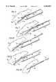
- FIGS. 6,7,8,9 and 10are views generally comparable to a portion of FIG. 3, showing steps in the sequence of placement of a catheter according to the method of the invention.
- FIGS. 11 and 12show comparative views of one embodiment of an articulated ultrasonic transducer in its normal and articulated conditions, illustrating a method for preventing removal of the probe from the sheath while articulated.
- FIGS. 1 and 3show perspective views of an ultrasonic probe 10 fitting within a lumen of a sheath 12, inserted through a surgical port 14 installed in a puncture made in the skin 16 of a patient, so as to juxtapose the transducer 18 of the probe 10 to an organ 20 or other structure to be examined.
- Surgical port 14is of the conventional type used for various minimally-invasive surgical procedures, and has a circular lumen.
- Sheath 12is circular in cross-section, so as to be sealed to the lumen of port 14; this allows compressed gas to be retained in the vicinity of the surgical site as needed.
- the surgical port 14 and probe 10are identical in both FIGS. 1 and 3. However, in FIG. 1, the probe is illustrated as used to image the placement of a biopsy gun 22 including a handle portion 24 and a generally cylindrical portion 26 inserted within sheath 12, while FIG. 3 illustrates the use of the probe in precise placement of a rigid, elongated needle 30 having been inserted through a separate puncture 32 in the skin 16.
- sheath 12may be used for practice of both processes or specialized sheaths may be provided for both purposes. For example, if it is preferred to sterilize and reuse the sheath, it will normally be made useful for both purposes, while a disposable version may be specialized. It is generally an object of the invention to employ the same design of sheath 12 and the same ultrasonic probe 10 in both uses of the system of the invention. Therefore, a description of one use of the sheath should be construed as relating equally to the other unless explicitly indicated to the contrary.
- the ultrasonic probe 10includes an elongated cylindrical portion 34, an articulated portion 36, shown curved, at the end of which transducer 18 is mounted, and a handle portion 38.
- the handle portion 38includes control apparatus exemplified by concentric knobs 40, 42 for controlling the articulation of the probe. Rotation of the transducer about its axis may also be provided, operated by rotatable ring 41.
- the detailed structure of the probe and the control arrangements thereofmay be as discussed in further detail in commonly assigned U.S. Pat. No. 5,413,102, incorporated by reference herein.
- the transducer 18is connected by signal wires 56 (FIG. 2) and a cable 44 to control and image processing electronics 46, which drive display 48 to provide an image of objects in the field of view 50 of the transducer 18.
- the elongated portion 26 of biopsy gun 22is passed through the same surgical port 14 and lumen of sheath 12 as is the ultrasonic probe 10.
- Other rigid elongated instrumentse.g., needles, needle holders, rigid catheters, and guide wires, can similarly be introduced while monitoring their positions.
- Reference herein to “biopsy guns”should be understood to refer to all such elongated instruments unless otherwise indicated, while reference herein and in the following claims to "rigid elongated instruments” should be understood to include biopsy guns as well as all other types of instruments introduced through the lumen of the sheath.
- Transducer 18images the field of view 50 and shows the tip 52 of the biopsy gun, e.g., penetrating the organ 20 to be examined.
- the gunis fired by operation of the handle portion 24, cutting a section of tissue free from the organ 20 and retracting it within the cylindrical portion 26 of the biopsy gun for withdrawal, pathologic examination and the like.
- the detailed structure and operation of biopsy gunsare well known, and are further discussed in the commonly-assigned Law '853 patent.
- FIG. 2shows a cross-section along line 2--2 of FIG. 1 and illustrates the sheath 12, within which fit the cylindrical portion 34 of the probe 10 and the cylindrical portion 26 of the biopsy gun 22.
- control wires 54for controlling the articulation of the probe
- signal wires 56for carrying drive and return signals to and from the transducer, shown in a strictly schematic fashion. Further details of representative signal processing electronics and control arrangements of the articulated ultrasonic probe are found in the commonly-assigned patents discussed above.
- the relative radial positions of the biopsy gun 22 and the probe 10may be maintained as illustrated in FIGS. 2 and 2A.
- the cylindrical portion 26 of the biopsy gunfits between pairs of inward protuberances or "dimples" 58 formed on either side of a line extending the length of sheath 12, confining cylindrical portion 26 to the space between the dimples 58 and the probe 34.
- the relative positions of the biopsy gun and probecould also be maintained by provision of separate lumens within sheath 12, as discussed in the Law '853 patent at col. 20, line 64.
- separate lumenswould be relatively difficult to sterilize, while the simple dimpled sheath is easily disinfected.
- the dimplesalso urge probe 34 away from the side of the sheath 12 in which the dimples 58 are formed.
- a keyhole-shaped slot 60is also formed in the sheath along the line extending between the pairs of dimples 58, for use of the sheath in placement of a needle, e.g., for placement of a catheter, as discussed in detail below in connection with FIG. 3. More specifically, if the sheath 12 is to be used only with the biopsy gun, keyhole slot 60 can be omitted; if the same sheath is to be useful for placement of either the biopsy gun or with a rigid needle for placement of a catheter, then the slot 60 is provided in the sheath as well.
- sheath 12may be used for both purposes, or specialized sheaths may be provided for each.
- sheathmay be reusable and thus sterilized, it may be formed of stainless steel tubing, e.g., 0.3 mm wall thickness; where the sheath is intended to be disposable, it can be molded of a biocompatable plastic material.
- the relative orientation of the probe 10, the sheath 12, and the biopsy gun 22is made positive by providing cooperating members at their distal ends. See FIG. 2A.
- the handle portion 24 of the biopsy gun 22 and the handle portion 38 of the probemeet at juxtaposed flat surfaces, essentially as discussed in the commonly-assigned Law '853 patent, and are provided with cooperating mounting structure 39.
- the cylindrical portion 34 of the probeis offset with respect to handle portion 38, so that the outer surface of cylindrical portion 34 is generally tangent to the flat surface 38a to which the handle portion 24 of the biopsy gun 22 is mounted. Accordingly, the cylindrical portions of probe 10 and gun 22 are closely juxtaposed and parallel to one another. Numerous other arrangements whereby the gun 22 and probe 60 may be reliably fixed with respect to one another will be apparent to those of skill in the art, and are within the scope of the invention.
- biopsy gun 22 and probe 10may conveniently be employed to carry cooperating coding means whereby various salient characteristics may be communicated from one to the other upon their assembly.
- certain conventional biopsy gunstake a tissue sample 15 mm from their tips when fired, while others may sample only 5 mm from their tips. If this characteristic of the gun is communicated to the image control circuitry 46 by encoding means when the gun is mounted to the probe, a target indicating the point at which the sample will be taken can be superimposed on the image of the organ visible to the surgeon on display 48, ensuring biopsy of the tissue of principal interest.
- the handle portion 24 of gun 22may be provided with a magnetic stripe and the handle portion 38 of probe 10 with a cooperating reader.
- Another possibilitywould be to provide a series of light-emitting diodes arranged in an encoded pattern on the gun, and a photo transistor on the probe to detect their presence, as illustrated schematically at 37.
- Other cooperative encoding arrangementsare within the skill of the art.
- the sheathmay similarly be keyed to the probe to insure that the biopsy gun 22, sheath 12, and probe 10 are all in fixed radial alignment to one another.
- the sheathis shown shaped to fit beneath the handle 24 of the biopsy gun, preventing relative rotation thereof.
- Snap-fitting detentsmay be provided to secure the components of the assembly together, e.g., when the probe and the biopsy gun have been inserted into the sheath.
- the sheathmay be formed with a cut-away portion indicated generally at 12a, which allows articulation of the probe 10 only in the direction away from the biopsy gun 22; that is, the side of the sheath along which the biopsy gun fits extends past the beginning of the articulable portion 36 of the probe, precluding the probe from bending upwardly and impacting the transducer 18 against the biopsy gun 26.
- the handle 24 of gun 22may include a tang 24a fitting into a slot 41a in ring 41, securing the transducer in a fixed radial position.
- ring 41can be formed to extend radially outwardly from the handle of the probe. A slot or hole can then be provided in the ring through which the needle must extend; this ensures that the transducer is properly aligned, that is, so that the needle is in the field of view of the transducer.
- FIG. 3shows, as mentioned, a view comparable to FIG. 1, but illustrating use of the ultrasonic probe 10 and sheath 12 to place precisely the tip of an elongated relatively rigid needle 30 inserted through a separate skin puncture 32.
- the needle 30fits within a wider first portion 62 of an elongated keyhole-shaped slot 60, but is too wide to pass through a second narrower portion 64 terminating at the distal end of the sheath 12.
- a surgeoninserts needle 30 through puncture 32, and then through the wider portion 62 of the slot 60, so that its tip emerges in the field of view 50 of the transducer 18, as shown.
- FIGS. 6 through 10illustrates the steps in the placement of a flexible catheter at the precise point in organ 20, followed by removal of the probe, sheath, and port.
- FIG. 4Further details shown in FIG. 4 include the inward protrusions or dimples 58, also shown in the end view of FIG. 5.
- the dimples 58locate the probe with respect to the sheath and space it from the keyhole-shaped slot 60, so that needle 30 does not impact transducer 18. Again, other means of spacing the probe from the needle 30 might be provided.
- the keyhole-shaped slot 60 shown in FIGS. 1-4, 5, and 6-10is essentially formed by removal of a portion of the sheath.
- an indentation 12ais formed in the tubular surface of the sheath 12', adjacent the proximal portion of the slot 60', to assist in guiding the tip of a needle into the slot.
- Slot 60'is relatively truncated as compared to the elongated slot shown in the other figures but again includes a wider portion to pass the relatively rigid needle 30 and a relatively narrow portion to pass the catheter 70.
- the indentationprovides a "target" for the tip of the needle.
- the indentation 12ameets the edge of the slot below the surface of the sheath, as the needle is urged forwardly along the indentation, the tip of the needle is guided into the slot, simplifying its insertion.
- the indentation 12aprecludes use of the sheath 12' with a biopsy probe.
- Other embodiments of the slotproviding essentially the same functions described, that is, guiding a relatively larger diameter rigid member into the vicinity of the transducer, and allowing the sheath to be removed while leaving a smaller-diameter, flexible catheter in place, are within the scope of the invention.
- a principal reason for location of the tip of needle 30 at a particular point in organ 20is as a step in placement of the tip of a flexible catheter or similar elongated flexible structure at the precise point desired.
- a cathetermay be thus placed to enable delivery of a drug to a precisely determined point within an organ 20 for various therapeutic purposes.
- the method of the inventioncan be used similarly to place components for repetitive blood sampling, or a sensor or stimulating electrodes connected by flexible wires to external circuitry.
- a relatively flexible catheter or like structure thus placed precisely according to the inventioncan be left in place for an extended time without undue discomfort.
- FIG. 6corresponds substantially to FIG. 3, and illustrates the sheath 12 in place, and the probe 10 and transducer 18 protruding therefrom so as to image the organ 20.
- a rigid needle 30is inserted through a separate skin puncture 32 spaced away from port 14 (FIG. 3) and through the wide portion 62 of the slot 60.
- the tip of needle 30then enters the field of view 50 of transducer 18, so that its position can be viewed on monitor 48 (FIG. 1) enabling its accurate placement.
- a second smaller membertypically a flexible catheter 70, or a guide wire, is passed down the lumen of the needle 30 as shown in FIG. 7.
- the catheter 70is of a diameter less than the width of the narrow portion 64 of the slot 60. This allows the sheath subsequently to be removed from the surgical port while leaving catheter 70 in place. Before this can be performed, however, needle 30 must be removed, as indicated in FIG. 8, leaving catheter 70 in place.
- catheter 70is inserted without a proximal terminal fitting, enabling the needle to be removed from its proximal end.
- a suitable terminal fitting(not shown) is then applied to catheter 70.
- the probe and sheathare removed, while the catheter 70 slides along the narrow portion 64 of the slot 60, in order to remain at the desired position in organ 20.
- the surgical port 14can then be removed and the incision closed.
- the catheter 70can then be used for supply of drugs to the precise position desired, for blood withdrawal or infusion, or for other various purposes. A series of several catheters could be placed similarly.
- a guide wiremay be slid down the lumen of the needle, in a step corresponding to that shown in FIG. 7, followed by removal of the needle, as shown in FIG. 8, and removal of the sheath 12 and probe 10, as shown in FIG. 9.
- a larger diameter catheter 74can then be placed over the guide wire 72, and the wire 72 removed, both as indicated in FIG. 10.
- the inventionallows a relatively flexible structure to be inserted through a small puncture and left in place, while the relatively large and cumbersome probe needed for precise placement, together with the surgical port, sheath, and rigid needle, can all be withdrawn and the larger puncture required for their introduction closed properly.
- sheath and probe combination according to the inventionwhether used with a biopsy gun or other rigid elongated instrument extending parallel to the probe in the sheath, or with a separate needle introduced through a separate puncture, should be useful with surgical ports already in common use.
- Such surgical portsare available in 5, 10, and 12 mm inside diameters. It is within the skill of the art to fabricate the other components of the combination according to the invention, in particular sheath 12, to fit within the preexisting surgical ports and form a substantially gas-tight seal therewith. However, it will also be appreciated by those of skill in the art that such surgical ports commonly have very sharp edges at their circular distal openings.
- FIGS. 11 and 12show straight and articulated versions of the same probe, illustrating one expedient useful in preventing such damage.
- FIG. 12These figures illustrate a probe 80 including a protective articulated section 86 which is constructed so as to assume a larger diameter when the probe is articulated, as illustrated in FIG. 12. Accordingly, if the surgeon attempts to withdraw the probe 82 from the portal 80 without straightening it out, the raised portion 88 will abut the end of the tubular surgical port 14, preventing damage to other portions of the probe. Obviously, the portion 86 may be made replaceable in the event of damage.
- Another expedient within the scope of the inventionis to make an outer sheath of the articulated portion of the probe of a first color and an inner material of contrasting color, such that any partial cuts or tears would be clearly visible, indicating that repair or replacement is required.
- Other expedientsare similarly within the skill of the art.
Landscapes
- Health & Medical Sciences (AREA)
- Life Sciences & Earth Sciences (AREA)
- Surgery (AREA)
- Nuclear Medicine, Radiotherapy & Molecular Imaging (AREA)
- Medical Informatics (AREA)
- Pathology (AREA)
- Veterinary Medicine (AREA)
- Engineering & Computer Science (AREA)
- Biomedical Technology (AREA)
- Heart & Thoracic Surgery (AREA)
- Public Health (AREA)
- Molecular Biology (AREA)
- General Health & Medical Sciences (AREA)
- Animal Behavior & Ethology (AREA)
- Biophysics (AREA)
- Physics & Mathematics (AREA)
- Radiology & Medical Imaging (AREA)
- Ultra Sonic Daignosis Equipment (AREA)
Abstract
Description
Claims (8)
Priority Applications (1)
| Application Number | Priority Date | Filing Date | Title |
|---|---|---|---|
| US09/253,745US6102867A (en) | 1997-02-11 | 1999-02-22 | Sheath and methods of ultrasonic guidance of biopsy and catheter insertion |
Applications Claiming Priority (2)
| Application Number | Priority Date | Filing Date | Title |
|---|---|---|---|
| US08/798,633US5931787A (en) | 1997-02-11 | 1997-02-11 | Sheath and methods of ultrasonic guidance for biopsy and catheter insertion |
| US09/253,745US6102867A (en) | 1997-02-11 | 1999-02-22 | Sheath and methods of ultrasonic guidance of biopsy and catheter insertion |
Related Parent Applications (2)
| Application Number | Title | Priority Date | Filing Date |
|---|---|---|---|
| US08/377,620DivisionUS5597479A (en) | 1995-01-25 | 1995-01-25 | Electro-coalescence/magnetic separation (ECMS) system and components for removal of contaminants from water streams, including desalinization |
| US08/798,633DivisionUS5931787A (en) | 1997-02-11 | 1997-02-11 | Sheath and methods of ultrasonic guidance for biopsy and catheter insertion |
Publications (1)
| Publication Number | Publication Date |
|---|---|
| US6102867Atrue US6102867A (en) | 2000-08-15 |
Family
ID=25173882
Family Applications (2)
| Application Number | Title | Priority Date | Filing Date |
|---|---|---|---|
| US08/798,633Expired - LifetimeUS5931787A (en) | 1997-02-11 | 1997-02-11 | Sheath and methods of ultrasonic guidance for biopsy and catheter insertion |
| US09/253,745Expired - LifetimeUS6102867A (en) | 1997-02-11 | 1999-02-22 | Sheath and methods of ultrasonic guidance of biopsy and catheter insertion |
Family Applications Before (1)
| Application Number | Title | Priority Date | Filing Date |
|---|---|---|---|
| US08/798,633Expired - LifetimeUS5931787A (en) | 1997-02-11 | 1997-02-11 | Sheath and methods of ultrasonic guidance for biopsy and catheter insertion |
Country Status (1)
| Country | Link |
|---|---|
| US (2) | US5931787A (en) |
Cited By (30)
| Publication number | Priority date | Publication date | Assignee | Title |
|---|---|---|---|---|
| US20010041838A1 (en)* | 1995-07-26 | 2001-11-15 | Holupka Edward J. | Virtual reality 3D visualization for surgical procedures |
| US6443902B1 (en)* | 1998-01-07 | 2002-09-03 | B-K Medical A/S | Ultrasound probe with a detachable needle guide, for collecting tissue samples |
| US6508783B2 (en) | 2001-03-14 | 2003-01-21 | Scimed Life Systems, Inc. | Ultrasound method for revascularization and drug delivery |
| US6554801B1 (en)* | 2000-10-26 | 2003-04-29 | Advanced Cardiovascular Systems, Inc. | Directional needle injection drug delivery device and method of use |
| US6591129B1 (en)* | 1996-02-15 | 2003-07-08 | Biosense, Inc. | Method for treating tissue through injection of a therapeutic agent |
| US20030135102A1 (en)* | 2000-05-18 | 2003-07-17 | Burdette Everette C. | Method and system for registration and guidance of intravascular treatment |
| US20030135115A1 (en)* | 1997-11-24 | 2003-07-17 | Burdette Everette C. | Method and apparatus for spatial registration and mapping of a biopsy needle during a tissue biopsy |
| US6758817B1 (en)* | 2002-09-11 | 2004-07-06 | Protek Medical Products, Inc. | Method and disposable apparatus for guiding needles |
| USD496728S1 (en) | 2003-05-16 | 2004-09-28 | Kimberly-Clark Worldwide, Inc. | Cannula having band markings |
| US20040260199A1 (en)* | 2003-06-19 | 2004-12-23 | Wilson-Cook Medical, Inc. | Cytology collection device |
| US6884219B1 (en)* | 2002-10-17 | 2005-04-26 | Rick L. Pruter | Method and disposable apparatus for guiding needles with an endocavity medical imaging device |
| US6908433B1 (en)* | 2002-05-10 | 2005-06-21 | Rick L. Pruter | Adhesive method and apparatus for guiding needles |
| US20050203413A1 (en)* | 2003-08-07 | 2005-09-15 | Gabor Fichtinger | Transcavital needle insertion device |
| US20050222518A1 (en)* | 2004-04-06 | 2005-10-06 | Genocell, Llc | Biopsy and injection catheters |
| US20060106315A1 (en)* | 2004-11-17 | 2006-05-18 | Roger Edens | Guided hypodermic cannula |
| US7187800B2 (en) | 2002-08-02 | 2007-03-06 | Computerized Medical Systems, Inc. | Method and apparatus for image segmentation using Jensen-Shannon divergence and Jensen-Renyi divergence |
| US7201715B2 (en) | 1997-11-24 | 2007-04-10 | Computerized Medical Systems, Inc. | Real time brachytherapy spatial registration and visualization system |
| US20070293787A1 (en)* | 2003-08-13 | 2007-12-20 | Taylor James D | Targeted biopsy delivery system |
| US20080009743A1 (en)* | 2006-06-15 | 2008-01-10 | Kazuyoshi Hayasaka | Ultrasound diagnosis apparatus, ultrasound probe and biopsy needle attachment |
| US20080086159A1 (en)* | 2006-06-21 | 2008-04-10 | Zweifler Michael D | Apparatus and method for reducing or eliminating the pain associated with an injection |
| US20080125709A1 (en)* | 2003-12-31 | 2008-05-29 | Gregory Waimong Chang | Needle catheter |
| US7438685B2 (en) | 2001-11-05 | 2008-10-21 | Computerized Medical Systems, Inc. | Apparatus and method for registration, guidance and targeting of external beam radiation therapy |
| US20090171219A1 (en)* | 2007-12-27 | 2009-07-02 | Masami Uchibori | Biopsy guide mounting structure, ultrasonic probe, and ultrasonic diagnostic apparatus |
| US7837627B1 (en) | 2002-05-10 | 2010-11-23 | Rick L Pruter | Sheath apparatus for guiding needles for use with a medical ultrasound transceiver |
| US8206304B1 (en)* | 2003-12-16 | 2012-06-26 | Vascular Technology Incorporated | Doppler transceiver and probe for use in minimally invasive procedures |
| USD669577S1 (en) | 2003-11-05 | 2012-10-23 | Kimberly-Clark Worldwide, Inc. | Cannula with band markings |
| WO2013155156A1 (en)* | 2012-04-10 | 2013-10-17 | The Johns Hopkins University | Cohesive robot-ultrasound probe for prostate biopsy |
| US8758256B2 (en) | 2010-07-12 | 2014-06-24 | Best Medical International, Inc. | Apparatus for brachytherapy that uses a scanning probe for treatment of malignant tissue |
| US9044216B2 (en) | 2010-07-12 | 2015-06-02 | Best Medical International, Inc. | Biopsy needle assembly |
| US11583249B2 (en) | 2017-09-08 | 2023-02-21 | Biosense Webster (Israel) Ltd. | Method and apparatus for performing non-fluoroscopic transseptal procedure |
Families Citing this family (29)
| Publication number | Priority date | Publication date | Assignee | Title |
|---|---|---|---|---|
| JPH11347037A (en)* | 1998-06-12 | 1999-12-21 | Asahi Optical Co Ltd | Ultrasound inspection device for insertion into body cavity |
| US6488689B1 (en)* | 1999-05-20 | 2002-12-03 | Aaron V. Kaplan | Methods and apparatus for transpericardial left atrial appendage closure |
| US6280432B1 (en)* | 1999-08-04 | 2001-08-28 | Embol-X, Inc. | Clip-on access port and methods of use |
| US7245959B1 (en)* | 2001-03-02 | 2007-07-17 | Scimed Life Systems, Inc. | Imaging catheter for use inside a guiding catheter |
| US7610104B2 (en)* | 2002-05-10 | 2009-10-27 | Cerebral Vascular Applications, Inc. | Methods and apparatus for lead placement on a surface of the heart |
| DK175024B1 (en)* | 2002-09-25 | 2004-05-03 | Bk Medical As | Catheter for introduction into the human body |
| JP3961472B2 (en)* | 2003-10-24 | 2007-08-22 | ジーイー・メディカル・システムズ・グローバル・テクノロジー・カンパニー・エルエルシー | Puncture guide and puncture ultrasound probe |
| WO2007119212A2 (en)* | 2006-04-13 | 2007-10-25 | Marcus Vincent Van Heerden | A surgical access device |
| US10595819B2 (en) | 2006-04-20 | 2020-03-24 | Gynesonics, Inc. | Ablation device with articulated imaging transducer |
| JP4936828B2 (en)* | 2006-09-07 | 2012-05-23 | 株式会社東芝 | Puncture adapter and ultrasonic probe |
| US7981041B2 (en)* | 2007-01-17 | 2011-07-19 | The Regents Of The University Of California | Sonographically guided transvaginal or transrectal pelvic abscess drainage using trocar method and biopsy guide attachment |
| US8088072B2 (en) | 2007-10-12 | 2012-01-03 | Gynesonics, Inc. | Methods and systems for controlled deployment of needles in tissue |
| US10368838B2 (en) | 2008-03-31 | 2019-08-06 | Intuitive Surgical Operations, Inc. | Surgical tools for laser marking and laser cutting |
| US7969866B2 (en)* | 2008-03-31 | 2011-06-28 | Telefonaktiebolaget L M Ericsson (Publ) | Hierarchical virtual private LAN service hub connectivity failure recovery |
| US9113816B2 (en)* | 2008-11-11 | 2015-08-25 | Eigen, Inc. | System and method for prostate biopsy |
| JP2013516288A (en)* | 2010-01-07 | 2013-05-13 | ベラソン インコーポレイテッド | Vascular access device, system and method |
| JP5265823B1 (en)* | 2011-10-27 | 2013-08-14 | オリンパスメディカルシステムズ株式会社 | Ultrasonic observation equipment |
| WO2015058096A1 (en) | 2013-10-18 | 2015-04-23 | Ziva Medical, Inc. | Methods and systems for the treatment of polycystic ovary syndrome |
| WO2016027502A1 (en)* | 2014-08-21 | 2016-02-25 | オリンパス株式会社 | Hard mirror set |
| US10238363B2 (en) | 2014-08-21 | 2019-03-26 | Richard D. Striano | Needle guide for ultrasound transducer |
| ES2964948T3 (en) | 2015-03-31 | 2024-04-10 | May Health Us Inc | Methods and systems for the manipulation of ovarian tissues |
| CN108882915A (en)* | 2016-01-27 | 2018-11-23 | 杰尼索尼克斯公司 | Disposible sheath for the ultrasonic probe being mounted on reusable needle construction |
| PL3515327T3 (en) | 2016-09-23 | 2024-06-10 | Atricure, Inc. | DEVICES FOR CLOSING THE LEFT ATRIAL APPEARANCE |
| CN115715689B (en) | 2016-11-11 | 2025-01-17 | 杰尼索尼克斯公司 | Tissue controlled treatment and dynamic interaction and comparison with tissue and/or treatment data |
| USD894384S1 (en)* | 2018-01-29 | 2020-08-25 | Transit Scientific, LLC | Elongated medical device with flexibility enhancing features |
| JP2021519143A (en) | 2018-03-27 | 2021-08-10 | センターハート・インコーポレイテッドSentreHEART, Inc. | Devices and methods for left atrial appendage closure |
| US11564736B2 (en) | 2019-01-25 | 2023-01-31 | May Health Sas | Systems and methods for applying energy to ovarian tissue |
| CN113520330A (en)* | 2021-08-23 | 2021-10-22 | 广州永士达医疗科技有限责任公司 | OCT detects nasopharynx guide and includes its biopsy device |
| US20230072174A1 (en)* | 2021-09-07 | 2023-03-09 | Daniel A. Crawford | Devices, systems, and methods for visualizing, accessing and performing interventions involving the thoracic duct |
Citations (12)
| Publication number | Priority date | Publication date | Assignee | Title |
|---|---|---|---|---|
| US4742829A (en)* | 1986-08-11 | 1988-05-10 | General Electric Company | Intracavitary ultrasound and biopsy probe for transvaginal imaging |
| US4759348A (en)* | 1981-09-28 | 1988-07-26 | Cawood Charles David | Endoscope assembly and surgical instrument for use therewith |
| US4877033A (en)* | 1988-05-04 | 1989-10-31 | Seitz Jr H Michael | Disposable needle guide and examination sheath for transvaginal ultrasound procedures |
| US4911173A (en)* | 1987-11-13 | 1990-03-27 | Diasonics, Inc. | Biopsy attachment for ultrasound probe |
| EP0446645A1 (en)* | 1990-02-20 | 1991-09-18 | Acoustic Imaging Technologies Corporation | Method and apparatus for ultrasonically probing a prostate |
| US5070879A (en)* | 1989-11-30 | 1991-12-10 | Acoustic Imaging Technologies Corp. | Ultrasound imaging method and apparatus |
| US5088500A (en)* | 1989-11-22 | 1992-02-18 | Victor J. Wedel | Ultrasound finger probe and method for use |
| US5090414A (en)* | 1988-08-22 | 1992-02-25 | Kabushiki Kaisha Toshiba | Intracavitary ultrasound probe |
| US5261409A (en)* | 1991-05-27 | 1993-11-16 | Sulzer Brothers Limited | Puncturing device for blood vessels |
| US5335663A (en)* | 1992-12-11 | 1994-08-09 | Tetrad Corporation | Laparoscopic probes and probe sheaths useful in ultrasonic imaging applications |
| US5443457A (en)* | 1994-02-24 | 1995-08-22 | Cardiovascular Imaging Systems, Incorporated | Tracking tip for a short lumen rapid exchange catheter |
| US5469853A (en)* | 1992-12-11 | 1995-11-28 | Tetrad Corporation | Bendable ultrasonic probe and sheath for use therewith |
Family Cites Families (2)
| Publication number | Priority date | Publication date | Assignee | Title |
|---|---|---|---|---|
| US4883059A (en)* | 1986-11-21 | 1989-11-28 | Advanced Technology Laboratories, Inc. | Intravaginal transducer biopsy guide |
| US4899756A (en)* | 1988-07-18 | 1990-02-13 | Sonek Jiri D | Articulated needle guide for ultrasound imaging and method of using same |
- 1997
- 1997-02-11USUS08/798,633patent/US5931787A/ennot_activeExpired - Lifetime
- 1999
- 1999-02-22USUS09/253,745patent/US6102867A/ennot_activeExpired - Lifetime
Patent Citations (12)
| Publication number | Priority date | Publication date | Assignee | Title |
|---|---|---|---|---|
| US4759348A (en)* | 1981-09-28 | 1988-07-26 | Cawood Charles David | Endoscope assembly and surgical instrument for use therewith |
| US4742829A (en)* | 1986-08-11 | 1988-05-10 | General Electric Company | Intracavitary ultrasound and biopsy probe for transvaginal imaging |
| US4911173A (en)* | 1987-11-13 | 1990-03-27 | Diasonics, Inc. | Biopsy attachment for ultrasound probe |
| US4877033A (en)* | 1988-05-04 | 1989-10-31 | Seitz Jr H Michael | Disposable needle guide and examination sheath for transvaginal ultrasound procedures |
| US5090414A (en)* | 1988-08-22 | 1992-02-25 | Kabushiki Kaisha Toshiba | Intracavitary ultrasound probe |
| US5088500A (en)* | 1989-11-22 | 1992-02-18 | Victor J. Wedel | Ultrasound finger probe and method for use |
| US5070879A (en)* | 1989-11-30 | 1991-12-10 | Acoustic Imaging Technologies Corp. | Ultrasound imaging method and apparatus |
| EP0446645A1 (en)* | 1990-02-20 | 1991-09-18 | Acoustic Imaging Technologies Corporation | Method and apparatus for ultrasonically probing a prostate |
| US5261409A (en)* | 1991-05-27 | 1993-11-16 | Sulzer Brothers Limited | Puncturing device for blood vessels |
| US5335663A (en)* | 1992-12-11 | 1994-08-09 | Tetrad Corporation | Laparoscopic probes and probe sheaths useful in ultrasonic imaging applications |
| US5469853A (en)* | 1992-12-11 | 1995-11-28 | Tetrad Corporation | Bendable ultrasonic probe and sheath for use therewith |
| US5443457A (en)* | 1994-02-24 | 1995-08-22 | Cardiovascular Imaging Systems, Incorporated | Tracking tip for a short lumen rapid exchange catheter |
Cited By (44)
| Publication number | Priority date | Publication date | Assignee | Title |
|---|---|---|---|---|
| US20010041838A1 (en)* | 1995-07-26 | 2001-11-15 | Holupka Edward J. | Virtual reality 3D visualization for surgical procedures |
| US7171255B2 (en) | 1995-07-26 | 2007-01-30 | Computerized Medical Systems, Inc. | Virtual reality 3D visualization for surgical procedures |
| US6591129B1 (en)* | 1996-02-15 | 2003-07-08 | Biosense, Inc. | Method for treating tissue through injection of a therapeutic agent |
| US7201715B2 (en) | 1997-11-24 | 2007-04-10 | Computerized Medical Systems, Inc. | Real time brachytherapy spatial registration and visualization system |
| US20030135115A1 (en)* | 1997-11-24 | 2003-07-17 | Burdette Everette C. | Method and apparatus for spatial registration and mapping of a biopsy needle during a tissue biopsy |
| US6443902B1 (en)* | 1998-01-07 | 2002-09-03 | B-K Medical A/S | Ultrasound probe with a detachable needle guide, for collecting tissue samples |
| US20030135102A1 (en)* | 2000-05-18 | 2003-07-17 | Burdette Everette C. | Method and system for registration and guidance of intravascular treatment |
| US20070135714A1 (en)* | 2000-10-26 | 2007-06-14 | Jeffrey Steward | Directional needle injection drug delivery device and method use |
| US6554801B1 (en)* | 2000-10-26 | 2003-04-29 | Advanced Cardiovascular Systems, Inc. | Directional needle injection drug delivery device and method of use |
| US20030233065A1 (en)* | 2000-10-26 | 2003-12-18 | Jeffrey Steward | Directional needle injection drug delivery device and method of use |
| US7179249B2 (en)* | 2000-10-26 | 2007-02-20 | Advanced Cardiovascular Systems, Inc. | Directional needle injection drug delivery device and method of use |
| WO2002074175A3 (en)* | 2001-03-14 | 2003-02-27 | Scimed Life Systems Inc | Ultrasound system and method for revascularization and drug delivery |
| US6702775B2 (en) | 2001-03-14 | 2004-03-09 | Scimed Life Systems, Inc. | Ultrasound method for revascularization and drug delivery |
| US6508783B2 (en) | 2001-03-14 | 2003-01-21 | Scimed Life Systems, Inc. | Ultrasound method for revascularization and drug delivery |
| US7438685B2 (en) | 2001-11-05 | 2008-10-21 | Computerized Medical Systems, Inc. | Apparatus and method for registration, guidance and targeting of external beam radiation therapy |
| US7837627B1 (en) | 2002-05-10 | 2010-11-23 | Rick L Pruter | Sheath apparatus for guiding needles for use with a medical ultrasound transceiver |
| US6908433B1 (en)* | 2002-05-10 | 2005-06-21 | Rick L. Pruter | Adhesive method and apparatus for guiding needles |
| US7187800B2 (en) | 2002-08-02 | 2007-03-06 | Computerized Medical Systems, Inc. | Method and apparatus for image segmentation using Jensen-Shannon divergence and Jensen-Renyi divergence |
| US8747324B1 (en) | 2002-09-11 | 2014-06-10 | Protek Medical Products, Inc. | Method and disposable apparatus for guiding needles |
| US6758817B1 (en)* | 2002-09-11 | 2004-07-06 | Protek Medical Products, Inc. | Method and disposable apparatus for guiding needles |
| US6884219B1 (en)* | 2002-10-17 | 2005-04-26 | Rick L. Pruter | Method and disposable apparatus for guiding needles with an endocavity medical imaging device |
| USD496728S1 (en) | 2003-05-16 | 2004-09-28 | Kimberly-Clark Worldwide, Inc. | Cannula having band markings |
| US20040260199A1 (en)* | 2003-06-19 | 2004-12-23 | Wilson-Cook Medical, Inc. | Cytology collection device |
| US20050203413A1 (en)* | 2003-08-07 | 2005-09-15 | Gabor Fichtinger | Transcavital needle insertion device |
| WO2005014079A3 (en)* | 2003-08-07 | 2008-10-09 | Univ Johns Hopkins | Transcavital needle insertion device |
| US20070293787A1 (en)* | 2003-08-13 | 2007-12-20 | Taylor James D | Targeted biopsy delivery system |
| US20090054807A1 (en)* | 2003-08-13 | 2009-02-26 | Taylor James D | Targeted biopsy delivery system |
| US7833168B2 (en) | 2003-08-13 | 2010-11-16 | Envisioneering Medical Technologies, Llc | Targeted biopsy delivery system |
| US20110144492A1 (en)* | 2003-08-13 | 2011-06-16 | Taylor James D | Targeted Treatment Delivery System |
| US8317724B2 (en) | 2003-08-13 | 2012-11-27 | Envisioneering, Llc | Targeted treatment delivery system |
| USD669577S1 (en) | 2003-11-05 | 2012-10-23 | Kimberly-Clark Worldwide, Inc. | Cannula with band markings |
| US8206304B1 (en)* | 2003-12-16 | 2012-06-26 | Vascular Technology Incorporated | Doppler transceiver and probe for use in minimally invasive procedures |
| US8152758B2 (en) | 2003-12-31 | 2012-04-10 | Advanced Cardiovascular Systems, Inc. | Needle catheter |
| US20080125709A1 (en)* | 2003-12-31 | 2008-05-29 | Gregory Waimong Chang | Needle catheter |
| US20050222518A1 (en)* | 2004-04-06 | 2005-10-06 | Genocell, Llc | Biopsy and injection catheters |
| US20060106315A1 (en)* | 2004-11-17 | 2006-05-18 | Roger Edens | Guided hypodermic cannula |
| US20080009743A1 (en)* | 2006-06-15 | 2008-01-10 | Kazuyoshi Hayasaka | Ultrasound diagnosis apparatus, ultrasound probe and biopsy needle attachment |
| US20080086159A1 (en)* | 2006-06-21 | 2008-04-10 | Zweifler Michael D | Apparatus and method for reducing or eliminating the pain associated with an injection |
| US20090171219A1 (en)* | 2007-12-27 | 2009-07-02 | Masami Uchibori | Biopsy guide mounting structure, ultrasonic probe, and ultrasonic diagnostic apparatus |
| US8758256B2 (en) | 2010-07-12 | 2014-06-24 | Best Medical International, Inc. | Apparatus for brachytherapy that uses a scanning probe for treatment of malignant tissue |
| US9044216B2 (en) | 2010-07-12 | 2015-06-02 | Best Medical International, Inc. | Biopsy needle assembly |
| WO2013155156A1 (en)* | 2012-04-10 | 2013-10-17 | The Johns Hopkins University | Cohesive robot-ultrasound probe for prostate biopsy |
| US10159469B2 (en) | 2012-04-10 | 2018-12-25 | The Johns Hopkins University | Cohesive robot-ultrasound probe for prostate biopsy |
| US11583249B2 (en) | 2017-09-08 | 2023-02-21 | Biosense Webster (Israel) Ltd. | Method and apparatus for performing non-fluoroscopic transseptal procedure |
Also Published As
| Publication number | Publication date |
|---|---|
| US5931787A (en) | 1999-08-03 |
Similar Documents
| Publication | Publication Date | Title |
|---|---|---|
| US6102867A (en) | Sheath and methods of ultrasonic guidance of biopsy and catheter insertion | |
| EP0883375B1 (en) | Precise position determination of endoscopes | |
| EP3685774B1 (en) | Medical device having visible puncture apparatus | |
| US20210045653A1 (en) | Graphical user interface for tissue biopsy system | |
| EP0910300B1 (en) | Site marking probe | |
| JP4581036B2 (en) | Ultrasound endoscope system, ultrasound probe, and ultrasound endoscope | |
| EP2091439B1 (en) | Devices for creating passages and sensing for blood vessels | |
| US6461296B1 (en) | Method and apparatus for delivery of genes, enzymes and biological agents to tissue cells | |
| EP2397097A1 (en) | Medical treatment device | |
| US20030073908A1 (en) | Method and apparatus for delivery of genes, enzymes and biological agents to tissue cells | |
| JP2001104315A (en) | Ultrasonic-guided paracentesis system device | |
| CN115363709A (en) | Bending-adjustable intravascular ultrasound-guided puncture method | |
| WO2021117649A1 (en) | Biopsy needle and tissue collection device | |
| JP2859826B2 (en) | Ultrasound probe with puncture needle guide | |
| WO1996022739A1 (en) | Medical probe device with scope and proximal aspiraton openings and method for treatment of the prostate with same | |
| JP2019166316A (en) | Catheter assemblies with offset device for tissue sampling, systems, and methods for sampling targeted region of tissue | |
| JPH07222747A (en) | Ultrasonic wave probe | |
| JPH10295631A (en) | Treatment appliance for endoscope |
Legal Events
| Date | Code | Title | Description |
|---|---|---|---|
| STCF | Information on status: patent grant | Free format text:PATENTED CASE | |
| REMI | Maintenance fee reminder mailed | ||
| FPAY | Fee payment | Year of fee payment:4 | |
| SULP | Surcharge for late payment | ||
| AS | Assignment | Owner name:GORE ENTERPRISE HOLDINGS, INC., DELAWARE Free format text:ASSIGNMENT OF ASSIGNORS INTEREST;ASSIGNOR:TETRAD CORPORATION;REEL/FRAME:017388/0684 Effective date:20051212 | |
| FPAY | Fee payment | Year of fee payment:8 | |
| REMI | Maintenance fee reminder mailed | ||
| AS | Assignment | Owner name:SOUND TECHNOLOGY, INC., PENNSYLVANIA Free format text:ASSIGNMENT OF ASSIGNORS INTEREST;ASSIGNOR:GORE ENTERPRISE HOLDINGS, INC.;REEL/FRAME:025713/0801 Effective date:20101221 | |
| FEPP | Fee payment procedure | Free format text:PAYOR NUMBER ASSIGNED (ORIGINAL EVENT CODE: ASPN); ENTITY STATUS OF PATENT OWNER: LARGE ENTITY | |
| FEPP | Fee payment procedure | Free format text:PETITION RELATED TO MAINTENANCE FEES FILED (ORIGINAL EVENT CODE: PMFP); ENTITY STATUS OF PATENT OWNER: LARGE ENTITY Free format text:PETITION RELATED TO MAINTENANCE FEES GRANTED (ORIGINAL EVENT CODE: PMFG); ENTITY STATUS OF PATENT OWNER: LARGE ENTITY | |
| AS | Assignment | Owner name:W. L. GORE & ASSOCIATES, INC., DELAWARE Free format text:ASSIGNMENT OF ASSIGNORS INTEREST;ASSIGNOR:GORE ENTERPRISE HOLDINGS, INC.;REEL/FRAME:027906/0508 Effective date:20120130 | |
| REMI | Maintenance fee reminder mailed | ||
| AS | Assignment | Owner name:W. L. GORE & ASSOCIATES, INC., DELAWARE Free format text:NULLIFICATION TO VOID PROPERTY NUMBERS RECORDED ON REEL 027906 FRAME 0508 THAT WERE NOT OWNED BY THE CONVEYING PARTY INDICATED ON THE RECORDATION COVER SHEET;ASSIGNOR:GORE ENTERPRISE HOLDINGS, INC.;REEL/FRAME:028278/0940 Effective date:20120130 | |
| PRDP | Patent reinstated due to the acceptance of a late maintenance fee | Effective date:20120906 | |
| FPAY | Fee payment | Year of fee payment:12 | |
| SULP | Surcharge for late payment |