US6102046A - Systems and methods for electrosurgical tissue revascularization - Google Patents
Systems and methods for electrosurgical tissue revascularizationDownload PDFInfo
- Publication number
- US6102046A US6102046AUS09/089,012US8901298AUS6102046AUS 6102046 AUS6102046 AUS 6102046AUS 8901298 AUS8901298 AUS 8901298AUS 6102046 AUS6102046 AUS 6102046A
- Authority
- US
- United States
- Prior art keywords
- tissue
- electrode
- meniscus
- electrode terminal
- probe
- Prior art date
- Legal status (The legal status is an assumption and is not a legal conclusion. Google has not performed a legal analysis and makes no representation as to the accuracy of the status listed.)
- Expired - Fee Related
Links
- 238000000034methodMethods0.000titleclaimsabstractdescription138
- 230000000250revascularizationEffects0.000titleclaimsabstractdescription19
- 230000005499meniscusEffects0.000claimsabstractdescription66
- 230000017531blood circulationEffects0.000claimsabstractdescription16
- 239000000523sampleSubstances0.000claimsdescription103
- 239000012530fluidSubstances0.000claimsdescription100
- FAPWRFPIFSIZLT-UHFFFAOYSA-MSodium chlorideChemical compound[Na+].[Cl-]FAPWRFPIFSIZLT-UHFFFAOYSA-M0.000claimsdescription18
- 210000003127kneeAnatomy0.000claimsdescription8
- 210000004369bloodAnatomy0.000abstractdescription36
- 239000008280bloodSubstances0.000abstractdescription36
- 230000008439repair processEffects0.000abstractdescription6
- 210000005166vasculatureAnatomy0.000abstractdescription4
- 238000004891communicationMethods0.000abstractdescription3
- 239000011800void materialSubstances0.000abstractdescription2
- 210000001519tissueAnatomy0.000description149
- 210000002216heartAnatomy0.000description71
- 238000002679ablationMethods0.000description27
- 210000005003heart tissueAnatomy0.000description19
- 210000004165myocardiumAnatomy0.000description19
- 230000023597hemostasisEffects0.000description17
- 239000010410layerSubstances0.000description17
- 102000008186CollagenHuman genes0.000description15
- 108010035532CollagenProteins0.000description15
- 238000005345coagulationMethods0.000description15
- 230000015271coagulationEffects0.000description15
- 229920001436collagenPolymers0.000description15
- 238000002604ultrasonographyMethods0.000description13
- 230000002861ventricularEffects0.000description13
- 230000006378damageEffects0.000description12
- 230000000694effectsEffects0.000description12
- 230000005684electric fieldEffects0.000description12
- 239000000463materialSubstances0.000description12
- 239000011159matrix materialSubstances0.000description12
- 238000010494dissociation reactionMethods0.000description11
- 230000005593dissociationsEffects0.000description11
- 239000007943implantSubstances0.000description11
- 239000000956alloySubstances0.000description10
- 239000011521glassSubstances0.000description10
- 238000010438heat treatmentMethods0.000description10
- 230000003902lesionEffects0.000description10
- 210000000988bone and boneAnatomy0.000description9
- 239000000919ceramicSubstances0.000description9
- 210000001174endocardiumAnatomy0.000description9
- 229910052751metalInorganic materials0.000description9
- 230000017074necrotic cell deathEffects0.000description9
- 229910045601alloyInorganic materials0.000description8
- 238000005520cutting processMethods0.000description8
- 230000035876healingEffects0.000description8
- 230000001965increasing effectEffects0.000description8
- 239000002184metalSubstances0.000description8
- 230000035515penetrationEffects0.000description8
- 230000008569processEffects0.000description8
- 210000004204blood vesselAnatomy0.000description7
- 210000004351coronary vesselAnatomy0.000description7
- 238000002847impedance measurementMethods0.000description7
- 238000007789sealingMethods0.000description7
- 210000000115thoracic cavityAnatomy0.000description7
- 238000013459approachMethods0.000description6
- 239000012634fragmentSubstances0.000description6
- 230000003601intercostal effectEffects0.000description6
- 230000002107myocardial effectEffects0.000description6
- 239000002245particleSubstances0.000description6
- BASFCYQUMIYNBI-UHFFFAOYSA-NplatinumChemical compound[Pt]BASFCYQUMIYNBI-UHFFFAOYSA-N0.000description6
- 229910001285shape-memory alloyInorganic materials0.000description6
- 238000001356surgical procedureMethods0.000description6
- CURLTUGMZLYLDI-UHFFFAOYSA-NCarbon dioxideChemical compoundO=C=OCURLTUGMZLYLDI-UHFFFAOYSA-N0.000description5
- 230000008901benefitEffects0.000description5
- 230000004907fluxEffects0.000description5
- 239000007789gasSubstances0.000description5
- 210000005036nerveAnatomy0.000description5
- 238000009834vaporizationMethods0.000description5
- 230000008016vaporizationEffects0.000description5
- 230000002159abnormal effectEffects0.000description4
- 230000015572biosynthetic processEffects0.000description4
- 230000036770blood supplyEffects0.000description4
- 229910002092carbon dioxideInorganic materials0.000description4
- 238000000576coating methodMethods0.000description4
- 239000004020conductorSubstances0.000description4
- 238000007796conventional methodMethods0.000description4
- 238000013461designMethods0.000description4
- 210000000629knee jointAnatomy0.000description4
- 210000005240left ventricleAnatomy0.000description4
- 238000004519manufacturing processMethods0.000description4
- 230000002093peripheral effectEffects0.000description4
- 239000011780sodium chlorideSubstances0.000description4
- 208000007536ThrombosisDiseases0.000description3
- RTAQQCXQSZGOHL-UHFFFAOYSA-NTitaniumChemical compound[Ti]RTAQQCXQSZGOHL-UHFFFAOYSA-N0.000description3
- QVGXLLKOCUKJST-UHFFFAOYSA-Natomic oxygenChemical compound[O]QVGXLLKOCUKJST-UHFFFAOYSA-N0.000description3
- 230000000740bleeding effectEffects0.000description3
- 210000000845cartilageAnatomy0.000description3
- 210000004027cellAnatomy0.000description3
- 238000010276constructionMethods0.000description3
- 230000008602contractionEffects0.000description3
- 208000029078coronary artery diseaseDiseases0.000description3
- 230000008878couplingEffects0.000description3
- 238000010168coupling processMethods0.000description3
- 238000005859coupling reactionMethods0.000description3
- 238000005516engineering processMethods0.000description3
- 238000003698laser cuttingMethods0.000description3
- 239000007788liquidSubstances0.000description3
- 230000007246mechanismEffects0.000description3
- 210000003928nasal cavityAnatomy0.000description3
- 239000001301oxygenSubstances0.000description3
- 229910052760oxygenInorganic materials0.000description3
- 229910052697platinumInorganic materials0.000description3
- 239000007787solidSubstances0.000description3
- 239000010935stainless steelSubstances0.000description3
- 230000003685thermal hair damageEffects0.000description3
- 210000002303tibiaAnatomy0.000description3
- 239000010936titaniumSubstances0.000description3
- 229910052719titaniumInorganic materials0.000description3
- 210000000689upper legAnatomy0.000description3
- XKRFYHLGVUSROY-UHFFFAOYSA-NArgonChemical compound[Ar]XKRFYHLGVUSROY-UHFFFAOYSA-N0.000description2
- IJGRMHOSHXDMSA-UHFFFAOYSA-NAtomic nitrogenChemical compoundN#NIJGRMHOSHXDMSA-UHFFFAOYSA-N0.000description2
- RYGMFSIKBFXOCR-UHFFFAOYSA-NCopperChemical compound[Cu]RYGMFSIKBFXOCR-UHFFFAOYSA-N0.000description2
- XEEYBQQBJWHFJM-UHFFFAOYSA-NIronChemical compound[Fe]XEEYBQQBJWHFJM-UHFFFAOYSA-N0.000description2
- 206010072970Meniscus injuryDiseases0.000description2
- PXHVJJICTQNCMI-UHFFFAOYSA-NNickelChemical compound[Ni]PXHVJJICTQNCMI-UHFFFAOYSA-N0.000description2
- 239000004642PolyimideSubstances0.000description2
- 208000027418Wounds and injuryDiseases0.000description2
- 238000003491arrayMethods0.000description2
- 230000000747cardiac effectEffects0.000description2
- 230000015556catabolic processEffects0.000description2
- 230000008859changeEffects0.000description2
- 239000011248coating agentSubstances0.000description2
- 229910052802copperInorganic materials0.000description2
- 239000010949copperSubstances0.000description2
- 210000003792cranial nerveAnatomy0.000description2
- 230000001186cumulative effectEffects0.000description2
- 230000003412degenerative effectEffects0.000description2
- 238000001514detection methodMethods0.000description2
- 230000003628erosive effectEffects0.000description2
- 210000000968fibrocartilageAnatomy0.000description2
- 239000003292glueSubstances0.000description2
- 239000001257hydrogenSubstances0.000description2
- 229910052739hydrogenInorganic materials0.000description2
- 230000001939inductive effectEffects0.000description2
- 230000002401inhibitory effectEffects0.000description2
- 229910010272inorganic materialInorganic materials0.000description2
- 239000011147inorganic materialSubstances0.000description2
- 238000003780insertionMethods0.000description2
- 230000037431insertionEffects0.000description2
- 238000009413insulationMethods0.000description2
- 229910000734martensiteInorganic materials0.000description2
- VNWKTOKETHGBQD-UHFFFAOYSA-NmethaneChemical compoundCVNWKTOKETHGBQD-UHFFFAOYSA-N0.000description2
- 238000002324minimally invasive surgeryMethods0.000description2
- 210000004417patellaAnatomy0.000description2
- 230000037361pathwayEffects0.000description2
- 231100000435percutaneous penetrationToxicity0.000description2
- 229920000728polyesterPolymers0.000description2
- 229920001721polyimidePolymers0.000description2
- 229920000642polymerPolymers0.000description2
- 229920001296polysiloxanePolymers0.000description2
- -1polytetrafluoroethylenePolymers0.000description2
- 229920001343polytetrafluoroethylenePolymers0.000description2
- 239000004810polytetrafluoroethyleneSubstances0.000description2
- 239000003566sealing materialSubstances0.000description2
- 229910001220stainless steelInorganic materials0.000description2
- 229910001256stainless steel alloyInorganic materials0.000description2
- 230000002966stenotic effectEffects0.000description2
- 239000002344surface layerSubstances0.000description2
- 210000004353tibial menisciAnatomy0.000description2
- 230000000451tissue damageEffects0.000description2
- 231100000827tissue damageToxicity0.000description2
- WFKWXMTUELFFGS-UHFFFAOYSA-NtungstenChemical compound[W]WFKWXMTUELFFGS-UHFFFAOYSA-N0.000description2
- 229910052721tungstenInorganic materials0.000description2
- 239000010937tungstenSubstances0.000description2
- 208000037260Atherosclerotic PlaqueDiseases0.000description1
- 241001631457CannulaSpecies0.000description1
- OKTJSMMVPCPJKN-UHFFFAOYSA-NCarbonChemical compound[C]OKTJSMMVPCPJKN-UHFFFAOYSA-N0.000description1
- VYZAMTAEIAYCRO-UHFFFAOYSA-NChromiumChemical compound[Cr]VYZAMTAEIAYCRO-UHFFFAOYSA-N0.000description1
- 239000004593EpoxySubstances0.000description1
- UFHFLCQGNIYNRP-UHFFFAOYSA-NHydrogenChemical compound[H][H]UFHFLCQGNIYNRP-UHFFFAOYSA-N0.000description1
- DGAQECJNVWCQMB-PUAWFVPOSA-MIlexoside XXIXChemical compoundC[C@@H]1CC[C@@]2(CC[C@@]3(C(=CC[C@H]4[C@]3(CC[C@@H]5[C@@]4(CC[C@@H](C5(C)C)OS(=O)(=O)[O-])C)C)[C@@H]2[C@]1(C)O)C)C(=O)O[C@H]6[C@@H]([C@H]([C@@H]([C@H](O6)CO)O)O)O.[Na+]DGAQECJNVWCQMB-PUAWFVPOSA-M0.000description1
- ZOKXTWBITQBERF-UHFFFAOYSA-NMolybdenumChemical compound[Mo]ZOKXTWBITQBERF-UHFFFAOYSA-N0.000description1
- 206010028980NeoplasmDiseases0.000description1
- 229910000990Ni alloyInorganic materials0.000description1
- 206010036940Prostatic adenomaDiseases0.000description1
- VYPSYNLAJGMNEJ-UHFFFAOYSA-NSilicium dioxideChemical compoundO=[Si]=OVYPSYNLAJGMNEJ-UHFFFAOYSA-N0.000description1
- 208000007097Urinary Bladder NeoplasmsDiseases0.000description1
- HZEWFHLRYVTOIW-UHFFFAOYSA-N[Ti].[Ni]Chemical compound[Ti].[Ni]HZEWFHLRYVTOIW-UHFFFAOYSA-N0.000description1
- 230000003213activating effectEffects0.000description1
- 239000000853adhesiveSubstances0.000description1
- 230000001070adhesive effectEffects0.000description1
- PNEYBMLMFCGWSK-UHFFFAOYSA-Naluminium oxideInorganic materials[O-2].[O-2].[O-2].[Al+3].[Al+3]PNEYBMLMFCGWSK-UHFFFAOYSA-N0.000description1
- 238000002399angioplastyMethods0.000description1
- 230000000702anti-platelet effectEffects0.000description1
- 239000003146anticoagulant agentSubstances0.000description1
- 229940127090anticoagulant agentDrugs0.000description1
- 229940127218antiplatelet drugDrugs0.000description1
- 210000000709aortaAnatomy0.000description1
- 229910052786argonInorganic materials0.000description1
- 210000001367arteryAnatomy0.000description1
- 125000004429atomChemical group0.000description1
- 230000006399behaviorEffects0.000description1
- 230000036760body temperatureEffects0.000description1
- 239000003990capacitorSubstances0.000description1
- 229910052799carbonInorganic materials0.000description1
- 239000001569carbon dioxideSubstances0.000description1
- 238000003763carbonizationMethods0.000description1
- 238000007675cardiac surgeryMethods0.000description1
- 230000004663cell proliferationEffects0.000description1
- 210000000038chestAnatomy0.000description1
- 229910052804chromiumInorganic materials0.000description1
- 239000011651chromiumSubstances0.000description1
- 230000004087circulationEffects0.000description1
- 229910017052cobaltInorganic materials0.000description1
- 239000010941cobaltSubstances0.000description1
- GUTLYIVDDKVIGB-UHFFFAOYSA-Ncobalt atomChemical compound[Co]GUTLYIVDDKVIGB-UHFFFAOYSA-N0.000description1
- 239000012141concentrateSubstances0.000description1
- 210000002808connective tissueAnatomy0.000description1
- 238000001816coolingMethods0.000description1
- 230000007797corrosionEffects0.000description1
- 238000005260corrosionMethods0.000description1
- 230000007423decreaseEffects0.000description1
- 229910003460diamondInorganic materials0.000description1
- 239000010432diamondSubstances0.000description1
- 201000010099diseaseDiseases0.000description1
- 208000037265diseases, disorders, signs and symptomsDiseases0.000description1
- 239000003814drugSubstances0.000description1
- 238000010292electrical insulationMethods0.000description1
- 238000002674endoscopic surgeryMethods0.000description1
- 238000012282endovascular techniqueMethods0.000description1
- 238000005530etchingMethods0.000description1
- 210000001105femoral arteryAnatomy0.000description1
- 239000000835fiberSubstances0.000description1
- 238000001914filtrationMethods0.000description1
- 230000006870functionEffects0.000description1
- 229930195733hydrocarbonNatural products0.000description1
- 150000002430hydrocarbonsChemical class0.000description1
- 125000004435hydrogen atomChemical class[H]*0.000description1
- 239000011810insulating materialSubstances0.000description1
- 239000012212insulatorSubstances0.000description1
- 229910052742ironInorganic materials0.000description1
- 230000001788irregularEffects0.000description1
- 230000000302ischemic effectEffects0.000description1
- WABPQHHGFIMREM-UHFFFAOYSA-Nlead(0)Chemical compound[Pb]WABPQHHGFIMREM-UHFFFAOYSA-N0.000description1
- 201000010260leiomyomaDiseases0.000description1
- 210000003041ligamentAnatomy0.000description1
- 210000004072lungAnatomy0.000description1
- 150000002739metalsChemical class0.000description1
- 230000004048modificationEffects0.000description1
- 238000012986modificationMethods0.000description1
- 239000011733molybdenumSubstances0.000description1
- 229910052750molybdenumInorganic materials0.000description1
- 210000003097mucusAnatomy0.000description1
- 210000004126nerve fiberAnatomy0.000description1
- 210000000944nerve tissueAnatomy0.000description1
- 229910052759nickelInorganic materials0.000description1
- 229910001000nickel titaniumInorganic materials0.000description1
- 229910052758niobiumInorganic materials0.000description1
- 239000010955niobiumSubstances0.000description1
- GUCVJGMIXFAOAE-UHFFFAOYSA-Nniobium atomChemical compound[Nb]GUCVJGMIXFAOAE-UHFFFAOYSA-N0.000description1
- 229910052757nitrogenInorganic materials0.000description1
- 229910017464nitrogen compoundInorganic materials0.000description1
- 150000002830nitrogen compoundsChemical class0.000description1
- 210000000196olfactory nerveAnatomy0.000description1
- 210000001328optic nerveAnatomy0.000description1
- 230000000399orthopedic effectEffects0.000description1
- 210000002741palatine tonsilAnatomy0.000description1
- 238000001259photo etchingMethods0.000description1
- 229920002120photoresistant polymerPolymers0.000description1
- 239000000106platelet aggregation inhibitorSubstances0.000description1
- 238000005086pumpingMethods0.000description1
- 230000005855radiationEffects0.000description1
- 230000009467reductionEffects0.000description1
- 239000012858resilient materialSubstances0.000description1
- 230000015541sensory perception of touchEffects0.000description1
- 238000007493shaping processMethods0.000description1
- 229910052710siliconInorganic materials0.000description1
- 239000010703siliconSubstances0.000description1
- 229910052708sodiumInorganic materials0.000description1
- 239000011734sodiumSubstances0.000description1
- 210000001584soft palateAnatomy0.000description1
- 125000006850spacer groupChemical group0.000description1
- 241000894007speciesSpecies0.000description1
- 210000001562sternumAnatomy0.000description1
- 238000000859sublimationMethods0.000description1
- 230000008022sublimationEffects0.000description1
- 230000002459sustained effectEffects0.000description1
- 208000024891symptomDiseases0.000description1
- 229910052715tantalumInorganic materials0.000description1
- GUVRBAGPIYLISA-UHFFFAOYSA-Ntantalum atomChemical compound[Ta]GUVRBAGPIYLISA-UHFFFAOYSA-N0.000description1
- 238000002207thermal evaporationMethods0.000description1
- 210000000779thoracic wallAnatomy0.000description1
- 230000009466transformationEffects0.000description1
- 210000002396uvulaAnatomy0.000description1
- 229910052720vanadiumInorganic materials0.000description1
- LEONUFNNVUYDNQ-UHFFFAOYSA-Nvanadium atomChemical compound[V]LEONUFNNVUYDNQ-UHFFFAOYSA-N0.000description1
- 230000002792vascularEffects0.000description1
- 210000003462veinAnatomy0.000description1
- 230000009278visceral effectEffects0.000description1
Images


Classifications
- A—HUMAN NECESSITIES
- A61—MEDICAL OR VETERINARY SCIENCE; HYGIENE
- A61B—DIAGNOSIS; SURGERY; IDENTIFICATION
- A61B18/00—Surgical instruments, devices or methods for transferring non-mechanical forms of energy to or from the body
- A61B18/04—Surgical instruments, devices or methods for transferring non-mechanical forms of energy to or from the body by heating
- A61B18/12—Surgical instruments, devices or methods for transferring non-mechanical forms of energy to or from the body by heating by passing a current through the tissue to be heated, e.g. high-frequency current
- A61B18/1206—Generators therefor
- A—HUMAN NECESSITIES
- A61—MEDICAL OR VETERINARY SCIENCE; HYGIENE
- A61B—DIAGNOSIS; SURGERY; IDENTIFICATION
- A61B18/00—Surgical instruments, devices or methods for transferring non-mechanical forms of energy to or from the body
- A61B18/04—Surgical instruments, devices or methods for transferring non-mechanical forms of energy to or from the body by heating
- A61B18/12—Surgical instruments, devices or methods for transferring non-mechanical forms of energy to or from the body by heating by passing a current through the tissue to be heated, e.g. high-frequency current
- A61B18/14—Probes or electrodes therefor
- A61B18/1402—Probes for open surgery
- A—HUMAN NECESSITIES
- A61—MEDICAL OR VETERINARY SCIENCE; HYGIENE
- A61B—DIAGNOSIS; SURGERY; IDENTIFICATION
- A61B18/00—Surgical instruments, devices or methods for transferring non-mechanical forms of energy to or from the body
- A61B18/04—Surgical instruments, devices or methods for transferring non-mechanical forms of energy to or from the body by heating
- A61B18/12—Surgical instruments, devices or methods for transferring non-mechanical forms of energy to or from the body by heating by passing a current through the tissue to be heated, e.g. high-frequency current
- A61B18/14—Probes or electrodes therefor
- A61B18/148—Probes or electrodes therefor having a short, rigid shaft for accessing the inner body transcutaneously, e.g. for neurosurgery or arthroscopy
- A—HUMAN NECESSITIES
- A61—MEDICAL OR VETERINARY SCIENCE; HYGIENE
- A61B—DIAGNOSIS; SURGERY; IDENTIFICATION
- A61B18/00—Surgical instruments, devices or methods for transferring non-mechanical forms of energy to or from the body
- A61B18/04—Surgical instruments, devices or methods for transferring non-mechanical forms of energy to or from the body by heating
- A61B18/12—Surgical instruments, devices or methods for transferring non-mechanical forms of energy to or from the body by heating by passing a current through the tissue to be heated, e.g. high-frequency current
- A61B18/14—Probes or electrodes therefor
- A61B18/1482—Probes or electrodes therefor having a long rigid shaft for accessing the inner body transcutaneously in minimal invasive surgery, e.g. laparoscopy
- A—HUMAN NECESSITIES
- A61—MEDICAL OR VETERINARY SCIENCE; HYGIENE
- A61B—DIAGNOSIS; SURGERY; IDENTIFICATION
- A61B18/00—Surgical instruments, devices or methods for transferring non-mechanical forms of energy to or from the body
- A61B18/04—Surgical instruments, devices or methods for transferring non-mechanical forms of energy to or from the body by heating
- A61B18/12—Surgical instruments, devices or methods for transferring non-mechanical forms of energy to or from the body by heating by passing a current through the tissue to be heated, e.g. high-frequency current
- A61B18/14—Probes or electrodes therefor
- A61B18/1485—Probes or electrodes therefor having a short rigid shaft for accessing the inner body through natural openings
- A—HUMAN NECESSITIES
- A61—MEDICAL OR VETERINARY SCIENCE; HYGIENE
- A61B—DIAGNOSIS; SURGERY; IDENTIFICATION
- A61B18/00—Surgical instruments, devices or methods for transferring non-mechanical forms of energy to or from the body
- A61B18/04—Surgical instruments, devices or methods for transferring non-mechanical forms of energy to or from the body by heating
- A61B18/12—Surgical instruments, devices or methods for transferring non-mechanical forms of energy to or from the body by heating by passing a current through the tissue to be heated, e.g. high-frequency current
- A61B18/14—Probes or electrodes therefor
- A61B18/149—Probes or electrodes therefor bow shaped or with rotatable body at cantilever end, e.g. for resectoscopes, or coagulating rollers
- A—HUMAN NECESSITIES
- A61—MEDICAL OR VETERINARY SCIENCE; HYGIENE
- A61B—DIAGNOSIS; SURGERY; IDENTIFICATION
- A61B18/00—Surgical instruments, devices or methods for transferring non-mechanical forms of energy to or from the body
- A61B18/04—Surgical instruments, devices or methods for transferring non-mechanical forms of energy to or from the body by heating
- A61B18/12—Surgical instruments, devices or methods for transferring non-mechanical forms of energy to or from the body by heating by passing a current through the tissue to be heated, e.g. high-frequency current
- A61B18/14—Probes or electrodes therefor
- A61B18/1492—Probes or electrodes therefor having a flexible, catheter-like structure, e.g. for heart ablation
- A—HUMAN NECESSITIES
- A61—MEDICAL OR VETERINARY SCIENCE; HYGIENE
- A61M—DEVICES FOR INTRODUCING MEDIA INTO, OR ONTO, THE BODY; DEVICES FOR TRANSDUCING BODY MEDIA OR FOR TAKING MEDIA FROM THE BODY; DEVICES FOR PRODUCING OR ENDING SLEEP OR STUPOR
- A61M25/00—Catheters; Hollow probes
- A61M25/01—Introducing, guiding, advancing, emplacing or holding catheters
- A61M25/0105—Steering means as part of the catheter or advancing means; Markers for positioning
- A61M25/0133—Tip steering devices
- A—HUMAN NECESSITIES
- A61—MEDICAL OR VETERINARY SCIENCE; HYGIENE
- A61B—DIAGNOSIS; SURGERY; IDENTIFICATION
- A61B17/00—Surgical instruments, devices or methods
- A61B2017/00017—Electrical control of surgical instruments
- A61B2017/00022—Sensing or detecting at the treatment site
- A61B2017/00026—Conductivity or impedance, e.g. of tissue
- A—HUMAN NECESSITIES
- A61—MEDICAL OR VETERINARY SCIENCE; HYGIENE
- A61B—DIAGNOSIS; SURGERY; IDENTIFICATION
- A61B17/00—Surgical instruments, devices or methods
- A61B2017/00017—Electrical control of surgical instruments
- A61B2017/00022—Sensing or detecting at the treatment site
- A61B2017/00084—Temperature
- A61B2017/00092—Temperature using thermocouples
- A61B2017/00097—Temperature using thermocouples one of the thermometric elements being an electrode or the heating element
- A—HUMAN NECESSITIES
- A61—MEDICAL OR VETERINARY SCIENCE; HYGIENE
- A61B—DIAGNOSIS; SURGERY; IDENTIFICATION
- A61B17/00—Surgical instruments, devices or methods
- A61B2017/00017—Electrical control of surgical instruments
- A61B2017/00022—Sensing or detecting at the treatment site
- A61B2017/00084—Temperature
- A61B2017/00101—Temperature using an array of thermosensors
- A—HUMAN NECESSITIES
- A61—MEDICAL OR VETERINARY SCIENCE; HYGIENE
- A61B—DIAGNOSIS; SURGERY; IDENTIFICATION
- A61B17/00—Surgical instruments, devices or methods
- A61B2017/00017—Electrical control of surgical instruments
- A61B2017/00022—Sensing or detecting at the treatment site
- A61B2017/00106—Sensing or detecting at the treatment site ultrasonic
- A—HUMAN NECESSITIES
- A61—MEDICAL OR VETERINARY SCIENCE; HYGIENE
- A61B—DIAGNOSIS; SURGERY; IDENTIFICATION
- A61B17/00—Surgical instruments, devices or methods
- A61B17/00234—Surgical instruments, devices or methods for minimally invasive surgery
- A61B2017/00238—Type of minimally invasive operation
- A61B2017/00243—Type of minimally invasive operation cardiac
- A61B2017/00247—Making holes in the wall of the heart, e.g. laser Myocardial revascularization
- A—HUMAN NECESSITIES
- A61—MEDICAL OR VETERINARY SCIENCE; HYGIENE
- A61B—DIAGNOSIS; SURGERY; IDENTIFICATION
- A61B17/00—Surgical instruments, devices or methods
- A61B17/00234—Surgical instruments, devices or methods for minimally invasive surgery
- A61B2017/00292—Surgical instruments, devices or methods for minimally invasive surgery mounted on or guided by flexible, e.g. catheter-like, means
- A61B2017/003—Steerable
- A—HUMAN NECESSITIES
- A61—MEDICAL OR VETERINARY SCIENCE; HYGIENE
- A61B—DIAGNOSIS; SURGERY; IDENTIFICATION
- A61B17/00—Surgical instruments, devices or methods
- A61B17/22—Implements for squeezing-off ulcers or the like on inner organs of the body; Implements for scraping-out cavities of body organs, e.g. bones; for invasive removal or destruction of calculus using mechanical vibrations; for removing obstructions in blood vessels, not otherwise provided for
- A61B2017/22001—Angioplasty, e.g. PCTA
- A—HUMAN NECESSITIES
- A61—MEDICAL OR VETERINARY SCIENCE; HYGIENE
- A61B—DIAGNOSIS; SURGERY; IDENTIFICATION
- A61B17/00—Surgical instruments, devices or methods
- A61B17/22—Implements for squeezing-off ulcers or the like on inner organs of the body; Implements for scraping-out cavities of body organs, e.g. bones; for invasive removal or destruction of calculus using mechanical vibrations; for removing obstructions in blood vessels, not otherwise provided for
- A61B2017/22038—Implements for squeezing-off ulcers or the like on inner organs of the body; Implements for scraping-out cavities of body organs, e.g. bones; for invasive removal or destruction of calculus using mechanical vibrations; for removing obstructions in blood vessels, not otherwise provided for with a guide wire
- A—HUMAN NECESSITIES
- A61—MEDICAL OR VETERINARY SCIENCE; HYGIENE
- A61B—DIAGNOSIS; SURGERY; IDENTIFICATION
- A61B18/00—Surgical instruments, devices or methods for transferring non-mechanical forms of energy to or from the body
- A61B2018/00005—Cooling or heating of the probe or tissue immediately surrounding the probe
- A61B2018/00011—Cooling or heating of the probe or tissue immediately surrounding the probe with fluids
- A61B2018/00029—Cooling or heating of the probe or tissue immediately surrounding the probe with fluids open
- A—HUMAN NECESSITIES
- A61—MEDICAL OR VETERINARY SCIENCE; HYGIENE
- A61B—DIAGNOSIS; SURGERY; IDENTIFICATION
- A61B18/00—Surgical instruments, devices or methods for transferring non-mechanical forms of energy to or from the body
- A61B2018/00053—Mechanical features of the instrument of device
- A61B2018/00059—Material properties
- A61B2018/00071—Electrical conductivity
- A61B2018/00083—Electrical conductivity low, i.e. electrically insulating
- A—HUMAN NECESSITIES
- A61—MEDICAL OR VETERINARY SCIENCE; HYGIENE
- A61B—DIAGNOSIS; SURGERY; IDENTIFICATION
- A61B18/00—Surgical instruments, devices or methods for transferring non-mechanical forms of energy to or from the body
- A61B2018/00053—Mechanical features of the instrument of device
- A61B2018/00107—Coatings on the energy applicator
- A61B2018/00119—Coatings on the energy applicator with metal oxide nitride
- A—HUMAN NECESSITIES
- A61—MEDICAL OR VETERINARY SCIENCE; HYGIENE
- A61B—DIAGNOSIS; SURGERY; IDENTIFICATION
- A61B18/00—Surgical instruments, devices or methods for transferring non-mechanical forms of energy to or from the body
- A61B2018/00053—Mechanical features of the instrument of device
- A61B2018/0016—Energy applicators arranged in a two- or three dimensional array
- A—HUMAN NECESSITIES
- A61—MEDICAL OR VETERINARY SCIENCE; HYGIENE
- A61B—DIAGNOSIS; SURGERY; IDENTIFICATION
- A61B18/00—Surgical instruments, devices or methods for transferring non-mechanical forms of energy to or from the body
- A61B2018/00053—Mechanical features of the instrument of device
- A61B2018/00172—Connectors and adapters therefor
- A61B2018/00178—Electrical connectors
- A—HUMAN NECESSITIES
- A61—MEDICAL OR VETERINARY SCIENCE; HYGIENE
- A61B—DIAGNOSIS; SURGERY; IDENTIFICATION
- A61B18/00—Surgical instruments, devices or methods for transferring non-mechanical forms of energy to or from the body
- A61B2018/00053—Mechanical features of the instrument of device
- A61B2018/00184—Moving parts
- A61B2018/00196—Moving parts reciprocating lengthwise
- A—HUMAN NECESSITIES
- A61—MEDICAL OR VETERINARY SCIENCE; HYGIENE
- A61B—DIAGNOSIS; SURGERY; IDENTIFICATION
- A61B18/00—Surgical instruments, devices or methods for transferring non-mechanical forms of energy to or from the body
- A61B2018/00315—Surgical instruments, devices or methods for transferring non-mechanical forms of energy to or from the body for treatment of particular body parts
- A61B2018/00321—Head or parts thereof
- A61B2018/00327—Ear, nose or throat
- A—HUMAN NECESSITIES
- A61—MEDICAL OR VETERINARY SCIENCE; HYGIENE
- A61B—DIAGNOSIS; SURGERY; IDENTIFICATION
- A61B18/00—Surgical instruments, devices or methods for transferring non-mechanical forms of energy to or from the body
- A61B2018/00315—Surgical instruments, devices or methods for transferring non-mechanical forms of energy to or from the body for treatment of particular body parts
- A61B2018/00345—Vascular system
- A61B2018/00351—Heart
- A61B2018/00392—Transmyocardial revascularisation
- A—HUMAN NECESSITIES
- A61—MEDICAL OR VETERINARY SCIENCE; HYGIENE
- A61B—DIAGNOSIS; SURGERY; IDENTIFICATION
- A61B18/00—Surgical instruments, devices or methods for transferring non-mechanical forms of energy to or from the body
- A61B2018/00315—Surgical instruments, devices or methods for transferring non-mechanical forms of energy to or from the body for treatment of particular body parts
- A61B2018/00452—Skin
- A61B2018/0047—Upper parts of the skin, e.g. skin peeling or treatment of wrinkles
- A—HUMAN NECESSITIES
- A61—MEDICAL OR VETERINARY SCIENCE; HYGIENE
- A61B—DIAGNOSIS; SURGERY; IDENTIFICATION
- A61B18/00—Surgical instruments, devices or methods for transferring non-mechanical forms of energy to or from the body
- A61B2018/00315—Surgical instruments, devices or methods for transferring non-mechanical forms of energy to or from the body for treatment of particular body parts
- A61B2018/00452—Skin
- A61B2018/00476—Hair follicles
- A—HUMAN NECESSITIES
- A61—MEDICAL OR VETERINARY SCIENCE; HYGIENE
- A61B—DIAGNOSIS; SURGERY; IDENTIFICATION
- A61B18/00—Surgical instruments, devices or methods for transferring non-mechanical forms of energy to or from the body
- A61B2018/00315—Surgical instruments, devices or methods for transferring non-mechanical forms of energy to or from the body for treatment of particular body parts
- A61B2018/00505—Urinary tract
- A—HUMAN NECESSITIES
- A61—MEDICAL OR VETERINARY SCIENCE; HYGIENE
- A61B—DIAGNOSIS; SURGERY; IDENTIFICATION
- A61B18/00—Surgical instruments, devices or methods for transferring non-mechanical forms of energy to or from the body
- A61B2018/00571—Surgical instruments, devices or methods for transferring non-mechanical forms of energy to or from the body for achieving a particular surgical effect
- A61B2018/00577—Ablation
- A61B2018/00583—Coblation, i.e. ablation using a cold plasma
- A—HUMAN NECESSITIES
- A61—MEDICAL OR VETERINARY SCIENCE; HYGIENE
- A61B—DIAGNOSIS; SURGERY; IDENTIFICATION
- A61B18/00—Surgical instruments, devices or methods for transferring non-mechanical forms of energy to or from the body
- A61B2018/00571—Surgical instruments, devices or methods for transferring non-mechanical forms of energy to or from the body for achieving a particular surgical effect
- A61B2018/00601—Cutting
- A—HUMAN NECESSITIES
- A61—MEDICAL OR VETERINARY SCIENCE; HYGIENE
- A61B—DIAGNOSIS; SURGERY; IDENTIFICATION
- A61B18/00—Surgical instruments, devices or methods for transferring non-mechanical forms of energy to or from the body
- A61B2018/00636—Sensing and controlling the application of energy
- A61B2018/00642—Sensing and controlling the application of energy with feedback, i.e. closed loop control
- A—HUMAN NECESSITIES
- A61—MEDICAL OR VETERINARY SCIENCE; HYGIENE
- A61B—DIAGNOSIS; SURGERY; IDENTIFICATION
- A61B18/00—Surgical instruments, devices or methods for transferring non-mechanical forms of energy to or from the body
- A61B2018/00636—Sensing and controlling the application of energy
- A61B2018/0066—Sensing and controlling the application of energy without feedback, i.e. open loop control
- A—HUMAN NECESSITIES
- A61—MEDICAL OR VETERINARY SCIENCE; HYGIENE
- A61B—DIAGNOSIS; SURGERY; IDENTIFICATION
- A61B18/00—Surgical instruments, devices or methods for transferring non-mechanical forms of energy to or from the body
- A61B2018/00636—Sensing and controlling the application of energy
- A61B2018/00666—Sensing and controlling the application of energy using a threshold value
- A61B2018/00678—Sensing and controlling the application of energy using a threshold value upper
- A—HUMAN NECESSITIES
- A61—MEDICAL OR VETERINARY SCIENCE; HYGIENE
- A61B—DIAGNOSIS; SURGERY; IDENTIFICATION
- A61B18/00—Surgical instruments, devices or methods for transferring non-mechanical forms of energy to or from the body
- A61B2018/00636—Sensing and controlling the application of energy
- A61B2018/00696—Controlled or regulated parameters
- A61B2018/00702—Power or energy
- A—HUMAN NECESSITIES
- A61—MEDICAL OR VETERINARY SCIENCE; HYGIENE
- A61B—DIAGNOSIS; SURGERY; IDENTIFICATION
- A61B18/00—Surgical instruments, devices or methods for transferring non-mechanical forms of energy to or from the body
- A61B2018/00636—Sensing and controlling the application of energy
- A61B2018/00696—Controlled or regulated parameters
- A61B2018/00726—Duty cycle
- A—HUMAN NECESSITIES
- A61—MEDICAL OR VETERINARY SCIENCE; HYGIENE
- A61B—DIAGNOSIS; SURGERY; IDENTIFICATION
- A61B18/00—Surgical instruments, devices or methods for transferring non-mechanical forms of energy to or from the body
- A61B2018/00636—Sensing and controlling the application of energy
- A61B2018/00696—Controlled or regulated parameters
- A61B2018/00738—Depth, e.g. depth of ablation
- A—HUMAN NECESSITIES
- A61—MEDICAL OR VETERINARY SCIENCE; HYGIENE
- A61B—DIAGNOSIS; SURGERY; IDENTIFICATION
- A61B18/00—Surgical instruments, devices or methods for transferring non-mechanical forms of energy to or from the body
- A61B2018/00636—Sensing and controlling the application of energy
- A61B2018/00696—Controlled or regulated parameters
- A61B2018/00755—Resistance or impedance
- A—HUMAN NECESSITIES
- A61—MEDICAL OR VETERINARY SCIENCE; HYGIENE
- A61B—DIAGNOSIS; SURGERY; IDENTIFICATION
- A61B18/00—Surgical instruments, devices or methods for transferring non-mechanical forms of energy to or from the body
- A61B2018/00636—Sensing and controlling the application of energy
- A61B2018/00696—Controlled or regulated parameters
- A61B2018/00761—Duration
- A—HUMAN NECESSITIES
- A61—MEDICAL OR VETERINARY SCIENCE; HYGIENE
- A61B—DIAGNOSIS; SURGERY; IDENTIFICATION
- A61B18/00—Surgical instruments, devices or methods for transferring non-mechanical forms of energy to or from the body
- A61B2018/00636—Sensing and controlling the application of energy
- A61B2018/00773—Sensed parameters
- A61B2018/00791—Temperature
- A61B2018/00797—Temperature measured by multiple temperature sensors
- A—HUMAN NECESSITIES
- A61—MEDICAL OR VETERINARY SCIENCE; HYGIENE
- A61B—DIAGNOSIS; SURGERY; IDENTIFICATION
- A61B18/00—Surgical instruments, devices or methods for transferring non-mechanical forms of energy to or from the body
- A61B2018/00636—Sensing and controlling the application of energy
- A61B2018/00773—Sensed parameters
- A61B2018/00791—Temperature
- A61B2018/00821—Temperature measured by a thermocouple
- A—HUMAN NECESSITIES
- A61—MEDICAL OR VETERINARY SCIENCE; HYGIENE
- A61B—DIAGNOSIS; SURGERY; IDENTIFICATION
- A61B18/00—Surgical instruments, devices or methods for transferring non-mechanical forms of energy to or from the body
- A61B2018/00636—Sensing and controlling the application of energy
- A61B2018/00773—Sensed parameters
- A61B2018/00827—Current
- A—HUMAN NECESSITIES
- A61—MEDICAL OR VETERINARY SCIENCE; HYGIENE
- A61B—DIAGNOSIS; SURGERY; IDENTIFICATION
- A61B18/00—Surgical instruments, devices or methods for transferring non-mechanical forms of energy to or from the body
- A61B2018/00636—Sensing and controlling the application of energy
- A61B2018/00773—Sensed parameters
- A61B2018/00875—Resistance or impedance
- A—HUMAN NECESSITIES
- A61—MEDICAL OR VETERINARY SCIENCE; HYGIENE
- A61B—DIAGNOSIS; SURGERY; IDENTIFICATION
- A61B18/00—Surgical instruments, devices or methods for transferring non-mechanical forms of energy to or from the body
- A61B2018/00636—Sensing and controlling the application of energy
- A61B2018/00773—Sensed parameters
- A61B2018/00886—Duration
- A—HUMAN NECESSITIES
- A61—MEDICAL OR VETERINARY SCIENCE; HYGIENE
- A61B—DIAGNOSIS; SURGERY; IDENTIFICATION
- A61B18/00—Surgical instruments, devices or methods for transferring non-mechanical forms of energy to or from the body
- A61B2018/00982—Surgical instruments, devices or methods for transferring non-mechanical forms of energy to or from the body combined with or comprising means for visual or photographic inspections inside the body, e.g. endoscopes
- A—HUMAN NECESSITIES
- A61—MEDICAL OR VETERINARY SCIENCE; HYGIENE
- A61B—DIAGNOSIS; SURGERY; IDENTIFICATION
- A61B18/00—Surgical instruments, devices or methods for transferring non-mechanical forms of energy to or from the body
- A61B18/04—Surgical instruments, devices or methods for transferring non-mechanical forms of energy to or from the body by heating
- A61B18/12—Surgical instruments, devices or methods for transferring non-mechanical forms of energy to or from the body by heating by passing a current through the tissue to be heated, e.g. high-frequency current
- A61B18/1206—Generators therefor
- A61B2018/1213—Generators therefor creating an arc
- A—HUMAN NECESSITIES
- A61—MEDICAL OR VETERINARY SCIENCE; HYGIENE
- A61B—DIAGNOSIS; SURGERY; IDENTIFICATION
- A61B18/00—Surgical instruments, devices or methods for transferring non-mechanical forms of energy to or from the body
- A61B18/04—Surgical instruments, devices or methods for transferring non-mechanical forms of energy to or from the body by heating
- A61B18/12—Surgical instruments, devices or methods for transferring non-mechanical forms of energy to or from the body by heating by passing a current through the tissue to be heated, e.g. high-frequency current
- A61B18/1206—Generators therefor
- A61B2018/124—Generators therefor switching the output to different electrodes, e.g. sequentially
- A—HUMAN NECESSITIES
- A61—MEDICAL OR VETERINARY SCIENCE; HYGIENE
- A61B—DIAGNOSIS; SURGERY; IDENTIFICATION
- A61B18/00—Surgical instruments, devices or methods for transferring non-mechanical forms of energy to or from the body
- A61B18/04—Surgical instruments, devices or methods for transferring non-mechanical forms of energy to or from the body by heating
- A61B18/12—Surgical instruments, devices or methods for transferring non-mechanical forms of energy to or from the body by heating by passing a current through the tissue to be heated, e.g. high-frequency current
- A61B18/1206—Generators therefor
- A61B2018/1246—Generators therefor characterised by the output polarity
- A61B2018/1253—Generators therefor characterised by the output polarity monopolar
- A—HUMAN NECESSITIES
- A61—MEDICAL OR VETERINARY SCIENCE; HYGIENE
- A61B—DIAGNOSIS; SURGERY; IDENTIFICATION
- A61B18/00—Surgical instruments, devices or methods for transferring non-mechanical forms of energy to or from the body
- A61B18/04—Surgical instruments, devices or methods for transferring non-mechanical forms of energy to or from the body by heating
- A61B18/12—Surgical instruments, devices or methods for transferring non-mechanical forms of energy to or from the body by heating by passing a current through the tissue to be heated, e.g. high-frequency current
- A61B18/1206—Generators therefor
- A61B2018/1246—Generators therefor characterised by the output polarity
- A61B2018/126—Generators therefor characterised by the output polarity bipolar
- A—HUMAN NECESSITIES
- A61—MEDICAL OR VETERINARY SCIENCE; HYGIENE
- A61B—DIAGNOSIS; SURGERY; IDENTIFICATION
- A61B18/00—Surgical instruments, devices or methods for transferring non-mechanical forms of energy to or from the body
- A61B18/04—Surgical instruments, devices or methods for transferring non-mechanical forms of energy to or from the body by heating
- A61B18/12—Surgical instruments, devices or methods for transferring non-mechanical forms of energy to or from the body by heating by passing a current through the tissue to be heated, e.g. high-frequency current
- A61B18/1206—Generators therefor
- A61B2018/1273—Generators therefor including multiple generators in one device
- A—HUMAN NECESSITIES
- A61—MEDICAL OR VETERINARY SCIENCE; HYGIENE
- A61B—DIAGNOSIS; SURGERY; IDENTIFICATION
- A61B18/00—Surgical instruments, devices or methods for transferring non-mechanical forms of energy to or from the body
- A61B18/04—Surgical instruments, devices or methods for transferring non-mechanical forms of energy to or from the body by heating
- A61B18/12—Surgical instruments, devices or methods for transferring non-mechanical forms of energy to or from the body by heating by passing a current through the tissue to be heated, e.g. high-frequency current
- A61B18/14—Probes or electrodes therefor
- A61B2018/1405—Electrodes having a specific shape
- A61B2018/1407—Loop
- A—HUMAN NECESSITIES
- A61—MEDICAL OR VETERINARY SCIENCE; HYGIENE
- A61B—DIAGNOSIS; SURGERY; IDENTIFICATION
- A61B18/00—Surgical instruments, devices or methods for transferring non-mechanical forms of energy to or from the body
- A61B18/04—Surgical instruments, devices or methods for transferring non-mechanical forms of energy to or from the body by heating
- A61B18/12—Surgical instruments, devices or methods for transferring non-mechanical forms of energy to or from the body by heating by passing a current through the tissue to be heated, e.g. high-frequency current
- A61B18/14—Probes or electrodes therefor
- A61B2018/1467—Probes or electrodes therefor using more than two electrodes on a single probe
- A—HUMAN NECESSITIES
- A61—MEDICAL OR VETERINARY SCIENCE; HYGIENE
- A61B—DIAGNOSIS; SURGERY; IDENTIFICATION
- A61B18/00—Surgical instruments, devices or methods for transferring non-mechanical forms of energy to or from the body
- A61B18/04—Surgical instruments, devices or methods for transferring non-mechanical forms of energy to or from the body by heating
- A61B18/12—Surgical instruments, devices or methods for transferring non-mechanical forms of energy to or from the body by heating by passing a current through the tissue to be heated, e.g. high-frequency current
- A61B18/14—Probes or electrodes therefor
- A61B2018/1472—Probes or electrodes therefor for use with liquid electrolyte, e.g. virtual electrodes
- A—HUMAN NECESSITIES
- A61—MEDICAL OR VETERINARY SCIENCE; HYGIENE
- A61B—DIAGNOSIS; SURGERY; IDENTIFICATION
- A61B18/00—Surgical instruments, devices or methods for transferring non-mechanical forms of energy to or from the body
- A61B18/04—Surgical instruments, devices or methods for transferring non-mechanical forms of energy to or from the body by heating
- A61B18/12—Surgical instruments, devices or methods for transferring non-mechanical forms of energy to or from the body by heating by passing a current through the tissue to be heated, e.g. high-frequency current
- A61B18/14—Probes or electrodes therefor
- A61B18/16—Indifferent or passive electrodes for grounding
- A61B2018/162—Indifferent or passive electrodes for grounding located on the probe body
- A—HUMAN NECESSITIES
- A61—MEDICAL OR VETERINARY SCIENCE; HYGIENE
- A61B—DIAGNOSIS; SURGERY; IDENTIFICATION
- A61B18/00—Surgical instruments, devices or methods for transferring non-mechanical forms of energy to or from the body
- A61B18/04—Surgical instruments, devices or methods for transferring non-mechanical forms of energy to or from the body by heating
- A61B18/12—Surgical instruments, devices or methods for transferring non-mechanical forms of energy to or from the body by heating by passing a current through the tissue to be heated, e.g. high-frequency current
- A61B18/14—Probes or electrodes therefor
- A61B18/16—Indifferent or passive electrodes for grounding
- A61B2018/165—Multiple indifferent electrodes
- A—HUMAN NECESSITIES
- A61—MEDICAL OR VETERINARY SCIENCE; HYGIENE
- A61B—DIAGNOSIS; SURGERY; IDENTIFICATION
- A61B90/00—Instruments, implements or accessories specially adapted for surgery or diagnosis and not covered by any of the groups A61B1/00 - A61B50/00, e.g. for luxation treatment or for protecting wound edges
- A61B90/36—Image-producing devices or illumination devices not otherwise provided for
- A61B90/37—Surgical systems with images on a monitor during operation
- A61B2090/378—Surgical systems with images on a monitor during operation using ultrasound
- A61B2090/3782—Surgical systems with images on a monitor during operation using ultrasound transmitter or receiver in catheter or minimal invasive instrument
- A—HUMAN NECESSITIES
- A61—MEDICAL OR VETERINARY SCIENCE; HYGIENE
- A61B—DIAGNOSIS; SURGERY; IDENTIFICATION
- A61B2218/00—Details of surgical instruments, devices or methods for transferring non-mechanical forms of energy to or from the body
- A61B2218/001—Details of surgical instruments, devices or methods for transferring non-mechanical forms of energy to or from the body having means for irrigation and/or aspiration of substances to and/or from the surgical site
- A61B2218/002—Irrigation
- A—HUMAN NECESSITIES
- A61—MEDICAL OR VETERINARY SCIENCE; HYGIENE
- A61B—DIAGNOSIS; SURGERY; IDENTIFICATION
- A61B2218/00—Details of surgical instruments, devices or methods for transferring non-mechanical forms of energy to or from the body
- A61B2218/001—Details of surgical instruments, devices or methods for transferring non-mechanical forms of energy to or from the body having means for irrigation and/or aspiration of substances to and/or from the surgical site
- A61B2218/007—Aspiration
- A—HUMAN NECESSITIES
- A61—MEDICAL OR VETERINARY SCIENCE; HYGIENE
- A61F—FILTERS IMPLANTABLE INTO BLOOD VESSELS; PROSTHESES; DEVICES PROVIDING PATENCY TO, OR PREVENTING COLLAPSING OF, TUBULAR STRUCTURES OF THE BODY, e.g. STENTS; ORTHOPAEDIC, NURSING OR CONTRACEPTIVE DEVICES; FOMENTATION; TREATMENT OR PROTECTION OF EYES OR EARS; BANDAGES, DRESSINGS OR ABSORBENT PADS; FIRST-AID KITS
- A61F2/00—Filters implantable into blood vessels; Prostheses, i.e. artificial substitutes or replacements for parts of the body; Appliances for connecting them with the body; Devices providing patency to, or preventing collapsing of, tubular structures of the body, e.g. stents
- A61F2/02—Prostheses implantable into the body
- A61F2/24—Heart valves ; Vascular valves, e.g. venous valves; Heart implants, e.g. passive devices for improving the function of the native valve or the heart muscle; Transmyocardial revascularisation [TMR] devices; Valves implantable in the body
- A61F2/2493—Transmyocardial revascularisation [TMR] devices
- A—HUMAN NECESSITIES
- A61—MEDICAL OR VETERINARY SCIENCE; HYGIENE
- A61F—FILTERS IMPLANTABLE INTO BLOOD VESSELS; PROSTHESES; DEVICES PROVIDING PATENCY TO, OR PREVENTING COLLAPSING OF, TUBULAR STRUCTURES OF THE BODY, e.g. STENTS; ORTHOPAEDIC, NURSING OR CONTRACEPTIVE DEVICES; FOMENTATION; TREATMENT OR PROTECTION OF EYES OR EARS; BANDAGES, DRESSINGS OR ABSORBENT PADS; FIRST-AID KITS
- A61F2/00—Filters implantable into blood vessels; Prostheses, i.e. artificial substitutes or replacements for parts of the body; Appliances for connecting them with the body; Devices providing patency to, or preventing collapsing of, tubular structures of the body, e.g. stents
- A61F2/95—Instruments specially adapted for placement or removal of stents or stent-grafts
- A—HUMAN NECESSITIES
- A61—MEDICAL OR VETERINARY SCIENCE; HYGIENE
- A61M—DEVICES FOR INTRODUCING MEDIA INTO, OR ONTO, THE BODY; DEVICES FOR TRANSDUCING BODY MEDIA OR FOR TAKING MEDIA FROM THE BODY; DEVICES FOR PRODUCING OR ENDING SLEEP OR STUPOR
- A61M25/00—Catheters; Hollow probes
- A61M25/01—Introducing, guiding, advancing, emplacing or holding catheters
- A61M25/0105—Steering means as part of the catheter or advancing means; Markers for positioning
- A61M25/0133—Tip steering devices
- A61M25/0147—Tip steering devices with movable mechanical means, e.g. pull wires
- A—HUMAN NECESSITIES
- A61—MEDICAL OR VETERINARY SCIENCE; HYGIENE
- A61M—DEVICES FOR INTRODUCING MEDIA INTO, OR ONTO, THE BODY; DEVICES FOR TRANSDUCING BODY MEDIA OR FOR TAKING MEDIA FROM THE BODY; DEVICES FOR PRODUCING OR ENDING SLEEP OR STUPOR
- A61M25/00—Catheters; Hollow probes
- A61M25/01—Introducing, guiding, advancing, emplacing or holding catheters
- A61M25/0105—Steering means as part of the catheter or advancing means; Markers for positioning
- A61M25/0133—Tip steering devices
- A61M25/0158—Tip steering devices with magnetic or electrical means, e.g. by using piezo materials, electroactive polymers, magnetic materials or by heating of shape memory materials
Definitions
- the present inventionrelates generally to the field of electrosurgery and, more particularly, to surgical devices and methods that employ high frequency energy to cut and ablate tissue for increasing the flow of blood to a region around the target tissue.
- Coronary artery diseasethe build up of atherosclerotic plaque on the inner walls of the coronary arteries, causes the narrowing or complete closure of these arteries resulting in insufficient blood flow to the heart.
- a number of approacheshave been developed for treating coronary artery disease. In less severe cases, it is often sufficient to treat the symptoms with pharmaceuticals and lifestyle modification to lessen the underlying causes of the disease. In more severe cases a coronary artery blockage can often be treated using endovascular techniques, such as balloon angioplasty, a laser recanalization, placement of stents, and the like.
- LMRlaser myocardial revascularization
- a CO 2 laseris utilized to vaporize tissue and produce channels in the heart wall from the epicardium through the endocardium to promote direct communication between blood within the ventricular cavity and that of existing myocardial vasculature.
- the laser energyis typically transmitted from the laser to the epicardium by an articulated arm device.
- a percutaneous method of LMRhas been developed in which an elongated flexible lasing apparatus is attached to a catheter and guided endoluminally into the patient's heart.
- the inner wall of the heartis irradiated with laser energy to form a channel from the endocardium into the myocardium for a desired distance.
- the diameter or minimum lateral dimension of these artificial channelsmay have an effect on their ability to remain open.
- the relatively small diameter channels formed by existing LMR procedurestypically on the order of about 1 mm or less
- Another drawback with current LMR techniquesis that it is difficult to precisely control the location and depth of the channels formed by lasers. For example, the speed in which the revascularizing channels are formed often makes it difficult to determine when a given channel has pierced the opposite side of the heart wall.
- the distance in which the laser beam extends into the heartis difficult to control, which can lead to laser irradiation with heating or vaporization of blood or heart tissue within the ventricular cavity.
- the laser beammay not only pierce through the entire wall of the heart but may also irradiate blood within the heart cavity.
- one or more blood thromboses or clotsmay be formed which can lead to vascular blockages elsewhere in the circulatory system.
- the laser beammay not only pierce the entire wall of the heart but may also irradiate and damage tissue surrounding the outer boundary of the heart.
- Revascularization, or the promotion of blood flow to tissueis desirable in areas of the body other than the heart.
- the meniscus tissuea C-shaped piece of fibrocartilage located at the peripheral aspect of the joint, typically has very little blood supply (particularly the inner portions of the meniscus). For that reason, when damaged, the meniscus is unable to undergo the normal healing process that occurs in most of the rest of the body. In addition, with age, the meniscus begins to deteriorate, often developing degenerative tears. Typically, when the meniscus is damaged, the torn pieces begins to move in an abnormal fashion inside the joint.
- the present inventionprovides systems, apparatus and methods for selectively applying electrical energy to structures within or on the surface of a patient's body.
- the present inventionallows the surgical team to perform electrosurgical interventions, such as ablation and cutting of body structures, while limiting the depth of necrosis and limiting damage to tissue adjacent the treatment site.
- the systems, apparatus and methods of the present inventionare particularly useful for canalizing or boring channels, divots, trenches or holes through tissue to revascularize the region around this tissue.
- an electrode terminalis positioned in close proximity to a target site and a high frequency voltage difference is applied between the electrode terminal and a return electrode to volumetrically remove or ablate tissue at the target site.
- the electrode terminal(s)may be translated relative to the body structure during or after the application of electrical energy to sculpt a void within the body structure, such as a hole, channel, stripe, crater, divot or the like.
- the electrode terminal(s)are axially translated toward the body structure to volumetrically remove one or more channel(s), divot(s) or hole(s) through a portion of the structure.
- the electrode terminal(s)are translated across the body structure to remove one or more stripe(s) or channel(s) of tissue.
- electrically conducting fluidsuch as isotonic saline, is located between the electrode terminal(s) and the body structure.
- the conducting fluidIn the bipolar modality, the conducting fluid generates a current flow path between the electrode terminal(s) and one or more return electrode(s). High frequency voltage is then applied between the electrode terminal(s) and the return electrode(s) through the current flow path created by the electrically conducting fluid.
- a method for revascularization of the meniscusis provided for revascularization of the meniscus, particularly the inner aspect of the meniscus.
- the present inventionmay be useful for revascularization of a healthy meniscus; or a torn or damaged meniscus during a repair procedure.
- the torn pieces of the meniscusare typically removed, and one or more implants are anchored into the meniscus to fixate the tissue during healing.
- artificial channels or lumensare created during this procedure to help revascularize the damaged meniscus and facilitate the healing process.
- the meniscustypically has a longitudinal tear or lesion.
- one or more electrode terminalsare positioned adjacent the inner aspect of the meniscus, and a high frequency voltage is applied between the electrode terminal(s) and one or more return electrode(s).
- the high frequency voltageablates, i.e. volumetrically removes the tissue, and the electrode terminal(s) are axially translated into the space vacated by the removed tissue to bore a channel through the tissue.
- the channelsare formed across the lesion from the inner aspect to the outer aspect of the meniscus to promote direct communication between blood within the outer aspect and that of existing meniscus vasculature to increase blood flow therein.
- surgical implantsare then advanced through the holes created by the present invention to fix the meniscus during healing.
- the meniscus tissueis removed by molecular dissociation or disintegration processes.
- the high frequency voltage applied to the electrode terminal(s)is sufficient to vaporize an electrically conductive fluid (e.g., gel or saline) between the electrode terminal(s) and the tissue.
- an electrically conductive fluide.g., gel or saline
- a ionized plasmais formed and charged particles (e.g., electrons) are accelerated towards the tissue to cause the molecular breakdown or disintegration of several cell layers of the tissue.
- This molecular dissociationis accompanied by the volumetric removal of the tissue.
- the short range of the accelerated charged particles within the plasma layerconfines the molecular dissociation process to the surface layer to minimize damage and necrosis to the underlying tissue.
- One of the advantages of the present inventionis that the surgeon can more precisely control the location, depth and diameter of the revascularizing channels formed in the tissue.
- the ability to precisely control the volumetric removal of tissueresults in a field of tissue ablation or removal that is very defined, consistent and predictable.
- This precise heatingalso helps to minimize or completely eliminate damage to healthy tissue structures, cartilage, bone and/or cranial nerves that are often adjacent the target tissue.
- small blood vessels at the target siteare simultaneously cauterized and sealed as the tissue is removed to continuously maintain hemostasis during the procedure. This increases the surgeon's field of view, and shortens the length of the procedure.
- the electrode terminalremains in contact with the meniscus tissue as the high frequency voltage ablates this tissue (or at least substantially close to the tissue, e.g., usually on the order of about 0.1 to 2.0 mm and preferably about 0.1 to 1.0 mm). This preserves tactile sense and allows the surgeon to more accurately determine when to terminate cutting of a given channel so as to minimize damage to surrounding tissues and/or minimize bleeding into the knee cavity.
- Apparatusgenerally include an electrosurgical probe or catheter having a shaft with proximal and distal ends, one or more electrode terminal(s) at the distal end and one or more connectors coupling the electrode terminal(s) to a source of high frequency electrical energy.
- the distal end portion of the shaftwill usually have a diameter of less than 3 mm, preferably less than 1 mm, to facilitate the formation of small hole(s) or channel(s) through the tissue.
- the electrode terminal(s)are preferably supported within an electrically insulating support member typically formed of an inorganic material, such as ceramic or glass.
- the electrode terminal(s)may extend outward from the support member by a distance of about 0.0 mm to about 10 mm, usually about 0.2 to about 5 mm.
- the instrumentcomprises an array of electrically isolated electrode terminal(s) and one or more power limiting elements for limiting the application of power to the electrode terminal(s) in an electrically conducting fluid environment.
- the apparatusmay further include a fluid delivery element for delivering electrically conducting fluid to the electrode terminal(s) and the target site.
- the fluid delivery elementmay be located on the probe, e.g., a fluid lumen or tube, or it may be part of a separate instrument.
- the knee cavitywill typically be filled with electrically conducting fluid (e.g., isotonic saline) so that the apparatus need not have a fluid delivery element.
- the electrically conducting fluidwill preferably generate a current flow path between the electrode terminal(s) and one or more return electrode(s).
- the return electrodeis located on the probe and spaced a sufficient distance from the electrode terminal(s) to substantially avoid or minimize current shorting therebetween and to shield the return electrode from tissue at the target site.
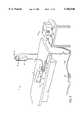
- FIG. 1is a perspective view of the electrosurgical system including an electrosurgical probe, an electrically conducting fluid supply and an electrosurgical power supply constructed in accordance with the principles of the present invention
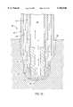
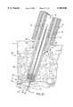
- FIG. 2Ais an enlarged, cross-sectional view of the distal tip of the electrosurgical probe of FIG. 1;
- FIG. 2Bis an end view of the electrosurgical probe of FIG. 1;
- FIG. 2Cis a cross-sectional view of the proximal end of the electrosurgical probe of FIG. 2A, illustrating an arrangement for coupling the probe to the electrically conducting fluid supply of FIG. 1;
- FIGS. 2D and 2Eare cross-sectional views of the distal end of the electrosurgical probe of FIG. 2A, illustrating one method of manufacturing the electrode terminals and insulating matrix of the probe;
- FIG. 3is a perspective view of the distal tip of another electrosurgical probe that does not incorporate a fluid lumen for delivering electrically conducting fluid to the target site;
- FIG. 4Ais an enlarged, cross-sectional view of the distal tip of the electrosurgical probe of FIG. 3 illustrating an electrode array
- FIG. 4Bis an end view of the distal tip of the electrosurgical probe of FIG. 3;
- FIG. 5is a perspective view of a catheter having a shaft with an electrosurgical arrangement at its distal end;
- FIGS. 6-10Aillustrate alternative electrode arrangements for the probes of FIGS. 1-4 or the catheter of FIG. 5;
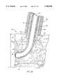
- FIG. 11is a sectional view of the human heart, illustrating the electrosurgical catheter of FIG. 5 within the ventricular cavity for performing a transmyocardial revascularization procedure;
- FIG. 12is a sectional view of the thoracic cavity, illustrating the electrosurgical probe of FIGS. 3, 4A and 4B in a thoracoscopic revascularization procedure;
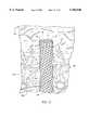
- FIG. 13is a cross-sectional view of the probe of FIGS. 3, 4A and 4B boring a channel through the myocardium;
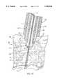
- FIG. 14is a cross-sectional view of the probe of FIGS. 1 boring a channel through the myocardium;
- FIG. 15depicts an alternative embodiment of the probe of FIG. 14 having an outer lumen for delivering electrically conductive fluid to the target site, and an inner lumen for aspirating fluid and gases from the transmyocardial channel;
- FIG. 16is a side view of an electrosurgical probe incorporating a fiberoptic viewing device and a light generator for sighting the probe onto a target site on the heart tissue;
- FIG. 17schematically illustrates a lumenal prosthesis positioned in a revascularizing channel during a percutaneous procedure to maintain lumen patency
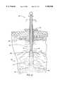
- FIG. 18is a cross-sectional view of the probe of FIG. 1 boring a channel into the myocardium with an ultrasound tissue thickness measuring device located on a guide catheter;
- FIG. 19is a cross-sectional view of the probe of FIG. 1 boring a channel into the myocardium with an ultrasound tissue thickness measuring device located on an electrosurgical catheter;
- FIG. 20is a cross-sectional view of the probe of FIG. 1 boring a channel into the myocardium with an electrical impedance sensor located on an electrosurgical catheter to detect crossing through a surface of the heart at a distance L 1 distal to the electrode array;
- FIG. 21is a schematic cross-sectional view of a hemostasis device for sealing artificial revascularizing channels formed by one of the electrosurgical instruments of the present invention.
- FIG. 22is schematically illustrates a lumenal prosthesis positioned in a revascularizing channel during a thoracoscopic procedure to maintain lumen patency
- FIG. 23schematically illustrates a curved revascularizing channel formed by one of the electrosurgical instruments of the present invention
- FIG. 24is an anterior view of a right knee joint with the patella removed
- FIG. 25is a top sectional view of the right knee joint, illustrating a "bucket-handle” lesion in the meniscus, and a plurality of surgical implants for fixing the meniscus in place during healing;
- FIG. 26illustrates a method of performing a meniscus revascularization procedure in conjunction with the meniscus repair procedure of FIG. 25 according to the present invention.
- the present inventionprovides systems, apparatus and methods for selectively applying electrical energy to a target location within or on a patient's body.
- the present inventionprovides systems, devices and methods for increasing the blood flow to a region of tissue.
- blood flowis increased within the heart by creating artificial channels or lumens through the myocardium of the heart.
- blood flowis increased to inner aspects of the meniscus by creating artificial channels or lumens from the outer aspect of the meniscus (which usually has a blood supply) to the inner aspect of the meniscus.
- the systems, devices and methodscan be applied equally well to procedures involving other tissues of the body, as well as to other procedures including open procedures, intravascular procedures, urology, laparascopy, arthroscopy, thoracoscopy or other cardiac procedures, dermatology, orthopedics, gynecology, otorhinolaryngology, spinal and neurologic procedures, oncology and the like.
- procedures involving other tissues of the bodyincluding open procedures, intravascular procedures, urology, laparascopy, arthroscopy, thoracoscopy or other cardiac procedures, dermatology, orthopedics, gynecology, otorhinolaryngology, spinal and neurologic procedures, oncology and the like.
- the remaining disclosurewill be directed specifically to the revascularization of heart and meniscus tissue.
- high frequency (RF) electrical energyis applied to one or more electrode terminals in the presence of electrically conductive fluid to remove and/or modify the structure of tissue structures.
- the present inventionmay be used to: (1) volumetrically remove tissue, bone or cartilage (i.e., ablate or effect molecular dissociation of the tissue structure); (2) form holes, channels, divots or other spaces within tissue (3) cut or resect tissue; (4) shrink or contract collagen connective tissue; and/or (5) coagulate severed blood vessels.
- the tissueis volumetrically removed or ablated.
- a high frequency voltage differenceis applied between one or more electrode terminal(s) and one or more return electrode(s) to develop high electric field intensities in the vicinity of the target tissue.
- the high electric field intensities adjacent the electrode terminal(s)lead to electric field induced molecular breakdown of target tissue through molecular dissociation (rather than thermal evaporation or carbonization).
- Applicantbelieves that the tissue structure is volumetrically removed through molecular disintegration of larger organic molecules into smaller molecules and/or atoms, such as hydrogen, oxygen, oxides of carbon, hydrocarbons and nitrogen compounds. This molecular disintegration completely removes the tissue structure, as opposed to dehydrating the tissue material by the removal of fluid within the cells of the tissue, as is typically the case with electrosurgical desiccation and vaporization.
- the high electric field intensitiesmay be generated by applying a high frequency voltage that is sufficient to vaporize an electrically conducting fluid over at least a portion of the electrode terminal(s) in the region between the distal tip of the electrode terminal(s) and the target tissue.
- the electrically conductive fluidmay be a liquid, such as isotonic saline or blood, delivered to the target site, or a viscous fluid, such as a gel, applied to the target site. Since the vapor layer or vaporized region has a relatively high electrical impedance, it increases the voltage differential between the electrode terminal tip and the tissue and causes ionization within the vapor layer due to the presence of an ionizable species (e.g., sodium when isotonic saline is the electrically conducting fluid).
- an ionizable speciese.g., sodium when isotonic saline is the electrically conducting fluid.
- This ionizationinduces the discharge of energetic electrons and photons from the vapor layer and to the surface of the target tissue.
- This energymay be in the form of energetic photons (e.g., ultraviolet radiation), energetic particles (e.g., electrons) or a combination thereof.
- energetic photonse.g., ultraviolet radiation
- energetic particlese.g., electrons
- CoblationTMA more detailed description of this phenomena, termed CoblationTM can be found in commonly assigned U.S. Pat. No. 5,683,366 the complete disclosure of which is incorporated herein by reference.
- the present inventionapplies high frequency (RF) electrical energy in an electrically conducting fluid environment to remove (i.e., resect, cut or ablate) a tissue structure, and to seal transected vessels within the region of the target tissue.
- RFhigh frequency
- the present inventionis particularly useful for sealing larger arterial vessels, e.g., on the order of 1 mm or greater.
- a high frequency power supplyis provided having an ablation mode, wherein a first voltage is applied to an electrode terminal sufficient to effect molecular dissociation or disintegration of the tissue, and a coagulation mode, wherein a second, lower voltage is applied to an electrode terminal (either the same or a different electrode) sufficient to achieve hemostasis of severed vessels within the tissue.
- an electrosurgical instrumenthaving one or more coagulation electrode(s) configured for sealing a severed vessel, such as an arterial vessel, and one or more electrode terminals configured for either contracting the collagen fibers within the tissue or removing (ablating) the tissue, e.g., by applying sufficient energy to the tissue to effect molecular dissociation.
- the coagulation electrode(s)may be configured such that a single voltage can be applied to coagulate with the coagulation electrode(s), and to ablate with the electrode terminal(s).
- the power supplyis combined with the coagulation instrument such that the coagulation electrode is used when the power supply is in the coagulation mode (low voltage), and the electrode terminal(s) are used when the power supply is in the ablation mode (higher voltage).
- the present inventionis also useful for removing or ablating tissue around nerves, such as spinal, visceral or cranial nerves, e.g., the olfactory nerve on either side of the nasal cavity, the optic nerve within the optic and cranial canals, the palatine nerve within the nasal cavity, soft palate, uvula and tonsil, etc.
- nervessuch as spinal, visceral or cranial nerves, e.g., the olfactory nerve on either side of the nasal cavity, the optic nerve within the optic and cranial canals, the palatine nerve within the nasal cavity, soft palate, uvula and tonsil, etc.
- nervessuch as spinal, visceral or cranial nerves, e.g., the olfactory nerve on either side of the nasal cavity, the optic nerve within the optic and cranial canals, the palatine nerve within the nasal cavity, soft palate, uvula and tonsil, etc.
- one or more electrode terminalsare brought into close proximity to tissue at a target site, and the power supply is activated in the ablation mode such that sufficient voltage is applied between the electrode terminals and the return electrode to volumetrically remove the tissue through molecular dissociation, as described below.
- the power supplyis activated in the ablation mode such that sufficient voltage is applied between the electrode terminals and the return electrode to volumetrically remove the tissue through molecular dissociation, as described below.
- vessels within the tissuewill be severed. Smaller vessels will be automatically sealed with the system and method of the present invention. Larger vessels, and those with a higher flow rate, such as arterial vessels, may not be automatically sealed in the ablation mode. In these cases, the severed vessels may be sealed by activating a control (e.g., a foot pedal) to reduce the voltage of the power supply into the coagulation mode.
- a controle.g., a foot pedal
- the electrode terminalsmay be pressed against the severed vessel to provide sealing and/or coagulation of the vessel.
- a coagulation electrode located on the same or a different instrumentmay be pressed against the severed vessel.
- the electrosurgical instrumentwill comprise a shaft having a proximal end and a distal end which supports an active electrode.
- the shaftmay assume a wide variety of configurations, with the primary purpose being to mechanically support one or more active electrode and permit the treating physician to manipulate the electrode(s) from a proximal end of the shaft.
- an electrosurgical probe shaftwill be a narrow-diameter rod or tube, more usually having dimensions which permit it to be introduced into a body cavity, such as the thoracic cavity, through an associated trocar or cannula in a minimally invasive procedure, such as arthroscopic, laparoscopic, thoracoscopic, and other endoscopic procedures.
- the probe shaftwill typically have a length of at least 5 cm for open procedures and at least 10 cm, more typically being 20 cm, or longer for endoscopic procedures.
- the probe shaftwill typically have a diameter of at least 0.5 mm and frequently in the range from 1 to 10 mm.
- the electrosurgical probemay be delivered percutaneously (endoluminally) by insertion through a conventional or specialized guide catheter, or the invention may include a catheter having an active electrode array integral with its distal end.
- the catheter shaftmay be rigid or flexible, with flexible shafts optionally being combined with a generally rigid external tube for mechanical support. Flexible shafts may be combined with pull wires, shape memory actuators, and other known mechanisms for effecting selective deflection of the distal end of the shaft to facilitate positioning of the electrode or electrode array.
- the shaftwill usually include a plurality of wires or other conductive elements running axially therethrough to permit connection of the electrode or electrode array and the return electrode to a connector at the proximal end of the shaft. Specific shaft designs will be described in detail in connection with the figures hereinafter.
- the electrode terminal(s)are preferably supported within or by an inorganic insulating support positioned near the distal end of the instrument shaft, e.g., a catheter body.
- the return electrodemay be located on the instrument shaft, on another instrument or on the external surface of the patient (i.e., a dispersive pad).
- a bipolar designis more preferable because this minimizes the current flow through heart tissue.
- the return electrodeis preferably either integrated with the catheter body, or another instrument located in close proximity to the distal end of the catheter body.
- the proximal end of the catheterwill include the appropriate electrical connections for coupling the return electrode(s) and the electrode terminal(s) to a high frequency power supply, such as an electrosurgical generator.
- the current flow path between the electrode terminals and the return electrode(s)may be generated by submerging the tissue site in an electrical conducting fluid (e.g., within a viscous fluid, such as an electrically conductive gel) or by directing an electrically conducting fluid along a fluid path to the target site (i.e., a liquid, such as isotonic saline, or a gas, such as argon).
- an electrical conducting fluide.g., within a viscous fluid, such as an electrically conductive gel
- a fluid pathi.e., a liquid, such as isotonic saline, or a gas, such as argon.
- the conductive gelmay also be delivered to the target site to achieve a slower more controlled delivery rate of conductive fluid.
- the viscous nature of the gelmay allow the surgeon to more easily contain the gel around the target site (e.g., rather than attempting to contain isotonic saline).
- a liquid electrically conductive fluide.g., isotonic saline
- isotonic salinemay be used to concurrently "bathe" the target tissue surface to provide an additional means for removing any tissue, and to cool the region of the target tissue ablated in the previous moment.
- the power supplymay include a fluid interlock for interrupting power to the electrode terminal(s) when there is insufficient conductive fluid around the electrode terminal(s). This ensures that the instrument will not be activated when conductive fluid is not present, minimizing the tissue damage that may otherwise occur.
- a fluid interlockcan be found in commonly assigned, co-pending U.S. application Ser. No. 09/058,336, filed Apr. 10, 1998 (attorney Docket No. CB-4), the complete disclosure of which is incorporated herein by reference.
- the system of the present inventionmay include one or more suction lumen(s) in the instrument, or on another instrument, coupled to a suitable vacuum source for aspirating fluids from the target site.
- the instrumentalso includes one or more aspiration electrode(s) coupled to the aspiration lumen for inhibiting clogging during aspiration of tissue fragments from the surgical site.
- aspiration electrode(s)coupled to the aspiration lumen for inhibiting clogging during aspiration of tissue fragments from the surgical site.
- suctionit may be desirable to contain the excess electrically conductive fluid, tissue fragments and/or gaseous products of ablation at or near the target site with a containment apparatus, such as a basket, retractable sheath or the like.
- a containment apparatussuch as a basket, retractable sheath or the like.
- This embodimenthas the advantage of ensuring that the conductive fluid, tissue fragments or ablation products do not flow into the heart or lungs.
- the present inventionmay use a single electrode or an electrode array distributed over a distal contact surface of the electrosurgical instrument.
- the circumscribed area of the electrode or electrode arraywill generally depend on the desired diameter of the revascularizing channel. For example, applicant has found that smaller diameter channels tend to remain patent for a shorter period of time than larger diameter channels. Thus, a relatively large diameter channel (on the order of about 1.5 to 3.0 mm) may be desired to improve lumen patency.
- the ability to select the diameter of the artificial channelsis one of the advantages of the present invention over existing laser procedures, which are typically limited by the concentration of light that is required to generate sufficient energy to ablate the tissue during the still or quiescent period of the heart (i.e., about 0.08 seconds).
- the area of the electrode arrayis in the range from 0.25 mm 2 to 20 mm 2 , preferably from 0.5 mm 2 to 10 mm 2 , and more preferably from about 0.5 mm 2 to 5.0 mm 2 .
- the shape of the array and the distal end of the instrument shaftwill also depend on the desired surface area of the channel. For example, the ratio of the perimeter of the electrode array to the surface area may be maximized to increase blood flow from the channel to the surrounding myocardial tissue.
- the electrode or electrodesmay take the form of a solid round wire or other solid cross-sectional shapes such as squares, rectangles, hexagons, triangles, star-shaped or the like to provide additional edges around the distal perimeter of the electrodes.
- the electrode or electrodesmay be in the form of hollow metal tubes having a cross-sectional shape which is round, square, hexagonal, rectangular or the like.
- the envelop or effective diameter of the individual electrode or electrodesranges from about 0.05 to 3 mm, preferably from about 0.1 to 2 mm.
- the electrode arraywill usually include at least one isolated electrode terminal, and in some embodiments may include at least four electrode terminals, sometimes at least six electrode terminals, and often 50 or more electrode terminals, disposed over the distal contact surfaces on the shaft.
- the present inventionmay use a single active electrode or an electrode array distributed over a distal contact surface of an electrosurgical instrument, such as a probe, a catheter or the like.
- the electrode arrayusually includes a plurality of independently current-limited and/or power-controlled electrode terminals to apply electrical energy selectively to the target tissue while limiting the unwanted application of electrical energy to the surrounding tissue and environment resulting from power dissipation into surrounding electrically conductive fluids, such as blood, normal saline, and the like.
- the electrode terminalsmay be independently current-limited by isolating the terminals from each other and connecting each terminal to a separate power source that is isolated from the other electrode terminals.
- the electrode terminalsmay be connected to each other at either the proximal or distal ends of the probe to form a single wire that couples to a power source.
- each individual electrode terminal in the electrode arrayis electrically insulated from all other electrode terminals in the array within said instrument and is connected to a power source which is isolated from each of the other electrode terminals in the array or to circuitry which limits or interrupts current flow to the electrode terminal when low resistivity material (e.g., blood, electrically conductive saline irrigant or electrically conductive gel) causes a lower impedance path between the return electrode and the individual electrode terminal.
- the isolated power sources for each individual electrode terminalmay be separate power supply circuits having internal impedance characteristics which limit power to the associated electrode terminal when a low impedance return path is encountered.
- the isolated power sourcemay be a user selectable constant current source.
- a single power sourcemay be connected to each of the electrode terminals through independently actuatable switches, or by independent current limiting elements, such as inductors, capacitors, resistors and/or combinations thereof.
- the current limiting elementsmay be provided in the instrument, connectors, cable, controller or along the conductive path from the controller to the distal tip of the instrument.
- the resistance and/or capacitancemay occur on the surface of the active electrode terminal(s) due to oxide layers which form selected electrode terminals (e.g., titanium or a resistive coating on the surface of metal, such as platinum).
- the tip region of the instrumentmay comprise many independent electrode terminals designed to deliver electrical energy in the vicinity of the tip.
- the selective application of electrical energy to the conductive fluidis achieved by connecting each individual electrode terminal and the return electrode to a power source having independently controlled or current limited channels.
- the return electrode(s)may comprise a single tubular member of conductive material proximal to the electrode array at the tip which also serves as a conduit for the supply of the electrically conducting fluid between the active and return electrodes.
- the instrumentmay comprise an array of return electrodes at the distal tip of the instrument (together with the active electrodes) to maintain the electric current at the tip.
- the application of high frequency voltage between the return electrode(s) and the electrode arrayresults in the generation of high electric field intensities at the distal tips of the electrode terminals with conduction of high frequency current from each individual electrode terminal to the return electrode.
- the current flow from each individual electrode terminal to the return electrode(s)is controlled by either active or passive means, or a combination thereof, to deliver electrical energy to the surrounding conductive fluid while minimizing energy delivery to surrounding (non-target) tissue.
- the application of a high frequency voltage between the return electrode(s) and the electrode terminal(s) for appropriate time intervalseffects cutting, removing, ablating, shaping, contracting or otherwise modifying the target tissue.
- the tissue volume over which energy is dissipatedi.e., a high current density exists
- the tissue volume over which energy is dissipatedmay be precisely controlled, for example, by the use of a multiplicity of small electrode terminals whose effective diameters or principal dimensions range from about 5 mm to 0.01 mm, preferably from about 2 mm to 0.05 mm, and more preferably from about 1 mm to 0.1 mm.
- Electrode areas for both circular and non-circular terminalswill have a contact area (per electrode terminal) below 25 mm 2 for electrode arrays and as large as 75 mm 2 for single electrode embodiments, preferably being in the range from 0.0001 mm 2 to 1 mm 2 , and more preferably from 0.005 mm 2 to 0.5 mm 2 .
- the circumscribed area of the electrode arrayis in the range from 0.25 mm 2 to 75 mm 2 , preferably from 0.5 mm 2 to 40 mm 2 , and will usually include at least one includes, often at least two isolated electrode terminals, often at least five electrode terminals, often greater than 10 electrode terminals and even 50 or more electrode terminals, disposed over the distal contact surfaces on the shaft.
- the use of small diameter electrode terminalsincreases the electric field intensity and reduces the extent or depth of tissue heating as a consequence of the divergence of current flux lines which emanate from the exposed surface of each electrode terminal.
- the area of the tissue treatment surfacecan vary widely, and the tissue treatment surface can assume a variety of geometries, with particular areas and geometries being selected for specific applications.
- the active electrode surface(s)can have area(s) in the range from 0.25 mm 2 to 75 mm 2 , usually being from about 0.5 mm 2 to 40 mm 2 .
- the geometriescan be planar, concave, convex, hemispherical, conical, linear "in-line” array or virtually any other regular or irregular shape.
- the active electrode(s) or electrode terminal(s)will be formed at the distal tip of the electrosurgical instrument shaft, frequently being planar, disk-shaped, or hemispherical surfaces for use in reshaping procedures or being linear arrays for use in cutting.
- the active electrode(s)may be formed on lateral surfaces of the electrosurgical instrument shaft (e.g., in the manner of a spatula), facilitating access to certain body structures in endoscopic procedures.
- the electrode support and the fluid outletmay be recessed from an outer surface of the instrument or handpiece to confine the electrically conductive fluid to the region immediately surrounding the electrode support.
- the shaftmay be shaped so as to form a cavity around the electrode support and the fluid outlet. This helps to assure that the electrically conductive fluid will remain in contact with the electrode terminal(s) and the return electrode(s) to maintain the conductive path therebetween. In addition, this will help to maintain a vapor layer and subsequent plasma layer between the electrode terminal(s) and the tissue at the treatment site throughout the procedure, which reduces the thermal damage that might otherwise occur if the vapor layer were extinguished due to a lack of conductive fluid. Provision of the electrically conductive fluid around the target site also helps to maintain the tissue temperature at desired levels.
- the electrically conducting fluidshould have a threshold conductivity to provide a suitable conductive path between the return electrode and the electrode terminal(s).
- the electrical conductivity of the fluid(in units of milliSiemans per centimeter or mS/cm) will usually be greater than 0.2 mS/cm, preferably will be greater than 2 mS/cm and more preferably greater than 10 mS/cm.
- the electrically conductive fluidis isotonic saline, which has a conductivity of about 17 mS/cm.
- the voltage difference applied between the return electrode(s) and the electrode terminal(s)will be at high or radio frequency, typically between about 5 kHz and 20 MHz, usually being between about 30 kHz and 2.5 MHz, preferably being between about 50 kHz and 500 kHz, more preferably less than 350 kHz, and most preferably between about 100 kHz and 200 kHz.
- the RMS (root mean square) voltage appliedwill usually be in the range from about 5 volts to 1000 volts, preferably being in the range from about 10 volts to 500 volts depending on the electrode terminal size, the operating frequency and the operation mode of the particular procedure or desired effect on the tissue (i.e., contraction, coagulation, cutting or ablation).
- the peak-to-peak voltage for ablation or cuttingwill be in the range of 10 to 2000 volts and preferably in the range of 200 to 1800 volts and more preferably in the range of about 300 to 1500 volts, often in the range of about 500 to 900 volts peak to peak (again, depending on the electrode size, the operating frequency and the operation mode).
- Lower peak-to-peak voltageswill be used for tissue coagulation or collagen contraction and will typically be in the range from 50 to 1500, preferably 100 to 1000 and more preferably 120 to 600 volts peak-to-peak.
- the voltageis usually delivered in a series of voltage pulses or alternating current of time varying voltage amplitude with a sufficiently high frequency (e.g., on the order of 5 kHz to 20 MHz) such that the voltage is effectively applied continuously (as compared with e.g., lasers claiming small depths of necrosis, which are generally pulsed about 10 to 20 Hz).
- the duty cyclei.e., cumulative time in any one-second interval that energy is applied
- the electrosurgical instrumentwill usually bore a channel completely through the heart wall in about 0.5 to 20.0 seconds, preferably about 1.0 to 3.0 seconds, in the continuous mode and preferably about 10 to 15 seconds in the pulsed mode. It has been found that channels that are approximately 0.5 to 3.0 mm in diameter and approximately 1 to 4 cm deep may be easily and efficiently formed by this method, and that the revascularization procedure dramatically improves the flow of blood to the heart muscle.
- CO 2 lasers used for LMRtypically deliver the power for each channel within an elapsed time of 0.08 seconds.
- the present inventioncan be used to complete the canalization of the same sized channel within about 1.0 second.
- the laserrequires about 500 to 700 watts to form a 1 mm diameter channel while the present invention requires 1/12 or about 42 to 58 watts to form the same channel. If larger channels are required, the power requirements increase by the square of the ratio of diameters.
- the present inventioncan form a 2 mm diameter channel (of the same length as above) in 1 second with an applied power of about 168 to 232 watts.
- the preferred power source of the present inventiondelivers a high frequency current selectable to generate average power levels ranging from several milliwatts to tens of watts per electrode, depending on the volume of target tissue being heated, and/or the maximum allowed temperature selected for the instrument tip.
- the power sourceallows the user to select the voltage level according to the specific requirements of a particular cardiac surgery, arthroscopic surgery, dermatological procedure, ophthalmic procedures, open surgery or other endoscopic surgery procedure.
- the power sourcemay have an additional filter, for filtering leakage voltages at frequencies below 100 kHz, particularly voltages around 60 kHz.
- a description of a suitable power sourcecan be found in co-pending patent applications Ser. Nos. 09/058,571 and 09/058,336, filed Apr. 10, 1998 (Attorney Docket Nos. CB-2 and CB-4), the complete disclosure of both applications are incorporated herein by reference for all purposes.
- the power sourcemay be current limited or otherwise controlled so that undesired heating of the target tissue or surrounding (non-target) tissue does not occur.
- current limiting inductorsare placed in series with each independent electrode terminal, where the inductance of the inductor is in the range of 10 uH to 50,000 uH, depending on the electrical properties of the target tissue, the desired tissue heating rate and the operating frequency.
- capacitor-inductor (LC) circuit structuresmay be employed, as described previously in U.S. Pat. No. 5,697,909, the complete disclosure of which is incorporated herein by reference. Additionally, current limiting resistors may be selected.
- these resistorswill have a large positive temperature coefficient of resistance so that, as the current level begins to rise for any individual electrode terminal in contact with a low resistance medium (e.g., saline irrigant or blood), the resistance of the current limiting resistor increases significantly, thereby minimizing the power delivery from said electrode terminal into the low resistance medium (e.g., saline irrigant or blood).
- a low resistance mediume.g., saline irrigant or blood
- control systemis "tuned” so that it will not apply excessive power to the blood (e.g., in the ventricle), once it crosses the wall of the heart and enters the chamber of the left ventricle. This minimizes the formation of a thrombus in the heart (i.e., will not induce thermal coagulation of the blood).
- the control systemmay include an active or passive architecture, and will typically include a mechanism for sensing resistance between a pair(s) of active electrodes at the distal tip, or between one or more active electrodes and a return electrode, to sense when the electrode array has entered into the blood-filled chamber of the left ventricle.
- current limiting meansmay be provided to prevent sufficient joulean heating in the lower resistivity blood to cause thermal coagulation of the blood.
- an ultrasound transducer at the tip of the instrumentcan be used to detect the boundary between the abnormal tissue layer and healthy underlying tissue.
- the inventionis not limited to electrically isolated electrode terminals, or even to a plurality of electrode terminals.
- the array of active electrode terminalsmay be connected to a single lead that extends through the catheter shaft to a power source of high frequency current.
- the cathetermay incorporate a single electrode that extends directly through the catheter shaft or is connected to a single lead that extends to the power source.
- the active electrode(s)may have ball shapes (e.g., for tissue vaporization and desiccation), twizzle shapes (for vaporization and needle-like cutting), spring shapes (for rapid tissue debulking and desiccation), twisted metal shapes, annular or solid tube shapes or the like.
- the electrode(s)may comprise a plurality of filaments, rigid or flexible brush electrode(s) (for debulking a tumor, such as a fibroid, bladder tumor or a prostate adenoma), side-effect brush electrode(s) on a lateral surface of the shaft, coiled electrode(s) or the like.
- an electrosurgical catheter or probecomprises a single active electrode terminal that extends from an insulating member, e.g., ceramic, at the distal end of the shaft.
- the insulating memberis preferably a tubular structure that separates the active electrode terminal from a tubular or annular return electrode positioned proximal to the insulating member and the active electrode.
- the catheter or probeincludes a single active electrode that can be rotated relative to the rest of the catheter body, or the entire catheter may be rotated related to the lead.
- the single active electrodecan be positioned adjacent the abnormal tissue (e.g., calcified deposits) and energized and rotated as appropriate to remove this tissue.
- Electrosurgical system 11generally comprises an electrosurgical instrument or probe or catheter 10 connected to a power supply 28 for providing high frequency voltage to electrosurgical instrument 10 and a fluid source 21 provided for supplying electrically conducting fluid 50 to probe 10.
- electrosurgical probe 10includes an elongated shaft 13 which may be flexible or rigid, with flexible shafts optionally including support cannulas or other structures (not shown). It will be recognized that the probe shown in FIG. 1 will generally be employed in open or thoracoscopic procedures through intercostal penetrations in the patient. For endoluminal procedures into the ventricle, a delivery catheter 200 (FIGS. 6 and 11) will typically be employed, as discussed below. Probe 10 includes a connector 19 at its proximal end and an array 12 of electrode terminals 58 disposed on the distal tip of shaft 13. A connecting cable 34 has a handle 22 with a connector 20 which can be removably connected to connector 19 of probe 10.
- the proximal portion of cable 34has a connector 26 to removably couple probe 10 to power supply 28.
- the electrode terminals 58are electrically isolated from each other and each of the terminals 58 is connected to an active or passive control network within power supply 28 by means of a plurality of individually insulated conductors 42 (see FIG. 2A).
- Power supply 28has a selection means 30 to change the applied voltage level.
- Power supply 28also includes means for energizing the electrodes 58 of probe 10 through the depression of a pedal 39 in a foot pedal 37 positioned close to the user.
- the foot pedal 37may also include a second pedal (not shown) for remotely adjusting the voltage level applied to electrodes 58.
- the electrically isolated electrode terminals 58are spaced-apart over an electrode array surface 82.
- the electrode array surface 82 and individual electrode terminals 58will usually have dimensions within the ranges set forth above.
- the electrode array surface 82has a circular cross-sectional shape with a diameter D (FIG. 2B) in the range from 0.3 mm to 4 mm.
- Electrode array surface 82may also have an oval or rectangular shape, having a length L in the range of 1 mm to 20 mm and a width W in the range from 0.3 mm to 7 mm, as shown in FIG. 8 (discussed below).
- the individual electrode terminals 58will protrude over the electrode array surface 82 by a distance (H) from 0 mm to 2 mm, preferably from 0 mm to 1 mm (see FIG. 2A).
- the electrode terminals 58are preferably composed of a electrically conductive metal or alloy, such as platinum, titanium, tantalum, tungsten, niobium, stainless steel, and the like.
- a preferred material for terminals 58is tungsten because of its known bicompatibility and resistance to erosion under the application of high voltages.
- the electrode terminals 58are anchored in a support matrix 48 of suitable insulating material (e.g., ceramic, glass/ceramic, or glass material, such as alumina, silica glass and the like) which could be formed at the time of manufacture in a flat, hemispherical or other shape according to the requirements of a particular procedure.
- the support matrix 48will comprise an inorganic insulator, such as ceramic, glass, glass/ceramic or a high resistivity material, such as silicon or the like.
- An inorganic materialis generally preferred for the construction of the support matrix 48 since organic or silicone based polymers are known to rapidly erode during sustained periods of the application of high voltages between electrode terminals 58 and the return electrode 56 during tissue ablation. However, for situations in which the total cumulative time of applied power is less than about one minute, organic or silicone based polymers may be used without significant erosion and loss of material of the support matrix 48 and, therefore, without significant reduction in ablation performance.
- support matrix 48is adhesively joined to support member 9, which extends most or all of the distance between matrix 48 and the proximal end of probe 10.
- support matrix 48comprises a plurality of glass or ceramic hollow tubes 400 (FIG. 2D) extending from the distal end of shaft 13.
- electrode terminals 58are each inserted into the front end of one of the hollow tubes 400 and adhered to the hollow tubes 400 so that the terminals 58 extend distally from each hollow tube 400 by the desired distance, H.
- the terminals 58are preferably bonded to the hollow tubes 400 by a sealing material 402 (e.g., epoxy) selected to provide effective electrical insulation, and good adhesion to both the hollow tubes 400 and the electrode terminals 58.
- a sealing material 402e.g., epoxy
- hollow tubes 400may be comprised of a glass having a coefficient of thermal expansion similar to that of electrode terminal 58 and may be sealed around the electrode terminal 58 by raising the temperature of the glass tube to its softening point according to the procedures commonly used to manufacture glass-to-metal seals.
- lead wires 406, such as insulation 408 covered copper wiresare inserted through the back end of the hollow tubes 400 and coupled to the terminals 58 with a suitable conductive adhesive 404.
- the lead wire 406 and electrode terminal 58may be constructed of a single wire (e.g., stainless steel or nickel alloy) with insulation 408 removed over the length of the wire inserted into the hollow tube 400.
- sealing material 402is used to seal annular gaps between hollow tube 400 and electrode terminal 58 and to adhesively join electrode terminal 58 to hollow tube 400. Other features of construction are discussed above and shown in FIG. 2E.
- probe 10includes a return electrode 56 for completing the current path between electrode terminals 58 and power supply 28.
- Shaft 13preferably comprises an electrically conducting material, usually metal, which is selected from the group consisting of stainless steel alloys, platinum or its alloys, titanium or its alloys, molybdenum or its alloys, and nickel or its alloys.
- the return electrode 56may be composed of the same metal or alloy which forms the electrode terminals 58 to minimize any potential for corrosion or the generation of electrochemical potentials due to the presence of dissimilar metals contained within an electrically conductive fluid 50, such as isotonic saline (discussed in greater detail below).
- return electrode 56extends from the proximal end of probe 10, where it is suitably connected to power supply 28 via connectors 19, 20, to a point slightly proximal of electrode array surface 82, typically about 0.5 to 10 mm and more preferably about 1 to 10 mm.
- Shaft 13is disposed within an electrically insulative jacket 18, which is typically formed as one or more electrically insulative sheaths or coatings, such as polyester, polytetrafluoroethylene, polyimide, and the like.
- the provision of the electrically insulative jacket 18 over shaft 13prevents direct electrical contact between shaft 13 and any adjacent body structure or the surgeon. Such direct electrical contact between a body structure and an exposed return electrode 56 could result in unwanted heating and necrosis of the structure at the point of contact causing necrosis.
- return electrode 56is not directly connected to electrode terminals 58.
- electrically conducting fluid 50e.g., isotonic saline
- a fluid path 83is formed by annular gap 54 between outer return electrode 56 and tubular support member 78.
- An additional fluid path 83may be formed between an optional inner lumen 57 within an inner tubular member 59.
- the electrically conducting fluid 50 flowing through fluid paths 83provides a pathway for electrical current flow between target tissue 52 and return electrode 56, as illustrated by the current flux lines 60 in FIG. 2A.
- FIG. 2Cillustrates the proximal or connector end 70 of probe 10 in the embodiment of FIGS. 2A and 2B.
- Connector 19comprises a plurality of individual connector pins 74 positioned within a housing 72 at the proximal end 70 of probe 10. Electrode terminals 58 and the attached insulating conductors 42 extend proximally to connector pins 74 in connector housing 72.
- Return electrode 56extends into housing 72, where it bends radially outward to exit probe 10.
- a fluid supply tube 15removably couples fluid source 21, (e.g., a bag of electrically conductive fluid elevated above the surgical site or having a pumping device), with return electrode 56.
- fluid source 21e.g., a bag of electrically conductive fluid elevated above the surgical site or having a pumping device
- an insulating jacket 14covers the exposed portions of electrode 56.
- One of the connector pins 76is electrically connected to return electrode 56 to couple electrode 56 to power supply 28 via cable 34.
- a manual control valve 17may also be provided between the proximal end of electrode 56 and supply tube 15 to allow the surgical team to regulate the flow of electrically conducting fluid 50.
- FIGS. 3, 4A and 4Billustrate another preferred embodiment of the present invention.
- the probedoes not include a fluid channel for directing electrically conducting fluid to the target site.
- the fluids in the patient's heart tissuesuch as blood, usually have a sufficient amount of electrical conductivity to complete the electrical path between the active electrode array and the return electrodes.
- these fluidswill often have the requisite properties discussed above for establishing a vapor layer, creating regions of high electric fields around the edges of electrode terminals 58 and inducing the discharge of energetic electrons and photons from the vapor layer to the surface of the target tissue to effect ablation.
- electrosurgical probe 100has a shaft 102 with an exposed distal end 104 and a proximal end (not shown) similar to the proximal end shown in FIG. 2C. Aside from exposed distal end 104, which functions as the return electrode in this embodiment, the entire shaft 102 is preferably covered with an electrically insulative jacket 106, which is typically formed as one or more electrically insulative sheaths or coatings, such as polyester, polytetrafluoroethylene, polyimide, and the like, to prevent direct electrical contact between shaft 102 and any adjacent body structure or the surgeon. Similar to the previous embodiment, probe 100 includes an array 108 of active electrode terminals 110 having substantially the same applied potential.
- Terminals 110extend from the an insulating inorganic matrix 112 attached to distal end 104 of shaft 102.
- matrix 112is only shown schematically in the drawings, and preferably comprises an array of glass or ceramic tubes extending from distal end 104 or is a ceramic spacer through which electrode terminals 110 extend.
- the electrode arraymay have a variety of different configurations other than the one shown in FIGS. 3, 4A and 4B.
- the distal end of the shaft 102 and/or the insulating matrixmay have a substantially rectangular shape with rounded corners so as to maximize the perimeter length to cross-sectional area ratio of the distal tip of the probe.
- electrode array surface 120has a rectangular shape having a width in the range of 2 mm to 5 mm and a height in the range of 1 mm to 2 mm.
- Increasing the perimeter of the artificial channelmay have advantages in revascularizing tissue because the blood flowing through the artificial channel will have a greater area to pass into the tissue for a given cross-sectional area. Thus, this configuration is a more efficient method of increasing blood flow to a region of tissue.
- the return electrodeis positioned on the front or distal face of the probe. This configuration inhibits current flow within the tissue on the sides of probe as it forms the revascularizing channel.
- the electrode array surface 122includes multiple pairs of electrodes, with each pair of electrodes including an active electrode 126 and a return electrode 128. Thus, as shown, the high frequency current passes between the pairs across the distal surface 122 of the probe.
- the return or common electrode 130is positioned in the center of the distal probe surface 132 and the active electrodes 134 are positioned at its perimeter.
- the electrosurgical currentwill flow between active electrodes 134 at the perimeter of distal surface 132 and return electrode 130 at its center to form the revascularizing channel.
- Thisallows the surgeon to more precisely control the diameter of the revascularizing channel because the current will generally flow radially the outer electrodes 134 and the return electrode 130.
- electrodes 134will preferably be positioned on the perimeter of distal surface 132 (i.e., further radially outward than shown in FIG. 10A) to avoid tearing of non-ablated tissue by the perimeter of the probe shaft.
- FIG. 6illustrates yet another embodiment of an electrosurgical probe 100' according to the present invention.
- the distal tip of the probehas a conical shape and includes an array of active electrodes along the conical surface 140.
- a conical shapeprovides less resistance to the advancement of the probe through dense tissue.
- insulating matrix 142tapers in the distal direction to form conical distal surface 140.
- the electrode array 144extends from distal surface 140, with each electrode terminal 146 arranged to protrude axially from the conical surface 140 (i.e., rather than protruding perpendicularly from the surface 140).
- the electrodes 146do not extend radially outward from the conical surface 140, which reduces the risk of electric current flowing radially outward to heart tissue surrounding the revascularizing channel.
- the high electric field gradients generated by the electric currentconcentrate near the active electrode surfaces and taper further away from these surfaces. Therefore, this configuration places these high electric field gradients within the diameter of the desired channel to improve ablation of the channel, while minimizing ablation of tissue outside of the desired channel.
- FIG. 5illustrates a preferred delivery catheter 200 for introducing an electrosurgical probe 202 through a percutaneous penetration in the patient, and endoluminally delivering probe 202 to the target site (e.g., a ventricle of the heart as detail below).
- Catheter 200generally includes a shaft 206 having a proximal end 208 and a distal end 210.
- Catheter 200includes a handle 204 secured to proximal end 208 of shaft, and preferably a deflectable tip 212 coupled to distal end 210 of shaft 206.
- Probe 202extends from proximal end, preferably by a distance of about 100 to 200 cm.
- Handle 204includes a variety of actuation mechanisms for manipulating tip 212 within the patient's heart, such as a tip actuation slide 214 and a torque ring 216, as well as an electrical connector 218.
- Catheter shaft 206will generally define one or more inner lumens 220, and one or more manipulator wires and electrical connections (not shown) extending through the lumens to probe 202.
- electrosurgical probe 202is positioned into the left ventricular cavity 258 of the heart. Electrosurgical probe 202 may be introduced into the left ventricle 250 in a variety of procedures that are well known in the art, such as a percutaneous, minimally invasive procedures. In the representative embodiment, probe 202 is introduced into the vasculature of the patient through a percutaneous penetration 360 and axially translated via delivery catheter 200 through one of the major vessels, such as the femoral artery 346, through the aorta 254 to the left ventricular cavity 258. A viewing scope (not shown) may also be introduced through a percutaneous position to a position suitable for viewing the target location in the left ventricle 258.
- probe 202is aligned with the heart wall 260 to form one or more artificial channels 264 for increasing blood flow to the myocardium 262.
- the channels 264will preferably extend from the endocardium 266 a desired distance through the myocardium 262 without perforating the exterior of the epicardium 268 to inhibit blood from flowing into the thoracic cavity.
- the surgeonwill employ a detection or instrument guidance system 350, (discussed below in reference to FIGS. 16, 18, 19 and 20) on probe 202, or another instrument, to determine when the probe is near the outer surface of the epicardium 268.
- the location of channels 264may be selected based on familiar endocardial anatomic landmarks.
- instrument guide system 350may be used to select target sites on the heart wall, as discussed below.
- guide catheter 200is positioned adjacent the inner endocardial wall and probe 202 is axially translated so that the active electrode 270 at its distal end is positioned proximate the heart tissue.
- the probe 202includes a single, annular electrode 270 at its distal tip for ablation of the heart tissue.
- the probemay include an array of electrode terminals as described in detail above. While viewing the region with an endoscope (not shown), voltage can be applied from power supply 28 (see FIG. 1) between active electrode 270 and annular return electrode 272.
- the boring of channel 264is achieved by engaging active electrode 270 against the heart tissue or positioning active electrode 270 in close proximity to the heart tissue while simultaneously applying voltage from power supply 28 and axially displacing probe 202 through channel 264.
- electrically conducting irrigante.g., isotonic saline
- the electrically conducting fluidprovides a pathway for electrical current flow between the heart tissue and return electrode 272, as illustrated by the current flux lines 278 in FIG. 15.
- FIG. 15illustrates an alternative embodiment of the probe of FIG. 14.
- the probe 280includes a central lumen 282 having a proximal end attached to a suitable vacuum source (not shown) and an open distal end 286 for aspirating the target site.
- electrically conducting irrigante.g., isotonic saline
- the active electrodeis preferably a single annular electrode 288 surrounding the open distal end 286 of central lumen 282.
- Central lumen 282is utilized to remove the ablation products (e.g., fluids and gases) generated at the target site and excess electrically conductive irrigant during the procedure.
- FIG. 23An alternative embodiment of the percutaneous, endocardial canalization approach is shown in FIG. 23.
- electrosurgical catheter 100can be guided by the surgeon or surgical assistant during the canalization of channel 264 using external handpiece 340 shown in FIG. 11.
- the distal portion of the electrosurgical catheter 100can be caused to follow a curved path to effect a curved artificial channel 264'.
- the total surface area of the artificial channelcan be extended so that said channel is longer than the total thickness L 9 of the heart wall 260.
- the curved artificial channel 264'can be continued forming a complete "U" shaped channel which reenters the ventricular cavity 258 providing one continuous channel which penetrates the endocardium at two locations but does not penetrate through the epicardium 268.
- FIG. 12illustrates a thoracoscopic procedure for revascularizing the myocardium from the outer wall or epicardium 268 inward to the endocardium 266.
- At least one intercostal penetrationis made in the patient for introduction of electrosurgical probe 100 (FIG. 3) into the thoracic cavity 302.
- the term "intercostal penetration” as used hereinrefers to any penetration, in the form of a small cut, incision, hole or cannula, trocar sleeve or the like, through the chest wall between two adjacent ribs which does not require cutting, removing, or significantly displacing or retracting the ribs or sternum.
- the intercostal penetrationwill require a puncture or incision of less than about 5 cm in length.
- the intercostal penetrationwill be a trocar sleeve 300 having a length in the range from about 2-15 cm, and an internal diameter in the range from 1 to 15 mm, commonly known as thoracic trocars.
- Suitable trocar sleevesare available from United States Surgical Corp. of Norwalk, Conn., under the brand name "Thoracoport”TM.
- a viewing scope(not shown) may also be introduced through a trocar sleeve to a position suitable for viewing the target location on the heart wall 260.
- a viewing scope(not shown) may also be introduced through the same or another intercostal penetration into the thoracic cavity 302 to a position suitable for viewing the target location 360 on the surface of the epicardium 268 of the heart.
- the viewing scopecan be a conventional laparoscope or thoracoscope, which typically comprise a rigid elongated tube containing a lens system and an eyepiece or camera mount at the proximal end of the tube.
- a small video camerais preferably attached to the camera mount and connected to a video monitor to provide a video image of the procedure.
- This type of scopeis commercially available from Baxter Healthcare Corporation of Deerfield, Ill. or United States Surgical Corporation of Norwalk, Conn.
- one or more artificial channels 264are formed by the electrosurgical probe 100 from the outer wall or epicardium 268 through the myocardium 262 and the inner wall or endocardium 266 into the ventricular cavity 258.
- electrode array 108is positioned in close proximity to the heart tissue while simultaneously applying voltage from power supply 28 and axially displacing probe 100 through channel 264.
- electrically conducting fluidis not supplied to the target site to complete the current path between the active electrode terminals 110 and return electrode 102.
- the fluids in the patient's heart tissue, such as bloodusually have a sufficient amount of electrical conductivity to complete the electrical path between the active electrode array and the return electrodes.
- these fluidswill often have the requisite properties discussed above for establishing a vapor layer and inducing the discharge of energetic electrons and photons from the vapor layer to the surface of the target tissue as well as the creation of high electric fields to effect the ablation of tissue.
- the channels 264will preferably be sealed at the epicardium 268 as soon as possible after they have been formed.
- One method for sealing the artificial channel 264 at the epicardium 268is to insert a collagen hemostasis device 480 (shown in FIG. 21) using a trocar 300, a cannula 484 and a syringe-like delivery system 486.
- the collagenunaffected by antiplatelet or anticoagulant agents that may be present in the patient's blood stream, attracts and activates platelets from the blood 482, rapidly forming a "glue"-like plug near the surface of the epicardium 268 of the newly formed channel 264.
- Suitable collagen hemostasis devicesare available from Datascope Corporation, Montval, N.J. under the brand name "VasoSealTM".
- the deployment of the collagen hemostasis device 480is accomplished with the aid of a viewing scope (not shown) which may also be introduced through a trocar sleeve to a position suitable for viewing the target location on the heart wall 260.
- the electrosurgical probe 354will preferably include a guidance system 350 (FIG. 16) for determining when the probe is close to the inner surface of the endocardium 266 so that the surgeon can prepare to withdraw probe 100 and seal the channel 264.
- a guidance system 350FOG. 16
- the present inventionprovides localized ablation or disintegration of heart tissue to form a revascularization channel 264 of controlled diameter and depth.
- the diameterwill be in the range of 0.5 mm to 3 mm, preferably between about 1 to 2 mm.
- the radio frequency voltagewill be in the range of 300 to 2400 volts peak-to-peak to provide controlled rates of tissue ablation and hemostasis while minimizing the depth of necrosis of tissue surrounding the desired channel. This voltage will typically be applied continuously throughout the procedure until the desired length of the channel 264 is completely formed.
- the heartbeatmay be monitored and the voltage applied in pulses that are suitably timed with the contractions (systole) of the heart.
- Ablation of the tissuemay be facilitated by axially reciprocating and/or rotating the electrosurgical probe a distance of between about 1 to 5 mm. This axial reciprocation or rotation allows the electrically conducting fluid (FIG. 14) to flow over the tissue surface being canalized, thereby cooling this tissue and preventing significant thermal damage to the surrounding tissue cells.
- FIG. 16illustrates one representative guidance system 350 for guiding an electrosurgical probe 354 to target sites on the heart wall.
- Guidance system 350is provided for detecting an "end point" for each artificial channel and/or for determining appropriate target sites on the heart wall for forming the artificial channels.
- the instrument guidance system 350will preferably allow a surgeon to determine when the electrosurgical probe 354 (or an electrosurgical catheter) is near the other end of the heart wall (i.e., the outer edge of the epicardium or the inner edge of the endocardium).
- the guidance system 350indicates to the surgeon to stop axially translating the probe 354 so that the probe does not form a channel completely through a heart wall, which limits bleeding and/or reduces damage to surrounding tissue structures or blood.
- the guidance system 354will allow the surgeon to determine an appropriate target site 360 on the heart wall to form the channel to avoid accidental puncturing of relatively large vessels in the heart wall.
- the instrument guidance system 350includes a fiberoptic viewing cable 356 within electrosurgical probe 354, and a visible light generator 358, such as a laser beam, integral with the probe for illuminating a target site 360 on the heart wall.
- a visible light generator 358such as a laser beam
- both light generator 358 and fiberoptic cable 356may be coupled to an instrument other than probe 354.
- the fiberoptic viewing cable 356sites the target site 360 illuminated by the visible light generator 358 to locate where the probe 354 will bore the hole. This allows the surgeon to avoid puncturing larger blood vessels 362 on the heart wall (e.g., coronary arteries or veins).
- Visible light generator 358may also be used to determine when the distal end 364 of probe 354 is close to the opposite side of the heart wall, or when the probe 354 has completely penetrated through the heart wall into the ventricular cavity 258.
- the detection systemis an ultrasound guidance system that transmits sound waves onto the heart wall to facilitate canalization of the heart.
- an ultrasound tissue thickness measuring systemmay be incorporated within the electrosurgical catheter 100 or guide tube 200 to measure the thickness of the heart wall 260 adjacent to the distal probe tip 270 and thereby allow the surgeon to pre-set the depth of each channel using adjustable stop 352 on handpiece 340 (FIG. 11) before energizing the electrosurgical catheter 100 and ablating the heart tissue.
- adjustable stop 352 on handpiece 340FIG. 11
- an ultrasonic transducer 310affixed to the distal end of guide tube 200 and connected to an external ultrasonic generator and sensing system (not shown) via lead 312, transmits pulses of ultrasound into the heart tissue in the form of emitted ultrasound signal 314 and the ultrasound generator and sensing system measures the delay time for reflected ultrasound signal 316 to return from the boundary of the heart wall at the surface of epicardium 268.
- This delay timecan be translated into a thickness of the entire heart wall and allow the surgeon to adjust the maximum travel distance of electrosurgical catheter 100 using mechanical stop 352 (FIG. 11) to prevent the length of channel 264 from extending through the outer surface of the epicardium 268.
- the surgeoncan choose to stop the canalization of the heart at any selected distance of the epicardium which may typically be in the range from about 1 mm to 10 mm.
- a third embodimentis shown in FIG. 19 wherein an ultrasonic transducer 310 is affixed to the distal end of electrosurgical catheter 100 and connected to an external ultrasonic generator and sensing system (not shown) via leads 312, and transmits pulses of ultrasound into the heart tissue in the form of emitted ultrasound signal 314.
- the ultrasound generator and sensing systemmeasures the delay time for reflected ultrasound signal 316 to return from the boundary of the heart wall at the surface of epicardium 268. This measured delay time can be translated into the distance between the distal tip 270 of electrosurgical catheter 100 and the surface of the epicardium 268. In this arrangement, the surgeon can observe where the channel 264 reaches the preferred distance from the epicardium 268 and interrupt the application of power and advancement of electrosurgical catheter 100.
- the preferred minimum thickness of the uncanalized heart wall 260(i.e., the minimum distance from the bottom of channel 264 to the surface of the epicardium 268) can be preselected by the surgeon. When this distance is reached based on the thickness of the uncanalized heart wall measured using the ultrasonic generator and sensor system (now shown), the ultrasonic generator and sensor system provides an electrical signal to the power source for the electrosurgical catheter 100 to interrupt the applied voltage, thereby ending the canalization process and limiting the depth of channel formed. In this manner, the surgeon may hear an audible tone and will "feel" the catheter advancement stop at the moment the applied voltage is interrupted.
- electrosurgical catheter 100includes a small diameter tissue electrical impedance measurement sensor 319 which extends distal to the tissue ablating electrode array 270 by a distance L 6 .
- the impedance measurement sensor 319detects the outer surface of the epicardium 268 as it enters a region of different electrical impedance (viz, the fluid-filled cavity surrounding the heart).
- sensor tip 320may include a first impedance measurement electrode 321 and a second impedance measurement electrode 323.
- a small, high-frequency potentialis applied between first and second impedance measurement electrodes 321 and 323 causing current flow between first and second impedance measurement electrodes 321 and 323 as indicated by current flux lines 322.
- the change in the electrical impedanceis measured and may be indicated by an audible signal and/or may be used as a direct feedback control signal to interrupt the application of voltage to the electrosurgical catheter 100 by generator 28 (FIG. 1).
- the forward advancement of the electrosurgical catheter 100can be limited to a preselected distance L 6 between the bottom of channel 264 and the surface of the epicardium 268.
- the guidance systemutilizes impedance measurement circuitry integrated with the ablating electrodes 110 to detect when the electrosurgical catheter probe 100 is adjacent blood vessels and/or the outer or inner boundaries of the heart wall.
- the current limiting circuitryincludes a number of impedance monitors coupled to each electrode terminal to determine the impedance between the individual electrode terminal 110 and the return of common electrode 102.
- the applied voltagewill be interrupted to avoid power delivery to blood filled ventricular cavity 258 of the heart, thereby avoiding formation of a thrombus or damage to other tissue structures within the ventricular cavity 258.
- FIG. 17illustrates a method for implanting a luminal prosthesis, such as a stent or stent-graft 370, into the artificial channels 264 formed by one of the electrosurgical probes or catheters of the present invention to maintain the patency of these channels 264.
- the stents 370are usually compressed into a narrow-diameter configuration (not shown), and advanced endoluminally to one of the artificial channels 264 in the heart wall with a conventional or specialized delivery catheter (not shown).
- the electrosurgical probemay be designed to delivery and implant the stents 370 at the target site.
- the stents 370will typically comprise a resilient, radially compressible, tubular frame 372 having a proximal end 374, a distal end 376, and an axial lumen 380 therebetween.
- the tubular frame 372includes a plurality of openings or slots (not shown) that allow it to be expanded radially outward into the enlarged configuration shown in FIG. 17 by conventional methods, such as shape memory alloys, expandable balloons, and the like.
- the stent 370exerts a radial force against the inner channel walls 382 to maintain lumen patency and/or mechanically augment luminal wall strength, thereby maintaining the blood flow from the ventricular cavity to the myocardium.
- the stent 370may also include a graft or liner 384 for inhibiting cell proliferation and occlusion through the openings and slots of frame 372.
- the stent 370is introduced into the artificial channel 264 during a percutaneous procedure as illustrated in FIG. 11. in this embodiment, the length of each channel 264 and hence the length of each stent 370 extends only partially through the entire thickness of heart wall 260.
- the stentis introduced into the artificial channel 264 during a thoracoscopic procedure as illustrated in FIG. 12.
- the length of each artificial channel 264extends completely through the heart wall 260 to allow the blood within the ventricular cavity 258 to circulate within the majority of the length of the artificial channel 264.
- the stent 370is placed in the distal portion of the artificial channel 264 as shown in FIG. 22 extending to the endocardium 266 to maintain patency of the artificial channel 264 over length L 7 of heart wall 260.
- the proximal portion of artificial channel 264may be sealed using collagen hemostasis device 480, or the like, as described hereinbefore related to FIG. 21 using a cannula 484 and syringe-like delivery system 486 as shown in FIG. 21.
- the collagen hemostasis device 480attracts and activates platelets from the blood 482, rapidly forming a "glue"-like plug near the surface of the epicardium 268 of the newly formed artificial channel 264.
- a collagen hemostasis devicemay be deployed through a central lumen 59 integral with the electrosurgical probe or catheter as illustrated in FIG. 2A.
- the collagen hemostasis devicecan be compressed to fit within a lumen 59 whose diameter is smaller than that of the artificial channel 264.
- the collagen hemostasis device 480expands to fill the full diameter of the artificial channel 264 over length L 8 as shown in FIG. 22.
- such a system for the deployment of a collagen hemostasis device 480 or the likemay be integrated with the electrosurgical catheter 100 used for the percutaneous canalization of artificial channels 264 according to method illustrated in FIG. 11. Referring to FIGS. 2A, 11 and 22, in a percutaneous approach using this sealing method, the artificial channel 264 would be formed through the entire thickness of the heart wall 260.
- a collagen hemostasis device 480 or the likeis deployed from the central lumen 59 of electrosurgical catheter 100.
- collagen hemostasis device 480expands to fill the full diameter of the artificial channel 264 over length L 8 as shown in FIG. 22 to effect a seal to prevent blood loss through the opening in the epicardium 268.
- suturing techniquesmay be employed, either percutaneously, thoracoscopically or in an open chest procedure to seal the opening of the artificial channels at the surface of the epicardium 268.
- the stent frame 372 of the present inventionis typically manufactured from a tubular material, such as tubing made out of shape memory alloy having elastic or pseudo-elastic properties, such as NitinolTM, ElgiloyTM, or the like.
- the stent framemay comprise malleable materials other than shape memory alloys, such as stainless steel.
- the stent frameswill preferably be expanded at the target site by conventional methods, e.g., an expandable balloon at the distal end of a catheter shaft.
- the tubular memberis usually significantly smaller in diameter as compared to the final diameter of the stent in the expanded configuration within the body lumen.
- Slotsmay be cut into the tubes via laser cutting methods, photo etching, or other conventional methods to form the separate stent frames.
- these methodsinclude coating the external surface of a tube with photoresist material, optically exposing the etch pattern using a laser beam while translating and rotating the part, and then chemically etching the desired slot pattern of the state using conventional techniques.
- a description of this techniquecan be found in U.S. Pat. No. 5,421,955 to Lau, the complete disclosure which is incorporated herein by reference.
- laser cutting technologyis used in conjunction with computer controlled stages to directly cut a pattern of slots in the wall of the hypodermic tubing to obtain the desired stent geometry.
- a description of a typical laser cutting methodis disclosed in U.S. Pat. No. 5,345,057 to Muller, the complete disclosure of which is incorporated herein by reference.
- the stent frame 372is formed from a resilient shape memory alloy material that is capable of being deformed by an applied stress, and then recovering to its original unstressed shape.
- the alloy materialwill usually exhibit thermoelastic behavior so that the stents will transform to the original unstressed state upon the application of heat (i.e., an A f temperature below body temperature).
- the stentsmay also exhibit stress-induced martensite, in which the martensite state is unstable and the prosthesis transforms back to the original state when a constraint has been moved (i.e., when the stent is released from an introducing catheter within a body lumen).
- the material for the shape memory alloywill be selected according to the characteristics desired of the population of prostheses.
- the shape memory alloywill comprise a nickel titanium based alloy (i.e., NitinolTM), which may include additional elements which affect the characteristics of the prosthesis, such as the temperature at which the shape transformation occurs.
- the alloymay incorporate additional metallic elements, such as copper, cobalt, vanadium, chromium, iron or the like.
- the stents 370 described above and shown in FIGS. 17 and 22are only representative of the lumenal prostheses that may be used with the present invention.
- the present inventionmay incorporate a variety of representative conventional stent structures made from metallic tubular materials that are currently marketed as implants for coronary, peripheral, biliary and other vessels including the Palmaz-SchatzTM balloon expandable stent, manufactured by Johnson and Johnson Interventional Systems, Co. and the MemothermTM stent manufactured by Angiomed, a division of C. R. Bard, Inc.
- Other stent or graft designs that can be incorporated into the present inventioninclude a coiled structure, such as that described in U.S. Pat. No.
- FIG. 24is a frontal view of a right knee joint 400 with the patella removed to illustrate the medial and lateral meniscus 402, 404, respectively.
- the meniscus 402, 404is a C-shaped piece of fibrocartilage located at the peripheral aspect of the knee joint 400 the femur 406 and the tibia 408.
- the majority of the meniscus tissuehas very little blood (particularly the inner portions of the meniscus). For that reason, when damaged, the meniscus is unable to undergo the normal healing process that occurs in most of the rest of the body. In addition, with age, the meniscus begins to deteriorate, often developing degenerative tears. Typically, when the meniscus is damaged, the torn pieces begins to move in an abnormal fashion inside the joint.
- the peripheral portion of the meniscusdoes have a blood supply. Accordingly, the present invention provides systems and methods for revascularizing the inner portion of the meniscus by forming artificial channels or lumens from the menisco-capsular junction 410 to the inner aspect of the meniscus 402, 404.
- This proceduremay be performed alone, or in combination with other arthroscopic procedures, such as a meniscus repair. For example, in meniscus repair procedures, implants are often used for arthroscopic fixation of meniscus lesions.
- a longitudinal vertical ("bucket-handle") meniscus lesion 420is shown in FIG. 25.
- a longitudinal implant 422is inserted across the lesion 420 to hold the inner and outer portions of the lesion 420 together.
- the implant 422typically comprises a resorbable material that is absorbed into the body after the meniscus has healed.
- One suitable implantis called the Meniscus ArrowTM and is commercially available from Bionx Impants, Inc. of Blue Bell, Pa.
- the meniscus 402, 404is revascularized in conjunction with the repair procedures. Specifically, artificial channels and/or lumens are created from the inner aspect 430 to the outer aspect 432 of the meniscus to allow blood flow to the inner aspect 430.
- an electrosurgical instrument 440is introduced into the knee cavity either arthroscopically, or through an open procedure. In the arthroscopic procedure, the knee cavity is submerged with conductive fluid 442 and in the open procedure, the fluid 442 may be delivered to the target site (through instrument 440 or through another fluid supply instrument).
- instrument 440is a bipolar probe having one or more electrode terminal(s) 444 at its distal end, and a proximally spaced return electrode 446 (as described in detail above)
- the electrode terminal(s) 444are positioned adjacent a target area on the inner aspect 430 of meniscus 402, and a high frequency voltage difference is applied between electrode terminal(s) 444 and return electrode 446 such that electric current flows through the conductive fluid 442 therebetween.
- the high frequency voltageis sufficient to convert the electrically conductive fluid 442 between the target tissue and electrode terminal(s) 444 into an ionized vapor layer or plasma (not shown).
- the gasesmay be aspirated through a suction tube, instrument or lumen with probe 440 suitably coupled to a vacuum source.
- excess electrically conductive fluid, and other fluidse.g., blood
- the residual heat generated by the current flux linestypically less than 150° C.
- the surgeonmay switch the power supply 28 (FIG. 1) into the coagulation mode by lowering the voltage to a level below the threshold for fluid vaporization, as discussed above. This simultaneous hemostasis results in less bleeding and facilitates the surgeon's ability to perform the procedure.
- the surgeonmay translate the electrode terminals 444 relative to the meniscus tissue to form holes, channels, stripes, divots, craters or the like within the meniscus.
- the physicianaxially translates the electrode terminals 444 into the meniscus tissue as the tissue is volumetrically removed to form one or more holes in the meniscus 402, typically having a diameter of less than 2 mm, preferably less than 1 mm.
- the electrode terminal(s) 444are preferably formed across the lesion 420 into the outer aspect 432 of the meniscus, which has a blood supply, to create an artificial channel or lumen that will allow blood to flow back into the inner aspect 430.
- an implant 422(FIG. 25) will then be advanced through the hole across the lesion 420 to fix the meniscus in place during healing.
- the present inventionfacilitates the formation of holes for the implants 422, and helps to revascularize the inner portion of the meniscus 402.
- Another advantage of the present inventionis the ability to precisely ablate channels or holes within the tissue without causing necrosis or thermal damage to the underlying and surrounding tissues, nerves, cartilage, ligaments or bone.
Landscapes
- Health & Medical Sciences (AREA)
- Life Sciences & Earth Sciences (AREA)
- Engineering & Computer Science (AREA)
- Surgery (AREA)
- Animal Behavior & Ethology (AREA)
- General Health & Medical Sciences (AREA)
- Veterinary Medicine (AREA)
- Public Health (AREA)
- Biomedical Technology (AREA)
- Heart & Thoracic Surgery (AREA)
- Medical Informatics (AREA)
- Molecular Biology (AREA)
- Physics & Mathematics (AREA)
- Otolaryngology (AREA)
- Plasma & Fusion (AREA)
- Nuclear Medicine, Radiotherapy & Molecular Imaging (AREA)
- Biophysics (AREA)
- Pulmonology (AREA)
- Anesthesiology (AREA)
- Hematology (AREA)
- Cardiology (AREA)
- Neurology (AREA)
- Neurosurgery (AREA)
- Surgical Instruments (AREA)
Abstract
Description
Claims (19)
Priority Applications (7)
| Application Number | Priority Date | Filing Date | Title |
|---|---|---|---|
| US09/089,012US6102046A (en) | 1995-11-22 | 1998-06-02 | Systems and methods for electrosurgical tissue revascularization |
| US09/177,861US6066134A (en) | 1992-01-07 | 1998-10-23 | Method for electrosurgical cutting and ablation |
| US09/570,394US6595990B1 (en) | 1992-01-07 | 2000-05-12 | Systems and methods for electrosurgical tissue revascularization |
| US09/845,034US6805130B2 (en) | 1995-11-22 | 2001-04-27 | Methods for electrosurgical tendon vascularization |
| US10/174,266US6763836B2 (en) | 1998-06-02 | 2002-06-18 | Methods for electrosurgical tendon vascularization |
| US10/372,591US20030171743A1 (en) | 1995-11-22 | 2003-02-21 | Systems and method for electrosurgically promoting blood flow to tissue |
| US11/285,927US20060189971A1 (en) | 1995-11-22 | 2005-11-23 | Systems and methods for electrosurgical treatment of fasciitis |
Applications Claiming Priority (3)
| Application Number | Priority Date | Filing Date | Title |
|---|---|---|---|
| US08/562,331US5683366A (en) | 1992-01-07 | 1995-11-22 | System and method for electrosurgical tissue canalization |
| US08/753,227US5873855A (en) | 1992-01-07 | 1996-11-22 | Systems and methods for electrosurgical myocardial revascularization |
| US09/089,012US6102046A (en) | 1995-11-22 | 1998-06-02 | Systems and methods for electrosurgical tissue revascularization |
Related Parent Applications (1)
| Application Number | Title | Priority Date | Filing Date |
|---|---|---|---|
| US08/753,227Continuation-In-PartUS5873855A (en) | 1992-01-07 | 1996-11-22 | Systems and methods for electrosurgical myocardial revascularization |
Related Child Applications (5)
| Application Number | Title | Priority Date | Filing Date |
|---|---|---|---|
| US09/570,394DivisionUS6595990B1 (en) | 1992-01-07 | 2000-05-12 | Systems and methods for electrosurgical tissue revascularization |
| US09/845,034Continuation-In-PartUS6805130B2 (en) | 1995-11-22 | 2001-04-27 | Methods for electrosurgical tendon vascularization |
| US10/174,266DivisionUS6763836B2 (en) | 1998-06-02 | 2002-06-18 | Methods for electrosurgical tendon vascularization |
| US10/372,591DivisionUS20030171743A1 (en) | 1995-11-22 | 2003-02-21 | Systems and method for electrosurgically promoting blood flow to tissue |
| US11/285,927Continuation-In-PartUS20060189971A1 (en) | 1995-11-22 | 2005-11-23 | Systems and methods for electrosurgical treatment of fasciitis |
Publications (1)
| Publication Number | Publication Date |
|---|---|
| US6102046Atrue US6102046A (en) | 2000-08-15 |
Family
ID=27072924
Family Applications (2)
| Application Number | Title | Priority Date | Filing Date |
|---|---|---|---|
| US09/089,012Expired - Fee RelatedUS6102046A (en) | 1992-01-07 | 1998-06-02 | Systems and methods for electrosurgical tissue revascularization |
| US09/570,394Expired - Fee RelatedUS6595990B1 (en) | 1992-01-07 | 2000-05-12 | Systems and methods for electrosurgical tissue revascularization |
Family Applications After (1)
| Application Number | Title | Priority Date | Filing Date |
|---|---|---|---|
| US09/570,394Expired - Fee RelatedUS6595990B1 (en) | 1992-01-07 | 2000-05-12 | Systems and methods for electrosurgical tissue revascularization |
Country Status (1)
| Country | Link |
|---|---|
| US (2) | US6102046A (en) |
Cited By (210)
| Publication number | Priority date | Publication date | Assignee | Title |
|---|---|---|---|---|
| US6231571B1 (en)* | 1999-05-03 | 2001-05-15 | Alan G. Ellman | Electrosurgical handpiece for treating tissue |
| US6296651B1 (en)* | 1996-10-03 | 2001-10-02 | Interventional Technologies, Inc. | Method of using neovascularization catheter |
| US6336926B1 (en)* | 1999-01-15 | 2002-01-08 | Gyrus Medical Limited | Electrosurgical system |
| WO2002072176A1 (en)* | 2001-03-14 | 2002-09-19 | Scimed Life Systems, Inc. | Intervention heart catheter with locating means and method |
| US20020192858A1 (en)* | 2001-06-19 | 2002-12-19 | Yusuke Igarashi | Method for fabricating a circuit device |
| US6497704B2 (en) | 2001-04-04 | 2002-12-24 | Moshe Ein-Gal | Electrosurgical apparatus |
| US20030055418A1 (en)* | 1998-06-02 | 2003-03-20 | Arthrocare Corporation | Systems and methods for electrosurgical tendon vascularization |
| US20030088243A1 (en)* | 2001-11-02 | 2003-05-08 | Yuval Carmel | High efficiency electrosurgery probe |
| US6595990B1 (en)* | 1992-01-07 | 2003-07-22 | Arthrocare Corporation | Systems and methods for electrosurgical tissue revascularization |
| WO2003068311A2 (en) | 2002-02-13 | 2003-08-21 | Arthrocare Corporation | Electrosurgical apparatus and methods for treating joint tissue |
| US20030187460A1 (en)* | 1999-08-10 | 2003-10-02 | Chin Albert K. | Methods and apparatus for endoscopic cardiac surgery |
| US20030208200A1 (en)* | 2002-05-03 | 2003-11-06 | Palanker Daniel V. | Method and apparatus for plasma-mediated thermo-electrical ablation |
| US6663662B2 (en) | 2000-12-28 | 2003-12-16 | Advanced Cardiovascular Systems, Inc. | Diffusion barrier layer for implantable devices |
| US6669691B1 (en) | 2000-07-18 | 2003-12-30 | Scimed Life Systems, Inc. | Epicardial myocardial revascularization and denervation methods and apparatus |
| US6702810B2 (en) | 2000-03-06 | 2004-03-09 | Tissuelink Medical Inc. | Fluid delivery system and controller for electrosurgical devices |
| US6712811B2 (en) | 1998-02-20 | 2004-03-30 | Arthrocare Corporation | Methods for electrosurgical spine surgery |
| US6716444B1 (en) | 2000-09-28 | 2004-04-06 | Advanced Cardiovascular Systems, Inc. | Barriers for polymer-coated implantable medical devices and methods for making the same |
| US20040068172A1 (en)* | 1996-02-27 | 2004-04-08 | Kent Ridge Digital Labs | Curved surgical instruments and method of mapping a curved path for stereotactic surgery |
| US20040102770A1 (en)* | 1997-07-18 | 2004-05-27 | Gyrus Medical Limited | Electrosurgical instrument |
| US20040102804A1 (en)* | 1999-08-10 | 2004-05-27 | Chin Albert K. | Apparatus and methods for endoscopic surgical procedures |
| US6746447B2 (en) | 1993-05-10 | 2004-06-08 | Arthrocare Corporation | Methods for ablating tissue |
| US20040111101A1 (en)* | 1999-08-10 | 2004-06-10 | Chin Albert K. | Endoscopic subxiphoid surgical procedures |
| US6749604B1 (en) | 1993-05-10 | 2004-06-15 | Arthrocare Corporation | Electrosurgical instrument with axially-spaced electrodes |
| US20040116923A1 (en)* | 2000-05-26 | 2004-06-17 | Kai Desinger | Electrode arrangement for surgical instrument |
| US6761714B2 (en)* | 1999-01-25 | 2004-07-13 | Cryocath Technologies Inc. | Leak detection system |
| US20040143258A1 (en)* | 1999-08-10 | 2004-07-22 | Biosense Webster, Inc. | Irrigation probe for ablation during open heart surgery |
| US6772012B2 (en) | 1995-06-07 | 2004-08-03 | Arthrocare Corporation | Methods for electrosurgical treatment of spinal tissue |
| US6805130B2 (en)* | 1995-11-22 | 2004-10-19 | Arthrocare Corporation | Methods for electrosurgical tendon vascularization |
| US20040236321A1 (en)* | 2003-02-14 | 2004-11-25 | Palanker Daniel V. | Electrosurgical system with uniformly enhanced electric field and minimal collateral damage |
| US6837884B2 (en) | 2001-06-18 | 2005-01-04 | Arthrocare Corporation | Electrosurgical apparatus having compound return electrode |
| US6837888B2 (en) | 1995-06-07 | 2005-01-04 | Arthrocare Corporation | Electrosurgical probe with movable return electrode and methods related thereto |
| US6855143B2 (en) | 1997-06-13 | 2005-02-15 | Arthrocare Corporation | Electrosurgical systems and methods for recanalization of occluded body lumens |
| US20050090819A1 (en)* | 1999-01-15 | 2005-04-28 | Gyrus Medical Limited | Electrosurgical system and method |
| US6896674B1 (en) | 1993-05-10 | 2005-05-24 | Arthrocare Corporation | Electrosurgical apparatus having digestion electrode and methods related thereto |
| US6896672B1 (en) | 1995-11-22 | 2005-05-24 | Arthrocare Corporation | Methods for electrosurgical incisions on external skin surfaces |
| US6915806B2 (en) | 1993-05-10 | 2005-07-12 | Arthrocare Corporation | Method for harvesting graft vessel |
| US6920883B2 (en) | 2001-11-08 | 2005-07-26 | Arthrocare Corporation | Methods and apparatus for skin treatment |
| US6953560B1 (en) | 2000-09-28 | 2005-10-11 | Advanced Cardiovascular Systems, Inc. | Barriers for polymer-coated implantable medical devices and methods for making the same |
| US6997941B2 (en) | 1996-08-13 | 2006-02-14 | Oratec Interventions, Inc. | Method and apparatus for treating annular fissures in intervertebral discs |
| US7004941B2 (en) | 2001-11-08 | 2006-02-28 | Arthrocare Corporation | Systems and methods for electrosurigical treatment of obstructive sleep disorders |
| US7014913B2 (en) | 2001-09-27 | 2006-03-21 | Advanced Cardiovascular Systems, Inc. | Rate-reducing membrane for release of an agent |
| US7094215B2 (en) | 1997-10-02 | 2006-08-22 | Arthrocare Corporation | Systems and methods for electrosurgical tissue contraction |
| US7104986B2 (en) | 1996-07-16 | 2006-09-12 | Arthrocare Corporation | Intervertebral disc replacement method |
| US20060229490A1 (en)* | 1999-08-10 | 2006-10-12 | Chin Albert K | Method for cardiac restaint |
| US20060235377A1 (en)* | 2005-04-13 | 2006-10-19 | Christopher Earley | Electrosurgical tool |
| US7147633B2 (en) | 1999-06-02 | 2006-12-12 | Boston Scientific Scimed, Inc. | Method and apparatus for treatment of atrial fibrillation |
| US7186234B2 (en) | 1995-11-22 | 2007-03-06 | Arthrocare Corporation | Electrosurgical apparatus and methods for treatment and removal of tissue |
| US7192428B2 (en) | 1995-06-07 | 2007-03-20 | Arthrocare Corporation | Systems for epidermal tissue ablation |
| US20070067025A1 (en)* | 2004-04-26 | 2007-03-22 | Bioduct Llc | Stent for a vascular meniscal repair and regeneration |
| US7201750B1 (en) | 1992-01-07 | 2007-04-10 | Arthrocare Corporation | System for treating articular cartilage defects |
| US7270659B2 (en) | 1995-06-07 | 2007-09-18 | Arthrocare Corporation | Methods for electrosurgical treatment of spinal tissue |
| US7270658B2 (en) | 2000-05-12 | 2007-09-18 | Arthrocare Corporation | Systems and methods for electrosurgery |
| US7276063B2 (en) | 1998-08-11 | 2007-10-02 | Arthrocare Corporation | Instrument for electrosurgical tissue treatment |
| US7288096B2 (en) | 2003-01-17 | 2007-10-30 | Origin Medsystems, Inc. | Apparatus for placement of cardiac defibrillator and pacer |
| US7297145B2 (en) | 1997-10-23 | 2007-11-20 | Arthrocare Corporation | Bipolar electrosurgical clamp for removing and modifying tissue |
| US7297143B2 (en) | 2003-02-05 | 2007-11-20 | Arthrocare Corporation | Temperature indicating electrosurgical apparatus and methods |
| US7318823B2 (en) | 1995-04-13 | 2008-01-15 | Arthrocare Corporation | Methods for repairing damaged intervertebral discs |
| US20080033487A1 (en)* | 2006-08-07 | 2008-02-07 | Bioduct, Llc | Medical device for repair of tissue and method for implantation and fixation |
| US7331956B2 (en) | 2000-09-28 | 2008-02-19 | Arthrocare Corporation | Methods and apparatus for treating back pain |
| US7331957B2 (en) | 1993-05-10 | 2008-02-19 | Arthrocare Corporation | Electrosurgical apparatus and methods for laparoscopy |
| US7357798B2 (en) | 1996-07-16 | 2008-04-15 | Arthrocare Corporation | Systems and methods for electrosurgical prevention of disc herniations |
| US20080119842A1 (en)* | 2003-06-18 | 2008-05-22 | The Board Of Trustees Of The Leland Stanford Junior University | Electro-adhesive tissue manipulation method |
| US7387625B2 (en) | 1995-06-07 | 2008-06-17 | Arthrocare Corporation | Methods and apparatus for treating intervertebral discs |
| US7393351B2 (en) | 1995-06-07 | 2008-07-01 | Arthrocare Corporation | Apparatus and methods for treating cervical inter-vertebral discs |
| US7422585B1 (en) | 1992-01-07 | 2008-09-09 | Arthrocare Corporation | System for electrosurgical myocardial revascularization |
| US7429262B2 (en) | 1992-01-07 | 2008-09-30 | Arthrocare Corporation | Apparatus and methods for electrosurgical ablation and resection of target tissue |
| US7435247B2 (en) | 1998-08-11 | 2008-10-14 | Arthrocare Corporation | Systems and methods for electrosurgical tissue treatment |
| US7442191B2 (en) | 1995-06-07 | 2008-10-28 | Arthrocare Corporation | Systems and methods for electrosurgical treatment of turbinates |
| US7481807B2 (en) | 2002-02-12 | 2009-01-27 | Oratec Interventions, Inc. | Radiofrequency arthroscopic ablation device |
| US7491200B2 (en) | 2004-03-26 | 2009-02-17 | Arthrocare Corporation | Method for treating obstructive sleep disorder includes removing tissue from base of tongue |
| US20090054868A1 (en)* | 2007-08-23 | 2009-02-26 | Sharkey Hugh R | Uterine Therapy Device and Method |
| US7505812B1 (en) | 1993-05-10 | 2009-03-17 | Arthrocare Corporation | Electrosurgical system for treating restenosis of body lumens |
| US20090105703A1 (en)* | 2000-12-09 | 2009-04-23 | Shadduck John H | Method for treating tissue |
| US7526342B2 (en) | 1999-08-10 | 2009-04-28 | Maquet Cardiovascular Llc | Apparatus for endoscopic cardiac mapping and lead placement |
| US7537595B2 (en) | 2001-12-12 | 2009-05-26 | Tissuelink Medical, Inc. | Fluid-assisted medical devices, systems and methods |
| US7572251B1 (en) | 1995-06-07 | 2009-08-11 | Arthrocare Corporation | Systems and methods for electrosurgical tissue treatment |
| US7597698B2 (en) | 1999-08-10 | 2009-10-06 | Maquet Cardiovascular Llc | Apparatus and method for endoscopic encirclement of pulmonary veins for epicardial ablation |
| US20090254164A1 (en)* | 2008-03-27 | 2009-10-08 | Johnson Kristin D | Energized stents and methods of using the same |
| US7604635B2 (en) | 2000-03-06 | 2009-10-20 | Salient Surgical Technologies, Inc. | Fluid-assisted medical devices, systems and methods |
| US7632267B2 (en) | 2005-07-06 | 2009-12-15 | Arthrocare Corporation | Fuse-electrode electrosurgical apparatus |
| US7645277B2 (en) | 2000-09-22 | 2010-01-12 | Salient Surgical Technologies, Inc. | Fluid-assisted medical device |
| US20100049220A1 (en)* | 2006-08-07 | 2010-02-25 | Howmedica Osteonics Corp. | Insertion system for implanting a medical device and surgical methods |
| US7678069B1 (en) | 1995-11-22 | 2010-03-16 | Arthrocare Corporation | System for electrosurgical tissue treatment in the presence of electrically conductive fluid |
| US7691101B2 (en) | 2006-01-06 | 2010-04-06 | Arthrocare Corporation | Electrosurgical method and system for treating foot ulcer |
| US7704249B2 (en) | 2004-05-07 | 2010-04-27 | Arthrocare Corporation | Apparatus and methods for electrosurgical ablation and resection of target tissue |
| US7708733B2 (en) | 2003-10-20 | 2010-05-04 | Arthrocare Corporation | Electrosurgical method and apparatus for removing tissue within a bone body |
| US7727232B1 (en) | 2004-02-04 | 2010-06-01 | Salient Surgical Technologies, Inc. | Fluid-assisted medical devices and methods |
| US7736361B2 (en) | 2003-02-14 | 2010-06-15 | The Board Of Trustees Of The Leland Stamford Junior University | Electrosurgical system with uniformly enhanced electric field and minimal collateral damage |
| US20100160910A1 (en)* | 2008-12-23 | 2010-06-24 | Kramer Steven C | Electrosurgical tool |
| US7758537B1 (en) | 1995-11-22 | 2010-07-20 | Arthrocare Corporation | Systems and methods for electrosurgical removal of the stratum corneum |
| US7794456B2 (en) | 2003-05-13 | 2010-09-14 | Arthrocare Corporation | Systems and methods for electrosurgical intervertebral disc replacement |
| US7811282B2 (en) | 2000-03-06 | 2010-10-12 | Salient Surgical Technologies, Inc. | Fluid-assisted electrosurgical devices, electrosurgical unit with pump and methods of use thereof |
| US7824398B2 (en) | 1995-06-07 | 2010-11-02 | Arthrocare Corporation | Electrosurgical systems and methods for removing and modifying tissue |
| US20100312102A1 (en)* | 2008-02-20 | 2010-12-09 | Mayo Foundation For Medical Education And Research | Systems, devices, and methods for accessing body tissue |
| US7862560B2 (en) | 2007-03-23 | 2011-01-04 | Arthrocare Corporation | Ablation apparatus having reduced nerve stimulation and related methods |
| US7879034B2 (en) | 2006-03-02 | 2011-02-01 | Arthrocare Corporation | Internally located return electrode electrosurgical apparatus, system and method |
| US7892230B2 (en) | 2004-06-24 | 2011-02-22 | Arthrocare Corporation | Electrosurgical device having planar vertical electrode and related methods |
| US20110118601A1 (en)* | 2008-02-20 | 2011-05-19 | Mayo Foundation For Medical Education And Research Nonprofit Corporation | Ultrasound Guided Systems and Methods |
| US7951142B2 (en) | 2003-01-31 | 2011-05-31 | Smith & Nephew, Inc. | Cartilage treatment probe |
| US7951148B2 (en) | 2001-03-08 | 2011-05-31 | Salient Surgical Technologies, Inc. | Electrosurgical device having a tissue reduction sensor |
| US20110160620A1 (en)* | 2009-12-31 | 2011-06-30 | Tenex Health, Inc. | System and method for minimally invasive tissue treatment |
| US7998140B2 (en) | 2002-02-12 | 2011-08-16 | Salient Surgical Technologies, Inc. | Fluid-assisted medical devices, systems and methods |
| US8012153B2 (en) | 2003-07-16 | 2011-09-06 | Arthrocare Corporation | Rotary electrosurgical apparatus and methods thereof |
| US8016823B2 (en) | 2003-01-18 | 2011-09-13 | Tsunami Medtech, Llc | Medical instrument and method of use |
| US8043286B2 (en) | 2002-05-03 | 2011-10-25 | The Board Of Trustees Of The Leland Stanford Junior University | Method and apparatus for plasma-mediated thermo-electrical ablation |
| US8066700B2 (en) | 2003-01-31 | 2011-11-29 | Smith & Nephew, Inc. | Cartilage treatment probe |
| US8114071B2 (en) | 2006-05-30 | 2012-02-14 | Arthrocare Corporation | Hard tissue ablation system |
| US20120065552A1 (en)* | 2010-03-12 | 2012-03-15 | Claire Andrews | Macro/Micro Duty Cycle Devices, Systems, and Methods Employing Low-Frequency Ultrasound or Other Cyclical Pressure Energies |
| USD658760S1 (en) | 2010-10-15 | 2012-05-01 | Arthrocare Corporation | Wound care electrosurgical wand |
| US8177783B2 (en) | 2006-11-02 | 2012-05-15 | Peak Surgical, Inc. | Electric plasma-mediated cutting and coagulation of tissue and surgical apparatus |
| US8187269B2 (en) | 1998-03-27 | 2012-05-29 | Tsunami Medtech, Llc | Medical instruments and techniques for treating pulmonary disorders |
| US8192424B2 (en) | 2007-01-05 | 2012-06-05 | Arthrocare Corporation | Electrosurgical system with suction control apparatus, system and method |
| US8222822B2 (en) | 2009-10-27 | 2012-07-17 | Tyco Healthcare Group Lp | Inductively-coupled plasma device |
| US20120197344A1 (en)* | 2011-02-02 | 2012-08-02 | Taft Richard J | Electrosurgical system and method for treating hard body tissue |
| US8257350B2 (en) | 2009-06-17 | 2012-09-04 | Arthrocare Corporation | Method and system of an electrosurgical controller with wave-shaping |
| US8317786B2 (en) | 2009-09-25 | 2012-11-27 | AthroCare Corporation | System, method and apparatus for electrosurgical instrument with movable suction sheath |
| US8323279B2 (en) | 2009-09-25 | 2012-12-04 | Arthocare Corporation | System, method and apparatus for electrosurgical instrument with movable fluid delivery sheath |
| US20120310237A1 (en)* | 2011-05-31 | 2012-12-06 | Estech, Inc. (Endoscopic Technologies, Inc.) | High-voltage pulse ablation systems and methods |
| US8355799B2 (en) | 2008-12-12 | 2013-01-15 | Arthrocare Corporation | Systems and methods for limiting joint temperature |
| US8361067B2 (en) | 2002-09-30 | 2013-01-29 | Relievant Medsystems, Inc. | Methods of therapeutically heating a vertebral body to treat back pain |
| US8372067B2 (en) | 2009-12-09 | 2013-02-12 | Arthrocare Corporation | Electrosurgery irrigation primer systems and methods |
| EP2526886A3 (en)* | 2011-05-23 | 2013-02-27 | Covidien LP | Endovascular tissue removal device |
| US8414571B2 (en) | 2010-01-07 | 2013-04-09 | Relievant Medsystems, Inc. | Vertebral bone navigation systems |
| US8419730B2 (en) | 2008-09-26 | 2013-04-16 | Relievant Medsystems, Inc. | Systems and methods for navigating an instrument through bone |
| US8425507B2 (en) | 2002-09-30 | 2013-04-23 | Relievant Medsystems, Inc. | Basivertebral nerve denervation |
| US8444636B2 (en) | 2001-12-07 | 2013-05-21 | Tsunami Medtech, Llc | Medical instrument and method of use |
| US8475455B2 (en) | 2002-10-29 | 2013-07-02 | Medtronic Advanced Energy Llc | Fluid-assisted electrosurgical scissors and methods |
| US8568405B2 (en) | 2010-10-15 | 2013-10-29 | Arthrocare Corporation | Electrosurgical wand and related method and system |
| US8575843B2 (en) | 2008-05-30 | 2013-11-05 | Colorado State University Research Foundation | System, method and apparatus for generating plasma |
| US8574187B2 (en) | 2009-03-09 | 2013-11-05 | Arthrocare Corporation | System and method of an electrosurgical controller with output RF energy control |
| US8579893B2 (en) | 2005-08-03 | 2013-11-12 | Tsunami Medtech, Llc | Medical system and method of use |
| US8579892B2 (en) | 2003-10-07 | 2013-11-12 | Tsunami Medtech, Llc | Medical system and method of use |
| US8579888B2 (en) | 2008-06-17 | 2013-11-12 | Tsunami Medtech, Llc | Medical probes for the treatment of blood vessels |
| US8632537B2 (en) | 2009-01-05 | 2014-01-21 | Medtronic Advanced Energy Llc | Electrosurgical devices for tonsillectomy and adenoidectomy |
| US8685018B2 (en) | 2010-10-15 | 2014-04-01 | Arthrocare Corporation | Electrosurgical wand and related method and system |
| US8696659B2 (en) | 2010-04-30 | 2014-04-15 | Arthrocare Corporation | Electrosurgical system and method having enhanced temperature measurement |
| US8721632B2 (en) | 2008-09-09 | 2014-05-13 | Tsunami Medtech, Llc | Methods for delivering energy into a target tissue of a body |
| US20140155885A1 (en)* | 2001-12-04 | 2014-06-05 | Tamer Ibrahim | Cardiac Ablation Devices and Methods |
| US8747400B2 (en) | 2008-08-13 | 2014-06-10 | Arthrocare Corporation | Systems and methods for screen electrode securement |
| US8747401B2 (en) | 2011-01-20 | 2014-06-10 | Arthrocare Corporation | Systems and methods for turbinate reduction |
| US8747399B2 (en) | 2010-04-06 | 2014-06-10 | Arthrocare Corporation | Method and system of reduction of low frequency muscle stimulation during electrosurgical procedures |
| US8876746B2 (en) | 2006-01-06 | 2014-11-04 | Arthrocare Corporation | Electrosurgical system and method for treating chronic wound tissue |
| US8882764B2 (en) | 2003-03-28 | 2014-11-11 | Relievant Medsystems, Inc. | Thermal denervation devices |
| US8900223B2 (en) | 2009-11-06 | 2014-12-02 | Tsunami Medtech, Llc | Tissue ablation systems and methods of use |
| US8979838B2 (en) | 2010-05-24 | 2015-03-17 | Arthrocare Corporation | Symmetric switching electrode method and related system |
| US8979842B2 (en) | 2011-06-10 | 2015-03-17 | Medtronic Advanced Energy Llc | Wire electrode devices for tonsillectomy and adenoidectomy |
| US8994270B2 (en) | 2008-05-30 | 2015-03-31 | Colorado State University Research Foundation | System and methods for plasma application |
| US9011428B2 (en) | 2011-03-02 | 2015-04-21 | Arthrocare Corporation | Electrosurgical device with internal digestor electrode |
| US9028656B2 (en) | 2008-05-30 | 2015-05-12 | Colorado State University Research Foundation | Liquid-gas interface plasma device |
| US9149291B2 (en) | 2012-06-11 | 2015-10-06 | Tenex Health, Inc. | Systems and methods for tissue treatment |
| US9161801B2 (en) | 2009-12-30 | 2015-10-20 | Tsunami Medtech, Llc | Medical system and method of use |
| US9168082B2 (en) | 2011-02-09 | 2015-10-27 | Arthrocare Corporation | Fine dissection electrosurgical device |
| US9254166B2 (en) | 2013-01-17 | 2016-02-09 | Arthrocare Corporation | Systems and methods for turbinate reduction |
| US9272359B2 (en) | 2008-05-30 | 2016-03-01 | Colorado State University Research Foundation | Liquid-gas interface plasma device |
| US9271784B2 (en) | 2011-02-09 | 2016-03-01 | Arthrocare Corporation | Fine dissection electrosurgical device |
| US9288886B2 (en) | 2008-05-30 | 2016-03-15 | Colorado State University Research Foundation | Plasma-based chemical source device and method of use thereof |
| US9358063B2 (en) | 2008-02-14 | 2016-06-07 | Arthrocare Corporation | Ablation performance indicator for electrosurgical devices |
| US9433457B2 (en) | 2000-12-09 | 2016-09-06 | Tsunami Medtech, Llc | Medical instruments and techniques for thermally-mediated therapies |
| US9526556B2 (en) | 2014-02-28 | 2016-12-27 | Arthrocare Corporation | Systems and methods systems related to electrosurgical wands with screen electrodes |
| US9532826B2 (en) | 2013-03-06 | 2017-01-03 | Covidien Lp | System and method for sinus surgery |
| US20170020606A1 (en)* | 2002-03-05 | 2017-01-26 | Avent, Inc. | Electrosurgical Tissue Treatment Device |
| US9555145B2 (en) | 2013-03-13 | 2017-01-31 | Covidien Lp | System and method for biofilm remediation |
| US9561067B2 (en) | 2008-10-06 | 2017-02-07 | Virender K. Sharma | Method and apparatus for tissue ablation |
| US9561068B2 (en) | 2008-10-06 | 2017-02-07 | Virender K. Sharma | Method and apparatus for tissue ablation |
| US9561066B2 (en) | 2008-10-06 | 2017-02-07 | Virender K. Sharma | Method and apparatus for tissue ablation |
| USRE46356E1 (en) | 2002-09-30 | 2017-04-04 | Relievant Medsystems, Inc. | Method of treating an intraosseous nerve |
| US9662060B2 (en) | 2011-10-07 | 2017-05-30 | Aegea Medical Inc. | Integrity testing method and apparatus for delivering vapor to the uterus |
| US9693818B2 (en) | 2013-03-07 | 2017-07-04 | Arthrocare Corporation | Methods and systems related to electrosurgical wands |
| US9700365B2 (en) | 2008-10-06 | 2017-07-11 | Santa Anna Tech Llc | Method and apparatus for the ablation of gastrointestinal tissue |
| US9713489B2 (en) | 2013-03-07 | 2017-07-25 | Arthrocare Corporation | Electrosurgical methods and systems |
| US9724151B2 (en) | 2013-08-08 | 2017-08-08 | Relievant Medsystems, Inc. | Modulating nerves within bone using bone fasteners |
| US9724107B2 (en) | 2008-09-26 | 2017-08-08 | Relievant Medsystems, Inc. | Nerve modulation systems |
| US9743974B2 (en) | 2010-11-09 | 2017-08-29 | Aegea Medical Inc. | Positioning method and apparatus for delivering vapor to the uterus |
| US9763689B2 (en) | 2015-05-12 | 2017-09-19 | Tenex Health, Inc. | Elongated needles for ultrasonic applications |
| US9775627B2 (en) | 2012-11-05 | 2017-10-03 | Relievant Medsystems, Inc. | Systems and methods for creating curved paths through bone and modulating nerves within the bone |
| US9788882B2 (en) | 2011-09-08 | 2017-10-17 | Arthrocare Corporation | Plasma bipolar forceps |
| US9801678B2 (en) | 2013-03-13 | 2017-10-31 | Arthrocare Corporation | Method and system of controlling conductive fluid flow during an electrosurgical procedure |
| US9888954B2 (en) | 2012-08-10 | 2018-02-13 | Cook Medical Technologies Llc | Plasma resection electrode |
| US9924992B2 (en) | 2008-02-20 | 2018-03-27 | Tsunami Medtech, Llc | Medical system and method of use |
| US9943353B2 (en) | 2013-03-15 | 2018-04-17 | Tsunami Medtech, Llc | Medical system and method of use |
| US9962181B2 (en) | 2014-09-02 | 2018-05-08 | Tenex Health, Inc. | Subcutaneous wound debridement |
| US9962150B2 (en) | 2013-12-20 | 2018-05-08 | Arthrocare Corporation | Knotless all suture tissue repair |
| US9993290B2 (en) | 2014-05-22 | 2018-06-12 | Aegea Medical Inc. | Systems and methods for performing endometrial ablation |
| US10064697B2 (en) | 2008-10-06 | 2018-09-04 | Santa Anna Tech Llc | Vapor based ablation system for treating various indications |
| US10179019B2 (en) | 2014-05-22 | 2019-01-15 | Aegea Medical Inc. | Integrity testing method and apparatus for delivering vapor to the uterus |
| US10390877B2 (en) | 2011-12-30 | 2019-08-27 | Relievant Medsystems, Inc. | Systems and methods for treating back pain |
| US10420607B2 (en) | 2014-02-14 | 2019-09-24 | Arthrocare Corporation | Methods and systems related to an electrosurgical controller |
| US10448992B2 (en) | 2010-10-22 | 2019-10-22 | Arthrocare Corporation | Electrosurgical system with device specific operational parameters |
| US10492849B2 (en) | 2013-03-15 | 2019-12-03 | Cynosure, Llc | Surgical instruments and systems with multimodes of treatments and electrosurgical operation |
| US10588691B2 (en) | 2012-09-12 | 2020-03-17 | Relievant Medsystems, Inc. | Radiofrequency ablation of tissue within a vertebral body |
| US10695126B2 (en) | 2008-10-06 | 2020-06-30 | Santa Anna Tech Llc | Catheter with a double balloon structure to generate and apply a heated ablative zone to tissue |
| US11007010B2 (en) | 2019-09-12 | 2021-05-18 | Relevant Medsysterns, Inc. | Curved bone access systems |
| US20210330342A1 (en)* | 2016-10-28 | 2021-10-28 | Olympus Corporation | Ultrasonic probe |
| US11284931B2 (en) | 2009-02-03 | 2022-03-29 | Tsunami Medtech, Llc | Medical systems and methods for ablating and absorbing tissue |
| US11331140B2 (en) | 2016-05-19 | 2022-05-17 | Aqua Heart, Inc. | Heated vapor ablation systems and methods for treating cardiac conditions |
| US11331037B2 (en) | 2016-02-19 | 2022-05-17 | Aegea Medical Inc. | Methods and apparatus for determining the integrity of a bodily cavity |
| US11406415B2 (en) | 2012-06-11 | 2022-08-09 | Tenex Health, Inc. | Systems and methods for tissue treatment |
| US11690671B1 (en)* | 2022-12-09 | 2023-07-04 | Field Medical, Inc. | Tissue ablation catheter with an insulator between inner and outer electrodes |
| US11806066B2 (en) | 2018-06-01 | 2023-11-07 | Santa Anna Tech Llc | Multi-stage vapor-based ablation treatment methods and vapor generation and delivery systems |
| US11819259B2 (en) | 2018-02-07 | 2023-11-21 | Cynosure, Inc. | Methods and apparatus for controlled RF treatments and RF generator system |
| USD1005484S1 (en) | 2019-07-19 | 2023-11-21 | Cynosure, Llc | Handheld medical instrument and docking base |
| WO2024124245A1 (en)* | 2022-12-09 | 2024-06-13 | Field Medical, Inc. | Tissue ablation catheter with an insulator between inner and outer electrodes |
| US12016619B2 (en)* | 2020-05-14 | 2024-06-25 | Circa Scientific, Inc. | Transseptal crossing system for single pass large bore access |
| US12039731B2 (en) | 2020-12-22 | 2024-07-16 | Relievant Medsystems, Inc. | Prediction of candidates for spinal neuromodulation |
| CN118475306A (en)* | 2022-12-09 | 2024-08-09 | 菲尔德医疗有限公司 | Tissue ablation catheter with insulator between inner and outer electrodes |
| US12082876B1 (en) | 2020-09-28 | 2024-09-10 | Relievant Medsystems, Inc. | Introducer drill |
| US20240423706A1 (en)* | 2022-12-09 | 2024-12-26 | Field Medical, Inc. | Tissue ablation catheter with passive conductive elements to shape electric fields |
| US12364537B2 (en) | 2016-05-02 | 2025-07-22 | Santa Anna Tech Llc | Catheter with a double balloon structure to generate and apply a heated ablative zone to tissue |
| US12376898B2 (en) | 2016-07-01 | 2025-08-05 | Cynosure, Llc | Non-invasive, uniform and non-uniform RF methods and systems related applications |
| US12433668B1 (en) | 2021-11-08 | 2025-10-07 | Relievant Medsystems, Inc. | Impedance stoppage mitigation during radiofrequency tissue ablation procedures |
Families Citing this family (29)
| Publication number | Priority date | Publication date | Assignee | Title |
|---|---|---|---|---|
| US7494488B2 (en)* | 1998-05-28 | 2009-02-24 | Pearl Technology Holdings, Llc | Facial tissue strengthening and tightening device and methods |
| US6974450B2 (en)* | 1999-12-30 | 2005-12-13 | Pearl Technology Holdings, Llc | Face-lifting device |
| US6616660B1 (en)* | 1999-10-05 | 2003-09-09 | Sherwood Services Ag | Multi-port side-fire coagulator |
| US20020107510A1 (en)* | 2001-02-05 | 2002-08-08 | Andrews Robert R. | Laser apparatus useful for myocardial revascularization |
| CA2483255A1 (en)* | 2002-04-24 | 2003-11-06 | Applied Medical Resources Corporation | Surgical digitizing apparatus and method |
| AU2003258898A1 (en)* | 2002-08-09 | 2004-02-25 | Surveylab Group Limited | Mobile instrument, viewing device, and methods of processing and storing information |
| US20060047281A1 (en) | 2004-09-01 | 2006-03-02 | Syneron Medical Ltd. | Method and system for invasive skin treatment |
| EP1715810B1 (en)* | 2005-01-18 | 2012-05-09 | Alma Lasers Ltd | Improved system for heating biological tissue via rf energy |
| US9215788B2 (en)* | 2005-01-18 | 2015-12-15 | Alma Lasers Ltd. | System and method for treating biological tissue with a plasma gas discharge |
| US20070135876A1 (en)* | 2005-12-08 | 2007-06-14 | Weber Paul J | Acne and skin defect treatment via non-radiofrequency electrical current controlled power delivery device and methods |
| MX2010007860A (en) | 2008-01-17 | 2010-11-30 | Syneron Medical Ltd | A hair removal apparatus for personal use and the method of using same. |
| EP2237732A4 (en) | 2008-01-24 | 2011-06-01 | Syneron Medical Ltd | A device, apparatus, and method of adipose tissue treatment |
| US20120022512A1 (en)* | 2008-01-24 | 2012-01-26 | Boris Vaynberg | Device, apparatus, and method of adipose tissue treatment |
| US8328804B2 (en) | 2008-07-24 | 2012-12-11 | Covidien Lp | Suction coagulator |
| US8182480B2 (en)* | 2008-08-19 | 2012-05-22 | Tyco Healthcare Group Lp | Insulated tube for suction coagulator |
| US20120022504A1 (en)* | 2008-09-11 | 2012-01-26 | Syneron Medical Ltd. | Device, apparatus, and method of adipose tissue treatment |
| EP2334249B1 (en) | 2008-09-21 | 2013-03-13 | Syneron Medical Ltd. | A method and apparatus for personal skin treatment |
| US20100211055A1 (en)* | 2009-02-18 | 2010-08-19 | Shimon Eckhouse | Method for body toning and an integrated data management system for the same |
| US8454600B2 (en)* | 2009-02-18 | 2013-06-04 | Covidien Lp | Two piece tube for suction coagulator |
| US8444641B2 (en)* | 2009-02-18 | 2013-05-21 | Covidien Lp | Two piece tube for suction coagulator |
| US8460291B2 (en)* | 2009-02-18 | 2013-06-11 | Covidien Lp | Two piece tube for suction coagulator |
| US8286339B2 (en)* | 2009-02-18 | 2012-10-16 | Tyco Healthcare Group Lp | Two piece tube for suction coagulator |
| EP2730313A1 (en) | 2009-02-25 | 2014-05-14 | Syneron Medical Ltd. | Electrical skin rejuvenation |
| US8083737B2 (en) | 2009-08-26 | 2011-12-27 | Tyco Healthcare Group Lp | Gas-enhanced surgical instrument with mechanism for cylinder puncture |
| US9597142B2 (en) | 2014-07-24 | 2017-03-21 | Arthrocare Corporation | Method and system related to electrosurgical procedures |
| US9649148B2 (en) | 2014-07-24 | 2017-05-16 | Arthrocare Corporation | Electrosurgical system and method having enhanced arc prevention |
| CN109953815A (en)* | 2017-12-25 | 2019-07-02 | 四川锦江电子科技有限公司 | A kind of multipole Inferior turbinate hypertrophy catheter tube |
| CN109953816A (en)* | 2017-12-25 | 2019-07-02 | 四川锦江电子科技有限公司 | A kind of multipole Inferior turbinate hypertrophy device |
| CN109953819A (en)* | 2017-12-25 | 2019-07-02 | 四川锦江电子科技有限公司 | A kind of multipole Inferior turbinate hypertrophy conduit |
Citations (101)
| Publication number | Priority date | Publication date | Assignee | Title |
|---|---|---|---|---|
| US2050904A (en)* | 1934-11-26 | 1936-08-11 | Trice Spencer Talley | Electric hemostat or cautery |
| US4033351A (en)* | 1974-06-14 | 1977-07-05 | Siemens Aktiengesellschaft | Bipolar cutting electrode for high-frequency surgery |
| US4040426A (en)* | 1976-01-16 | 1977-08-09 | Valleylab, Inc. | Electrosurgical method and apparatus for initiating an electrical discharge in an inert gas flow |
| US4043342A (en)* | 1974-08-28 | 1977-08-23 | Valleylab, Inc. | Electrosurgical devices having sesquipolar electrode structures incorporated therein |
| US4116198A (en)* | 1975-05-15 | 1978-09-26 | Delma, Elektro Und Medizinische Apparatebaugesellschaft M.B.H. | Electro - surgical device |
| US4202337A (en)* | 1977-06-14 | 1980-05-13 | Concept, Inc. | Bipolar electrosurgical knife |
| US4228800A (en)* | 1978-04-04 | 1980-10-21 | Concept, Inc. | Bipolar electrosurgical knife |
| US4232676A (en)* | 1978-11-16 | 1980-11-11 | Corning Glass Works | Surgical cutting instrument |
| US4248231A (en)* | 1978-11-16 | 1981-02-03 | Corning Glass Works | Surgical cutting instrument |
| US4326529A (en)* | 1978-05-26 | 1982-04-27 | The United States Of America As Represented By The United States Department Of Energy | Corneal-shaping electrode |
| US4381007A (en)* | 1981-04-30 | 1983-04-26 | The United States Of America As Represented By The United States Department Of Energy | Multipolar corneal-shaping electrode with flexible removable skirt |
| US4476862A (en)* | 1980-12-08 | 1984-10-16 | Pao David S C | Method of scleral marking |
| US4532924A (en)* | 1980-05-13 | 1985-08-06 | American Hospital Supply Corporation | Multipolar electrosurgical device and method |
| US4548207A (en)* | 1982-11-17 | 1985-10-22 | Mentor O & O, Inc. | Disposable coagulator |
| US4567890A (en)* | 1983-08-09 | 1986-02-04 | Tomio Ohta | Pair of bipolar diathermy forceps for surgery |
| US4593691A (en)* | 1983-07-13 | 1986-06-10 | Concept, Inc. | Electrosurgery electrode |
| US4641649A (en)* | 1985-10-30 | 1987-02-10 | Rca Corporation | Method and apparatus for high frequency catheter ablation |
| US4658817A (en)* | 1985-04-01 | 1987-04-21 | Children's Hospital Medical Center | Method and apparatus for transmyocardial revascularization using a laser |
| US4674499A (en)* | 1980-12-08 | 1987-06-23 | Pao David S C | Coaxial bipolar probe |
| US4682596A (en)* | 1984-05-22 | 1987-07-28 | Cordis Corporation | Electrosurgical catheter and method for vascular applications |
| US4706667A (en)* | 1984-06-25 | 1987-11-17 | Berchtold Medizin-Elektronik Gmbh & Co. | Electro surgical high frequency cutting instrument |
| US4709698A (en)* | 1986-05-14 | 1987-12-01 | Thomas J. Fogarty | Heatable dilation catheter |
| US4765331A (en)* | 1987-02-10 | 1988-08-23 | Circon Corporation | Electrosurgical device with treatment arc of less than 360 degrees |
| US4823791A (en)* | 1987-05-08 | 1989-04-25 | Circon Acmi Division Of Circon Corporation | Electrosurgical probe apparatus |
| US4931047A (en)* | 1987-09-30 | 1990-06-05 | Cavitron, Inc. | Method and apparatus for providing enhanced tissue fragmentation and/or hemostasis |
| US4936301A (en)* | 1987-06-23 | 1990-06-26 | Concept, Inc. | Electrosurgical method using an electrically conductive fluid |
| US4943290A (en)* | 1987-06-23 | 1990-07-24 | Concept Inc. | Electrolyte purging electrode tip |
| US4955377A (en)* | 1988-10-28 | 1990-09-11 | Lennox Charles D | Device and method for heating tissue in a patient's body |
| US4966597A (en)* | 1988-11-04 | 1990-10-30 | Cosman Eric R | Thermometric cardiac tissue ablation electrode with ultra-sensitive temperature detection |
| US4967765A (en)* | 1988-07-28 | 1990-11-06 | Bsd Medical Corporation | Urethral inserted applicator for prostate hyperthermia |
| US4976711A (en)* | 1989-04-13 | 1990-12-11 | Everest Medical Corporation | Ablation catheter with selectively deployable electrodes |
| US4979948A (en)* | 1989-04-13 | 1990-12-25 | Purdue Research Foundation | Method and apparatus for thermally destroying a layer of an organ |
| US4998933A (en)* | 1988-06-10 | 1991-03-12 | Advanced Angioplasty Products, Inc. | Thermal angioplasty catheter and method |
| US5007908A (en)* | 1989-09-29 | 1991-04-16 | Everest Medical Corporation | Electrosurgical instrument having needle cutting electrode and spot-coag electrode |
| US5009656A (en)* | 1989-08-17 | 1991-04-23 | Mentor O&O Inc. | Bipolar electrosurgical instrument |
| US5057105A (en)* | 1989-08-28 | 1991-10-15 | The University Of Kansas Med Center | Hot tip catheter assembly |
| US5078736A (en)* | 1990-05-04 | 1992-01-07 | Interventional Thermodynamics, Inc. | Method and apparatus for maintaining patency in the body passages |
| US5078717A (en)* | 1989-04-13 | 1992-01-07 | Everest Medical Corporation | Ablation catheter with selectively deployable electrodes |
| US5083565A (en)* | 1990-08-03 | 1992-01-28 | Everest Medical Corporation | Electrosurgical instrument for ablating endocardial tissue |
| US5093877A (en)* | 1990-10-30 | 1992-03-03 | Advanced Cardiovascular Systems | Optical fiber lasing apparatus lens |
| US5098431A (en)* | 1989-04-13 | 1992-03-24 | Everest Medical Corporation | RF ablation catheter |
| US5156151A (en)* | 1991-02-15 | 1992-10-20 | Cardiac Pathways Corporation | Endocardial mapping and ablation system and catheter probe |
| US5178620A (en)* | 1988-06-10 | 1993-01-12 | Advanced Angioplasty Products, Inc. | Thermal dilatation catheter and method |
| US5195959A (en)* | 1991-05-31 | 1993-03-23 | Paul C. Smith | Electrosurgical device with suction and irrigation |
| US5217457A (en)* | 1990-03-15 | 1993-06-08 | Valleylab Inc. | Enhanced electrosurgical apparatus |
| US5246438A (en)* | 1988-11-25 | 1993-09-21 | Sensor Electronics, Inc. | Method of radiofrequency ablation |
| US5267994A (en)* | 1992-02-10 | 1993-12-07 | Conmed Corporation | Electrosurgical probe |
| US5267997A (en)* | 1991-01-16 | 1993-12-07 | Erbe Elektromedizin Gmbh | High-frequency electrosurgery apparatus with limitation of effective value of current flowing through a surgical instrument |
| US5281216A (en)* | 1992-03-31 | 1994-01-25 | Valleylab, Inc. | Electrosurgical bipolar treating apparatus |
| US5281218A (en)* | 1992-06-05 | 1994-01-25 | Cardiac Pathways Corporation | Catheter having needle electrode for radiofrequency ablation |
| US5293868A (en)* | 1992-06-30 | 1994-03-15 | American Cardiac Ablation Co., Inc. | Cardiac ablation catheter having resistive mapping electrodes |
| US5300069A (en)* | 1992-08-12 | 1994-04-05 | Daniel Hunsberger | Electrosurgical apparatus for laparoscopic procedures and method of use |
| US5312400A (en)* | 1992-10-09 | 1994-05-17 | Symbiosis Corporation | Cautery probes for endoscopic electrosurgical suction-irrigation instrument |
| US5314406A (en)* | 1992-10-09 | 1994-05-24 | Symbiosis Corporation | Endoscopic electrosurgical suction-irrigation instrument |
| US5330470A (en)* | 1991-07-04 | 1994-07-19 | Delma Elektro-Und Medizinische Apparatebau Gesellschaft Mbh | Electro-surgical treatment instrument |
| US5335668A (en)* | 1993-04-30 | 1994-08-09 | Medical Scientific, Inc. | Diagnostic impedance measuring system for an insufflation needle |
| US5342357A (en)* | 1992-11-13 | 1994-08-30 | American Cardiac Ablation Co., Inc. | Fluid cooled electrosurgical cauterization system |
| US5366443A (en)* | 1992-01-07 | 1994-11-22 | Thapliyal And Eggers Partners | Method and apparatus for advancing catheters through occluded body lumens |
| US5370675A (en)* | 1992-08-12 | 1994-12-06 | Vidamed, Inc. | Medical probe device and method |
| US5380316A (en)* | 1990-12-18 | 1995-01-10 | Advanced Cardiovascular Systems, Inc. | Method for intra-operative myocardial device revascularization |
| US5383917A (en)* | 1991-07-05 | 1995-01-24 | Jawahar M. Desai | Device and method for multi-phase radio-frequency ablation |
| US5389096A (en)* | 1990-12-18 | 1995-02-14 | Advanced Cardiovascular Systems | System and method for percutaneous myocardial revascularization |
| US5417687A (en)* | 1993-04-30 | 1995-05-23 | Medical Scientific, Inc. | Bipolar electrosurgical trocar |
| US5419767A (en)* | 1992-01-07 | 1995-05-30 | Thapliyal And Eggers Partners | Methods and apparatus for advancing catheters through severely occluded body lumens |
| US5454809A (en)* | 1989-01-06 | 1995-10-03 | Angioplasty Systems, Inc. | Electrosurgical catheter and method for resolving atherosclerotic plaque by radio frequency sparking |
| US5487385A (en)* | 1993-12-03 | 1996-01-30 | Avitall; Boaz | Atrial mapping and ablation catheter system |
| EP0703461A2 (en) | 1994-09-23 | 1996-03-27 | Ethicon Endo-Surgery, Inc. | Impedance feedback monitor for electrosurgical instrument |
| US5514130A (en)* | 1994-10-11 | 1996-05-07 | Dorsal Med International | RF apparatus for controlled depth ablation of soft tissue |
| US5545161A (en)* | 1992-12-01 | 1996-08-13 | Cardiac Pathways Corporation | Catheter for RF ablation having cooled electrode with electrically insulated sleeve |
| US5556397A (en)* | 1994-10-26 | 1996-09-17 | Laser Centers Of America | Coaxial electrosurgical instrument |
| US5569242A (en)* | 1994-05-06 | 1996-10-29 | Lax; Ronald G. | Method and apparatus for controlled contraction of soft tissue |
| EP0740926A2 (en) | 1995-05-03 | 1996-11-06 | Gebr. Berchtold GmbH & Co. | Arc generating electrosurgical instrument |
| US5579764A (en)* | 1993-01-08 | 1996-12-03 | Goldreyer; Bruce N. | Method and apparatus for spatially specific electrophysiological sensing in a catheter with an enlarged ablating electrode |
| US5584872A (en)* | 1992-11-13 | 1996-12-17 | Scimed Life Systems, Inc. | Electrophysiology energy treatment devices and methods of use |
| US5607421A (en)* | 1991-05-01 | 1997-03-04 | The Trustees Of Columbia University In The City Of New York | Myocardial revascularization through the endocardial surface using a laser |
| US5609151A (en)* | 1994-09-08 | 1997-03-11 | Medtronic, Inc. | Method for R-F ablation |
| EP0754437A3 (en) | 1995-06-23 | 1997-03-19 | Gyrus Medical Ltd | An electrosurgical generator and system |
| US5643255A (en)* | 1994-12-12 | 1997-07-01 | Hicor, Inc. | Steerable catheter with rotatable tip electrode and method of use |
| US5647869A (en)* | 1994-06-29 | 1997-07-15 | Gyrus Medical Limited | Electrosurgical apparatus |
| US5676693A (en)* | 1992-11-13 | 1997-10-14 | Scimed Life Systems, Inc. | Electrophysiology device |
| US5681308A (en)* | 1994-06-24 | 1997-10-28 | Stuart D. Edwards | Ablation apparatus for cardiac chambers |
| US5683366A (en)* | 1992-01-07 | 1997-11-04 | Arthrocare Corporation | System and method for electrosurgical tissue canalization |
| US5697909A (en)* | 1992-01-07 | 1997-12-16 | Arthrocare Corporation | Methods and apparatus for surgical cutting |
| US5697281A (en)* | 1991-10-09 | 1997-12-16 | Arthrocare Corporation | System and method for electrosurgical cutting and ablation |
| US5697882A (en)* | 1992-01-07 | 1997-12-16 | Arthrocare Corporation | System and method for electrosurgical cutting and ablation |
| US5769843A (en)* | 1996-02-20 | 1998-06-23 | Cormedica | Percutaneous endomyocardial revascularization |
| US5807395A (en)* | 1993-08-27 | 1998-09-15 | Medtronic, Inc. | Method and apparatus for RF ablation and hyperthermia |
| US5807384A (en)* | 1996-12-20 | 1998-09-15 | Eclipse Surgical Technologies, Inc. | Transmyocardial revascularization (TMR) enhanced treatment for coronary artery disease |
| US5843019A (en)* | 1992-01-07 | 1998-12-01 | Arthrocare Corporation | Shaped electrodes and methods for electrosurgical cutting and ablation |
| US5860974A (en)* | 1993-07-01 | 1999-01-19 | Boston Scientific Corporation | Heart ablation catheter with expandable electrode and method of coupling energy to an electrode on a catheter shaft |
| US5885277A (en)* | 1994-07-15 | 1999-03-23 | Olympus Winter & Ibe Gmbh | High-frequency surgical instrument for minimally invasive surgery |
| US5891095A (en)* | 1993-05-10 | 1999-04-06 | Arthrocare Corporation | Electrosurgical treatment of tissue in electrically conductive fluid |
| US5893848A (en)* | 1996-10-24 | 1999-04-13 | Plc Medical Systems, Inc. | Gauging system for monitoring channel depth in percutaneous endocardial revascularization |
| US5895386A (en)* | 1996-12-20 | 1999-04-20 | Electroscope, Inc. | Bipolar coagulation apparatus and method for arthroscopy |
| US5897553A (en) | 1995-11-02 | 1999-04-27 | Medtronic, Inc. | Ball point fluid-assisted electrocautery device |
| US5902272A (en) | 1992-01-07 | 1999-05-11 | Arthrocare Corporation | Planar ablation probe and method for electrosurgical cutting and ablation |
| US5944715A (en) | 1996-06-20 | 1999-08-31 | Gyrus Medical Limited | Electrosurgical instrument |
| US5964754A (en) | 1996-05-24 | 1999-10-12 | Sulzer Osypka Gmbh | Device for perforating the heart wall |
| US5976127A (en) | 1998-01-14 | 1999-11-02 | Lax; Ronald | Soft tissue fixation devices |
| US5980545A (en) | 1996-05-13 | 1999-11-09 | United States Surgical Corporation | Coring device and method |
| US5984919A (en) | 1991-02-13 | 1999-11-16 | Applied Medical Resources Corporation | Surgical trocar |
Family Cites Families (104)
| Publication number | Priority date | Publication date | Assignee | Title |
|---|---|---|---|---|
| US2056377A (en) | 1933-08-16 | 1936-10-06 | Wappler Frederick Charles | Electrodic instrument |
| US3815604A (en) | 1972-06-19 | 1974-06-11 | Malley C O | Apparatus for intraocular surgery |
| US3828780A (en) | 1973-03-26 | 1974-08-13 | Valleylab Inc | Combined electrocoagulator-suction instrument |
| DE2324658B2 (en) | 1973-05-16 | 1977-06-30 | Richard Wolf Gmbh, 7134 Knittlingen | PROBE FOR COAGULATING BODY TISSUE |
| US3901242A (en) | 1974-05-30 | 1975-08-26 | Storz Endoskop Gmbh | Electric surgical instrument |
| US3939839A (en) | 1974-06-26 | 1976-02-24 | American Cystoscope Makers, Inc. | Resectoscope and electrode therefor |
| US3987795A (en) | 1974-08-28 | 1976-10-26 | Valleylab, Inc. | Electrosurgical devices having sesquipolar electrode structures incorporated therein |
| DE2525982C3 (en) | 1975-06-11 | 1978-03-09 | Richard Wolf Gmbh, 7134 Knittlingen | Cutting electrode for resectoscopes |
| US4184492A (en) | 1975-08-07 | 1980-01-22 | Karl Storz Endoscopy-America, Inc. | Safety circuitry for high frequency cutting and coagulating devices |
| US4074718A (en) | 1976-03-17 | 1978-02-21 | Valleylab, Inc. | Electrosurgical instrument |
| US4092986A (en) | 1976-06-14 | 1978-06-06 | Ipco Hospital Supply Corporation (Whaledent International Division) | Constant output electrosurgical unit |
| US4181131A (en) | 1977-02-28 | 1980-01-01 | Olympus Optical Co., Ltd. | High frequency electrosurgical instrument for cutting human body cavity structures |
| US4240441A (en) | 1978-10-10 | 1980-12-23 | The United States Of America As Represented By The Secretary Of The Navy | Carotid thermodilution catheter |
| US4805616A (en) | 1980-12-08 | 1989-02-21 | Pao David S C | Bipolar probes for ophthalmic surgery and methods of performing anterior capsulotomy |
| US4590934A (en) | 1983-05-18 | 1986-05-27 | Jerry L. Malis | Bipolar cutter/coagulator |
| US4727874A (en) | 1984-09-10 | 1988-03-01 | C. R. Bard, Inc. | Electrosurgical generator with high-frequency pulse width modulated feedback power control |
| US4660571A (en) | 1985-07-18 | 1987-04-28 | Cordis Corporation | Percutaneous lead having radially adjustable electrode |
| US4750488A (en) | 1986-05-19 | 1988-06-14 | Sonomed Technology, Inc. | Vibration apparatus preferably for endoscopic ultrasonic aspirator |
| US4785823A (en) | 1987-07-21 | 1988-11-22 | Robert F. Shaw | Methods and apparatus for performing in vivo blood thermodilution procedures |
| US4832048A (en) | 1987-10-29 | 1989-05-23 | Cordis Corporation | Suction ablation catheter |
| EP0325456B1 (en) | 1988-01-20 | 1995-12-27 | G2 Design Limited | Diathermy unit |
| US4860752A (en) | 1988-02-18 | 1989-08-29 | Bsd Medical Corporation | Invasive microwave array with destructive and coherent phase |
| DE3815835A1 (en) | 1988-05-09 | 1989-11-23 | Flachenecker Gerhard | HIGH FREQUENCY GENERATOR FOR TISSUE CUTTING AND COAGULATION IN HIGH FREQUENCY SURGERY |
| WO1989011311A1 (en) | 1988-05-18 | 1989-11-30 | Kasevich Associates, Inc. | Microwave balloon angioplasty |
| US5249585A (en) | 1988-07-28 | 1993-10-05 | Bsd Medical Corporation | Urethral inserted applicator for prostate hyperthermia |
| US4920978A (en) | 1988-08-31 | 1990-05-01 | Triangle Research And Development Corporation | Method and apparatus for the endoscopic treatment of deep tumors using RF hyperthermia |
| US5112330A (en) | 1988-09-16 | 1992-05-12 | Olympus Optical Co., Ltd. | Resectoscope apparatus |
| US4936281A (en) | 1989-04-13 | 1990-06-26 | Everest Medical Corporation | Ultrasonically enhanced RF ablation catheter |
| US5125928A (en) | 1989-04-13 | 1992-06-30 | Everest Medical Corporation | Ablation catheter with selectively deployable electrodes |
| US5084044A (en) | 1989-07-14 | 1992-01-28 | Ciron Corporation | Apparatus for endometrial ablation and method of using same |
| DE3930451C2 (en) | 1989-09-12 | 2002-09-26 | Leibinger Gmbh | Device for high-frequency coagulation of biological tissue |
| US5047026A (en) | 1989-09-29 | 1991-09-10 | Everest Medical Corporation | Electrosurgical implement for tunneling through tissue |
| US5035696A (en) | 1990-02-02 | 1991-07-30 | Everest Medical Corporation | Electrosurgical instrument for conducting endoscopic retrograde sphincterotomy |
| US5088997A (en) | 1990-03-15 | 1992-02-18 | Valleylab, Inc. | Gas coagulation device |
| US5306238A (en) | 1990-03-16 | 1994-04-26 | Beacon Laboratories, Inc. | Laparoscopic electrosurgical pencil |
| US5047027A (en) | 1990-04-20 | 1991-09-10 | Everest Medical Corporation | Tumor resector |
| US5171311A (en) | 1990-04-30 | 1992-12-15 | Everest Medical Corporation | Percutaneous laparoscopic cholecystectomy instrument |
| US5080660A (en) | 1990-05-11 | 1992-01-14 | Applied Urology, Inc. | Electrosurgical electrode |
| JPH0734805B2 (en) | 1990-05-16 | 1995-04-19 | アロカ株式会社 | Blood coagulator |
| US5195958A (en) | 1990-05-25 | 1993-03-23 | Phillips Edward H | Tool for laparoscopic surgery |
| US5092339A (en) | 1990-07-23 | 1992-03-03 | Geddes Leslie A | Method and apparatus for electrically compensated measurement of cardiac output |
| US5085659A (en) | 1990-11-21 | 1992-02-04 | Everest Medical Corporation | Biopsy device with bipolar coagulation capability |
| US5122138A (en) | 1990-11-28 | 1992-06-16 | Manwaring Kim H | Tissue vaporizing accessory and method for an endoscope |
| US5190517A (en) | 1991-06-06 | 1993-03-02 | Valleylab Inc. | Electrosurgical and ultrasonic surgical system |
| US5207675A (en) | 1991-07-15 | 1993-05-04 | Jerome Canady | Surgical coagulation device |
| EP0598780B1 (en) | 1991-08-12 | 1999-03-03 | Karl Storz GmbH & Co. | Surgical high-frequency generator for cutting tissues |
| US5217459A (en) | 1991-08-27 | 1993-06-08 | William Kamerling | Method and instrument for performing eye surgery |
| US5273524A (en) | 1991-10-09 | 1993-12-28 | Ethicon, Inc. | Electrosurgical device |
| US5395312A (en) | 1991-10-18 | 1995-03-07 | Desai; Ashvin | Surgical tool |
| US5662680A (en) | 1991-10-18 | 1997-09-02 | Desai; Ashvin H. | Endoscopic surgical instrument |
| US5192280A (en) | 1991-11-25 | 1993-03-09 | Everest Medical Corporation | Pivoting multiple loop bipolar cutting device |
| US5197963A (en) | 1991-12-02 | 1993-03-30 | Everest Medical Corporation | Electrosurgical instrument with extendable sheath for irrigation and aspiration |
| US5522873A (en) | 1991-12-26 | 1996-06-04 | Webster Laboratories, Inc. | Catheter having electrode with annular recess and method of using same |
| US6142992A (en) | 1993-05-10 | 2000-11-07 | Arthrocare Corporation | Power supply for limiting power in electrosurgery |
| US6296638B1 (en) | 1993-05-10 | 2001-10-02 | Arthrocare Corporation | Systems for tissue ablation and aspiration |
| US6190381B1 (en) | 1995-06-07 | 2001-02-20 | Arthrocare Corporation | Methods for tissue resection, ablation and aspiration |
| US6183469B1 (en) | 1997-08-27 | 2001-02-06 | Arthrocare Corporation | Electrosurgical systems and methods for the removal of pacemaker leads |
| US5681282A (en) | 1992-01-07 | 1997-10-28 | Arthrocare Corporation | Methods and apparatus for ablation of luminal tissues |
| US6159194A (en) | 1992-01-07 | 2000-12-12 | Arthrocare Corporation | System and method for electrosurgical tissue contraction |
| US6355032B1 (en) | 1995-06-07 | 2002-03-12 | Arthrocare Corporation | Systems and methods for selective electrosurgical treatment of body structures |
| US6102046A (en)* | 1995-11-22 | 2000-08-15 | Arthrocare Corporation | Systems and methods for electrosurgical tissue revascularization |
| GB9204217D0 (en) | 1992-02-27 | 1992-04-08 | Goble Nigel M | Cauterising apparatus |
| GB9204218D0 (en) | 1992-02-27 | 1992-04-08 | Goble Nigel M | A surgical cutting tool |
| US5436566A (en) | 1992-03-17 | 1995-07-25 | Conmed Corporation | Leakage capacitance compensating current sensor for current supplied to medical device loads |
| US5277201A (en) | 1992-05-01 | 1994-01-11 | Vesta Medical, Inc. | Endometrial ablation apparatus and method |
| US5318563A (en) | 1992-06-04 | 1994-06-07 | Valley Forge Scientific Corporation | Bipolar RF generator |
| US5290282A (en) | 1992-06-26 | 1994-03-01 | Christopher D. Casscells | Coagulating cannula |
| US5336220A (en) | 1992-10-09 | 1994-08-09 | Symbiosis Corporation | Tubing for endoscopic electrosurgical suction-irrigation instrument |
| EP0719113A1 (en) | 1992-11-13 | 1996-07-03 | American Cardiac Ablation Co., Inc. | Fluid cooled electrosurgical probe |
| US6235020B1 (en) | 1993-05-10 | 2001-05-22 | Arthrocare Corporation | Power supply and methods for fluid delivery in electrosurgery |
| US6391025B1 (en) | 1993-05-10 | 2002-05-21 | Arthrocare Corporation | Electrosurgical scalpel and methods for tissue cutting |
| US6254600B1 (en) | 1993-05-10 | 2001-07-03 | Arthrocare Corporation | Systems for tissue ablation and aspiration |
| GB9314391D0 (en) | 1993-07-12 | 1993-08-25 | Gyrus Medical Ltd | A radio frequency oscillator and an electrosurgical generator incorporating such an oscillator |
| DE4323585A1 (en) | 1993-07-14 | 1995-01-19 | Delma Elektro Med App | Bipolar high-frequency surgical instrument |
| US5496312A (en) | 1993-10-07 | 1996-03-05 | Valleylab Inc. | Impedance and temperature generator control |
| US6159208A (en) | 1995-06-07 | 2000-12-12 | Arthocare Corporation | System and methods for electrosurgical treatment of obstructive sleep disorders |
| US6203542B1 (en) | 1995-06-07 | 2001-03-20 | Arthrocare Corporation | Method for electrosurgical treatment of submucosal tissue |
| US6363937B1 (en) | 1995-06-07 | 2002-04-02 | Arthrocare Corporation | System and methods for electrosurgical treatment of the digestive system |
| US6238391B1 (en) | 1995-06-07 | 2001-05-29 | Arthrocare Corporation | Systems for tissue resection, ablation and aspiration |
| US6149620A (en) | 1995-11-22 | 2000-11-21 | Arthrocare Corporation | System and methods for electrosurgical tissue treatment in the presence of electrically conductive fluid |
| US6015406A (en) | 1996-01-09 | 2000-01-18 | Gyrus Medical Limited | Electrosurgical instrument |
| GB9526627D0 (en) | 1995-12-29 | 1996-02-28 | Gyrus Medical Ltd | An electrosurgical instrument and an electrosurgical electrode assembly |
| GB9600377D0 (en) | 1996-01-09 | 1996-03-13 | Gyrus Medical Ltd | Electrosurgical instrument |
| KR19990028365A (en) | 1995-06-23 | 1999-04-15 | 니겔 마크 고블 | Electrosurgical surgical instruments |
| EP1025807B1 (en) | 1995-06-23 | 2004-12-08 | Gyrus Medical Limited | An electrosurgical instrument |
| GB9600352D0 (en) | 1996-01-09 | 1996-03-13 | Gyrus Medical Ltd | Electrosurgical instrument |
| US5700262A (en) | 1995-10-16 | 1997-12-23 | Neuro Navigational, L.L.C. | Bipolar electrode with fluid channels for less invasive neurosurgery |
| GB9521772D0 (en) | 1995-10-24 | 1996-01-03 | Gyrus Medical Ltd | An electrosurgical instrument |
| US6228078B1 (en) | 1995-11-22 | 2001-05-08 | Arthrocare Corporation | Methods for electrosurgical dermatological treatment |
| GB9600354D0 (en) | 1996-01-09 | 1996-03-13 | Gyrus Medical Ltd | Electrosurgical instrument |
| US6013076A (en) | 1996-01-09 | 2000-01-11 | Gyrus Medical Limited | Electrosurgical instrument |
| US6090106A (en) | 1996-01-09 | 2000-07-18 | Gyrus Medical Limited | Electrosurgical instrument |
| AU5279898A (en)* | 1996-03-29 | 1998-03-26 | Eclipse Surgical Technologies, Inc. | Minimally invasive method and apparatus for forming revascularization channels |
| GB2327351A (en) | 1997-07-18 | 1999-01-27 | Gyrus Medical Ltd | Electrosurgical instrument |
| GB2327350A (en) | 1997-07-18 | 1999-01-27 | Gyrus Medical Ltd | Electrosurgical instrument |
| US6126682A (en) | 1996-08-13 | 2000-10-03 | Oratec Interventions, Inc. | Method for treating annular fissures in intervertebral discs |
| US6068628A (en) | 1996-08-20 | 2000-05-30 | Oratec Interventions, Inc. | Apparatus for treating chondromalacia |
| US5800431A (en) | 1996-10-11 | 1998-09-01 | Brown; Robert H. | Electrosurgical tool with suction and cautery |
| GB9626512D0 (en) | 1996-12-20 | 1997-02-05 | Gyrus Medical Ltd | An improved electrosurgical generator and system |
| US5810809A (en) | 1997-01-13 | 1998-09-22 | Enhanced Orthopaedic Technologies, Inc. | Arthroscopic shaver incorporating electrocautery |
| JP2001511048A (en) | 1997-02-12 | 2001-08-07 | オーレイテック インターヴェンションズ インコーポレイテッド | Electrode for electrosurgical removal of tissue and method of manufacturing the same |
| GB2327352A (en) | 1997-07-18 | 1999-01-27 | Gyrus Medical Ltd | Electrosurgical instrument |
| US6045532A (en) | 1998-02-20 | 2000-04-04 | Arthrocare Corporation | Systems and methods for electrosurgical treatment of tissue in the brain and spinal cord |
| GB9911956D0 (en) | 1999-05-21 | 1999-07-21 | Gyrus Medical Ltd | Electrosurgery system and method |
- 1998
- 1998-06-02USUS09/089,012patent/US6102046A/ennot_activeExpired - Fee Related
- 2000
- 2000-05-12USUS09/570,394patent/US6595990B1/ennot_activeExpired - Fee Related
Patent Citations (110)
| Publication number | Priority date | Publication date | Assignee | Title |
|---|---|---|---|---|
| US2050904A (en)* | 1934-11-26 | 1936-08-11 | Trice Spencer Talley | Electric hemostat or cautery |
| US4033351A (en)* | 1974-06-14 | 1977-07-05 | Siemens Aktiengesellschaft | Bipolar cutting electrode for high-frequency surgery |
| US4043342A (en)* | 1974-08-28 | 1977-08-23 | Valleylab, Inc. | Electrosurgical devices having sesquipolar electrode structures incorporated therein |
| US4116198A (en)* | 1975-05-15 | 1978-09-26 | Delma, Elektro Und Medizinische Apparatebaugesellschaft M.B.H. | Electro - surgical device |
| US4040426A (en)* | 1976-01-16 | 1977-08-09 | Valleylab, Inc. | Electrosurgical method and apparatus for initiating an electrical discharge in an inert gas flow |
| US4202337A (en)* | 1977-06-14 | 1980-05-13 | Concept, Inc. | Bipolar electrosurgical knife |
| US4228800A (en)* | 1978-04-04 | 1980-10-21 | Concept, Inc. | Bipolar electrosurgical knife |
| US4326529A (en)* | 1978-05-26 | 1982-04-27 | The United States Of America As Represented By The United States Department Of Energy | Corneal-shaping electrode |
| US4248231A (en)* | 1978-11-16 | 1981-02-03 | Corning Glass Works | Surgical cutting instrument |
| US4232676A (en)* | 1978-11-16 | 1980-11-11 | Corning Glass Works | Surgical cutting instrument |
| US4532924A (en)* | 1980-05-13 | 1985-08-06 | American Hospital Supply Corporation | Multipolar electrosurgical device and method |
| US4674499A (en)* | 1980-12-08 | 1987-06-23 | Pao David S C | Coaxial bipolar probe |
| US4476862A (en)* | 1980-12-08 | 1984-10-16 | Pao David S C | Method of scleral marking |
| US4381007A (en)* | 1981-04-30 | 1983-04-26 | The United States Of America As Represented By The United States Department Of Energy | Multipolar corneal-shaping electrode with flexible removable skirt |
| US4548207A (en)* | 1982-11-17 | 1985-10-22 | Mentor O & O, Inc. | Disposable coagulator |
| US4593691A (en)* | 1983-07-13 | 1986-06-10 | Concept, Inc. | Electrosurgery electrode |
| US4567890A (en)* | 1983-08-09 | 1986-02-04 | Tomio Ohta | Pair of bipolar diathermy forceps for surgery |
| US4682596A (en)* | 1984-05-22 | 1987-07-28 | Cordis Corporation | Electrosurgical catheter and method for vascular applications |
| US4706667A (en)* | 1984-06-25 | 1987-11-17 | Berchtold Medizin-Elektronik Gmbh & Co. | Electro surgical high frequency cutting instrument |
| US4658817A (en)* | 1985-04-01 | 1987-04-21 | Children's Hospital Medical Center | Method and apparatus for transmyocardial revascularization using a laser |
| US4641649A (en)* | 1985-10-30 | 1987-02-10 | Rca Corporation | Method and apparatus for high frequency catheter ablation |
| US4709698A (en)* | 1986-05-14 | 1987-12-01 | Thomas J. Fogarty | Heatable dilation catheter |
| US4765331A (en)* | 1987-02-10 | 1988-08-23 | Circon Corporation | Electrosurgical device with treatment arc of less than 360 degrees |
| US4823791A (en)* | 1987-05-08 | 1989-04-25 | Circon Acmi Division Of Circon Corporation | Electrosurgical probe apparatus |
| US4936301A (en)* | 1987-06-23 | 1990-06-26 | Concept, Inc. | Electrosurgical method using an electrically conductive fluid |
| US4943290A (en)* | 1987-06-23 | 1990-07-24 | Concept Inc. | Electrolyte purging electrode tip |
| US4931047A (en)* | 1987-09-30 | 1990-06-05 | Cavitron, Inc. | Method and apparatus for providing enhanced tissue fragmentation and/or hemostasis |
| US5178620A (en)* | 1988-06-10 | 1993-01-12 | Advanced Angioplasty Products, Inc. | Thermal dilatation catheter and method |
| US4998933A (en)* | 1988-06-10 | 1991-03-12 | Advanced Angioplasty Products, Inc. | Thermal angioplasty catheter and method |
| US4967765A (en)* | 1988-07-28 | 1990-11-06 | Bsd Medical Corporation | Urethral inserted applicator for prostate hyperthermia |
| US4955377A (en)* | 1988-10-28 | 1990-09-11 | Lennox Charles D | Device and method for heating tissue in a patient's body |
| US4966597A (en)* | 1988-11-04 | 1990-10-30 | Cosman Eric R | Thermometric cardiac tissue ablation electrode with ultra-sensitive temperature detection |
| US5370644A (en)* | 1988-11-25 | 1994-12-06 | Sensor Electronics, Inc. | Radiofrequency ablation catheter |
| US5246438A (en)* | 1988-11-25 | 1993-09-21 | Sensor Electronics, Inc. | Method of radiofrequency ablation |
| US5454809A (en)* | 1989-01-06 | 1995-10-03 | Angioplasty Systems, Inc. | Electrosurgical catheter and method for resolving atherosclerotic plaque by radio frequency sparking |
| US4976711A (en)* | 1989-04-13 | 1990-12-11 | Everest Medical Corporation | Ablation catheter with selectively deployable electrodes |
| US4979948A (en)* | 1989-04-13 | 1990-12-25 | Purdue Research Foundation | Method and apparatus for thermally destroying a layer of an organ |
| US5078717A (en)* | 1989-04-13 | 1992-01-07 | Everest Medical Corporation | Ablation catheter with selectively deployable electrodes |
| US5098431A (en)* | 1989-04-13 | 1992-03-24 | Everest Medical Corporation | RF ablation catheter |
| US5009656A (en)* | 1989-08-17 | 1991-04-23 | Mentor O&O Inc. | Bipolar electrosurgical instrument |
| US5057105A (en)* | 1989-08-28 | 1991-10-15 | The University Of Kansas Med Center | Hot tip catheter assembly |
| US5007908A (en)* | 1989-09-29 | 1991-04-16 | Everest Medical Corporation | Electrosurgical instrument having needle cutting electrode and spot-coag electrode |
| US5217457A (en)* | 1990-03-15 | 1993-06-08 | Valleylab Inc. | Enhanced electrosurgical apparatus |
| US5078736A (en)* | 1990-05-04 | 1992-01-07 | Interventional Thermodynamics, Inc. | Method and apparatus for maintaining patency in the body passages |
| US5083565A (en)* | 1990-08-03 | 1992-01-28 | Everest Medical Corporation | Electrosurgical instrument for ablating endocardial tissue |
| US5093877A (en)* | 1990-10-30 | 1992-03-03 | Advanced Cardiovascular Systems | Optical fiber lasing apparatus lens |
| US5389096A (en)* | 1990-12-18 | 1995-02-14 | Advanced Cardiovascular Systems | System and method for percutaneous myocardial revascularization |
| US5554152A (en)* | 1990-12-18 | 1996-09-10 | Cardiogenesis Corporation | Method for intra-operative myocardial revascularization |
| US5380316A (en)* | 1990-12-18 | 1995-01-10 | Advanced Cardiovascular Systems, Inc. | Method for intra-operative myocardial device revascularization |
| US5267997A (en)* | 1991-01-16 | 1993-12-07 | Erbe Elektromedizin Gmbh | High-frequency electrosurgery apparatus with limitation of effective value of current flowing through a surgical instrument |
| US5984919A (en) | 1991-02-13 | 1999-11-16 | Applied Medical Resources Corporation | Surgical trocar |
| US5279299A (en)* | 1991-02-15 | 1994-01-18 | Cardiac Pathways Corporation | Endocardial mapping and ablation system and catheter probe |
| US5156151A (en)* | 1991-02-15 | 1992-10-20 | Cardiac Pathways Corporation | Endocardial mapping and ablation system and catheter probe |
| US5607421A (en)* | 1991-05-01 | 1997-03-04 | The Trustees Of Columbia University In The City Of New York | Myocardial revascularization through the endocardial surface using a laser |
| US5195959A (en)* | 1991-05-31 | 1993-03-23 | Paul C. Smith | Electrosurgical device with suction and irrigation |
| US5330470A (en)* | 1991-07-04 | 1994-07-19 | Delma Elektro-Und Medizinische Apparatebau Gesellschaft Mbh | Electro-surgical treatment instrument |
| US5383917A (en)* | 1991-07-05 | 1995-01-24 | Jawahar M. Desai | Device and method for multi-phase radio-frequency ablation |
| US5697281A (en)* | 1991-10-09 | 1997-12-16 | Arthrocare Corporation | System and method for electrosurgical cutting and ablation |
| US5419767A (en)* | 1992-01-07 | 1995-05-30 | Thapliyal And Eggers Partners | Methods and apparatus for advancing catheters through severely occluded body lumens |
| US5683366A (en)* | 1992-01-07 | 1997-11-04 | Arthrocare Corporation | System and method for electrosurgical tissue canalization |
| US5888198A (en)* | 1992-01-07 | 1999-03-30 | Arthrocare Corporation | Electrosurgical system for resection and ablation of tissue in electrically conductive fluids |
| US5902272A (en) | 1992-01-07 | 1999-05-11 | Arthrocare Corporation | Planar ablation probe and method for electrosurgical cutting and ablation |
| US5697909A (en)* | 1992-01-07 | 1997-12-16 | Arthrocare Corporation | Methods and apparatus for surgical cutting |
| US5873855A (en)* | 1992-01-07 | 1999-02-23 | Arthrocare Corporation | Systems and methods for electrosurgical myocardial revascularization |
| US5871469A (en)* | 1992-01-07 | 1999-02-16 | Arthro Care Corporation | System and method for electrosurgical cutting and ablation |
| US5366443A (en)* | 1992-01-07 | 1994-11-22 | Thapliyal And Eggers Partners | Method and apparatus for advancing catheters through occluded body lumens |
| US5860951A (en)* | 1992-01-07 | 1999-01-19 | Arthrocare Corporation | Systems and methods for electrosurgical myocardial revascularization |
| US5843019A (en)* | 1992-01-07 | 1998-12-01 | Arthrocare Corporation | Shaped electrodes and methods for electrosurgical cutting and ablation |
| US5697882A (en)* | 1992-01-07 | 1997-12-16 | Arthrocare Corporation | System and method for electrosurgical cutting and ablation |
| US5267994A (en)* | 1992-02-10 | 1993-12-07 | Conmed Corporation | Electrosurgical probe |
| US5281216A (en)* | 1992-03-31 | 1994-01-25 | Valleylab, Inc. | Electrosurgical bipolar treating apparatus |
| US5281218A (en)* | 1992-06-05 | 1994-01-25 | Cardiac Pathways Corporation | Catheter having needle electrode for radiofrequency ablation |
| US5293868A (en)* | 1992-06-30 | 1994-03-15 | American Cardiac Ablation Co., Inc. | Cardiac ablation catheter having resistive mapping electrodes |
| US5300069A (en)* | 1992-08-12 | 1994-04-05 | Daniel Hunsberger | Electrosurgical apparatus for laparoscopic procedures and method of use |
| US5370675A (en)* | 1992-08-12 | 1994-12-06 | Vidamed, Inc. | Medical probe device and method |
| US5312400A (en)* | 1992-10-09 | 1994-05-17 | Symbiosis Corporation | Cautery probes for endoscopic electrosurgical suction-irrigation instrument |
| US5314406A (en)* | 1992-10-09 | 1994-05-24 | Symbiosis Corporation | Endoscopic electrosurgical suction-irrigation instrument |
| US5676693A (en)* | 1992-11-13 | 1997-10-14 | Scimed Life Systems, Inc. | Electrophysiology device |
| US5584872A (en)* | 1992-11-13 | 1996-12-17 | Scimed Life Systems, Inc. | Electrophysiology energy treatment devices and methods of use |
| US5437662A (en)* | 1992-11-13 | 1995-08-01 | American Cardiac Ablation Co., Inc. | Fluid cooled electrosurgical cauterization system |
| US5342357A (en)* | 1992-11-13 | 1994-08-30 | American Cardiac Ablation Co., Inc. | Fluid cooled electrosurgical cauterization system |
| US5545161A (en)* | 1992-12-01 | 1996-08-13 | Cardiac Pathways Corporation | Catheter for RF ablation having cooled electrode with electrically insulated sleeve |
| US5579764A (en)* | 1993-01-08 | 1996-12-03 | Goldreyer; Bruce N. | Method and apparatus for spatially specific electrophysiological sensing in a catheter with an enlarged ablating electrode |
| US5417687A (en)* | 1993-04-30 | 1995-05-23 | Medical Scientific, Inc. | Bipolar electrosurgical trocar |
| US5335668A (en)* | 1993-04-30 | 1994-08-09 | Medical Scientific, Inc. | Diagnostic impedance measuring system for an insufflation needle |
| US5891095A (en)* | 1993-05-10 | 1999-04-06 | Arthrocare Corporation | Electrosurgical treatment of tissue in electrically conductive fluid |
| US5860974A (en)* | 1993-07-01 | 1999-01-19 | Boston Scientific Corporation | Heart ablation catheter with expandable electrode and method of coupling energy to an electrode on a catheter shaft |
| US5807395A (en)* | 1993-08-27 | 1998-09-15 | Medtronic, Inc. | Method and apparatus for RF ablation and hyperthermia |
| US5487385A (en)* | 1993-12-03 | 1996-01-30 | Avitall; Boaz | Atrial mapping and ablation catheter system |
| US5569242A (en)* | 1994-05-06 | 1996-10-29 | Lax; Ronald G. | Method and apparatus for controlled contraction of soft tissue |
| US5681308A (en)* | 1994-06-24 | 1997-10-28 | Stuart D. Edwards | Ablation apparatus for cardiac chambers |
| US5647869A (en)* | 1994-06-29 | 1997-07-15 | Gyrus Medical Limited | Electrosurgical apparatus |
| US5885277A (en)* | 1994-07-15 | 1999-03-23 | Olympus Winter & Ibe Gmbh | High-frequency surgical instrument for minimally invasive surgery |
| US5609151A (en)* | 1994-09-08 | 1997-03-11 | Medtronic, Inc. | Method for R-F ablation |
| US5725524A (en)* | 1994-09-08 | 1998-03-10 | Medtronic, Inc. | Apparatus for R-F ablation |
| EP0703461A2 (en) | 1994-09-23 | 1996-03-27 | Ethicon Endo-Surgery, Inc. | Impedance feedback monitor for electrosurgical instrument |
| US5514130A (en)* | 1994-10-11 | 1996-05-07 | Dorsal Med International | RF apparatus for controlled depth ablation of soft tissue |
| US5556397A (en)* | 1994-10-26 | 1996-09-17 | Laser Centers Of America | Coaxial electrosurgical instrument |
| US5643255A (en)* | 1994-12-12 | 1997-07-01 | Hicor, Inc. | Steerable catheter with rotatable tip electrode and method of use |
| EP0740926A2 (en) | 1995-05-03 | 1996-11-06 | Gebr. Berchtold GmbH & Co. | Arc generating electrosurgical instrument |
| EP0754437A3 (en) | 1995-06-23 | 1997-03-19 | Gyrus Medical Ltd | An electrosurgical generator and system |
| US5897553A (en) | 1995-11-02 | 1999-04-27 | Medtronic, Inc. | Ball point fluid-assisted electrocautery device |
| US5769843A (en)* | 1996-02-20 | 1998-06-23 | Cormedica | Percutaneous endomyocardial revascularization |
| US5980545A (en) | 1996-05-13 | 1999-11-09 | United States Surgical Corporation | Coring device and method |
| US5964754A (en) | 1996-05-24 | 1999-10-12 | Sulzer Osypka Gmbh | Device for perforating the heart wall |
| US5944715A (en) | 1996-06-20 | 1999-08-31 | Gyrus Medical Limited | Electrosurgical instrument |
| US5893848A (en)* | 1996-10-24 | 1999-04-13 | Plc Medical Systems, Inc. | Gauging system for monitoring channel depth in percutaneous endocardial revascularization |
| US5895386A (en)* | 1996-12-20 | 1999-04-20 | Electroscope, Inc. | Bipolar coagulation apparatus and method for arthroscopy |
| US5807384A (en)* | 1996-12-20 | 1998-09-15 | Eclipse Surgical Technologies, Inc. | Transmyocardial revascularization (TMR) enhanced treatment for coronary artery disease |
| US5976127A (en) | 1998-01-14 | 1999-11-02 | Lax; Ronald | Soft tissue fixation devices |
Non-Patent Citations (34)
| Title |
|---|
| C. Slager et al. (1985) JACC 5(6) :1382 6.* |
| C. Slager et al. (1985) JACC 5(6) :1382-6. |
| C. Slager et al. (1987) Z. Kardiologie 76(6) :67 71.* |
| C. Slager et al. (1987) Z. Kardiologie 76(6) :67-71. |
| E. Kramolowsky et al. (1991) J. of Urology 146:669 674.* |
| E. Kramolowsky et al. (1991) J. of Urology 146:669-674. |
| Elsasser et al. (1976) Medizinal Markt/Acta Medicotechnica 24(4) :129 134.* |
| Elsasser et al. (1976) Medizinal-Markt/Acta Medicotechnica 24(4) :129-134. |
| Hardy et al. (1990) Basic Research in Cardiology 85:179 196. Regional myocardial blood flow and cardiac mechanics in dog hearts with CO 2 laser induced intramyocardial revascularization.* |
| Hardy et al. (1990) Basic Research in Cardiology 85:179-196. Regional myocardial blood flow and cardiac mechanics in dog hearts with CO2 laser-induced intramyocardial revascularization. |
| Mirhoseini et al. (1981) J. of Microsurgery 2:253 260. Revascularization of the Heart by Laser.* |
| Mirhoseini et al. (1981) J. of Microsurgery 2:253-260. Revascularization of the Heart by Laser. |
| Mirhoseini et al. (1982) Lasers in Surgery and Medicine 2:187 198. Transventricular Revascularization by Laser.* |
| Mirhoseini et al. (1982) Lasers in Surgery and Medicine 2:187-198. Transventricular Revascularization by Laser. |
| Mirhoseini et al. (1988) Ann Thorac Surg 45:415 420. New Concepts in Revascularization of the Myocardium.* |
| Mirhoseini et al. (1988) Ann Thorac Surg 45:415-420. New Concepts in Revascularization of the Myocardium. |
| Mirhoseini et al. (1993) J. of Clinical Laser Medicine & Surgery 11(1):15 19. Transmyocardial Laser Revascularization: A Review.* |
| Mirhoseini et al. (1993) J. of Clinical Laser Medicine & Surgery 11(1):15-19. Transmyocardial Laser Revascularization: A Review. |
| P. Nardella (1989) SPIE 1068:42 49.* |
| P. Nardella (1989) SPIE 1068:42-49. |
| R. Tucker et al. (1989) Abstract P14 11, 7 th World Congress on Endourology and ESWL, Nov. 27 30, 1989, Kyoto, Japan.* |
| R. Tucker et al. (1989) Abstract P14-11, 7th World Congress on Endourology and ESWL, Nov. 27-30, 1989, Kyoto, Japan. |
| R. Tucker et al. (1989) J. of Urology 141:662 665.* |
| R. Tucker et al. (1989) J. of Urology 141:662-665. |
| R. Tucker et al. (1990) Urol. Res. 18:291 294.* |
| R. Tucker et al. (1990) Urol. Res. 18:291-294. |
| Rand et al. (1985) J. Arthro. Surg. 1:242 246. Effect of Electrocautery on Fresh Human Articular Cartilage.* |
| Rand et al. (1985) J. Arthro. Surg. 1:242-246. Effect of Electrocautery on Fresh Human Articular Cartilage. |
| Sen et al. (1965) J. Thoracic and Cardiovascular Surgery 50(2) :181 189. Transmyocardial acupuncture.* |
| Sen et al. (1965) J. Thoracic and Cardiovascular Surgery 50(2) :181-189. Transmyocardial acupuncture. |
| Walter et al. (1971) Europ. Surg. Res. 3:130 138. Treatment of Acute Mycardial Infarction by Transmural Blood Supply from the Ventricular Cavity.* |
| Walter et al. (1971) Europ. Surg. Res. 3:130-138. Treatment of Acute Mycardial Infarction by Transmural Blood Supply from the Ventricular Cavity. |
| Whittaker et al. (1996) Circulation 93(1) :143 152. Transmural Channels Can Protect Ischemic Tissue.* |
| Whittaker et al. (1996) Circulation 93(1) :143-152. Transmural Channels Can Protect Ischemic Tissue. |
Cited By (440)
| Publication number | Priority date | Publication date | Assignee | Title |
|---|---|---|---|---|
| US7824405B2 (en) | 1992-01-07 | 2010-11-02 | Arthrocare Corporation | Electrosurgical apparatus and methods for laparoscopy |
| US7201750B1 (en) | 1992-01-07 | 2007-04-10 | Arthrocare Corporation | System for treating articular cartilage defects |
| US7468059B2 (en) | 1992-01-07 | 2008-12-23 | Arthrocare Corporation | System and method for epidermal tissue ablation |
| US7717912B2 (en) | 1992-01-07 | 2010-05-18 | Arthrocare Corporation | Bipolar electrosurgical clamp for removing and modifying tissue |
| US7422585B1 (en) | 1992-01-07 | 2008-09-09 | Arthrocare Corporation | System for electrosurgical myocardial revascularization |
| US7819863B2 (en) | 1992-01-07 | 2010-10-26 | Arthrocare Corporation | System and method for electrosurgical cutting and ablation |
| US7507236B2 (en) | 1992-01-07 | 2009-03-24 | Arthrocare Corporation | System and method for electrosurgical cutting and ablation |
| US7429262B2 (en) | 1992-01-07 | 2008-09-30 | Arthrocare Corporation | Apparatus and methods for electrosurgical ablation and resection of target tissue |
| US6595990B1 (en)* | 1992-01-07 | 2003-07-22 | Arthrocare Corporation | Systems and methods for electrosurgical tissue revascularization |
| US7331957B2 (en) | 1993-05-10 | 2008-02-19 | Arthrocare Corporation | Electrosurgical apparatus and methods for laparoscopy |
| US7505812B1 (en) | 1993-05-10 | 2009-03-17 | Arthrocare Corporation | Electrosurgical system for treating restenosis of body lumens |
| US6896674B1 (en) | 1993-05-10 | 2005-05-24 | Arthrocare Corporation | Electrosurgical apparatus having digestion electrode and methods related thereto |
| US7445618B2 (en) | 1993-05-10 | 2008-11-04 | Arthrocare Corporation | Methods for tissue ablation using pulsed energy |
| US6915806B2 (en) | 1993-05-10 | 2005-07-12 | Arthrocare Corporation | Method for harvesting graft vessel |
| US6960204B2 (en) | 1993-05-10 | 2005-11-01 | Arthrocare Corporation | Electrosurgical method using laterally arranged active electrode |
| US7169143B2 (en) | 1993-05-10 | 2007-01-30 | Arthrocare Corporation | Methods for electrosurgical tissue treatment in electrically conductive fluid |
| US6749604B1 (en) | 1993-05-10 | 2004-06-15 | Arthrocare Corporation | Electrosurgical instrument with axially-spaced electrodes |
| US6746447B2 (en) | 1993-05-10 | 2004-06-08 | Arthrocare Corporation | Methods for ablating tissue |
| US7217268B2 (en) | 1994-05-10 | 2007-05-15 | Arthrocare Corporation | Method for electrosurgical tissue treatment near a patient's heart |
| US7318823B2 (en) | 1995-04-13 | 2008-01-15 | Arthrocare Corporation | Methods for repairing damaged intervertebral discs |
| US6772012B2 (en) | 1995-06-07 | 2004-08-03 | Arthrocare Corporation | Methods for electrosurgical treatment of spinal tissue |
| US7270659B2 (en) | 1995-06-07 | 2007-09-18 | Arthrocare Corporation | Methods for electrosurgical treatment of spinal tissue |
| US7192428B2 (en) | 1995-06-07 | 2007-03-20 | Arthrocare Corporation | Systems for epidermal tissue ablation |
| US7393351B2 (en) | 1995-06-07 | 2008-07-01 | Arthrocare Corporation | Apparatus and methods for treating cervical inter-vertebral discs |
| US7824398B2 (en) | 1995-06-07 | 2010-11-02 | Arthrocare Corporation | Electrosurgical systems and methods for removing and modifying tissue |
| US7387625B2 (en) | 1995-06-07 | 2008-06-17 | Arthrocare Corporation | Methods and apparatus for treating intervertebral discs |
| US7442191B2 (en) | 1995-06-07 | 2008-10-28 | Arthrocare Corporation | Systems and methods for electrosurgical treatment of turbinates |
| US6837888B2 (en) | 1995-06-07 | 2005-01-04 | Arthrocare Corporation | Electrosurgical probe with movable return electrode and methods related thereto |
| US7572251B1 (en) | 1995-06-07 | 2009-08-11 | Arthrocare Corporation | Systems and methods for electrosurgical tissue treatment |
| USRE40156E1 (en) | 1995-06-07 | 2008-03-18 | Arthrocare Corporation | Methods for repairing damaged intervertebral discs |
| US7678069B1 (en) | 1995-11-22 | 2010-03-16 | Arthrocare Corporation | System for electrosurgical tissue treatment in the presence of electrically conductive fluid |
| US7186234B2 (en) | 1995-11-22 | 2007-03-06 | Arthrocare Corporation | Electrosurgical apparatus and methods for treatment and removal of tissue |
| US7758537B1 (en) | 1995-11-22 | 2010-07-20 | Arthrocare Corporation | Systems and methods for electrosurgical removal of the stratum corneum |
| US6805130B2 (en)* | 1995-11-22 | 2004-10-19 | Arthrocare Corporation | Methods for electrosurgical tendon vascularization |
| US7988689B2 (en) | 1995-11-22 | 2011-08-02 | Arthrocare Corporation | Electrosurgical apparatus and methods for treatment and removal of tissue |
| US6896672B1 (en) | 1995-11-22 | 2005-05-24 | Arthrocare Corporation | Methods for electrosurgical incisions on external skin surfaces |
| US7270661B2 (en) | 1995-11-22 | 2007-09-18 | Arthocare Corporation | Electrosurgical apparatus and methods for treatment and removal of tissue |
| US20040068172A1 (en)* | 1996-02-27 | 2004-04-08 | Kent Ridge Digital Labs | Curved surgical instruments and method of mapping a curved path for stereotactic surgery |
| US7449021B2 (en) | 1996-07-16 | 2008-11-11 | Arthrocare Corporation | Systems and methods for electrosurgical tissue contraction within the spine |
| US7104986B2 (en) | 1996-07-16 | 2006-09-12 | Arthrocare Corporation | Intervertebral disc replacement method |
| US7429260B2 (en) | 1996-07-16 | 2008-09-30 | Arthrocare Corporation | Systems and methods for electrosurgical tissue contraction within the spine |
| US7357798B2 (en) | 1996-07-16 | 2008-04-15 | Arthrocare Corporation | Systems and methods for electrosurgical prevention of disc herniations |
| US6929640B1 (en) | 1996-07-16 | 2005-08-16 | Arthrocare Corporation | Methods for electrosurgical tissue contraction within the spine |
| US7647123B2 (en) | 1996-08-13 | 2010-01-12 | Oratec Interventions, Inc. | Method for treating intervertebral discs |
| US7267683B2 (en) | 1996-08-13 | 2007-09-11 | Oratec Interventions, Inc. | Method for treating intervertebral discs |
| US7400930B2 (en) | 1996-08-13 | 2008-07-15 | Oratec Interventions, Inc. | Method for treating intervertebral discs |
| US7282061B2 (en) | 1996-08-13 | 2007-10-16 | Oratec Interventions, Inc. | Method of treating intervertebral disc |
| US6997941B2 (en) | 1996-08-13 | 2006-02-14 | Oratec Interventions, Inc. | Method and apparatus for treating annular fissures in intervertebral discs |
| US8187312B2 (en) | 1996-08-13 | 2012-05-29 | Neurotherm, Inc. | Method for treating intervertebral disc |
| US8226697B2 (en) | 1996-08-13 | 2012-07-24 | Neurotherm, Inc. | Method for treating intervertebral disc |
| US6296651B1 (en)* | 1996-10-03 | 2001-10-02 | Interventional Technologies, Inc. | Method of using neovascularization catheter |
| US6855143B2 (en) | 1997-06-13 | 2005-02-15 | Arthrocare Corporation | Electrosurgical systems and methods for recanalization of occluded body lumens |
| US20040102770A1 (en)* | 1997-07-18 | 2004-05-27 | Gyrus Medical Limited | Electrosurgical instrument |
| US7278994B2 (en) | 1997-07-18 | 2007-10-09 | Gyrus Medical Limited | Electrosurgical instrument |
| US7094215B2 (en) | 1997-10-02 | 2006-08-22 | Arthrocare Corporation | Systems and methods for electrosurgical tissue contraction |
| US7297145B2 (en) | 1997-10-23 | 2007-11-20 | Arthrocare Corporation | Bipolar electrosurgical clamp for removing and modifying tissue |
| US6712811B2 (en) | 1998-02-20 | 2004-03-30 | Arthrocare Corporation | Methods for electrosurgical spine surgery |
| US9204889B2 (en) | 1998-03-27 | 2015-12-08 | Tsunami Medtech, Llc | Medical instrument and method of use |
| US8858549B2 (en) | 1998-03-27 | 2014-10-14 | Tsunami Medtech, Llc | Medical instruments and techniques for treating pulmonary disorders |
| US8187269B2 (en) | 1998-03-27 | 2012-05-29 | Tsunami Medtech, Llc | Medical instruments and techniques for treating pulmonary disorders |
| US6763836B2 (en)* | 1998-06-02 | 2004-07-20 | Arthrocare Corporation | Methods for electrosurgical tendon vascularization |
| US20030055418A1 (en)* | 1998-06-02 | 2003-03-20 | Arthrocare Corporation | Systems and methods for electrosurgical tendon vascularization |
| US7435247B2 (en) | 1998-08-11 | 2008-10-14 | Arthrocare Corporation | Systems and methods for electrosurgical tissue treatment |
| US7276063B2 (en) | 1998-08-11 | 2007-10-02 | Arthrocare Corporation | Instrument for electrosurgical tissue treatment |
| US8663216B2 (en) | 1998-08-11 | 2014-03-04 | Paul O. Davison | Instrument for electrosurgical tissue treatment |
| US7241293B2 (en) | 1998-11-20 | 2007-07-10 | Arthrocare Corporation | Electrode screen enhanced electrosurgical apparatus and methods for ablating tissue |
| US7001380B2 (en) | 1999-01-15 | 2006-02-21 | Gyrus Medical Limited | Electrosurgical system and method |
| US6336926B1 (en)* | 1999-01-15 | 2002-01-08 | Gyrus Medical Limited | Electrosurgical system |
| US20050090819A1 (en)* | 1999-01-15 | 2005-04-28 | Gyrus Medical Limited | Electrosurgical system and method |
| US6761714B2 (en)* | 1999-01-25 | 2004-07-13 | Cryocath Technologies Inc. | Leak detection system |
| US20040267249A1 (en)* | 1999-01-25 | 2004-12-30 | Cryocath Technologies Inc. | Leak detection system |
| US7404816B2 (en) | 1999-01-25 | 2008-07-29 | Cryocath Technologies Inc. | Leak detection system |
| US6231571B1 (en)* | 1999-05-03 | 2001-05-15 | Alan G. Ellman | Electrosurgical handpiece for treating tissue |
| US8187251B2 (en)* | 1999-06-02 | 2012-05-29 | Boston Scientific Scimed, Inc. | Methods of treating cardiac arrhythmia |
| US7147633B2 (en) | 1999-06-02 | 2006-12-12 | Boston Scientific Scimed, Inc. | Method and apparatus for treatment of atrial fibrillation |
| US7264587B2 (en) | 1999-08-10 | 2007-09-04 | Origin Medsystems, Inc. | Endoscopic subxiphoid surgical procedures |
| US6852120B1 (en)* | 1999-08-10 | 2005-02-08 | Biosense Webster, Inc | Irrigation probe for ablation during open heart surgery |
| US20030187460A1 (en)* | 1999-08-10 | 2003-10-02 | Chin Albert K. | Methods and apparatus for endoscopic cardiac surgery |
| US8160693B2 (en) | 1999-08-10 | 2012-04-17 | Biosense Webster, Inc. | Irrigation probe for ablation during open heart surgery |
| US7764994B2 (en) | 1999-08-10 | 2010-07-27 | Biosense Webster, Inc. | Irrigation probe for ablation during open heart surgery |
| US7398781B1 (en) | 1999-08-10 | 2008-07-15 | Maquet Cardiovascular, Llc | Method for subxiphoid endoscopic access |
| US7526342B2 (en) | 1999-08-10 | 2009-04-28 | Maquet Cardiovascular Llc | Apparatus for endoscopic cardiac mapping and lead placement |
| US7214180B2 (en) | 1999-08-10 | 2007-05-08 | Origin Medsystems, Inc. | Method for cardiac restraint |
| US20060229490A1 (en)* | 1999-08-10 | 2006-10-12 | Chin Albert K | Method for cardiac restaint |
| US20040102804A1 (en)* | 1999-08-10 | 2004-05-27 | Chin Albert K. | Apparatus and methods for endoscopic surgical procedures |
| US7597698B2 (en) | 1999-08-10 | 2009-10-06 | Maquet Cardiovascular Llc | Apparatus and method for endoscopic encirclement of pulmonary veins for epicardial ablation |
| US20040111101A1 (en)* | 1999-08-10 | 2004-06-10 | Chin Albert K. | Endoscopic subxiphoid surgical procedures |
| US20040153134A1 (en)* | 1999-08-10 | 2004-08-05 | Fuimaono Kristine B. | Irrigation probe for ablation during open heart surgery |
| US20040143258A1 (en)* | 1999-08-10 | 2004-07-22 | Biosense Webster, Inc. | Irrigation probe for ablation during open heart surgery |
| US7761148B2 (en) | 1999-08-10 | 2010-07-20 | Biosense Webster, Inc. | Irrigation probe for ablation during open heart surgery |
| US7811282B2 (en) | 2000-03-06 | 2010-10-12 | Salient Surgical Technologies, Inc. | Fluid-assisted electrosurgical devices, electrosurgical unit with pump and methods of use thereof |
| US8361068B2 (en) | 2000-03-06 | 2013-01-29 | Medtronic Advanced Energy Llc | Fluid-assisted electrosurgical devices, electrosurgical unit with pump and methods of use thereof |
| US8038670B2 (en) | 2000-03-06 | 2011-10-18 | Salient Surgical Technologies, Inc. | Fluid-assisted medical devices, systems and methods |
| US7604635B2 (en) | 2000-03-06 | 2009-10-20 | Salient Surgical Technologies, Inc. | Fluid-assisted medical devices, systems and methods |
| US8048070B2 (en) | 2000-03-06 | 2011-11-01 | Salient Surgical Technologies, Inc. | Fluid-assisted medical devices, systems and methods |
| US7815634B2 (en) | 2000-03-06 | 2010-10-19 | Salient Surgical Technologies, Inc. | Fluid delivery system and controller for electrosurgical devices |
| US6702810B2 (en) | 2000-03-06 | 2004-03-09 | Tissuelink Medical Inc. | Fluid delivery system and controller for electrosurgical devices |
| US7115139B2 (en) | 2000-03-06 | 2006-10-03 | Tissuelink Medical Inc. | Fluid-assisted medical devices, fluid delivery systems and controllers for such devices, and methods |
| US7462178B2 (en) | 2000-05-12 | 2008-12-09 | Arthrocare Corporation | Systems and methods for electrosurgical spine surgery |
| US7270658B2 (en) | 2000-05-12 | 2007-09-18 | Arthrocare Corporation | Systems and methods for electrosurgery |
| US20040116923A1 (en)* | 2000-05-26 | 2004-06-17 | Kai Desinger | Electrode arrangement for surgical instrument |
| US7666183B2 (en)* | 2000-05-26 | 2010-02-23 | Celon Ag Medical Instruments | Electrode arrangement for surgical instrument |
| US6991631B2 (en) | 2000-06-09 | 2006-01-31 | Arthrocare Corporation | Electrosurgical probe having circular electrode array for ablating joint tissue and systems related thereto |
| US20040082949A1 (en)* | 2000-07-18 | 2004-04-29 | Taimisto Miriam H. | Epicardial myocardial revascularization and denervation methods and apparatus |
| US7063696B2 (en) | 2000-07-18 | 2006-06-20 | Boston Scientific Scimed, Inc. | Epicardial myocardial revascularization and denervation methods and apparatus |
| US6669691B1 (en) | 2000-07-18 | 2003-12-30 | Scimed Life Systems, Inc. | Epicardial myocardial revascularization and denervation methods and apparatus |
| US7651494B2 (en) | 2000-09-22 | 2010-01-26 | Salient Surgical Technologies, Inc. | Fluid-assisted medical device |
| US7645277B2 (en) | 2000-09-22 | 2010-01-12 | Salient Surgical Technologies, Inc. | Fluid-assisted medical device |
| US7331956B2 (en) | 2000-09-28 | 2008-02-19 | Arthrocare Corporation | Methods and apparatus for treating back pain |
| US6953560B1 (en) | 2000-09-28 | 2005-10-11 | Advanced Cardiovascular Systems, Inc. | Barriers for polymer-coated implantable medical devices and methods for making the same |
| US6716444B1 (en) | 2000-09-28 | 2004-04-06 | Advanced Cardiovascular Systems, Inc. | Barriers for polymer-coated implantable medical devices and methods for making the same |
| US7691401B2 (en) | 2000-09-28 | 2010-04-06 | Advanced Cardiovascular Systems, Inc. | Poly(butylmethacrylate) and rapamycin coated stent |
| US10675079B2 (en) | 2000-12-09 | 2020-06-09 | Tsunami Medtech, Llc | Method for treating tissue |
| US8758341B2 (en) | 2000-12-09 | 2014-06-24 | Tsunami Medtech, Llc | Thermotherapy device |
| US10524847B2 (en) | 2000-12-09 | 2020-01-07 | Tsunami Medtech, Llc | Medical instruments and techniques for thermally-mediated therapies |
| US9433457B2 (en) | 2000-12-09 | 2016-09-06 | Tsunami Medtech, Llc | Medical instruments and techniques for thermally-mediated therapies |
| US9615875B2 (en) | 2000-12-09 | 2017-04-11 | Tsunami Med Tech, LLC | Medical instruments and techniques for thermally-mediated therapies |
| US20090105703A1 (en)* | 2000-12-09 | 2009-04-23 | Shadduck John H | Method for treating tissue |
| US8574226B2 (en) | 2000-12-09 | 2013-11-05 | Tsunami Medtech, Llc | Method for treating tissue |
| US20040047980A1 (en)* | 2000-12-28 | 2004-03-11 | Pacetti Stephen D. | Method of forming a diffusion barrier layer for implantable devices |
| US6663662B2 (en) | 2000-12-28 | 2003-12-16 | Advanced Cardiovascular Systems, Inc. | Diffusion barrier layer for implantable devices |
| US7390523B2 (en) | 2000-12-28 | 2008-06-24 | Advanced Cardiovascular Systems Inc. | Method of forming a diffusion barrier layer for implantable devices |
| US7419488B2 (en) | 2001-02-09 | 2008-09-02 | Arthrocare Corporation | Electrosurgical probe with movable return electrode and methods related thereto |
| US7951148B2 (en) | 2001-03-08 | 2011-05-31 | Salient Surgical Technologies, Inc. | Electrosurgical device having a tissue reduction sensor |
| WO2002072176A1 (en)* | 2001-03-14 | 2002-09-19 | Scimed Life Systems, Inc. | Intervention heart catheter with locating means and method |
| US6497704B2 (en) | 2001-04-04 | 2002-12-24 | Moshe Ein-Gal | Electrosurgical apparatus |
| US6837884B2 (en) | 2001-06-18 | 2005-01-04 | Arthrocare Corporation | Electrosurgical apparatus having compound return electrode |
| US20020192858A1 (en)* | 2001-06-19 | 2002-12-19 | Yusuke Igarashi | Method for fabricating a circuit device |
| US7014913B2 (en) | 2001-09-27 | 2006-03-21 | Advanced Cardiovascular Systems, Inc. | Rate-reducing membrane for release of an agent |
| US20030088243A1 (en)* | 2001-11-02 | 2003-05-08 | Yuval Carmel | High efficiency electrosurgery probe |
| US6921399B2 (en)* | 2001-11-02 | 2005-07-26 | Electrosurgery Associates, Llc | High efficiency electrosurgery probe |
| US6920883B2 (en) | 2001-11-08 | 2005-07-26 | Arthrocare Corporation | Methods and apparatus for skin treatment |
| US7004941B2 (en) | 2001-11-08 | 2006-02-28 | Arthrocare Corporation | Systems and methods for electrosurigical treatment of obstructive sleep disorders |
| US20140155885A1 (en)* | 2001-12-04 | 2014-06-05 | Tamer Ibrahim | Cardiac Ablation Devices and Methods |
| US9101364B2 (en)* | 2001-12-04 | 2015-08-11 | Atricure, Inc. | Cardiac ablation devices and methods |
| US8444636B2 (en) | 2001-12-07 | 2013-05-21 | Tsunami Medtech, Llc | Medical instrument and method of use |
| US9468487B2 (en) | 2001-12-07 | 2016-10-18 | Tsunami Medtech, Llc | Medical instrument and method of use |
| US7537595B2 (en) | 2001-12-12 | 2009-05-26 | Tissuelink Medical, Inc. | Fluid-assisted medical devices, systems and methods |
| US7998140B2 (en) | 2002-02-12 | 2011-08-16 | Salient Surgical Technologies, Inc. | Fluid-assisted medical devices, systems and methods |
| US7481807B2 (en) | 2002-02-12 | 2009-01-27 | Oratec Interventions, Inc. | Radiofrequency arthroscopic ablation device |
| WO2003068311A2 (en) | 2002-02-13 | 2003-08-21 | Arthrocare Corporation | Electrosurgical apparatus and methods for treating joint tissue |
| US20170020606A1 (en)* | 2002-03-05 | 2017-01-26 | Avent, Inc. | Electrosurgical Tissue Treatment Device |
| US10610297B2 (en)* | 2002-03-05 | 2020-04-07 | Avent, Inc. | Electrosurgical tissue treatment device |
| WO2003090638A1 (en)* | 2002-04-25 | 2003-11-06 | Arthrocare Corporation | Systems and methods for electrosurgical tendon vasculation |
| US8043286B2 (en) | 2002-05-03 | 2011-10-25 | The Board Of Trustees Of The Leland Stanford Junior University | Method and apparatus for plasma-mediated thermo-electrical ablation |
| US6780178B2 (en) | 2002-05-03 | 2004-08-24 | The Board Of Trustees Of The Leland Stanford Junior University | Method and apparatus for plasma-mediated thermo-electrical ablation |
| US7789879B2 (en) | 2002-05-03 | 2010-09-07 | Board Of Trustees Of The Leland Stanford Junior University | System for plasma-mediated thermo-electrical surgery |
| US7238185B2 (en) | 2002-05-03 | 2007-07-03 | The Board Of Trustees Of The Leland Stanford Junior University | Method and apparatus for plasma-mediated thermo-electrical ablation |
| US20030208200A1 (en)* | 2002-05-03 | 2003-11-06 | Palanker Daniel V. | Method and apparatus for plasma-mediated thermo-electrical ablation |
| WO2003094758A1 (en)* | 2002-05-06 | 2003-11-20 | Origin Medsystems, Inc. | Methods and apparatus for endoscopic cardiac surgery |
| US8425507B2 (en) | 2002-09-30 | 2013-04-23 | Relievant Medsystems, Inc. | Basivertebral nerve denervation |
| US8992522B2 (en) | 2002-09-30 | 2015-03-31 | Relievant Medsystems, Inc. | Back pain treatment methods |
| US9017325B2 (en) | 2002-09-30 | 2015-04-28 | Relievant Medsystems, Inc. | Nerve modulation systems |
| US9023038B2 (en) | 2002-09-30 | 2015-05-05 | Relievant Medsystems, Inc. | Denervation methods |
| US10478246B2 (en) | 2002-09-30 | 2019-11-19 | Relievant Medsystems, Inc. | Ablation of tissue within vertebral body involving internal cooling |
| US8992523B2 (en) | 2002-09-30 | 2015-03-31 | Relievant Medsystems, Inc. | Vertebral treatment |
| US9173676B2 (en) | 2002-09-30 | 2015-11-03 | Relievant Medsystems, Inc. | Nerve modulation methods |
| US8361067B2 (en) | 2002-09-30 | 2013-01-29 | Relievant Medsystems, Inc. | Methods of therapeutically heating a vertebral body to treat back pain |
| US10111704B2 (en) | 2002-09-30 | 2018-10-30 | Relievant Medsystems, Inc. | Intraosseous nerve treatment |
| US9848944B2 (en) | 2002-09-30 | 2017-12-26 | Relievant Medsystems, Inc. | Thermal denervation devices and methods |
| US8419731B2 (en) | 2002-09-30 | 2013-04-16 | Relievant Medsystems, Inc. | Methods of treating back pain |
| US9421064B2 (en) | 2002-09-30 | 2016-08-23 | Relievant Medsystems, Inc. | Nerve modulation systems |
| USRE46356E1 (en) | 2002-09-30 | 2017-04-04 | Relievant Medsystems, Inc. | Method of treating an intraosseous nerve |
| USRE48460E1 (en) | 2002-09-30 | 2021-03-09 | Relievant Medsystems, Inc. | Method of treating an intraosseous nerve |
| US9486279B2 (en) | 2002-09-30 | 2016-11-08 | Relievant Medsystems, Inc. | Intraosseous nerve treatment |
| US8628528B2 (en) | 2002-09-30 | 2014-01-14 | Relievant Medsystems, Inc. | Vertebral denervation |
| US8613744B2 (en) | 2002-09-30 | 2013-12-24 | Relievant Medsystems, Inc. | Systems and methods for navigating an instrument through bone |
| US11596468B2 (en) | 2002-09-30 | 2023-03-07 | Relievant Medsystems, Inc. | Intraosseous nerve treatment |
| US8623014B2 (en) | 2002-09-30 | 2014-01-07 | Relievant Medsystems, Inc. | Systems for denervation of basivertebral nerves |
| US8475455B2 (en) | 2002-10-29 | 2013-07-02 | Medtronic Advanced Energy Llc | Fluid-assisted electrosurgical scissors and methods |
| US7288096B2 (en) | 2003-01-17 | 2007-10-30 | Origin Medsystems, Inc. | Apparatus for placement of cardiac defibrillator and pacer |
| US9113944B2 (en) | 2003-01-18 | 2015-08-25 | Tsunami Medtech, Llc | Method for performing lung volume reduction |
| US8016823B2 (en) | 2003-01-18 | 2011-09-13 | Tsunami Medtech, Llc | Medical instrument and method of use |
| US8313485B2 (en) | 2003-01-18 | 2012-11-20 | Tsunami Medtech, Llc | Method for performing lung volume reduction |
| US8377058B2 (en) | 2003-01-31 | 2013-02-19 | Smith & Nephew, Inc. | Cartilage treatment probe |
| US20110230879A1 (en)* | 2003-01-31 | 2011-09-22 | Smith & Nephew, Inc. | Cartilage treatment probe |
| US8066700B2 (en) | 2003-01-31 | 2011-11-29 | Smith & Nephew, Inc. | Cartilage treatment probe |
| US7951142B2 (en) | 2003-01-31 | 2011-05-31 | Smith & Nephew, Inc. | Cartilage treatment probe |
| US8500734B2 (en) | 2003-01-31 | 2013-08-06 | Smith & Nephew, Inc. | Cartilage treatment probe |
| US7297143B2 (en) | 2003-02-05 | 2007-11-20 | Arthrocare Corporation | Temperature indicating electrosurgical apparatus and methods |
| US7736361B2 (en) | 2003-02-14 | 2010-06-15 | The Board Of Trustees Of The Leland Stamford Junior University | Electrosurgical system with uniformly enhanced electric field and minimal collateral damage |
| US20080125774A1 (en)* | 2003-02-14 | 2008-05-29 | Palanker Daniel V | Method for electrosurgery with enhanced electric field and minimal tissue damage |
| US20040236321A1 (en)* | 2003-02-14 | 2004-11-25 | Palanker Daniel V. | Electrosurgical system with uniformly enhanced electric field and minimal collateral damage |
| US7357802B2 (en) | 2003-02-14 | 2008-04-15 | The Board Of Trustees Of The Leland Stanford Junior University | Electrosurgical system with uniformly enhanced electric field and minimal collateral damage |
| US8882764B2 (en) | 2003-03-28 | 2014-11-11 | Relievant Medsystems, Inc. | Thermal denervation devices |
| US10463423B2 (en) | 2003-03-28 | 2019-11-05 | Relievant Medsystems, Inc. | Thermal denervation devices and methods |
| US7951141B2 (en) | 2003-05-13 | 2011-05-31 | Arthrocare Corporation | Systems and methods for electrosurgical intervertebral disc replacement |
| US7794456B2 (en) | 2003-05-13 | 2010-09-14 | Arthrocare Corporation | Systems and methods for electrosurgical intervertebral disc replacement |
| US20080119842A1 (en)* | 2003-06-18 | 2008-05-22 | The Board Of Trustees Of The Leland Stanford Junior University | Electro-adhesive tissue manipulation method |
| US8012153B2 (en) | 2003-07-16 | 2011-09-06 | Arthrocare Corporation | Rotary electrosurgical apparatus and methods thereof |
| US8579892B2 (en) | 2003-10-07 | 2013-11-12 | Tsunami Medtech, Llc | Medical system and method of use |
| US9907599B2 (en) | 2003-10-07 | 2018-03-06 | Tsunami Medtech, Llc | Medical system and method of use |
| US8801705B2 (en) | 2003-10-20 | 2014-08-12 | Arthrocare Corporation | Electrosurgical method and apparatus for removing tissue within a bone body |
| US7708733B2 (en) | 2003-10-20 | 2010-05-04 | Arthrocare Corporation | Electrosurgical method and apparatus for removing tissue within a bone body |
| US7727232B1 (en) | 2004-02-04 | 2010-06-01 | Salient Surgical Technologies, Inc. | Fluid-assisted medical devices and methods |
| US8075557B2 (en) | 2004-02-04 | 2011-12-13 | Salient Surgical Technologies, Inc. | Fluid-assisted medical devices and methods |
| US7491200B2 (en) | 2004-03-26 | 2009-02-17 | Arthrocare Corporation | Method for treating obstructive sleep disorder includes removing tissue from base of tongue |
| US20070185568A1 (en)* | 2004-04-26 | 2007-08-09 | Bioduct, Llc | Non-destructive tissue repair and regeneration |
| US7988716B2 (en) | 2004-04-26 | 2011-08-02 | Howmedica Osteonics Corp. | Stent for a vascular meniscal repair and regeneration |
| US20070067025A1 (en)* | 2004-04-26 | 2007-03-22 | Bioduct Llc | Stent for a vascular meniscal repair and regeneration |
| US20110153000A1 (en)* | 2004-04-26 | 2011-06-23 | Howmedica Osteonics Corp. | Non-destructive tissue repair and regeneration |
| US7918854B2 (en) | 2004-04-26 | 2011-04-05 | Howmedica Osteonics Corp. | Non-destructive tissue repair and regeneration |
| US7704249B2 (en) | 2004-05-07 | 2010-04-27 | Arthrocare Corporation | Apparatus and methods for electrosurgical ablation and resection of target tissue |
| US7892230B2 (en) | 2004-06-24 | 2011-02-22 | Arthrocare Corporation | Electrosurgical device having planar vertical electrode and related methods |
| US8267934B2 (en) | 2005-04-13 | 2012-09-18 | Stryker Corporation | Electrosurgical tool |
| US20060235377A1 (en)* | 2005-04-13 | 2006-10-19 | Christopher Earley | Electrosurgical tool |
| US7632267B2 (en) | 2005-07-06 | 2009-12-15 | Arthrocare Corporation | Fuse-electrode electrosurgical apparatus |
| US8579893B2 (en) | 2005-08-03 | 2013-11-12 | Tsunami Medtech, Llc | Medical system and method of use |
| US8876746B2 (en) | 2006-01-06 | 2014-11-04 | Arthrocare Corporation | Electrosurgical system and method for treating chronic wound tissue |
| US8663153B2 (en) | 2006-01-06 | 2014-03-04 | Arthrocare Corporation | Electrosurgical method and system for treating foot ulcer |
| US9168087B2 (en) | 2006-01-06 | 2015-10-27 | Arthrocare Corporation | Electrosurgical system and method for sterilizing chronic wound tissue |
| US8663154B2 (en) | 2006-01-06 | 2014-03-04 | Arthrocare Corporation | Electrosurgical method and system for treating foot ulcer |
| US8636685B2 (en) | 2006-01-06 | 2014-01-28 | Arthrocare Corporation | Electrosurgical method and system for treating foot ulcer |
| US9254167B2 (en) | 2006-01-06 | 2016-02-09 | Arthrocare Corporation | Electrosurgical system and method for sterilizing chronic wound tissue |
| US7691101B2 (en) | 2006-01-06 | 2010-04-06 | Arthrocare Corporation | Electrosurgical method and system for treating foot ulcer |
| US8663152B2 (en) | 2006-01-06 | 2014-03-04 | Arthrocare Corporation | Electrosurgical method and system for treating foot ulcer |
| US8292887B2 (en) | 2006-03-02 | 2012-10-23 | Arthrocare Corporation | Internally located return electrode electrosurgical apparatus, system and method |
| US7879034B2 (en) | 2006-03-02 | 2011-02-01 | Arthrocare Corporation | Internally located return electrode electrosurgical apparatus, system and method |
| US7901403B2 (en) | 2006-03-02 | 2011-03-08 | Arthrocare Corporation | Internally located return electrode electrosurgical apparatus, system and method |
| US8444638B2 (en) | 2006-05-30 | 2013-05-21 | Arthrocare Corporation | Hard tissue ablation system |
| US8114071B2 (en) | 2006-05-30 | 2012-02-14 | Arthrocare Corporation | Hard tissue ablation system |
| US8403943B2 (en) | 2006-08-07 | 2013-03-26 | Howmedica Osteonics Corp. | Insertion system for implanting a medical device and surgical methods |
| US9289201B2 (en) | 2006-08-07 | 2016-03-22 | Howmedica Osteonics Corp. | Medical device for repair of tissue and method for implantation and fixation |
| US20100249835A1 (en)* | 2006-08-07 | 2010-09-30 | Howmedica Osteonics Corp. | Medical device for repair of tissue and method for implantation and fixation |
| US20080033487A1 (en)* | 2006-08-07 | 2008-02-07 | Bioduct, Llc | Medical device for repair of tissue and method for implantation and fixation |
| US20100049220A1 (en)* | 2006-08-07 | 2010-02-25 | Howmedica Osteonics Corp. | Insertion system for implanting a medical device and surgical methods |
| US20090018561A1 (en)* | 2006-08-07 | 2009-01-15 | Howmedica Osteonics Corp. | Medical device for repair of tissue and method for implantation and fixation |
| US20100036389A1 (en)* | 2006-08-07 | 2010-02-11 | Howmedica Osteonics Corp. | Medical device for repair of tissue and method for implantation and fixation |
| US8414572B2 (en) | 2006-11-02 | 2013-04-09 | Medtronic Advanced Energy Llc | Electrosurgery apparatus with partially insulated electrode and exposed edge |
| US8177783B2 (en) | 2006-11-02 | 2012-05-15 | Peak Surgical, Inc. | Electric plasma-mediated cutting and coagulation of tissue and surgical apparatus |
| US9254164B2 (en) | 2007-01-05 | 2016-02-09 | Arthrocare Corporation | Electrosurgical system with suction control apparatus, system and method |
| US8870866B2 (en) | 2007-01-05 | 2014-10-28 | Arthrocare Corporation | Electrosurgical system with suction control apparatus, system and method |
| US8192424B2 (en) | 2007-01-05 | 2012-06-05 | Arthrocare Corporation | Electrosurgical system with suction control apparatus, system and method |
| US7862560B2 (en) | 2007-03-23 | 2011-01-04 | Arthrocare Corporation | Ablation apparatus having reduced nerve stimulation and related methods |
| US8323276B2 (en) | 2007-04-06 | 2012-12-04 | The Board Of Trustees Of The Leland Stanford Junior University | Method for plasma-mediated thermo-electrical ablation with low temperature electrode |
| US11207118B2 (en) | 2007-07-06 | 2021-12-28 | Tsunami Medtech, Llc | Medical system and method of use |
| US20090054870A1 (en)* | 2007-08-23 | 2009-02-26 | Sharkey Hugh R | Uterine Therapy Device and Method |
| US10154871B2 (en) | 2007-08-23 | 2018-12-18 | Aegea Medical Inc. | Uterine therapy device and method |
| US20090054869A1 (en)* | 2007-08-23 | 2009-02-26 | Sharkey Hugh R | Uterine Therapy Device and Method |
| US10758292B2 (en) | 2007-08-23 | 2020-09-01 | Aegea Medical Inc. | Uterine therapy device and method |
| US11213338B2 (en) | 2007-08-23 | 2022-01-04 | Aegea Medical Inc. | Uterine therapy device and method |
| US8197470B2 (en) | 2007-08-23 | 2012-06-12 | Aegea Medical, Inc. | Uterine therapy device and method |
| US20090054871A1 (en)* | 2007-08-23 | 2009-02-26 | Sharkey Hugh R | Uterine Therapy Device and Method |
| US20090054868A1 (en)* | 2007-08-23 | 2009-02-26 | Sharkey Hugh R | Uterine Therapy Device and Method |
| US8221401B2 (en) | 2007-08-23 | 2012-07-17 | Aegea Medical, Inc. | Uterine therapy device and method |
| US8216217B2 (en) | 2007-08-23 | 2012-07-10 | Aegea Medical, Inc. | Uterine therapy device and method |
| US8221403B2 (en) | 2007-08-23 | 2012-07-17 | Aegea Medical, Inc. | Uterine therapy device and method |
| US9358063B2 (en) | 2008-02-14 | 2016-06-07 | Arthrocare Corporation | Ablation performance indicator for electrosurgical devices |
| US20170189050A1 (en)* | 2008-02-20 | 2017-07-06 | Mayo Foundation For Medical Education And Research | Systems, devices, and methods for accessing body tissue |
| AU2009215477B2 (en)* | 2008-02-20 | 2014-10-23 | Mayo Foundation For Medical Education And Research | Systems, devices and methods for accessing body tissue |
| US9993259B2 (en)* | 2008-02-20 | 2018-06-12 | Mayo Foundation For Medical Education And Research | Systems, devices, and methods for accessing body tissue |
| US9924992B2 (en) | 2008-02-20 | 2018-03-27 | Tsunami Medtech, Llc | Medical system and method of use |
| US20110118601A1 (en)* | 2008-02-20 | 2011-05-19 | Mayo Foundation For Medical Education And Research Nonprofit Corporation | Ultrasound Guided Systems and Methods |
| US10595925B2 (en) | 2008-02-20 | 2020-03-24 | Tsunami Medtech, Llc | Medical system and method of use |
| US20100312102A1 (en)* | 2008-02-20 | 2010-12-09 | Mayo Foundation For Medical Education And Research | Systems, devices, and methods for accessing body tissue |
| US8608793B2 (en) | 2008-03-27 | 2013-12-17 | Covidien Lp | Energized stents and methods of using the same |
| US20090254164A1 (en)* | 2008-03-27 | 2009-10-08 | Johnson Kristin D | Energized stents and methods of using the same |
| US8092515B2 (en) | 2008-03-27 | 2012-01-10 | Tyco Healthcare Group Lp | Energized stents and methods of using the same |
| US8575843B2 (en) | 2008-05-30 | 2013-11-05 | Colorado State University Research Foundation | System, method and apparatus for generating plasma |
| US9028656B2 (en) | 2008-05-30 | 2015-05-12 | Colorado State University Research Foundation | Liquid-gas interface plasma device |
| US8994270B2 (en) | 2008-05-30 | 2015-03-31 | Colorado State University Research Foundation | System and methods for plasma application |
| US9288886B2 (en) | 2008-05-30 | 2016-03-15 | Colorado State University Research Foundation | Plasma-based chemical source device and method of use thereof |
| US9272359B2 (en) | 2008-05-30 | 2016-03-01 | Colorado State University Research Foundation | Liquid-gas interface plasma device |
| US9287091B2 (en) | 2008-05-30 | 2016-03-15 | Colorado State University Research Foundation | System and methods for plasma application |
| US11179187B2 (en) | 2008-05-31 | 2021-11-23 | Tsunami Medtech, Llc | Methods for delivering energy into a target tissue of a body |
| US11478291B2 (en) | 2008-05-31 | 2022-10-25 | Tsunami Medtech, Llc | Methods for delivering energy into a target tissue of a body |
| US11129664B2 (en) | 2008-05-31 | 2021-09-28 | Tsunami Medtech, Llc | Systems and methods for delivering energy into a target tissue of a body |
| US11141210B2 (en) | 2008-05-31 | 2021-10-12 | Tsunami Medtech, Llc | Systems and methods for delivering energy into a target tissue of a body |
| US11284932B2 (en) | 2008-05-31 | 2022-03-29 | Tsunami Medtech, Llc | Methods for delivering energy into a target tissue of a body |
| US8911430B2 (en) | 2008-06-17 | 2014-12-16 | Tsunami Medtech, Llc | Medical probes for the treatment of blood vessels |
| US8579888B2 (en) | 2008-06-17 | 2013-11-12 | Tsunami Medtech, Llc | Medical probes for the treatment of blood vessels |
| US8747400B2 (en) | 2008-08-13 | 2014-06-10 | Arthrocare Corporation | Systems and methods for screen electrode securement |
| US10548653B2 (en) | 2008-09-09 | 2020-02-04 | Tsunami Medtech, Llc | Methods for delivering energy into a target tissue of a body |
| US8721632B2 (en) | 2008-09-09 | 2014-05-13 | Tsunami Medtech, Llc | Methods for delivering energy into a target tissue of a body |
| US8419730B2 (en) | 2008-09-26 | 2013-04-16 | Relievant Medsystems, Inc. | Systems and methods for navigating an instrument through bone |
| US11471171B2 (en) | 2008-09-26 | 2022-10-18 | Relievant Medsystems, Inc. | Bipolar radiofrequency ablation systems for treatment within bone |
| US10265099B2 (en) | 2008-09-26 | 2019-04-23 | Relievant Medsystems, Inc. | Systems for accessing nerves within bone |
| US8808284B2 (en) | 2008-09-26 | 2014-08-19 | Relievant Medsystems, Inc. | Systems for navigating an instrument through bone |
| US12161350B2 (en) | 2008-09-26 | 2024-12-10 | Relievant Medsystems, Inc. | Systems for treating nerves within bone using steam |
| US12303166B2 (en) | 2008-09-26 | 2025-05-20 | Relievant Medsystems, Inc. | Methods for accessing nerves within bone |
| US10028753B2 (en) | 2008-09-26 | 2018-07-24 | Relievant Medsystems, Inc. | Spine treatment kits |
| US12329412B2 (en) | 2008-09-26 | 2025-06-17 | Relievant Medsystems, Inc. | Systems for accessing nerves within bone |
| US9259241B2 (en) | 2008-09-26 | 2016-02-16 | Relievant Medsystems, Inc. | Methods of treating nerves within bone using fluid |
| US9265522B2 (en) | 2008-09-26 | 2016-02-23 | Relievant Medsystems, Inc. | Methods for navigating an instrument through bone |
| US9724107B2 (en) | 2008-09-26 | 2017-08-08 | Relievant Medsystems, Inc. | Nerve modulation systems |
| US10905440B2 (en) | 2008-09-26 | 2021-02-02 | Relievant Medsystems, Inc. | Nerve modulation systems |
| US9039701B2 (en) | 2008-09-26 | 2015-05-26 | Relievant Medsystems, Inc. | Channeling paths into bone |
| US9561067B2 (en) | 2008-10-06 | 2017-02-07 | Virender K. Sharma | Method and apparatus for tissue ablation |
| US11813014B2 (en) | 2008-10-06 | 2023-11-14 | Santa Anna Tech Llc | Methods and systems for directed tissue ablation |
| US11779430B2 (en) | 2008-10-06 | 2023-10-10 | Santa Anna Tech Llc | Vapor based ablation system for treating uterine bleeding |
| US11589920B2 (en) | 2008-10-06 | 2023-02-28 | Santa Anna Tech Llc | Catheter with a double balloon structure to generate and apply an ablative zone to tissue |
| US11020175B2 (en) | 2008-10-06 | 2021-06-01 | Santa Anna Tech Llc | Methods of ablating tissue using time-limited treatment periods |
| US10842549B2 (en) | 2008-10-06 | 2020-11-24 | Santa Anna Tech Llc | Vapor ablation system with a catheter having more than one positioning element and configured to treat pulmonary tissue |
| US9561068B2 (en) | 2008-10-06 | 2017-02-07 | Virender K. Sharma | Method and apparatus for tissue ablation |
| US9561066B2 (en) | 2008-10-06 | 2017-02-07 | Virender K. Sharma | Method and apparatus for tissue ablation |
| US9700365B2 (en) | 2008-10-06 | 2017-07-11 | Santa Anna Tech Llc | Method and apparatus for the ablation of gastrointestinal tissue |
| US10695126B2 (en) | 2008-10-06 | 2020-06-30 | Santa Anna Tech Llc | Catheter with a double balloon structure to generate and apply a heated ablative zone to tissue |
| US12310650B2 (en) | 2008-10-06 | 2025-05-27 | Santa Anna Tech Llc | Methods of ablating tissue using time-limited treatment periods |
| US10064697B2 (en) | 2008-10-06 | 2018-09-04 | Santa Anna Tech Llc | Vapor based ablation system for treating various indications |
| US10842548B2 (en) | 2008-10-06 | 2020-11-24 | Santa Anna Tech Llc | Vapor ablation system with a catheter having more than one positioning element |
| US10842557B2 (en) | 2008-10-06 | 2020-11-24 | Santa Anna Tech Llc | Vapor ablation system with a catheter having more than one positioning element and configured to treat duodenal tissue |
| US8355799B2 (en) | 2008-12-12 | 2013-01-15 | Arthrocare Corporation | Systems and methods for limiting joint temperature |
| US9452008B2 (en) | 2008-12-12 | 2016-09-27 | Arthrocare Corporation | Systems and methods for limiting joint temperature |
| US8845576B2 (en) | 2008-12-23 | 2014-09-30 | Stryker Corporation | Electrosurgical tool |
| US20100160910A1 (en)* | 2008-12-23 | 2010-06-24 | Kramer Steven C | Electrosurgical tool |
| US8632537B2 (en) | 2009-01-05 | 2014-01-21 | Medtronic Advanced Energy Llc | Electrosurgical devices for tonsillectomy and adenoidectomy |
| US11284931B2 (en) | 2009-02-03 | 2022-03-29 | Tsunami Medtech, Llc | Medical systems and methods for ablating and absorbing tissue |
| US8574187B2 (en) | 2009-03-09 | 2013-11-05 | Arthrocare Corporation | System and method of an electrosurgical controller with output RF energy control |
| US9138282B2 (en) | 2009-06-17 | 2015-09-22 | Arthrocare Corporation | Method and system of an electrosurgical controller with wave-shaping |
| US8257350B2 (en) | 2009-06-17 | 2012-09-04 | Arthrocare Corporation | Method and system of an electrosurgical controller with wave-shaping |
| US8323279B2 (en) | 2009-09-25 | 2012-12-04 | Arthocare Corporation | System, method and apparatus for electrosurgical instrument with movable fluid delivery sheath |
| US8317786B2 (en) | 2009-09-25 | 2012-11-27 | AthroCare Corporation | System, method and apparatus for electrosurgical instrument with movable suction sheath |
| US8222822B2 (en) | 2009-10-27 | 2012-07-17 | Tyco Healthcare Group Lp | Inductively-coupled plasma device |
| US8878434B2 (en) | 2009-10-27 | 2014-11-04 | Covidien Lp | Inductively-coupled plasma device |
| US8900223B2 (en) | 2009-11-06 | 2014-12-02 | Tsunami Medtech, Llc | Tissue ablation systems and methods of use |
| US9095358B2 (en) | 2009-12-09 | 2015-08-04 | Arthrocare Corporation | Electrosurgery irrigation primer systems and methods |
| US8372067B2 (en) | 2009-12-09 | 2013-02-12 | Arthrocare Corporation | Electrosurgery irrigation primer systems and methods |
| US9161801B2 (en) | 2009-12-30 | 2015-10-20 | Tsunami Medtech, Llc | Medical system and method of use |
| US9730721B2 (en) | 2009-12-31 | 2017-08-15 | Tenex Health, Inc. | Ultrasonic system and method for minimally invasive tissue treatment |
| US9888937B2 (en) | 2009-12-31 | 2018-02-13 | Tenex Health, Inc. | System and method for minimally invasive tissue treatment using ultrasonic cannula |
| US9795404B2 (en) | 2009-12-31 | 2017-10-24 | Tenex Health, Inc. | System and method for minimally invasive ultrasonic musculoskeletal tissue treatment |
| US20110160620A1 (en)* | 2009-12-31 | 2011-06-30 | Tenex Health, Inc. | System and method for minimally invasive tissue treatment |
| US8535309B2 (en) | 2010-01-07 | 2013-09-17 | Relievant Medsystems, Inc. | Vertebral bone channeling systems |
| US8414571B2 (en) | 2010-01-07 | 2013-04-09 | Relievant Medsystems, Inc. | Vertebral bone navigation systems |
| US20140180085A1 (en)* | 2010-03-12 | 2014-06-26 | Sonogenix, Inc. | Renal Injury Inhibiting Devices, Systems, and Methods Employing Low-Frequency Ultrasound or Other Cyclical Pressure Energies |
| US20120065552A1 (en)* | 2010-03-12 | 2012-03-15 | Claire Andrews | Macro/Micro Duty Cycle Devices, Systems, and Methods Employing Low-Frequency Ultrasound or Other Cyclical Pressure Energies |
| US20120065501A1 (en)* | 2010-03-12 | 2012-03-15 | Claire Andrews | Renal Injury Inhibiting Devices, Systems, and Methods Employing Low-Frequency Ultrasound or Other Cyclical Pressure Energies |
| US9420990B2 (en)* | 2010-03-12 | 2016-08-23 | The Regents Of The University Of California | Renal injury inhibiting devices, systems, and methods employing low-frequency ultrasound or other cyclical pressure energies |
| US8585597B2 (en)* | 2010-03-12 | 2013-11-19 | Sonogenix, Inc. | Renal injury inhibiting devices, systems, and methods employing low-frequency ultrasound or other cyclical pressure energies |
| US10328287B2 (en)* | 2010-03-12 | 2019-06-25 | The Regents Of The University Of California | Renal injury inhibiting devices, systems, and methods employing low-frequency ultrasound or other cyclical pressure energies |
| US20160332003A1 (en)* | 2010-03-12 | 2016-11-17 | The Regents Of The University Of California | Renal injury inhibiting devices, systems, and methods employing low-frequency ultrasound or other cyclical pressure energies |
| US8382672B2 (en)* | 2010-03-12 | 2013-02-26 | Claire Andrews | Macro/micro duty cycle devices, systems, and methods employing low-frequency ultrasound or other cyclical pressure energies |
| US8747399B2 (en) | 2010-04-06 | 2014-06-10 | Arthrocare Corporation | Method and system of reduction of low frequency muscle stimulation during electrosurgical procedures |
| US8696659B2 (en) | 2010-04-30 | 2014-04-15 | Arthrocare Corporation | Electrosurgical system and method having enhanced temperature measurement |
| US8979838B2 (en) | 2010-05-24 | 2015-03-17 | Arthrocare Corporation | Symmetric switching electrode method and related system |
| US11457969B2 (en) | 2010-08-13 | 2022-10-04 | Tsunami Medtech, Llc | Medical system and method of use |
| US10499973B2 (en) | 2010-08-13 | 2019-12-10 | Tsunami Medtech, Llc | Medical system and method of use |
| USD658760S1 (en) | 2010-10-15 | 2012-05-01 | Arthrocare Corporation | Wound care electrosurgical wand |
| US8568405B2 (en) | 2010-10-15 | 2013-10-29 | Arthrocare Corporation | Electrosurgical wand and related method and system |
| US8685018B2 (en) | 2010-10-15 | 2014-04-01 | Arthrocare Corporation | Electrosurgical wand and related method and system |
| US10448992B2 (en) | 2010-10-22 | 2019-10-22 | Arthrocare Corporation | Electrosurgical system with device specific operational parameters |
| US9743974B2 (en) | 2010-11-09 | 2017-08-29 | Aegea Medical Inc. | Positioning method and apparatus for delivering vapor to the uterus |
| US12279802B2 (en) | 2010-11-09 | 2025-04-22 | Coopersurgical, Inc. | Positioning method and apparatus for delivering vapor to the uterus |
| US10238446B2 (en) | 2010-11-09 | 2019-03-26 | Aegea Medical Inc. | Positioning method and apparatus for delivering vapor to the uterus |
| US11160597B2 (en) | 2010-11-09 | 2021-11-02 | Aegea Medical Inc. | Positioning method and apparatus for delivering vapor to the uterus |
| US8747401B2 (en) | 2011-01-20 | 2014-06-10 | Arthrocare Corporation | Systems and methods for turbinate reduction |
| US9131597B2 (en)* | 2011-02-02 | 2015-09-08 | Arthrocare Corporation | Electrosurgical system and method for treating hard body tissue |
| US20120197344A1 (en)* | 2011-02-02 | 2012-08-02 | Taft Richard J | Electrosurgical system and method for treating hard body tissue |
| US9271784B2 (en) | 2011-02-09 | 2016-03-01 | Arthrocare Corporation | Fine dissection electrosurgical device |
| US9168082B2 (en) | 2011-02-09 | 2015-10-27 | Arthrocare Corporation | Fine dissection electrosurgical device |
| US9011428B2 (en) | 2011-03-02 | 2015-04-21 | Arthrocare Corporation | Electrosurgical device with internal digestor electrode |
| US9055951B2 (en) | 2011-05-23 | 2015-06-16 | Covidien Lp | Endovascular tissue removal device |
| EP2526886A3 (en)* | 2011-05-23 | 2013-02-27 | Covidien LP | Endovascular tissue removal device |
| US11918271B2 (en) | 2011-05-31 | 2024-03-05 | Atricure, Inc. | High-voltage pulse ablation systems and methods |
| US20120310237A1 (en)* | 2011-05-31 | 2012-12-06 | Estech, Inc. (Endoscopic Technologies, Inc.) | High-voltage pulse ablation systems and methods |
| US10722286B2 (en) | 2011-05-31 | 2020-07-28 | Atricure, Inc. | High-voltage pulse ablation systems and methods |
| US9072518B2 (en)* | 2011-05-31 | 2015-07-07 | Atricure, Inc. | High-voltage pulse ablation systems and methods |
| US8979842B2 (en) | 2011-06-10 | 2015-03-17 | Medtronic Advanced Energy Llc | Wire electrode devices for tonsillectomy and adenoidectomy |
| US9788882B2 (en) | 2011-09-08 | 2017-10-17 | Arthrocare Corporation | Plasma bipolar forceps |
| US10881442B2 (en) | 2011-10-07 | 2021-01-05 | Aegea Medical Inc. | Integrity testing method and apparatus for delivering vapor to the uterus |
| US9662060B2 (en) | 2011-10-07 | 2017-05-30 | Aegea Medical Inc. | Integrity testing method and apparatus for delivering vapor to the uterus |
| US10390877B2 (en) | 2011-12-30 | 2019-08-27 | Relievant Medsystems, Inc. | Systems and methods for treating back pain |
| US11471210B2 (en) | 2011-12-30 | 2022-10-18 | Relievant Medsystems, Inc. | Methods of denervating vertebral body using external energy source |
| US12059193B2 (en) | 2011-12-30 | 2024-08-13 | Relievant Medsystems, Inc. | Methods of denervating vertebral body using external energy source |
| US11406415B2 (en) | 2012-06-11 | 2022-08-09 | Tenex Health, Inc. | Systems and methods for tissue treatment |
| US9149291B2 (en) | 2012-06-11 | 2015-10-06 | Tenex Health, Inc. | Systems and methods for tissue treatment |
| US10517628B2 (en) | 2012-06-11 | 2019-12-31 | Tenex Health, Inc. | Systems and methods for tissue treatment |
| US9770257B2 (en) | 2012-06-11 | 2017-09-26 | Tenex Health, Inc. | Systems and methods for tissue treatment |
| US9888954B2 (en) | 2012-08-10 | 2018-02-13 | Cook Medical Technologies Llc | Plasma resection electrode |
| US11737814B2 (en) | 2012-09-12 | 2023-08-29 | Relievant Medsystems, Inc. | Cryotherapy treatment for back pain |
| US10588691B2 (en) | 2012-09-12 | 2020-03-17 | Relievant Medsystems, Inc. | Radiofrequency ablation of tissue within a vertebral body |
| US11701168B2 (en) | 2012-09-12 | 2023-07-18 | Relievant Medsystems, Inc. | Radiofrequency ablation of tissue within a vertebral body |
| US11690667B2 (en) | 2012-09-12 | 2023-07-04 | Relievant Medsystems, Inc. | Radiofrequency ablation of tissue within a vertebral body |
| US10517611B2 (en) | 2012-11-05 | 2019-12-31 | Relievant Medsystems, Inc. | Systems for navigation and treatment within a vertebral body |
| US11974759B2 (en) | 2012-11-05 | 2024-05-07 | Relievant Medsystems, Inc. | Methods of navigation and treatment within a vertebral body |
| US9775627B2 (en) | 2012-11-05 | 2017-10-03 | Relievant Medsystems, Inc. | Systems and methods for creating curved paths through bone and modulating nerves within the bone |
| US10357258B2 (en) | 2012-11-05 | 2019-07-23 | Relievant Medsystems, Inc. | Systems and methods for creating curved paths through bone |
| US11160563B2 (en) | 2012-11-05 | 2021-11-02 | Relievant Medsystems, Inc. | Systems for navigation and treatment within a vertebral body |
| US11291502B2 (en) | 2012-11-05 | 2022-04-05 | Relievant Medsystems, Inc. | Methods of navigation and treatment within a vertebral body |
| US11234764B1 (en) | 2012-11-05 | 2022-02-01 | Relievant Medsystems, Inc. | Systems for navigation and treatment within a vertebral body |
| US9649144B2 (en) | 2013-01-17 | 2017-05-16 | Arthrocare Corporation | Systems and methods for turbinate reduction |
| US9254166B2 (en) | 2013-01-17 | 2016-02-09 | Arthrocare Corporation | Systems and methods for turbinate reduction |
| US10524848B2 (en) | 2013-03-06 | 2020-01-07 | Covidien Lp | System and method for sinus surgery |
| US9532826B2 (en) | 2013-03-06 | 2017-01-03 | Covidien Lp | System and method for sinus surgery |
| US9693818B2 (en) | 2013-03-07 | 2017-07-04 | Arthrocare Corporation | Methods and systems related to electrosurgical wands |
| US9713489B2 (en) | 2013-03-07 | 2017-07-25 | Arthrocare Corporation | Electrosurgical methods and systems |
| US9555145B2 (en) | 2013-03-13 | 2017-01-31 | Covidien Lp | System and method for biofilm remediation |
| US9801678B2 (en) | 2013-03-13 | 2017-10-31 | Arthrocare Corporation | Method and system of controlling conductive fluid flow during an electrosurgical procedure |
| US12114909B2 (en) | 2013-03-15 | 2024-10-15 | Tsunami Medtech, Llc | Medical system and method of use |
| US11672584B2 (en) | 2013-03-15 | 2023-06-13 | Tsunami Medtech, Llc | Medical system and method of use |
| US11389226B2 (en) | 2013-03-15 | 2022-07-19 | Cynosure, Llc | Surgical instruments and systems with multimodes of treatments and electrosurgical operation |
| US10492849B2 (en) | 2013-03-15 | 2019-12-03 | Cynosure, Llc | Surgical instruments and systems with multimodes of treatments and electrosurgical operation |
| US11413086B2 (en) | 2013-03-15 | 2022-08-16 | Tsunami Medtech, Llc | Medical system and method of use |
| US9943353B2 (en) | 2013-03-15 | 2018-04-17 | Tsunami Medtech, Llc | Medical system and method of use |
| US12193719B2 (en) | 2013-08-08 | 2025-01-14 | Relievant Medsystems, Inc. | Modulating nerves within bone |
| US9724151B2 (en) | 2013-08-08 | 2017-08-08 | Relievant Medsystems, Inc. | Modulating nerves within bone using bone fasteners |
| US10456187B2 (en) | 2013-08-08 | 2019-10-29 | Relievant Medsystems, Inc. | Modulating nerves within bone using bone fasteners |
| US11065046B2 (en) | 2013-08-08 | 2021-07-20 | Relievant Medsystems, Inc. | Modulating nerves within bone |
| US9962150B2 (en) | 2013-12-20 | 2018-05-08 | Arthrocare Corporation | Knotless all suture tissue repair |
| US10420607B2 (en) | 2014-02-14 | 2019-09-24 | Arthrocare Corporation | Methods and systems related to an electrosurgical controller |
| US9526556B2 (en) | 2014-02-28 | 2016-12-27 | Arthrocare Corporation | Systems and methods systems related to electrosurgical wands with screen electrodes |
| US10575898B2 (en) | 2014-05-22 | 2020-03-03 | Aegea Medical Inc. | Systems and methods for performing endometrial ablation |
| US11219479B2 (en) | 2014-05-22 | 2022-01-11 | Aegea Medical Inc. | Integrity testing method and apparatus for delivering vapor to the uterus |
| US10179019B2 (en) | 2014-05-22 | 2019-01-15 | Aegea Medical Inc. | Integrity testing method and apparatus for delivering vapor to the uterus |
| US10299856B2 (en) | 2014-05-22 | 2019-05-28 | Aegea Medical Inc. | Systems and methods for performing endometrial ablation |
| US9993290B2 (en) | 2014-05-22 | 2018-06-12 | Aegea Medical Inc. | Systems and methods for performing endometrial ablation |
| US11457937B2 (en) | 2014-09-02 | 2022-10-04 | Tenex Health, Inc. | Subcutaneous wound debridement |
| US9962181B2 (en) | 2014-09-02 | 2018-05-08 | Tenex Health, Inc. | Subcutaneous wound debridement |
| US9763689B2 (en) | 2015-05-12 | 2017-09-19 | Tenex Health, Inc. | Elongated needles for ultrasonic applications |
| US12011283B2 (en) | 2016-02-19 | 2024-06-18 | Aegea Medical Inc. | Methods and apparatus for determining the integrity of a bodily cavity |
| US11331037B2 (en) | 2016-02-19 | 2022-05-17 | Aegea Medical Inc. | Methods and apparatus for determining the integrity of a bodily cavity |
| US12364537B2 (en) | 2016-05-02 | 2025-07-22 | Santa Anna Tech Llc | Catheter with a double balloon structure to generate and apply a heated ablative zone to tissue |
| US12137969B2 (en) | 2016-05-19 | 2024-11-12 | Aqua Heart, Inc. | Heated vapor ablation systems and methods for treating cardiac conditions |
| US11331140B2 (en) | 2016-05-19 | 2022-05-17 | Aqua Heart, Inc. | Heated vapor ablation systems and methods for treating cardiac conditions |
| US12376898B2 (en) | 2016-07-01 | 2025-08-05 | Cynosure, Llc | Non-invasive, uniform and non-uniform RF methods and systems related applications |
| US20210330342A1 (en)* | 2016-10-28 | 2021-10-28 | Olympus Corporation | Ultrasonic probe |
| US11819259B2 (en) | 2018-02-07 | 2023-11-21 | Cynosure, Inc. | Methods and apparatus for controlled RF treatments and RF generator system |
| US11864809B2 (en) | 2018-06-01 | 2024-01-09 | Santa Anna Tech Llc | Vapor-based ablation treatment methods with improved treatment volume vapor management |
| US12279803B2 (en) | 2018-06-01 | 2025-04-22 | Aqua Medical, Inc. | Vapor-based ablation treatment methods with improved treatment volume vapor management |
| US11806066B2 (en) | 2018-06-01 | 2023-11-07 | Santa Anna Tech Llc | Multi-stage vapor-based ablation treatment methods and vapor generation and delivery systems |
| USD1025356S1 (en) | 2019-07-19 | 2024-04-30 | Cynosure, Llc | Handheld medical instrument and optional docking base |
| USD1005484S1 (en) | 2019-07-19 | 2023-11-21 | Cynosure, Llc | Handheld medical instrument and docking base |
| USD1097149S1 (en) | 2019-07-19 | 2025-10-07 | Cynosure, Llc | Handheld medical instrument |
| US11202655B2 (en) | 2019-09-12 | 2021-12-21 | Relievant Medsystems, Inc. | Accessing and treating tissue within a vertebral body |
| US11123103B2 (en) | 2019-09-12 | 2021-09-21 | Relievant Medsystems, Inc. | Introducer systems for bone access |
| US11207100B2 (en) | 2019-09-12 | 2021-12-28 | Relievant Medsystems, Inc. | Methods of detecting and treating back pain |
| US11426199B2 (en) | 2019-09-12 | 2022-08-30 | Relievant Medsystems, Inc. | Methods of treating a vertebral body |
| US11007010B2 (en) | 2019-09-12 | 2021-05-18 | Relevant Medsysterns, Inc. | Curved bone access systems |
| US12213727B2 (en) | 2020-05-14 | 2025-02-04 | Circa Scientific, Inc. | Method for single pass large bore transseptal crossing |
| US12016619B2 (en)* | 2020-05-14 | 2024-06-25 | Circa Scientific, Inc. | Transseptal crossing system for single pass large bore access |
| US12082876B1 (en) | 2020-09-28 | 2024-09-10 | Relievant Medsystems, Inc. | Introducer drill |
| US12039731B2 (en) | 2020-12-22 | 2024-07-16 | Relievant Medsystems, Inc. | Prediction of candidates for spinal neuromodulation |
| US12433668B1 (en) | 2021-11-08 | 2025-10-07 | Relievant Medsystems, Inc. | Impedance stoppage mitigation during radiofrequency tissue ablation procedures |
| CN118475306A (en)* | 2022-12-09 | 2024-08-09 | 菲尔德医疗有限公司 | Tissue ablation catheter with insulator between inner and outer electrodes |
| US12178503B1 (en)* | 2022-12-09 | 2024-12-31 | Field Medical, Inc. | Tissue ablation catheter with passive conductive elements to shape electric fields |
| US20240189022A1 (en)* | 2022-12-09 | 2024-06-13 | Field Medical, Inc. | Tissue ablation catheter with an insulator between inner and outer electrodes |
| US12329447B2 (en)* | 2022-12-09 | 2025-06-17 | Field Medical, Inc. | Tissue ablation catheter with an insulator between inner and outer electrodes |
| WO2024124245A1 (en)* | 2022-12-09 | 2024-06-13 | Field Medical, Inc. | Tissue ablation catheter with an insulator between inner and outer electrodes |
| US20240423706A1 (en)* | 2022-12-09 | 2024-12-26 | Field Medical, Inc. | Tissue ablation catheter with passive conductive elements to shape electric fields |
| US11690671B1 (en)* | 2022-12-09 | 2023-07-04 | Field Medical, Inc. | Tissue ablation catheter with an insulator between inner and outer electrodes |
Also Published As
| Publication number | Publication date |
|---|---|
| US6595990B1 (en) | 2003-07-22 |
Similar Documents
| Publication | Publication Date | Title |
|---|---|---|
| US6102046A (en) | Systems and methods for electrosurgical tissue revascularization | |
| US6805130B2 (en) | Methods for electrosurgical tendon vascularization | |
| US6763836B2 (en) | Methods for electrosurgical tendon vascularization | |
| US7422585B1 (en) | System for electrosurgical myocardial revascularization | |
| US6047700A (en) | Systems and methods for electrosurgical removal of calcified deposits | |
| US6632193B1 (en) | Systems and methods for electrosurgical tissue treatment | |
| US7572251B1 (en) | Systems and methods for electrosurgical tissue treatment | |
| EP1027020B1 (en) | Systems and methods for electrosurgical tissue treatment in the presence of electrically conductive fluid | |
| US7435247B2 (en) | Systems and methods for electrosurgical tissue treatment | |
| US8663216B2 (en) | Instrument for electrosurgical tissue treatment | |
| US8801705B2 (en) | Electrosurgical method and apparatus for removing tissue within a bone body | |
| US20070010809A1 (en) | Methods and apparatus for treating back pain | |
| US20050261754A1 (en) | Methods and apparatus for treating back pain |
Legal Events
| Date | Code | Title | Description |
|---|---|---|---|
| AS | Assignment | Owner name:ARTHROCARE CORPORATION, CALIFORNIA Free format text:ASSIGNMENT OF ASSIGNORS INTEREST;ASSIGNORS:WEINSTEIN, ALLAN;EGGERS, PHILIP E.;THAPLIYAL, HIRA V.;REEL/FRAME:009229/0056 Effective date:19980602 | |
| FEPP | Fee payment procedure | Free format text:PAYOR NUMBER ASSIGNED (ORIGINAL EVENT CODE: ASPN); ENTITY STATUS OF PATENT OWNER: LARGE ENTITY | |
| FPAY | Fee payment | Year of fee payment:4 | |
| SULP | Surcharge for late payment | ||
| AS | Assignment | Owner name:BANK OF AMERICA, N.A.,WASHINGTON Free format text:PATENT SECURITY AGREEMENT;ASSIGNOR:ARTHROCARE CORPORATION;REEL/FRAME:017105/0855 Effective date:20060113 Owner name:BANK OF AMERICA, N.A., WASHINGTON Free format text:PATENT SECURITY AGREEMENT;ASSIGNOR:ARTHROCARE CORPORATION;REEL/FRAME:017105/0855 Effective date:20060113 | |
| FPAY | Fee payment | Year of fee payment:8 | |
| REMI | Maintenance fee reminder mailed | ||
| FEPP | Fee payment procedure | Free format text:PAYER NUMBER DE-ASSIGNED (ORIGINAL EVENT CODE: RMPN); ENTITY STATUS OF PATENT OWNER: LARGE ENTITY Free format text:PAYOR NUMBER ASSIGNED (ORIGINAL EVENT CODE: ASPN); ENTITY STATUS OF PATENT OWNER: LARGE ENTITY | |
| AS | Assignment | Owner name:ARTHROCARE CORPORATION, TEXAS Free format text:RELEASE OF PATENT SECURITY AGREEMENT RECORDED AT REEL 017105 FRAME 0855;ASSIGNOR:BANK OF AMERICA, N.A.;REEL/FRAME:023180/0892 Effective date:20060113 Owner name:ARTHROCARE CORPORATION,TEXAS Free format text:RELEASE OF PATENT SECURITY AGREEMENT RECORDED AT REEL 017105 FRAME 0855;ASSIGNOR:BANK OF AMERICA, N.A.;REEL/FRAME:023180/0892 Effective date:20060113 | |
| REMI | Maintenance fee reminder mailed | ||
| LAPS | Lapse for failure to pay maintenance fees | ||
| STCH | Information on status: patent discontinuation | Free format text:PATENT EXPIRED DUE TO NONPAYMENT OF MAINTENANCE FEES UNDER 37 CFR 1.362 | |
| FP | Lapsed due to failure to pay maintenance fee | Effective date:20120815 |