US6101421A - Reset recovery in a microprocessor controlled device - Google Patents
Reset recovery in a microprocessor controlled deviceDownload PDFInfo
- Publication number
- US6101421A US6101421AUS08/120,144US12014493AUS6101421AUS 6101421 AUS6101421 AUS 6101421AUS 12014493 AUS12014493 AUS 12014493AUS 6101421 AUS6101421 AUS 6101421A
- Authority
- US
- United States
- Prior art keywords
- reset
- volatile memory
- predetermined data
- microprocessor
- locations
- Prior art date
- Legal status (The legal status is an assumption and is not a legal conclusion. Google has not performed a legal analysis and makes no representation as to the accuracy of the status listed.)
- Expired - Lifetime
Links
- 238000011084recoveryMethods0.000title1
- 238000000034methodMethods0.000claimsabstractdescription40
- 230000004044responseEffects0.000claims2
- 230000003068static effectEffects0.000abstractdescription3
- 239000003990capacitorSubstances0.000description9
- 230000009286beneficial effectEffects0.000description5
- 238000010586diagramMethods0.000description4
- 230000006399behaviorEffects0.000description1
- 230000001413cellular effectEffects0.000description1
- 238000007796conventional methodMethods0.000description1
- 238000001514detection methodMethods0.000description1
Images


Classifications
- G—PHYSICS
- G05—CONTROLLING; REGULATING
- G05B—CONTROL OR REGULATING SYSTEMS IN GENERAL; FUNCTIONAL ELEMENTS OF SUCH SYSTEMS; MONITORING OR TESTING ARRANGEMENTS FOR SUCH SYSTEMS OR ELEMENTS
- G05B9/00—Safety arrangements
- G05B9/02—Safety arrangements electric
Definitions
- the present inventionrelates generally to the field of microprocessor controlled devices, and more particularly to a method for recovering control of a microprocessor controlled device after a reset.
- Microprocessor based productsmay suffer from an electrostatic discharge (ESD) or a power glitch causing a reset of the microprocessor to occur.
- ESDelectrostatic discharge
- Such a conditioncan be caused by exceeding the conventional V dd /V ss static protection diodes on device inputs, for example. Such an occurrence is generally undesirable and can disrupt operation of the device.
- the microprocessormust be reset to restore normal operation of the device.
- a conventional technique to reset the microprocessorincludes employing a watch-dog timer routine that periodically resets an external resistor/capacitor timer. When the timer expires, a hardware reset is performed. This restores normal microprocessor operation by having the microprocessor return to a known location in the program flow.
- watchdog timer routinesare not always effective. Operational states may occur whereby random access memory (RAM) variables are corrupted, resulting in undesirable behavior. However, the watchdog timer has not expired and no hardware reset is generated.
- Another method for recovering from an electrostatic discharge induced loss of controlis for the microprocessor to detect that a problem exists.
- the microprocessorwill look for incompatible states of the RAM variables and generate a reset when it detects a problem exists.
- this methodrequires a predetermination of invalid states that, in practice, would probably be incomplete. That is, it would be difficult to foresee all possible invalid states to determine whether an invalid state exists.
- this methodrequires that the microprocessor operate properly when detecting a problem.
- a microprocessordoes not always operate properly when an electrostatic discharge occurs.
- a reset conditioncan occur generally intentionally or unintentionally. Unintentional resets can result from an undesirable electrostatic discharge or power glitch. Alternatively, an intentional reset can occur by selecting a reset button on the device, by placing the device in a predetermined condition, such as recradling a handset in a cordless telephone, or powering down the device.
- FIG. 1is a flowchart showing the method for recovering from a reset condition according to the present invention.
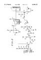
- FIG. 2is a circuit diagram of a reset circuit according to the present invention.
- FIG. 3is a block diagram of a cordless telephone incorporating the method of FIG. 1 and the reset circuit of FIG. 2.
- the present inventionencompasses a method for recovering control of a microprocessor controlled apparatus affected by a reset condition.
- the methoddetermines the cause of reset, and initializes the memory based upon the cause of the reset.
- a reset conditioncan occur either intentionally or unintentionally.
- an unintentional resetcan result from an undesirable electrostatic discharge or power glitch.
- an intentional resetcan occur by selecting a reset button on the device, by cradling the handset in a cordless telephone, or powering down the device. While it is typically desirable to start the operation of the microprocessor at the beginning of a program after an intentional reset, it may be beneficial to return to predetermined location in the program after an unintentional reset.
- a microprocessor-based cordless telephonehas volatile memory, for example a RAM, containing predetermined data, flags and control words.
- the flags and control wordsinclude variables indicating the state of the telephone and are used to maintain proper operation of the microprocessor. For example, off hook, speakerphone call, handset call or other states could be contained in the flag and control words.
- the methodgenerally evaluates predetermined data stored in the memory to determine the cause of the reset which has occurred and the required steps for initializing the memory.
- the methodfirst checks the memory for the predetermined data. If the predetermined data is not present, all RAM locations are initialized. If the predetermined data is present, only predetermined RAM locations are initialized, leaving the state information intact. With state information intact, the microprocessor will return to the proper location in the program in when power is restored. Accordingly, maintaining control after an unintentional reset, or regaining control after an intentional reset of the microprocessor is accomplished without requiring a watch-dog timer, normal microprocessor operation, or a determination of any invalid states as required in the prior art, and minimizes the disruption of the operation of the device.
- a reset of the microprocessoroccurs at a step 101
- memory locationsare first evaluated at a step 102 to determine if a predetermined pattern (stored in the RAM before the reset) is present.
- the predetermined patterncould be represented in binary, or any other format.
- the predetermined patternis represented as AA 16 and is stored in two sequential memory locations.
- Other embodimentsmay use other patterns such as 55 16 or Barker patterns.
- a previously stored control word in memorythat has not been stored solely for the purpose of checking for a predetermined pattern can be used to determine the type of reset.
- the advantage of using a previously stored control wordis that memory is not wasted by storing some other predetermined pattern.
- step 104If the predetermined pattern is present at step 103, an electrostatic discharge reset or cradled reset has most likely occurred. Accordingly, only certain portions of the RAM need to be initialized at a step 104. Since the RAM has not lost its entire contents but has only been corrupted in certain locations by an electrostatic discharge, the present state of the telephone should be preserved. Accordingly, state information (stored in the first 5 locations of the RAM) will not be initialized. If the entire contents of RAM were initialized, this state information would be lost. The loss of the state information would result in a call being disconnected if the telephone were in a call during the electrostatic discharge.
- the microprocessorreturns to the "pre-reset" state of the call.
- the methoddetermines from the uninitialized memory what state the phone was in prior to the reset and reinitializes the corrupted RAM to known good default value based on the state that existed before the reset. Therefore, if the RAM gets corrupted during a call, the method of the present invention detects the reset condition and returns the RAM to its proper state without interrupting the call.
- a predetermined patternwas initially stored in RAM for later detection, that pattern is restored at a step 106. If a control word was used as a predetermined pattern instead, this word was already restored in step 104.
- a "power-on" resethas most likely occurred.
- the memory contentswill be lost and set to FF 16 , or 00 16 , or some random pattern, upon subsequent power-up. Therefore, all locations of the RAM must be initialized at a step 107. This initialization is accomplished by the microprocessor reading the correct values from the read only memory (ROM) and storing these values in the proper RAM locations. If the initialization is not performed, the microprocessor could not execute its instructions in an orderly manner and control would be lost.
- ROMread only memory
- the main loop of the microprocessor programwill again be started at step 108. If the state information has been restored at step 104, the microprocessor will return to the proper location in memory to maintain control of the device.
- FIG. 2a circuit for generating a reset is disclosed.
- the circuitis generally external to microprocessor 199 and resets the microprocessor whenever a device is placed across charging contacts 201 and 202.
- the device placed across the charging contactsis a cordless telephone handset and the reset circuit of the present invention is contained in the base unit of the cordless telephone. That is, a "cradled reset" (referred to at step 104 of FIG. 1) will be generated whenever the cordless telephone handset is returned to its cradle for charging the handset's battery.
- a "cradled reset"(referred to at step 104 of FIG. 1) will be generated whenever the cordless telephone handset is returned to its cradle for charging the handset's battery.
- the reset circuit of the present inventionis described in reference to a cordless telephone, a typical block diagram of which illustrated in FIG. 3, other microprocessor controlled devices may use the method and reset circuit of the present invention.
- the reset circuit and method of the present inventioncan be employed in cellular telephones and trunking radios.
- the reset circuit of the present inventiongenerally includes bias resistors 203-219, transistors 221-223 and 232, capacitors 220, 230 and 231, an op amp 224 and a voltage monitor 225. These elements are configured as shown in FIG. 2 to generate a reset at microprocessor 199 when a handset is placed across contacts 201 and 202 (i.e. a cradle reset). When the handset is not in the cradle, the charge+contact 201 is pulled to A+ (12Volts (V)) via resistors 203-206, turning transistor 221 off. With transistor 221 off, there is no bias for transistor 222 and the collector of 222 is pulled to 5V via resistor 211.
- V(12Volts
- Capacitor 230is discharged to 0.1V via resistor 213, placing the non-inverting input of op amp 224 at 0.1V.
- the resistor divider including resistors 218 and 219generates 3.0V at the inverting input of op amp 224.
- Capacitor 220is coupled to the resistor divider network to reduce noise on the 3V of the resistor divider network. Because the voltage at the inverting input of the op amp exceeds the voltage at the non-inverting input, the output of the op amp is 0V.
- transistor 232With 0V at the base of transistor 232, transistor 232 is off and capacitor 231 is discharged to 0V via resistor 215. Since the 5V supply is above 4.3V, the output of voltage monitor 225 is off. Therefore, the output of voltage monitor is pulled to 5V via resistor 217 and the reset to the microprocessor is maintained at 5V.
- the 10.5Vis then applied to the base of transistor 232, turning on the transistor.
- the voltage at the base of transistor 232is limited to 5.7V by diode 233.
- capacitor 231When the transistor 232 is first turned on, capacitor 231 is discharged and the collector of transistor 232 is momentarily pulled to 0.1V and the microprocessor is put into reset. Capacitor 231 will continue to charge via resistor 216 and base to emitter path of transistor 232 to a voltage of 5V, taking the microprocessor out of reset. This low reset pulse is greater then 10 microseconds wide. After the handset is removed, the circuit will then go back to the previous state when the handset is out of the cradle.
- FIG. 3A block diagram of a typical cordless telephone using the method and reset circuit of the present invention is illustrated in FIG. 3.
- This figureshows a cordless handset 301 that communicates with a base unit 302 through an RF channel.
- Base unit 302is connected to the local telephone system.
- Base unit 302includes an antenna 303 to communicate with the handset 301.
- a transceiver 304demodulates a received signal and modulates a signal to be transmitted.
- Receive filter 305 and transmit filter 306filter received and transmitted signals to remove noise. If the telephone has a speakerphone option, a speaker 309 and a microphone 308 are connected to the speakerphone circuitry 307.
- Base unit 302is controlled by the microprocessor 199 that is coupled to reset circuit 200 (shown in detail in FIG. 2) of the present invention. Contacts of handset 301 can be coupled to contacts 201 and 202 of the base unit 302.
- the present inventionprovides the substantial benefit over the prior art in that it maintains control after an unintentional reset, or regains control after an intentional reset of the microprocessor without requiring a watch-dog timer, normal microprocessor operation, or a determination of any invalid states as required in the prior art, and minimizes the disruption of the operation of the device.
- the method of the present inventiontherefore, can tolerate an asynchronous reset in such a way that does not hinder proper operation of the telephone.
- the methodcorrects any corrupted RAM variables without requiring knowledge of what RAM, if any, is corrupted.
Landscapes
- Physics & Mathematics (AREA)
- General Physics & Mathematics (AREA)
- Engineering & Computer Science (AREA)
- Automation & Control Theory (AREA)
- Debugging And Monitoring (AREA)
- Retry When Errors Occur (AREA)
Abstract
Description
Claims (13)
Priority Applications (2)
| Application Number | Priority Date | Filing Date | Title |
|---|---|---|---|
| US08/120,144US6101421A (en) | 1993-09-10 | 1993-09-10 | Reset recovery in a microprocessor controlled device |
| CA002129581ACA2129581C (en) | 1993-09-10 | 1994-08-05 | Reset recovery in a microprocessor controlled device |
Applications Claiming Priority (1)
| Application Number | Priority Date | Filing Date | Title |
|---|---|---|---|
| US08/120,144US6101421A (en) | 1993-09-10 | 1993-09-10 | Reset recovery in a microprocessor controlled device |
Publications (1)
| Publication Number | Publication Date |
|---|---|
| US6101421Atrue US6101421A (en) | 2000-08-08 |
Family
ID=22388512
Family Applications (1)
| Application Number | Title | Priority Date | Filing Date |
|---|---|---|---|
| US08/120,144Expired - LifetimeUS6101421A (en) | 1993-09-10 | 1993-09-10 | Reset recovery in a microprocessor controlled device |
Country Status (2)
| Country | Link |
|---|---|
| US (1) | US6101421A (en) |
| CA (1) | CA2129581C (en) |
Cited By (6)
| Publication number | Priority date | Publication date | Assignee | Title |
|---|---|---|---|---|
| US20050212789A1 (en)* | 2004-03-23 | 2005-09-29 | Samsung Electro-Mechanics Co., Ltd. | Display apparatus and method of controlling the same |
| US7852701B1 (en)* | 2009-03-11 | 2010-12-14 | Xilinx, Inc. | Circuits for and methods of determining a period of time during which a device was without power |
| US8576641B1 (en) | 2010-02-26 | 2013-11-05 | Xilinx, Inc. | Method of and circuit for providing non-volatile memory in an integrated circuit |
| US8610407B2 (en) | 2003-05-27 | 2013-12-17 | Blackberry Limited | Method and apparatus for handling a charging state in a mobile electronic device |
| EP1723493B1 (en)* | 2004-02-17 | 2014-10-29 | BlackBerry Limited | Method and apparatus for handling a charging state in a mobile electronic device |
| US20160179623A1 (en)* | 2014-12-17 | 2016-06-23 | International Business Machines Corporation | Energy conscious mobile device redundancy and recovery |
Citations (9)
| Publication number | Priority date | Publication date | Assignee | Title |
|---|---|---|---|---|
| US4409635A (en)* | 1981-06-18 | 1983-10-11 | Westinghouse Electric Corp. | Electrical power system with fault tolerant control unit |
| US4521847A (en)* | 1982-09-21 | 1985-06-04 | Xerox Corporation | Control system job recovery after a malfunction |
| US4642753A (en)* | 1983-08-17 | 1987-02-10 | U.S. Philips Corporation | Domestic electrical appliance |
| US4646307A (en)* | 1983-06-22 | 1987-02-24 | Sharp Kabushiki Kaisha | Memory contents confirmation |
| US4658352A (en)* | 1983-06-02 | 1987-04-14 | Pioneer Electronic Corporation | Computer system with a back-up power supply |
| US4720812A (en)* | 1984-05-30 | 1988-01-19 | Racal-Milgo, Inc. | High speed program store with bootstrap |
| US4777626A (en)* | 1984-12-22 | 1988-10-11 | Tokyo Electric Co., Ltd. | Memory device having backup power supply |
| US4819237A (en)* | 1987-08-05 | 1989-04-04 | Digital Appliance Controls, Inc. | Method and apparatus for monitoring the validity of microprocess or volatile memory |
| US4905196A (en)* | 1984-04-26 | 1990-02-27 | Bbc Brown, Boveri & Company Ltd. | Method and storage device for saving the computer status during interrupt |
- 1993
- 1993-09-10USUS08/120,144patent/US6101421A/ennot_activeExpired - Lifetime
- 1994
- 1994-08-05CACA002129581Apatent/CA2129581C/ennot_activeExpired - Fee Related
Patent Citations (9)
| Publication number | Priority date | Publication date | Assignee | Title |
|---|---|---|---|---|
| US4409635A (en)* | 1981-06-18 | 1983-10-11 | Westinghouse Electric Corp. | Electrical power system with fault tolerant control unit |
| US4521847A (en)* | 1982-09-21 | 1985-06-04 | Xerox Corporation | Control system job recovery after a malfunction |
| US4658352A (en)* | 1983-06-02 | 1987-04-14 | Pioneer Electronic Corporation | Computer system with a back-up power supply |
| US4646307A (en)* | 1983-06-22 | 1987-02-24 | Sharp Kabushiki Kaisha | Memory contents confirmation |
| US4642753A (en)* | 1983-08-17 | 1987-02-10 | U.S. Philips Corporation | Domestic electrical appliance |
| US4905196A (en)* | 1984-04-26 | 1990-02-27 | Bbc Brown, Boveri & Company Ltd. | Method and storage device for saving the computer status during interrupt |
| US4720812A (en)* | 1984-05-30 | 1988-01-19 | Racal-Milgo, Inc. | High speed program store with bootstrap |
| US4777626A (en)* | 1984-12-22 | 1988-10-11 | Tokyo Electric Co., Ltd. | Memory device having backup power supply |
| US4819237A (en)* | 1987-08-05 | 1989-04-04 | Digital Appliance Controls, Inc. | Method and apparatus for monitoring the validity of microprocess or volatile memory |
Cited By (11)
| Publication number | Priority date | Publication date | Assignee | Title |
|---|---|---|---|---|
| US8610407B2 (en) | 2003-05-27 | 2013-12-17 | Blackberry Limited | Method and apparatus for handling a charging state in a mobile electronic device |
| EP1723493B1 (en)* | 2004-02-17 | 2014-10-29 | BlackBerry Limited | Method and apparatus for handling a charging state in a mobile electronic device |
| US20050212789A1 (en)* | 2004-03-23 | 2005-09-29 | Samsung Electro-Mechanics Co., Ltd. | Display apparatus and method of controlling the same |
| US7852701B1 (en)* | 2009-03-11 | 2010-12-14 | Xilinx, Inc. | Circuits for and methods of determining a period of time during which a device was without power |
| US8576641B1 (en) | 2010-02-26 | 2013-11-05 | Xilinx, Inc. | Method of and circuit for providing non-volatile memory in an integrated circuit |
| US20160179623A1 (en)* | 2014-12-17 | 2016-06-23 | International Business Machines Corporation | Energy conscious mobile device redundancy and recovery |
| US20160179622A1 (en)* | 2014-12-17 | 2016-06-23 | International Business Machines Corporation | Energy conscious mobile device redundancy and recovery |
| US9891997B2 (en)* | 2014-12-17 | 2018-02-13 | International Business Machines Corporation | Energy conscious mobile device redundancy and recovery |
| US9898366B2 (en)* | 2014-12-17 | 2018-02-20 | International Business Machines Corporation | Energy conscious mobile device redundancy and recovery |
| US10545827B2 (en) | 2014-12-17 | 2020-01-28 | International Business Machines Corporation | Energy conscious mobile device redundancy and recovery |
| US10545828B2 (en) | 2014-12-17 | 2020-01-28 | International Business Machines Corporation | Energy conscious mobile device redundancy and recovery |
Also Published As
| Publication number | Publication date |
|---|---|
| CA2129581A1 (en) | 1995-03-11 |
| CA2129581C (en) | 2000-09-19 |
Similar Documents
| Publication | Publication Date | Title |
|---|---|---|
| US20030109243A1 (en) | Portable electronic device with power failure recovery and operation method thereof | |
| US5812954A (en) | Mobile telephone power key lock function | |
| US8036708B2 (en) | Mobile communication terminal and mobile communication method | |
| US20020028701A1 (en) | Power switching unit of a portable telephone | |
| US4547629A (en) | Energy management circuit | |
| US5251179A (en) | Apparatus and method for extending battery life | |
| US6101421A (en) | Reset recovery in a microprocessor controlled device | |
| JPH0927836A (en) | Cordless telephone set with power failure detection function | |
| CA1300231C (en) | Automobile telephone device with battery saver | |
| US5551077A (en) | Portable telephone equipment with condition restoration | |
| US5357395A (en) | Undervoltage protection circuit, system and method of operating same | |
| US5014308A (en) | Circuit arrangement for providing power for an IC chip in a telephone subset | |
| US5831415A (en) | Electrical disconnection and automatic re-engagement of battery monitoring circuits | |
| JPS6128319Y2 (en) | ||
| US5212664A (en) | Information card with dual power detection signals to memory decoder | |
| US20020036479A1 (en) | Power circuit, power supply method, and electronic device | |
| US6144569A (en) | System and method for recovering from a power supply interruption | |
| US6778665B1 (en) | Distribution of current draw in a line powered DAA | |
| EP1093276B1 (en) | Startup procedure for international line powered DAA | |
| JP3203414B2 (en) | Receiver with interference wave prevention | |
| JP2765502B2 (en) | Backup power supply circuit | |
| JP2687772B2 (en) | Selective call receiver | |
| JP3291159B2 (en) | Portable equipment | |
| JP3233029B2 (en) | Terminal network controller | |
| JPS61273033A (en) | Method of detecting battery voltage reduction |
Legal Events
| Date | Code | Title | Description |
|---|---|---|---|
| AS | Assignment | Owner name:MOTOROLA, INC., ILLINOIS Free format text:ASSIGNMENT OF ASSIGNORS INTEREST;ASSIGNORS:GOEDKEN, JAMES FRANCIS;HAMMON, RICHARD LEE;REEL/FRAME:006825/0407 Effective date:19931105 | |
| STCF | Information on status: patent grant | Free format text:PATENTED CASE | |
| FPAY | Fee payment | Year of fee payment:4 | |
| FPAY | Fee payment | Year of fee payment:8 | |
| AS | Assignment | Owner name:MOTOROLA MOBILITY, INC, ILLINOIS Free format text:ASSIGNMENT OF ASSIGNORS INTEREST;ASSIGNOR:MOTOROLA, INC;REEL/FRAME:025673/0558 Effective date:20100731 | |
| FPAY | Fee payment | Year of fee payment:12 | |
| AS | Assignment | Owner name:MOTOROLA MOBILITY LLC, ILLINOIS Free format text:CHANGE OF NAME;ASSIGNOR:MOTOROLA MOBILITY, INC.;REEL/FRAME:029216/0282 Effective date:20120622 | |
| AS | Assignment | Owner name:GOOGLE TECHNOLOGY HOLDINGS LLC, CALIFORNIA Free format text:ASSIGNMENT OF ASSIGNORS INTEREST;ASSIGNOR:MOTOROLA MOBILITY LLC;REEL/FRAME:034303/0001 Effective date:20141028 |