US6101269A - Apparatus and method for rapid 3D image parametrization - Google Patents
Apparatus and method for rapid 3D image parametrizationDownload PDFInfo
- Publication number
- US6101269A US6101269AUS08/994,803US99480397AUS6101269AUS 6101269 AUS6101269 AUS 6101269AUS 99480397 AUS99480397 AUS 99480397AUS 6101269 AUS6101269 AUS 6101269A
- Authority
- US
- United States
- Prior art keywords
- dimensional
- speckle pattern
- digital images
- speckle
- set forth
- Prior art date
- Legal status (The legal status is an assumption and is not a legal conclusion. Google has not performed a legal analysis and makes no representation as to the accuracy of the status listed.)
- Expired - Lifetime
Links
Images
Classifications
- G—PHYSICS
- G01—MEASURING; TESTING
- G01B—MEASURING LENGTH, THICKNESS OR SIMILAR LINEAR DIMENSIONS; MEASURING ANGLES; MEASURING AREAS; MEASURING IRREGULARITIES OF SURFACES OR CONTOURS
- G01B11/00—Measuring arrangements characterised by the use of optical techniques
- G01B11/24—Measuring arrangements characterised by the use of optical techniques for measuring contours or curvatures
- G01B11/25—Measuring arrangements characterised by the use of optical techniques for measuring contours or curvatures by projecting a pattern, e.g. one or more lines, moiré fringes on the object
- G01B11/2545—Measuring arrangements characterised by the use of optical techniques for measuring contours or curvatures by projecting a pattern, e.g. one or more lines, moiré fringes on the object with one projection direction and several detection directions, e.g. stereo
Definitions
- This inventionrelates to the measurement and modeling of a three dimensional surface. More particularly, this invention relates to measuring and modeling a three dimensional surface by projecting a speckle pattern upon the three dimensional surface, imaging the speckle pattern with a plurality of cameras to obtain a plurality of two dimensional digital images, and obtaining from the plurality of two dimensional digital images a three dimensional digital image and a model parameter set representing the three dimensional illuminated surface.
- Speckle techniquesboth photographic and interferometric, are known to produce images of surfaces containing a rich set of spatial frequencies thereby providing spatial information on a wide range of spatial scales.
- a survey of speckle techniquesis provided in Jones, Robert, Holographic and speckle interferometry: a discussion of the theory, practice, and application of the techniques, 2nd ed., Cambridge University Press (1989), which is herein incorporated by reference.
- a preferred embodiment of the present inventionprovides a method for measuring and modeling a three dimensional surface.
- This methodhas the steps of: (i) illuminating the three dimensional surface with a speckle pattern; (ii) imaging the speckle pattern to obtain a plurality of two dimensional digital images; and (iii) processing the plurality of two dimensional digital images to obtain a three dimensional digital characterization of the illuminated three dimensional surface.
- a further embodimentincludes the step of modeling the illuminated surface, based upon the plurality of two dimensional digital images, to obtain a parameter set characterizing the illuminated surface.
- the embodimentincludes performing steps (i)-(iii) as outlined above more than once to provide an ensemble of speckle patterns and an ensemble of two dimensional digital images, wherein the ensemble of speckle patterns contains at least two distinct speckle patterns.
- the methodalso has the step of modeling the illuminated surface to obtain a parameter set characterizing the illuminated surface, wherein the modeling is based upon the ensemble of two dimensional digital images.
- an apparatus for rapid three dimensional image parametrization of a three dimensional surfacehas a speckle pattern generator for providing a speckle pattern upon the three dimensional surface; a plurality of cameras for imaging the speckle pattern to provide a plurality of two dimensional digital images; and a processor in communication with the plurality of cameras for processing the plurality of two dimensional digital images to obtain a three dimensional digital characterization of the three dimensional surface.
- the processormay further provides a parameter set characterizing the three dimensional surface.
- the speckle pattern generatormay have a source of optical radiation coupled through an optical fiber, as well as a speckle pattern shifter for varying the speckle pattern projected upon the three dimensional surface as a function of time.
- the speckle pattern shiftermay be a mechanical strain inducer for applying strain to the optical fiber, and the mechanical strain inducer may be a piezoelectric element.
- Yet another embodiment of the present inventionis an apparatus for rapid three dimensional image parametrization of a three dimensional surface, where the apparatus comprises a speckle pattern generator for providing a speckle pattern upon the three dimensional surface; a plurality of cameras for imaging the speckle pattern to provide a plurality of two dimensional digital images; a memory in communication with the plurality of cameras for storing the plurality of two dimensional digital images; and a processor in communication with the memory for processing the plurality of two dimensional digital images to obtain a three dimensional digital characterization of the three dimensional surface.
- a speckle pattern generatorfor providing a speckle pattern upon the three dimensional surface
- a plurality of camerasfor imaging the speckle pattern to provide a plurality of two dimensional digital images
- a memoryin communication with the plurality of cameras for storing the plurality of two dimensional digital images
- a processorin communication with the memory for processing the plurality of two dimensional digital images to obtain a three dimensional digital characterization of the three dimensional surface.
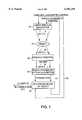
- FIG. 1illustrates a flow diagram for a preferred embodiment of the invention.
- FIG. 1An embodiment of a method for measuring and modeling a three dimensional surface of an object is illustrated in FIG. 1.
- An object 10is illuminated by a laser speckle generator 20.
- the techniques of the present inventionare broadly applicable to various optical inspection modalities known in the art, and the application of these techniques to any of such modalities is considered within the scope of the invention and of the appended claims.
- laser speckle generator 20is a laser coupled to one end of an optical fiber, using optical coupling techniques known to persons of ordinary skill in the art.
- the end of the optical fiber distal to the laseris used to illuminate the object.
- the laser speckle generatorprojects a speckle pattern upon object 10.
- a speckle patternis a pattern of illumination in which the intensity profile of the illumination appears as a realization of a random illumination pattern.
- a laser coupled to an inexpensive, low quality optical fibermay provide a speckle pattern, and it is this combination which serves as a speckle generator in a preferred embodiment.
- the specklemay be diffraction limited thereby providing a random pattern including the highest spatial frequencies attainable.
- a mechanical strainmay be applied to the optical fiber so that an entire ensemble of uncorrelated speckle patterns can be generated by changing the mechanical strain. This can be accomplished by wrapping the optical fiber around a piezoelectric material, so that a voltage applied to the piezoelectric material causes it to apply a mechanical stress to the optical fiber.
- a plurality of cameras 30is used to image the speckle patterns illuminated on object 10.
- cameras 30provide digital images. Due to parallax, the images obtained from cameras 30 will be different from each other. From the differences in the digital images obtained from cameras 30, and from knowledge of the relative positions of the cameras to each other, three dimensional coordinates describing the three dimensional surface of object 10 may be obtained for each speckle illumination. Use is made of the random nature of the speckle illumination pattern in determining the differences in the digital images due to parallax. If the speckle pattern is sufficiently random, then small portions of the speckle pattern will be sufficiently different from other small portions of the speckle pattern, and determining the relative shifts of the digital images will be facilitated by making comparisons among these uniquely identifiable small portions.
- Parameters of a modelmay be chosen to fit the digital images obtained from cameras 30 according to a model parameter fitting algorithm, as indicated in step 40 of FIG. 1.
- Finite element modeling of a surfaceis the subject of P. Charette et al., "Large deformation mechanical testing of biological membranes using speckle interferometry in transmission. II. Finite element modeling," Applied Optics, vol. 36(10), pp. 2246-51 (1997), which is incorporated herein by reference.
- the parametersmay be obtained by a least squares fit using the finite element method in which the basis functions are cubic-Hermite functions.
- the parameters obtained from model parameter fitting step 40are used in 50 to obtain a model of the three dimensional surface of object 10. These parameters may be used to display the three dimensional surface of object 10, or they may be used to fabricate or synthesize new three dimensional surfaces which characterize the three dimensional surface of object 10.
- the illumination and imaging processmay be repeated a number of times with or without changing the speckle pattern.
- the surface of object 10may be changing as a function of time, in which case the process must be repeated to obtain parameter sets indexed by time. This is indicated by temporal bandwidth control line 60.
- the spatial bandwidth control line 70There is also the spatial frequency aspects of the three dimensional surface which must be properly captured. This is indicated by the spatial bandwidth control line 70, in which object 10 is repeatedly illuminated with different speckle patterns generated by laser speckle generator 20 for each illumination step.
- speckle patternswhich are statistically uncorrelated from each other, it is possible to capture features of the surface of object 10 that might otherwise be missed if the same speckle pattern was used throughout the measurement and modeling process.
- Statistical averagingmay be employed over the ensemble of digital images obtained by illuminating object 10 with different speckle patterns, so that a single parameter set is obtained in which the spatial features of the surface of object 10 are properly captured.
Landscapes
- Engineering & Computer Science (AREA)
- Computer Vision & Pattern Recognition (AREA)
- Physics & Mathematics (AREA)
- General Physics & Mathematics (AREA)
- Length Measuring Devices By Optical Means (AREA)
Abstract
Description
Claims (12)
Priority Applications (1)
| Application Number | Priority Date | Filing Date | Title |
|---|---|---|---|
| US08/994,803US6101269A (en) | 1997-12-19 | 1997-12-19 | Apparatus and method for rapid 3D image parametrization |
Applications Claiming Priority (1)
| Application Number | Priority Date | Filing Date | Title |
|---|---|---|---|
| US08/994,803US6101269A (en) | 1997-12-19 | 1997-12-19 | Apparatus and method for rapid 3D image parametrization |
Publications (1)
| Publication Number | Publication Date |
|---|---|
| US6101269Atrue US6101269A (en) | 2000-08-08 |
Family
ID=25541070
Family Applications (1)
| Application Number | Title | Priority Date | Filing Date |
|---|---|---|---|
| US08/994,803Expired - LifetimeUS6101269A (en) | 1997-12-19 | 1997-12-19 | Apparatus and method for rapid 3D image parametrization |
Country Status (1)
| Country | Link |
|---|---|
| US (1) | US6101269A (en) |
Cited By (39)
| Publication number | Priority date | Publication date | Assignee | Title |
|---|---|---|---|---|
| US20040061680A1 (en)* | 2002-07-10 | 2004-04-01 | John Taboada | Method and apparatus for computer control |
| US20060132709A1 (en)* | 2004-12-17 | 2006-06-22 | The Regents Of The University Of California | High-resolution ophthalmic imaging system |
| US20070216894A1 (en)* | 2006-02-27 | 2007-09-20 | Javier Garcia | Range mapping using speckle decorrelation |
| US20080106746A1 (en)* | 2005-10-11 | 2008-05-08 | Alexander Shpunt | Depth-varying light fields for three dimensional sensing |
| US20080117416A1 (en)* | 2006-10-27 | 2008-05-22 | Hunter Ian W | Use of coherent raman techniques for medical diagnostic and therapeutic purposes, and calibration techniques for same |
| US20080240502A1 (en)* | 2007-04-02 | 2008-10-02 | Barak Freedman | Depth mapping using projected patterns |
| US20090096783A1 (en)* | 2005-10-11 | 2009-04-16 | Alexander Shpunt | Three-dimensional sensing using speckle patterns |
| US20100007717A1 (en)* | 2008-07-09 | 2010-01-14 | Prime Sense Ltd | Integrated processor for 3d mapping |
| US20100020078A1 (en)* | 2007-01-21 | 2010-01-28 | Prime Sense Ltd | Depth mapping using multi-beam illumination |
| US20100118123A1 (en)* | 2007-04-02 | 2010-05-13 | Prime Sense Ltd | Depth mapping using projected patterns |
| US20100177164A1 (en)* | 2005-10-11 | 2010-07-15 | Zeev Zalevsky | Method and System for Object Reconstruction |
| US20100201811A1 (en)* | 2009-02-12 | 2010-08-12 | Prime Sense Ltd. | Depth ranging with moire patterns |
| US20100225746A1 (en)* | 2009-03-05 | 2010-09-09 | Prime Sense Ltd | Reference image techniques for three-dimensional sensing |
| US20100265316A1 (en)* | 2009-04-16 | 2010-10-21 | Primesense Ltd. | Three-dimensional mapping and imaging |
| US20100290698A1 (en)* | 2007-06-19 | 2010-11-18 | Prime Sense Ltd | Distance-Varying Illumination and Imaging Techniques for Depth Mapping |
| US20110025827A1 (en)* | 2009-07-30 | 2011-02-03 | Primesense Ltd. | Depth Mapping Based on Pattern Matching and Stereoscopic Information |
| US20110096182A1 (en)* | 2009-10-25 | 2011-04-28 | Prime Sense Ltd | Error Compensation in Three-Dimensional Mapping |
| US20110134114A1 (en)* | 2009-12-06 | 2011-06-09 | Primesense Ltd. | Depth-based gain control |
| US20110154201A1 (en)* | 2009-12-22 | 2011-06-23 | Akira Nakanishi | Video Reproducing Apparatus and Video Reproducing Method |
| US20110158508A1 (en)* | 2005-10-11 | 2011-06-30 | Primesense Ltd. | Depth-varying light fields for three dimensional sensing |
| US20110187878A1 (en)* | 2010-02-02 | 2011-08-04 | Primesense Ltd. | Synchronization of projected illumination with rolling shutter of image sensor |
| US20110211044A1 (en)* | 2010-03-01 | 2011-09-01 | Primesense Ltd. | Non-Uniform Spatial Resource Allocation for Depth Mapping |
| US8599484B2 (en) | 2010-08-10 | 2013-12-03 | Asahi Glass Company, Limited | Diffractive optical element and measuring device |
| US8971572B1 (en) | 2011-08-12 | 2015-03-03 | The Research Foundation For The State University Of New York | Hand pointing estimation for human computer interaction |
| US8995057B2 (en) | 2010-11-02 | 2015-03-31 | Asahi Glass Company, Limited | Diffractive optical element and measurement instrument |
| US9030528B2 (en) | 2011-04-04 | 2015-05-12 | Apple Inc. | Multi-zone imaging sensor and lens array |
| US9066087B2 (en) | 2010-11-19 | 2015-06-23 | Apple Inc. | Depth mapping using time-coded illumination |
| US9098931B2 (en) | 2010-08-11 | 2015-08-04 | Apple Inc. | Scanning projectors and image capture modules for 3D mapping |
| US9131136B2 (en) | 2010-12-06 | 2015-09-08 | Apple Inc. | Lens arrays for pattern projection and imaging |
| US9157790B2 (en) | 2012-02-15 | 2015-10-13 | Apple Inc. | Integrated optoelectronic modules with transmitter, receiver and beam-combining optics for aligning a beam axis with a collection axis |
| CN105203044A (en)* | 2015-05-27 | 2015-12-30 | 珠海真幻科技有限公司 | Method and system for stereoscopic vision three-dimensional measurement taking computing laser speckles as texture |
| US9330324B2 (en) | 2005-10-11 | 2016-05-03 | Apple Inc. | Error compensation in three-dimensional mapping |
| WO2016118310A1 (en)* | 2015-01-21 | 2016-07-28 | Microsoft Technology Licensing, Llc | Multiple exposure structured light pattern |
| US9477018B2 (en) | 2010-08-06 | 2016-10-25 | Asahi Glass Company, Limited | Diffractive optical element and measurement device |
| CN106643492A (en)* | 2016-11-18 | 2017-05-10 | 中国民航大学 | Aeroengine damaged blade three-dimensional digital speckle moulding method |
| US9927523B2 (en) | 2013-12-16 | 2018-03-27 | Samsung Electronics Co., Ltd. | Event filtering device and motion recognition device thereof |
| WO2020012126A1 (en)* | 2018-07-12 | 2020-01-16 | Safran | Method and device for contactless measurement of the 3d profile of an object |
| US10547830B2 (en) | 2015-11-16 | 2020-01-28 | Samsung Electronics Co., Ltd | Apparatus for and method of illumination control for acquiring image information and depth information simultaneously |
| FR3107117A1 (en)* | 2020-02-10 | 2021-08-13 | Saint-Gobain Glass France | Method for measuring the geometry of a glazing |
Citations (7)
| Publication number | Priority date | Publication date | Assignee | Title |
|---|---|---|---|---|
| US4148587A (en)* | 1977-10-03 | 1979-04-10 | The Boeing Company | Laser gauge for measuring changes in the surface contour of a moving part |
| US4657394A (en)* | 1984-09-14 | 1987-04-14 | New York Institute Of Technology | Apparatus and method for obtaining three dimensional surface contours |
| US4746211A (en)* | 1984-01-18 | 1988-05-24 | Gesellschaft fur Strahlen- und Unweltforschung mbH | Real time velocity determination |
| US5548418A (en)* | 1994-01-14 | 1996-08-20 | Dcs Corporation | Holographic structured light generator |
| WO1996025764A1 (en)* | 1995-02-16 | 1996-08-22 | Environmental Research Institute Of Michigan | System and method for three-dimensional imaging of opaque objects |
| JPH0914914A (en)* | 1994-06-06 | 1997-01-17 | Kishimoto Sangyo Kk | Laser light projection method and apparatus therefor in device measuring for moving value by laser speckle pattern |
| US5870490A (en)* | 1993-04-16 | 1999-02-09 | Nippon Telegraph And Telephone Corporation | Apparatus for extracting pattern features |
- 1997
- 1997-12-19USUS08/994,803patent/US6101269A/ennot_activeExpired - Lifetime
Patent Citations (7)
| Publication number | Priority date | Publication date | Assignee | Title |
|---|---|---|---|---|
| US4148587A (en)* | 1977-10-03 | 1979-04-10 | The Boeing Company | Laser gauge for measuring changes in the surface contour of a moving part |
| US4746211A (en)* | 1984-01-18 | 1988-05-24 | Gesellschaft fur Strahlen- und Unweltforschung mbH | Real time velocity determination |
| US4657394A (en)* | 1984-09-14 | 1987-04-14 | New York Institute Of Technology | Apparatus and method for obtaining three dimensional surface contours |
| US5870490A (en)* | 1993-04-16 | 1999-02-09 | Nippon Telegraph And Telephone Corporation | Apparatus for extracting pattern features |
| US5548418A (en)* | 1994-01-14 | 1996-08-20 | Dcs Corporation | Holographic structured light generator |
| JPH0914914A (en)* | 1994-06-06 | 1997-01-17 | Kishimoto Sangyo Kk | Laser light projection method and apparatus therefor in device measuring for moving value by laser speckle pattern |
| WO1996025764A1 (en)* | 1995-02-16 | 1996-08-22 | Environmental Research Institute Of Michigan | System and method for three-dimensional imaging of opaque objects |
Non-Patent Citations (9)
| Title |
|---|
| Alsberg et al. Three Dimensional Flow Visualization via Reconstruction from Successive Two Dimensional Vector Velocity Maps. Engineering in Medicine and Biology Society, 1994. Engineering Advances: New Opportunities for Biomedical Engineers., Proceedi, Jun. 1994.* |
| Alsberg et al. Three-Dimensional Flow Visualization via Reconstruction from Successive Two-Dimensional Vector Velocity Maps. Engineering in Medicine and Biology Society, 1994. Engineering Advances: New Opportunities for Biomedical Engineers., Proceedi, Jun. 1994. |
| Lulli A., et al., "Contrast variations in white-light speckle Interferometry with application to 3D profilometry," Optics Communications, vol. 124, No. 5/06, Mar. 15, 1996, pp. 550-557, XP000583811. |
| Lulli A., et al., Contrast variations in white light speckle Interferometry with application to 3D profilometry, Optics Communications, vol. 124, No. 5/06, Mar. 15, 1996, pp. 550 557, XP000583811.* |
| Patent Abstracts of Japan, vol. 097, No. 005, May 30, 1997 & JP 09 014914 A (Kishimoto Sangyo KK), Jan. 17, 1997.* |
| Pryputniewicz, Ryszard J., "Speckle Metrology Techniques and Their Applications," International Conference On Speckle, Henri H. Arsenault, Editor, Proc. SPIE 556, pp. 90-98 (1985). |
| Pryputniewicz, Ryszard J., Speckle Metrology Techniques and Their Applications, International Conference On Speckle , Henri H. Arsenault, Editor, Proc. SPIE 556, pp. 90 98 (1985).* |
| SPIE Proceedings vol. 2909. Three Dimensional Imaging And Laser Based Systems for Metrology and Inspection II Editor(s): Kevin G. Harding, Industrial Technology Institute, Ann Arbor, MI, USA; Donald J. Svetkoff, View Engineering, Inc., Ann Arbor, MI, USA. Abstract only.* |
| SPIE Proceedings vol. 2909. Three-Dimensional Imaging And Laser-Based Systems for Metrology and Inspection II Editor(s): Kevin G. Harding, Industrial Technology Institute, Ann Arbor, MI, USA; Donald J. Svetkoff, View Engineering, Inc., Ann Arbor, MI, USA. Abstract only. |
Cited By (70)
| Publication number | Priority date | Publication date | Assignee | Title |
|---|---|---|---|---|
| US20040061680A1 (en)* | 2002-07-10 | 2004-04-01 | John Taboada | Method and apparatus for computer control |
| US7303280B2 (en) | 2004-12-17 | 2007-12-04 | The Regents Of The University Of California | High-resolution ophthalmic imaging system |
| US20060132709A1 (en)* | 2004-12-17 | 2006-06-22 | The Regents Of The University Of California | High-resolution ophthalmic imaging system |
| US20090096783A1 (en)* | 2005-10-11 | 2009-04-16 | Alexander Shpunt | Three-dimensional sensing using speckle patterns |
| US20080106746A1 (en)* | 2005-10-11 | 2008-05-08 | Alexander Shpunt | Depth-varying light fields for three dimensional sensing |
| US8400494B2 (en) | 2005-10-11 | 2013-03-19 | Primesense Ltd. | Method and system for object reconstruction |
| US8390821B2 (en) | 2005-10-11 | 2013-03-05 | Primesense Ltd. | Three-dimensional sensing using speckle patterns |
| US8374397B2 (en) | 2005-10-11 | 2013-02-12 | Primesense Ltd | Depth-varying light fields for three dimensional sensing |
| US8050461B2 (en) | 2005-10-11 | 2011-11-01 | Primesense Ltd. | Depth-varying light fields for three dimensional sensing |
| US20100177164A1 (en)* | 2005-10-11 | 2010-07-15 | Zeev Zalevsky | Method and System for Object Reconstruction |
| US20110158508A1 (en)* | 2005-10-11 | 2011-06-30 | Primesense Ltd. | Depth-varying light fields for three dimensional sensing |
| US9066084B2 (en) | 2005-10-11 | 2015-06-23 | Apple Inc. | Method and system for object reconstruction |
| US9330324B2 (en) | 2005-10-11 | 2016-05-03 | Apple Inc. | Error compensation in three-dimensional mapping |
| US7433024B2 (en)* | 2006-02-27 | 2008-10-07 | Prime Sense Ltd. | Range mapping using speckle decorrelation |
| US20070216894A1 (en)* | 2006-02-27 | 2007-09-20 | Javier Garcia | Range mapping using speckle decorrelation |
| CN101496032B (en)* | 2006-02-27 | 2011-08-17 | 普莱姆传感有限公司 | Range mapping using speckle decorrelation |
| EP1994503A4 (en)* | 2006-03-14 | 2014-02-26 | Prime Sense Ltd | Depth-varying light fields for three dimensional sensing |
| US20080117416A1 (en)* | 2006-10-27 | 2008-05-22 | Hunter Ian W | Use of coherent raman techniques for medical diagnostic and therapeutic purposes, and calibration techniques for same |
| US20100020078A1 (en)* | 2007-01-21 | 2010-01-28 | Prime Sense Ltd | Depth mapping using multi-beam illumination |
| US8350847B2 (en) | 2007-01-21 | 2013-01-08 | Primesense Ltd | Depth mapping using multi-beam illumination |
| US20080240502A1 (en)* | 2007-04-02 | 2008-10-02 | Barak Freedman | Depth mapping using projected patterns |
| US8493496B2 (en) | 2007-04-02 | 2013-07-23 | Primesense Ltd. | Depth mapping using projected patterns |
| US20100118123A1 (en)* | 2007-04-02 | 2010-05-13 | Prime Sense Ltd | Depth mapping using projected patterns |
| US8150142B2 (en) | 2007-04-02 | 2012-04-03 | Prime Sense Ltd. | Depth mapping using projected patterns |
| US8494252B2 (en) | 2007-06-19 | 2013-07-23 | Primesense Ltd. | Depth mapping using optical elements having non-uniform focal characteristics |
| US20100290698A1 (en)* | 2007-06-19 | 2010-11-18 | Prime Sense Ltd | Distance-Varying Illumination and Imaging Techniques for Depth Mapping |
| US8456517B2 (en) | 2008-07-09 | 2013-06-04 | Primesense Ltd. | Integrated processor for 3D mapping |
| US20100007717A1 (en)* | 2008-07-09 | 2010-01-14 | Prime Sense Ltd | Integrated processor for 3d mapping |
| US8462207B2 (en) | 2009-02-12 | 2013-06-11 | Primesense Ltd. | Depth ranging with Moiré patterns |
| US20100201811A1 (en)* | 2009-02-12 | 2010-08-12 | Prime Sense Ltd. | Depth ranging with moire patterns |
| US20100225746A1 (en)* | 2009-03-05 | 2010-09-09 | Prime Sense Ltd | Reference image techniques for three-dimensional sensing |
| US8786682B2 (en) | 2009-03-05 | 2014-07-22 | Primesense Ltd. | Reference image techniques for three-dimensional sensing |
| US20100265316A1 (en)* | 2009-04-16 | 2010-10-21 | Primesense Ltd. | Three-dimensional mapping and imaging |
| US8717417B2 (en) | 2009-04-16 | 2014-05-06 | Primesense Ltd. | Three-dimensional mapping and imaging |
| US20110025827A1 (en)* | 2009-07-30 | 2011-02-03 | Primesense Ltd. | Depth Mapping Based on Pattern Matching and Stereoscopic Information |
| US9582889B2 (en) | 2009-07-30 | 2017-02-28 | Apple Inc. | Depth mapping based on pattern matching and stereoscopic information |
| US20110096182A1 (en)* | 2009-10-25 | 2011-04-28 | Prime Sense Ltd | Error Compensation in Three-Dimensional Mapping |
| US8830227B2 (en) | 2009-12-06 | 2014-09-09 | Primesense Ltd. | Depth-based gain control |
| US20110134114A1 (en)* | 2009-12-06 | 2011-06-09 | Primesense Ltd. | Depth-based gain control |
| US20110154201A1 (en)* | 2009-12-22 | 2011-06-23 | Akira Nakanishi | Video Reproducing Apparatus and Video Reproducing Method |
| US8413053B2 (en)* | 2009-12-22 | 2013-04-02 | Kabushiki Kaisha Toshiba | Video reproducing apparatus and video reproducing method |
| US20110187878A1 (en)* | 2010-02-02 | 2011-08-04 | Primesense Ltd. | Synchronization of projected illumination with rolling shutter of image sensor |
| US20110211044A1 (en)* | 2010-03-01 | 2011-09-01 | Primesense Ltd. | Non-Uniform Spatial Resource Allocation for Depth Mapping |
| US8982182B2 (en) | 2010-03-01 | 2015-03-17 | Apple Inc. | Non-uniform spatial resource allocation for depth mapping |
| US9477018B2 (en) | 2010-08-06 | 2016-10-25 | Asahi Glass Company, Limited | Diffractive optical element and measurement device |
| US8599484B2 (en) | 2010-08-10 | 2013-12-03 | Asahi Glass Company, Limited | Diffractive optical element and measuring device |
| US9098931B2 (en) | 2010-08-11 | 2015-08-04 | Apple Inc. | Scanning projectors and image capture modules for 3D mapping |
| US8995057B2 (en) | 2010-11-02 | 2015-03-31 | Asahi Glass Company, Limited | Diffractive optical element and measurement instrument |
| US9066087B2 (en) | 2010-11-19 | 2015-06-23 | Apple Inc. | Depth mapping using time-coded illumination |
| US9131136B2 (en) | 2010-12-06 | 2015-09-08 | Apple Inc. | Lens arrays for pattern projection and imaging |
| US9167138B2 (en) | 2010-12-06 | 2015-10-20 | Apple Inc. | Pattern projection and imaging using lens arrays |
| US9030528B2 (en) | 2011-04-04 | 2015-05-12 | Apple Inc. | Multi-zone imaging sensor and lens array |
| US8971572B1 (en) | 2011-08-12 | 2015-03-03 | The Research Foundation For The State University Of New York | Hand pointing estimation for human computer interaction |
| US9372546B2 (en) | 2011-08-12 | 2016-06-21 | The Research Foundation For The State University Of New York | Hand pointing estimation for human computer interaction |
| US9651417B2 (en) | 2012-02-15 | 2017-05-16 | Apple Inc. | Scanning depth engine |
| US9157790B2 (en) | 2012-02-15 | 2015-10-13 | Apple Inc. | Integrated optoelectronic modules with transmitter, receiver and beam-combining optics for aligning a beam axis with a collection axis |
| US9927523B2 (en) | 2013-12-16 | 2018-03-27 | Samsung Electronics Co., Ltd. | Event filtering device and motion recognition device thereof |
| WO2016118310A1 (en)* | 2015-01-21 | 2016-07-28 | Microsoft Technology Licensing, Llc | Multiple exposure structured light pattern |
| US9958758B2 (en) | 2015-01-21 | 2018-05-01 | Microsoft Technology Licensing, Llc | Multiple exposure structured light pattern |
| WO2016188068A1 (en)* | 2015-05-27 | 2016-12-01 | 珠海真幻科技有限公司 | Method and system for stereoscopic vision three-dimensional measurement taking computing laser speckles as texture |
| CN105203044A (en)* | 2015-05-27 | 2015-12-30 | 珠海真幻科技有限公司 | Method and system for stereoscopic vision three-dimensional measurement taking computing laser speckles as texture |
| US10547830B2 (en) | 2015-11-16 | 2020-01-28 | Samsung Electronics Co., Ltd | Apparatus for and method of illumination control for acquiring image information and depth information simultaneously |
| US11153551B2 (en) | 2015-11-16 | 2021-10-19 | Samsung Electronics Co., Ltd | Apparatus for and method of illumination control for acquiring image information and depth information simultaneously |
| CN106643492A (en)* | 2016-11-18 | 2017-05-10 | 中国民航大学 | Aeroengine damaged blade three-dimensional digital speckle moulding method |
| CN106643492B (en)* | 2016-11-18 | 2018-11-02 | 中国民航大学 | A kind of aero-engine damaged blade 3-dimensional digital speckle formative method |
| FR3083857A1 (en)* | 2018-07-12 | 2020-01-17 | Safran | MEASUREMENT OF THE 3D PROFILE OF AN OBJECT |
| WO2020012126A1 (en)* | 2018-07-12 | 2020-01-16 | Safran | Method and device for contactless measurement of the 3d profile of an object |
| FR3107117A1 (en)* | 2020-02-10 | 2021-08-13 | Saint-Gobain Glass France | Method for measuring the geometry of a glazing |
| WO2021160618A1 (en)* | 2020-02-10 | 2021-08-19 | Saint-Gobain Glass France | Method for measuring the geometry of a glass panel |
| US12392728B2 (en) | 2020-02-10 | 2025-08-19 | Saint-Gobain Glass France | Method for measuring the geometry of a glazing by projection of a random light pattern |
Similar Documents
| Publication | Publication Date | Title |
|---|---|---|
| US6101269A (en) | Apparatus and method for rapid 3D image parametrization | |
| CA2275411A1 (en) | Apparatus and method for rapid 3d image parametrization | |
| KR100858521B1 (en) | Method for manufacturing a product using inspection | |
| JP5214883B2 (en) | Method and apparatus for three-dimensional spectrally encoded imaging | |
| Zhang et al. | High dynamic range scanning technique | |
| US7079666B2 (en) | System for simultaneous projections of multiple phase-shifted patterns for the three-dimensional inspection of an object | |
| US5967979A (en) | Method and apparatus for photogrammetric assessment of biological tissue | |
| CN104783757B (en) | Focus on scanning device | |
| JPH10508107A (en) | Apparatus and method for determining a three-dimensional shape of an object using relative blur in an image due to active illumination and defocus | |
| CN102334006A (en) | Intensity and color display for 3D metrology systems | |
| US11153696B2 (en) | Ear canal modeling using pattern projection | |
| JP2001523827A (en) | Three-dimensional imaging by triangulation using dual-wavelength light | |
| JPH09218022A (en) | Method for determining the contour of the diffusion surface of the work | |
| Escamilla et al. | Three-dimensional surface measurement based on the projected defocused pattern technique using imaging fiber optics | |
| Dirckx et al. | Optoelectronic moiré projector for real-time shape and deformation studies of the tympanic membrane | |
| D'Apuzzo | Automated photogrammetric measurement of human faces | |
| Muyshondt et al. | A calibrated 3D dual-barrel otoendoscope based on fringe-projection profilometry | |
| Zhang et al. | High dynamic range scanning technique | |
| CA2955391A1 (en) | Method and apparatus for measuring optical systems and surfaces with optical ray metrology | |
| JP2020506384A (en) | Method for evaluating the measurement quality of a wavefront and an apparatus for implementing such a method | |
| Dirckx et al. | Video moiré topography for in-vitro studies of the eardrum | |
| CN112325799A (en) | High-precision three-dimensional face measurement method based on near-infrared light projection | |
| Shakher et al. | Image processing and analysis of digital speckle pattern interferometric images for monitoring/surface vibration/tilt | |
| CN115711592B (en) | Object shape measurement method based on single-pixel imaging binocular deflectometry | |
| US20250271327A1 (en) | Method and system for characterizing an optical lens for correcting optical aberrations introduced by said optical lens in an image |
Legal Events
| Date | Code | Title | Description |
|---|---|---|---|
| AS | Assignment | Owner name:PACIFIC TITLE AND MIRAGE, INC., CALIFORNIA Free format text:ASSIGNMENT OF ASSIGNORS INTEREST;ASSIGNORS:HUNTER, IAN W.;CHARETTE, PAUL G.;REEL/FRAME:009433/0202 Effective date:19980813 | |
| AS | Assignment | Owner name:LIFEF/X NETWORKS, INC., CALIFORNIA Free format text:MERGER;ASSIGNOR:PACIFIC TITLE/MIRAGE, INC.;REEL/FRAME:010539/0803 Effective date:19991206 | |
| AS | Assignment | Owner name:LIFEF/X NETWORKS, INC., MASSACHUSETTS Free format text:CONFIRMATORY LICENSE;ASSIGNOR:MIRAGE TECHNOLOGIES LIMITED PARTNERSHIP, INC.;REEL/FRAME:010719/0797 Effective date:20000225 | |
| STCF | Information on status: patent grant | Free format text:PATENTED CASE | |
| CC | Certificate of correction | ||
| FEPP | Fee payment procedure | Free format text:PAT HOLDER NO LONGER CLAIMS SMALL ENTITY STATUS, ENTITY STATUS SET TO UNDISCOUNTED (ORIGINAL EVENT CODE: STOL); ENTITY STATUS OF PATENT OWNER: LARGE ENTITY | |
| FEPP | Fee payment procedure | Free format text:PAYOR NUMBER ASSIGNED (ORIGINAL EVENT CODE: ASPN); ENTITY STATUS OF PATENT OWNER: LARGE ENTITY | |
| FPAY | Fee payment | Year of fee payment:4 | |
| AS | Assignment | Owner name:AUCKLAND UNISERVICES LIMITED, NEW ZEALAND Free format text:ASSIGNMENT OF ASSIGNORS INTEREST;ASSIGNOR:LIFEF/X TECHNOLOGIES, INC.;REEL/FRAME:016397/0736 Effective date:20050506 Owner name:LIFEF/X TECHNOLOGIES, INC., MASSACHUSETTS Free format text:ASSIGNMENT OF ASSIGNORS INTEREST;ASSIGNORS:LIFEF/X, INC.;LIFEF/X NETWORKS, INC.;REEL/FRAME:016397/0715 Effective date:20030715 | |
| FEPP | Fee payment procedure | Free format text:PAYOR NUMBER ASSIGNED (ORIGINAL EVENT CODE: ASPN); ENTITY STATUS OF PATENT OWNER: LARGE ENTITY Free format text:PAYER NUMBER DE-ASSIGNED (ORIGINAL EVENT CODE: RMPN); ENTITY STATUS OF PATENT OWNER: LARGE ENTITY | |
| FPAY | Fee payment | Year of fee payment:8 | |
| REMI | Maintenance fee reminder mailed | ||
| FPAY | Fee payment | Year of fee payment:12 | |
| SULP | Surcharge for late payment | Year of fee payment:11 |