US6101181A - Virtual channel assignment in large torus systems - Google Patents
Virtual channel assignment in large torus systemsDownload PDFInfo
- Publication number
- US6101181A US6101181AUS08/971,591US97159197AUS6101181AUS 6101181 AUS6101181 AUS 6101181AUS 97159197 AUS97159197 AUS 97159197AUS 6101181 AUS6101181 AUS 6101181A
- Authority
- US
- United States
- Prior art keywords
- virtual channel
- router
- channel number
- sub
- topology
- Prior art date
- Legal status (The legal status is an assumption and is not a legal conclusion. Google has not performed a legal analysis and makes no representation as to the accuracy of the status listed.)
- Expired - Lifetime
Links
Images


Classifications
- G—PHYSICS
- G06—COMPUTING OR CALCULATING; COUNTING
- G06F—ELECTRIC DIGITAL DATA PROCESSING
- G06F15/00—Digital computers in general; Data processing equipment in general
- G06F15/16—Combinations of two or more digital computers each having at least an arithmetic unit, a program unit and a register, e.g. for a simultaneous processing of several programs
- G06F15/163—Interprocessor communication
- G06F15/173—Interprocessor communication using an interconnection network, e.g. matrix, shuffle, pyramid, star, snowflake
- G06F15/17356—Indirect interconnection networks
- G06F15/17368—Indirect interconnection networks non hierarchical topologies
- G06F15/17381—Two dimensional, e.g. mesh, torus
Definitions
- the present inventionis related to the following commonly owned applications filed on even date herewith: a first application entitled “HYBRID HYPERCUBE/TORUS ARCHITECTURE” having Attorney Docket Number 200.643US1; and a second application entitled “ROUTER TABLE LOOKUP MECHANISM” having Attorney Docket Number 200.644US1. These related applications are herein incorporated by reference.
- the present inventionrelates generally to the field of high-speed digital data processing systems, and more particularly, to virtual channel assignment in large torus topology multiprocessor computer systems.
- Multiprocessor computer systemscomprise a number of processing element nodes connected together by an interconnect network. Each processing element node includes at least one processing element.
- the interconnect networktransmits packets of information or messages between processing element nodes.
- Multiprocessor computer systems having up to hundreds or thousands of processing element nodesare typically referred to as massively parallel processing (MPP) systems.
- MPPmassively parallel processing
- every processing elementcan directly address all of memory, including the memory of another (remote) processing element, without involving the processor at that processing element.
- remoteremote processing element
- design goalsinclude a high communication bandwidth, a low inter-node distance, a high network bisection bandwidth and a high degree of fault tolerance.
- Inter-node distanceis defined as the number of communications links required to connect one node to another node in the network. Topologies are typically specified in terms of the maximum inter-node distance or network diameter: the shortest distance between two nodes that are farthest apart on the network.
- Bisection bandwidthis defined as the number of links that would be severed if the network were to be bisected by a plane at a place where the number of links between the two halves is a minimum.
- bisection bandwidthis the number of links connecting two halves of the network where the halves are chosen as the two halves connected by the fewest number of links. It is this worst-case bandwidth which can potentially limit system throughput and cause bottlenecks. Therefore, it is a goal of network topologies to maximize bisection bandwidth.
- a ringis formed in each dimension where information can transfer from one node, through all of the nodes in the same dimension and back to the original node.
- An n-dimensional toruswhen connected, creates a n-dimensional matrix of processing elements.
- a bidirectional n-dimensional torus topologypermits travel in both directions of each dimension of the torus.
- each processing element node in the 3-dimensional torushas communication links in both the + and -directions of the x, y, and z dimensions.
- Torus networksoffer several advantages for network communication, such as increasing the speed of transferring information. Another advantage of the torus network is the ability to avoid bad communication links by sending information the long way around the network.
- a toroidal interconnect networkis also scalable in all n dimensions, and some or all of the dimensions can be scaled by equal or unequal amounts.
- a plurality of microprocessorsare arranged in an n-dimensional cube where the number of nodes k in the network is equal to 2 n .
- each nodeis connected to each other node via a plurality of communications paths.
- the network diameterthe longest communications path from any one node on the network to any other node, is n-links.
- Hypercube topologyis a very powerful topology that meets many of the system design criteria.
- the conventional hypercubehas some practical limitations.
- One such limitationis the degree of fanout required for large numbers of processors. As the degree of the hypercube increases, the fanout required for each node increases. As a result, each node becomes costly and requires larger amounts of silicon to implement.
- Deadlockoccurs when cyclic dependencies arise among a set of channel buffers, causing all involved buffers to fill up and block.
- a primary consideration in the design of interconnect networks and corresponding routing algorithmsis avoiding deadlock.
- Deadlock situationscan be formalized via a channel dependency graph, a directed graph whose nodes represent network channels and whose arcs represent dependencies between channels. An arc exists between channels x and y iff a packet can route directly from channel x to channel y. It can be proven that a network is deadlock free if its channel dependency graph is acyclic.
- One simple method to avoid deadlockis to restrict the topology of the interconnect network and/or the routing function used to route packets between the processing element nodes on the interconnect network to remove the possibility of cyclic buffer dependencies.
- a binary hypercube topologyis deadlock-free if the routing function is restricted so that the dimensions are always traversed in increasing order using the e-cube or dimension order routing algorithm. Since at most one hop is made per dimension and no packets route to a lower dimension, there can be no cyclic buffer dependencies.
- the e-cube routing algorithmcan also be used to make an n-dimensional mesh topology deadlock-free, since the opposite-flowing traffic in each dimension uses distinct sets of buffers and the dimensions are traversed in increasing order.
- the torus topologyis not deadlock free when restricted to e-cube routing, because the wrap-around links in the torus topology allow cyclic buffer dependencies to form on a single ring.
- deadlockcan arise due to dependencies between request and response packets. Since a node may not be able to accept more request packets until that node has transmitted response packets for previous requests, deadlock can occur if response packets are made to wait behind request packets in the network. An expensive solution to this dependency problem between request and response packets is to use separate physical networks for requests and responses.
- Virtual channelshave been used to avoid deadlock and to reduce network congestion.
- Each physical channelis broken up into one or more virtual channels.
- Each virtual channelincludes virtual channel buffers to store packets along a virtual path.
- the virtual channelsare multiplexed across common physical channels, but otherwise operate independently. Thus, a blocked packet on a first virtual channel multiplexed across the common physical channel does not block packets behind a second virtual channel multiplexed on the common physical channel.
- the present inventionprovides a method and a multiprocessor computer system including a plurality of processing element nodes.
- Each processing element nodehas at least one processor and memory.
- Physical communication linksinterconnect the processing element nodes in a n-dimensional topology.
- Routersroute messages between the plurality of processing element nodes on the physical communication links.
- Each routerincludes input ports for receiving messages, output ports for sending messages from the router, two types of virtual channels, a lookup table associated with the input port having a lookup table virtual channel number, and a virtual channel assignment mechanism.
- Each type of virtual channelhas virtual channel buffers assigned to each physical communication link and is capable of storing messages communicated between the processing element nodes over the physical communication links.
- the virtual channel assignment mechanismassigns an output next virtual channel number for determining the type of virtual channel to be used for routing from a next router along a given route.
- the next virtual channel numberis assigned based on the lookup table virtual channel number and an input next virtual channel number received from a previous router along the given route.
- the virtual assignment mechanismascertains whether a given hop in a route is within one dimension or if the given hop is switching dimensions. If the given hop is switching dimensions, the virtual assignment mechanism sets the output next virtual channel number equal to the lookup table virtual channel number. If the given hop is within one dimension, the virtual assignment mechanism sets the output next virtual channel number equal to the lookup table virtual channel number logically OR'd with the input next virtual channel number.
- the virtual channel assignment mechanisminclude a programmable register having virtual channel select enable bit having a first state and a second state.
- the virtual channel assignment mechanismis responsive to the virtual channel select enable bit being in the first state to set the output next virtual channel number equal to the input next virtual channel number.
- the virtual channel assignment mechanismis responsive to the virtual channel select enable bit being in the second state to set the output next virtual channel number equal to the lookup table virtual channel number or to the output next virtual channel number equal to the lookup table virtual channel number logically OR'd with the input next virtual channel number.
- the virtual channel select enable bitis typically in the first state for when the multiprocessor system is configured in a topology where none of the n dimensions have a radix greater than four, such as for an n dimensional hypercube topology.
- the virtual channel select enable bitis typically in the second state for when the multiprocessor system is configured in a torus topology where at least one of the n dimensions has a radix greater than four.
- a datelineis associated with each type of virtual channel.
- Each datelinerepresents a communication link between two virtual channel buffers, which complete a cyclic path in their associated type of virtual channel. If messages cross the dateline a cyclic buffer dependency can occur which creates a deadlock.
- the lookup table virtual channel numberis set to assure that messages do not cross datelines.
- FIG. 1is block diagram of a multiprocessor computer system.
- FIG. 2is a block diagram of one embodiment of the interface between a scalable interconnect network and two nodes, each having two processors.
- FIG. 3is a block diagram of one embodiment of the interface between a scalable interconnect network and two nodes, each having four processors.
- FIG. 4is a model of a two dimensional (2D) hypercube topology multiprocessor system.
- FIG. 5is a model of a three dimensional (3D) hypercube topology multiprocessor system.
- FIG. 6is a model of a four dimensional (4D) hypercube topology multiprocessor system.
- FIG. 7is a model of a five dimensional (5D) hypercube topology multiprocessor system.
- FIG. 8is a model of a six dimensional (6D) hypercube topology multiprocessor system.
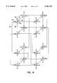
- FIG. 9is a diagram of a 2 ⁇ 2 ⁇ 2 three dimensional (3D) torus topology.
- FIG. 10is a diagram of an example X dimension configuration for one embodiment of a multiprocessor computer system.
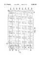
- FIG. 11is a physical layout diagram for one embodiment of a multiprocessor computer system having 256 nodes.
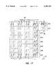
- FIG. 12is a physical layout diagram for one embodiment of a multiprocessor computer system having 128 nodes.
- FIG. 13is a physical layout diagram for one embodiment of a multiprocessor computer system having 512 nodes.
- FIG. 14is a physical layout diagram for one embodiment of a multiprocessor computer system having 1024 nodes.
- FIG. 15is a physical layout diagram for one embodiment of a multiprocessor computer system having 2048 nodes.
- FIG. 16is a physical layout diagram for one embodiment of a multiprocessor computer system having 264 nodes.
- FIG. 17is a physical layout diagram for one embodiment of a multiprocessor computer system having 544 nodes
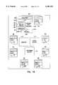
- FIG. 18is a block diagram of a router chip according to the present invention.
- FIG. 19Ais a diagram of a router table lookup mechanism according to the present invention.
- FIG. 19Bis a diagram of an example entry for a local router table employed in the router lookup mechanism of FIG. 19A.
- FIG. 20is a diagram of an example set of routes through a network where a set of destination addresses all have the same local destination address, but have different global destination addresses.
- FIG. 21is another diagram of an example set of routes through a network where a set of destination addresses all have the same local destination address, but have different global destination addresses.
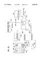
- FIG. 22is a diagram of a mechanism according to the present invention to accomplish the appropriate virtual channel assignment.
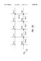
- FIG. 23is a diagram illustrating the operation of the mechanism of FIG. 22.
- multiprocessor computer system 20includes up to n nodes, such as indicated by a first node 22, a second node 24, and an nth node 26.
- the nodesare interconnected by a scalable interconnect network 28, which permits multiprocessor computer systems 20 to be scale from desk side systems to very large supercomputer configurations.
- each node in multiprocessor computer system 20includes at least one processor, such as a first processor 30 and a second processor 32 for node 22.
- An interface circuit 34interfaces with scalable interconnect network 28 and communicates with a memory and directory 36 and an input/output crossbar subsystem 38.
- the multiprocessor computer system 20 illustrated in FIG. 1provides one example environment to implement the below-described hypercube/torus scalable architecture according to the present invention
- the present inventionis in no way limited to this particular application environment.
- many alternative environments using alternative node and interface circuit configurationscan be utilized.
- the topology according to the present invention, as implemented in scalable interconnect network 28,is independent of the complexity of the nodes, such as nodes 22, 24, and 26, interconnected by that topology.
- FIG. 2illustrates, in block diagram form, one embodiment of the interface between scalable interconnect network 28 and two nodes 22 and 24.
- scalable interconnect network 28includes router chips, such as indicated at 50.
- Router chip 50includes eight ports 52, 54, 56, 58, 60, 62, 64 and 66.
- Router ports 52 and 54are respectively coupled to +X dimension physical communication link 70 and -X dimension physical communication link 72.
- Router ports 56 and 58are respectively coupled to +Y dimension physical communication link 74 and -Y dimension physical communication link 76.
- Router ports 60 and 62are respectively coupled to +Z dimension physical communication link 78 and -Z dimension physical communication link 80.
- Router port 64communicates with node 22 and router port 66 communicates with node 24.
- router port 64communicates with node 22 via interface chip 34.
- router port 66communicates with node 24 via interface chip 34'.
- interface chip 34communicates with processors 30 and 32.
- interface chip 34'communicates with processors 30' and 32'.
- this implementation of scalable interconnect network 28transmits packets of information between the processor nodes in the + and -directions of three dimensions and routes packets to two nodes which both include two processors.
- one router chip 50communicates directly with four processors (30, 32, 30' and 32') and six physical communication links (70, 72, 74, 76, 78 and 80).
- FIG. 3illustrates, in block diagram form, another embodiment of the interface between a scalable interconnect network 128 and two nodes 122 and 124.
- scalable interconnect network 128includes router chips, such as indicated at 150.
- Router chip 150includes eight ports 152, 154, 156, 158, 160, 162, 164 and 166.
- Router ports 152 and 154are respectively coupled to +X dimension physical communication link 170 and -X dimension physical communication link 172.
- Router ports 156 and 158are respectively coupled to +Y dimension physical communication link 174 and -Y dimension physical communication link 176.
- Router ports 160 and 162are respectively coupled to +Z dimension physical communication link 178 and -Z dimension physical communication link 180.
- Router port 164communicates with node 122 and router port 166 communicates with node 124.
- router port 164communicates with node 122 via interface chip 134.
- router port 166communicates with node 124 via interface chip 134'.
- interface chip 134communicates with processors 130, 131, 132, and 133.
- interface chip 134'communicates with processors 130', 131', 132', and 133'.
- this implementation of scalable interconnect network 128transmits packets of information between the processor nodes in the + and -directions of three dimensions and routes packets to two nodes which both include four processors.
- one router chip 50communicates directly with eight processors (130, 131, 132, 133, 130', 131', 132', and 133') and six physical communication links (170, 172, 174, 176, 178 and 180).
- the router chips according to the present inventioncan easily scale and accommodate various topologies.
- the networksare double bristled in that two nodes are connected to a single router 50/150.
- additional portsare added to the router chip to permit additional bristling of nodes or the adding of additional dimensions. For example, if two additional ports were added to make a total of ten router ports, + and -directions of a fourth dimension could be added to the interconnect network. Alternatively, the two additional ports could be used to make a quadruple bristled network where four nodes are connected to a single router.
- router chip 50having a single bristled implementation, there could be the + and -directions for the X, Y and Z dimension for connecting a torus, plus an additional single direction fourth dimension for connecting a mesh network.
- the eight router ports of router 50can be used to create up to six-dimensional hypercube topologies.
- Multiprocessor computer system 20employs eight-port router 50 to form up to six-dimensional hypercube systems.
- the hypercube topologyminimizes average hop counts, provides physical link redundancy and maintains linear bisection bandwidth salability.
- FIG. 4An example two dimensional (2D) hypercube topology multiprocessor system is modeled in FIG. 4.
- four router chips 50are employed and are numbered 0 through 3.
- There are two processor ports from each routersuch as those labeled PP from router 0, to couple each router to two nodes to create a double bristled topology.
- the doubled bristled 2D topologyproduces an eight node multiprocessor system having 16 processors in a two processor per node system or 32 processors in a four processor per node system.
- the router linkssuch as those labeled RL from node 0 to nodes 1 and 3, form the 2D hypercube topology.
- extra ports of each routerare used to form express links, such as those labeled EL from node 0 to node 2, resulting in a doubling of the bisection bandwidth of the system.
- FIG. 5An example three dimensional (3D) hypercube topology multiprocessor system is modeled in FIG. 5.
- eight router chips 50are employed and are numbered 0 through 7.
- There are two processor ports from each routersuch as those labeled PP from router 0, to couple each router to two nodes to create a double bristled topology.
- the doubled bristled 3D topologyproduces an 16 node multprocessor system having 32 processors in a two processor per node system or 64 processors in a four processor per node system.
- the router linkssuch as those labeled RL from node 0 to nodes 1, 3, and 7 form the 3D hypercube topology.
- extra ports of each routerare used to form express links, such as those labeled EL from node 0 to node 5, resulting in a doubling of the bisection bandwidth of the system.
- FIG. 6An example four dimensional (4D) hypercube topology multiprocessor system is modeled in FIG. 6.
- 16 router chips 50are employed. There are two processor ports from each router, such as those labeled PP from router 0, to couple each router to two nodes to create a double bristled topology.
- the doubled bristled 4D topologyproduces a 32 node multprocessor system having 64 processors in a two processor per node system or 128 processors in a four processor per node system.
- the router links, such as those labeled RL from node 0form the 4D hypercube topology.
- FIG. 7An example five dimensional (5D) hypercube topology multiprocessor system is modeled in FIG. 7.
- 32 router chips 50are employed. There are two processor ports from each router, such as those labeled PP from router 0, to couple each router to two nodes to create a double bristled topology.
- the doubled bristled 5D topologyproduces a 64 node multprocessor system having 128 processors in a two processor per node system or 256 processors in a four processor per node system.
- the router links, such as those labeled RL from node 0form the 5D hypercube topology. For clarity, only the node 0 links in the fourth and fifth dimensions are shown in FIG. 7.
- FIG. 8An example six dimensional (6D) hypercube topology multiprocessor system is modeled in FIG. 8.
- 64 router chips 50are employed. There are two processor ports from each router, such as those labeled PP from router 0, to couple each router to two nodes to create a double bristled topology.
- the doubled bristled 6D topologyproduces a 128 node multprocessor system having 256 processors in a two processor per node system or 512 processors in a four processor per node system.
- the router linkssuch as those labeled RL from node 0 form the 6D hypercube topology. For clarity, only the node 0 links in the fourth, fifth, and sixth dimensions are shown in FIG. 7.
- Multiprocessor computer system 20scales from desk size systems to very large super computer configurations.
- Scalable interconnect network 28connects multiple nodes via a very high speed, reliable interconnect system.
- Eight port router 50can be employed to scale systems beyond 128 nodes in three dimensional (3D) torus topologies.
- Non-power-of-two systemscan also be configured simply by adding additional cables and reconfiguring routing tables as described below.
- the below descriptiondescribes example large scale system configurations and the corresponding system topologies for example systems from 128 to 2048 nodes.
- Router 50preferable uses differential signaling to enhance its ability to scale as system sizes grow.
- two of the eight portsare typically dedicated to connecting from the routers to two separate nodes, such as indicated in FIGS. 2 and 3. Also as illustrated in FIGS. 2 and 3, the six remaining ports are employed to form + and -direction connections in three dimensions (X, Y, and Z).
- FIG. 9illustrates a 2 ⁇ 2 ⁇ 2 3D torus topology network in the X, Y, and Z dimensions.
- Each node in a 3D torushas communication links in both the + and -directions of the X, Y and Z dimensions.
- a tours topologyforms a ring each dimension where information can transfer from one node, through all the nodes in the same dimension, and back to the origin node.
- a 4 ⁇ 4 ⁇ 4 bidirectional 3D torus topologyis equivalent to the 6D multiprocessor topology illustrated in FIG. 8 having 128 nodes.
- the 3D torus topologyis utilized for systems having more than 128 nodes, because a double bristled 60 multiprocessor contains 128 nodes.
- each port on router 50has two router tables (shown in FIGS. 18 and 19) referred to as a local router table and a global router table.
- the local router tablecontains 128 locations and the global router table contains 16 locations. If a packet's source processor is in the same global partition as the destination processor, local tables will describe all of the routes required for the requests to reach their destination and for the response to return to the source. If the destination is in a different global partition, the global tables are used to describe how to get from one partition to the next. As is described below, because the router tables indicate which output port to take on the next router chip, the router chips which are one hop from the destination global partition also use the local table.
- a router PC board 86includes four routers, such as router 50, which are labeled R and numbered 0, 1, 2 and 3. In this configuration, the X dimension does not scale as system sizes grow. In this implementation, the X dimension connections are implied in all system topologies greater than 128 nodes.
- Each of the four routers 50 on router PC board 86is coupled to two nodes which are labeled N.
- Each node in the embodiment illustrated in FIG. 10comprises two processors labeled P.
- each router chip 50is connected between router chips to form the Y and Z dimensions for the torus topologies used in larger systems.
- FIG. 11illustrates one embodiment of a system having 256 nodes interconnected with 128 router chips 50 in a double bristled torus topology.
- the +directions of the Y and Z dimensionsare indicated with arrows.
- FIG. 12illustrates one embodiment of a system having 128 nodes interconnected with 64 router chips 50 in a double bristled torus topology.
- the +directions of the Y and Z dimensionsare indicated with arrows.
- FIG. 13illustrates one embodiment of a system having 512 nodes interconnected with 256 router chips 50 in a double bristled torus topology.
- the +directions of the Y and Z dimensionsare indicated with arrows.
- global partitions GP0 and GP3each comprise four cabinets 88, while global partitions GP2 and GP3 are interleaved within a total of eight cabinets.
- FIG. 14illustrates one embodiment of a system having 1024 nodes interconnected with 512 router chips 50 in a double bristled torus topology.
- the +directions of the Y and Z dimensionsare indicated with arrows.
- there are global partitions GP0 through GP7where each global partition comprises eight half portions of cabinets 88.
- FIG. 15illustrates one embodiment of a system having 2048 nodes interconnected with 1024 router chips 50 in a double bristled torus topology.
- the +directions of the Y and Z dimensionsare indicated with arrows.
- there are global partitions GP0 through GP15where each global partition comprises eight half portions of cabinets 88.
- FIGS. 11 through 15illustrate power-of-two systems.
- the systemsare not limited to power-of-two configurations.
- FIG. 16illustrates one embodiment of a 264 node system comprising a first portion 89 which is 4 ⁇ 4 ⁇ 8 torus within eight cabinets, and a second portion 91 which is 4 ⁇ 1 ⁇ 1 torus within one cabinet.
- the 264 node system of FIG. 16comprises global partitions GP0, GP1, and GP3.
- Global partitions GP0 and GP1each include four cabinets 88 with 32 nodes within each cabinet.
- Global partition GP3includes one cabinet 88, which has 8 nodes.
- FIG. 17Another example of a non-power of system having 544 nodes is illustrated in FIG. 17.
- This 544 node systemcomprises a first portion 93 which is 4 ⁇ 8 ⁇ 8 torus within 16 cabinets, and a second portion 95 which is a 4 ⁇ 2 ⁇ 2 torus within one cabinet.
- the 544 node system of FIG. 17comprises global partitions GP0 through GP7.
- Global partitions GP0 and GP1each include five half portions of cabinets 88, while GP2 through GP7 each include four half portions of cabinets 88.
- Router chip 50(or 150) according to the present invention is illustrated in block diagram form in FIG. 18.
- Router chip 50includes eight differential ports 52, 54, 56, 58, 60, 62, 64, and 66 for coupling to up to eight pairs of unidirectional physical links per router.
- Four virtual channels, such as indicated at 90, 92, 94, and 96 for port 52,are assigned to each physical channel, where two virtual channels are assigned to requests and two virtual channels are assigned to responses. A more detailed discussion of virtual channels is provided below.
- a source synchronous driver/receiver (SSD/SSR) block 98creates and interprets high-speed, source synchronous signals used for inter-chip communication.
- a link level protocol (LLP) block 100interfaces to SSD/SSR block 98 and provides transmission of data between router chips.
- a router receive block 102accepts data from LLP block 100, manages virtual channels, and forwards data to router tables 104 and 106 and a router send block 108.
- Router receive block 102includes virtual channel management logic, dynamically allocated memory queues, bypass logic, and fairness logic which ages packets when they fail to make progress.
- Router send block 108drives data into LLP block 102 for transmission to other router chips.
- Global router table 104 and local router table 106together form a two level routing table which provides routing information for messages as they pass through the network. Router tables 104 and 106 are indexed by the message destination and direction, and provide a new message direction via an exit port ID. Since routing is pipelined with link arbitration, the routing tables must include instructions as to how to traverse to the next router chip.
- router chip 50For clarity, only port 52 is shown in detail, but all of the eight ports of router chip 50 comprise: virtual channels 90, 92, 94, and 96 a source synchronous driver/receiver (SSD/SSR) block 98; a link level protocol (LLP) block 100; a router receive block 102; router tables 104 and 106; and a router send block 108.
- SSD/SSRsource synchronous driver/receiver
- LLPlink level protocol
- a router arbiter block 110executes two levels of arbitration for the router chip.
- the first level arbiterperforms a wavefront arbitration to selects a near-optimal combination of grants for a given arbitration cycle and informs receiver block 102 which requests won. Ports which are not used during the first level arbitration have a second chance to be granted by the second level or bypass arbiter. Fairness via age comparison is contained within the arbiter block.
- a router crossbar block 112includes a series of multiplexers which control data flow from receiver ports to sender ports. Once arbiter block 110 decides on the winners, arbiter block 110 forwards this information to crossbar block 112 which provides connections from receivers to senders.
- a router local block 114is a control point of router chip 50. Router local block 114 provides access to all router controls and status registers including router tables 104 and 106, error registers (not shown), and protection registers (not shown). Router local block 114 also supports special vector message routing, which is used during system configuration. In one embodiment, router local block also supports hardware barrier operation. Such hardware barrier operations are described in detail in the co-pending patent application entitled "SERIALIZED, RACE-FREE VIRTUAL BARRIER NETWORK,” filed on even date herewith, and which is herein incorporated by reference.
- Router chip 50does not assume any particular message length based on header information, but routes a message according to header information until a tail bit is detected.
- the message headercontains all routing and priority information required to complete the message route.
- Several other fields in the message headerare used for memory, processor, and I/O operations. However, only a few fields are decoded by router chip 50. The remaining fields are passed along unchanged as data. Network and node operations are separated as much as possible to permit future networks or future nodes to be interchanged with minimal compatibility problems.
- Message header packetsfollow tail micropackets. Once a micropacket is detected by router chip 50 with its tail bit set in a sideband (discussed below), the next micropacket to the same virtual channel is assumed to be a header. After reset, the first micropacket received by router chip 50 is assumed to be a header. Message body packets are treated as all data, except for sideband information.
- a sidebandis a field of information that accompanies each micropacket.
- router 50employs the sideband to tag each micropacket with a virtual channel, to communicate virtual channel credits, and to indicate error and tail conditions.
- Error bit encodingindicates that the micropacket accompanying the error bit indicator encountered a memory ECC error or other type of source error. It is necessary to encode the bit error for every micropacket because, for example, an error might not be detected until the end of a block read and the header of a message will already be routed through the network and cannot indicate an error state.
- each messagehas an age associated with it and message age influences internal arbitration in router chip 50, where priority is given to older messages.
- message ageinfluences internal arbitration in router chip 50, where priority is given to older messages.
- routing chip 50supports two types of routing which are: 1) table-driven routing for standard, high-speed routing based on internal routing tables; and 2) vector routing for initialization, based on routing instructions included in the message header.
- Table-driven routing messagesare injected into the network with a destination address and an initial direction (i.e., exit port ID), and the routing tables contain the information necessary to deliver the message to its destination.
- Vector routingrequires the source node to completely specify the routing vector when the message is injected into the network.
- the vector routing feature of router chip 50is used to for access to router registers and some interface circuit registers.
- Vector routingprovides network exploration and routing table initialization and is a low performance routing.
- the vector routing functionpermits software to probe the network topology and set up routing tables and ID fields through uncached reads and writes. Once software programs a vector route in a vector route register, software may execute uncached reads and writes which initiate vector route packets.
- vector route messagesare always two micropackets in length.
- the first micropacketis a standard header, with command encoding indicating read or write, and direction field indicating router core.
- the vector route headeris routed directly to router local block 114.
- the second micropacketis examined for the vector route data.
- Vector route dataconsists of a vector having vector elements, which each comprise a direction pointer.
- Direction pointersmay include either an output port ID or a vector terminator.
- local block 114examines the current vector and routes according to the right-most vector element. The entire route vector is then shifted right by the number of bits in a vector element, and a return direction port ID is shifted in as the most significant bits. A vector request routed message has reached its destination when the right-most vector element contains binary some indicator, such as for example, 0000 for a four bit vector element.
- the request packetreaches its destination (the current request vector is all 0s), a response header is formulated and the message is sent back to the port it entered on, but on the reply virtual channel.
- the new vectoris generated such that the least significant nibble becomes the most significant nibble.
- the right-most vector elementsare used to route the message and the vector is shifted right. The message eventually reaches the originating node via the same route on which it left.
- Routing tables 104 and 106are distributed across scalable interconnection network 28 each port of each router and provide a high-speed, flexible routing strategy which can be adapted through software. Routing tables 104 and 106 determine the path taken by messages between any two nodes in the system. Routing tables 104 and 106 must be programmed in a way which does not introduce any cycles in the directed routing graphs. As dictated by routing tables 104 and 106, the physical message paths are static. The message paths are programmed into routing tables 104 and 106 by software.
- routing tables 104 and 106can be modified during system operation.
- this software manipulation of routing tables 104 and 106can be used only for fault avoidance, not for congestion control.
- scalable interconnection network 28never routes a message adaptively through the network by "skipping" a desired route when a necessary link is unavailable due to congestion.
- routing table discussionrefers to a system having two processors per node, such as the system illustrated in FIG. 2 above.
- a router tableis indexed by a network destination identification (ID) and provides the next direction a message should travel.
- IDnetwork destination identification
- a router tablehas a unique entry for each other node in the system. Since this solution is not typically feasible due to the size of the table required, the routing tables, according to the present invention, are broken into a two-level hierarchy. In one embodiment of this two-level hierarchy, there is one router table entry for each of 128 nodes (64 routers) to a given local subnetwork or global partition, as well as a router table entry for each of up to 16 local subnetworks.
- Table I at the end of this Description of the Preferred Embodiments sectionprovides one specific example of a TLB mapping showing how the node destination address is broken into global portions for addressing into the global and local tables for a system scalable from 2 to 2048 nodes.
- the specific example TLB mapping of Table Ishow how the global and local address bits can be interleaved if desired to accommodate certain physical configurations.
- Table II at the end of this Description of the Preferred Embodiments sectionprovides another specific example of a TLB mapping showing how the node destination address is broken into global portions for addressing into the global and local tables for a system scalable from 2 to 256 nodes.
- the specific example TLB mapping of Table IIshows how the global and local address bits are not interleaved for accommodating certain other physical configurations.
- the specific example TLB mapping of Table IIalso shows that this system embodiment of up to 256 nodes includes two extra local bits and one extra global to permit future expansion from 272 to 4096 nodes.
- the global destination ID portionmust have exactly one bit in the least significant five bits of the destination for systems with greater than 512 nodes. This ensures that an invalidate engine (not shown) maps out nodes appropriately in systems greater than 512 nodes. Without this, the upgrade path would require a 32 node increment to be spread across two half populated cabinets.
- the global bitsare preferably avoided all together. This allows for more routing flexibility and less required configuration, as all routing comes from the local table. It should, however, be noted that the scheme used for greater than 128 nodes may also be used for less than or equal to 128 nodes.
- a given router chip 50 in the scalable interconnect network 28must decide whether to use the global or local table to look up a direction to take. The value looked up is not used immediately, but is attached to the packet header and used on the next router chip.
- FIG. 19Aillustrates a router table lookup mechanism illustrated generally at 200.
- a physical destination ID indicated at 202includes a global destination ID portion 204 and a local destination ID portion 206.
- global destination ID 204includes four bits, while the local destination ID 206 includes seven bits.
- Global destination ID 204indexes global routing table 104 having entries 208.
- Local destination ID 206indexes local routing table 106 having entries 210.
- Global destination ID 204is compared, as indicated at decision point 212, to a current node's global address stored in register 214.
- Global destination ID 204is also compared at decision point 216 to a next -global address stored in register 218.
- Global destination ID 204is also compared at decision point 220 to a next +global address stored in register 222.
- a direction field from the message headeris indicated at 224 and is four bits in the embodiment illustrated FIG. 19A.
- Direction field 224 from the message header 224is compared at decision point 224 to -global direction bits stored in register 226.
- Direction field 224 from the message headeris also compared at decision point 228 to +global direction bits stored in register 230.
- the output from decision points 220 and 228 and a +global valid bit stored in register 232are logically AND'd by an AND gate 234.
- the output of decision points 216 and 224 and a -global valid bit stored in register 236are logically AND'd by an AND gate 238.
- the outputs of AND gates 234 and 238, the output of decision point 212, and a force local table bit stored in register 240are logically OR'd by an OR gate 242.
- FIG. 19Billustrates an example entry 210 for local router table 106.
- Local router table entry 210includes a -global direction field, a +global direction field, and a local direction field.
- local router table 106provides the -global direction field on a line 244, the +global direction field on a line 246, and the local direction field on a line 248 to a multiplexer 250.
- Multiplexer 250provides one of the direction fields 244, 246, or 248 to one input of a multiplexer 254 based on the state of the outputs of AND gates 234 and 238.
- Global table 104provides a global direction field on a line 252 to a second input of multiplexer 254.
- Multiplexer 254provides either the global direction field from line 252 or the selected direction field from multiplexer 250 to an output line 256 based on a force local signal provided from OR gate 242.
- the selected four bit direction field from multiplexer 254 provided on line 256includes an exit port ID of three bits to determine through which one of the eight ports of the next router chip 50 the message is to be routed, and includes a virtual channel least significant bit (lsb).
- local router table 106provides an exhaustive list of local destinations within a local subnetwork
- global router table 104provides an exhaustive list for each global destination.
- Local router table 106is used to determine the next direction when the global bits of the destination ID match the global address of the current router or they match that of the plus or minus neighboring local subnetwork and the output port is the one designated as that which connects directly to that neighboring local subnetwork.
- global router table 104is used to determine the next direction.
- the global ID/port registers 214, 218, 222, 226, 230, 232, and 234 and the force local table register 240 in each router chip 50are software programmable via a global port definition register (not shown) in router local block 114.
- An Example set of routes through a network where a set of destination addresses all have the same local destination address, but have different global destination addressesis illustrated in diagram form in FIG. 20.
- three routesare performed. All of the three routes only use the local router table entries.
- the dashed linesrepresent hops in a given route that carry the local direction field of the local router table; the dotted lines represent hops in a given route that carry the +global direction field in the local router table; and the dotted/dashed lines represent hops in a given route that carry the -global direction field.
- This particular exampledoes not illustrate any hops that carry the global router table entries.
- the first routepasses through an input port 300 of router 12, as indicated by solid line 302.
- the first routeis then routed from router 12 in global partition 2 to router 13 in global partition 3 carrying the +global direction field in the local router table, as indicated by dotted line 304.
- the first routeis then routed from router 13 in global partition 3 to the router 3 (the destination) in global partition 3 carrying the local direction field in the local router table, as indicated by dashed line 306.
- the second routepasses through input port 300 of router 12, as indicated by solid line 302.
- the second routeis then routed from router 12 in global partition 2 to the router 2 (the destination) in global partition 2 carrying the local direction field in the local router table, as indicated by dashed line 308.
- the third routepasses through input port 300 of router 12, as indicated by solid line 302.
- the third routeis then routed from router 12 in global partition 2 to router 11 in global partition 1 carrying the -global direction field in the local router table, as indicated by dotted/dashed line 310.
- the third routeis then routed from router 11 in global partition 1 to the router 1 (the destination) in global partition 1 carrying the local direction field in the local router table, as indicated by dashed line 312.
- FIG. 21Another example set of routes through a network where a set of destination addresses all have the same local destination address, but have different global destination addresses is illustrated in diagram form in FIG. 21.
- two routesare performed.
- the dashed linesrepresent hops in a given route that carry the local direction field of the local router table;
- the dotted linesrepresent hops in a given route that carry the +global direction field in the local router table;
- the single dotted/single dashed linesrepresent hops in a given route that carry the -global direction field;
- the double dotted/single dashed linesrepresent hops in a given route that carry the global router table entry.
- the first routepasses through an input port 400 of router 12, as indicated by solid line 402.
- the first routeis then routed from router 12 in global partition 2 to router 13 in global partition 3 carrying the global entry in the global router table, as indicated by double dotted/single dashed line 404.
- the first routeis then routed from router 13 in global partition 3 to router 14 in global partition 4 carrying the +global direction field in the local router table, as indicated by dotted line 406.
- the first routeis then routed from router 14 in global partition 4 to the router 4 (the destination) in global partition 4 carrying the local direction field in the local router table, as indicated by dashed line 408.
- the second routepasses through input port 400 of router 12, as indicated by solid line 402.
- the second routeis then routed from router 12 in global partition 2 to router 11 in global partition 1 carrying the global entry in the global router table, as indicated by double dotted/single dashed line 410.
- the second routeis then routed from router 11 in global partition 1 to router 10 in global partition 0 carrying the -global direction field in the local router table, as indicated by single dotted/single dashed line 412.
- the second routeis then routed from router 10 in global partition 0 to the router 0 (the destination) in global partition 0 carrying the local direction field in the local router table, as indicated by dashed line 414.
- the scalable interconnect network 28utilizes the virtual channels to perform deadlock-free routes, create separate request and reply networks, and provide reserved buffers for congestion relief for certain messages. Each message is associated with one of the four virtual channels. In one embodiment, when a message enters a router port, the message is written into the virtual channel buffer indicated by a virtual channel field in the sideband. Congestion control is achieved by allowing messages to switch between the two virtual channels.
- a single physical router linksupports interleaving of messages on different virtual channels, but within one virtual channel a message must remain continuous. For example, after router chip 50 sends four micropackets across a physical link on virtual channel 0, router chip 50 can choose to send any number of packets on virtual channels 1-3 before returning to virtual channel 0 to complete the first message. This feature allows router chip 50 to maximize utilization of virtual channel buffers by sending partial messages when only a small amount of space is available at the destination.
- high priority messagescan also cut through lower priority messages across a given physical link, assuming the messages do not share the same virtual channel.
- each micropacketIn order to implement this virtual channel cut-through, each micropacket must be tagged with its virtual channel number in a sideband. This is why virtual channel identification is not contained in the message header in this embodiment.
- Scalable interconnect network 28must break cycles of dependencies, as these would cause the network to deadlock.
- the three types of cyclic dependencies that scalable interconnect network 28 is designed to breakare: 1) request-response cycles; 2) turn cycles; and 3) physical cycles. The latter two may only have a semantic difference, but they are differentiated below.
- Requeststrigger responses which means that cycles are introduced if they use dependent resources. This cycle is broken through the use of virtual channels. All requests travel on one class of virtual channel and all responses on another class of virtual channel. In one embodiment, cache coherency mechanisms in interface circuit guarantee that all traffic fits into one of these two classes, and that no dependencies are introduced from requests to responses or from responses to requests.
- +z, -z, -y, and -xcan be routed in any order, but the dateline cannot not be crossed in x or y;
- +y, -y, and -xcan be routed in any order, but the dateline cannot be crossed in x;
- router chip 50does not support reflections (i.e., same entrance and exit port). This scheme, combined with the system growth path, provides deadlock avoidance, full use of bisection bandwidth, and multiple paths between nodes.
- virtual channelsare used to break physical cycles in double bristled systems with greater than 128 nodes, such as for a 4 ⁇ 8 ⁇ 4 double bristled torus topology 256 node system.
- Physical cyclesare only a concern for cycles with greater than four vertices, such as for the Y dimension of the 4 ⁇ 8 ⁇ 4 torus topology system.
- FIG. 22A mechanism according to the present invention to accomplish the appropriate virtual channel assignment is illustrated in diagram form in FIG. 22.
- the six inter-router portssuch as ports 52, 54, 56, 58, 60, and 62 of router chip 50 illustrated in FIG. 2, are divided into three pairs, where each pair defines a dimension.
- this pairingis accomplished via a port -- mate field 500 stored in a port information register 502 in router chip 50.
- Port -- mate field 500is a three bit field that matches the lower three bits of the direction field, indicated at 504, on an incoming header packet.
- the three bit port -- mate field 500is relative to the input port. Table III at the end of this Description of the Preferred Embodiments section provides one embodiment of each input port's relative mate.
- the least significant bit (lsb) of the first word of the header micropacketis defined as the "V" bit, indicated at 506, which becomes the lsb of the output virtual channel (nxt -- vch -- lsb).
- the next router chip 50 in a given routeemploys the nxt -- vch -- lsb to determine which type of virtual channel should be used for routing from the next router chip 50.
- a virtual channel select enable (vch -- sel -- en) bit 508 stored in a global information register 510 in router chip 50is used to control a multiplexer 512.
- the nxt vch -- lsb -- bitis used to indicate the lsb of the next link on line 514 from multiplexer 512.
- the vch -- sel -- en bit 508is cleared, which causes packets to route from source to destination on the same virtual channel.
- the vch -- sel -- en bit 508is set and the lsb of the virtual channel on line 514 is set using virtual channel lsb on line 256b from the indexed entry from router table 104 or 106 and the port -- mate field 500.
- the indexing of router tables 104 and 106is described above and illustrated in FIGS. 19A-B.
- a comparator 516compares the direction field on line 256a from the indexed entry from router table 104 or 106 to the port -- mate field 500 from port information register 502 to determine whether the output port of the next router chip is the mate to the input port of the next router chip.
- the output of comparator 516controls a multiplexer 518, which provides its output to multiplexer 512.
- the virtual channel lsb on line 256b from lookup table 104 or 106is logically OR'd with the incoming nxt -- vch -- lsb bit 506 by an OR gate 520, and this OR'd value is provided as the nxt -- vch -- lsb on line 514. If the vch -- sel -- en bit is set and the output port is not the mate to the input port, the nxt -- vch -- lsb on line 514 is the virtual channel lsb on line 256b from lookup table 104 or 106.
- nxt -- vch -- lsbis the virtual channel bit from the routing tables
- nxt -- vch -- lsbis obtained by logically ORing the virtual channel bit from routing tables with the virtual channel bit from message header.
- FIG. 23illustrates a route starting on virtual channel 0 from (Y,Z) source (0,0) to (Y,Z) destination (4,1). As illustrated, virtual channel 0 is used to route from router chip (0,0) to router chip (1,0). Virtual channel 0 is used to route from router chip (1,0) to router chip (2,0).
- router chip (1,0)the virtual channel bit from the router tables is a one, because of a dateline crossing.
- the virtual channel bit from the router tables in router chip (1,0)is logically OR's with the incoming V bit, which produces a one.
- virtual channel 1is used to route from router chip (2,0) to router chip (3,0). Once on virtual channel 1, the route stays on virtual channel 1, until a corner is turned.
- virtual channel 1is used to route from router chip (3,0) to router chip (4,0).
- the virtual channel bit from the router tablesis a zero, which determines the virtual channel to be used on the corner turn route from router chip (4,0) to router chip (4,1).
- virtual channel 0is used to route from router chip (4,0) to router chip (4,1).
- This design approachpermits virtual channel switches at a dateline crossing or at all corner turns (i.e., switching dimensions).
- the lsb of the virtual channel fieldis used to prevent deadlock in the torus topology in large systems having more than four locations in at least one dimension, such as for a 4 ⁇ 8 ⁇ 4 torus topology.
- Thisallows deadlock free and virtual channel balanced network to be implemented in software. It also allows smaller systems which are deadlock free by nature, to assign certain reference types. For example in one embodiment of a smaller system, I/O references are assigned to virtual channels 1 and 3, while normal processor-to-processor communication are assigned virtual channels 0 and 2.
- router chip 50achieves the goal of always having at least two non-overlapping paths connecting every pair of nodes connected to a router chip 50. Typically, there are multiple paths available. This permits the system to bypass broken router chips or network links.
- each network linkis protected by a check code and link-level logic which retries any corrupted transmissions and provides tolerance of transient errors.
- the hypercube and torus topologies described abovecan sustain multiple faults and still be reconfigured in a fully connected fashion.
- the two-level router table(router tables 104 and 106), when properly implemented, contains only a few models which are connected but cannot be routed, and these typically are unlikely and degenerate cases.
- the present inventionpermits small systems to be constructed in a hypercube topology which offers high bandwidth connections, low latencies, and physical link redundancy while maintaining linear bisection bandwidths as systems scale. Nevertheless, as systems increase the number of processors, the number of physical connections required to support the hypercube topology increases significantly, resulting in higher system costs and manufacturing complexities. To this end, larger systems according to the present invention can be constructed in a torus topology having more than four locations in at least one dimensions. Such torus topologies according to the present invention permit system performance to be maintained at a relatively high level, yet reduce the number of physical connections between processors. With fewer physical connections between processors, system costs are significantly reduced. Since the torus connection is a ring of processors which grows as systems become larger, multiple torus rings can be formed in the system to keep interconnect bandwidth high and latencies between processors low.
Landscapes
- Engineering & Computer Science (AREA)
- Physics & Mathematics (AREA)
- Computer Hardware Design (AREA)
- Theoretical Computer Science (AREA)
- Mathematical Physics (AREA)
- Software Systems (AREA)
- General Engineering & Computer Science (AREA)
- General Physics & Mathematics (AREA)
- Multi Processors (AREA)
Abstract
Description
TABLE I __________________________________________________________________________Example TLB Mapping of Dimensions to Physical Node Number Network Dimensions N.sub.10 N.sub.9 N.sub.8 N.sub.7 N.sub.6 N.sub.5 N.sub.4 N.sub.3 N.sub.2 N.sub.1 N.sub.0 Node Count x y z G.sub.3 L.sub.6 G.sub.2 L.sub.5 G.sub.1 L.sub.4 G.sub.0 L.sub.3 L.sub.2 L.sub.1 L.sub.0 __________________________________________________________________________1056 to 2048 4 16 16 z.sub.3 y.sub.3 z.sub.2 y.sub.2 z.sub.1 y.sub.1 z.sub.0 y.sub.0 x.sub.1 x.sub.0 nd 544 to 1024 4 16 8 0 y.sub.3 z.sub.2 y.sub.2 z.sub.1 y.sub.1 z.sub.0 y.sub.0 x.sub.1 x.sub.0 nd 264 to 512 4 8 8 0 0 z.sub.2 y.sub.2 z.sub.1 y.sub.1 z.sub.0 y.sub.0 x.sub.1 x.sub.0 nd 132 to 256 4 8 4 0 0 0 y.sub.2 z.sub.1 y.sub.1 z.sub.0 y.sub.0 x.sub.1 x.sub.0 nd 68 to 128 4 4 4 0 z.sub.1 0 y.sub.1 0 z.sub.0 0 y.sub.0 x.sub.1 x.sub.0 nd 33 to 64 4 4 2 0 0 0 y.sub.1 0 z.sub.0 0 y.sub.0 x.sub.1 x.sub.0 nd 17 to 32 4 2 2 0 0 0 0 0 z.sub.0 0 y.sub.0 x.sub.1 x.sub.0 nd 9 to 16 2 2 2 0 0 0 0 0 z.sub.0 0 y.sub.0 0 x.sub.0 nd 5 to 8 1 1 1 0 0 0 0 0 0 0 y.sub.0 0 x.sub.0 nd 3 to 4 1 1 1 0 0 0 0 0 0 0 0 0 x.sub.0 nd 2 1 1 1 0 0 0 0 0 0 0 0 0 0 nd __________________________________________________________________________
TABLE II __________________________________________________________________________Example TLB Mapping of Dimensions to Physical Node Number Network Dimensions D.sub.10 D.sub.9 D.sub.8 D.sub.7 D.sub.6 D.sub.5 D.sub.4 D.sub.3 D.sub.2 D.sub.1 D.sub.0 Node Count x y z G.sub.3 L.sub.6 L.sub.5 G.sub.2 G.sub.1 G.sub.0 L.sub.4 L.sub.3 L.sub.2 L.sub.1 L.sub.0 __________________________________________________________________________272 to 4096.sup.a ? ? ? f.sub.2 f.sub.1 f.sub.0 y.sub.2 y.sub.1 y.sub.0 z.sub.1 z.sub.0 x.sub.1 x.sub.0 nd 132 to 256 4 8 4 0 0 0 y.sub.2 y.sub.1 y.sub.0 z.sub.1 z.sub.0 x.sub.1 x.sub.0 nd 68 to 128 4 4 4 0 0 0 0 y.sub.1 y.sub.0 z.sub.1 z.sub.0 x.sub.1 x.sub.0 nd 33 to 64 4 2 4 0 0 0 0 0 y.sub.0 z.sub.1 z.sub.0 x.sub.1 x.sub.0 nd 17 to 32 4 1 4 0 0 0 0 0 0 z.sub.1 z.sub.0 x.sub.1 x.sub.0 nd 9 to 16 4 1 2 0 0 0 0 0 0 0 z.sub.0 x.sub.1 x.sub.0 nd 5 to 8 4 1 1 0 0 0 0 0 0 0 0 x.sub.1 x.sub.0 nd 3 to 4 1 1 1 0 0 0 0 0 0 0 0 0 x.sub.0 nd 2 1 1 1 0 0 0 0 0 0 0 0 0 0 nd __________________________________________________________________________ .sup.a Future expansion
TABLE III ______________________________________ Encoding of Port.sub.-- Mate Field PTA PTB PTC PTD PTE PTF PTG PTH Output Input Input Input Input Input Input Input Input Port Port Port Port Port Port Port Port Port ______________________________________ A n/a 7 6 5 4 3 2 1 B 1 n/a 7 6 5 4 3 2C 2 1 n/a 7 6 5 4 3D 3 2 1 n/a 7 6 5 4E 4 3 2 1 n/a 7 6 5F 5 4 3 2 1 n/a 7 6G 6 5 4 3 2 1 n/a 7H 7 6 5 4 3 2 1 n/a ______________________________________
Claims (10)
Priority Applications (4)
| Application Number | Priority Date | Filing Date | Title |
|---|---|---|---|
| US08/971,591US6101181A (en) | 1997-11-17 | 1997-11-17 | Virtual channel assignment in large torus systems |
| DE69806798TDE69806798T2 (en) | 1997-11-17 | 1998-11-16 | ALLOCATION OF VIRTUAL CHANNELS IN LARGE TORUS SYSTEMS |
| EP98957995AEP1031096B1 (en) | 1997-11-17 | 1998-11-16 | Virtual channel assignment in large torus systems |
| PCT/US1998/024422WO1999026162A1 (en) | 1997-11-17 | 1998-11-16 | Virtual channel assignment in large torus systems |
Applications Claiming Priority (1)
| Application Number | Priority Date | Filing Date | Title |
|---|---|---|---|
| US08/971,591US6101181A (en) | 1997-11-17 | 1997-11-17 | Virtual channel assignment in large torus systems |
Publications (1)
| Publication Number | Publication Date |
|---|---|
| US6101181Atrue US6101181A (en) | 2000-08-08 |
Family
ID=25518583
Family Applications (1)
| Application Number | Title | Priority Date | Filing Date |
|---|---|---|---|
| US08/971,591Expired - LifetimeUS6101181A (en) | 1997-11-17 | 1997-11-17 | Virtual channel assignment in large torus systems |
Country Status (4)
| Country | Link |
|---|---|
| US (1) | US6101181A (en) |
| EP (1) | EP1031096B1 (en) |
| DE (1) | DE69806798T2 (en) |
| WO (1) | WO1999026162A1 (en) |
Cited By (85)
| Publication number | Priority date | Publication date | Assignee | Title |
|---|---|---|---|---|
| US20020147841A1 (en)* | 2001-01-04 | 2002-10-10 | Lee Whay S. | Scalable routing scheme for a multi-path interconnection fabric |
| US20020191536A1 (en)* | 2001-01-17 | 2002-12-19 | Laforge Laurence Edward | Algorithmic method and computer system for synthesizing self-healing networks, bus structures, and connectivities |
| US20030023893A1 (en)* | 2001-05-07 | 2003-01-30 | Lee Whay S. | Fault-tolerant routing scheme for a multi-path interconnection fabric in a storage network |
| US20030021227A1 (en)* | 2001-05-07 | 2003-01-30 | Lee Whay S. | Fault-tolerant, self-healing routing scheme for a multi-path interconnection fabric in a storage network |
| US20030023776A1 (en)* | 2001-06-28 | 2003-01-30 | Nokia Corporation | Method for enabling a communication between processes, processing system, integrated chip and module for such a chip |
| US20030023749A1 (en)* | 2001-05-07 | 2003-01-30 | Lee Whay S. | Routing scheme using preferred paths in a multi-path interconnection fabric in a storage network |
| US20030065969A1 (en)* | 2001-09-28 | 2003-04-03 | Sun Microsystems, Inc. | Discovery of nodes in an interconnection fabric |
| US20030065821A1 (en)* | 2001-09-28 | 2003-04-03 | Lee Whay S. | Mapping of nodes in an interconnection fabric |
| US20030118048A1 (en)* | 1997-08-22 | 2003-06-26 | Avici Systems | Internet switch router |
| US20030140022A1 (en)* | 2001-12-28 | 2003-07-24 | Autodesk, Inc. | Turn restriction handling enhancement |
| US20030198189A1 (en)* | 2002-04-19 | 2003-10-23 | Dave Roberts | Network system having an instructional sequence for performing packet processing and optimizing the packet processing |
| US20030200295A1 (en)* | 2002-04-19 | 2003-10-23 | Roberts David Gary | Network system having a virtual-service-module |
| US20030212776A1 (en)* | 2002-05-07 | 2003-11-13 | Roberts David Gary | Methods and systems for changing a topology of a network |
| US6654381B2 (en)* | 1997-08-22 | 2003-11-25 | Avici Systems, Inc. | Methods and apparatus for event-driven routing |
| US20040019728A1 (en)* | 2002-07-23 | 2004-01-29 | Sharma Debendra Das | Multiple hardware partitions under one input/output hub |
| US6718428B2 (en) | 2000-12-18 | 2004-04-06 | Sun Microsystems, Inc. | Storage array interconnection fabric using a torus topology |
| US6741561B1 (en) | 2000-07-25 | 2004-05-25 | Sun Microsystems, Inc. | Routing mechanism using intention packets in a hierarchy or networks |
| US6766482B1 (en) | 2001-10-31 | 2004-07-20 | Extreme Networks | Ethernet automatic protection switching |
| US6775843B1 (en)* | 1999-10-14 | 2004-08-10 | Sony Corporation | Method and apparatus for digital TV channel mapping |
| US20040168026A1 (en)* | 2003-02-20 | 2004-08-26 | Wu Chia Y. | Write posting memory interface with block-based read-ahead mechanism |
| US20040165617A1 (en)* | 2003-02-20 | 2004-08-26 | Wu Chia Y. | Transmitting odd-sized packets over a double data rate link |
| US20040230719A1 (en)* | 2003-05-12 | 2004-11-18 | Sun Microsystems, Inc. | Streaming protocol for storage devices |
| US6826148B1 (en) | 2000-07-25 | 2004-11-30 | Sun Microsystems, Inc. | System and method for implementing a routing scheme in a computer network using intention packets when fault conditions are detected |
| US20050002387A1 (en)* | 2003-06-06 | 2005-01-06 | International Business Machines Corporation | One-bounce network |
| US20050018665A1 (en)* | 2003-07-24 | 2005-01-27 | Alcatel | Software configurable cluster-based router using stock personal computers as cluster nodes |
| US6925056B1 (en) | 2000-07-25 | 2005-08-02 | Sun Microsystems, Inc. | System and method for implementing a routing scheme using intention packets in a computer network |
| US20050195808A1 (en)* | 2004-03-04 | 2005-09-08 | International Business Machines Corporation | Multidimensional switch network |
| US20050238030A1 (en)* | 2004-04-27 | 2005-10-27 | Asheesh Kashyap | Nodal computer network |
| US7002958B1 (en)* | 1999-09-10 | 2006-02-21 | Pluris, Inc. | Method for load-balancing with FIFO guarantees in multipath networks |
| US20060114923A1 (en)* | 2004-11-29 | 2006-06-01 | Overgaard Mark D | Disaggregated star platform management bus architecture system |
| US20070133560A1 (en)* | 2005-12-07 | 2007-06-14 | Nam Kook J | Method and apparatus for processing packet in high speed router |
| US20070140280A1 (en)* | 2005-12-16 | 2007-06-21 | Samsung Electronics Co., Ltd. | Computer chip for connecting devices on the chip utilizing star-torus topology |
| US7379424B1 (en) | 2003-08-18 | 2008-05-27 | Cray Inc. | Systems and methods for routing packets in multiprocessor computer systems |
| US7386628B1 (en) | 2002-05-08 | 2008-06-10 | Nortel Networks Limited | Methods and systems for processing network data packets |
| US7401161B2 (en) | 2000-12-18 | 2008-07-15 | Sun Microsystems, Inc. | High performance storage array interconnection fabric using multiple independent paths |
| US7406086B2 (en) | 1999-09-29 | 2008-07-29 | Silicon Graphics, Inc. | Multiprocessor node controller circuit and method |
| US20080294778A1 (en)* | 2007-05-25 | 2008-11-27 | Microsoft Corporation | Network connection manager |
| US20090292855A1 (en)* | 2007-04-20 | 2009-11-26 | Scott Steven L | High-radix interprocessor communications system and method |
| US20100082788A1 (en)* | 2008-09-29 | 2010-04-01 | Michael Basil Mundy | Providing improved message handling performance in computer systems utilizing shared network devices |
| US20130111070A1 (en)* | 2011-10-31 | 2013-05-02 | Jayaram Mudigonda | Generating network topologies |
| US20130145012A1 (en)* | 2011-12-01 | 2013-06-06 | International Business Machines Corporation | Constructing a logical, regular axis topology from an irregular topology |
| US20130325681A1 (en)* | 2009-01-21 | 2013-12-05 | Truaxis, Inc. | System and method of classifying financial transactions by usage patterns of a user |
| US20140068132A1 (en)* | 2012-08-30 | 2014-03-06 | Netspeed Systems | Automatic construction of deadlock free interconnects |
| US9015471B2 (en) | 2000-07-10 | 2015-04-21 | Alterwan, Inc. | Inter-autonomous networking involving multiple service providers |
| US9054977B2 (en) | 2013-08-05 | 2015-06-09 | Netspeed Systems | Automatic NoC topology generation |
| US9077616B2 (en)* | 2012-08-08 | 2015-07-07 | International Business Machines Corporation | T-star interconnection network topology |
| US9275007B2 (en) | 2013-03-12 | 2016-03-01 | International Business Machines Corporation | Identifying logical planes formed of compute nodes of a subcommunicator in a parallel computer |
| US9385922B2 (en) | 2011-10-31 | 2016-07-05 | Hewlett Packard Enterprise Development Lp | Generating EGFT network topologies |
| US9390054B2 (en) | 2013-10-14 | 2016-07-12 | International Business Machines Corporation | Identifying a largest logical plane from a plurality of logical planes formed of compute nodes of a subcommunicator in a parallel computer |
| US9444702B1 (en) | 2015-02-06 | 2016-09-13 | Netspeed Systems | System and method for visualization of NoC performance based on simulation output |
| US9529400B1 (en) | 2014-10-29 | 2016-12-27 | Netspeed Systems | Automatic power domain and voltage domain assignment to system-on-chip agents and network-on-chip elements |
| US9568970B1 (en) | 2015-02-12 | 2017-02-14 | Netspeed Systems, Inc. | Hardware and software enabled implementation of power profile management instructions in system on chip |
| US9590813B1 (en) | 2013-08-07 | 2017-03-07 | Netspeed Systems | Supporting multicast in NoC interconnect |
| US9660942B2 (en) | 2015-02-03 | 2017-05-23 | Netspeed Systems | Automatic buffer sizing for optimal network-on-chip design |
| US9742630B2 (en) | 2014-09-22 | 2017-08-22 | Netspeed Systems | Configurable router for a network on chip (NoC) |
| US9769077B2 (en) | 2014-02-20 | 2017-09-19 | Netspeed Systems | QoS in a system with end-to-end flow control and QoS aware buffer allocation |
| US9825809B2 (en) | 2015-05-29 | 2017-11-21 | Netspeed Systems | Dynamically configuring store-and-forward channels and cut-through channels in a network-on-chip |
| US9864728B2 (en) | 2015-05-29 | 2018-01-09 | Netspeed Systems, Inc. | Automatic generation of physically aware aggregation/distribution networks |
| US9928204B2 (en) | 2015-02-12 | 2018-03-27 | Netspeed Systems, Inc. | Transaction expansion for NoC simulation and NoC design |
| US10050843B2 (en) | 2015-02-18 | 2018-08-14 | Netspeed Systems | Generation of network-on-chip layout based on user specified topological constraints |
| US10063496B2 (en) | 2017-01-10 | 2018-08-28 | Netspeed Systems Inc. | Buffer sizing of a NoC through machine learning |
| US10074053B2 (en) | 2014-10-01 | 2018-09-11 | Netspeed Systems | Clock gating for system-on-chip elements |
| US10084692B2 (en) | 2013-12-30 | 2018-09-25 | Netspeed Systems, Inc. | Streaming bridge design with host interfaces and network on chip (NoC) layers |
| US10084725B2 (en) | 2017-01-11 | 2018-09-25 | Netspeed Systems, Inc. | Extracting features from a NoC for machine learning construction |
| US10218580B2 (en) | 2015-06-18 | 2019-02-26 | Netspeed Systems | Generating physically aware network-on-chip design from a physical system-on-chip specification |
| US10298485B2 (en) | 2017-02-06 | 2019-05-21 | Netspeed Systems, Inc. | Systems and methods for NoC construction |
| US10313269B2 (en) | 2016-12-26 | 2019-06-04 | Netspeed Systems, Inc. | System and method for network on chip construction through machine learning |
| US10348563B2 (en) | 2015-02-18 | 2019-07-09 | Netspeed Systems, Inc. | System-on-chip (SoC) optimization through transformation and generation of a network-on-chip (NoC) topology |
| US10355996B2 (en) | 2012-10-09 | 2019-07-16 | Netspeed Systems | Heterogeneous channel capacities in an interconnect |
| US10382527B2 (en) | 2013-10-16 | 2019-08-13 | International Business Machines Corporation | Performing optimized collective operations in an irregular subcommunicator of compute nodes in a parallel computer |
| US10419300B2 (en) | 2017-02-01 | 2019-09-17 | Netspeed Systems, Inc. | Cost management against requirements for the generation of a NoC |
| US10452124B2 (en) | 2016-09-12 | 2019-10-22 | Netspeed Systems, Inc. | Systems and methods for facilitating low power on a network-on-chip |
| US10491545B2 (en) | 2017-05-26 | 2019-11-26 | Hewlett Packard Enterprise Development Lp | Virtual channel routing |
| US10496770B2 (en) | 2013-07-25 | 2019-12-03 | Netspeed Systems | System level simulation in Network on Chip architecture |
| US10504126B2 (en) | 2009-01-21 | 2019-12-10 | Truaxis, Llc | System and method of obtaining merchant sales information for marketing or sales teams |
| US10547514B2 (en) | 2018-02-22 | 2020-01-28 | Netspeed Systems, Inc. | Automatic crossbar generation and router connections for network-on-chip (NOC) topology generation |
| US10594870B2 (en) | 2009-01-21 | 2020-03-17 | Truaxis, Llc | System and method for matching a savings opportunity using census data |
| US10735335B2 (en) | 2016-12-02 | 2020-08-04 | Netspeed Systems, Inc. | Interface virtualization and fast path for network on chip |
| US10896476B2 (en) | 2018-02-22 | 2021-01-19 | Netspeed Systems, Inc. | Repository of integration description of hardware intellectual property for NoC construction and SoC integration |
| US10983910B2 (en) | 2018-02-22 | 2021-04-20 | Netspeed Systems, Inc. | Bandwidth weighting mechanism based network-on-chip (NoC) configuration |
| US11023377B2 (en) | 2018-02-23 | 2021-06-01 | Netspeed Systems, Inc. | Application mapping on hardened network-on-chip (NoC) of field-programmable gate array (FPGA) |
| US11144457B2 (en) | 2018-02-22 | 2021-10-12 | Netspeed Systems, Inc. | Enhanced page locality in network-on-chip (NoC) architectures |
| US11176302B2 (en) | 2018-02-23 | 2021-11-16 | Netspeed Systems, Inc. | System on chip (SoC) builder |
| EP4112177A1 (en) | 2021-07-01 | 2023-01-04 | Porex Corporation | Squeezable sample preparation device |
| CN118202631A (en)* | 2022-10-14 | 2024-06-14 | 谷歌有限责任公司 | Virtual channel balancing in ring-based topologies |
Families Citing this family (1)
| Publication number | Priority date | Publication date | Assignee | Title |
|---|---|---|---|---|
| CN104079491B (en)* | 2014-07-07 | 2018-04-27 | 中国科学院计算技术研究所 | A kind of router and method for routing towards high-dimensional network |
Citations (69)
| Publication number | Priority date | Publication date | Assignee | Title |
|---|---|---|---|---|
| US28577A (en)* | 1860-06-05 | Improved composition for roofing houses | ||
| USRE28577E (en) | 1969-03-21 | 1975-10-21 | Channel reallocation system and method | |
| US4330858A (en)* | 1979-06-29 | 1982-05-18 | International Business Machines Corporation | Time domain supervisory channel for data terminal equipments |
| US4630259A (en)* | 1984-11-14 | 1986-12-16 | At&T Bell Laboratories | Lockup detection and recovery in a packet switching network |
| WO1987001750A1 (en)* | 1985-09-16 | 1987-03-26 | Skandinova Byggsystem Aktiebolag | A building structure and a method for producing the same |
| US4771391A (en)* | 1986-07-21 | 1988-09-13 | International Business Machines Corporation | Adaptive packet length traffic control in a local area network |
| WO1988008652A1 (en)* | 1987-04-27 | 1988-11-03 | Thinking Machines Corporation | Method and apparatus for routing message packets |
| US4811214A (en)* | 1986-11-14 | 1989-03-07 | Princeton University | Multinode reconfigurable pipeline computer |
| US4868818A (en)* | 1987-10-29 | 1989-09-19 | The United States Of America As Represented By The Administrator Of The National Aeronautics And Space Administration | Fault tolerant hypercube computer system architecture |
| EP0353819A2 (en)* | 1988-08-02 | 1990-02-07 | Koninklijke Philips Electronics N.V. | Method and apparatus for synchronizing parallel processors using a fuzzy barrier |
| US4933933A (en)* | 1986-12-19 | 1990-06-12 | The California Institute Of Technology | Torus routing chip |
| US4980822A (en)* | 1984-10-24 | 1990-12-25 | International Business Machines Corporation | Multiprocessing system having nodes containing a processor and an associated memory module with dynamically allocated local/global storage in the memory modules |
| US5008882A (en)* | 1987-08-17 | 1991-04-16 | California Institute Of Technology | Method and apparatus for eliminating unsuccessful tries in a search tree |
| US5031211A (en)* | 1989-02-03 | 1991-07-09 | Hitachi, Ltd. | Communication circuit switching or parallel operation system |
| US5036459A (en)* | 1989-03-09 | 1991-07-30 | U.S. Philips Corporation | Multi-processor computer system with distributed memory and an interprocessor communication mechanism, and method for operating such mechanism |
| EP0473452A2 (en)* | 1990-08-31 | 1992-03-04 | Ncr Corporation | Work station having multiprocessing capability |
| EP0475282A2 (en)* | 1990-09-14 | 1992-03-18 | Hitachi, Ltd. | Synchronous method and apparatus for processors |
| EP0479520A2 (en)* | 1990-10-05 | 1992-04-08 | International Business Machines Corporation | Network communication apparatus |
| US5105424A (en)* | 1988-06-02 | 1992-04-14 | California Institute Of Technology | Inter-computer message routing system with each computer having separate routinng automata for each dimension of the network |
| US5117350A (en)* | 1988-12-15 | 1992-05-26 | Flashpoint Computer Corporation | Memory address mechanism in a distributed memory architecture |
| US5134690A (en)* | 1989-06-26 | 1992-07-28 | Samatham Maheswara R | Augumented multiprocessor networks |
| EP0501524A2 (en)* | 1983-05-31 | 1992-09-02 | W. Daniel Hillis | Parallel processor |
| US5157692A (en)* | 1989-03-20 | 1992-10-20 | Fujitsu Limited | System for controlling communication between parallel computers |
| US5161156A (en)* | 1990-02-02 | 1992-11-03 | International Business Machines Corporation | Multiprocessing packet switching connection system having provision for error correction and recovery |
| US5170482A (en)* | 1987-08-14 | 1992-12-08 | Regents Of The University Of Minnesota | Improved hypercube topology for multiprocessor computer systems |
| US5175733A (en)* | 1990-12-27 | 1992-12-29 | Intel Corporation | Adaptive message routing for multi-dimensional networks |
| US5197130A (en)* | 1989-12-29 | 1993-03-23 | Supercomputer Systems Limited Partnership | Cluster architecture for a highly parallel scalar/vector multiprocessor system |
| US5201044A (en)* | 1990-04-16 | 1993-04-06 | International Business Machines Corporation | Data processing method for file status recovery includes providing a log file of atomic transactions that may span both volatile and non volatile memory |
| US5210705A (en)* | 1990-02-28 | 1993-05-11 | Texas Instruments Incorporated | Digital filtering with single-instruction, multiple-data processor |
| US5218601A (en)* | 1989-12-22 | 1993-06-08 | Fujitsu Limited | Method for searching for alternate path in communication network |
| US5218676A (en)* | 1990-01-08 | 1993-06-08 | The University Of Rochester | Dynamic routing system for a multinode communications network |
| US5239545A (en)* | 1990-11-05 | 1993-08-24 | Motorola, Inc. | Channel access control in a communication system |
| EP0570729A2 (en)* | 1992-05-22 | 1993-11-24 | International Business Machines Corporation | Apap I/O programmable router |
| US5276899A (en)* | 1981-04-01 | 1994-01-04 | Teredata Corporation | Multi processor sorting network for sorting while transmitting concurrently presented messages by message content to deliver a highest priority message |
| US5280474A (en)* | 1990-01-05 | 1994-01-18 | Maspar Computer Corporation | Scalable processor to processor and processor-to-I/O interconnection network and method for parallel processing arrays |
| US5313645A (en)* | 1991-05-13 | 1994-05-17 | International Business Machines Corporation | Method for interconnecting and system of interconnected processing elements by controlling network density |
| US5313628A (en)* | 1991-12-30 | 1994-05-17 | International Business Machines Corporation | Component replacement control for fault-tolerant data processing system |
| US5331631A (en)* | 1990-10-03 | 1994-07-19 | At&T Bell Laboratories | N+K sparing in a telecommunications switching environment |
| US5333279A (en)* | 1992-06-01 | 1994-07-26 | Intel Corporation | Self-timed mesh routing chip with data broadcasting |
| US5341504A (en)* | 1983-12-28 | 1994-08-23 | Hitachi, Ltd. | Multi-dimensional structured computer system |
| US5347450A (en)* | 1989-01-18 | 1994-09-13 | Intel Corporation | Message routing in a multiprocessor computer system |
| US5353283A (en)* | 1993-05-28 | 1994-10-04 | Bell Communications Research, Inc. | General internet method for routing packets in a communications network |
| US5361334A (en)* | 1988-01-15 | 1994-11-01 | Quantel Limited | Data processing and communication |
| US5365228A (en)* | 1991-03-29 | 1994-11-15 | International Business Machines Corporation | SYNC-NET- a barrier synchronization apparatus for multi-stage networks |
| US5367692A (en)* | 1991-05-30 | 1994-11-22 | Thinking Machines Corporation | Parallel computer system including efficient arrangement for performing communications among processing node to effect an array transposition operation |
| US5383191A (en)* | 1990-12-20 | 1995-01-17 | International Business Machines Corporation | Dual ring reconfiguration switching unit |
| US5390164A (en)* | 1993-10-22 | 1995-02-14 | At&T Corp. | Ring interworking between bidirectional line-switched ring transmission systems |
| WO1995016236A1 (en)* | 1993-12-10 | 1995-06-15 | Cray Research, Inc. | Barrier synchronization for distributed memory massively parallel processing systems |
| US5440547A (en)* | 1993-01-07 | 1995-08-08 | Kabushiki Kaisha Toshiba | Data-transfer routing management for packet-oriented digital communication system including ATM networks |
| US5475858A (en)* | 1992-03-25 | 1995-12-12 | Encore Computer, U.S., Inc. | Real time multiprocessor system having a write only data link connected to one of the ports of the memory of each of the processor nodes |
| US5517497A (en)* | 1991-08-21 | 1996-05-14 | International Business Machines Corporation | Connectionless ATM data services |
| US5533198A (en)* | 1992-11-30 | 1996-07-02 | Cray Research, Inc. | Direction order priority routing of packets between nodes in a networked system |
| US5546598A (en)* | 1993-02-04 | 1996-08-13 | Matsushita Electric Industrial Co., Ltd. | Working situation management apparatus |
| US5546596A (en)* | 1993-08-24 | 1996-08-13 | Intel Corporation | Method and apparatus for integrated local and express routing in a multiprocessor |
| US5546549A (en)* | 1994-06-01 | 1996-08-13 | International Business Machines Corporation | Multi-path channel (MPC) interface with user transparent, unbalanced, dynamically alterable computer input/output channels |
| US5548639A (en)* | 1991-10-22 | 1996-08-20 | Fujitsu Limited | Distributed control of telecommunication network for setting up an alternative communication path |
| US5550589A (en)* | 1991-09-03 | 1996-08-27 | Nec Corporation | Method of adaptively multiplexing a plurality of video channel data using channel data assignment information obtained from a look-up table |
| US5555542A (en)* | 1991-06-19 | 1996-09-10 | Fujitsu Limited | Packet directional path identifier transfer system |
| WO1996032681A1 (en)* | 1995-04-13 | 1996-10-17 | Cray Research, Inc. | Adaptive routing mechanism for torus interconnection network |
| WO1996037834A1 (en)* | 1995-05-25 | 1996-11-28 | Cray Research, Inc. | Barrier and eureka synchronization architecture for multiprocessors |
| US5590284A (en)* | 1992-03-24 | 1996-12-31 | Universities Research Association, Inc. | Parallel processing data network of master and slave transputers controlled by a serial control network |
| US5592610A (en)* | 1994-12-21 | 1997-01-07 | Intel Corporation | Method and apparatus for enhancing the fault-tolerance of a network |
| US5596742A (en)* | 1993-04-02 | 1997-01-21 | Massachusetts Institute Of Technology | Virtual interconnections for reconfigurable logic systems |
| US5613071A (en)* | 1995-07-14 | 1997-03-18 | Intel Corporation | Method and apparatus for providing remote memory access in a distributed memory multiprocessor system |
| US5625836A (en)* | 1990-11-13 | 1997-04-29 | International Business Machines Corporation | SIMD/MIMD processing memory element (PME) |
| US5659796A (en)* | 1995-04-13 | 1997-08-19 | Cray Research, Inc. | System for randomly modifying virtual channel allocation and accepting the random modification based on the cost function |
| US5682479A (en)* | 1995-05-05 | 1997-10-28 | Silicon Graphics, Inc. | System and method for network exploration and access |
| US5721819A (en)* | 1995-05-05 | 1998-02-24 | Silicon Graphics Corporation | Programmable, distributed network routing |
| US5737628A (en)* | 1993-12-10 | 1998-04-07 | Cray Research, Inc. | Multiprocessor computer system with interleaved processing element nodes |
- 1997
- 1997-11-17USUS08/971,591patent/US6101181A/ennot_activeExpired - Lifetime
- 1998
- 1998-11-16WOPCT/US1998/024422patent/WO1999026162A1/enactiveIP Right Grant
- 1998-11-16EPEP98957995Apatent/EP1031096B1/ennot_activeExpired - Lifetime
- 1998-11-16DEDE69806798Tpatent/DE69806798T2/ennot_activeExpired - Lifetime
Patent Citations (71)
| Publication number | Priority date | Publication date | Assignee | Title |
|---|---|---|---|---|
| US28577A (en)* | 1860-06-05 | Improved composition for roofing houses | ||
| USRE28577E (en) | 1969-03-21 | 1975-10-21 | Channel reallocation system and method | |
| US4330858A (en)* | 1979-06-29 | 1982-05-18 | International Business Machines Corporation | Time domain supervisory channel for data terminal equipments |
| US5276899A (en)* | 1981-04-01 | 1994-01-04 | Teredata Corporation | Multi processor sorting network for sorting while transmitting concurrently presented messages by message content to deliver a highest priority message |
| EP0501524A2 (en)* | 1983-05-31 | 1992-09-02 | W. Daniel Hillis | Parallel processor |
| US5341504A (en)* | 1983-12-28 | 1994-08-23 | Hitachi, Ltd. | Multi-dimensional structured computer system |
| US4980822A (en)* | 1984-10-24 | 1990-12-25 | International Business Machines Corporation | Multiprocessing system having nodes containing a processor and an associated memory module with dynamically allocated local/global storage in the memory modules |
| US4630259A (en)* | 1984-11-14 | 1986-12-16 | At&T Bell Laboratories | Lockup detection and recovery in a packet switching network |
| WO1987001750A1 (en)* | 1985-09-16 | 1987-03-26 | Skandinova Byggsystem Aktiebolag | A building structure and a method for producing the same |
| US4771391A (en)* | 1986-07-21 | 1988-09-13 | International Business Machines Corporation | Adaptive packet length traffic control in a local area network |
| US4811214A (en)* | 1986-11-14 | 1989-03-07 | Princeton University | Multinode reconfigurable pipeline computer |
| US4933933A (en)* | 1986-12-19 | 1990-06-12 | The California Institute Of Technology | Torus routing chip |
| WO1988008652A1 (en)* | 1987-04-27 | 1988-11-03 | Thinking Machines Corporation | Method and apparatus for routing message packets |
| US5170482A (en)* | 1987-08-14 | 1992-12-08 | Regents Of The University Of Minnesota | Improved hypercube topology for multiprocessor computer systems |
| US5008882A (en)* | 1987-08-17 | 1991-04-16 | California Institute Of Technology | Method and apparatus for eliminating unsuccessful tries in a search tree |
| US4868818A (en)* | 1987-10-29 | 1989-09-19 | The United States Of America As Represented By The Administrator Of The National Aeronautics And Space Administration | Fault tolerant hypercube computer system architecture |
| US5361334A (en)* | 1988-01-15 | 1994-11-01 | Quantel Limited | Data processing and communication |
| US5105424A (en)* | 1988-06-02 | 1992-04-14 | California Institute Of Technology | Inter-computer message routing system with each computer having separate routinng automata for each dimension of the network |
| EP0353819A2 (en)* | 1988-08-02 | 1990-02-07 | Koninklijke Philips Electronics N.V. | Method and apparatus for synchronizing parallel processors using a fuzzy barrier |
| US5117350A (en)* | 1988-12-15 | 1992-05-26 | Flashpoint Computer Corporation | Memory address mechanism in a distributed memory architecture |
| US5347450A (en)* | 1989-01-18 | 1994-09-13 | Intel Corporation | Message routing in a multiprocessor computer system |
| US5031211A (en)* | 1989-02-03 | 1991-07-09 | Hitachi, Ltd. | Communication circuit switching or parallel operation system |
| US5036459A (en)* | 1989-03-09 | 1991-07-30 | U.S. Philips Corporation | Multi-processor computer system with distributed memory and an interprocessor communication mechanism, and method for operating such mechanism |
| US5157692A (en)* | 1989-03-20 | 1992-10-20 | Fujitsu Limited | System for controlling communication between parallel computers |
| US5134690A (en)* | 1989-06-26 | 1992-07-28 | Samatham Maheswara R | Augumented multiprocessor networks |
| US5218601A (en)* | 1989-12-22 | 1993-06-08 | Fujitsu Limited | Method for searching for alternate path in communication network |
| US5197130A (en)* | 1989-12-29 | 1993-03-23 | Supercomputer Systems Limited Partnership | Cluster architecture for a highly parallel scalar/vector multiprocessor system |
| US5280474A (en)* | 1990-01-05 | 1994-01-18 | Maspar Computer Corporation | Scalable processor to processor and processor-to-I/O interconnection network and method for parallel processing arrays |
| US5218676A (en)* | 1990-01-08 | 1993-06-08 | The University Of Rochester | Dynamic routing system for a multinode communications network |
| US5161156A (en)* | 1990-02-02 | 1992-11-03 | International Business Machines Corporation | Multiprocessing packet switching connection system having provision for error correction and recovery |
| US5210705A (en)* | 1990-02-28 | 1993-05-11 | Texas Instruments Incorporated | Digital filtering with single-instruction, multiple-data processor |
| US5201044A (en)* | 1990-04-16 | 1993-04-06 | International Business Machines Corporation | Data processing method for file status recovery includes providing a log file of atomic transactions that may span both volatile and non volatile memory |
| EP0473452A2 (en)* | 1990-08-31 | 1992-03-04 | Ncr Corporation | Work station having multiprocessing capability |
| EP0475282A2 (en)* | 1990-09-14 | 1992-03-18 | Hitachi, Ltd. | Synchronous method and apparatus for processors |
| US5331631A (en)* | 1990-10-03 | 1994-07-19 | At&T Bell Laboratories | N+K sparing in a telecommunications switching environment |
| EP0479520A2 (en)* | 1990-10-05 | 1992-04-08 | International Business Machines Corporation | Network communication apparatus |
| US5239545A (en)* | 1990-11-05 | 1993-08-24 | Motorola, Inc. | Channel access control in a communication system |
| US5625836A (en)* | 1990-11-13 | 1997-04-29 | International Business Machines Corporation | SIMD/MIMD processing memory element (PME) |
| US5383191A (en)* | 1990-12-20 | 1995-01-17 | International Business Machines Corporation | Dual ring reconfiguration switching unit |
| US5175733A (en)* | 1990-12-27 | 1992-12-29 | Intel Corporation | Adaptive message routing for multi-dimensional networks |
| US5365228A (en)* | 1991-03-29 | 1994-11-15 | International Business Machines Corporation | SYNC-NET- a barrier synchronization apparatus for multi-stage networks |
| US5313645A (en)* | 1991-05-13 | 1994-05-17 | International Business Machines Corporation | Method for interconnecting and system of interconnected processing elements by controlling network density |
| US5367692A (en)* | 1991-05-30 | 1994-11-22 | Thinking Machines Corporation | Parallel computer system including efficient arrangement for performing communications among processing node to effect an array transposition operation |
| US5555542A (en)* | 1991-06-19 | 1996-09-10 | Fujitsu Limited | Packet directional path identifier transfer system |
| US5517497A (en)* | 1991-08-21 | 1996-05-14 | International Business Machines Corporation | Connectionless ATM data services |
| US5550589A (en)* | 1991-09-03 | 1996-08-27 | Nec Corporation | Method of adaptively multiplexing a plurality of video channel data using channel data assignment information obtained from a look-up table |
| US5548639A (en)* | 1991-10-22 | 1996-08-20 | Fujitsu Limited | Distributed control of telecommunication network for setting up an alternative communication path |
| US5313628A (en)* | 1991-12-30 | 1994-05-17 | International Business Machines Corporation | Component replacement control for fault-tolerant data processing system |
| US5590284A (en)* | 1992-03-24 | 1996-12-31 | Universities Research Association, Inc. | Parallel processing data network of master and slave transputers controlled by a serial control network |
| US5475858A (en)* | 1992-03-25 | 1995-12-12 | Encore Computer, U.S., Inc. | Real time multiprocessor system having a write only data link connected to one of the ports of the memory of each of the processor nodes |
| EP0570729A2 (en)* | 1992-05-22 | 1993-11-24 | International Business Machines Corporation | Apap I/O programmable router |
| US5333279A (en)* | 1992-06-01 | 1994-07-26 | Intel Corporation | Self-timed mesh routing chip with data broadcasting |
| US5533198A (en)* | 1992-11-30 | 1996-07-02 | Cray Research, Inc. | Direction order priority routing of packets between nodes in a networked system |
| US5440547A (en)* | 1993-01-07 | 1995-08-08 | Kabushiki Kaisha Toshiba | Data-transfer routing management for packet-oriented digital communication system including ATM networks |
| US5546598A (en)* | 1993-02-04 | 1996-08-13 | Matsushita Electric Industrial Co., Ltd. | Working situation management apparatus |
| US5596742A (en)* | 1993-04-02 | 1997-01-21 | Massachusetts Institute Of Technology | Virtual interconnections for reconfigurable logic systems |
| US5353283A (en)* | 1993-05-28 | 1994-10-04 | Bell Communications Research, Inc. | General internet method for routing packets in a communications network |
| US5546596A (en)* | 1993-08-24 | 1996-08-13 | Intel Corporation | Method and apparatus for integrated local and express routing in a multiprocessor |
| US5390164A (en)* | 1993-10-22 | 1995-02-14 | At&T Corp. | Ring interworking between bidirectional line-switched ring transmission systems |
| WO1995016236A1 (en)* | 1993-12-10 | 1995-06-15 | Cray Research, Inc. | Barrier synchronization for distributed memory massively parallel processing systems |
| US5737628A (en)* | 1993-12-10 | 1998-04-07 | Cray Research, Inc. | Multiprocessor computer system with interleaved processing element nodes |
| US5434995A (en)* | 1993-12-10 | 1995-07-18 | Cray Research, Inc. | Barrier synchronization for distributed memory massively parallel processing systems |
| US5546549A (en)* | 1994-06-01 | 1996-08-13 | International Business Machines Corporation | Multi-path channel (MPC) interface with user transparent, unbalanced, dynamically alterable computer input/output channels |
| US5592610A (en)* | 1994-12-21 | 1997-01-07 | Intel Corporation | Method and apparatus for enhancing the fault-tolerance of a network |
| WO1996032681A1 (en)* | 1995-04-13 | 1996-10-17 | Cray Research, Inc. | Adaptive routing mechanism for torus interconnection network |
| US5659796A (en)* | 1995-04-13 | 1997-08-19 | Cray Research, Inc. | System for randomly modifying virtual channel allocation and accepting the random modification based on the cost function |
| US5701416A (en)* | 1995-04-13 | 1997-12-23 | Cray Research, Inc. | Adaptive routing mechanism for torus interconnection network |
| US5682479A (en)* | 1995-05-05 | 1997-10-28 | Silicon Graphics, Inc. | System and method for network exploration and access |
| US5721819A (en)* | 1995-05-05 | 1998-02-24 | Silicon Graphics Corporation | Programmable, distributed network routing |
| WO1996037834A1 (en)* | 1995-05-25 | 1996-11-28 | Cray Research, Inc. | Barrier and eureka synchronization architecture for multiprocessors |
| US5613071A (en)* | 1995-07-14 | 1997-03-18 | Intel Corporation | Method and apparatus for providing remote memory access in a distributed memory multiprocessor system |
Cited By (141)
| Publication number | Priority date | Publication date | Assignee | Title |
|---|---|---|---|---|
| US20070140240A1 (en)* | 1997-08-22 | 2007-06-21 | Dally William J | Internet switch router |
| US20040160970A1 (en)* | 1997-08-22 | 2004-08-19 | Avici Systems, Inc. | Methods and apparatus for event-driven routing |
| US6654381B2 (en)* | 1997-08-22 | 2003-11-25 | Avici Systems, Inc. | Methods and apparatus for event-driven routing |
| US20030118048A1 (en)* | 1997-08-22 | 2003-06-26 | Avici Systems | Internet switch router |
| US7187679B2 (en) | 1997-08-22 | 2007-03-06 | Avici Systems, Inc. | Internet switch router |
| US8325715B2 (en) | 1997-08-22 | 2012-12-04 | Futurewei Technologies, Inc. | Internet switch router |
| US7002958B1 (en)* | 1999-09-10 | 2006-02-21 | Pluris, Inc. | Method for load-balancing with FIFO guarantees in multipath networks |
| US7881321B2 (en) | 1999-09-29 | 2011-02-01 | Silicon Graphics International | Multiprocessor node controller circuit and method |
| US20090024833A1 (en)* | 1999-09-29 | 2009-01-22 | Silicon Graphics, Inc. | Multiprocessor Node Controller Circuit and Method |
| US7406086B2 (en) | 1999-09-29 | 2008-07-29 | Silicon Graphics, Inc. | Multiprocessor node controller circuit and method |
| US6775843B1 (en)* | 1999-10-14 | 2004-08-10 | Sony Corporation | Method and apparatus for digital TV channel mapping |
| US9667534B2 (en) | 2000-07-10 | 2017-05-30 | Alterwan, Inc. | VPN usage to create wide area network backbone over the internet |
| US9525620B2 (en) | 2000-07-10 | 2016-12-20 | Alterwan, Inc. | Private tunnel usage to create wide area network backbone over the internet |
| US9985800B2 (en) | 2000-07-10 | 2018-05-29 | Alterwan, Inc. | VPN usage to create wide area network backbone over the internet |
| US9015471B2 (en) | 2000-07-10 | 2015-04-21 | Alterwan, Inc. | Inter-autonomous networking involving multiple service providers |
| US6741561B1 (en) | 2000-07-25 | 2004-05-25 | Sun Microsystems, Inc. | Routing mechanism using intention packets in a hierarchy or networks |
| US6826148B1 (en) | 2000-07-25 | 2004-11-30 | Sun Microsystems, Inc. | System and method for implementing a routing scheme in a computer network using intention packets when fault conditions are detected |
| US6925056B1 (en) | 2000-07-25 | 2005-08-02 | Sun Microsystems, Inc. | System and method for implementing a routing scheme using intention packets in a computer network |
| US6718428B2 (en) | 2000-12-18 | 2004-04-06 | Sun Microsystems, Inc. | Storage array interconnection fabric using a torus topology |
| US7401161B2 (en) | 2000-12-18 | 2008-07-15 | Sun Microsystems, Inc. | High performance storage array interconnection fabric using multiple independent paths |
| US20020147841A1 (en)* | 2001-01-04 | 2002-10-10 | Lee Whay S. | Scalable routing scheme for a multi-path interconnection fabric |
| US7072976B2 (en) | 2001-01-04 | 2006-07-04 | Sun Microsystems, Inc. | Scalable routing scheme for a multi-path interconnection fabric |
| US20020191536A1 (en)* | 2001-01-17 | 2002-12-19 | Laforge Laurence Edward | Algorithmic method and computer system for synthesizing self-healing networks, bus structures, and connectivities |
| US6909695B2 (en) | 2001-05-07 | 2005-06-21 | Sun Microsystems, Inc. | Fault-tolerant, self-healing routing scheme for a multi-path interconnection fabric in a storage network |
| US6883108B2 (en) | 2001-05-07 | 2005-04-19 | Sun Microsystems, Inc. | Fault-tolerant routing scheme for a multi-path interconnection fabric in a storage network |
| US20030023749A1 (en)* | 2001-05-07 | 2003-01-30 | Lee Whay S. | Routing scheme using preferred paths in a multi-path interconnection fabric in a storage network |
| US20030023893A1 (en)* | 2001-05-07 | 2003-01-30 | Lee Whay S. | Fault-tolerant routing scheme for a multi-path interconnection fabric in a storage network |
| US20030021227A1 (en)* | 2001-05-07 | 2003-01-30 | Lee Whay S. | Fault-tolerant, self-healing routing scheme for a multi-path interconnection fabric in a storage network |
| US7007189B2 (en) | 2001-05-07 | 2006-02-28 | Sun Microsystems, Inc. | Routing scheme using preferred paths in a multi-path interconnection fabric in a storage network |
| US9817705B2 (en) | 2001-06-28 | 2017-11-14 | Nokia Technologies Oy | Method for enabling a communication between processes, processing system, integrated chip and module for such a chip |
| US20030023776A1 (en)* | 2001-06-28 | 2003-01-30 | Nokia Corporation | Method for enabling a communication between processes, processing system, integrated chip and module for such a chip |
| US7027413B2 (en) | 2001-09-28 | 2006-04-11 | Sun Microsystems, Inc. | Discovery of nodes in an interconnection fabric |
| US20030065821A1 (en)* | 2001-09-28 | 2003-04-03 | Lee Whay S. | Mapping of nodes in an interconnection fabric |
| US20030065969A1 (en)* | 2001-09-28 | 2003-04-03 | Sun Microsystems, Inc. | Discovery of nodes in an interconnection fabric |
| US7000033B2 (en) | 2001-09-28 | 2006-02-14 | Sun Microsystems, Inc. | Mapping of nodes in an interconnection fabric |
| US6766482B1 (en) | 2001-10-31 | 2004-07-20 | Extreme Networks | Ethernet automatic protection switching |
| US20030140022A1 (en)* | 2001-12-28 | 2003-07-24 | Autodesk, Inc. | Turn restriction handling enhancement |
| US7124199B2 (en)* | 2001-12-28 | 2006-10-17 | Autodesk, Inc. | Turn restriction handling enhancement |
| US20030200295A1 (en)* | 2002-04-19 | 2003-10-23 | Roberts David Gary | Network system having a virtual-service-module |
| US7804785B2 (en) | 2002-04-19 | 2010-09-28 | Avaya Inc. | Network system having an instructional sequence for performing packet processing and optimizing the packet processing |
| US7197553B2 (en) | 2002-04-19 | 2007-03-27 | Nortel Networks Limited | Network system having a virtual-service-module |
| US20030198189A1 (en)* | 2002-04-19 | 2003-10-23 | Dave Roberts | Network system having an instructional sequence for performing packet processing and optimizing the packet processing |
| US20030212776A1 (en)* | 2002-05-07 | 2003-11-13 | Roberts David Gary | Methods and systems for changing a topology of a network |
| US7246178B2 (en) | 2002-05-07 | 2007-07-17 | Nortel Networks Limited | Methods and systems for changing a topology of a network |
| US7386628B1 (en) | 2002-05-08 | 2008-06-10 | Nortel Networks Limited | Methods and systems for processing network data packets |
| US7054985B2 (en)* | 2002-07-23 | 2006-05-30 | Hewlett-Packard Development Company, L.P. | Multiple hardware partitions under one input/output hub |
| US20040019728A1 (en)* | 2002-07-23 | 2004-01-29 | Sharma Debendra Das | Multiple hardware partitions under one input/output hub |
| US20040168026A1 (en)* | 2003-02-20 | 2004-08-26 | Wu Chia Y. | Write posting memory interface with block-based read-ahead mechanism |
| US20040165617A1 (en)* | 2003-02-20 | 2004-08-26 | Wu Chia Y. | Transmitting odd-sized packets over a double data rate link |
| US6950905B2 (en) | 2003-02-20 | 2005-09-27 | Sun Microsystems, Inc. | Write posting memory interface with block-based read-ahead mechanism |
| US7324564B2 (en) | 2003-02-20 | 2008-01-29 | Sun Microsystems, Inc. | Transmitting odd-sized packets over a double data rate link |
| US20040230719A1 (en)* | 2003-05-12 | 2004-11-18 | Sun Microsystems, Inc. | Streaming protocol for storage devices |
| US7003594B2 (en) | 2003-05-12 | 2006-02-21 | Sun Microsystems, Inc. | Streaming protocol for storage devices |
| US20050002387A1 (en)* | 2003-06-06 | 2005-01-06 | International Business Machines Corporation | One-bounce network |
| US7457303B2 (en)* | 2003-06-06 | 2008-11-25 | International Business Machines Corporation | One-bounce network |
| US20050018665A1 (en)* | 2003-07-24 | 2005-01-27 | Alcatel | Software configurable cluster-based router using stock personal computers as cluster nodes |
| US7436775B2 (en)* | 2003-07-24 | 2008-10-14 | Alcatel Lucent | Software configurable cluster-based router using stock personal computers as cluster nodes |
| US7379424B1 (en) | 2003-08-18 | 2008-05-27 | Cray Inc. | Systems and methods for routing packets in multiprocessor computer systems |
| US7486619B2 (en)* | 2004-03-04 | 2009-02-03 | International Business Machines Corporation | Multidimensional switch network |
| US20050195808A1 (en)* | 2004-03-04 | 2005-09-08 | International Business Machines Corporation | Multidimensional switch network |
| US20050238030A1 (en)* | 2004-04-27 | 2005-10-27 | Asheesh Kashyap | Nodal computer network |
| US7382721B2 (en) | 2004-04-27 | 2008-06-03 | Hewlett-Packard Development Company, L.P. | Nodal computer network |
| US7577139B2 (en)* | 2004-11-29 | 2009-08-18 | Pigeon Point Systems | Disaggregated star platform management bus architecture system |
| US20060114923A1 (en)* | 2004-11-29 | 2006-06-01 | Overgaard Mark D | Disaggregated star platform management bus architecture system |
| US20060280196A1 (en)* | 2004-11-29 | 2006-12-14 | Pigeon Point Systems | Disaggregated star platform management bus architecture system |
| US7729362B2 (en)* | 2005-12-07 | 2010-06-01 | Electronics And Telecommunications Research Institute | Method and apparatus for processing packet in high speed router |
| US20070133560A1 (en)* | 2005-12-07 | 2007-06-14 | Nam Kook J | Method and apparatus for processing packet in high speed router |
| US20070140280A1 (en)* | 2005-12-16 | 2007-06-21 | Samsung Electronics Co., Ltd. | Computer chip for connecting devices on the chip utilizing star-torus topology |
| US20090292855A1 (en)* | 2007-04-20 | 2009-11-26 | Scott Steven L | High-radix interprocessor communications system and method |
| US8184626B2 (en)* | 2007-04-20 | 2012-05-22 | Cray Inc. | High-radix interprocessor communications system and method |
| US20080294778A1 (en)* | 2007-05-25 | 2008-11-27 | Microsoft Corporation | Network connection manager |
| US8386614B2 (en)* | 2007-05-25 | 2013-02-26 | Microsoft Corporation | Network connection manager |
| US8166146B2 (en)* | 2008-09-29 | 2012-04-24 | International Business Machines Corporation | Providing improved message handling performance in computer systems utilizing shared network devices |
| US20100082788A1 (en)* | 2008-09-29 | 2010-04-01 | Michael Basil Mundy | Providing improved message handling performance in computer systems utilizing shared network devices |
| US10594870B2 (en) | 2009-01-21 | 2020-03-17 | Truaxis, Llc | System and method for matching a savings opportunity using census data |
| US20130325681A1 (en)* | 2009-01-21 | 2013-12-05 | Truaxis, Inc. | System and method of classifying financial transactions by usage patterns of a user |
| US10504126B2 (en) | 2009-01-21 | 2019-12-10 | Truaxis, Llc | System and method of obtaining merchant sales information for marketing or sales teams |
| US20130111070A1 (en)* | 2011-10-31 | 2013-05-02 | Jayaram Mudigonda | Generating network topologies |
| US9148348B2 (en)* | 2011-10-31 | 2015-09-29 | Hewlett-Packard Development Company, L.P. | Generating network topologies |
| US9385922B2 (en) | 2011-10-31 | 2016-07-05 | Hewlett Packard Enterprise Development Lp | Generating EGFT network topologies |
| US20130145012A1 (en)* | 2011-12-01 | 2013-06-06 | International Business Machines Corporation | Constructing a logical, regular axis topology from an irregular topology |
| US20130145003A1 (en)* | 2011-12-01 | 2013-06-06 | International Business Machines Corporation | Constructing A Logical, Regular Axis Topology From An Irregular Topology |
| US8769074B2 (en)* | 2011-12-01 | 2014-07-01 | International Business Machines Corporation | Constructing a logical, regular axis topology from an irregular topology |
| US8788649B2 (en)* | 2011-12-01 | 2014-07-22 | International Business Machines Corporation | Constructing a logical, regular axis topology from an irregular topology |
| US9137098B2 (en)* | 2012-08-08 | 2015-09-15 | International Business Machines Corporation | T-Star interconnection network topology |
| US9077616B2 (en)* | 2012-08-08 | 2015-07-07 | International Business Machines Corporation | T-star interconnection network topology |
| US9244880B2 (en)* | 2012-08-30 | 2016-01-26 | Netspeed Systems | Automatic construction of deadlock free interconnects |
| US20140068132A1 (en)* | 2012-08-30 | 2014-03-06 | Netspeed Systems | Automatic construction of deadlock free interconnects |
| US10355996B2 (en) | 2012-10-09 | 2019-07-16 | Netspeed Systems | Heterogeneous channel capacities in an interconnect |
| US9275007B2 (en) | 2013-03-12 | 2016-03-01 | International Business Machines Corporation | Identifying logical planes formed of compute nodes of a subcommunicator in a parallel computer |
| US9330059B2 (en) | 2013-03-12 | 2016-05-03 | International Business Machines Corporation | Identifying logical planes formed of compute nodes of a subcommunicator in a parallel computer |
| US10496770B2 (en) | 2013-07-25 | 2019-12-03 | Netspeed Systems | System level simulation in Network on Chip architecture |
| US9054977B2 (en) | 2013-08-05 | 2015-06-09 | Netspeed Systems | Automatic NoC topology generation |
| US9590813B1 (en) | 2013-08-07 | 2017-03-07 | Netspeed Systems | Supporting multicast in NoC interconnect |
| US9390054B2 (en) | 2013-10-14 | 2016-07-12 | International Business Machines Corporation | Identifying a largest logical plane from a plurality of logical planes formed of compute nodes of a subcommunicator in a parallel computer |
| US10938889B2 (en) | 2013-10-16 | 2021-03-02 | International Business Machines Corporation | Performing optimized collective operations in a irregular subcommunicator of compute nodes in a parallel computer |
| US10382527B2 (en) | 2013-10-16 | 2019-08-13 | International Business Machines Corporation | Performing optimized collective operations in an irregular subcommunicator of compute nodes in a parallel computer |
| US10084692B2 (en) | 2013-12-30 | 2018-09-25 | Netspeed Systems, Inc. | Streaming bridge design with host interfaces and network on chip (NoC) layers |
| US10110499B2 (en) | 2014-02-20 | 2018-10-23 | Netspeed Systems | QoS in a system with end-to-end flow control and QoS aware buffer allocation |
| US9769077B2 (en) | 2014-02-20 | 2017-09-19 | Netspeed Systems | QoS in a system with end-to-end flow control and QoS aware buffer allocation |
| US9742630B2 (en) | 2014-09-22 | 2017-08-22 | Netspeed Systems | Configurable router for a network on chip (NoC) |
| US10074053B2 (en) | 2014-10-01 | 2018-09-11 | Netspeed Systems | Clock gating for system-on-chip elements |
| US9529400B1 (en) | 2014-10-29 | 2016-12-27 | Netspeed Systems | Automatic power domain and voltage domain assignment to system-on-chip agents and network-on-chip elements |
| US9860197B2 (en) | 2015-02-03 | 2018-01-02 | Netspeed Systems, Inc. | Automatic buffer sizing for optimal network-on-chip design |
| US9825887B2 (en) | 2015-02-03 | 2017-11-21 | Netspeed Systems | Automatic buffer sizing for optimal network-on-chip design |
| US9660942B2 (en) | 2015-02-03 | 2017-05-23 | Netspeed Systems | Automatic buffer sizing for optimal network-on-chip design |
| US9444702B1 (en) | 2015-02-06 | 2016-09-13 | Netspeed Systems | System and method for visualization of NoC performance based on simulation output |
| US9568970B1 (en) | 2015-02-12 | 2017-02-14 | Netspeed Systems, Inc. | Hardware and software enabled implementation of power profile management instructions in system on chip |
| US9928204B2 (en) | 2015-02-12 | 2018-03-27 | Netspeed Systems, Inc. | Transaction expansion for NoC simulation and NoC design |
| US9829962B2 (en) | 2015-02-12 | 2017-11-28 | Netspeed Systems, Inc. | Hardware and software enabled implementation of power profile management instructions in system on chip |
| US10050843B2 (en) | 2015-02-18 | 2018-08-14 | Netspeed Systems | Generation of network-on-chip layout based on user specified topological constraints |
| US10218581B2 (en) | 2015-02-18 | 2019-02-26 | Netspeed Systems | Generation of network-on-chip layout based on user specified topological constraints |
| US10348563B2 (en) | 2015-02-18 | 2019-07-09 | Netspeed Systems, Inc. | System-on-chip (SoC) optimization through transformation and generation of a network-on-chip (NoC) topology |
| US9864728B2 (en) | 2015-05-29 | 2018-01-09 | Netspeed Systems, Inc. | Automatic generation of physically aware aggregation/distribution networks |
| US9825809B2 (en) | 2015-05-29 | 2017-11-21 | Netspeed Systems | Dynamically configuring store-and-forward channels and cut-through channels in a network-on-chip |
| US10218580B2 (en) | 2015-06-18 | 2019-02-26 | Netspeed Systems | Generating physically aware network-on-chip design from a physical system-on-chip specification |
| US10564704B2 (en) | 2016-09-12 | 2020-02-18 | Netspeed Systems, Inc. | Systems and methods for facilitating low power on a network-on-chip |
| US10452124B2 (en) | 2016-09-12 | 2019-10-22 | Netspeed Systems, Inc. | Systems and methods for facilitating low power on a network-on-chip |
| US10613616B2 (en) | 2016-09-12 | 2020-04-07 | Netspeed Systems, Inc. | Systems and methods for facilitating low power on a network-on-chip |
| US10564703B2 (en) | 2016-09-12 | 2020-02-18 | Netspeed Systems, Inc. | Systems and methods for facilitating low power on a network-on-chip |
| US10749811B2 (en) | 2016-12-02 | 2020-08-18 | Netspeed Systems, Inc. | Interface virtualization and fast path for Network on Chip |
| US10735335B2 (en) | 2016-12-02 | 2020-08-04 | Netspeed Systems, Inc. | Interface virtualization and fast path for network on chip |
| US10313269B2 (en) | 2016-12-26 | 2019-06-04 | Netspeed Systems, Inc. | System and method for network on chip construction through machine learning |
| US10523599B2 (en) | 2017-01-10 | 2019-12-31 | Netspeed Systems, Inc. | Buffer sizing of a NoC through machine learning |
| US10063496B2 (en) | 2017-01-10 | 2018-08-28 | Netspeed Systems Inc. | Buffer sizing of a NoC through machine learning |
| US10084725B2 (en) | 2017-01-11 | 2018-09-25 | Netspeed Systems, Inc. | Extracting features from a NoC for machine learning construction |
| US10469337B2 (en) | 2017-02-01 | 2019-11-05 | Netspeed Systems, Inc. | Cost management against requirements for the generation of a NoC |
| US10419300B2 (en) | 2017-02-01 | 2019-09-17 | Netspeed Systems, Inc. | Cost management against requirements for the generation of a NoC |
| US10469338B2 (en) | 2017-02-01 | 2019-11-05 | Netspeed Systems, Inc. | Cost management against requirements for the generation of a NoC |
| US10298485B2 (en) | 2017-02-06 | 2019-05-21 | Netspeed Systems, Inc. | Systems and methods for NoC construction |
| US10491545B2 (en) | 2017-05-26 | 2019-11-26 | Hewlett Packard Enterprise Development Lp | Virtual channel routing |
| US10896476B2 (en) | 2018-02-22 | 2021-01-19 | Netspeed Systems, Inc. | Repository of integration description of hardware intellectual property for NoC construction and SoC integration |
| US10547514B2 (en) | 2018-02-22 | 2020-01-28 | Netspeed Systems, Inc. | Automatic crossbar generation and router connections for network-on-chip (NOC) topology generation |
| US10983910B2 (en) | 2018-02-22 | 2021-04-20 | Netspeed Systems, Inc. | Bandwidth weighting mechanism based network-on-chip (NoC) configuration |
| US11144457B2 (en) | 2018-02-22 | 2021-10-12 | Netspeed Systems, Inc. | Enhanced page locality in network-on-chip (NoC) architectures |
| US11023377B2 (en) | 2018-02-23 | 2021-06-01 | Netspeed Systems, Inc. | Application mapping on hardened network-on-chip (NoC) of field-programmable gate array (FPGA) |
| US11176302B2 (en) | 2018-02-23 | 2021-11-16 | Netspeed Systems, Inc. | System on chip (SoC) builder |
| EP4112177A1 (en) | 2021-07-01 | 2023-01-04 | Porex Corporation | Squeezable sample preparation device |
| WO2023278425A1 (en) | 2021-07-01 | 2023-01-05 | Porex Corporation | Squeezable sample preparation device |
| US11618017B2 (en) | 2021-07-01 | 2023-04-04 | Porex Corporation | Squeezable sample preparation device |
| CN118202631A (en)* | 2022-10-14 | 2024-06-14 | 谷歌有限责任公司 | Virtual channel balancing in ring-based topologies |
Also Published As
| Publication number | Publication date |
|---|---|
| EP1031096A1 (en) | 2000-08-30 |
| WO1999026162A1 (en) | 1999-05-27 |
| DE69806798T2 (en) | 2003-04-03 |
| EP1031096B1 (en) | 2002-07-24 |
| DE69806798D1 (en) | 2002-08-29 |
Similar Documents
| Publication | Publication Date | Title |
|---|---|---|
| US6101181A (en) | Virtual channel assignment in large torus systems | |
| US5970232A (en) | Router table lookup mechanism | |
| US6230252B1 (en) | Hybrid hypercube/torus architecture | |
| US5701416A (en) | Adaptive routing mechanism for torus interconnection network | |
| US5797035A (en) | Networked multiprocessor system with global distributed memory and block transfer engine | |
| US5533198A (en) | Direction order priority routing of packets between nodes in a networked system | |
| US6055618A (en) | Virtual maintenance network in multiprocessing system having a non-flow controlled virtual maintenance channel | |
| US6674720B1 (en) | Age-based network arbitration system and method | |
| US5682479A (en) | System and method for network exploration and access | |
| US5721819A (en) | Programmable, distributed network routing | |
| KR900006791B1 (en) | Packet Switched Multiport Memory N × M Switch Nodes and Processing Methods | |
| US5321813A (en) | Reconfigurable, fault tolerant, multistage interconnect network and protocol | |
| US5630162A (en) | Array processor dotted communication network based on H-DOTs | |
| Alam et al. | An efficient modular spare allocation scheme and its application to fault tolerant binary hypercubes | |
| JP3609908B2 (en) | Computer connection device | |
| Golota et al. | A universal, dynamically adaptable and programmable network router for parallel computers | |
| Prakash et al. | VLSI implementation of a wormhole router using virtual channels | |
| Wilkinson | Comparative performance of overlapping connectivity multiprocessor interconnection networks | |
| Lay | High-performance communication in parallel computers | |
| Scott et al. | The Cray T3E Network: Adaptive Routing in | |
| Shepherd et al. | Next Generation Transputers and Beyond-1: Transputers and Routers: Components for Concurrent Machines | |
| Vranešić | Ring-Based Multiprocessors | |
| JPH06243116A (en) | Inter-processor communications controller for parallel computer |
Legal Events
| Date | Code | Title | Description |
|---|---|---|---|
| AS | Assignment | Owner name:CRAY RESEARCH, INC., MINNESOTA Free format text:ASSIGNMENT OF ASSIGNORS INTEREST;ASSIGNORS:PASSINT, RANDAL S.;THORSON, GREGORY M.;GALLES, MICHAEL B.;REEL/FRAME:009116/0591;SIGNING DATES FROM 19980113 TO 19980209 | |
| AS | Assignment | Owner name:SILICON GRAPHICS, INC., CALIFORNIA Free format text:ASSIGNMENT OF ASSIGNORS INTEREST;ASSIGNOR:CRAY RESEARCH, L.L.C.;REEL/FRAME:010927/0853 Effective date:20000524 | |
| STCF | Information on status: patent grant | Free format text:PATENTED CASE | |
| CC | Certificate of correction | ||
| AS | Assignment | Owner name:FOOTHILL CAPITAL CORPORATION, CALIFORNIA Free format text:SECURITY AGREEMENT;ASSIGNOR:SILICON GRAPHICS, INC.;REEL/FRAME:012428/0236 Effective date:20011109 | |
| FEPP | Fee payment procedure | Free format text:PAYOR NUMBER ASSIGNED (ORIGINAL EVENT CODE: ASPN); ENTITY STATUS OF PATENT OWNER: LARGE ENTITY | |
| AS | Assignment | Owner name:U.S. BANK NATIONAL ASSOCIATION, AS TRUSTEE, CALIFO Free format text:SECURITY INTEREST;ASSIGNOR:SILICON GRAPHICS, INC.;REEL/FRAME:014805/0855 Effective date:20031223 | |
| FPAY | Fee payment | Year of fee payment:4 | |
| AS | Assignment | Owner name:GENERAL ELECTRIC CAPITAL CORPORATION,CALIFORNIA Free format text:SECURITY INTEREST;ASSIGNOR:SILICON GRAPHICS, INC.;REEL/FRAME:018545/0777 Effective date:20061017 Owner name:GENERAL ELECTRIC CAPITAL CORPORATION, CALIFORNIA Free format text:SECURITY INTEREST;ASSIGNOR:SILICON GRAPHICS, INC.;REEL/FRAME:018545/0777 Effective date:20061017 | |
| AS | Assignment | Owner name:MORGAN STANLEY & CO., INCORPORATED, NEW YORK Free format text:ASSIGNMENT OF ASSIGNORS INTEREST;ASSIGNOR:GENERAL ELECTRIC CAPITAL CORPORATION;REEL/FRAME:019995/0895 Effective date:20070926 Owner name:MORGAN STANLEY & CO., INCORPORATED,NEW YORK Free format text:ASSIGNMENT OF ASSIGNORS INTEREST;ASSIGNOR:GENERAL ELECTRIC CAPITAL CORPORATION;REEL/FRAME:019995/0895 Effective date:20070926 | |
| FPAY | Fee payment | Year of fee payment:8 | |
| FPAY | Fee payment | Year of fee payment:12 | |
| AS | Assignment | Owner name:SILICON GRAPHICS INTERNATIONAL, CORP., CALIFORNIA Free format text:ASSIGNMENT OF ASSIGNORS INTEREST;ASSIGNORS:SILICON GRAPHICS, INC. ET AL.;SGI INTERNATIONAL, INC.;SIGNING DATES FROM 20090508 TO 20120208;REEL/FRAME:027727/0212 | |
| AS | Assignment | Owner name:SILICON GRAPHICS INTERNATIONAL CORP., CALIFORNIA Free format text:MERGER;ASSIGNOR:SGI INTERNATIONAL, INC.;REEL/FRAME:032714/0427 Effective date:20120808 Owner name:SGI INTERNATIONAL, INC., CALIFORNIA Free format text:CHANGE OF NAME;ASSIGNOR:SILICON GRAPHICS INTERNATIONAL, INC.;REEL/FRAME:032714/0230 Effective date:20090513 Owner name:SILICON GRAPHICS INTERNATIONAL, INC., CALIFORNIA Free format text:ASSIGNMENT OF ASSIGNORS INTEREST;ASSIGNOR:SILICON GRAPHICS, INC.;REEL/FRAME:032714/0032 Effective date:20090508 | |
| AS | Assignment | Owner name:CRAY RESEARCH, L.L.C., CALIFORNIA Free format text:MERGER;ASSIGNOR:CRAY RESEARCH, INC.;REEL/FRAME:034837/0218 Effective date:19981229 | |
| AS | Assignment | Owner name:MORGAN STANLEY SENIOR FUNDING, INC., NEW YORK Free format text:SECURITY INTEREST;ASSIGNOR:SILICON GRAPHICS INTERNATIONAL CORP.;REEL/FRAME:035200/0722 Effective date:20150127 | |
| AS | Assignment | Owner name:SILICON GRAPHICS, INC., CALIFORNIA Free format text:ORDER...AUTHORIZING THE SALE OF ALL OR SUBSTANTIALLY ALL OF THE ASSETS OF THE DEBTORS FREE AND CLEAR OF ALL LIENS, ENCUMBRANCES, AND INTERESTS;ASSIGNOR:FOOTHILL CAPITAL CORPORATION;REEL/FRAME:039474/0606 Effective date:20090430 Owner name:SILICON GRAPHICS, INC., CALIFORNIA Free format text:ORDER...AUTHORIZING THE SALE OF ALL OR SUBSTANTIALLY ALL OF THE ASSETS OF THE DEBTORS FREE AND CLEAR OF ALL LIENS, ENCUMBRANCES, AND INTERESTS;ASSIGNOR:MORGAN STANLEY & CO., INCORPORATED;REEL/FRAME:039482/0015 Effective date:20090508 | |
| AS | Assignment | Owner name:SILICON GRAPHICS, INC, CALIFORNIA Free format text:ORDER. . .AUTHORIZING THE SALE OF ALL OR SUBSTANTIALLY ALL OF THE ASSETS OF THE DEBTORS FREE AND CLEAR OF ALL LIENS, CLAIMS, ENCUMBRANCES, AND INTERESTS;ASSIGNOR:U.S. BANK NATIONAL ASSOCIATION, AS TRUSTEE;REEL/FRAME:039484/0869 Effective date:20090430 | |
| AS | Assignment | Owner name:SILICON GRAPHICS INTERNATIONAL CORP., CALIFORNIA Free format text:RELEASE BY SECURED PARTY;ASSIGNOR:MORGAN STANLEY SENIOR FUNDING, INC., AS AGENT;REEL/FRAME:040545/0362 Effective date:20161101 | |
| AS | Assignment | Owner name:HEWLETT PACKARD ENTERPRISE DEVELOPMENT LP, TEXAS Free format text:ASSIGNMENT OF ASSIGNORS INTEREST;ASSIGNOR:SILICON GRAPHICS INTERNATIONAL CORP.;REEL/FRAME:044128/0149 Effective date:20170501 |