US6101038A - Infrared audio/video interface for head-mounted display - Google Patents
Infrared audio/video interface for head-mounted displayDownload PDFInfo
- Publication number
- US6101038A US6101038AUS09/305,092US30509299AUS6101038AUS 6101038 AUS6101038 AUS 6101038AUS 30509299 AUS30509299 AUS 30509299AUS 6101038 AUS6101038 AUS 6101038A
- Authority
- US
- United States
- Prior art keywords
- lens
- modulated
- receiver
- video
- video signal
- Prior art date
- Legal status (The legal status is an assumption and is not a legal conclusion. Google has not performed a legal analysis and makes no representation as to the accuracy of the status listed.)
- Expired - Lifetime
Links
- 238000007493shaping processMethods0.000claimsabstractdescription62
- 230000003252repetitive effectEffects0.000claimsabstractdescription5
- 238000000034methodMethods0.000claimsdescription39
- 230000005236sound signalEffects0.000claimsdescription22
- 238000012545processingMethods0.000claimsdescription19
- 239000013307optical fiberSubstances0.000claimsdescription16
- 239000000463materialSubstances0.000claimsdescription14
- 238000005286illuminationMethods0.000claimsdescription7
- 239000004417polycarbonateSubstances0.000claimsdescription7
- 229920000515polycarbonatePolymers0.000claimsdescription7
- 229920003229poly(methyl methacrylate)Polymers0.000claimsdescription6
- 230000005670electromagnetic radiationEffects0.000claims1
- 230000001902propagating effectEffects0.000claims1
- 230000005540biological transmissionEffects0.000abstractdescription12
- 238000013461designMethods0.000abstractdescription5
- 230000000712assemblyEffects0.000abstract1
- 238000000429assemblyMethods0.000abstract1
- 238000010586diagramMethods0.000description23
- 230000003287optical effectEffects0.000description21
- 230000006870functionEffects0.000description14
- 230000005855radiationEffects0.000description14
- 238000000926separation methodMethods0.000description9
- 239000007787solidSubstances0.000description9
- 230000007246mechanismEffects0.000description8
- 238000006243chemical reactionMethods0.000description6
- 230000009977dual effectEffects0.000description6
- 238000003384imaging methodMethods0.000description6
- 238000012937correctionMethods0.000description5
- 230000005043peripheral visionEffects0.000description4
- 239000002131composite materialSubstances0.000description3
- 238000001514detection methodMethods0.000description3
- 238000012986modificationMethods0.000description3
- 230000004048modificationEffects0.000description3
- 230000008569processEffects0.000description3
- 230000004044responseEffects0.000description3
- 238000012546transferMethods0.000description3
- OAICVXFJPJFONN-UHFFFAOYSA-NPhosphorusChemical compound[P]OAICVXFJPJFONN-UHFFFAOYSA-N0.000description2
- 229920004738ULTEM®Polymers0.000description2
- 238000004891communicationMethods0.000description2
- 239000012141concentrateSubstances0.000description2
- 238000010168coupling processMethods0.000description2
- 238000005859coupling reactionMethods0.000description2
- 238000001839endoscopyMethods0.000description2
- 238000005516engineering processMethods0.000description2
- 238000003780insertionMethods0.000description2
- 230000037431insertionEffects0.000description2
- 230000008447perceptionEffects0.000description2
- 230000002688persistenceEffects0.000description2
- 239000004926polymethyl methacrylateSubstances0.000description2
- 210000001747pupilAnatomy0.000description2
- XUIMIQQOPSSXEZ-UHFFFAOYSA-NSiliconChemical compound[Si]XUIMIQQOPSSXEZ-UHFFFAOYSA-N0.000description1
- 230000004308accommodationEffects0.000description1
- 230000006978adaptationEffects0.000description1
- 230000002411adverseEffects0.000description1
- XAGFODPZIPBFFR-UHFFFAOYSA-NaluminiumChemical compound[Al]XAGFODPZIPBFFR-UHFFFAOYSA-N0.000description1
- 229910052782aluminiumInorganic materials0.000description1
- 230000000747cardiac effectEffects0.000description1
- 239000003086colorantSubstances0.000description1
- 230000000295complement effectEffects0.000description1
- 230000001143conditioned effectEffects0.000description1
- 238000007796conventional methodMethods0.000description1
- 210000004351coronary vesselAnatomy0.000description1
- 230000008878couplingEffects0.000description1
- 239000000835fiberSubstances0.000description1
- 238000001914filtrationMethods0.000description1
- 210000003128headAnatomy0.000description1
- 230000010354integrationEffects0.000description1
- 230000002452interceptive effectEffects0.000description1
- 239000004973liquid crystal related substanceSubstances0.000description1
- 238000004377microelectronicMethods0.000description1
- 238000002324minimally invasive surgeryMethods0.000description1
- 230000005693optoelectronicsEffects0.000description1
- 230000000399orthopedic effectEffects0.000description1
- 238000002310reflectometryMethods0.000description1
- 239000004065semiconductorSubstances0.000description1
- 230000035945sensitivityEffects0.000description1
- 238000012163sequencing techniqueMethods0.000description1
- 229910052710siliconInorganic materials0.000description1
- 239000010703siliconSubstances0.000description1
- 238000001228spectrumMethods0.000description1
- 238000001356surgical procedureMethods0.000description1
- 230000001360synchronised effectEffects0.000description1
- 230000007704transitionEffects0.000description1
- 230000000007visual effectEffects0.000description1
Images


Classifications
- G—PHYSICS
- G02—OPTICS
- G02B—OPTICAL ELEMENTS, SYSTEMS OR APPARATUS
- G02B27/00—Optical systems or apparatus not provided for by any of the groups G02B1/00 - G02B26/00, G02B30/00
- G02B27/01—Head-up displays
- G02B27/017—Head mounted
- G—PHYSICS
- G02—OPTICS
- G02B—OPTICAL ELEMENTS, SYSTEMS OR APPARATUS
- G02B27/00—Optical systems or apparatus not provided for by any of the groups G02B1/00 - G02B26/00, G02B30/00
- G02B27/01—Head-up displays
- G02B27/017—Head mounted
- G02B27/0172—Head mounted characterised by optical features
- G—PHYSICS
- G02—OPTICS
- G02B—OPTICAL ELEMENTS, SYSTEMS OR APPARATUS
- G02B27/00—Optical systems or apparatus not provided for by any of the groups G02B1/00 - G02B26/00, G02B30/00
- G02B27/01—Head-up displays
- G02B27/017—Head mounted
- G02B27/0176—Head mounted characterised by mechanical features
- H—ELECTRICITY
- H04—ELECTRIC COMMUNICATION TECHNIQUE
- H04B—TRANSMISSION
- H04B10/00—Transmission systems employing electromagnetic waves other than radio-waves, e.g. infrared, visible or ultraviolet light, or employing corpuscular radiation, e.g. quantum communication
- H04B10/11—Arrangements specific to free-space transmission, i.e. transmission through air or vacuum
- H04B10/114—Indoor or close-range type systems
- H04B10/1143—Bidirectional transmission
- G—PHYSICS
- G02—OPTICS
- G02B—OPTICAL ELEMENTS, SYSTEMS OR APPARATUS
- G02B27/00—Optical systems or apparatus not provided for by any of the groups G02B1/00 - G02B26/00, G02B30/00
- G02B27/01—Head-up displays
- G02B27/017—Head mounted
- G02B2027/0178—Eyeglass type
Definitions
- This inventionrelates generally to image display systems and more particularly to infrared video and audio interfaces for head-mounted displays, principally eyeglass-mounted displays.
- High quality medical remote imaginghas gained increasing importance. This is particularly true of imaging during surgical procedures, most importantly minimally invasive procedures in which direct viewing of the surgical field is difficult.
- a method for performing coronary artery bypassrelies on viewing the cardiac region through a thoracoscope or other viewing scope (see for example Sterman et al. U.S. Pat. No. 5,452,733 and Gifford, III et al. U.S. Pat. No. 5,695,504).
- a surgeonmay perform a delicate vascular- or neuro-microsurgical reconstruction through a minimal incision under remote viewing.
- Remote imagingis now common in orthopedics, ophthalmology, urology, gynecology, anesthesiology, and other medical specifications.
- remote imagingis accomplished by attaching a video camera to an endoscope or other minimally invasive instrument and transmitting the video image via cable to a conventional CRT video monitor.
- Thisis often cumbersome in a crowded, brightly lighted operating room, where surgical team members are frequently moving around and the surgeon's view of the image screen is obstructed.
- the CRT monitoris incapable of providing the surgeon with critical depth perception, since it is not stereographic.
- Head-mounted displayspotentially offer a method to overcome viewing obstructions typical in a surgical environment. While head-mounted displays have been designed, developed and deployed in military applications for many years, such displays are generally bulky, expensive, application-specific devices poorly suited to commercial or surgical applications. Additionally, users of head-mounted displays are frequently restricted in their range of motion by cumbersome interface cabling.
- a compact HMD systemrequires a very small display device, such as those found in modern camcorder viewfinders, but with significantly higher resolution.
- a number of such devicesare now becoming available, including transmissive and reflective liquid-crystal microdisplay devices and micro-mirror devices having resolutions at or in excess of VGA quality (640 pixels by 480 pixels) with pixel sizes on the order of 15 microns or less.
- VGA quality640 pixels by 480 pixels
- a medical stereographic HMD system having dual display devicesis described in Heacock et al. "Viewing Ocular Tissues with A Stereoscopic Endoscope Coupled to a Head Mounted Display (HMD),” http://www.hitl.washington.edu/publications/heacock/, Feb. 17, 1998. Kaiser Electro-Optics (2752 Loker Avenue West, Carlsbad, Calif. 92008 manufactures the "CardioView,” “Series 8000,” and “StereoSite” HMD display systems for Vista Medical Technologies. These systems are bulky, heavy, and expensive, and require two LCD display devices. For peripheral vision correction they require the user to wear the HMD over conventional corrective eyeglasses, aggravating user inconvenience and discomfort. Meyerhofer et al. U.S. Pat. No. 5,619,373, issued Apr. 8, 1997, describes a single display device involving beamsplitters for non-stereographic, biocular viewing.
- the scan formats of video source devicesare not directly compatible with typical solid state display devices.
- frame rates conforming with NTSC or PAL standardsare too slow, and produce undesirable perceived flicker in solid state displays, which do not have the luminous persistence of phosphor screen displays, for example conventional TV displays. Therefore scan format and frame rate conversion are needed.
- a compact, high resolution, high contrast microdisplay systemparticularly for surgical viewing, that is suitable for head-mounted display use without requiring undue complexity or expense and that preferably supports biocular and/or truly stereographic viewing.
- the systemshould incorporate format and frame rate conversion to provide compatibility between solid state display devices and conventional video input sources.
- the systemshould provide good color fidelity and should incorporate ergonomic design for comfort and efficiency, including peripheral vision accommodation and minimal cabling.
- Apparatusincludes a video or audio/video interface linking a base station with a remote video display.
- Video processing circuitry at the base stationconverts an input color video signal conforming to NTSC (525 lines) or PAL (625 lines) formats from a conventional source, e.g., a video camera, into a modulated video signal having a format appropriate to drive a solid state video display, e.g., a LCD display.
- the modulated video signalhas a data structure containing a repetitive sequence of uniform frame times. Each frame time consists of substantially equal consecutive field times for each of three component color fields. Image information for each color field is encoded as a burst of pixel luminance data occupying roughly one-half of each field time.
- the data structurealso typically contains embedded scan and frame control signals and an audio channel subcarrier.
- a frame rate of the order of 80 frames per secondis required. This in turn requires a field time of roughly 4 msec.
- To handle this video data throughputtypically requires a bandwidth of at least 100 MHz.
- the modulated video signalis transmitted to a remote receiver, located adjacent to a remote video display.
- the remote video displaycan be a mobile display, for example mounted in a headset worn by a user.
- a remote circuit interconnected between the receiver and the displaydemodulates the modulated video signal and controls the image data loading and color illumination of the display device.
- the display deviceis loaded with pixel luminance data for a single color field.
- the display deviceis illuminated by a color LED corresponding to the color field just loaded. The process is repeated sequentially for the three color fields of the image frame, such that bursts of pixel luminance data alternate synchronously with illumination by an appropriate LED.
- two separate video display devicescan be driven alternately. Each display is illuminated while the other display is loaded with video data.
- the two alternating burst datastreamsare derived from a single time-multiplexed modulated video signal.
- the video interfacecan transmit the modulated video signal through a conductive coaxial cable from the base station to the remote receiver, cables are cumbersome for mobile receivers, for example head-mounted displays, where they restrict the motion of a user.
- the video interfacecan transmit the modulated video signal on a modulated beam of infrared or other electromagnetic energy.
- an infrared (IR) wavelengthcan be selected outside the visible region in the range of approximately 700 nm to approximately 1100 nm, where good conventional photodetectors, LEDs, and laser diodes are available.
- the IR beamcan be guided through an optical fiber connecting the base station with the remote receiver, but this method has the same drawbacks as the coaxial cable.
- the IR beam carrying the modulated video signalcan be generated by a laser diode or LED cluster and then shaped or projected by lenses and transmitted through a free atmospheric path.
- the IR beamis projected onto a diffuse reflecting surface (for example the ceiling or a panel adjacent to the ceiling) by a conventional projection lens connected to the base station.
- the scattering surfaceis positioned and oriented such that the scattered IR signal is concentrated in a volume including the probable location of a remote receiver.
- the IR beamis projected through a shaping lens.
- the shaping lens projectoris interconnected with the base station through an optical fiber or coaxial cable tether, and is located and oriented such that its shaped IR output pattern is concentrated in a volume including the probable location of a remote receiver.
- a shaping lens assemblyincludes a convergent output lens with a hollow conic input surface and a substantially hemispheric output surface.
- a divergent input lenshas a hollow conic input surface and a flat output surface. The two elements are aligned and adjustably spaced along a mutual cone axis.
- a single-element shaping lens with a hollow input surface and a substantially hemispheric output surfaceis combined with a cluster of IR LEDs.
- the shaping lensis aligned and adjustable relative to the LED cluster along a mutual axis.
- the receiverincludes a collecting lens assembly incorporating a photodetector.
- the photodetectoris optically cemented onto an end of an inner light cone having diffusely reflecting outer walls to recapture signal energy that would otherwise be reflected out of the system.
- Attached coaxially to a second end of the inner light coneis a wide-angle collecting lens.
- Coaxially surrounding the wide-angle collecting lensis an outer conic cavity with polished reflective inner walls which increases the effective aperture of the collecting assembly.
- An optional optical bandpass filteris positioned over the assembly.
- one or more optical elements of the shaping lens assembly and/or the collecting lens assemblyare aspheric.
- Transmissive optical elementsare typically made from transparent polymeric material, for example polymethyl methacrylate, polycarbonate, and ULTEM®.
- the interfaceincludes a return audio link that provides return audio communication from the receiver location to the base station.
- the return audiocan modulate a LED, which emits an audio modulated IR signal through the atmosphere.
- the audio modulated IR signalis then detected by a separate receiver connected to the base station, where the audio data is processed and restored.
- FIG. 1Ais a schematic view of a surgical environment including an infrared video interface for a head-mounted display, in accordance with the present invention
- FIG. 1Bis a schematic view of an alternative surgical environment to that of FIG. 1A;
- FIG. 1Cis a graphic representation of a typical burst mode data structure for a solid state video display, in accordance with an embodiment of the present invention
- FIG. 1Dis graphic representation of a typical horizontal line within the data burst structure of FIG. 1C, illustrated on an expanded time scale;
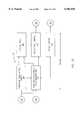
- FIG. 2Ais a functional block diagram of a video processing circuit located, for example, in a base station;
- FIG. 2Bis a functional block diagram illustrating the operation of a scan rate converter
- FIG. 2Cis a block diagram of a transceiver module
- FIG. 2Dis an optical schematic diagram of portions of a transceiver module and a base station
- FIG. 2Eis a more detailed transceiver schematic block diagram, in accordance with a further embodiment of the present invention.
- FIG. 3Ais a schematic front view of an IR module incorporated in a headset, containing components of the IR video interface;
- FIGS. 3B and 3Care top and side schematic views, respectively, of a user wearing an embodiment of a headset including an IR module;
- FIG. 3Dis a functional block diagram of a remote electronics circuit, located for example at a headset;
- FIG. 3Eis a detailed functional block diagram of a headset timing generator
- FIG. 4Ais a cross-sectional optical diagram of a shaping lens, in accordance with an embodiment of the present invention.
- FIG. 4Bis a cross-sectional diagram illustrating the performance of an input lens of a shaping lens
- FIG. 4Cis a split cross-sectional diagram illustrating the overall performance of a shaping lens
- FIG. 4Dis a cross-sectional view of one embodiment of a spacing control mechanism for a shaping lens
- FIG. 4Eis a split cross-sectional view of a shaping lens assembly combined with an IR LED cluster as a modulated beam source;
- FIG. 5Ais a cross-sectional schematic diagram of a collecting lens assembly, in accordance with an embodiment of the present invention.
- FIGS. 5B-5Dare cross-sectional schematic diagrams illustrating the transmission and capture of IR radiation incident from various angles onto a collecting lens assembly.
- FIG. 5Eis a graphic representation of the calculated radiative capture by various combinations of elements of the assembly of FIG. 5A, relative to the radiative capture by an unaided photodetector.
- FIG. 1Ais a schematic view of a surgical environment including an infrared video interface 100 for a head-mounted display, in accordance with the present invention.
- a user 102e.g., a surgeon or assistant, wears a headset 104, containing a remote video display device 140 and a remote electronic circuit 142, including ancillary optical, audio, and electronic apparatus, described in more detail below.
- all of the receiving, processing, audio, and display functions relating to the head-mounted displayare performed within headset 104.
- a remote mobile video bandwidth receiver 146located, e.g., at headset 104, receives a diffusely reflected infrared signal 118 carrying video and/or audio data on a modulated beam of electromagnetic energy.
- a modulated infrared signal 106is transmitted through the atmosphere from a projection lens 108 mounted to a transceiver module 110, which is connected to a base station 112 by a tether 114.
- Projection lens 108is typically a conventional converging optical element, e.g., a convex lens.
- transceiver module 110is integral with base station 112.
- projection lens 108projects modulated IR signal 106 through the atmosphere onto a diffusely reflective target area of the ceiling 116 or (not shown) mounted adjacent ceiling 116.
- Infrared signal 106is scattered through the atmosphere from the diffuse target area as diffusely reflected IR signal 118, a portion of which illuminates headset 104.
- the diffuse target areae.g., ceiling 116
- the diffuse target areahas a lenticular or other well known surface structure, providing a directionally preferred scattering pattern of scattered infrared signal 118.
- headset 104provides a return audio signal back to base station 112.
- a return IR beam 120carries the modulated audio signal at least in part through an atmospheric transmission path, generally retracing the transmission paths of diffusely reflected IR signal 118 and projected infrared signal 106.
- FIG. 1AAlthough a surgical environment is depicted in FIG. 1A, in other embodiments similar configurations including an infrared video interface 100 for a head-mounted display, in accordance with the present invention, are applied to a variety of environments.
- FIG. 1Bis a schematic view of an alternative surgical environment to that of FIG. 1A.
- Transceiver module 110is attached above the working space of users 102, e.g., suspended from ceiling 116 or other elevated support, and is connected with base station 112 by tether 114.
- a shaping lens assembly 130is mounted in transceiver module 110 and is configured to project a shaped infrared beam 132 having a nonuniform pattern, that concentrates shaped IR beam 132 within the volume including the probable location of respective users 102.
- the nonuniform pattern of shaped IR beam 132 of FIG. 1Bprovides greater transmission efficiency and signal to noise ratio (S/N) than the configuration of FIG. 1A, since transmission loss at a diffusely reflecting surface is eliminated.
- infrared video interface 100derive from the requirements of head-mounted video display 140. For some embodiments, these requirements are described in Hebert, U.S. patent application Ser. No. 09/056,934, cited above. In some embodiments, headset 104 does not require a frame memory.
- the display deviceis sequentially illuminated with red, green, and blue light sources, for example LEDs.
- red, green, and blue light sourcesfor example LEDs.
- a user's eyemerges the sequence of colors and creates a perception of full color.
- infrared video interface 100carries each sequential field of red, green, or blue video information as a burst of data. The sequence is repeated at a data rate, such that full motion and full color images are simulated.
- a solid state displayis preferably illuminated at approximately an 80 Hz frame rate (a 240 Hz field rate representing a three-color sequence for each frame) to minimize the amount of flicker perceived by the eye. This is equivalent to one color field each 4.16 msec.
- the NTSC (National Television Standards Committee) video formatprovides a 60 Hz frame rate
- PAL (Phase Alternating Line) video formatprovides a 50 Hz frame rate. Both of these frame rates are too slow to prevent perceived flicker in the solid state display. Because of luminous persistence of phosphors, conventional video displays, e.g. TV screens, are more tolerant of the slower frame rates. Therefore, frame rate conversion is performed in base station 112.
- the method adopted to increase the effective frame rateis cyclical repetition of one or two of the sequential red, green, or blue fields.
- the specific scheme applieddepends on whether the input source conforms with an NTSC or PAL format.
- RGBindicates a new input three-color field sequence (red, green, blue)
- rgbindicates repeated color fields (red, green, blue)
- RGBrGBRgBRGbRGBrGBRgBRGb.
- the insertion of one repeated output color field for each consecutive set of three input color fieldsincreases the perceived frame rate and thereby reduces perceived flicker.
- the repeated color selection and the consecutive input color field setare rotated cyclically, thereby preserving the original color sequence and retaining color fidelity.
- RGBindicates a new input three-color field sequence (red, green, blue), and rgb indicates repeated color fields (red, green, blue)
- RGBrgBRGbrGBRgb RGBrgBRGbrGBRgbindicates repeated color fields
- the insertion of two repeated output color fields for each consecutive set of three input color fieldsincreases the perceived frame rate and thereby reduces perceived flicker.
- the repeated color selections and the consecutive input color field setare rotated cyclically, thereby preserving the original color sequence and retaining color fidelity.
- the total available field time(either 4.16 msec for NTSC or 4.0 msec for PAL) is partitioned into several phases, including: (1) erase display, (2) load display, and (3) illuminate display with an appropriate red, green, or blue LED.
- the display loading timeis selected to be approximately 2 msec for each color field of information.
- each of the 800 ⁇ 600 pixels in the displayis loaded with luminance data, namely, some gradation between black and white.
- infrared video interface 100transmits the equivalent of 240 million pixels per second, roughly a pixel every 4 nsec.
- the IR interface data transport schemecan be described as "burst mode amplitude modulation". Amplitude modulation is preferred to simplify the receiver design.
- the encoding schemecan alternatively utilize pulse modulation without changing the fundamental structure of IR video interface 100. However, receiver circuits would need to convert the pulse modulation back into amplitude modulation to be compatible with a display of the present embodiment.
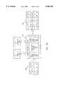
- FIG. 1Cis a graphic representation of a typical burst mode data structure for a solid state video display, in accordance with an embodiment of the present invention.
- signal amplitude 136is shown as a function of time 138.
- Sequential input color fieldsare labeled R, G, and B, followed by a repeated color field labeled r.
- a repetitive sequence of horizontal sync pulses 152provides basic synchronization for the burst mode structure.
- An individual color field 137has a time duration t137, or approximately 4 msec.
- the pixel luminance data 139 within each color fieldis transmitted as a data burst and has a time duration tl39, or approximately 2 msec.
- FIG. 1Dis graphic representation of a typical horizontal line within data burst 139 of FIG. 1C, illustrated on an expanded time scale.
- a typical horizontal sync pulse 152has a substantially rectangular waveform with an amplitude that defines a grey scale between black 154 and white 156.
- Between consecutive horizontal sync pulses 152is one horizontal line of analog pixel data 158, e.g. 800 pixels to a horizontal line.
- the full width t152 of a horizontal sync pulse 152provides a clock basis for data burst timing and has a duration typically equal to that of 32 pixels, which corresponds to approximately 125 nsec.
- the time duration t158 between consecutive horizontal sync pulsesis approximately 3.25 ⁇ sec in the example shown.
- IR video interface 100is adaptable for driving one or two displays.
- half of each color field timeis used for data transfer, and the other half is used for illumination.
- one half of each color field timeis used for data transfer to a first display, and the other half of the time is used for data transfer to the second display.
- First and second displaysare alternately illuminated, such that the illumination occurs for one display while data is transferred to the other display, as described below in more detail.
- IR video interface 100If IR video interface 100 is required to transmit data for two display channels, then each channel can be alternately loaded and illuminated. Thus the interface carries burst mode image data for a first channel during 2 msec, while a second channel is illuminated. Likewise, during the next approximately 2 msec interval, the first channel is illuminated while the interface transmits image data to the second channel.
- This schemecan be described as time division multiplexing (or time-duplexing) with burst mode modulation.
- bandwidthmanifests itself as the ability to resolve fine spatial details, such as the sharp edges of objects. More specifically, the measured bandwidth of a high quality endoscopy video camera is approximately 5.33 MHz for each individual RGB channel.
- An example of such a video camerais the Telecam SL NTSC, sold by Karl Storz Endoscopy, 91 Carpenter Hill Road, Charlton, Mass. 01507.
- the Storz camera bandwidthrepresents approximately 275 horizontal cycles (black-white transitions). This is based on a 60 Hz (525 line) system using a standard 52 ⁇ sec horizontal line time, i.e. (5.33 MHz/52 ⁇ sec) approximately 275 cycles per line.
- the IR video bandwidth required to deliver 275 cycles in one display line time, namely t158 seconds as shown in FIG. 1D,is about 85 MHz, i.e. (275 cycles/3.25 ⁇ sec). Bandwidth calculations for more cycles (higher resolutions) yield about 100 MHz for VGA (320 horizontal cycles) or 125 MHz for SVGA (400 horizontal cycles). In light of these considerations, the infrared interface must support a bandwidth of about 85 MHz to display high quality images from traditional NTSC or PAL sources, and greater than 100 MHz for VGA or SVGA computer generated images.
- Transmitting sequential color fields across IR video interface 100increases the bandwidth requirement, but reduces the complexity of receiver and color decoder circuits, described below in more detail. Additionally, repeating selected color fields in the sequence enables an increase in the rate of updating a display frame, thereby reducing perceived flicker.
- S/Nsignal to noise ratio
- dBdecibels
- a 40 dB S/N ratiorepresents one part of noise in 100 parts of signal, i.e., one percent noise.
- This S/N ratioequates to the EIA standard for "fine quality" broadcast television, which is seen under nearly ideal reception conditions.
- IR video interface 100is designed to meet a higher S/N standard than 40 dB.
- FIG. 1Billustrates transceiver module 110 positioned above users 102 and connected to base station 112 by tether 114. As shown in FIG. 1B, the pattern of IR signal 132 from transceiver module 110 is shaped by shaping lens assembly 130, described below in more detail.
- transceiver module 110is located closer to base station 112, and infrared signal 106 is collimated by projection lens 108 and aimed at a diffuse surface above users 102. This configuration is less efficient than that of FIG. 1B, since IR signal 106 undergoes an extra diffuse reflection.
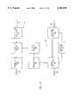
- FIG. 2Ais a functional block diagram of a video processing circuit 160 located, for example, in base station 112.
- An input video signal 161enters at the upper left hand corner and is applied to a video decoder 162.
- Input signal sourcesinclude conventional video sources, such as NTSC, PAL, or SECAM encoded composite sources, e.g., cameras, and 525/625 line component sources such as YUV or S-Video.
- Video decoder 162consists substantially of a conventional Digital Multistandard Color Decoder IC, for example Philips Semiconductors, 811 East Arques Avenue, Sunnyvale, Calif. 94088, Model SAA 7110 Decoder.
- Video decoder 162the NTSC/PAL/SECAM analog video signals are demodulated and converted to digital format luminance and chroma (color) for processing by subsequent circuit modules. Video decoder 162 also provides scaling and offset of various video components such as hue, brightness, and saturation for user preferences.
- Digitally formatted luminance and chroma signals from video decoder 162are applied to a de-interlacer 164, which converts the signals into digital RGB format and then combines the odd and even line fields into a sequential frame format.
- De-interlacer 164consists substantially of a conventional interlaced to sequential frame converter, for example, Genesis Microchip, Inc., 2071 Landings Drive, Mountain View, Calif. 94043, Model gmVLD8 De-Interlacer, with an external pixel buffer RAM memory. Since the odd and even scan fields are separated in time by either 1/50 or 1/60 sec., de-interlacer 164 interpolates between the two fields to minimize tearing of vertical lines when the image is rapidly panned.
- the resulting RBG color pixel dataare applied to a format scalar 166, which interpolates to a higher pixel resolution as required for the display.
- VGA format data640 ⁇ 480 pixels
- SVGA format data800 ⁇ 600 pixels
- Format scaler 166consists substantially of a conventional image scaling and anti-aliasing IC, for example, Genesis Microchip, Inc., 2071 Landings Drive, Mountain View, Calif. 94043, Model gmZ1 Scaler. Scaling algorithms familiar in the art are used to minimize video artifacts created during the scaling process.
- the RGB pixel dataare applied to a scan rate converter 168, which converts the video input frame rates of 50/60 Hz to 83.3/80 Hz to minimize the potential for visible flicker in the display.
- Scan rate converter 168then outputs the frame data in separate red, green, and blue fields.
- Scan rate converter 168is implemented using a Field Programmable Gate Array (FPGA), for example Xilinx, Inc., 2100 Logic Drive, San Jose, Calif., Model 4010 PQ160 FPGA, and a synchronous high speed SDRAM.
- FPGAField Programmable Gate Array
- FIG. 2Bis a functional block diagram illustrating the operation of scan rate converter 168.
- the digital RGB color pixel data 190 from format scaler 166enters scan rate converter 168 from the left and is stored in one of two memory banks 192, 194.
- Each memory bank 192, 194is segmented into red, green, and blue field storage labeled R, G, and B, to facilitate field sequential color imaging.
- Each memory segmentcan hold the red, green, or blue color value, for example an 8-bit quantity, for each of the 480,000 pixels in an SVGA (800 ⁇ 600) field.
- An input pixel store function 196stores video frames alternately in memory bank 192 or 194.
- input pixel store function 196writes data into memory banks 192 and 194
- an output pixel fetch function 198reads data from the respective memory bank 192, 194, that was previously filled with data.
- input pixel store and output pixel fetch functions 196 and 198respectively never overlap their use of the same memory bank 192 or 194. Rather, they alternate memory banks, thereby de-coupling input data from output data.
- a scan rate control logic function 199accepts data at a 50/60 Hz rate supplied by a video source and outputs the data at a higher rate, namely, 83.3/80 Hz.
- Scan rate control logic function 199controls the flow of data in the sequential red, green, and blue fields, instructing output pixel fetch function 198 to insert repeating color fields to convert the effective frame rate.
- headset display 140requires four pixels of data to be loaded during each input cycle.
- output pixel fetch function 198is instructed to read four pixels, e.g., 32 bits, simultaneously and to present these pixel data in a burst format to a pixel data serializer 170.
- Red, green, and blue color field dataare serialized in pixel data serializer 170 (see FIG. 2A) into a stream suitable for transmission over a wireless link.
- pixel data serializer 170inserts video synchronization information to define horizontal, vertical, and color syncs.
- Pixel data serializer 170converts the parallel digital pixel color data into amplitude modulated signals using conventional digital to analog converters (DAC's). It then outputs the analog signals, e.g., four pixel values, into a high speed serial data stream suitable for transmission over the wireless (serial) link.
- Conventional sample-and-hold amplifiersare used to delay the analog signals for conversion to a serial analog data stream, as described above in connection with FIG. 1C.
- an input audio signal 171 from a microphone or other conventional sourceenters an input amplifier IC 172 with level control and high frequency boost to improve overall S/N ratio.
- the audio signalis then applied to an FM audio modulator 174, typically a voltage controlled oscillator (VCO), which converts the amplitude modulated signal to narrow band frequency modulated signal on a carrier.
- VCOvoltage controlled oscillator
- the FM modulated signalis bandpass limited by a low pass filter 176 to remove any unwanted high frequency signals generated by the FM modulation process, and is then combined with video data from pixel data serializer 170 in a laser diode driver 178, incorporating a high speed FET current amplifier.
- the audio signalWhen combined, the audio signal is in the lower frequency portion of the IR modulation spectrum (frequency division multiplexing), and is easily recovered from the video using bandpass filters.
- the audio FMis then conventionally converted to a normal analog audio signal, e.g., for headphones, using an FM discriminator.
- the combined serial video data and optional modulated audio data from laser diode driver 178modulate an infrared laser diode 180, selected for its high frequency modulation capability, which converts the signal into a modulated IR beam.
- Laser diode driver 178consists substantially of operational amplifier (OpAmp) IC's that drive a high speed FET amplifier, which in turn controls the output of commercial IR laser diode 180.
- Infrared light 240 from infrared laser diode 180is shaped by lenses and focused into one end of an output optical fiber cable for transport to transceiver module 110, described below in more detail.
- a return audio signal 151 from headset 104(transmitted through an incoming optical fiber cable) is applied to a photodiode and preamplifier 156, which converts the modulated optical signal to a low level modulated electrical signal, amplifies the low level signal, passband limits it using a conventional filter, and applies it to an FM audio demodulator (discriminator) 157, which recovers the audio signal.
- the audio signalis frequency conditioned to improve the signal to noise ratio at high frequency and to restore the overall audio fidelity of the signal.
- the audio signalis processed by a line driver IC amplifier with level control circuits 159 for output coupling to conventional audio output equipment (not shown).
- FIG. 2Cis a block diagram of transceiver module 110, which is used to distribute (broadcast) combined audio and video signals from base station 112 to headset 104.
- Transceiver module 110also serves as a collection and relay module for optional audio signals returning from headset 104.
- transceiver module 110is located above and proximate to the area where headset 104 is used. This placement optimizes the signal distribution and provides the best image quality by minimizing reflections along the signal path.
- Transceiver module 110can be implemented with either a single or a dual optical fiber tether from base station 112. For the present discussion, a dual fiber implementation is described. However, the respective functions of transceiver module 110 and base station 112 are substantially unchanged relative to the single optical fiber implementation.
- FIG. 2Dis an optical schematic diagram of portions of transceiver module 110 and base station 112.
- Modulated IR beam 240carries combined video and optional audio infrared signals from base station 112 through an optical fiber to a diverging input lens 414 of shaping lens assembly 130.
- Input lens 414spreads modulated IR beam 240 into a diverging pattern, a portion of which is collected by a photodetector 242, and the bulk of which is directed to a converging output lens 416 of shaping lens assembly 130 for transmission in a shaped IR signal pattern 132 toward remote receiver 146, e.g., headset 104.
- a shaping adjustment mechanism 244sets the spacing between input/output lenses 414 and 416 respectively. If lenses 414, 416 are closely spaced, then shaped IR signal 132 is spread more horizontally.
- Shaping adjustment mechanism 244 as shown in FIG. 2Callows adjustment of the height of transceiver module 110, e.g., above an operating theater, and corresponding control of the shape of IR beam pattern 132 to cover an area where headset 104 is located.
- a return modulated audio IR signal 120 from headset 104is collected by a collecting lens and light cone 252 in transceiver module 110, and the collected light directed to a photodiode and amplifier 254.
- Photodiode and amplifier 254convert and amplify the optical signal to produce an electric audio signal, which drives an IR LED 256.
- IR LED 256re-transmits the amplified audio IR signal 151 through an optical fiber tether to photodiode and preamplifier 156 in base station 112.
- an amber or other visible wavelength LEDcan substitute for IR LED 256.
- Photodetector 242generates a photoelectric voltage, which is applied to a DC-to-DC converter 246 to provide electrical power required to operate photodiode and amplifier 254 and to drive LED 256.
- collecting lens and light cone 252are substantially coaxial relative to the elements of shaping lens assembly 130.
- shaping lens assembly 130can be replaced in transceiver module 110 by projection lens 108, for example a conventional converging optical element.
- transceiver module 110is connected to base station 112 by an electrically conductive coaxial cable 182, shown schematically in FIGS. 2A and 2D by dashed lines with arrows.
- the electronics and optics of base station 112are redistributed, for example all optical components, LEDs, and photodetectors are included in transceiver module 110, as shown enclosed by dashed outlines in FIGS. 2A and 2D.
- the overall functionremains as described above, namely, to deliver the modulated IR energy in a pattern that optimizes the energy of IR signal 106 available to headset 104.
- infrared laser diode 180can alternatively be replaced by one or more high-frequency infrared LED's, for example, Siemens Microelectronics, Inc., 10950 North Tantau Avenue, Cupertino, Calif. 95014 Model SFH4592.
- Siemens Microelectronics, Inc.10950 North Tantau Avenue, Cupertino, Calif. 95014 Model SFH4592.
- FIG. 2Eis a more detailed transceiver schematic block diagram, in accordance with a further embodiment of the present invention.
- Transceiver circuit 210is connected with base station 112 through electrically conducting coaxial cable 182, which carries respective video signals 270, audio signals 151, and DC electrical power 272.
- DC power 272 from coaxial cable 182is filtered from audio and video signals by a low pass filter and power supply 260, which provides power for the active elements of transceiver circuit 210.
- Video signal 270 from coaxial cable 182is filtered through a high pass filter 262 and is applied through a DC level restore module 266 to LED drivers 278, which drive an IR LED cluster 280.
- the modulated IR LED beamis shaped by an alternative single-element shaping lens 284 to produce shaped IR beam 132.
- An alternative shaping lens assemblyincludes LED cluster 280, shaping lens 284, and a shaping adjustment mechanism 282, similar to shaping adjustment mechanism 244, which controls the shape of IR beam 132 by adjusting the separation between shaping lens 284 and LED cluster 280.
- Optional return audio signal on return IR beam 120is transmitted through collecting lens and lightcone 252 onto photodiode and amplifier 254 where it is converted into an electrical signal.
- the audio electrical signal from photodiode and amplifier 254is amplified by a line driver 258 and is then filtered through a bandpass filter 264 prior to transmission as audio carrier signal 151 through coaxial cable 182 to base station 112.
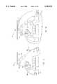
- FIG. 3Ais a schematic front view of an IR module 300 containing components of IR video interface 100 incorporated in headset 104.
- FIGS. 3B and 3Care top and side schematic views, respectively, of a user wearing an embodiment of headset 104 including IR module 300.
- IR module 300is mounted away from the user's peripheral vision field and above the LCD and associated display optics (see Hebert, cited above), thereby providing a substantially unobstructed wide angle reception path to the ceiling or to an overhead transmitting lens.
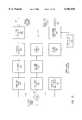
- FIG. 3Dis a functional block diagram of remote electronic circuit 142, located for example at headset 104.
- the combined video and optional audio low level electronic signals from IR photodetector 304enter adjacent to the middle left hand side of FIG. 3D.
- the signalsare applied to preamplifier/AGC/audio carrier filter module 305 where the signal is amplified and level adjusted by a conventional automatic gain control (AGC) circuit.
- AGCautomatic gain control
- the optional audio carrier portionis separated using a conventional bandpass filter (frequency domain demultiplexing) and applied to an FM demodulator 324, which recovers the audio signal in a manner similar to return audio demodulator 157.
- the recovered audio signalis then applied to a headphone amplifier 326 configured for driving a conventional dynamic headphone speaker element 328.
- the separated video signal portioncontinues into a video processing module 330, where gamma correction and black level control are performed using conventional techniques.
- Gamma correctioncompensates for the different response of headset display 140 relative to the response of a traditional phosphor based CRT.
- Gamma correctionadjusts the video signal, such that headset display 140 exhibits a more accurate range of brightness than would be realized without gamma correction.
- Black level controlrestores the correct baseline DC voltage to the video waveform.
- the output from signal processing module 305is further separated at a sync stripper module 332 into synchronization components, which generate timing signals.
- the synchronization componentsare applied to a headset timing generator 334, which generates signals that control display and LED illumination sub-systems.
- FIG. 3Eis a detailed functional block diagram of headset timing generator 334, which is implemented with a field programmable gate array (FPGA), similar to that described in connection with FIG. 2A.
- Composite sync components from sync stripper module 332, including horizontal start pulses and field start pulses,are applied to headset timing generator 334.
- a horizontal timer and pixel counter module 350locates the beginnings of lines and counts the pixels within each line, for example, 800 active pixels per line of display 140 plus inactive pixels used for timing and control.
- a timing windowis generated at the expected field start pulse time (with respect to the horizontal start pulse), that is used by field start detection and color identification module 354 to detect a start of field condition.
- a vertical timing module 356When start of field is detected, a vertical timing module 356 is reset to zero and commences counting lines in a field, for example, 600 lines. During the vertical timing interval, a small number of non-video lines from video processor module 330 are encoded with color identifiers. These color identifiers are detected by field start detection and color identification module 354 and are used by a RGB LED control module 352 to synchronize display LEDs 340 with the appropriate color fields. Vertical timing pulses from vertical timing module 356 and color IDs from field start detection and color identification module 354 are used by display sync control module 358 to generate signals that control the operation of a display drive module 336 and microdisplay 140.
- headset timing generator 334includes control signals for display drive module 336 and control signals for display LEDs 340.
- display 140cycles through erase, load, and illuminate phases.
- Timing generator 334is responsible for correctly sequencing these phases.
- Display drive module 336demultiplexes the video pixels, converting serial pixel analog voltages to parallel analog voltages suitable for driving a display.
- Microdisplay 140 and associated drivers 336receive video data from video processor module 330 and control signals from headset timing generator 334. These are used to load the sequential color field data, which are stored in memory cells internal to microdisplay 140. After the data are loaded and stabilized, a selected red, green, or blue LED 340 is pulsed to illuminate display 140 with the correct color.
- the overall brightness of display 140is adjusted using an optional ambient light detector circuit 342. Light from the room is measured by a photodetector 308 to provide a control signal to boost or reduce the average brightness level of LEDs 340.
- An optional return audio signalis generated by a microphone 360 mounted at headset 104, and is processed by audio electronics including a microphone amplifier 361 and an audio FM modulator 362, in a manner similar to that described in connection with FIG. 2A.
- the processed return audio signaldrives an infrared LED 306, thereby generating modulated return IR beam 120, which is transmitted through the atmosphere to transceiver module 110, where it is collected and relayed to base station 112.
- An alternative return audio implementationemploys burst mode multiplexing during periods when there is no video transmission.
- this schemerequires more complex circuitry and competes with video data for bandwidth.
- FIG. 4Ais a cross-sectional view of shaping lens assembly 130, in accordance with an embodiment of the present invention.
- shaping lens assembly 130 as shown in FIG. 4Ais absent collecting lens and light cone 252 pictured coaxially in FIG. 2D.
- shaping lens assembly 130is nominally rotationally symmetric about a symmetry axis 410, it can alternatively be designed to provide an azimuthally varying radiation pattern about axis 410.
- the present embodimentshows modulated IR beam 240 delivered through an optical fiber extending from laser diode source 180 (see FIG. 2D).
- Shaping lens assembly 130includes an input lens 414, having a divergent conic shape; and an output lens 416, having a convergent conic shape.
- the hollow conical input surfaces of input lens 414 and output lens 416are oriented at approximately 45 degrees relative to axis 410.
- the shape of the output surface 418 of input lens 414is flat.
- the shape of the output surface 420 of output lens 416is approximately hemispherical.
- Input lens 414 and output lens 416are typically made of optically transmissive polymeric material with high optical quality in the visible and near infrared wavelength range extending from approximately 700 nm to approximately 1,100 nm. Suitable materials for input lens 414 and output lens 416 include polymethyl methacrylate and polycarbonate.
- the embodiment of shaping lens assembly 130 as described in connection with FIG. 4Ais aspheric.
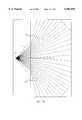
- FIG. 4Bis a cross-sectional schematic diagram illustrating the performance of input lens 414 accepting IR energy from modulated IR beam 240 and separating this input energy into conical side lobes 422 with energy densities maximized approximately 45 degrees off-axis.
- This output energy patternis typically rotationally symmetric, as described above.
- FIG. 4Cis a split cross-sectional diagram illustrating the adjustable orientation of the output radiation pattern from shaping lens assembly 130.
- Input lens 414 and output lens 416are aligned and adjustably separated along their common axis 410.
- the angular spread of the refracted output energy density patternis controlled by the separation between input and output lenses 414 and 416.
- the right portion of FIG. 4Cshows a wide angular spread of the output energy density pattern resulting from a close separation between input lens 414 and output lens 416.
- the left portion of FIG. 4Cshows a narrower angular spread of the output energy density pattern resulting from a larger separation between input lens 414 and output lens 416. Higher densities occur in side lobes away from axis 410, as indicated by the closer spacings between lines 424.
- FIG. 4Dis a cross-sectional view of one embodiment of a spacing control mechanism 430 for adjusting the separation between input lens 414 and output lens 416 along common axis 410.
- the overall assembly of shaping lens assembly 130is supported by an outer flange 432, which is fastened to a plate or bulkhead (not shown).
- a hollow threaded tube 434 attached to outer flange 432 and substantially coaxial with axis 410supports input lens 414 at a specified distance from modulated IR beam 240.
- a nut 436 containing output lens 416engages hollow threaded tube 434, such that the separation between input lens 414 and output lens 416 along axis 410 is adjusted by rotating nut 436 about axis 410 on hollow threaded tube 434.
- FIG. 4Dis split, the left portion showing maximum separation and the right portion showing minimum separation between input lens 414 and output lens 416.
- An inner flange 438 around hollow threaded tube 434prevents nut 436 from rotating off the end of hollow threaded tube 434.
- the more downward radiation pattern shown in the left portion of FIG. 4Cis more appropriate for a transceiver module 110 located at a higher level (e.g., toward ceiling 116), whereas the more horizontally spread radiation pattern shown in the right portion of FIG. 4C is more appropriate for a transceiver module 110 located at a lower level, e.g., below a surgical lighting system (typically 1.8 meters to 3.0 meters above floor level).
- the angular spread of the IR output energy patterncan be controlled by varying the distance between modulated IR beam 240 and input lens 414.
- FIG. 4Eis a split cross-sectional view of an alternative shaping lens assembly 450 combined with an IR LED cluster as a modulated beam source (see also FIG. 2E).
- Shaping lens assembly 450includes a shaping control mechanism 282 similar in structure and operation to shaping control mechanism 430 illustrated in FIG. 4D.
- An IR LED cluster 280is attached to an alignment fixture 456 on a printed circuit card 452 mounted to hollow threaded tube 434.
- IR LED cluster 280is driven by an electrical signal through a coaxial cable 454.
- a single-element shaping lens 284, configured substantially the same as converging output lens 416,is mounted onto rotating nut 436.
- FIG. 5Ais a cross-sectional schematic diagram of collecting lens assembly 302 at headset 104, in accordance with an embodiment of the present invention.
- Collecting lens assembly 302is configured to achieve both a large angular field of view 510, e.g., to accommodate head motion, and a large entrance pupil to receive maximum energy from IR signal 118 or 132.
- collecting lens assembly 302is nominally rotationally symmetric about a symmetry axis 512, it can alternatively be configured to provide an azimuthally variable detectivity pattern about axis 512.
- Photodetector 304can be any photosensitive device having the optical and electronic responses required for the application, but is shown in FIG. 5A as a silicon device selected for its high frequency electronic performance and for high sensitivity to infrared radiation over a wavelength region of approximately 700 nm to approximately 1100 nm.
- Photodetector 304is optically cemented to one end of an inner light cone 514, which is solid and has concentric ribs 516 on its outer walls 515. Outer walls 515 are oriented, for example, at a 45-degree angle relative to symmetry axis 512. Optical cementing avoids total internal reflection losses at the detector-lens interface at steep angles of incidence. Concentric ribs 516 diffusely reflect IR radiation back into collecting lens assembly 302, that would otherwise escape laterally.
- a wide-angle collecting lens 518having a numerical aperture of approximately f/0.8, which provides a large entrance pupil.
- the embodiment of wide-angle collecting lens 518 as shown in FIG. 5Ais aspheric.
- Wide-angle collecting lens 518 and inner light coneare typically made of an optically transmissive polymeric material (for example ULTEM® grade polycarbonate manufactured by the General Electric Company), and can be fabricated as a combined monolithic element.
- Disposed coaxially around wide-angle collecting lens 518 and inner light cone 514is a hollow outer conic cavity 520, having polished inner walls 521, which reflects IR signal 118 or 132 into wide-angle collecting lens 518 and inner light cone 514 over a wider aperture.
- Inner walls 521are preferably metallic, typically aluminum for high reflectivity and durability. Inner walls 521 are oriented, for example, at an angle of approximately 19 degrees to approximately 27 degrees relative to symmetry axis 512.
- An optical filter 522such as KODAK WRATTEN® No. 87B, covers the entrance aperture of outer conic cavity 520. Alternatively, an optical filtering material is incorporated into the material of wide-angle collecting lens 518. Collecting lens and light cone 252, shown in FIG. 2D, has substantially the same structure as collecting lens assembly 302.
- FIGS. 5B-5Dare cross-sectional schematic diagrams illustrating the transmission and capture of IR radiation incident from various angles onto collecting lens assembly 302.
- FIG. 5Bshows the case of radiation 530 incident normal to the plane of photodetector 304. This radiation is captured efficiently by wide-angle lens 518 alone.
- FIG. 5Cshows the case of radiation 532 incident at a 30-degree angle from normal, which is efficiently captured by wide-angle lens 518 and inner light cone 514 cooperatively.
- FIG. 5Dshows the case of radiation 534 incident at 40-degree angle from normal.
- outer conic cavity 520reflects radiation into wide-angle lens 518 that would otherwise be lost. This reclaimed radiation is then efficiently captured by wide-angle lens 518 and inner light cone 514 cooperatively.
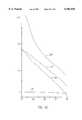
- FIG. 5Eis a graphic representation of the calculated radiative capture by various elements of collecting lens assembly 302, relative to the radiative capture by photodetector 304 absent the other elements of collecting lens assembly 302.
- Relative radiative captureis shown along the vertical axis, and off-axis angle of incidence relative to symmetry axis 512 is shown along the horizontal axis.
- the baseline radiative capture of identically 1.0 by unaided photodetector 304is shown as curve 540.
- Curve 542shows the combined relative radiative capture by photodetector 304 and wide-angle collecting lens 518.
- Curve 544shows the combined relative radiative capture by photodetector 304, wide-angle collecting lens 518, and inner light cone 514.
- Curve 546shows the combined relative radiative capture by entire collecting lens assembly 302, including photodetector 304, wide-angle collecting lens 518, inner light cone 514, and outer conic cavity 520. As shown in FIG. 5C, the radiative capture by complete collecting lens assembly 302 relative to unaided photodetector 304 exceeds a factor of 15 on-axis and approximates a factor of four at a 40-degree angle off-axis.
- a tether 124(shown dashed) is connected directly from base station 112 to remote electronic circuit 142 at headset 104, where it delivers the combined audio/visual signal.
- Tether 124can contain either a single or dual optical fiber cable, such that a second optical fiber transmits return IR signal 120.
- tether 124contains a bi-directional, electrically conducting coaxial cable. This configuration greatly simplifies IR video interface 100 by eliminating most components of transceiver module 110 and collecting lens assembly 302.
- the coaxial cable implementationadditionally eliminates all optical and optoelectronic components. It also improves signal to noise performance at reduced power.
- the direct tether connection to headset 104adversely restricts the freedom of motion of user 102.
Landscapes
- Physics & Mathematics (AREA)
- General Physics & Mathematics (AREA)
- Optics & Photonics (AREA)
- Electromagnetism (AREA)
- Engineering & Computer Science (AREA)
- Computer Networks & Wireless Communication (AREA)
- Signal Processing (AREA)
Abstract
Description
Claims (78)
Priority Applications (4)
| Application Number | Priority Date | Filing Date | Title |
|---|---|---|---|
| US09/305,092US6101038A (en) | 1999-05-03 | 1999-05-03 | Infrared audio/video interface for head-mounted display |
| AU47152/00AAU4715200A (en) | 1999-05-03 | 2000-05-03 | Infrared audio/video interface for head-mounted display |
| PCT/US2000/040081WO2000066023A1 (en) | 1999-05-03 | 2000-05-03 | Infrared audio/video interface for head-mounted display |
| EP00929000AEP1237491A1 (en) | 1999-05-03 | 2000-05-03 | Infrared audio/video interface for head-mounted display |
Applications Claiming Priority (1)
| Application Number | Priority Date | Filing Date | Title |
|---|---|---|---|
| US09/305,092US6101038A (en) | 1999-05-03 | 1999-05-03 | Infrared audio/video interface for head-mounted display |
Publications (1)
| Publication Number | Publication Date |
|---|---|
| US6101038Atrue US6101038A (en) | 2000-08-08 |
Family
ID=23179297
Family Applications (1)
| Application Number | Title | Priority Date | Filing Date |
|---|---|---|---|
| US09/305,092Expired - LifetimeUS6101038A (en) | 1999-05-03 | 1999-05-03 | Infrared audio/video interface for head-mounted display |
Country Status (4)
| Country | Link |
|---|---|
| US (1) | US6101038A (en) |
| EP (1) | EP1237491A1 (en) |
| AU (1) | AU4715200A (en) |
| WO (1) | WO2000066023A1 (en) |
Cited By (70)
| Publication number | Priority date | Publication date | Assignee | Title |
|---|---|---|---|---|
| US20020130821A1 (en)* | 2001-03-16 | 2002-09-19 | Barry Bronson | Method and apparatus for displaying images |
| US20020191104A1 (en)* | 2001-03-26 | 2002-12-19 | Mega Chips Corporation | Image conversion device, image conversion method and data conversion circuit as well as digital camera |
| WO2002054959A3 (en)* | 2001-01-03 | 2003-02-20 | Optimize Incorporated | Infrared audio-video interface for head-mounted display |
| WO2003042968A1 (en)* | 2001-11-14 | 2003-05-22 | The Henry M. Jackson Foundation | Method and system for presenting real time physiological information through a head mounted display |
| US6603397B2 (en) | 2001-03-14 | 2003-08-05 | Hewlett-Packard Development Company, L.P. | Control of emissions by devices in sensitive environments |
| US6635879B2 (en)* | 2001-02-28 | 2003-10-21 | Anzai Medical Kabushiki Kaisha | Apparatus for and method of detecting radiation source |
| US20040004584A1 (en)* | 2002-03-20 | 2004-01-08 | Raymond Hebert | Head-mounted viewing system for single electronic displays using biocular lens with binocular folding mirrors |
| EP1380936A1 (en)* | 2002-07-10 | 2004-01-14 | Hewlett-Packard Development Company, L.P. | Active display system and method with optical addressing |
| US6683590B1 (en)* | 1998-03-20 | 2004-01-27 | The University Of Hong Kong | Tricolor LED display system having audio output |
| US6741336B2 (en)* | 2000-06-03 | 2004-05-25 | Bundesruckerai Gmbh | Sensor for authenticity identification of signets on documents |
| US20040111030A1 (en)* | 2000-01-19 | 2004-06-10 | Zeman Herbert D. | Imaging system using diffuse infrared light |
| US6903706B1 (en)* | 2002-03-20 | 2005-06-07 | Matrox Graphics Inc. | Method and apparatus for multi-display of digital visual interfaces |
| US20050162339A1 (en)* | 2002-04-03 | 2005-07-28 | Schem N. Z. Limited | Remote monitoring apparatus |
| US20050254256A1 (en)* | 2004-05-14 | 2005-11-17 | Siemens Aktiengesellschaft | Illumination device and medical imaging and examination device having an illumination device |
| US7008074B1 (en) | 2002-12-10 | 2006-03-07 | Halm Gary V | Hands-free controlled light operation |
| US20060122515A1 (en)* | 2000-01-19 | 2006-06-08 | Luminetx Corporation | Projection of subsurface structure onto an object's surface |
| US7081870B2 (en) | 2001-05-09 | 2006-07-25 | Hewlett-Packard Development Company, L.P. | Wearable display and method of displaying images using a wearable display |
| US7170677B1 (en) | 2002-01-25 | 2007-01-30 | Everest Vit | Stereo-measurement borescope with 3-D viewing |
| USD541922S1 (en) | 2005-03-31 | 2007-05-01 | S.C. Johnson & Son, Inc. | Diffuser |
| USD542400S1 (en) | 2005-03-31 | 2007-05-08 | S.C. Johnson & Son, Inc. | Diffuser |
| US7281811B2 (en) | 2005-03-31 | 2007-10-16 | S. C. Johnson & Son, Inc. | Multi-clarity lenses |
| US7313246B2 (en) | 2001-10-06 | 2007-12-25 | Stryker Corporation | Information system using eyewear for communication |
| US7327919B1 (en)* | 2004-06-25 | 2008-02-05 | Jimmy Ko | Fiber optic audio cable |
| US20080276178A1 (en)* | 2007-05-04 | 2008-11-06 | Apple Inc. | Adjusting media display in a personal display system based on perspective |
| US20090097859A1 (en)* | 2007-10-12 | 2009-04-16 | Hon Hai Precision Industry Co., Ltd. | Emitter, converter, and display system using same |
| US7589340B2 (en) | 2005-03-31 | 2009-09-15 | S.C. Johnson & Son, Inc. | System for detecting a container or contents of the container |
| US7643734B2 (en) | 2005-03-31 | 2010-01-05 | S.C. Johnson & Son, Inc. | Bottle eject mechanism |
| US7687744B2 (en) | 2002-05-13 | 2010-03-30 | S.C. Johnson & Son, Inc. | Coordinated emission of fragrance, light, and sound |
| US20100079356A1 (en)* | 2008-09-30 | 2010-04-01 | Apple Inc. | Head-mounted display apparatus for retaining a portable electronic device with display |
| US7824052B1 (en) | 2007-03-16 | 2010-11-02 | Halm Gary V | Foot controlled light operation |
| US20100315429A1 (en)* | 2009-06-11 | 2010-12-16 | Rykowski Ronald F | Visual display measurement and calibration systems and associated methods |
| US7932482B2 (en) | 2003-02-07 | 2011-04-26 | S.C. Johnson & Son, Inc. | Diffuser with light emitting diode nightlight |
| US20110234484A1 (en)* | 2010-03-29 | 2011-09-29 | Olympus Corporation | Operation input unit and manipulator system |
| USD648882S1 (en) | 2010-11-02 | 2011-11-15 | Halm Gary V | Combination light and IR detector |
| US8179604B1 (en) | 2011-07-13 | 2012-05-15 | Google Inc. | Wearable marker for passive interaction |
| EP1961209A4 (en)* | 2005-12-16 | 2012-09-05 | Infra Com Ltd | Wireless infrared multimedia system |
| US8405489B1 (en)* | 2010-06-28 | 2013-03-26 | Gary V. Halm | Master subservient light operation |
| US8467133B2 (en) | 2010-02-28 | 2013-06-18 | Osterhout Group, Inc. | See-through display with an optical assembly including a wedge-shaped illumination system |
| US8472120B2 (en) | 2010-02-28 | 2013-06-25 | Osterhout Group, Inc. | See-through near-eye display glasses with a small scale image source |
| US8477425B2 (en) | 2010-02-28 | 2013-07-02 | Osterhout Group, Inc. | See-through near-eye display glasses including a partially reflective, partially transmitting optical element |
| US8482859B2 (en) | 2010-02-28 | 2013-07-09 | Osterhout Group, Inc. | See-through near-eye display glasses wherein image light is transmitted to and reflected from an optically flat film |
| US8488246B2 (en) | 2010-02-28 | 2013-07-16 | Osterhout Group, Inc. | See-through near-eye display glasses including a curved polarizing film in the image source, a partially reflective, partially transmitting optical element and an optically flat film |
| US8605008B1 (en)* | 2007-05-04 | 2013-12-10 | Apple Inc. | Head-mounted display |
| US8814691B2 (en) | 2010-02-28 | 2014-08-26 | Microsoft Corporation | System and method for social networking gaming with an augmented reality |
| WO2015073335A1 (en)* | 2013-11-18 | 2015-05-21 | Gyrus Acmi, Inc. (D.B.A. Olympus Surgical Technologies America) | Line of sight wireless endoscopy |
| US9091851B2 (en) | 2010-02-28 | 2015-07-28 | Microsoft Technology Licensing, Llc | Light control in head mounted displays |
| US9097890B2 (en) | 2010-02-28 | 2015-08-04 | Microsoft Technology Licensing, Llc | Grating in a light transmissive illumination system for see-through near-eye display glasses |
| US9097891B2 (en) | 2010-02-28 | 2015-08-04 | Microsoft Technology Licensing, Llc | See-through near-eye display glasses including an auto-brightness control for the display brightness based on the brightness in the environment |
| US9128281B2 (en) | 2010-09-14 | 2015-09-08 | Microsoft Technology Licensing, Llc | Eyepiece with uniformly illuminated reflective display |
| US9129295B2 (en) | 2010-02-28 | 2015-09-08 | Microsoft Technology Licensing, Llc | See-through near-eye display glasses with a fast response photochromic film system for quick transition from dark to clear |
| US9134534B2 (en) | 2010-02-28 | 2015-09-15 | Microsoft Technology Licensing, Llc | See-through near-eye display glasses including a modular image source |
| US9182596B2 (en) | 2010-02-28 | 2015-11-10 | Microsoft Technology Licensing, Llc | See-through near-eye display glasses with the optical assembly including absorptive polarizers or anti-reflective coatings to reduce stray light |
| US20150346700A1 (en)* | 2014-06-02 | 2015-12-03 | Rovio Entertainment Ltd | Control of a computer program |
| US9223134B2 (en) | 2010-02-28 | 2015-12-29 | Microsoft Technology Licensing, Llc | Optical imperfections in a light transmissive illumination system for see-through near-eye display glasses |
| US9229227B2 (en) | 2010-02-28 | 2016-01-05 | Microsoft Technology Licensing, Llc | See-through near-eye display glasses with a light transmissive wedge shaped illumination system |
| US9285589B2 (en) | 2010-02-28 | 2016-03-15 | Microsoft Technology Licensing, Llc | AR glasses with event and sensor triggered control of AR eyepiece applications |
| US9298283B1 (en) | 2015-09-10 | 2016-03-29 | Connectivity Labs Inc. | Sedentary virtual reality method and systems |
| US9341843B2 (en) | 2010-02-28 | 2016-05-17 | Microsoft Technology Licensing, Llc | See-through near-eye display glasses with a small scale image source |
| US9366862B2 (en) | 2010-02-28 | 2016-06-14 | Microsoft Technology Licensing, Llc | System and method for delivering content to a group of see-through near eye display eyepieces |
| FR3045844A1 (en)* | 2015-12-22 | 2017-06-23 | Inst Mines Telecom | WIRELESS OPTICAL LINK SYSTEM FOR TRANSMITTING VERY HIGH-SPEED DATA IN A WAY OF ROAMING |
| US9699281B2 (en) | 2009-02-27 | 2017-07-04 | Eyecam, Inc. | Headset-based telecommunications platform |
| US9759917B2 (en) | 2010-02-28 | 2017-09-12 | Microsoft Technology Licensing, Llc | AR glasses with event and sensor triggered AR eyepiece interface to external devices |
| US10120194B2 (en) | 2016-01-22 | 2018-11-06 | Corning Incorporated | Wide field personal display |
| US10180572B2 (en) | 2010-02-28 | 2019-01-15 | Microsoft Technology Licensing, Llc | AR glasses with event and user action control of external applications |
| WO2019099309A1 (en)* | 2017-11-17 | 2019-05-23 | Microsoft Technology Licensing, Llc | Mixed reality offload using free space optics |
| US20190278091A1 (en)* | 2010-10-04 | 2019-09-12 | Gerard Dirk Smits | System and method for 3-d projection and enhancements for interactivity |
| US10492873B2 (en)* | 2016-10-25 | 2019-12-03 | Novartis Ag | Medical spatial orientation system |
| US10539787B2 (en) | 2010-02-28 | 2020-01-21 | Microsoft Technology Licensing, Llc | Head-worn adaptive display |
| US10860100B2 (en) | 2010-02-28 | 2020-12-08 | Microsoft Technology Licensing, Llc | AR glasses with predictive control of external device based on event input |
| US10976551B2 (en) | 2017-08-30 | 2021-04-13 | Corning Incorporated | Wide field personal display device |
Citations (14)
| Publication number | Priority date | Publication date | Assignee | Title |
|---|---|---|---|---|
| US3674925A (en)* | 1970-12-03 | 1972-07-04 | Us Navy | Cable-less television system |
| US4577937A (en)* | 1984-10-01 | 1986-03-25 | Clegg John E | Conical beam concentrator |
| US4577938A (en)* | 1984-09-17 | 1986-03-25 | Clegg John E | Conical beam concentrator |
| US4679912A (en)* | 1982-11-10 | 1987-07-14 | U.S. Philips Corporation | Binocular eyepiece |
| US5005213A (en)* | 1986-07-10 | 1991-04-02 | Varo, Inc. | Head mounted video display and remote camera system |
| US5285318A (en)* | 1992-06-22 | 1994-02-08 | Nioptics Corporation | Illumination system having an aspherical lens |
| US5438366A (en)* | 1993-03-31 | 1995-08-01 | Eastman Kodak Company | Aspherical blur filter for reducing artifacts in imaging apparatus |
| US5452733A (en)* | 1993-02-22 | 1995-09-26 | Stanford Surgical Technologies, Inc. | Methods for performing thoracoscopic coronary artery bypass |
| US5612710A (en)* | 1995-08-22 | 1997-03-18 | Fairtron Corporation | Real time low cost, large scale array 65K color display using lamps |
| US5619373A (en)* | 1995-06-07 | 1997-04-08 | Hasbro, Inc. | Optical system for a head mounted display |
| US5695504A (en)* | 1995-02-24 | 1997-12-09 | Heartport, Inc. | Devices and methods for performing a vascular anastomosis |
| US5818419A (en)* | 1995-10-31 | 1998-10-06 | Fujitsu Limited | Display device and method for driving the same |
| US5909322A (en)* | 1997-11-05 | 1999-06-01 | Eastman Kodak Company | Magnifier lens |
| US5982343A (en)* | 1903-11-29 | 1999-11-09 | Olympus Optical Co., Ltd. | Visual display apparatus |
Family Cites Families (9)
| Publication number | Priority date | Publication date | Assignee | Title |
|---|---|---|---|---|
| US4322124A (en)* | 1980-05-05 | 1982-03-30 | Honeywell Inc. | Low cost wide field of view infrared sensor |
| US4491900A (en)* | 1982-09-27 | 1985-01-01 | Savage John Jun | Lens and mount for use with electromagnetic wave source |
| US4786966A (en)* | 1986-07-10 | 1988-11-22 | Varo, Inc. | Head mounted video display and remote camera system |
| US5003300A (en)* | 1987-07-27 | 1991-03-26 | Reflection Technology, Inc. | Head mounted display for miniature video display system |
| JPS6467095A (en)* | 1987-09-07 | 1989-03-13 | Sharp Kk | Wireless transmitter for 3d vision system |
| US4977618A (en)* | 1988-04-21 | 1990-12-11 | Photonics Corporation | Infrared data communications |
| US5308985A (en)* | 1991-10-31 | 1994-05-03 | Intelectron Products Company | Wide-angle passive infrared radiation detector |
| JPH05183514A (en)* | 1991-12-27 | 1993-07-23 | Mitsubishi Electric Corp | Optical space transmission device |
| JPH10257529A (en)* | 1997-03-11 | 1998-09-25 | Sony Corp | Image display device and method |
- 1999
- 1999-05-03USUS09/305,092patent/US6101038A/ennot_activeExpired - Lifetime
- 2000
- 2000-05-03EPEP00929000Apatent/EP1237491A1/ennot_activeWithdrawn
- 2000-05-03AUAU47152/00Apatent/AU4715200A/ennot_activeAbandoned
- 2000-05-03WOPCT/US2000/040081patent/WO2000066023A1/ennot_activeApplication Discontinuation
Patent Citations (14)
| Publication number | Priority date | Publication date | Assignee | Title |
|---|---|---|---|---|
| US5982343A (en)* | 1903-11-29 | 1999-11-09 | Olympus Optical Co., Ltd. | Visual display apparatus |
| US3674925A (en)* | 1970-12-03 | 1972-07-04 | Us Navy | Cable-less television system |
| US4679912A (en)* | 1982-11-10 | 1987-07-14 | U.S. Philips Corporation | Binocular eyepiece |
| US4577938A (en)* | 1984-09-17 | 1986-03-25 | Clegg John E | Conical beam concentrator |
| US4577937A (en)* | 1984-10-01 | 1986-03-25 | Clegg John E | Conical beam concentrator |
| US5005213A (en)* | 1986-07-10 | 1991-04-02 | Varo, Inc. | Head mounted video display and remote camera system |
| US5285318A (en)* | 1992-06-22 | 1994-02-08 | Nioptics Corporation | Illumination system having an aspherical lens |
| US5452733A (en)* | 1993-02-22 | 1995-09-26 | Stanford Surgical Technologies, Inc. | Methods for performing thoracoscopic coronary artery bypass |
| US5438366A (en)* | 1993-03-31 | 1995-08-01 | Eastman Kodak Company | Aspherical blur filter for reducing artifacts in imaging apparatus |
| US5695504A (en)* | 1995-02-24 | 1997-12-09 | Heartport, Inc. | Devices and methods for performing a vascular anastomosis |
| US5619373A (en)* | 1995-06-07 | 1997-04-08 | Hasbro, Inc. | Optical system for a head mounted display |
| US5612710A (en)* | 1995-08-22 | 1997-03-18 | Fairtron Corporation | Real time low cost, large scale array 65K color display using lamps |
| US5818419A (en)* | 1995-10-31 | 1998-10-06 | Fujitsu Limited | Display device and method for driving the same |
| US5909322A (en)* | 1997-11-05 | 1999-06-01 | Eastman Kodak Company | Magnifier lens |
Non-Patent Citations (12)
| Title |
|---|
| "Fiber Optic Transmission," Burr-Brown Corporation, Tucson, AZ, Application Bulletin AB-192 (1993). |
| "LACE™," Laser communications, Inc., Lancaster, PA, Product Bulletin (1996). |
| "OmniBeam 2000 Laser Video Transceiver Series," Laser Communications, Inc., Lancaster, PA, Product Bulletin (1996). |
| Fiber Optic Transmission, Burr Brown Corporation, Tucson, AZ, Application Bulletin AB 192 (1993).* |
| Heacock et al., "Viewing Ocular Tissues With A Stereoscopic Endoscope Coupled to a Head Mounted Display (HMD)," http://www.hitl, washington.edu/publications/heacock/, Feb. 17, 1998, 7 pages. |
| Heacock et al., Viewing Ocular Tissues With A Stereoscopic Endoscope Coupled to a Head Mounted Display (HMD), http://www.hitl, washington.edu/publications/heacock/, Feb. 17, 1998, 7 pages.* |
| Inglis et al., "Satellite Technology, An Introduction," Second Edition, published by Focal Press, Boston, MA (1997), pp. 87-88, updated from "Satellite Technology, An Introduction," First Edition, published by Focal Press, Boston, MA (1991), pp. 66-67. |
| Inglis et al., Satellite Technology, An Introduction, Second Edition, published by Focal Press, Boston, MA (1997), pp. 87 88, updated from Satellite Technology, An Introduction, First Edition, published by Focal Press, Boston, MA (1991), pp. 66 67.* |
| Jack, K., "Video Demystified, A Handbook for the Digital Engineer," Second Edition, published by HighText Interactive, Inc., San Diego, CA (1996), p. 67. |
| Jack, K., Video Demystified, A Handbook for the Digital Engineer, Second Edition, published by HighText Interactive, Inc., San Diego, CA (1996), p. 67.* |
| LACE , Laser communications, Inc., Lancaster, PA, Product Bulletin (1996).* |
| OmniBeam 2000 Laser Video Transceiver Series, Laser Communications, Inc., Lancaster, PA, Product Bulletin (1996).* |
Cited By (131)
| Publication number | Priority date | Publication date | Assignee | Title |
|---|---|---|---|---|
| US6683590B1 (en)* | 1998-03-20 | 2004-01-27 | The University Of Hong Kong | Tricolor LED display system having audio output |
| US8078263B2 (en) | 2000-01-19 | 2011-12-13 | Christie Medical Holdings, Inc. | Projection of subsurface structure onto an object's surface |
| US7239909B2 (en)* | 2000-01-19 | 2007-07-03 | Luminetx Technologies Corp. | Imaging system using diffuse infrared light |
| US20060122515A1 (en)* | 2000-01-19 | 2006-06-08 | Luminetx Corporation | Projection of subsurface structure onto an object's surface |
| US20040111030A1 (en)* | 2000-01-19 | 2004-06-10 | Zeman Herbert D. | Imaging system using diffuse infrared light |
| US6741336B2 (en)* | 2000-06-03 | 2004-05-25 | Bundesruckerai Gmbh | Sensor for authenticity identification of signets on documents |
| WO2002054959A3 (en)* | 2001-01-03 | 2003-02-20 | Optimize Incorporated | Infrared audio-video interface for head-mounted display |
| US20050104802A1 (en)* | 2001-01-03 | 2005-05-19 | Hebert Raymond T. | Infrared audio/video interface for head-mounted display |
| US6900777B1 (en)* | 2001-01-03 | 2005-05-31 | Stryker Corporation | Infrared audio/video interface for head-mounted display |
| US6635879B2 (en)* | 2001-02-28 | 2003-10-21 | Anzai Medical Kabushiki Kaisha | Apparatus for and method of detecting radiation source |
| US6603397B2 (en) | 2001-03-14 | 2003-08-05 | Hewlett-Packard Development Company, L.P. | Control of emissions by devices in sensitive environments |
| US20020130821A1 (en)* | 2001-03-16 | 2002-09-19 | Barry Bronson | Method and apparatus for displaying images |
| US7091929B2 (en) | 2001-03-16 | 2006-08-15 | Hewlett-Packard Development Company, L.P. | Method and apparatus for displaying images |
| US7408587B2 (en) | 2001-03-26 | 2008-08-05 | Mega Chips Corporation | Image conversion device, image conversion method and data conversion circuit as well as digital camera |
| US20020191104A1 (en)* | 2001-03-26 | 2002-12-19 | Mega Chips Corporation | Image conversion device, image conversion method and data conversion circuit as well as digital camera |
| US20060007353A1 (en)* | 2001-03-26 | 2006-01-12 | Mega Chips Corporation | Image conversion device, image conversion method and data conversion circuit as well as digital camera |
| US7081870B2 (en) | 2001-05-09 | 2006-07-25 | Hewlett-Packard Development Company, L.P. | Wearable display and method of displaying images using a wearable display |
| US7313246B2 (en) | 2001-10-06 | 2007-12-25 | Stryker Corporation | Information system using eyewear for communication |
| WO2003042968A1 (en)* | 2001-11-14 | 2003-05-22 | The Henry M. Jackson Foundation | Method and system for presenting real time physiological information through a head mounted display |
| US7170677B1 (en) | 2002-01-25 | 2007-01-30 | Everest Vit | Stereo-measurement borescope with 3-D viewing |
| US7564626B2 (en) | 2002-01-25 | 2009-07-21 | Ge Inspection Technologies Lp | Stereo-measurement borescope with 3-D viewing |
| US20040004584A1 (en)* | 2002-03-20 | 2004-01-08 | Raymond Hebert | Head-mounted viewing system for single electronic displays using biocular lens with binocular folding mirrors |
| US6903706B1 (en)* | 2002-03-20 | 2005-06-07 | Matrox Graphics Inc. | Method and apparatus for multi-display of digital visual interfaces |
| US6972735B2 (en) | 2002-03-20 | 2005-12-06 | Raymond T. Hebert | Head-mounted viewing system for single electronic displays using biocular lens with binocular folding mirrors |
| US20050162339A1 (en)* | 2002-04-03 | 2005-07-28 | Schem N. Z. Limited | Remote monitoring apparatus |
| US7687744B2 (en) | 2002-05-13 | 2010-03-30 | S.C. Johnson & Son, Inc. | Coordinated emission of fragrance, light, and sound |
| US20040008159A1 (en)* | 2002-07-10 | 2004-01-15 | Cunha John Da | Active display system and method with optical addressing |
| US7129910B2 (en) | 2002-07-10 | 2006-10-31 | Hewlett-Packard Development Company, L.P. | Active display system and method with optical addressing |
| US20060262034A1 (en)* | 2002-07-10 | 2006-11-23 | Cunha John D | Active display system and method with optical addressing |
| EP1380936A1 (en)* | 2002-07-10 | 2004-01-14 | Hewlett-Packard Development Company, L.P. | Active display system and method with optical addressing |
| US7808446B2 (en) | 2002-07-10 | 2010-10-05 | Hewlett-Packard Development Company, L.P. | Active display system and method with optical addressing |
| US7008074B1 (en) | 2002-12-10 | 2006-03-07 | Halm Gary V | Hands-free controlled light operation |
| US7932482B2 (en) | 2003-02-07 | 2011-04-26 | S.C. Johnson & Son, Inc. | Diffuser with light emitting diode nightlight |
| US7331698B2 (en)* | 2004-05-14 | 2008-02-19 | Siemens Aktiengesellschaft | Illumination device and medical imaging and examination device having an illumination device |
| CN100376208C (en)* | 2004-05-14 | 2008-03-26 | 西门子公司 | Illuminating device and medical imaging examination instrument with the same |
| US20050254256A1 (en)* | 2004-05-14 | 2005-11-17 | Siemens Aktiengesellschaft | Illumination device and medical imaging and examination device having an illumination device |
| US7327919B1 (en)* | 2004-06-25 | 2008-02-05 | Jimmy Ko | Fiber optic audio cable |
| USD542400S1 (en) | 2005-03-31 | 2007-05-08 | S.C. Johnson & Son, Inc. | Diffuser |
| USD541922S1 (en) | 2005-03-31 | 2007-05-01 | S.C. Johnson & Son, Inc. | Diffuser |
| US7589340B2 (en) | 2005-03-31 | 2009-09-15 | S.C. Johnson & Son, Inc. | System for detecting a container or contents of the container |
| US7643734B2 (en) | 2005-03-31 | 2010-01-05 | S.C. Johnson & Son, Inc. | Bottle eject mechanism |
| USD546931S1 (en) | 2005-03-31 | 2007-07-17 | S.C. Johnson & Son, Inc. | Diffuser |
| US7281811B2 (en) | 2005-03-31 | 2007-10-16 | S. C. Johnson & Son, Inc. | Multi-clarity lenses |
| EP1961209A4 (en)* | 2005-12-16 | 2012-09-05 | Infra Com Ltd | Wireless infrared multimedia system |
| US7824052B1 (en) | 2007-03-16 | 2010-11-02 | Halm Gary V | Foot controlled light operation |
| US12182387B1 (en) | 2007-05-04 | 2024-12-31 | Apple Inc. | Automatically adjusting media display in a personal display system |
| US12379833B2 (en) | 2007-05-04 | 2025-08-05 | Apple Inc. | Automatically adjusting media display in a personal display system |
| US12175063B1 (en) | 2007-05-04 | 2024-12-24 | Apple Inc. | Automatically adjusting media display in a personal display system |
| US11733845B2 (en) | 2007-05-04 | 2023-08-22 | Apple Inc. | Automatically adjusting media display in a personal display system |
| US8549415B2 (en) | 2007-05-04 | 2013-10-01 | Apple Inc. | Automatically adjusting media display in a personal display system |
| US9965157B2 (en) | 2007-05-04 | 2018-05-08 | Apple Inc. | Automatically adjusting media display in a personal display system |
| US20080276178A1 (en)* | 2007-05-04 | 2008-11-06 | Apple Inc. | Adjusting media display in a personal display system based on perspective |
| US9880720B2 (en) | 2007-05-04 | 2018-01-30 | Apple Inc. | Adjusting media display in a personal display system based on perspective |
| US20080276196A1 (en)* | 2007-05-04 | 2008-11-06 | Apple Inc. | Automatically adjusting media display in a personal display system |
| US8832557B2 (en) | 2007-05-04 | 2014-09-09 | Apple Inc. | Adjusting media display in a personal display system based on perspective |
| US8605008B1 (en)* | 2007-05-04 | 2013-12-10 | Apple Inc. | Head-mounted display |
| US20090097859A1 (en)* | 2007-10-12 | 2009-04-16 | Hon Hai Precision Industry Co., Ltd. | Emitter, converter, and display system using same |
| US8957835B2 (en) | 2008-09-30 | 2015-02-17 | Apple Inc. | Head-mounted display apparatus for retaining a portable electronic device with display |
| US10530914B2 (en) | 2008-09-30 | 2020-01-07 | Apple Inc. | Head-mounted display apparatus for retaining a portable electronic device with display |
| US20100079356A1 (en)* | 2008-09-30 | 2010-04-01 | Apple Inc. | Head-mounted display apparatus for retaining a portable electronic device with display |
| US9482869B2 (en) | 2008-09-30 | 2016-11-01 | Apple Inc. | Head-mounted display apparatus for retaining a portable electronic device with display |
| US12126748B2 (en) | 2008-09-30 | 2024-10-22 | Apple Inc. | Head-mounted display apparatus for retaining a portable electronic device with display |
| US11716412B2 (en) | 2008-09-30 | 2023-08-01 | Apple Inc. | Head-mounted display apparatus for retaining a portable electronic device with display |
| US11258891B2 (en) | 2008-09-30 | 2022-02-22 | Apple Inc. | Head-mounted display apparatus for retaining a portable electronic device with display |
| US11089144B2 (en) | 2008-09-30 | 2021-08-10 | Apple Inc. | Head-mounted display apparatus for retaining a portable electronic device with display |
| US10897528B2 (en) | 2008-09-30 | 2021-01-19 | Apple Inc. | Head-mounted display apparatus for retaining a portable electronic device with display |
| US10686922B2 (en) | 2008-09-30 | 2020-06-16 | Apple Inc. | Head-mounted display apparatus for retaining a portable electronic device with display |
| US10530915B2 (en) | 2008-09-30 | 2020-01-07 | Apple Inc. | Head-mounted display apparatus for retaining a portable electronic device with display |
| US9429759B2 (en) | 2008-09-30 | 2016-08-30 | Apple Inc. | Head-mounted display apparatus for retaining a portable electronic device with display |
| US10306038B2 (en) | 2008-09-30 | 2019-05-28 | Apple Inc. | Head-mounted display apparatus for retaining a portable electronic device with display |
| US10306036B2 (en) | 2008-09-30 | 2019-05-28 | Apple Inc. | Head-mounted display apparatus for retaining a portable electronic device with display |
| US10306037B2 (en) | 2008-09-30 | 2019-05-28 | Apple Inc. | Head-mounted display apparatus for retaining a portable electronic device with display |
| US9595237B2 (en) | 2008-09-30 | 2017-03-14 | Apple Inc. | Head-mounted display apparatus for retaining a portable electronic device with display |
| US9749451B2 (en) | 2008-09-30 | 2017-08-29 | Apple Inc. | Head-mounted display apparatus for retaining a portable electronic device with display |
| US9646574B2 (en) | 2008-09-30 | 2017-05-09 | Apple Inc. | Head-mounted display apparatus for retaining a portable electronic device with display |
| US9646573B2 (en) | 2008-09-30 | 2017-05-09 | Apple Inc. | Head-mounted display apparatus for retaining a portable electronic device with display |
| US9699281B2 (en) | 2009-02-27 | 2017-07-04 | Eyecam, Inc. | Headset-based telecommunications platform |
| US9860352B2 (en) | 2009-02-27 | 2018-01-02 | Eyecam, Inc. | Headset-based telecommunications platform |
| US20100315429A1 (en)* | 2009-06-11 | 2010-12-16 | Rykowski Ronald F | Visual display measurement and calibration systems and associated methods |
| US9285589B2 (en) | 2010-02-28 | 2016-03-15 | Microsoft Technology Licensing, Llc | AR glasses with event and sensor triggered control of AR eyepiece applications |
| US10860100B2 (en) | 2010-02-28 | 2020-12-08 | Microsoft Technology Licensing, Llc | AR glasses with predictive control of external device based on event input |
| US8482859B2 (en) | 2010-02-28 | 2013-07-09 | Osterhout Group, Inc. | See-through near-eye display glasses wherein image light is transmitted to and reflected from an optically flat film |
| US9366862B2 (en) | 2010-02-28 | 2016-06-14 | Microsoft Technology Licensing, Llc | System and method for delivering content to a group of see-through near eye display eyepieces |
| US9329689B2 (en) | 2010-02-28 | 2016-05-03 | Microsoft Technology Licensing, Llc | Method and apparatus for biometric data capture |
| US8477425B2 (en) | 2010-02-28 | 2013-07-02 | Osterhout Group, Inc. | See-through near-eye display glasses including a partially reflective, partially transmitting optical element |
| US8814691B2 (en) | 2010-02-28 | 2014-08-26 | Microsoft Corporation | System and method for social networking gaming with an augmented reality |
| US8472120B2 (en) | 2010-02-28 | 2013-06-25 | Osterhout Group, Inc. | See-through near-eye display glasses with a small scale image source |
| US8467133B2 (en) | 2010-02-28 | 2013-06-18 | Osterhout Group, Inc. | See-through display with an optical assembly including a wedge-shaped illumination system |
| US8488246B2 (en) | 2010-02-28 | 2013-07-16 | Osterhout Group, Inc. | See-through near-eye display glasses including a curved polarizing film in the image source, a partially reflective, partially transmitting optical element and an optically flat film |
| US9229227B2 (en) | 2010-02-28 | 2016-01-05 | Microsoft Technology Licensing, Llc | See-through near-eye display glasses with a light transmissive wedge shaped illumination system |
| US9341843B2 (en) | 2010-02-28 | 2016-05-17 | Microsoft Technology Licensing, Llc | See-through near-eye display glasses with a small scale image source |
| US9091851B2 (en) | 2010-02-28 | 2015-07-28 | Microsoft Technology Licensing, Llc | Light control in head mounted displays |
| US9223134B2 (en) | 2010-02-28 | 2015-12-29 | Microsoft Technology Licensing, Llc | Optical imperfections in a light transmissive illumination system for see-through near-eye display glasses |
| US10539787B2 (en) | 2010-02-28 | 2020-01-21 | Microsoft Technology Licensing, Llc | Head-worn adaptive display |
| US9759917B2 (en) | 2010-02-28 | 2017-09-12 | Microsoft Technology Licensing, Llc | AR glasses with event and sensor triggered AR eyepiece interface to external devices |
| US9097890B2 (en) | 2010-02-28 | 2015-08-04 | Microsoft Technology Licensing, Llc | Grating in a light transmissive illumination system for see-through near-eye display glasses |
| US9182596B2 (en) | 2010-02-28 | 2015-11-10 | Microsoft Technology Licensing, Llc | See-through near-eye display glasses with the optical assembly including absorptive polarizers or anti-reflective coatings to reduce stray light |
| US9875406B2 (en) | 2010-02-28 | 2018-01-23 | Microsoft Technology Licensing, Llc | Adjustable extension for temple arm |
| US9097891B2 (en) | 2010-02-28 | 2015-08-04 | Microsoft Technology Licensing, Llc | See-through near-eye display glasses including an auto-brightness control for the display brightness based on the brightness in the environment |
| US9129295B2 (en) | 2010-02-28 | 2015-09-08 | Microsoft Technology Licensing, Llc | See-through near-eye display glasses with a fast response photochromic film system for quick transition from dark to clear |
| US9134534B2 (en) | 2010-02-28 | 2015-09-15 | Microsoft Technology Licensing, Llc | See-through near-eye display glasses including a modular image source |
| US10180572B2 (en) | 2010-02-28 | 2019-01-15 | Microsoft Technology Licensing, Llc | AR glasses with event and user action control of external applications |
| US10268888B2 (en) | 2010-02-28 | 2019-04-23 | Microsoft Technology Licensing, Llc | Method and apparatus for biometric data capture |
| US8681095B2 (en)* | 2010-03-29 | 2014-03-25 | Olympus Corporation | Operation input unit and manipulator system |
| US20110234484A1 (en)* | 2010-03-29 | 2011-09-29 | Olympus Corporation | Operation input unit and manipulator system |
| US8405489B1 (en)* | 2010-06-28 | 2013-03-26 | Gary V. Halm | Master subservient light operation |
| US9128281B2 (en) | 2010-09-14 | 2015-09-08 | Microsoft Technology Licensing, Llc | Eyepiece with uniformly illuminated reflective display |
| US12025807B2 (en)* | 2010-10-04 | 2024-07-02 | Gerard Dirk Smits | System and method for 3-D projection and enhancements for interactivity |
| US20190278091A1 (en)* | 2010-10-04 | 2019-09-12 | Gerard Dirk Smits | System and method for 3-d projection and enhancements for interactivity |
| USD648882S1 (en) | 2010-11-02 | 2011-11-15 | Halm Gary V | Combination light and IR detector |
| US8179604B1 (en) | 2011-07-13 | 2012-05-15 | Google Inc. | Wearable marker for passive interaction |
| WO2015073335A1 (en)* | 2013-11-18 | 2015-05-21 | Gyrus Acmi, Inc. (D.B.A. Olympus Surgical Technologies America) | Line of sight wireless endoscopy |
| US9326661B2 (en) | 2013-11-18 | 2016-05-03 | Gyrus Acmi, Inc. | Line of sight wireless endoscopy |
| JP2016535619A (en)* | 2013-11-18 | 2016-11-17 | ジャイラス・エーシーエムアイ・インコーポレーテッド | Line-of-sight wireless endoscopy |
| CN105636496A (en)* | 2013-11-18 | 2016-06-01 | 捷锐士阿希迈公司(以奥林巴斯美国外科技术名义) | Line of sight wireless endoscopy |
| CN105636496B (en)* | 2013-11-18 | 2017-03-22 | 捷锐士阿希迈公司(以奥林巴斯美国外科技术名义) | Line of sight wireless endoscopy |
| US20150346700A1 (en)* | 2014-06-02 | 2015-12-03 | Rovio Entertainment Ltd | Control of a computer program |
| US10838378B2 (en)* | 2014-06-02 | 2020-11-17 | Rovio Entertainment Ltd | Control of a computer program using media content |
| US9804394B2 (en) | 2015-09-10 | 2017-10-31 | Connectivity Labs Inc. | Sedentary virtual reality method and systems |
| US10345588B2 (en) | 2015-09-10 | 2019-07-09 | Connectivity Labs Inc. | Sedentary virtual reality method and systems |
| US11803055B2 (en) | 2015-09-10 | 2023-10-31 | Connectivity Labs Inc. | Sedentary virtual reality method and systems |
| US11125996B2 (en) | 2015-09-10 | 2021-09-21 | Connectivity Labs Inc. | Sedentary virtual reality method and systems |
| US9298283B1 (en) | 2015-09-10 | 2016-03-29 | Connectivity Labs Inc. | Sedentary virtual reality method and systems |
| FR3045844A1 (en)* | 2015-12-22 | 2017-06-23 | Inst Mines Telecom | WIRELESS OPTICAL LINK SYSTEM FOR TRANSMITTING VERY HIGH-SPEED DATA IN A WAY OF ROAMING |
| WO2017108583A1 (en)* | 2015-12-22 | 2017-06-29 | Institut Mines Telecom | Wireless optical link system for transmitting data at very high speed in a controlled manner while moving |
| US10649210B2 (en) | 2016-01-22 | 2020-05-12 | Corning Incorporated | Wide field personal display |
| US10120194B2 (en) | 2016-01-22 | 2018-11-06 | Corning Incorporated | Wide field personal display |
| US10492873B2 (en)* | 2016-10-25 | 2019-12-03 | Novartis Ag | Medical spatial orientation system |
| US10976551B2 (en) | 2017-08-30 | 2021-04-13 | Corning Incorporated | Wide field personal display device |
| WO2019099309A1 (en)* | 2017-11-17 | 2019-05-23 | Microsoft Technology Licensing, Llc | Mixed reality offload using free space optics |
| US10509463B2 (en) | 2017-11-17 | 2019-12-17 | Microsoft Technology Licensing, Llc | Mixed reality offload using free space optics |
Also Published As
| Publication number | Publication date |
|---|---|
| AU4715200A (en) | 2000-11-17 |
| WO2000066023A1 (en) | 2000-11-09 |
| EP1237491A1 (en) | 2002-09-11 |
Similar Documents
| Publication | Publication Date | Title |
|---|---|---|
| US6101038A (en) | Infrared audio/video interface for head-mounted display | |
| US6900777B1 (en) | Infrared audio/video interface for head-mounted display | |
| EP0601179B1 (en) | Single sensor video imaging system and method using sequential color object illumination | |
| EP0683962B1 (en) | Video imaging system and method using a single full frame sensor and sequential color object illumination | |
| US7071897B2 (en) | Immersive augmentation for display systems | |
| US6040946A (en) | Color superposition and mixing of light beams for a video display system | |
| EP0682844B1 (en) | Video imaging system and method using a single interline progressive scanning sensor and sequential color object illumination | |
| US6002424A (en) | Dental imaging system with white balance compensation | |
| US7211778B1 (en) | Night vision goggle with separate camera and user output paths | |
| JP4811203B2 (en) | Projector, terminal, and image communication system | |
| WO2003053057A1 (en) | Camera positioning system and method for eye-to-eye communication | |
| KR100256443B1 (en) | Multimedia display device | |
| US6084235A (en) | Self aligning color wheel index signal | |
| WO1990002466A1 (en) | Teleconference facility with high resolution video display | |
| US6236428B1 (en) | Multi-eye image sensing and recording and reproduction apparatus | |
| JP2716936B2 (en) | Stereoscopic endoscope imaging device | |
| JP3506766B2 (en) | Stereoscopic endoscope imaging device | |
| KR102592736B1 (en) | Integrated board control system | |
| JP2000261830A (en) | Stereoscopic video image pickup device | |
| JPH05103282A (en) | Personal video equipment | |
| GB2405280A (en) | Child monitoring apparatus for a vehicle | |
| JP2001208984A (en) | Electronic endoscope system, electronic endoscope device, and signal switching device for electronic endoscope | |
| Balasubramonian et al. | Optical Sectional Means of Image Pickup and Volumetric Display: Some Methods of Realization of 3-D TV | |
| JPH09322157A (en) | Focus adjustment method for TV door phone | |
| JPH1093994A (en) | Stereoscopic device |
Legal Events
| Date | Code | Title | Description |
|---|---|---|---|
| AS | Assignment | Owner name:OPTIMIZE, INCORPORATED, CALIFORNIA Free format text:ASSIGNMENT OF ASSIGNORS INTEREST;ASSIGNORS:HEBERT, RAYMOND T.;HEMPSON, KEVIN R.;REEL/FRAME:009938/0514 Effective date:19990419 | |
| STCF | Information on status: patent grant | Free format text:PATENTED CASE | |
| FEPP | Fee payment procedure | Free format text:PAT HOLDER NO LONGER CLAIMS SMALL ENTITY STATUS, ENTITY STATUS SET TO UNDISCOUNTED (ORIGINAL EVENT CODE: STOL); ENTITY STATUS OF PATENT OWNER: LARGE ENTITY | |
| AS | Assignment | Owner name:SHERWOOD PARTNERS, INC., CALIFORNIA Free format text:ASSIGNMENT OF ASSIGNORS INTEREST;ASSIGNOR:OPTIMIZE, INC.;REEL/FRAME:014428/0271 Effective date:20030717 Owner name:STRYKER CORPORATION, MICHIGAN Free format text:ASSIGNMENT OF ASSIGNORS INTEREST;ASSIGNOR:OPTIMIZE, INC.;REEL/FRAME:014428/0271 Effective date:20030717 | |
| FPAY | Fee payment | Year of fee payment:4 | |
| FPAY | Fee payment | Year of fee payment:8 | |
| FPAY | Fee payment | Year of fee payment:12 |