US6100875A - Keyboard pointing device - Google Patents
Keyboard pointing deviceDownload PDFInfo
- Publication number
- US6100875A US6100875AUS08/174,215US17421593AUS6100875AUS 6100875 AUS6100875 AUS 6100875AUS 17421593 AUS17421593 AUS 17421593AUS 6100875 AUS6100875 AUS 6100875A
- Authority
- US
- United States
- Prior art keywords
- mouse
- keys
- keyboard controller
- active
- mouse pointer
- Prior art date
- Legal status (The legal status is an assumption and is not a legal conclusion. Google has not performed a legal analysis and makes no representation as to the accuracy of the status listed.)
- Expired - Lifetime
Links
Images


Classifications
- G—PHYSICS
- G06—COMPUTING OR CALCULATING; COUNTING
- G06F—ELECTRIC DIGITAL DATA PROCESSING
- G06F3/00—Input arrangements for transferring data to be processed into a form capable of being handled by the computer; Output arrangements for transferring data from processing unit to output unit, e.g. interface arrangements
- G06F3/01—Input arrangements or combined input and output arrangements for interaction between user and computer
- G06F3/03—Arrangements for converting the position or the displacement of a member into a coded form
- G06F3/033—Pointing devices displaced or positioned by the user, e.g. mice, trackballs, pens or joysticks; Accessories therefor
- G06F3/038—Control and interface arrangements therefor, e.g. drivers or device-embedded control circuitry
- G—PHYSICS
- G06—COMPUTING OR CALCULATING; COUNTING
- G06F—ELECTRIC DIGITAL DATA PROCESSING
- G06F3/00—Input arrangements for transferring data to be processed into a form capable of being handled by the computer; Output arrangements for transferring data from processing unit to output unit, e.g. interface arrangements
- G06F3/01—Input arrangements or combined input and output arrangements for interaction between user and computer
- G06F3/02—Input arrangements using manually operated switches, e.g. using keyboards or dials
- G06F3/0202—Constructional details or processes of manufacture of the input device
- G06F3/0219—Special purpose keyboards
- G—PHYSICS
- G06—COMPUTING OR CALCULATING; COUNTING
- G06F—ELECTRIC DIGITAL DATA PROCESSING
- G06F3/00—Input arrangements for transferring data to be processed into a form capable of being handled by the computer; Output arrangements for transferring data from processing unit to output unit, e.g. interface arrangements
- G06F3/01—Input arrangements or combined input and output arrangements for interaction between user and computer
- G06F3/02—Input arrangements using manually operated switches, e.g. using keyboards or dials
- G06F3/023—Arrangements for converting discrete items of information into a coded form, e.g. arrangements for interpreting keyboard generated codes as alphanumeric codes, operand codes or instruction codes
Definitions
- the present inventionrelates to the field of microprocessor-based computer systems, and relates more particularly to modification of the operation of a keyboard to perform operations normally associated with a mouse pointing device
- peripheral deviceswhich perform specialized operations have been designed and implemented in order to enhance the operation of microprocessor-based computer systems.
- Such peripheral devicesmay, for example, facilitate user interaction with the system.
- One example of such a peripheral deviceis the "mouse" pointer.
- the mouse pointersare particularly useful in computers which employ "window" displays, pull-down menus and/or icons. This is because the mouse can be used to point to a given window or icon and to activate the function designated by the display window or icon.
- mouse pointershave become especially popular over the past several years, and have gained wide acceptance within the computer industry.
- a conventional mouse pointercomprises an external, hand-operable device which detects motion in reference to a flat surface.
- a conventional mouse devicemay include a partially encapsulated rubber ball which is exposed on one surface, and is in continuous contact with cylindrical rollers inside the mouse. When the exposed surface of the ball is placed in contact with a flat surface and is moved across this surface, the ball rotates, and the frictional force between the rubber ball and the rollers inside the mouse causes the rollers to move. The movement of these rollers may subsequently be detected and converted into electrical signals corresponding to the vertical and horizontal motion of the mouse pointer. The signals thus generated are converted into digital information which is used to determine the speed and direction of the pointer on the screen.
- conventional mouse devicesalso include one or more buttons which may be used to select an option or activate a given function.
- the present inventionprovides a new and useful method and apparatus for overcoming the aforesaid disadvantages associated with conventional mouse pointer devices.
- normal keyboard operationsare modified by means of a special function key or "hot key" so that mouse-like operations may be performed via the computer keyboard.
- a keyboardincludes a keyboard controller as well as an additional function key. This additional function key serves to indicate to the keyboard controller that certain keys are to be interpreted to emulate mouse-like operations.
- One aspect of the present inventioninvolves a mouse pointer emulating apparatus for controlling the position of a mouse cursor on a host computer display screen.
- the mouse emulating apparatusfurther provides additional mouse functions in a host computer by interpreting selected keys on a keyboard to output data similar to that provided by a peripheral mouse pointer coupled to a conventional mouseport on a computer operable with a conventional mouse pointer.
- the mouse emulating apparatusfurther provides incremented speed variation which increases the speed, up to a maximum speed, of the mouse pointer on the display screen by predetermined increments as selected ones of the selected keys remains active.
- the mouse emulating apparatuscomprises a keyboard controller coupled to the selected keys and to the host computer.
- One of the selected keyscomprises a special function key.
- the keyboard controlleris responsive to the special function key to interpret signals from other ones of the selected keys into mouse data packets.
- the keyboard controllertransmits the mouse data packets to the host at preselected report intervals.
- the keyboard controllerfurther comprises a mouse speed timer, and the keyboard controller is responsive to the mouse speed timer to increase the speed of mouse pointer movement by a preselected increment at preselected intervals while the other ones of the selected keys remain active.
- the preselected intervalsare 400 milliseconds.
- the speed of the mouseincreases from a first level to a second level, and to a third maximum level.
- the mouse emulating apparatuscomprises, in general a keyboard having a plurality of keys which activate key switches when depressed, a keyboard controller coupled to the key switches, and a special function key coupled to the keyboard controller.
- the keyboard controlleris configured to scan the switches to determine which of the plurality of keys are active.
- An active signal from the special function keyindicates to the keyboard controller that activation of selected ones of the plurality of keys indicate a function other than the function provided by the selected ones of the keys when the special function key is not active.
- the keyboard controllerresponds to signals from the selected one of the plurality of keys to generate data indicating movement of a mouse pointer on the computer display.
- the keyboard controllerfurther transmits the mouse data to the host at a preselected frequency.
- the mouse emulating apparatusalso provides additional mouse control functions other than movement, such as left and right button functions of a conventional mouse pointer device.
- One aspect of the present inventionalso involves a method of emulating a conventional mouseport mouse pointing device with a keyboard.
- the methodcomprises a plurality of steps.
- a keyboard having a plurality of keysis scanned.
- One of the keysis a special function key, and selected other of the plurality of the keys are preselected to indicate mouse pointing device operations when the special function key is active. If the special function key is active, the method proceeds to determine if any of the selected other keys are active. If the special function key is active and at least one of the selected other keys is active, the activation of the at least one of the selected other keys and the duration of activation are interpreted into mouse data.
- the mouse datais substantially equivalent to conventional mouse data. Finally, the mouse data is sent to a mouse driver of a host computer to effect mouse functions in the host computer.
- FIGS. 1a and 1bare a plan view of a modified keyboard which may be used in accordance with the present invention.
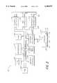
- FIG. 2is a block diagram which shows the basic functional elements of the keyboard and host computer used in accordance with the present invention.
- FIG. 3is a block diagram which details the major functional elements of the keyboard controller.
- FIG. 4is a flowchart which shows the general procedure used to convert the signals associated with certain keys into signals identical to those normally output by a mouse pointer device.
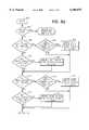
- FIG. 5is a more detailed flowchart which illustrates the method used to convert keystrokes to mouse data.
- FIG. 1ais a plan view of a modified keyboard 100 which may be used in accordance with the present invention.
- the keyboard 100is implemented within a notebook computer, although it should be understood that the present invention is not restricted to notebook computers.
- the keyboard 100has been modified to include an additional special function key 102, which is designated on the keyboard by an "Fn.”
- the keyboard 100also includes additional symbols on the front sloping face of certain keys. These additional symbols indicate the additional functions which may be performed upon activation of these keys while the special function (Fn) key 102 is depressed.
- Selected keys on the keyboard 100are interpreted in accordance with the present invention to emulate mouse operations when the Fn key 102 is active.
- the right and left cursor movement keys 110, 112, as well as the up and down cursor movement keys 114, 116are used to position a pointer on a computer screen in a manner similar to that accomplished by a conventional mouse pointer.
- the keys 110-116are designated with a mouse symbol 118 on their front sloping faces to aid the user.
- the cursor movement keys 110-116cause the cursor to move vertically or horizontally across the computer screen, as is well understood in the art.
- the cursor movementsare typically restricted to simple horizontal movement (i.e., horizontal movement with no simultaneous component of vertical movement) across lines of text in single character increments or simple vertical movement from one line of text to another.
- the cursortypically does not move diagonally, and it does not typically move in increments smaller than one line or character.
- the restricted movement of the cursoris not desirable in certain applications (e.g., pull-down menu, graphical and icon-based applications) where a mouse pointer is generally preferred.
- the operation of the cursor movement keys 110-116are interpreted when the Fn key 102 is active to emulate a PS/2 compatible mouse pointing device.
- the apparatus and method by which these modifications are accomplishedwill be described in detail with reference to FIGS. 2-5d below.
- the operation of the cursor movement keys 110-116is interpreted to enable positioning of the cursor at any point on the computer screen, and to enable diagonal, vertical and horizontal movement.
- a cursor of this kindis typically called a pointer, and may be represented on the computer screen, for example, by an arrow, a cross or the like.
- the operation of the cursor movement keys 110-116may be further interpreted to provide adjustable pointer speeds so that the speed of the pointer as it moves across the screen is gradually increased in increments while the cursor keys 110-116 remain active. These modifications in the operation of the cursor movement keys 110-116 serve to provide a system wherein the movement of the pointer, as controlled by the cursor movement keys 110-116, emulates the movements obtained via a conventional mouse pointer.
- the method and apparatus of the present inventionprovide mouse data (i.e., data which is typically transmitted from a conventional mouse pointer device) to a host computer operating system.
- the present inventionalso provides for additional mouse functions to be implemented via the keyboard 100.
- the operation of the "z" and "x" keys 120, 122may be interpreted to emulate the left and right buttons on a two-button mouse.
- the keyboardmay similarly be modified to emulate the operations of a one- or three-button mouse as well.
- the mouse-lockcauses the designated mouse keys (i.e., keys 110-116 and 120-122 in the embodiment shown in FIG. 1) to lock into mouse emulation operations so that it is not necessary to hold down the function (Fn) key 102 while using these designated mouse keys to perform mouse functions.
- the function key 125labeled F10, may be used as a mouse-lock key when depressed simultaneously with the special function (Fn) key 102. Simultaneously depressing the special function (Fn) key 102 and the F10 function key 125 a second time turns off the mouse-lock function.
- FIG. 1causes the designated mouse keys (i.e., keys 110-116 and 120-122 in the embodiment shown in FIG. 1) to lock into mouse emulation operations so that it is not necessary to hold down the function (Fn) key 102 while using these designated mouse keys to perform mouse functions.
- the function key 125labeled F10
- FIG. 1bis an enlarged view of the F10 key 125 which illustrates the screening of an icon representing the mouse-lock function on a front face of the F10 key 125, which indicates to the user that the F10 key 125 can be used in combination with the Fn key 102 to activate a mouse lock function.
- selected keys on the keyboard 100in combination with control circuitry described below, when used in accordance with the present invention, emulate mouse pointer operations.
- the userIn order to initiate modification of the operation of the cursor movement keys 110-116, the z and x keys 120, 122 and the F10 key 125 to perform mouse-like operations, the user simply depresses the special function (Fn) key 102 and also depresses one or more of the keys 110-116, 120, 122, 125, designated as mouse keys, while holding down the Fn key 102. For example, if the user is holding down the function (Fn) key 102, while simultaneously depressing the left cursor key 112 and the up cursor key 114, the pointer on the screen will move at an angle of approximately 45° across the screen. In order to increase the speed of the pointer in one embodiment, the user merely holds the appropriate keys down for a predetermined period.
- Fnspecial function
- the system of the present inventionautomatically increases the pointer speed by preset increments over a pre-selected time interval (e.g., in the present embodiment, an increase in pointer speed occurs on a preselected 400 millisecond interval up to a maximum predefined speed).
- FIG. 2is a block diagram which depicts the main functional elements of a microprocessor based computer system 200.
- the system 200includes the modified keyboard 100, with the special function (Fn) key 102.
- the keyboard 100 in FIG. 2is also depicted with the keys 110, 112, 114, 116, 120, 122, 125 selected for use in emulating a mouse pointer device.
- the keyboard 100is connected to a keyboard controller 202 via signal lines 204.
- the keyboard controller 202is typically internal to the keyboard 100, but is depicted as a separate block for illustration.
- the keyboard controller 202is connected to the host system via a processor bus 214.
- the host systemmay include a number of processing devices such as a CPU (an Intel® 80286, 80386, 80486, or the like, designated as 80 ⁇ 86 in FIG. 2) 210, a RAM 220, a co-processor 222, a refresh controller 224, clocks and timers 226, an interrupt controller 230, a DMA controller 232, interface circuitry 234, and a ROM 238. All of these processing devices are in communication with the keyboard controller via the processor bus 214.
- the interrupt controller 230, the DMA controller 232, and the interface circuitry 234are additionally connected to an Industry Standard Architecture (ISA) bus 240.
- ISAIndustry Standard Architecture
- the keyboard controller 202is connected to the interrupt controller 230 by means of an IRQ 12 signal line 250.
- the keyboard controller 202is activated whenever a key on the keyboard 100 is depressed. Once a key is depressed, the keyboard controller 202 scans the keyboard 100 to determine which one or more keys were activated. The keyboard controller 202 evaluates each key in order to determine if data (e.g., a conventional scan code) identifying the key should be transmitted to the operating system computer, or if the keystrokes should be interpreted further. For example, if the key is not the Fn key 102, the keyboard controller 202 transmits data (e.g., a conventional scan code) to the CPU 210 which indicates to the host which key was pressed. However, if the active key is the special function (Fn) key 102, then the keyboard controller 202 does not transmit scan code data to the CPU 210.
- datae.g., a conventional scan code
- the keyboard controller 202interprets the subsequent keystrokes and outputs modified data to the CPU 210.
- the keyboard controller 202does not inform the host computer operating system (i.e., send a scan code to the CPU 210) that this key has been pressed.
- the keyboard controller 202waits for the keystrokes which follow while the special function (Fn) key 102 remains active, and executes a predefined function assigned to the keys before sending data to the operating system.
- the keyboard controller 202interprets any keys activated during activation of the special function (Fn) key 102. If the keystrokes following activation of the Fn key 102 are from the designated "mouse keys" (i.e., keys 110-116, 120, 122, or 125), then the keyboard controller 202 does not transmit the data (e.g., conventional scan code) which would normally be sent to the operating system to identify these keys, but transmits data which emulates the data which the operating system would normally receive from a mouse pointing device. The emulated mouse data forwarded by the keyboard controller is indistinguishable by the operating system from data which is normally generated from a conventional mouse pointer.
- the datae.g., conventional scan code
- the operating systemreceives the data as though it were from a conventional mouse pointer connected to the mouseport.
- a conventional mouse pointerconnected to the mouseport.
- FIGS. 4-5dA more detailed description of the procedure employed by the keyboard controller 202 to provide emulated mouse data to the host is discussed with reference to the flowcharts of FIGS. 4-5d below.
- FIG. 3is a block diagram which details the major functional elements of one embodiment of the keyboard controller 202.
- the keyboard controller 202has a core 8-bit CPU 304, a host/core interface 306, a memory controller 307, a keyboard scanner 308, a local interrupt controller 310, and input/output lines 314. These elements are interconnected by means of an internal bus 320.
- the Intel 80C51SL AG keyboard controller or AST Research, Inc.'s MIKI keyboard controllerare examples of appropriate keyboard controllers used in computer systems which utilize the keyboard controller as an interface between a mouse and the operating system.
- the keyboard controller 202is connected via an input/output bus 300 to the host computer (designated generally here as 302).
- the host computergenerally comprises the CPU (80 ⁇ 86) 210, ROM 238, the refresh controller 224, the clocks and timers 226, and a display 305, the DMA controller 232, the interrupt controller 230 and the interface circuitry 234, as is well understood in the art.
- the input/output bus 300includes the input and output connections to ports 60 hex and 64 hex (i.e., the conventional input and output ports) of the keyboard controller 202, as well as the interrupt connection line 250, which is connected to the interrupt request terminal 12 (IRQ 12) of the interrupt controller 230.
- the keyboard controller 202is also connected to the keyboard 100 via signal lines 204, and to one or more serial input/output peripheral devices 303 via signal lines 301.
- the memory controller 307is further connected to a memory 322 via signal lines 324. Although the memory 322 is shown in FIG. 3 as being external to the keyboard controller 202, it should be understood that the memory 322 may also be internal to the keyboard controller 202.
- the keyboard controller 202executes instructions stored in the memory 322.
- the general method used by the keyboard controller 202 to emulate mouse operationsis described with reference to the flowchart of FIG. 4. Instructions controlling execution by the keyboard controller 202 to carry out the tasks of FIGS. 4-5d are stored in the memory 322 for the keyboard controller.
- the flowchartbegins in a start block 400. In one embodiment, the operations which follow the start block 400 are only executed after the keyboard controller detects that at least one key on the keyboard has been depressed.
- Control of operations of the present inventionbegins at a decision block 405, wherein a determination is made if the special function (Fn) key 102 is currently depressed. If the function (Fn) key 102 is not depressed, the keyboard controller 202 transmits the keystroke data corresponding to the key (or keys) which is (are) active to the operating system of the host 302, as represented in a process block 410. If the function (Fn) key 102 is depressed, the keyboard controller 202 interprets the subsequent keystroke signals generated by the keyboard 100 while the function (Fn) key 102 is depressed, as represented in a process block 415. The keyboard controller then determines if these subsequent keystroke signals are signals from the designated mouse control keys, as represented in a decision block 420.
- the keyboard controller 202makes this determination by examining the active keys via the keyboard scanner 308 and determining if any active keys include the designated mouse keys 110-116, 120, 122, 125 (FIG. 3). If the signals are not from the designated mouse control keys, then control passes to a process block 421, wherein other keys predefined to perform special functions are processed by the keyboard controller 202.
- the keyboard controller 202generates an interrupt request signal (IRQ 12) and transmits the IRQ 12 to the host 302 via the signal line 250 (FIG. 2). This indicates to the host computer that the data from the keyboard controller 302 which follows will be mouse data.
- the hostwill then execute a routine (a mouse driver) activated by the IRQ 12 interrupt signal to process the incoming mouse data.
- Controlpasses from the process block 425 to a subroutine block 430, wherein the signals from the designated mouse control keys 110-116, 120, 122, 125 are processed and converted into mouse data.
- Thisis advantageously accomplished by means of the core CPU 304.
- the core CPU 304executes instructions in the memory 322 to process the data received from the keys and generate mouse data.
- the method employed within the subroutine block 430is described in greater detail with reference to the flowchart of FIGS. 5a-5d below.
- an appropriate reporti.e., sample
- the mouse datais transmitted to the host 302, as represented in an action block 435. If the appropriate report period has not elapsed, however, control returns to the start of the method.
- the action block 432represents a decision whether any new data is available in the packet. For instance, has the state of a mouse key changed or has the mouse moved since the last data was sent to the host. If no change has occurred in the packet awaiting transmission to the host 302, then the packet need not be transmitted.
- the creation of mouse datais effectively transparent to the operating system of the host 302.
- the operating system of the host 302receives no indication that the designated mouse keys on the keyboard were depressed, but simply receives data indicating mouse movement and control as if the data originated from a mouse connected to the mouseport.
- the host computer 302is advantageously equipped with mouse driver software. Because in the present embodiment the keyboard mouse operation emulates a conventional PS/2-compatible mouse connected to a conventional mouseport, the mouse driver software of the host which processes the mouse data provided by the keyboard controller 202 is a conventional PS/2 mouse driver, and is well known in the art. For example, appropriate mouse drivers which may be used in accordance with the present invention can be obtained from Microsoft.
- the mouse driveris typically a terminate and stay resident (TSR) program which is installed for execution by the host computer 302 when the host 302 receives the IRQ 12. After installation, TSR programs remain within the memory of the host 302. Thus, these programs are transparent during normal operation of the host computer 302.
- a TSR programmay be activated by means of an interrupt signal generated by an appropriate source (e.g., the keyboard controller 202).
- the mouse driver programis activated when an interrupt signal is generated by the keyboard controller 202 and applied to the IRQ 12 input terminal of the interrupt controller 230.
- the interrupt controller 230instructs the CPU 210 of host computer 302 to address the memory location where the mouse driver program is located in memory.
- the mouse driver programthen processes the mouse data from the keyboard controller 202 as if the data were from a conventional mouse pointing device.
- FIGS. 5a-5ddetails the process represented by the subroutine block 430 (i.e., the process of generating mouse data for the host 302).
- the routinebegins at a start block 500.
- the keyboard controller 202determines whether the mouse is disabled as represented in a decision block 502.
- the operating systemperforms two tests to determine if a mouse is connected to the system.
- the first testdetermines whether or not a mouse is attached to the mouseport. If a mouse is connected to the mouseport, the mouseport takes precedence, and a serial mouse is normally ignored. If no mouse is connected to the mouseport, the operating system performs a second test to determine whether a serial port mouse is being used. Due to sequence of operation of the host 302, the use of a serial port mouse in combination with the keyboard emulated mouse of the present invention would normally result in the serial port mouse being ignored. This is because the present invention emulates a mouse connected to the mouseport, and the system would always ignore a serial port mouse because the keyboard mouse would always indicate the presence of a mouseport mouse.
- the present inventionprovides an option list for the user during set-up operations of the computer.
- the list of selections during set-upis as follows:
- the userselects, during set-up of the computer system 302, which type of mouse is desired. If the user selects a serial port mouse at set-up, then this sets a keyboard mouse disable bit. The test performed by the keyboard controller 202 in decision block 502 determines whether this disable bit has been set. If the disable bit has been set, then the keyboard mouse emulator is disabled and control returns to the beginning of the keyboard routine (e.g., the start block 400 of FIG. 4). If the keyboard mouse emulator is not disabled, then the keyboard controller 202 proceeds to interpret designated mouse keys active during activation of the Fn key 102. The data provided by the keyboard controller 202 are stored in conventional mouse data packets.
- each data packetcomprises three bytes of binary data and has several fields.
- some fields of the data packetcontain data indicating the state (inactive or active) of the left button key or right button key
- fieldscontain a number of X and/or Y counts (i.e., increments of directional movement in the X and/or Y directions, as utilized by the mouse driver to move the pointer on the screen) and fields contain data indicating whether an overflow has occurred in the X counts or Y counts.
- a new data packetis sent to the host 302 periodically at time intervals (the report interval) determined by a value contained in a programmable register (the Report Interval register) within the keyboard controller 202.
- the value within this registereffectively regulates the sample rate of the system 200 (i.e., the rate at which the host receives mouse data packets).
- the sample rateranges from 10 data-packets per second to 200 data-packets per second, and the register values assigned in the present embodiment correspond to sample rates as shown in the table below:
- the Report Interval register valueindicates the number of times the keyboard controller 202 passes through the control program illustrated in FIG. 4 before a packet is transmitted to the host.
- the rate at which data packets are sent to the host 302may be changed by simply changing the Report Interval register value.
- the sampling rateis regulated periodically in response to the number of data overflows for packets transmitted to the host within a given time interval.
- decision block 502If the keyboard mouse is not disabled (decision block 502), interpretation of the mouse keys begins in the decision block 504 of FIG. 5a.
- decision block 504a test is performed to determine if the key assigned to act as the left button of a two-button mouse (i.e., the left button key 120 (FIG. 1)) is pressed. If the left button key 120 is pressed, then control passes to a decision block 506.
- one bit in each data packetrepresents the state of the left button.
- the state of this bitstays the same for consecutive packets in accordance with the last change of this bit. Therefore, at the decision block 506, the keyboard controller 202 performs a test to determine if the left button key 120 has changed state since the last test. If the left button key 120 has not changed state since the last test, then this indicates that the user was holding the left button key 120 down during the last pass through this procedure, and the bit in the data packet reflecting the state of the left button key 120 need not be changed in the next packet sent to the host 302. Thus, control passes to a decision block 510.
- the left button key 120has changed state since the last test, this indicates that the user has just activated the left button key 120 and the bit in the next data packet which reflects the state of the left button should be set.
- the mouse driverinterprets the bit to determine that the left button of the mouse was just depressed.
- controlpasses to a process block 508, and data indicating that the left mouse button switch state has changed to closed is placed into a data packet (i.e., the left button state bit is set in the present embodiment).
- the keyboard controller 202sets a "packet changed" flag (not part of the mouse data packet) which indicates to the keyboard controller 202 that the data packet has changed. Thereafter, control passes to the decision block 510.
- the keyboard controller 202again determines if the state of the key has changed since the last test. As explained above, this is because the next data packet to the host will represent the previous state of the left button. Therefore, if a change has occurred, the appropriate bit should be altered. Accordingly, the keyboard controller 202 determines if the state has changed since the last test, as represented in a decision block 507. If the state has not changed since the last test (i.e., the left button was inactive during the last test), then the keyboard controller 202 proceeds to determine if the right button key is pressed, as represented in an action block 510.
- the keyboard controller 202changes the left switch state bit in the data packet to reflect the new inactive state, as represented in action block 509 (i.e., the keyboard controller clears the bit in the data packet, which represents the state of the left button of a mouse), and sets the packet changed flag.
- the keyboard controller 202determines if the right button key 122 (i.e., the key assigned to represent the right button on a mouse) is currently active, as represented in the decision block 510. If the right button key 122 is active, then control passes to a decision block 512, and a determination is made whether the state of the right button key 122 has changed since the last test. If the right button key 122 has not changed state since the last test, then this indicates that the user was holding the right button key 122 down during the last execution of the subroutine, and a bit in the packet representing the state of the right mouse button already represents the current state. Thus, control passes to a decision block 516 (FIG. 5b).
- the right button key 122i.e., the key assigned to represent the right button on a mouse
- the keyboard controller 202 of the present inventioninterprets the designated mouse keys to emulate the operation of a mouse connected to the mouseport. Accordingly, when the keyboard controller 202 determines that the right button key 122 has been activated, the data which is stored in the data packet currently being constructed for transmission to the host 302 is the same data which would be generated if a mouse were actually connected to the mouseport.
- the keyboard controller 202determines if the state of the right button key 122 has changed since the last test, as represented in an action block 513. If the state has not changed since the last test, then the bit which represents the state of the right button of a mouse in the next packet to be sent to the host 302 already represents the open or inactive state of the right mouse button, and control passes directly to the decision block 516 (FIG. 5b). If the state has changed since the last test (the decision block 513), this indicates that the user released the right button key 122 since the last execution of the subroutine.
- the keyboard controllerchanges the state of the bit in the data packet which represents the right button of the mouse to open or inactive (i.e., it clears the corresponding bit), as represented in an action block 515, and sets the packet changed flag. Thereafter, control passes to the decision block 516 (FIG. 5b).
- Blocks 516-564illustrate the operation of the mouse pointer movement keys (i.e., the cursor keys 110-116).
- the procedure for converting the data obtained from these keys into mouse datais generally the same for each key, so that the same method is repeated for the up, down, right and left cursor keys.
- the keyboard controller 202checks a Mouse Timer value, as represented in a decision block 516.
- the Mouse Timer valueindicates the frequency at which the X-counter and Y-counter values are incremented or decremented with the speed value.
- the Mouse Timer valueacts as a test value or delay time before the keyboard controller 202 proceeds through the mouse key conversion routine and again adds or subtracts the speed value to the X-counter or Y-counter, as may be the case.
- the Mouse Timer valuemay be set to 12.5, 25, 50 or 100 increments/decrements of the Y-counter and X-counter per second. In other words, the Mouse Timer value determines a Mouse Timer period.
- the Mouse Timer periodis amount of the time assigned for each pass through the routine which converts the mouse keys to mouse data.
- the X-counter and Y-counterare incremented/decremented when appropriate during each Mouse Timer period.
- the increments/decrements per second (Mouse Timer) valueis advantageously set during set-up operations.
- the procedure employed in accordance with the present inventioncould allow a user to update the Mouse Timer value at any time during the operation of the mouse emulation system 200.
- the Mouse Timer valueperforms a function similar to resolution in a conventional mouse.
- the keyboard controller 202first determines if the up cursor key 114 is currently depressed (active), as represented in the action block 518. If the up cursor key 114 is not active, then the keyboard controller 202 begins processing the down cursor, beginning at a decision block 530 (FIG. 5c), through a continuation point A. However, if the up cursor key 114 is active (as determined at the decision block 518), then control passes from the decision block 518 to a process block 520, and the keyboard controller 202 retrieves a current value of a Y-counter. The Y-counter value is related to the vertical distance that the pointer is to be moved on the computer screen.
- the Y-counter value(as well as an X-counter value, explained below) maintains a running count total of the movement of the mouse since the last packet was sent to the host. These counters are cleared each time a packet is sent to the host, and begin incrementing and/or decrementing with mouse movement (active mouse keys) until the next packet is sent to the host.
- the "speed" valuemay assume a value of one, two or three in the present embodiment, and is used to adjust the rate at which the pointer moves across the screen. Since the value of the Y-counter is directly proportional to the distance the pointer moves up or down the computer screen, and the Y-counter is incremented or decremented by the speed value every time through the subroutine loop while the up or down cursor keys are active, the rate at which the pointer moves across the screen is proportional to the speed value.
- the keyboard controllerincrements the Y-counter value by a value of one until the speed value is changed. If the speed value is set to three, then the Y-counter value will be incremented by three each time through the loop while the up cursor key 114 remains active. Thus, the Y-counter value increases three times as fast when the speed value is set to three as when the speed value is set to one.
- a Y-overflow flag(e.g., a single bit) is also set in the current mouse data packet, indicating a Y-counter overflow has occurred.
- the keyboard controller 202also sets the packet-changed flag.
- the Y-counter valueit is possible for the Y-counter value to be incremented and/or decremented several times before its value is transmitted to the host 302 in a data packet. Therefore, it is advantageous to transmit data packets at a rate concordant with the incrementing rate of the Y-counter. For example, if a data packet is sent so infrequently that the Y-counter overflows and is reset to its maximum value several times before the data packet is sent, then the speed of the pointer on the computer screen will not accurately reflect the rate at which the Y-counter is being incremented. Hence, there will be little or no difference if the speed value is set to one, two, or three. Thus, it is advantageous if the rate at which the data packets are sent is correlated relative to the speed value.
- the likelihood that the Y-counter value will exceed its maximum valuetherefore depends upon the report interval (i.e., the sample rate at which packets are sent to the host computer 302) and the speed value. If the Y-counter value exceeds its maximum value on numerous occasions in a given time interval, this indicates that the sample rate is probably too slow.
- the keyboard controller 202monitors the number of times the Y-counter value exceeds its maximum value (i.e., the number of overflows) during a given interval, and increases the sample rate by a predetermined increment until the Y-counter value does not exceed its maximum (e.g., overflow) during the predetermined interval.
- the keyboard controller 202determines if the down cursor key 116 is currently active. If the down cursor key 116 is not active, then the keyboard controller 202 begins processing the right cursor key, beginning with a decision block 542. However, if the down cursor key 116 is active, then control passes from the decision block 530 to a process block 532, and the keyboard controller 202 retrieves the current value of the Y-counter.
- the keyboard controller 202determines if an overflow in the Y-counter has occurred in the negative direction. If a negative overflow in the Y-counter has not occurred, control passes to a process block 540.
- Controlpasses to a process block 538, the Y-counter is set to its minimum value, and the Y-overflow flag is set in the current data packet, indicating the overflow in the Y-counter. Control then passes to the process block 540, wherein the new Y-counter value replaces the previous Y-counter value in the current data packet.
- the packet-changed flagis also set, indicating to the keyboard controller 202 that the mouse data packet has changed.
- the keyboard controller 202determines if the right cursor key 110 is active. If the right cursor key 110 is not active, then the keyboard controller 202 begins processing the left cursor key 112, beginning at a decision block 554. However, if the right cursor key 110 is active (decision block 542), then control passes from the decision block 542 to a process block 544, and the keyboard controller 202 retrieves the current value of an X-counter.
- the X-counter valueis the horizontal equivalent of the Y-counter value, and serves a similar function (i.e., to indicate the distance that the pointer is moved on the screen in the horizontal direction).
- the keyboard controller 202adds the current speed value to the value within the X-counter, to replace the current X-counter value, as represented in a process block 546.
- controlpasses to a decision block 548.
- the keyboard controller 202determines if the X-counter has overflowed in the positive direction. If a positive overflow has not occurred in the X-counter, control passes to a process block 552. However, if the X-counter has overflowed in the positive direction, this indicates that the X-counter value has exceeded its maximum value (e.g., exceeded 127 in the present embodiment). Control therefore passes to a process block 550, and the keyboard controller 202 sets the X-counter to its maximum value and sets an X-overflow flag (e.g., a single bit) in the current data packet. The keyboard controller 202 then replaces the previous X-counter value with the new X-counter value in the current mouse data packet and sets the packet-changed flag.
- the keyboard controller 202determines if the left cursor key 112 is currently active, as represented in the decision block 554. If the left cursor key 112 is active, then control passes to a decision block 566 (FIG. 5d) through a continuation point B. However, if the left cursor key 112 is active, then control passes from the decision block 554 to a process block 556, and the keyboard controller 202 retrieves the current value of the X-counter.
- the keyboard controller 202subtracts the current speed value from (i.e., adds the corresponding twos-complement to) the value within the X-counter, and replaces the original X-counter value, as represented in a process block 558.
- controlpasses to a decision block 560.
- the keyboard controller 202determines if the X-counter has overflowed in the negative direction. If the X-counter has not overflowed in the negative direction, control passes to a process block 564.
- Controlpasses to a process block 562, and the keyboard controller 202 sets the X-counter to its minimum value and also sets an X-overflow flag in the current mouse data packet.
- the keyboard controller 202then replaces the previous X-counter value in the current mouse data packet with the new X-counter value. as represented in the process block 564. Additionally, the keyboard controller 202 sets the changed-packet flag.
- the changed-packet flagis set anytime data changes in the mouse data packet. This is for use by the keyboard controller 202 to determine if there is any new data in a packet which needs to be sent to the host 302 at the proper report interval.
- the keyboard controller 202determines if the speed value should be reset to a value of one.
- the speed valueis reset to a value of one each time the user releases all of the cursor keys 110-116. This assures that the next time the user presses a cursor key, the speed of the pointer will start at a moderate speed and gradually accelerate to the maximum speed if the cursor key is held down for the preselected interval.
- the keyboard controller 202sets the speed value to one, as represented in a process block 568. From the process block 568, control returns to the subroutine of FIG. 4 at the decision block 431.
- the keyboard controllerdetermines that the speed value should not be reset, then control passes from the decision block 566 to an action block 570, and the keyboard controller 202 resets the Mouse Timer value.
- the Mouse Timer valueis reset to correspond to the resolution of the mouse as follows:
- the Mouse Timeris set to a value such that the keyboard controller will check the up, down, right and left cursor keys 12.5 times every second (1 time every 8 milliseconds).
- the keyboard controller 202determines if the report interval (e.g., the sample interval) has expired. In other words, the keyboard controller 202 determines if it is time to forward a data packet to the host 302. If the report interval has not elapsed, as determined at the decision block 431, control returns to the beginning of the routine, and the keyboard controller 202 again processes the mouse keys, as explained above. If the sample interval has elapsed, the keyboard controller 202 determines if the current mouse packet has changed, as represented in a decision block 432, by checking the changed-packet flag. If the data packet has not changed since the transmission of the last data packet, then control returns to the beginning of the subroutine and the packet is not sent.
- the report intervale.g., the sample interval
- the keyboard controller 202transmits the mouse data packet to the host via the output port of the keyboard controller 202.
- the transmission of the mouse data packetproceeds following conventional protocols as if the data packet were from a conventional mouse connected to the mouse port, as is well understood in the art.
- the transmission of data to the hostis represented in an action block 435.
- the keyboard controller 202will detect this in its key detection routine, and data representing the activity of the active keys will be stored in the packet. Accordingly, if a horizontal cursor key and a vertical cursor key are both simultaneously depressed and remain active for the same period of time, the pointer will effectively move in a 45° direction across the screen. If a vertical key and a horizontal key are simultaneously pressed for a portion of a sample interval, and for the remainder of the sample interval only a vertical or horizontal key remains active, the number of X counts and Y counts transmitted to the host will be uneven, and the angle of movement across the computer screen will be other than 45°.
- data packets as described in FIGS. 5a-5d aboveare substantially the same in format to data packets which are generated by mouse pointer devices connected to the mouseport.
- mouse commands used in accordance with the present inventionfollow standard mouse protocol which is well known in the art.
- the present inventionmay be embodied in other specific forms without departing from its spirit or essential characteristics.
- additional keysmay be designated to function with the Fn key 102 in order to increase the range of directions that the pointer may be moved on the screen.
- the inventionmay be modified to emulate a one-button or three-button mouse.
Landscapes
- Engineering & Computer Science (AREA)
- General Engineering & Computer Science (AREA)
- Theoretical Computer Science (AREA)
- Human Computer Interaction (AREA)
- Physics & Mathematics (AREA)
- General Physics & Mathematics (AREA)
- Input From Keyboards Or The Like (AREA)
Abstract
Description
______________________________________ Report Timer Register Value Sampling Rate ______________________________________ 20 10 data-packets/sec 10 20 data-packets/sec 5 40 data-packets/sec 4 60 data-packets/sec 3 80 data-packets/sec 2 100 data-packets/sec 1 200 data-packets/sec ______________________________________
______________________________________ Mouse Timer (counts/second) Mouse Resolution (counts/mm) ______________________________________ 12.5 counts/second 1 counts/mm 25 counts/second 2 counts/mm 50 counts/second 4 counts/mm 100 counts/second 8 counts/mm ______________________________________
Claims (11)
Priority Applications (1)
| Application Number | Priority Date | Filing Date | Title |
|---|---|---|---|
| US08/174,215US6100875A (en) | 1992-09-03 | 1993-12-28 | Keyboard pointing device |
Applications Claiming Priority (2)
| Application Number | Priority Date | Filing Date | Title |
|---|---|---|---|
| US93982192A | 1992-09-03 | 1992-09-03 | |
| US08/174,215US6100875A (en) | 1992-09-03 | 1993-12-28 | Keyboard pointing device |
Related Parent Applications (1)
| Application Number | Title | Priority Date | Filing Date |
|---|---|---|---|
| US93982192AContinuation | 1992-09-03 | 1992-09-03 |
Publications (1)
| Publication Number | Publication Date |
|---|---|
| US6100875Atrue US6100875A (en) | 2000-08-08 |
Family
ID=25473795
Family Applications (1)
| Application Number | Title | Priority Date | Filing Date |
|---|---|---|---|
| US08/174,215Expired - LifetimeUS6100875A (en) | 1992-09-03 | 1993-12-28 | Keyboard pointing device |
Country Status (1)
| Country | Link |
|---|---|
| US (1) | US6100875A (en) |
Cited By (60)
| Publication number | Priority date | Publication date | Assignee | Title |
|---|---|---|---|---|
| US20010015718A1 (en)* | 1998-09-14 | 2001-08-23 | Hinckley Kenneth P. | Method for displying information responsive to sensing a physical presence proximate to a computer input device |
| US6321281B1 (en)* | 1997-10-14 | 2001-11-20 | Nec Corporation | Pointing device with a controller for monitoring a protocol selector signal derived from a computer to select one of a compatibility function and an additional function |
| US6330514B1 (en)* | 1999-02-09 | 2001-12-11 | Behavior Tech Computer Corp. | Keyboard testing system |
| US6333753B1 (en) | 1998-09-14 | 2001-12-25 | Microsoft Corporation | Technique for implementing an on-demand display widget through controlled fading initiated by user contact with a touch sensitive input device |
| US20020010816A1 (en)* | 1997-12-18 | 2002-01-24 | Patrick H. Tomoson | Computer peripheral switching device |
| US20020023271A1 (en)* | 1999-12-15 | 2002-02-21 | Augenbraun Joseph E. | System and method for enhanced navigation |
| US6377243B1 (en)* | 1997-07-30 | 2002-04-23 | International Business Machines Corporation | Data input device and the method thereof |
| US6396477B1 (en)* | 1998-09-14 | 2002-05-28 | Microsoft Corp. | Method of interacting with a computer using a proximity sensor in a computer input device |
| US20020080273A1 (en)* | 1999-01-06 | 2002-06-27 | Harrison Robert G. | Appliance with TV and INTERNET modes of operation |
| US20020095480A1 (en)* | 1996-11-27 | 2002-07-18 | Diebold, Incorporated | Automated banking machine apparatus and system |
| US6456275B1 (en) | 1998-09-14 | 2002-09-24 | Microsoft Corporation | Proximity sensor in a computer input device |
| US6469694B1 (en)* | 1999-04-13 | 2002-10-22 | Peter J. Mikan | Mouse emulation keyboard system |
| US20020158846A1 (en)* | 2001-04-30 | 2002-10-31 | Clapper Edward O. | Controlling cursor of a pointing device |
| US20020171564A1 (en)* | 2001-05-21 | 2002-11-21 | Mehrban Jam | Keyboard with integrated pointer control function |
| US20030011576A1 (en)* | 2000-03-30 | 2003-01-16 | Sandbach David Lee | Data processing apparatus with replacement keyboard |
| US20030018580A1 (en)* | 1996-11-27 | 2003-01-23 | Diebold, Incorporated | Automated banking machine apparatus and system |
| US6545666B1 (en)* | 2000-05-30 | 2003-04-08 | Agilent Technologies, Inc. | Devices, systems and methods for positioning cursor on display device |
| US20030078866A1 (en)* | 1996-11-27 | 2003-04-24 | Diebold, Incorporated | Automated banking machine system using plural communication formats |
| US20040160412A1 (en)* | 2003-02-13 | 2004-08-19 | Sony Corporation | Information processing apparatus |
| US20040160413A1 (en)* | 2003-02-13 | 2004-08-19 | Sony Corporation | Information processing apparatus |
| US6788284B1 (en)* | 2000-05-30 | 2004-09-07 | Agilent Technologies, Inc. | Devices, systems and methods for position-locking cursor on display device |
| US6795055B1 (en)* | 2000-05-30 | 2004-09-21 | Agilent Technologies, Inc. | Devices, systems and methods for facilitating positioning of cursor on display device |
| US6963333B1 (en)* | 1996-11-27 | 2005-11-08 | Diebold, Incorporated | Automated banking machine apparatus and system |
| US20050273427A1 (en)* | 1996-11-27 | 2005-12-08 | Diebold, Incorporated | Automated banking machine apparatus and system |
| US20050289055A1 (en)* | 1996-11-27 | 2005-12-29 | Diebold, Incorporated | Automated banking machine apparatus and system |
| US20060033705A1 (en)* | 2004-08-11 | 2006-02-16 | Hyuk Jeong | Mouse pointer controlling apparatus and method |
| US20060070009A1 (en)* | 2004-09-27 | 2006-03-30 | Chaucer Chiu | Key-controlled multi-level window activating method and interface |
| US20060082548A1 (en)* | 2004-10-20 | 2006-04-20 | Kodama Robert R | Computer keyboard with pointer control |
| US20060136336A1 (en)* | 1996-11-27 | 2006-06-22 | Diebold, Incorporated | Automated banking machine and system |
| US20060164392A1 (en)* | 2005-01-21 | 2006-07-27 | Chaokuo Mao | Integrated mouse and the keyboard device |
| US7245369B2 (en) | 2003-11-13 | 2007-07-17 | B & W Tek, Inc. | Spectroscopic apparatus using spectrum narrowed and stabilized laser with Bragg grating |
| US7275836B2 (en) | 2005-08-13 | 2007-10-02 | Palm, Inc. | Lighting and usability features for key structures and keypads on computing devices |
| US7294802B2 (en) | 2005-08-13 | 2007-11-13 | Palm, Inc. | Lighting and usability features for key structures and keypads on computing devices |
| US7358956B2 (en) | 1998-09-14 | 2008-04-15 | Microsoft Corporation | Method for providing feedback responsive to sensing a physical presence proximate to a control of an electronic device |
| US7499032B1 (en)* | 2002-01-18 | 2009-03-03 | Mikan Peter J | Keypad computer mouse emulation system |
| US7511700B2 (en) | 2005-03-14 | 2009-03-31 | Palm, Inc. | Device and technique for assigning different inputs to keys on a keypad |
| US7525053B2 (en) | 2006-09-08 | 2009-04-28 | Palm, Inc. | Enhanced key structure with combined keycap for a mobile computing device |
| US7525534B2 (en) | 2005-03-14 | 2009-04-28 | Palm, Inc. | Small form-factor keypad for mobile computing devices |
| CN100498659C (en)* | 2006-12-29 | 2009-06-10 | 中国电信股份有限公司 | Method and apparatus for providing mouse function for remote controller |
| US7623118B2 (en) | 2005-03-14 | 2009-11-24 | Palm, Inc. | Actuation mechanism for use with keyboards on mobile computing devices |
| GB2466077A (en)* | 2008-12-15 | 2010-06-16 | Symbian Software Ltd | Emulator for multiple computing device inputs |
| US20100182235A1 (en)* | 2009-01-19 | 2010-07-22 | Sony Corporation | Input device and input method, information processing device and information processing method, information processing system and program |
| US20110210918A1 (en)* | 2004-10-20 | 2011-09-01 | Kodama Robert R | Computer keyboard with pointer control |
| US20120075187A1 (en)* | 2010-09-24 | 2012-03-29 | Yuan-Chan Lee | Method for simulating a mouse device with a keyboard and input system using the same |
| US20120136607A1 (en)* | 2010-11-26 | 2012-05-31 | Primax Electronics Ltd. | Method and system for testing circuit board of keys |
| US8214539B1 (en) | 2009-02-23 | 2012-07-03 | Kulanko Robert J | Command mapping systems relating input devices to application program interfaces |
| US8310446B1 (en)* | 2006-08-25 | 2012-11-13 | Rockwell Collins, Inc. | System for integrated coarse and fine graphical object positioning |
| US20120289336A1 (en)* | 2011-05-09 | 2012-11-15 | Sony Computer Entertainment Inc. | Keyboard |
| US8350728B2 (en) | 2010-04-23 | 2013-01-08 | Hewlett-Packard Development Company, L.P. | Keyboard with integrated and numeric keypad |
| EP2389761A4 (en)* | 2009-04-02 | 2013-02-13 | Sony Corp | Tv widget animation |
| EP2392132A4 (en)* | 2009-04-02 | 2013-02-20 | Sony Corp | Tv widget multiview content organization |
| CN103197770A (en)* | 2013-04-01 | 2013-07-10 | 深圳数字电视国家工程实验室股份有限公司 | Method and device for TV (television) remote control simulating operation of mouse |
| TWI459244B (en)* | 2010-11-26 | 2014-11-01 | Winspeed Co Ltd | A fast speed switching method of multi devices functions setting |
| US8989822B2 (en) | 2006-09-08 | 2015-03-24 | Qualcomm Incorporated | Keypad assembly for use on a contoured surface of a mobile computing device |
| US9142369B2 (en) | 2005-03-14 | 2015-09-22 | Qualcomm Incorporated | Stack assembly for implementing keypads on mobile computing devices |
| US9645655B2 (en) | 2013-03-29 | 2017-05-09 | International Business Machines Corporation | Integrated touchpad and keyboard |
| CN108255321A (en)* | 2017-12-27 | 2018-07-06 | 长春北方化工灌装设备股份有限公司 | A kind of explosion-proof mouse of button and cursor movement accelerate control method |
| US10019119B2 (en) | 2010-09-09 | 2018-07-10 | 3M Innovative Properties Company | Touch sensitive device with stylus support |
| WO2021027628A1 (en)* | 2019-08-09 | 2021-02-18 | 华为技术有限公司 | Remote control response method, electronic device and computer readable storage medium |
| CN115421598A (en)* | 2022-09-26 | 2022-12-02 | 珠海天亿计算机设备有限公司 | A kind of operation method of keyboard button simulating mouse |
Citations (14)
| Publication number | Priority date | Publication date | Assignee | Title |
|---|---|---|---|---|
| US4680577A (en)* | 1983-11-28 | 1987-07-14 | Tektronix, Inc. | Multipurpose cursor control keyswitch |
| US4698626A (en)* | 1984-06-02 | 1987-10-06 | Brother Kogyo Kabushiki Kaisha | Coordinate-data input device for CRT display having cursor travel control means |
| US4736191A (en)* | 1985-08-02 | 1988-04-05 | Karl E. Matzke | Touch activated control method and apparatus |
| US4739128A (en)* | 1986-11-10 | 1988-04-19 | American Telephone And Telegraph Company, At&T Bell Laboratories | Thumb-controlled, hand-held joystick |
| US4812833A (en)* | 1986-05-30 | 1989-03-14 | Hitachi, Ltd. | Touch panel input device |
| US4853630A (en)* | 1987-08-28 | 1989-08-01 | Houston John S | Magnetic position sensor having spaced toroidal magnets in a state of equilibrium |
| US4879556A (en)* | 1986-10-27 | 1989-11-07 | Huka Developments B.V. | Joystick control unit using multiple substrates |
| US4992631A (en)* | 1989-06-02 | 1991-02-12 | Atari Corporation | Multi-directional switch assembly |
| US5027304A (en)* | 1987-10-02 | 1991-06-25 | Telecommunication Laboratories, Directorate General of Telecommunications , Ministry of Communications | Character multifont compression and restoration device |
| US5041819A (en)* | 1988-10-19 | 1991-08-20 | Brother Kogyo Kabushiki Kaisha | Data processing device |
| US5065146A (en)* | 1987-06-18 | 1991-11-12 | International Business Machines Corporation | Manually-operated control device |
| US5119078A (en)* | 1986-10-21 | 1992-06-02 | Grant Alan H | Computer work station with mnemonic keyboard |
| US5124689A (en)* | 1989-09-26 | 1992-06-23 | Home Row, Inc. | Integrated keyboard and pointing device system |
| US5262761A (en)* | 1987-09-08 | 1993-11-16 | Intelligent Micro Systems, Inc. | Displaying hierarchical tree-like designs in windows |
- 1993
- 1993-12-28USUS08/174,215patent/US6100875A/ennot_activeExpired - Lifetime
Patent Citations (14)
| Publication number | Priority date | Publication date | Assignee | Title |
|---|---|---|---|---|
| US4680577A (en)* | 1983-11-28 | 1987-07-14 | Tektronix, Inc. | Multipurpose cursor control keyswitch |
| US4698626A (en)* | 1984-06-02 | 1987-10-06 | Brother Kogyo Kabushiki Kaisha | Coordinate-data input device for CRT display having cursor travel control means |
| US4736191A (en)* | 1985-08-02 | 1988-04-05 | Karl E. Matzke | Touch activated control method and apparatus |
| US4812833A (en)* | 1986-05-30 | 1989-03-14 | Hitachi, Ltd. | Touch panel input device |
| US5119078A (en)* | 1986-10-21 | 1992-06-02 | Grant Alan H | Computer work station with mnemonic keyboard |
| US4879556A (en)* | 1986-10-27 | 1989-11-07 | Huka Developments B.V. | Joystick control unit using multiple substrates |
| US4739128A (en)* | 1986-11-10 | 1988-04-19 | American Telephone And Telegraph Company, At&T Bell Laboratories | Thumb-controlled, hand-held joystick |
| US5065146A (en)* | 1987-06-18 | 1991-11-12 | International Business Machines Corporation | Manually-operated control device |
| US4853630A (en)* | 1987-08-28 | 1989-08-01 | Houston John S | Magnetic position sensor having spaced toroidal magnets in a state of equilibrium |
| US5262761A (en)* | 1987-09-08 | 1993-11-16 | Intelligent Micro Systems, Inc. | Displaying hierarchical tree-like designs in windows |
| US5027304A (en)* | 1987-10-02 | 1991-06-25 | Telecommunication Laboratories, Directorate General of Telecommunications , Ministry of Communications | Character multifont compression and restoration device |
| US5041819A (en)* | 1988-10-19 | 1991-08-20 | Brother Kogyo Kabushiki Kaisha | Data processing device |
| US4992631A (en)* | 1989-06-02 | 1991-02-12 | Atari Corporation | Multi-directional switch assembly |
| US5124689A (en)* | 1989-09-26 | 1992-06-23 | Home Row, Inc. | Integrated keyboard and pointing device system |
Non-Patent Citations (12)
| Title |
|---|
| "Hot PC Products", Electronic Design, vol. 38, No. 11, p. 22 (Jun. 14, 1990). |
| "Windows on the Road", Howard Eglowstein, BYTE, vol. 17, No. 3, pp. 208-213, 216, 218, 220 (Mar. 1992). |
| Dell System 325NC User s Guide, pp. 2 16, 3 1 through 3 4, 3 15, Dell Computer Corporation (Jan. 1992).* |
| Dell System 325NC User's Guide, pp. 2-16, 3-1 through 3-4, 3-15, Dell Computer Corporation (Jan. 1992). |
| Hot PC Products , Electronic Design , vol. 38, No. 11, p. 22 (Jun. 14, 1990).* |
| Howard, Bill, "Field Mice: Different, Yes. Better, Maybe" PC Magazine, vol. 10, No. 17, pp. 111-112, 123-126, 133 (Oct. 15, 1991). |
| Howard, Bill, Field Mice: Different, Yes. Better, Maybe PC Magazine , vol. 10, No. 17, pp. 111 112, 123 126, 133 (Oct. 15, 1991).* |
| IBM Technical Disclosure Bulletin, vol. 15, No. 1 (Jun. 1972) <<Keyboard Overlay>> R.G. Gross. |
| IBM Technical Disclosure Bulletin, vol. 15, No. 1 (Jun. 1972) Keyboard Overlay R.G. Gross.* |
| Reinhardt, Andrew, "Touch-and-Feel Interfaces", BYTE, pp. 223-226. |
| Reinhardt, Andrew, Touch and Feel Interfaces , BYTE , pp. 223 226.* |
| Windows on the Road , Howard Eglowstein, BYTE , vol. 17, No. 3, pp. 208 213, 216, 218, 220 (Mar. 1992).* |
Cited By (96)
| Publication number | Priority date | Publication date | Assignee | Title |
|---|---|---|---|---|
| US20050203847A1 (en)* | 1996-11-27 | 2005-09-15 | Diebold, Incorporated | Automated banking machine and method |
| US7162449B2 (en) | 1996-11-27 | 2007-01-09 | Diebold, Incorporated | Automated banking machine apparatus and system |
| US20060136336A1 (en)* | 1996-11-27 | 2006-06-22 | Diebold, Incorporated | Automated banking machine and system |
| US7689509B2 (en) | 1996-11-27 | 2010-03-30 | Diebold, Incorporated | Method of using an automated banking machine |
| US7699219B2 (en) | 1996-11-27 | 2010-04-20 | Diebold, Incorporated | Automated banking machine apparatus and system |
| US20050289055A1 (en)* | 1996-11-27 | 2005-12-29 | Diebold, Incorporated | Automated banking machine apparatus and system |
| US7737950B2 (en) | 1996-11-27 | 2010-06-15 | Diebold, Incorporated | Automated banking machine and system |
| US20050273427A1 (en)* | 1996-11-27 | 2005-12-08 | Diebold, Incorporated | Automated banking machine apparatus and system |
| US6973443B2 (en) | 1996-11-27 | 2005-12-06 | Diebold, Incorporated | Automated banking machine apparatus and system |
| US20020095480A1 (en)* | 1996-11-27 | 2002-07-18 | Diebold, Incorporated | Automated banking machine apparatus and system |
| US6965879B2 (en) | 1996-11-27 | 2005-11-15 | Diebold, Incorporated | Automated banking machine system using plural communication formats |
| US6963333B1 (en)* | 1996-11-27 | 2005-11-08 | Diebold, Incorporated | Automated banking machine apparatus and system |
| US7590598B2 (en) | 1996-11-27 | 2009-09-15 | Diebold, Incorporated | Automated banking machine with record accessibility pre-check |
| US7333954B2 (en) | 1996-11-27 | 2008-02-19 | Diebold, Incorporated | Automated banking machine and system |
| US7251631B2 (en) | 1996-11-27 | 2007-07-31 | Diebold, Incorporated | Automated banking machine system using internet address customer input |
| US20030018580A1 (en)* | 1996-11-27 | 2003-01-23 | Diebold, Incorporated | Automated banking machine apparatus and system |
| US20080288402A1 (en)* | 1996-11-27 | 2008-11-20 | Diebold, Incorporated | Automated banking machine and system |
| US20030078866A1 (en)* | 1996-11-27 | 2003-04-24 | Diebold, Incorporated | Automated banking machine system using plural communication formats |
| US20050216408A1 (en)* | 1996-11-27 | 2005-09-29 | Diebold, Incorporated | Automated banking machine apparatus and system |
| US20030154167A1 (en)* | 1996-11-27 | 2003-08-14 | Diebold, Incorporated | Method of using an automated banking machine |
| US20030217004A1 (en)* | 1996-11-27 | 2003-11-20 | Diebold, Incorporated | Automated banking machine system using Internet address customer input |
| US20050119973A1 (en)* | 1996-11-27 | 2005-06-02 | Diebold, Incorporated | Automated banking machine with record accessibility pre-check |
| US7405724B2 (en)* | 1996-11-27 | 2008-07-29 | Diebold, Incorporated | Automated banking machine and method |
| US20050097047A1 (en)* | 1996-11-27 | 2005-05-05 | Diebold, Incorporated | Automated banking machine and system |
| US6839688B2 (en) | 1996-11-27 | 2005-01-04 | Diebold, Incorporated | Method of using an automated banking machine |
| US6377243B1 (en)* | 1997-07-30 | 2002-04-23 | International Business Machines Corporation | Data input device and the method thereof |
| US20040059849A1 (en)* | 1997-10-14 | 2004-03-25 | Reiji Fujikawa | Pointing device with a controller used for monitoring a protocol selector signal derived from a computer to select one of a compatibility function and an additional function |
| US6321281B1 (en)* | 1997-10-14 | 2001-11-20 | Nec Corporation | Pointing device with a controller for monitoring a protocol selector signal derived from a computer to select one of a compatibility function and an additional function |
| US7003600B2 (en) | 1997-10-14 | 2006-02-21 | Nec Corporation | Pointing device with a controller used for monitoring a protocol selector signal derived from a computer to select one of a compatibility function and an additional function |
| US6691189B2 (en) | 1997-10-14 | 2004-02-10 | Nec Corporation | Pointing device with a controller for monitoring a protocol selector signal derived from a computer to select one of a compatibility function and an additional function |
| US20020010816A1 (en)* | 1997-12-18 | 2002-01-24 | Patrick H. Tomoson | Computer peripheral switching device |
| US6559830B1 (en) | 1998-09-14 | 2003-05-06 | Microsoft Corporation | Method of interacting with a computer using a proximity sensor in a computer input device |
| US6333753B1 (en) | 1998-09-14 | 2001-12-25 | Microsoft Corporation | Technique for implementing an on-demand display widget through controlled fading initiated by user contact with a touch sensitive input device |
| US20010015718A1 (en)* | 1998-09-14 | 2001-08-23 | Hinckley Kenneth P. | Method for displying information responsive to sensing a physical presence proximate to a computer input device |
| US7602382B2 (en) | 1998-09-14 | 2009-10-13 | Microsoft Corporation | Method for displaying information responsive to sensing a physical presence proximate to a computer input device |
| US6456275B1 (en) | 1998-09-14 | 2002-09-24 | Microsoft Corporation | Proximity sensor in a computer input device |
| US7256770B2 (en) | 1998-09-14 | 2007-08-14 | Microsoft Corporation | Method for displaying information responsive to sensing a physical presence proximate to a computer input device |
| US6396477B1 (en)* | 1998-09-14 | 2002-05-28 | Microsoft Corp. | Method of interacting with a computer using a proximity sensor in a computer input device |
| US7358956B2 (en) | 1998-09-14 | 2008-04-15 | Microsoft Corporation | Method for providing feedback responsive to sensing a physical presence proximate to a control of an electronic device |
| US20020080273A1 (en)* | 1999-01-06 | 2002-06-27 | Harrison Robert G. | Appliance with TV and INTERNET modes of operation |
| US6330514B1 (en)* | 1999-02-09 | 2001-12-11 | Behavior Tech Computer Corp. | Keyboard testing system |
| US6469694B1 (en)* | 1999-04-13 | 2002-10-22 | Peter J. Mikan | Mouse emulation keyboard system |
| US20020023271A1 (en)* | 1999-12-15 | 2002-02-21 | Augenbraun Joseph E. | System and method for enhanced navigation |
| US6947031B2 (en)* | 2000-03-30 | 2005-09-20 | Electrotextiles Company Limited | Data processing apparatus with replacement keyboard |
| US20030011576A1 (en)* | 2000-03-30 | 2003-01-16 | Sandbach David Lee | Data processing apparatus with replacement keyboard |
| US6788284B1 (en)* | 2000-05-30 | 2004-09-07 | Agilent Technologies, Inc. | Devices, systems and methods for position-locking cursor on display device |
| US6795055B1 (en)* | 2000-05-30 | 2004-09-21 | Agilent Technologies, Inc. | Devices, systems and methods for facilitating positioning of cursor on display device |
| US6545666B1 (en)* | 2000-05-30 | 2003-04-08 | Agilent Technologies, Inc. | Devices, systems and methods for positioning cursor on display device |
| US20020158846A1 (en)* | 2001-04-30 | 2002-10-31 | Clapper Edward O. | Controlling cursor of a pointing device |
| US6727829B2 (en)* | 2001-05-21 | 2004-04-27 | Hewlett-Packard Development Company, L.P. | Keyboard with integrated pointer control function |
| US20020171564A1 (en)* | 2001-05-21 | 2002-11-21 | Mehrban Jam | Keyboard with integrated pointer control function |
| US7499032B1 (en)* | 2002-01-18 | 2009-03-03 | Mikan Peter J | Keypad computer mouse emulation system |
| US20040160412A1 (en)* | 2003-02-13 | 2004-08-19 | Sony Corporation | Information processing apparatus |
| US20040160413A1 (en)* | 2003-02-13 | 2004-08-19 | Sony Corporation | Information processing apparatus |
| US7245369B2 (en) | 2003-11-13 | 2007-07-17 | B & W Tek, Inc. | Spectroscopic apparatus using spectrum narrowed and stabilized laser with Bragg grating |
| US20060033705A1 (en)* | 2004-08-11 | 2006-02-16 | Hyuk Jeong | Mouse pointer controlling apparatus and method |
| US20060070009A1 (en)* | 2004-09-27 | 2006-03-30 | Chaucer Chiu | Key-controlled multi-level window activating method and interface |
| US9098118B2 (en) | 2004-10-20 | 2015-08-04 | Robert R. Kodama | Computer keyboard with pointer control |
| US7903088B2 (en) | 2004-10-20 | 2011-03-08 | Kodama Robert R | Computer keyboard with pointer control |
| US20110210918A1 (en)* | 2004-10-20 | 2011-09-01 | Kodama Robert R | Computer keyboard with pointer control |
| US20060082548A1 (en)* | 2004-10-20 | 2006-04-20 | Kodama Robert R | Computer keyboard with pointer control |
| US20060164392A1 (en)* | 2005-01-21 | 2006-07-27 | Chaokuo Mao | Integrated mouse and the keyboard device |
| US7511700B2 (en) | 2005-03-14 | 2009-03-31 | Palm, Inc. | Device and technique for assigning different inputs to keys on a keypad |
| US7525534B2 (en) | 2005-03-14 | 2009-04-28 | Palm, Inc. | Small form-factor keypad for mobile computing devices |
| US7623118B2 (en) | 2005-03-14 | 2009-11-24 | Palm, Inc. | Actuation mechanism for use with keyboards on mobile computing devices |
| US8373663B2 (en) | 2005-03-14 | 2013-02-12 | Hewlett-Packard Development Company, L.P. | Small form-factor keypad for mobile computing devices |
| US9142369B2 (en) | 2005-03-14 | 2015-09-22 | Qualcomm Incorporated | Stack assembly for implementing keypads on mobile computing devices |
| US7708416B2 (en) | 2005-08-13 | 2010-05-04 | Michael Yurochko | Lighting and usability features for key structures and keypads on computing devices |
| US7275836B2 (en) | 2005-08-13 | 2007-10-02 | Palm, Inc. | Lighting and usability features for key structures and keypads on computing devices |
| US7294802B2 (en) | 2005-08-13 | 2007-11-13 | Palm, Inc. | Lighting and usability features for key structures and keypads on computing devices |
| US8310446B1 (en)* | 2006-08-25 | 2012-11-13 | Rockwell Collins, Inc. | System for integrated coarse and fine graphical object positioning |
| US7525053B2 (en) | 2006-09-08 | 2009-04-28 | Palm, Inc. | Enhanced key structure with combined keycap for a mobile computing device |
| US8989822B2 (en) | 2006-09-08 | 2015-03-24 | Qualcomm Incorporated | Keypad assembly for use on a contoured surface of a mobile computing device |
| CN100498659C (en)* | 2006-12-29 | 2009-06-10 | 中国电信股份有限公司 | Method and apparatus for providing mouse function for remote controller |
| GB2466077A (en)* | 2008-12-15 | 2010-06-16 | Symbian Software Ltd | Emulator for multiple computing device inputs |
| US9342242B2 (en)* | 2009-01-19 | 2016-05-17 | Sony Corporation | Input device and input method, information processing device and information processing method, information processing system and program |
| US20100182235A1 (en)* | 2009-01-19 | 2010-07-22 | Sony Corporation | Input device and input method, information processing device and information processing method, information processing system and program |
| US8214539B1 (en) | 2009-02-23 | 2012-07-03 | Kulanko Robert J | Command mapping systems relating input devices to application program interfaces |
| EP2389761A4 (en)* | 2009-04-02 | 2013-02-13 | Sony Corp | Tv widget animation |
| EP2392132A4 (en)* | 2009-04-02 | 2013-02-20 | Sony Corp | Tv widget multiview content organization |
| US8350728B2 (en) | 2010-04-23 | 2013-01-08 | Hewlett-Packard Development Company, L.P. | Keyboard with integrated and numeric keypad |
| US10019119B2 (en) | 2010-09-09 | 2018-07-10 | 3M Innovative Properties Company | Touch sensitive device with stylus support |
| US8519957B2 (en)* | 2010-09-24 | 2013-08-27 | Wistron Corporation | Method for simulating a mouse device with a keyboard and input system using the same |
| TWI412957B (en)* | 2010-09-24 | 2013-10-21 | Wistron Corp | Method for simulating a mouse device with a keyboard and input system using the same |
| US20120075187A1 (en)* | 2010-09-24 | 2012-03-29 | Yuan-Chan Lee | Method for simulating a mouse device with a keyboard and input system using the same |
| US8515705B2 (en)* | 2010-11-26 | 2013-08-20 | Primax Electronics, Ltd. | Method and system for testing circuit board of keys |
| TWI459244B (en)* | 2010-11-26 | 2014-11-01 | Winspeed Co Ltd | A fast speed switching method of multi devices functions setting |
| US20120136607A1 (en)* | 2010-11-26 | 2012-05-31 | Primax Electronics Ltd. | Method and system for testing circuit board of keys |
| US20120289336A1 (en)* | 2011-05-09 | 2012-11-15 | Sony Computer Entertainment Inc. | Keyboard |
| US8562437B2 (en)* | 2011-05-09 | 2013-10-22 | Sony Corporation | Keyboard equipped with functions of operation buttons and an analog stick provided in a game controller |
| US9645655B2 (en) | 2013-03-29 | 2017-05-09 | International Business Machines Corporation | Integrated touchpad and keyboard |
| CN103197770B (en)* | 2013-04-01 | 2016-08-31 | 深圳数字电视国家工程实验室股份有限公司 | A kind of method and device of TV remote controller analog mouse operation |
| CN103197770A (en)* | 2013-04-01 | 2013-07-10 | 深圳数字电视国家工程实验室股份有限公司 | Method and device for TV (television) remote control simulating operation of mouse |
| CN108255321A (en)* | 2017-12-27 | 2018-07-06 | 长春北方化工灌装设备股份有限公司 | A kind of explosion-proof mouse of button and cursor movement accelerate control method |
| WO2021027628A1 (en)* | 2019-08-09 | 2021-02-18 | 华为技术有限公司 | Remote control response method, electronic device and computer readable storage medium |
| CN115421598A (en)* | 2022-09-26 | 2022-12-02 | 珠海天亿计算机设备有限公司 | A kind of operation method of keyboard button simulating mouse |
Similar Documents
| Publication | Publication Date | Title |
|---|---|---|
| US6100875A (en) | Keyboard pointing device | |
| US5355148A (en) | Fingerpoint mouse | |
| US5508717A (en) | Computer pointing device with dynamic sensitivity | |
| EP1040406B1 (en) | Soft input panel system and method | |
| US5189403A (en) | Integrated keyboard and pointing device system with automatic mode change | |
| US6069615A (en) | Single pointing device/keyboard for multiple computers | |
| US5990872A (en) | Keyboard control of a pointing device of a computer | |
| US5943052A (en) | Method and apparatus for scroll bar control | |
| US20010012025A1 (en) | Display scrolling system using pointing device | |
| JPH0320812A (en) | Extension user-interface mechanism, computer-system, interface-profile-set holder, computer-system operating method and command formation method | |
| KR100648227B1 (en) | computer user interface | |
| US5608895A (en) | Method for providing mouse functionality using either an internal or external mouse input device | |
| US20030210233A1 (en) | Computer user interface input device and a method of using same | |
| US20030107557A1 (en) | Control of unintended single-tap actuation of a computer touch pad pointing device | |
| US6018336A (en) | Computer system having digitizing tablet | |
| US5922075A (en) | Power management control of pointing devices during low-power states | |
| JP2004078878A (en) | Keypad instruction mode input method | |
| US20040239646A1 (en) | Method for toggling between touch control operation modes | |
| US12105894B2 (en) | Key triggering method | |
| US6075517A (en) | System and method for synchronization of pointing devices with different data packet sizes | |
| CN116166137A (en) | Cursor marking method and switching device | |
| JPH09258899A (en) | Touch panel controller | |
| WO2001098864A2 (en) | Method and apparatus for enhancing printer to computer interface | |
| TWI709071B (en) | Touch pad driving system and method | |
| KR100541441B1 (en) | Touchpad and its host system |
Legal Events
| Date | Code | Title | Description |
|---|---|---|---|
| AS | Assignment | Owner name:AST RESEARCH, INC., CALIFORNIA Free format text:SECURITY INTEREST;ASSIGNOR:AST COMPUTERS, LLC;REEL/FRAME:009703/0089 Effective date:19990108 | |
| STCF | Information on status: patent grant | Free format text:PATENTED CASE | |
| AS | Assignment | Owner name:SAMSUNG ELECTRONICS AMERICA, INC., NEW JERSEY Free format text:ASSIGNMENT OF ASSIGNORS INTEREST;ASSIGNOR:ARI SERVICE, INC.;REEL/FRAME:012665/0878 Effective date:20020318 Owner name:ARI SERVICE, INC., CALIFORNIA Free format text:AGREEMENT OF MERGER AST RESEARCH, INC., WITH AND INTO ARI SERVICE, INC.;ASSIGNORS:AST RESEARCH, INC., A DELAWARE CORPORATION;ARI SERVICE, INC., A CALIFORNIA CORPORATION;REEL/FRAME:012691/0384 Effective date:20000330 | |
| AS | Assignment | Owner name:SAMSUNG ELECTRONICS CO., LTD., KOREA, REPUBLIC OF Free format text:ASSIGNMENT OF ASSIGNORS INTEREST;ASSIGNOR:SAMSUNG ELECTRONICS AMERICA, INC.;REEL/FRAME:012721/0141 Effective date:20020326 | |
| AS | Assignment | Owner name:AST COMPUTERS, LLC, CALIFORNIA Free format text:RELEASE OF SECURITY INTEREST;ASSIGNOR:ARI SERVICE, INC., AS SUCCESSOR IN INTEREST BY MERGER TO AST RESEARCH, INC.;REEL/FRAME:012852/0320 Effective date:20020503 | |
| FEPP | Fee payment procedure | Free format text:PAYOR NUMBER ASSIGNED (ORIGINAL EVENT CODE: ASPN); ENTITY STATUS OF PATENT OWNER: LARGE ENTITY | |
| FPAY | Fee payment | Year of fee payment:4 | |
| FPAY | Fee payment | Year of fee payment:8 | |
| FEPP | Fee payment procedure | Free format text:PAYOR NUMBER ASSIGNED (ORIGINAL EVENT CODE: ASPN); ENTITY STATUS OF PATENT OWNER: LARGE ENTITY Free format text:PAYER NUMBER DE-ASSIGNED (ORIGINAL EVENT CODE: RMPN); ENTITY STATUS OF PATENT OWNER: LARGE ENTITY | |
| FPAY | Fee payment | Year of fee payment:12 |