US6100843A - Adaptive antenna for use in same frequency networks - Google Patents
Adaptive antenna for use in same frequency networksDownload PDFInfo
- Publication number
- US6100843A US6100843AUS09/210,117US21011798AUS6100843AUS 6100843 AUS6100843 AUS 6100843AUS 21011798 AUS21011798 AUS 21011798AUS 6100843 AUS6100843 AUS 6100843A
- Authority
- US
- United States
- Prior art keywords
- antenna
- phase
- subscriber unit
- signals
- antenna elements
- Prior art date
- Legal status (The legal status is an assumption and is not a legal conclusion. Google has not performed a legal analysis and makes no representation as to the accuracy of the status listed.)
- Expired - Lifetime
Links
Images


Classifications
- H—ELECTRICITY
- H01—ELECTRIC ELEMENTS
- H01Q—ANTENNAS, i.e. RADIO AERIALS
- H01Q3/00—Arrangements for changing or varying the orientation or the shape of the directional pattern of the waves radiated from an antenna or antenna system
- H—ELECTRICITY
- H01—ELECTRIC ELEMENTS
- H01Q—ANTENNAS, i.e. RADIO AERIALS
- H01Q3/00—Arrangements for changing or varying the orientation or the shape of the directional pattern of the waves radiated from an antenna or antenna system
- H01Q3/26—Arrangements for changing or varying the orientation or the shape of the directional pattern of the waves radiated from an antenna or antenna system varying the relative phase or relative amplitude of energisation between two or more active radiating elements; varying the distribution of energy across a radiating aperture
- H01Q3/2605—Array of radiating elements provided with a feedback control over the element weights, e.g. adaptive arrays
- H—ELECTRICITY
- H01—ELECTRIC ELEMENTS
- H01Q—ANTENNAS, i.e. RADIO AERIALS
- H01Q1/00—Details of, or arrangements associated with, antennas
- H01Q1/12—Supports; Mounting means
- H01Q1/22—Supports; Mounting means by structural association with other equipment or articles
- H01Q1/24—Supports; Mounting means by structural association with other equipment or articles with receiving set
- H01Q1/241—Supports; Mounting means by structural association with other equipment or articles with receiving set used in mobile communications, e.g. GSM
- H01Q1/246—Supports; Mounting means by structural association with other equipment or articles with receiving set used in mobile communications, e.g. GSM specially adapted for base stations
- H—ELECTRICITY
- H04—ELECTRIC COMMUNICATION TECHNIQUE
- H04B—TRANSMISSION
- H04B7/00—Radio transmission systems, i.e. using radiation field
- H04B7/02—Diversity systems; Multi-antenna system, i.e. transmission or reception using multiple antennas
- H04B7/04—Diversity systems; Multi-antenna system, i.e. transmission or reception using multiple antennas using two or more spaced independent antennas
- H04B7/08—Diversity systems; Multi-antenna system, i.e. transmission or reception using multiple antennas using two or more spaced independent antennas at the receiving station
- H04B7/0868—Hybrid systems, i.e. switching and combining
- H04B7/0874—Hybrid systems, i.e. switching and combining using subgroups of receive antennas
Definitions
- This inventionrelates to cellular communication systems, and more particularly to an antenna apparatus for use by mobile subscriber units to provide beamforming transmission and reception capabilities.
- CDMA communication systemsmay be used to provide wireless communication between a base station and one or more mobile subscriber units.
- the base stationis typically a computer controlled set of transceivers that are interconnected to a land-based public switched telephone network (PSTN).
- PSTNpublic switched telephone network
- the base stationincludes an antenna apparatus for sending forward link radio frequency signals to the mobile subscriber units.
- the base station antennais also responsible for receiving reverse link radio frequency signals transmitted from each mobile unit.
- Each mobile subscriber unitalso contains an antenna apparatus for the reception of the forward link signals and for transmission of the reverse links signals.
- a typical mobile subscriber unitis a digital cellular telephone handset or a personal computer coupled to a cellular modem.
- CDMA cellular systemsmultiple mobile subscriber units may transmit and receive signals on the same frequency but with different codes, to permit detection of signals on a per unit basis.
- the most common type of antenna used to transmit and receive signals at a mobile subscriber unitis a mono- or omni-pole antenna.
- This type of antennaconsists of a single wire or antenna element that is coupled to a transceiver within the subscriber unit.
- the transceiverreceives reverse link signals to be transmitted from circuitry within the subscriber unit and modulates the signals onto the antenna element at a specific frequency assigned to that subscriber unit.
- Forward link signals received by the antenna element at a specific frequencyare demodulated by the transceiver and supplied to processing circuitry within the subscriber unit.
- the signal transmitted from a monopole antennais omnidirectional in nature. That is, the signal is sent with the same signal strength in all directions in a generally horizontal plane. Reception of a signal with a monopole antenna element is likewise omnidirectional. A monopole antenna does not differentiate in its ability to detect a signal in one direction versus detection of the same or a different signal coming from another direction.
- a second type of antenna which may be used by mobile subscriber unitsis described in U.S. Pat. No. 5,617,102.
- the system described thereinprovides a directional antenna comprising two antenna elements mounted on the outer case of a laptop computer.
- the systemincludes a phase shifter attached to the two elements.
- the phase shiftermay be switched on or off in order to effect the phase of signals transmitted or received during communications to and from the computer.
- the antenna transmit patternmay be adapted to a predetermined hemispherical pattern which provides transmit beam pattern areas having a concentrated signal strength or gain.
- the dual element antennadirects the signal into predetermined quadrants or hemispheres to allow for large changes in orientation relative to the base station while minimizing signal loss.
- CDMA cellular systemsare also recognized as being interference limited systems. That is, as more mobile subscriber units become active in a cell and in adjacent cells, frequency interference becomes greater and thus error rates increase. As error rates increase, maximum data rates decrease. Thus, another method by which data rate can be increased in a CDMA system is to decrease the number of active mobile subscriber units, thus clearing the airwaves of potential interference. For instance, to increase a current maximum available data rate by a factor of two, the number of active mobile subscriber units can be decreased by one half. However, this is rarely an effective mechanism to increase data rates due to a lack of priority amongst users.
- multipath fadinga radio frequency signal transmitted from a sender (either base station or mobile subscriber unit) may encounter interference on route to an intended receiver.
- the signalmay, for example, be reflected from objects such as buildings that are not in the direct path of transmission, but that redirect a reflected version of the original signal to the receiver.
- the receiverreceives two versions of the same radio signal; the original version and a reflected version. Since each received signal is at the same frequency but the reflected signal may be out of phase with the original due to reflection and a longer transmission path, the original and reflected signals may tend to cancel each other out. This results in fading or dropouts in the received signal, hence the term multipath fading.
- Single element antennasare highly susceptible to multipath fading.
- a single element antennahas no way of determining the direction from which a transmitted signal is sent and cannot be tuned or attenuated to more accurately detect and receive a signal in any particular direction.
- the dual element antenna described in the aforementioned referenceis also susceptible to multipath fading, due to the symmetrical nature of the hemispherical lobes formed by the antenna pattern when the phase shifter is activated. Since the lobes created in the antenna pattern are more or less symmetrical and opposite from one another, a signal reflected in a reverse direction from its origin can be received with as much power as the original signal that is directly received. That is, if the original signal reflects from an object beyond or behind the intended receiver (with respect to the sender) and reflects back at the intended receiver from the opposite direction as the directly received signal, a phase difference in the two signals can create a multipath fading situation.
- each cellhas a base station located at its center.
- the placement of each base stationis arranged such that neighboring base stations are located at approximately sixty degree intervals from each other.
- each cellmay be viewed as a six sided polygon with a base station at the center.
- the edges of each celladjoin each other and many cells form a honeycomb like image if each cell edge were to be drawn as a line and all cells were viewed from above.
- the distance from the edge of a cell to its base stationis typically driven by the maximum amount of power that is to be required to transmit an acceptable signal from a mobile subscriber unit located near the edge of a cell to that cell's base station (i.e., the power required to transmit an acceptable signal a distance equal to the radius of one cell).
- Intercell interferenceoccurs when a mobile subscriber unit near the edge of one cell transmits a signal that crosses over the edge of a neighboring cell and interferes with communications taking place within the neighboring cell.
- intercell interferenceoccurs when similar frequencies are used for communication in neighboring cells.
- the problem of intercell interferenceis compounded by the fact that subscriber units near the edges of a cell typically use higher transmit powers so that the signals they transmit can be effectively received by the intended base station located at the cell center. Consider that another mobile subscriber unit located beyond or behind the intended receiver may be presented at the same power level, representing additional interference.
- the intercell interference problemis exacerbated in CDMA systems, since the subscriber units in adjacent cells may typically be transmitting on the same frequency. What is needed is a way to reduce the subscriber unit antenna's apparent field of view, which can have a marked effect on the operation of the forward link (base to subscriber) by reducing the apparent number of interfering transmissions. A similar improvement is needed for the reverse link, so that the transmitted signal power needed to achieve a particular receive signal quality could be reduced.
- the present inventionprovides an inexpensive antenna apparatus for use with a mobile subscriber unit in a wireless same frequency communication system, such as a CDMA cellular communication system.
- the inventionprovides a precise mechanism for determining in which direction the base station assigned to that unit is located and provides a means for configuring the antenna apparatus to maximize the effective radiated and/or received energy.
- the antenna apparatusincludes multiple antenna elements and a like number of adjustable phase shifters, each respectively coupled to one of the antenna elements.
- the phase shiftersare independently adjustable (i.e., programmable) to affect the phase of respective reverse link signals to be transmitted from the subscriber unit on each of the antenna elements.
- a summation circuitis also coupled to each phase shifter and provides respective reverse link signals from the subscriber unit to each of the phase shifters for transmission from the subscriber unit.
- the summation circuitalso receives and combines the respective forward link signals from each of the phase shifters into one received forward link signal provided to the subscriber unit.
- phase shiftersare also independently adjustable to affect the phase of the forward link signals received at the subscriber unit on each of the antenna elements.
- the antenna apparatusprovides rejection of signals that are received and that are not transmitted from a similar direction as are the forward link signals intended for the subscriber unit.
- the antenna apparatusalso includes a controller coupled to each of the adjustable phase shifters.
- the controllerdetermines an optimal phase setting for each phase shifter.
- the proper phase of each elementmay, for example, be determined by monitoring an optimum response to pilot signal transmitted from the base station.
- the antenna apparatusthus acts as a beamformer for transmission of signals from the subscriber unit and acts as a directive antenna for signals received by the subscriber unit.
- the antenna apparatusis estimated to increase the effective transmit power per bit transmitted by as much as 9 decibels (dB) for reverse link communications.
- dBdecibels
- the number of active subscriber units in a cellmay remain the same while the antenna apparatus of this invention increases data rates for each subscriber unit beyond those achievable by prior art antennas.
- more subscriber unitsmay become active in a single cell using the antenna apparatus described herein. In either case, the capacity of a cell is increased, as measured by the sum total of data being communicated at any moment in time.
- Forward link communication capacitycan be increased as well, due to the directional reception capabilities of the antenna apparatus. Since the antenna apparatus is less susceptible to interference from adjacent cells, the forward link capacity can be increased by adding more users or by increasing cell radius size.
- one embodiment of the inventionspecifies that first, second, and third antenna elements are positioned at locations corresponding to corners of an equilateral triangle and are aligned orthogonal to a place defined by the triangle.
- Other embodimentsspecify that first, second, third, fourth and fifth antenna elements are positioned at locations corresponding to corners of a square, with the fifth antenna element positioned at a location corresponding to a center of the square.
- FIG. 1illustrates a cell of a CDMA cellular communications system.
- FIG. 2illustrates a preferred configuration of an antenna apparatus used by a mobile subscriber unit in a cellular system according to this invention.
- FIG. 3is a flow chart of the processing steps performed to optimally set the phase of each antenna element.
- FIG. 4is a flow chart of steps performed by a perturbational algorithm to optimally determine the phase settings of antenna elements.
- FIG. 5illustrates flow diagram for a perturbational computational algorithm for computing the phase weights to be assigned to each antenna element.
- FIG. 6ais a graph of a beam pattern directed to zero degrees East by an antenna configured according to the invention.
- FIG. 6bis a graph of a beam pattern directed to twenty two degrees East by an antenna configured according to the invention.
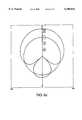
- FIG. 6cis a graph of a beam pattern directed to forty five degrees Northeast by an antenna configured according to the invention.
- FIG. 6dis a graph of beam strength for an antenna configured according to the invention which shows a 9 decibel increase in gain.
- FIG. 1illustrates one cell 50 of a typical CDMA cellular communication system.
- the cell 50represents a geographical area in which mobile subscriber units 60-1 through 60-3 communicate with centrally located base station 160.
- Each subscriber unit 60is equipped with an antenna 100 configured according to this invention.
- the subscriber units 60provide wireless data and/or voice services and can connect devices such as, for example, laptop computers, portable computers, personal digital assistants (PDAs) or the like through base station 160 to a network 75 which can be a Public Switched Telephone Network (PSTN), a packet switched computer network, or other data network such as the Internet or a private intranet.
- PSTNPublic Switched Telephone Network
- packet switched computer networkor other data network such as the Internet or a private intranet.
- the base station 160may communicate with the network 75 over any number of different efficient communication protocols such as primary rate ISDN, or other LAPD based protocols such as IS-634 or V5.2, or even TCP/IP if network 75 is an Ethernet network such as the Internet.
- the subscriber units 101may be mobile in nature and may travel from one location to another while communicating with base station 104.
- FIG. 1illustrates one base station 160 and three mobile subscriber units 60 in cell 50 by way of example only and for ease of description of the invention.
- the inventionis applicable to systems in which there are typically many more subscriber units communicating with one or more base stations in an individual cell, such as cell 50.
- FIG. 1may be a standard cellular type communication system such as a CDMA, TDMA, GSM or other system in which the radio channels are assigned to carry data and/or voice or between the base stations 104 and subscriber units 101.
- FIG. 1is a CDMA-like system, using code division multiplexing principles such as those defined in the IS-95B standards for the air interface.
- the inventionprovides the mobile subscriber units 60 with an antenna 100 that provides directional reception of forward link radio signals transmitted from base station 160, as well as providing directional transmission of reverse link signals, via a process called beamforming, from the mobile subscriber units 60 to the base station 160.
- This conceptis illustrated in FIG. 1 by the example beam patterns 71 through 73 which extend outwardly from each mobile subscriber unit 60 more or less in a direction for best propagation towards the base station 160.
- the antenna apparatus 100reduces the effects of intercell interference and multipath fading for mobile subscriber units 60.
- the transmission beam patterns 71, 72 and 73are extended outward in the direction of the base station 160 but are attenuated in most other directions, less power is required for transmission of effective communication signals from the mobile subscriber units 60-1, 60-2 and 60-3 to the base station 160.
- FIG. 2illustrates a detailed isometric view of a mobile subscriber unit 60 and an associated antenna apparatus 100 configured according to the present invention.
- Antenna apparatus 100includes a platform or housing 110 upon which are mounted five antenna elements 101 through 105. Within housing 110, the antenna apparatus 100 includes phase shifters 111 through 115, a bi-directional summation network or splitter/combiner 120, transceiver 130, and control processor 140 which are all interconnected via bus 135. As illustrated, the antenna apparatus 100 is coupled via the transceiver 130 to a laptop computer 150 (not drawn to scale). The antenna 100 allows the laptop computer 150 to perform wireless data communications via forward link signals 180 transmitted from base station 160 and reverse link signals 170 transmitted to base station 160.
- each antenna element 101 through 105is disposed on the surface of the housing 110 as illustrated in the figure.
- four elements 101, 102, 104 and 105are respectively positioned at locations corresponding to corners of a square, and a fifth antenna element 103 is positioned at a location corresponding to a center of the square.
- the distance between each element 101 through 105is great enough so that the phase relationship between a signal received by more than one element 101 through 105 will be somewhat out of phase with other elements that also receive the same signal, assuming all elements 101 through 105 have the same phase setting as determine by phase shifters 111 through 115. That is, if the phase setting of each element 101 through 105 were the same, each element 101 through 105 would receive the signal somewhat out of phase with the other elements.
- the phase shifters 111 through 115are independently adjustable to affect the directionality of signals to be transmitted and/or received to or from the subscriber unit (i.e., laptop computer 150 in this example).
- the optimal phase setting for sending a reverse link signal 170 from the antenna 100is a phase setting for each antenna element 101 through 105 that creates a directional reverse link signal beamformer. The result is an antenna 100 which directs a stronger reverse link signal pattern in the direction of the intended receiver base station 160.
- the phase settings used for transmissionalso cause the elements 101 to 105 to optimally receive forward link signals 180 that are transmitted from the base station 160. Due to the programmable nature and the independent phase setting of each element 101 through 105, only forward link signals 180 arriving from a direction that is more or less in the location of the base station 160 are optimally received. The elements 101 through 105 naturally reject other signals that are not transmitted from a similar location as are the forward link signals. In other words, a directional antenna is formed by independently adjusting the phase of each element 101 through 105.
- the summation network 120is coupled to the signal terminal 15, of each phase shifter 111 through 115. During transmission, the summation network 120 provides respective reverse link signals to be transmitted by each of the phase shifters 111 through 115.
- the phase shifters 111 through 115shift the phase of the reverse link signal by a phase setting associated with that particular phase shifter 111 through 115, respectively, as set by a phase shift control input, p.
- pphase shift control input
- phase settings used for transmission from each element 101 through 105provide a similar physical effect on a forward link frequency signal 180 that is received from the base station 160. That is, as each element 101 through 105 receives a signal 180 from the base station 160, the respective received signals will initially be out of phase with each other due to the location of each element 101 through 105 upon base 110. However, each received signal is phase-adjusted by the phase shifters 111 through 115. The adjustment brings each signal in phase with the other received signals 180. Accordingly, when each signal is summed by the summation network 120, the composite received signal will be accurate and strong.
- phase control valuesare provided by the controller 140.
- the controller 140determines these optimum phase settings during idle periods when laptop computer 150 is neither transmitting nor receiving data via antenna 100.
- a received signalfor example, a forward link pilot signal 190, that is continuously sent from base station 160 and that is received on each antenna element 101 through 105. That is, during idle periods, the phase shifters 111 through 115 are adjusted to optimize reception of the pilot signal 190 from base station 160, such as by maximizing the received signal energy or other link quality metric.
- the processor 140determines an optimal phase setting for each antenna element 101 through 105 based on an optimized reception of a current pilot signal 190.
- the processor 140then provides and sets the optimal phase for each adjustable phase shifter 111 through 115.
- the phase setting of each phase shifter 111 through 115remains as set during the previous idle time period.
- phase setting computationis based in part on the observation that the location of the base station 160 in relation to any one mobile subscriber unit (i.e., laptop 150) is approximately circumferential in nature. That is, if a circle were drawn around a mobile subscriber unit and different locations are assumed to have a minimum of one degree of granularity between any two locations, the base station 160 can be located at any of a number of different possible angular locations. Assuming accuracy to one degree, for example, there are 360 different possible phase setting combinations that exist for an antenna 100. Each phase setting combination can be thought of as a set of five phase shift values, one for each antenna element 101 through 105.
- the controller 140performs a type of optimized search in which all possible phase setting combinations are tried. For each phase setting (in this case, for each one of the 360 angular settings), five precalculated phase values are read, such as from memory storage locations in the controller 140, and then applied to the respective phase shifters 111 through 115. The response of the receiver 130 is then detected by the controller 140. After testing all possible angles, the one having the best recover response, such as measured by maximum signal to noise ratio (the ratio of energy per bit, E b , or energy per chip, E c , to total interference, I o ).
- maximum signal to noise ratiothe ratio of energy per bit, E b , or energy per chip, E c , to total interference, I o .
- each phase shift valueis individually determined by allowing it to vary while the other phase values are held constant. This perturbational approach iteratively arrives at an optimum value for each of the five phase settings.
- FIG. 3shows steps 301 through 306 performed by the controller 140 according to one embodiment of the invention.
- steps 301 through 306are performed during idle periods of data reception or transmission, such as when a pilot signal 190 is being transmitted by the base station 160.
- step 301the controller 140 determines that the idle mode has been entered, such as by detecting certain forward link signals 180.
- Step 302then begins a loop that will execute once for each possible angle or location at which the base station 160 may be located. In the preferred embodiment, this loop is executed 360 times.
- Step 303programs each phase shifter 111 through 115 with a phase setting corresponding to the first location (i.e., angle 0) setting.
- the phase settingsmay, for example, be precalculated and stored in a table, with five phase shift setting for each possible angle corresponding to the five elements of the array.
- step 303programs phase settings for a first angle, which may be conceptualized as angle 0 in a 360 degree circle surrounding the mobile subscriber unit 60.
- Step 304then measures the received pilot signal 190, as output from the summation network 120.
- the measurement in step 304reflects how well each antenna element 101 through 105 detected the receive pilot signal 190 based upon the current set of programmed phase settings applied in step 303.
- Step 304saves the measurement as a received signal metric value.
- the metricmay, for example, be a link quality metric as bit error rate or noise energy level per chip (E c /N o ).
- Step 305then returns processing to step 302 to program the phase shifters for the next set of phase settings.
- Steps 302 through 305repeat until all 360 sets of phase settings have been programmed into phase shifters 111 through 115 (step 303) and a measurement has been taken of the received pilot signal 190 for each of these settings (Step 304).
- step 306determines the best set of phase settings as determined by which settings produced the strongest receive signal metric value.
- Step 307programs the phase shifters 111 through 115 with the set of phase settings that was determined to produce this best result.
- step 308is executed which repeats the process periodically. Step 308 accounts for the fact that the antenna 100 might be moved and re-oriented during idle periods, thus affecting the direction and orientation of the base station in relation to the antenna 100.
- the antennamay be optimized during transmission.
- steps 301 through 308continuously update and set optimal phase setting for each antenna element 101 through 105.
- FIG. 4shows processing steps for an alternative method for determining the optimal phase setting of antenna elements 101 through 105 is to use a perturbational algorithm.
- this methoduses a perturbational algorithm to determine phase settings in the form of weights for each antenna element 101 through 105.
- step 400one of the antenna elements 101 through 105 is selected.
- step 402the phase settings of the four remaining elements not selected in step 400 are fixed in value.
- step 403then varies the phase setting of the non-fixed element selected in step 401 until the setting which maximizes the pilot signal metric is determined. Then, the process repeats by returning to step 401 where the previously selected element is fixed to this optimum phase and the phase setting of one of the other elements is varied. The process continues until each element is configured with an optimal setting. As the process iterates, the phase settings of each element converge to an optimum setting.
- FIG. 5illustrates a more detailed flow diagram for implementing a perturbational algorithm to determine optimal phase settings for each antenna element.
- the flow diagram in FIG. 5may be used in place of the processing steps performed by the controller 140 in FIG. 3.
- the algorithmfixes a value for four of the five unknown, optimum phase shifts W[i], e.g. W[2] through W[5].
- the algorithmperturbs the system and observes the response, adapting to find the optimum value for the unfixed phase value, e.g. W[1].
- the measured link quality metricin this case E c /I o , is fed to a first gain block G 1 . Again input G is fed to a second gain block G 2 .
- a first fast "clock" date value, CLK1which alternates from a value of "1" to a value of "-1" is inverted by I1 and fed to a first multiplier M1.
- the other input of multiplier M1is fed by the gain block G 2 .
- the output of mlis fed to a second multiplier M2 together with the output of G1.
- An integrator N1measures an average level and provides this to the latch L.
- a slow clock CLK2typically alternating at a rate which varies between "1” and “0” and is much slower than CLK1, by at least 100 times, drives the latch "clock” C.
- the ouput of the latch Lis summed by summation block S with the non-inverted output of M2.
- W[i]is a value which tends to seek a localized minima of the function.
- the process shown in FIG. 5is then repeated by setting the first unfixed phase value W[1] to the derived value, setting W[3] to W[5] to a fixed value and letting w[2] be the output of this process.
- the processcontinues to find optimum values for each of the five unknown phase values.
- the phase setting for each elementcan be stored in a table of vectors, each vector having assignments for the five elements 101 through 105.
- the five values in each vectorcan be computed based upon the angle of arrival of the receive pilot signal. That is, the values for each antenna element are set according to the direction in which the base station is located in relation to the mobile subscriber unit.
- the angle of arrivalcan be used as a value to lookup the proper vector of weights (and/or phase settings) in the table.
- FIG. 6ais a graph of a model of a beam pattern which obtained via an optimal phase setting directed towards a base station located at position corresponding to zero degrees (i.e., to the right of the figure). As illustrated in FIG. 6a, the invention provides a directed signals that helps to avoid the problems of multipath fading and intercell interference.
- FIG. 6bis a graph of another beam pattern model obtained by steering the beam twenty-two degrees north east upon detection of movement of the mobile subscriber unit. As illustrated, by adjusting the phase of each element 101 through 105, the beam may be steered to an optimal position for transmission and for reception of radio signals.
- FIG. 6cis a graph of another beam pattern model obtained by steering the beam twenty-two degrees north east upon detection of movement of the mobile subscriber unit.
- FIG. 6dis a graph of the power gain obtained from the antenna apparatus 100 as compared to the power gain obtained from an omni-directional single element antenna as used in the prior art. As shown, the invention provides a significant increase is the directed power signal by increasing the signal by 9 dB over prior art signal strengths using omnipole antennas.
- the antenna apparatus in preferred embodiments of the inventionis inexpensive to construct and greatly increases the capacity in a CDMA interference limited system. That is, the number of active subscriber units within a single cell in a CDMA system is limited in part by the number of frequencies available for use and by signal interference limitations that occur as the number of frequencies in use increases. As more frequencies become active within a single cell, interference imposes maximum limitations on the number of users who can effectively communicate with the base station. Intercell interference also contributes as a limiting factor is cell capacity.
- this inventionhelps to eliminate interference from adjacent cells and selectively directs transmission and reception of signals from each mobile unit equipped with the invention to and from the base station, an increase in the number of users per cell is realized.
- the inventionreduces the required transmit power for each mobile subscriber unit by providing an extended directed beam towards the base station.
- Alternative physical embodiments of the antennainclude a four element antenna wherein three of the elements are positioned at corners of an equilateral triangular plane and are arranged orthogonally and extend outward from that plane.
- the fourth elementis similarly situated but is located in the center of the triangle.
Landscapes
- Engineering & Computer Science (AREA)
- Computer Networks & Wireless Communication (AREA)
- Mobile Radio Communication Systems (AREA)
- Variable-Direction Aerials And Aerial Arrays (AREA)
Abstract
Description
Claims (14)
Priority Applications (19)
| Application Number | Priority Date | Filing Date | Title |
|---|---|---|---|
| US09/210,117US6100843A (en) | 1998-09-21 | 1998-12-11 | Adaptive antenna for use in same frequency networks |
| CA002344822ACA2344822A1 (en) | 1998-09-21 | 1999-09-09 | Adaptive antenna for use in same frequency networks |
| KR1020017003617AKR100727860B1 (en) | 1998-09-21 | 1999-09-09 | Adaptive antenna for use in same frequency networks |
| PCT/US1999/020691WO2000017958A1 (en) | 1998-09-21 | 1999-09-09 | Adaptive antenna for use in same frequency networks |
| AU59152/99AAU5915299A (en) | 1998-09-21 | 1999-09-09 | Adaptive antenna for use in same frequency networks |
| US09/579,084US6304215B1 (en) | 1998-09-21 | 2000-05-25 | Method of use for an adaptive antenna in same frequency networks |
| US09/616,588US6404386B1 (en) | 1998-09-21 | 2000-07-14 | Adaptive antenna for use in same frequency networks |
| US09/776,396US6792290B2 (en) | 1998-09-21 | 2001-02-02 | Method and apparatus for performing directional re-scan of an adaptive antenna |
| US09/776,397US6400317B2 (en) | 1998-09-21 | 2001-02-02 | Method and apparatus for antenna control in a communications network |
| US09/776,558US6473036B2 (en) | 1998-09-21 | 2001-02-02 | Method and apparatus for adapting antenna array to reduce adaptation time while increasing array performance |
| US09/859,001US6600456B2 (en) | 1998-09-21 | 2001-05-16 | Adaptive antenna for use in wireless communication systems |
| US09/942,257US6518920B2 (en) | 1998-09-21 | 2001-08-28 | Adaptive antenna for use in same frequency networks |
| US10/282,928US6933887B2 (en) | 1998-09-21 | 2002-10-28 | Method and apparatus for adapting antenna array using received predetermined signal |
| US10/744,912US6989797B2 (en) | 1998-09-21 | 2003-12-23 | Adaptive antenna for use in wireless communication systems |
| US10/914,982US7009559B2 (en) | 1998-09-21 | 2004-08-10 | Method and apparatus for adapting antenna array using received predetermined signal |
| US10/937,792US7289827B2 (en) | 1998-09-21 | 2004-09-09 | Method and apparatus for performing directional re-scan of an adaptive antenna |
| US11/332,901US7215297B2 (en) | 1998-09-21 | 2006-01-17 | Adaptive antenna for use in wireless communication systems |
| US11/800,949US7528789B2 (en) | 1998-09-21 | 2007-05-08 | Adaptive antenna for use in wireless communication systems |
| US12/435,557US20090284434A1 (en) | 1998-09-21 | 2009-05-05 | Adaptive antenna for use in wireless communication systems |
Applications Claiming Priority (2)
| Application Number | Priority Date | Filing Date | Title |
|---|---|---|---|
| US15773698A | 1998-09-21 | 1998-09-21 | |
| US09/210,117US6100843A (en) | 1998-09-21 | 1998-12-11 | Adaptive antenna for use in same frequency networks |
Related Parent Applications (1)
| Application Number | Title | Priority Date | Filing Date |
|---|---|---|---|
| US15773698AContinuation | 1998-09-21 | 1998-09-21 |
Related Child Applications (2)
| Application Number | Title | Priority Date | Filing Date |
|---|---|---|---|
| US09/579,084DivisionUS6304215B1 (en) | 1998-09-21 | 2000-05-25 | Method of use for an adaptive antenna in same frequency networks |
| US09/859,001DivisionUS6600456B2 (en) | 1998-09-21 | 2001-05-16 | Adaptive antenna for use in wireless communication systems |
Publications (1)
| Publication Number | Publication Date |
|---|---|
| US6100843Atrue US6100843A (en) | 2000-08-08 |
Family
ID=26854438
Family Applications (3)
| Application Number | Title | Priority Date | Filing Date |
|---|---|---|---|
| US09/210,117Expired - LifetimeUS6100843A (en) | 1998-09-21 | 1998-12-11 | Adaptive antenna for use in same frequency networks |
| US09/579,084Expired - LifetimeUS6304215B1 (en) | 1998-09-21 | 2000-05-25 | Method of use for an adaptive antenna in same frequency networks |
| US09/942,257Expired - Fee RelatedUS6518920B2 (en) | 1998-09-21 | 2001-08-28 | Adaptive antenna for use in same frequency networks |
Family Applications After (2)
| Application Number | Title | Priority Date | Filing Date |
|---|---|---|---|
| US09/579,084Expired - LifetimeUS6304215B1 (en) | 1998-09-21 | 2000-05-25 | Method of use for an adaptive antenna in same frequency networks |
| US09/942,257Expired - Fee RelatedUS6518920B2 (en) | 1998-09-21 | 2001-08-28 | Adaptive antenna for use in same frequency networks |
Country Status (5)
| Country | Link |
|---|---|
| US (3) | US6100843A (en) |
| KR (1) | KR100727860B1 (en) |
| AU (1) | AU5915299A (en) |
| CA (1) | CA2344822A1 (en) |
| WO (1) | WO2000017958A1 (en) |
Cited By (58)
| Publication number | Priority date | Publication date | Assignee | Title |
|---|---|---|---|---|
| US6304215B1 (en)* | 1998-09-21 | 2001-10-16 | Tantivy Communications, Inc. | Method of use for an adaptive antenna in same frequency networks |
| US6332072B1 (en)* | 1999-05-24 | 2001-12-18 | Motorola, Inc. | Method and apparatus for detecting failures in a communication device BV signal metrics |
| WO2002039543A1 (en)* | 2000-11-10 | 2002-05-16 | Am Group Corporation | Direction-agile antenna system for wireless communications |
| US6400317B2 (en) | 1998-09-21 | 2002-06-04 | Tantivy Communications, Inc. | Method and apparatus for antenna control in a communications network |
| US6404386B1 (en)* | 1998-09-21 | 2002-06-11 | Tantivy Communications, Inc. | Adaptive antenna for use in same frequency networks |
| US20020136274A1 (en)* | 2000-02-23 | 2002-09-26 | Tantivy Communications, Inc. | Method for searching pilot signals to synchronize a CDMA receiver with an associated transmitter |
| US6473036B2 (en) | 1998-09-21 | 2002-10-29 | Tantivy Communications, Inc. | Method and apparatus for adapting antenna array to reduce adaptation time while increasing array performance |
| US6476773B2 (en) | 2000-08-18 | 2002-11-05 | Tantivy Communications, Inc. | Printed or etched, folding, directional antenna |
| US6515635B2 (en) | 2000-09-22 | 2003-02-04 | Tantivy Communications, Inc. | Adaptive antenna for use in wireless communication systems |
| US6525696B2 (en) | 2000-12-20 | 2003-02-25 | Radio Frequency Systems, Inc. | Dual band antenna using a single column of elliptical vivaldi notches |
| US6529166B2 (en) | 2000-09-22 | 2003-03-04 | Sarnoff Corporation | Ultra-wideband multi-beam adaptive antenna |
| US20030048800A1 (en)* | 2001-03-30 | 2003-03-13 | Daniel B. Kilfoyle | Mutlistage reception of code division multiple access transmissions |
| US20030048770A1 (en)* | 2001-09-13 | 2003-03-13 | Tantivy Communications, Inc. | Method of detection of signals using an adaptive antenna in a peer-to-peer network |
| WO2003041224A1 (en)* | 2001-11-09 | 2003-05-15 | Tantivy Communications, Inc. | A dual band phased array employing spatial second harmonics |
| US6600456B2 (en)* | 1998-09-21 | 2003-07-29 | Tantivy Communications, Inc. | Adaptive antenna for use in wireless communication systems |
| US20040009794A1 (en)* | 2002-03-08 | 2004-01-15 | Tantivy Communications, Inc. | Antenna adaptation comparison method for high mobility |
| US20040033817A1 (en)* | 2002-03-01 | 2004-02-19 | Tantivy Communications, Inc. | Intelligent interface for controlling an adaptive antenna array |
| US6792290B2 (en) | 1998-09-21 | 2004-09-14 | Ipr Licensing, Inc. | Method and apparatus for performing directional re-scan of an adaptive antenna |
| US20040246176A1 (en)* | 2003-06-04 | 2004-12-09 | Farrokh Mohamadi | Phase management for beam-forming applications |
| US20040259597A1 (en)* | 1998-09-21 | 2004-12-23 | Gothard Griffin K. | Adaptive antenna for use in wireless communication systems |
| US20050012654A1 (en)* | 2003-07-15 | 2005-01-20 | Farrokh Mohamadi | Beacon-on-demand radar transponder |
| US20050037822A1 (en)* | 2003-06-19 | 2005-02-17 | Ipr Licensing, Inc. | Antenna steering method and apparatus for an 802.11 station |
| US20050062649A1 (en)* | 2001-05-10 | 2005-03-24 | Ipr Licensing, Inc. | Folding directional antenna |
| US20050068231A1 (en)* | 1998-09-21 | 2005-03-31 | Ipr Licensing, Inc. | Method and apparatus for adapting antenna array using received perdetermined signal |
| US20050078047A1 (en)* | 2001-06-12 | 2005-04-14 | Ipr Licensing, Inc. | Method and apparatus for frequency selective beam forming |
| US20050176385A1 (en)* | 2004-02-05 | 2005-08-11 | Interdigital Technology Corporation | Method for performing measurements for handoff of a mobile unit operating with a switched beam antenna in a wireless communication system, and corresponding system |
| US20050181733A1 (en)* | 2004-02-06 | 2005-08-18 | Interdigital Technology Corporation | Method and apparatus for measuring channel quality using a smart antenna in a wireless transmit/receive unit |
| US20050227748A1 (en)* | 2004-04-13 | 2005-10-13 | Airgain, Inc. | Direction-agile antenna controller |
| US20050285784A1 (en)* | 2004-06-03 | 2005-12-29 | Interdigital Technology Corporation | Satellite communication subscriber device with a smart antenna and associated method |
| US6987745B1 (en)* | 1999-10-26 | 2006-01-17 | Koninklijke Philips Electronics N.V. | Control of multidirectional antenna structure in a primary station for use in a radio communication network |
| US20060057977A1 (en)* | 2004-09-15 | 2006-03-16 | Aviation Communication & Surveillance Systems Llc | Pulse transmitters having multiple outputs in phase relationship and methods of operation |
| US20060077927A1 (en)* | 2001-09-17 | 2006-04-13 | Kilfoyle Daniel B | Method and system for a channel selective repeater with capacity enhancement in a spread-spectrum wireless network |
| US7031652B2 (en) | 2001-02-05 | 2006-04-18 | Soma Networks, Inc. | Wireless local loop antenna |
| US20060214836A1 (en)* | 2005-03-24 | 2006-09-28 | Izhak Baharav | System and method for pattern design in microwave programmable arrays |
| US20060214833A1 (en)* | 2005-03-24 | 2006-09-28 | Izhak Baharav | System and method for microwave imaging using an interleaved pattern in a programmable reflector array |
| US20060292991A1 (en)* | 2000-11-10 | 2006-12-28 | Abramov Oleg Y | Dynamically optimized smart antenna system |
| US20070152893A1 (en)* | 2002-02-01 | 2007-07-05 | Ipr Licensing, Inc. | Aperiodic array antenna |
| US20070189325A1 (en)* | 2002-09-30 | 2007-08-16 | Ipr Licensing, Inc. | Method and apparatus for antenna steering for WLAN |
| KR100770854B1 (en) | 2000-11-13 | 2007-10-26 | 삼성전자주식회사 | portable terminal |
| US20080174473A1 (en)* | 2004-09-15 | 2008-07-24 | Smith Mark D | Systems and methods for using a TCAS directional antenna for omnidirectional transmission |
| US20090023401A1 (en)* | 2004-02-06 | 2009-01-22 | Interdigital Technology Corporation | Method and apparatus for reducing transient impacts of beam switching in a switched beam antenna system |
| US20090092158A1 (en)* | 2007-06-06 | 2009-04-09 | Hossein Izadpanah | Multi-aperture Three-Dimensional Beamforming |
| US7535867B1 (en) | 2001-02-02 | 2009-05-19 | Science Applications International Corporation | Method and system for a remote downlink transmitter for increasing the capacity and downlink capability of a multiple access interference limited spread-spectrum wireless network |
| US7746830B2 (en) | 1998-06-01 | 2010-06-29 | Interdigital Technology Corporation | System and method for maintaining wireless channels over a reverse link of a CDMA wireless communication system |
| US7773566B2 (en) | 1998-06-01 | 2010-08-10 | Tantivy Communications, Inc. | System and method for maintaining timing of synchronization messages over a reverse link of a CDMA wireless communication system |
| US7936728B2 (en) | 1997-12-17 | 2011-05-03 | Tantivy Communications, Inc. | System and method for maintaining timing of synchronization messages over a reverse link of a CDMA wireless communication system |
| US8134980B2 (en) | 1998-06-01 | 2012-03-13 | Ipr Licensing, Inc. | Transmittal of heartbeat signal at a lower level than heartbeat request |
| US8155096B1 (en) | 2000-12-01 | 2012-04-10 | Ipr Licensing Inc. | Antenna control system and method |
| US8175120B2 (en) | 2000-02-07 | 2012-05-08 | Ipr Licensing, Inc. | Minimal maintenance link to support synchronization |
| US8274954B2 (en) | 2001-02-01 | 2012-09-25 | Ipr Licensing, Inc. | Alternate channel for carrying selected message types |
| US8422540B1 (en) | 2012-06-21 | 2013-04-16 | CBF Networks, Inc. | Intelligent backhaul radio with zero division duplexing |
| US8467363B2 (en) | 2011-08-17 | 2013-06-18 | CBF Networks, Inc. | Intelligent backhaul radio and antenna system |
| US8638877B2 (en) | 2001-02-01 | 2014-01-28 | Intel Corporation | Methods, apparatuses and systems for selective transmission of traffic data using orthogonal sequences |
| US9014118B2 (en) | 2001-06-13 | 2015-04-21 | Intel Corporation | Signaling for wireless communications |
| US9042400B2 (en) | 1997-12-17 | 2015-05-26 | Intel Corporation | Multi-detection of heartbeat to reduce error probability |
| US9525923B2 (en) | 1997-12-17 | 2016-12-20 | Intel Corporation | Multi-detection of heartbeat to reduce error probability |
| US10470095B2 (en) | 2013-01-13 | 2019-11-05 | Qualcomm Incorporated | Method for air-to-ground data link antenna self calibration |
| US11342981B2 (en) | 2018-09-10 | 2022-05-24 | Samsung Electronics Co., Ltd. | Electronic device including antenna module |
Families Citing this family (90)
| Publication number | Priority date | Publication date | Assignee | Title |
|---|---|---|---|---|
| US6778507B1 (en)* | 1999-09-01 | 2004-08-17 | Qualcomm Incorporated | Method and apparatus for beamforming in a wireless communication system |
| US20020118783A1 (en)* | 2001-02-26 | 2002-08-29 | Peter Cripps | Smart antenna based spectrum multiplexing using a pilot signal |
| US7164329B2 (en) | 2001-04-11 | 2007-01-16 | Kyocera Wireless Corp. | Tunable phase shifer with a control signal generator responsive to DC offset in a mixed signal |
| US7174147B2 (en)* | 2001-04-11 | 2007-02-06 | Kyocera Wireless Corp. | Bandpass filter with tunable resonator |
| US7221243B2 (en)* | 2001-04-11 | 2007-05-22 | Kyocera Wireless Corp. | Apparatus and method for combining electrical signals |
| US7746292B2 (en)* | 2001-04-11 | 2010-06-29 | Kyocera Wireless Corp. | Reconfigurable radiation desensitivity bracket systems and methods |
| US7394430B2 (en)* | 2001-04-11 | 2008-07-01 | Kyocera Wireless Corp. | Wireless device reconfigurable radiation desensitivity bracket systems and methods |
| US6690251B2 (en)* | 2001-04-11 | 2004-02-10 | Kyocera Wireless Corporation | Tunable ferro-electric filter |
| US7154440B2 (en)* | 2001-04-11 | 2006-12-26 | Kyocera Wireless Corp. | Phase array antenna using a constant-gain phase shifter |
| US8249187B2 (en) | 2002-05-09 | 2012-08-21 | Google Inc. | System, method and apparatus for mobile transmit diversity using symmetric phase difference |
| DE60230981D1 (en)* | 2001-05-31 | 2009-03-12 | Magnolia Broadband Inc | COMMUNICATION DEVICE WITH INTELLIGENT ANTENNA USING A QUALITY DISPLAY SIGNAL |
| US6448938B1 (en)* | 2001-06-12 | 2002-09-10 | Tantivy Communications, Inc. | Method and apparatus for frequency selective beam forming |
| US7437159B1 (en)* | 2001-06-21 | 2008-10-14 | Sprint Spectrum L.P. | Method and system for overcoming pilot pollution in a wireless communications network |
| US7071776B2 (en) | 2001-10-22 | 2006-07-04 | Kyocera Wireless Corp. | Systems and methods for controlling output power in a communication device |
| US6690223B1 (en)* | 2001-12-27 | 2004-02-10 | Bay Microsystems, Inc. | System and method for shifting the phase of a clock signal |
| DE60225238T2 (en)* | 2002-01-15 | 2009-05-07 | Koninklijke Kpn N.V. | Method and system for planning and / or estimating cell capacity in CDMA radio networks |
| US7176845B2 (en)* | 2002-02-12 | 2007-02-13 | Kyocera Wireless Corp. | System and method for impedance matching an antenna to sub-bands in a communication band |
| US7184727B2 (en)* | 2002-02-12 | 2007-02-27 | Kyocera Wireless Corp. | Full-duplex antenna system and method |
| US7180467B2 (en)* | 2002-02-12 | 2007-02-20 | Kyocera Wireless Corp. | System and method for dual-band antenna matching |
| JP2003243996A (en)* | 2002-02-18 | 2003-08-29 | Seiko Instruments Inc | Data telegraphic transmitter |
| KR20070054754A (en)* | 2002-09-30 | 2007-05-29 | 아이피알 라이센싱, 인코포레이티드 | Directional Antenna Coordination in the Physical Layer of WLAN |
| US7106569B2 (en)* | 2002-11-27 | 2006-09-12 | Sierra Wireless, Inc. | Adaptive current limiter for wireless modem |
| US7286844B1 (en) | 2003-01-31 | 2007-10-23 | Bbn Technologies Corp. | Systems and methods for three dimensional antenna selection and power control in an Ad-Hoc wireless network |
| US7085541B2 (en)* | 2003-01-31 | 2006-08-01 | Bbnt Solutions Llc | Systems and methods for directional antenna power control in a wireless network |
| JP4247019B2 (en) | 2003-03-24 | 2009-04-02 | 京セラ株式会社 | Wireless communication device |
| US7720443B2 (en) | 2003-06-02 | 2010-05-18 | Kyocera Wireless Corp. | System and method for filtering time division multiple access telephone communications |
| US7379506B2 (en)* | 2003-09-23 | 2008-05-27 | Nokia Corporation | Apparatus, and associated method, for assigning data to transmit antennas of a multiple transmit antenna transmitter |
| MXPA06003804A (en)* | 2003-11-24 | 2006-06-14 | Interdigital Tech Corp | METHOD AND APPLIANCE TO USE A DIRECTIONAL BEAM ANTENNA IN A WIRELESS TRANSMISSION / RECEPTION UNIT. |
| US7272359B2 (en) | 2004-01-26 | 2007-09-18 | Magnolia Broadband Inc. | Communicating signals according to a quality indicator using multiple antenna elements |
| US7340254B2 (en)* | 2004-02-05 | 2008-03-04 | Interdigital Technology Corporation | Measurement opportunities for a mobile unit operating with a switched beam antenna in a CDMA system |
| US7308264B2 (en)* | 2004-02-05 | 2007-12-11 | Interdigital Technology Corporation | Method for identifying pre-candidate cells for a mobile unit operating with a switched beam antenna in a wireless communication system, and corresponding system |
| US7324817B2 (en)* | 2004-02-07 | 2008-01-29 | Interdigital Technology Corporation | Wireless communication method and apparatus for selecting and reselecting cells based on measurements performed using directional beams and an omni-directional beam pattern |
| US7432855B2 (en)* | 2004-06-03 | 2008-10-07 | Farrokh Mohamadi | RFID reader and active tag |
| US7248845B2 (en)* | 2004-07-09 | 2007-07-24 | Kyocera Wireless Corp. | Variable-loss transmitter and method of operation |
| US7696946B2 (en) | 2004-08-18 | 2010-04-13 | Ruckus Wireless, Inc. | Reducing stray capacitance in antenna element switching |
| US7880683B2 (en) | 2004-08-18 | 2011-02-01 | Ruckus Wireless, Inc. | Antennas with polarization diversity |
| US7933628B2 (en) | 2004-08-18 | 2011-04-26 | Ruckus Wireless, Inc. | Transmission and reception parameter control |
| US7362280B2 (en)* | 2004-08-18 | 2008-04-22 | Ruckus Wireless, Inc. | System and method for a minimized antenna apparatus with selectable elements |
| US8031129B2 (en) | 2004-08-18 | 2011-10-04 | Ruckus Wireless, Inc. | Dual band dual polarization antenna array |
| US7899497B2 (en)* | 2004-08-18 | 2011-03-01 | Ruckus Wireless, Inc. | System and method for transmission parameter control for an antenna apparatus with selectable elements |
| US7292198B2 (en)* | 2004-08-18 | 2007-11-06 | Ruckus Wireless, Inc. | System and method for an omnidirectional planar antenna apparatus with selectable elements |
| US7652632B2 (en)* | 2004-08-18 | 2010-01-26 | Ruckus Wireless, Inc. | Multiband omnidirectional planar antenna apparatus with selectable elements |
| US7498996B2 (en)* | 2004-08-18 | 2009-03-03 | Ruckus Wireless, Inc. | Antennas with polarization diversity |
| US7965252B2 (en)* | 2004-08-18 | 2011-06-21 | Ruckus Wireless, Inc. | Dual polarization antenna array with increased wireless coverage |
| US7193562B2 (en) | 2004-11-22 | 2007-03-20 | Ruckus Wireless, Inc. | Circuit board having a peripheral antenna apparatus with selectable antenna elements |
| US8619662B2 (en)* | 2004-11-05 | 2013-12-31 | Ruckus Wireless, Inc. | Unicast to multicast conversion |
| US9240868B2 (en) | 2004-11-05 | 2016-01-19 | Ruckus Wireless, Inc. | Increasing reliable data throughput in a wireless network |
| US8638708B2 (en)* | 2004-11-05 | 2014-01-28 | Ruckus Wireless, Inc. | MAC based mapping in IP based communications |
| US7505447B2 (en) | 2004-11-05 | 2009-03-17 | Ruckus Wireless, Inc. | Systems and methods for improved data throughput in communications networks |
| CN1934750B (en)* | 2004-11-22 | 2012-07-18 | 鲁库斯无线公司 | Circuit board having a peripheral antenna apparatus with selectable antenna elements |
| US8792414B2 (en)* | 2005-07-26 | 2014-07-29 | Ruckus Wireless, Inc. | Coverage enhancement using dynamic antennas |
| US7358912B1 (en) | 2005-06-24 | 2008-04-15 | Ruckus Wireless, Inc. | Coverage antenna apparatus with selectable horizontal and vertical polarization elements |
| US8145201B2 (en) | 2004-12-17 | 2012-03-27 | Raytheon Bbn Technologies Corp. | Methods and apparatus for reduced energy communication in an ad hoc network |
| US7893882B2 (en) | 2007-01-08 | 2011-02-22 | Ruckus Wireless, Inc. | Pattern shaping of RF emission patterns |
| US7646343B2 (en) | 2005-06-24 | 2010-01-12 | Ruckus Wireless, Inc. | Multiple-input multiple-output wireless antennas |
| US7132989B1 (en) | 2005-05-04 | 2006-11-07 | Kyocera Wireless Corp. | Apparatus, system, and method for adjusting antenna characteristics using tunable parasitic elements |
| US7548762B2 (en)* | 2005-11-30 | 2009-06-16 | Kyocera Corporation | Method for tuning a GPS antenna matching network |
| EP1958369B1 (en) | 2005-12-01 | 2015-04-08 | Ruckus Wireless, Inc. | On-demand services by wireless base station virtualization |
| US7847740B2 (en)* | 2006-02-13 | 2010-12-07 | Kyocera Corporation | Antenna system having receiver antenna diversity and configurable transmission antenna and method of management thereof |
| EP2013758B1 (en)* | 2006-04-24 | 2016-08-03 | Ruckus Wireless, Inc. | Dynamic authentication in secured wireless networks |
| US9769655B2 (en) | 2006-04-24 | 2017-09-19 | Ruckus Wireless, Inc. | Sharing security keys with headless devices |
| US9071583B2 (en)* | 2006-04-24 | 2015-06-30 | Ruckus Wireless, Inc. | Provisioned configuration for automatic wireless connection |
| US7639106B2 (en)* | 2006-04-28 | 2009-12-29 | Ruckus Wireless, Inc. | PIN diode network for multiband RF coupling |
| US20070293178A1 (en)* | 2006-05-23 | 2007-12-20 | Darin Milton | Antenna Control |
| US8670725B2 (en) | 2006-08-18 | 2014-03-11 | Ruckus Wireless, Inc. | Closed-loop automatic channel selection |
| US7924728B2 (en) | 2006-08-25 | 2011-04-12 | Raytheon Bbn Technologies Corp | Systems and methods for energy-conscious communication in wireless ad-hoc networks |
| US8547899B2 (en) | 2007-07-28 | 2013-10-01 | Ruckus Wireless, Inc. | Wireless network throughput enhancement through channel aware scheduling |
| US8149716B2 (en) | 2007-08-20 | 2012-04-03 | Raytheon Bbn Technologies Corp. | Systems and methods for adaptive routing in mobile ad-hoc networks and disruption tolerant networks |
| US8086203B2 (en)* | 2007-11-26 | 2011-12-27 | Broadcom Corporation | Method and system for wireless local area network (WLAN) phase shifter training |
| US8355343B2 (en) | 2008-01-11 | 2013-01-15 | Ruckus Wireless, Inc. | Determining associations in a mesh network |
| WO2010071300A2 (en)* | 2008-12-19 | 2010-06-24 | 엘지전자주식회사 | Method and apparatus for reference signal transmission in wireless communication system |
| US8217843B2 (en) | 2009-03-13 | 2012-07-10 | Ruckus Wireless, Inc. | Adjustment of radiation patterns utilizing a position sensor |
| US8698675B2 (en) | 2009-05-12 | 2014-04-15 | Ruckus Wireless, Inc. | Mountable antenna elements for dual band antenna |
| JP5347889B2 (en)* | 2009-10-09 | 2013-11-20 | 株式会社リコー | Wireless communication apparatus, image processing apparatus, and wireless communication method |
| US9979626B2 (en) | 2009-11-16 | 2018-05-22 | Ruckus Wireless, Inc. | Establishing a mesh network with wired and wireless links |
| WO2011060454A2 (en)* | 2009-11-16 | 2011-05-19 | Ruckus Wireless, Inc. | Establishing a mesh network with wired and wireless links |
| US9407012B2 (en) | 2010-09-21 | 2016-08-02 | Ruckus Wireless, Inc. | Antenna with dual polarization and mountable antenna elements |
| CN103858106B (en) | 2011-05-01 | 2017-04-26 | 鲁库斯无线公司 | remote cable access point reset |
| US9645222B2 (en) | 2011-08-08 | 2017-05-09 | Trimble Navigation Limited | Apparatus for direction finding of wireless signals |
| US8756668B2 (en) | 2012-02-09 | 2014-06-17 | Ruckus Wireless, Inc. | Dynamic PSK for hotspots |
| US10186750B2 (en) | 2012-02-14 | 2019-01-22 | Arris Enterprises Llc | Radio frequency antenna array with spacing element |
| US9634403B2 (en) | 2012-02-14 | 2017-04-25 | Ruckus Wireless, Inc. | Radio frequency emission pattern shaping |
| US9092610B2 (en) | 2012-04-04 | 2015-07-28 | Ruckus Wireless, Inc. | Key assignment for a brand |
| US9100974B2 (en) | 2012-04-12 | 2015-08-04 | Fidelity Comtech, Inc. | System for continuously improving the performance of wireless networks with mobile users |
| US8306479B1 (en)* | 2012-07-06 | 2012-11-06 | Metropcs Wireless, Inc. | Polarization control for cell telecommunication system |
| US9648502B2 (en) | 2012-08-15 | 2017-05-09 | Trimble Navigation Limited | System for tailoring wireless coverage to a geographic area |
| US9570799B2 (en) | 2012-09-07 | 2017-02-14 | Ruckus Wireless, Inc. | Multiband monopole antenna apparatus with ground plane aperture |
| CN105051975B (en) | 2013-03-15 | 2019-04-19 | 艾锐势有限责任公司 | Low-frequency band reflector for double frequency-band directional aerial |
| EP3251169A1 (en)* | 2015-01-29 | 2017-12-06 | Telefonaktiebolaget LM Ericsson (publ) | Reduced gain of an antenna beam pattern |
| CN110611916A (en)* | 2018-05-28 | 2019-12-24 | 中国移动通信集团广东有限公司 | Method and device for detecting cell coverage change |
Citations (18)
| Publication number | Priority date | Publication date | Assignee | Title |
|---|---|---|---|---|
| DE2812575A1 (en)* | 1978-03-22 | 1979-09-27 | Siemens Ag | Phase controlled antenna array - uses transmitters, each with pilot control circuit with phase discriminator and adjustable phase shifter |
| US4170766A (en)* | 1978-01-27 | 1979-10-09 | Raytheon Company | Beamformer |
| JPS5950603A (en)* | 1982-09-17 | 1984-03-23 | Nec Corp | Transmission signal system |
| US4488155A (en)* | 1982-07-30 | 1984-12-11 | The United States Of America As Represented By The Administrator Of The National Aeronautics And Space Administration | Method and apparatus for self-calibration and phasing of array antenna |
| US5038149A (en)* | 1988-12-16 | 1991-08-06 | Thomson-Csf | Antenna with three-dimensional coverage and electronic scanning, of the random spare volume array type |
| US5117236A (en)* | 1990-10-19 | 1992-05-26 | Motorola, Inc. | Antenna pattern selection for optimized communications |
| US5280472A (en)* | 1990-12-07 | 1994-01-18 | Qualcomm Incorporated | CDMA microcellular telephone system and distributed antenna system therefor |
| US5303240A (en)* | 1991-07-08 | 1994-04-12 | Motorola, Inc. | Telecommunications system using directional antennas |
| US5430452A (en)* | 1990-06-19 | 1995-07-04 | Thomson-Csf | Device for supply to the radiating elements of an array antenna, and application thereof to an antenna of an MLS type landing system |
| US5437055A (en)* | 1993-06-03 | 1995-07-25 | Qualcomm Incorporated | Antenna system for multipath diversity in an indoor microcellular communication system |
| US5502447A (en)* | 1993-10-28 | 1996-03-26 | Hazeltine Corporation | Beam sharpened pencil beam antenna systems |
| US5592178A (en)* | 1994-06-01 | 1997-01-07 | Raytheon Company | Wideband interference suppressor in a phased array radar |
| US5617102A (en)* | 1994-11-18 | 1997-04-01 | At&T Global Information Solutions Company | Communications transceiver using an adaptive directional antenna |
| US5621752A (en)* | 1994-06-23 | 1997-04-15 | Qualcomm Incorporated | Adaptive sectorization in a spread spectrum communication system |
| US5634199A (en)* | 1993-04-14 | 1997-05-27 | Stanford University | Method of subspace beamforming using adaptive transmitting antennas with feedback |
| US5680142A (en)* | 1995-11-07 | 1997-10-21 | Smith; David Anthony | Communication system and method utilizing an antenna having adaptive characteristics |
| US5739784A (en)* | 1995-11-20 | 1998-04-14 | Motorola, Inc. | Method and beam stepping apparatus for a satellite cellular communication system |
| US5943362A (en)* | 1994-06-23 | 1999-08-24 | Kabushiki Kaisha Toshiba | Spread spectrum radio communication system |
Family Cites Families (8)
| Publication number | Priority date | Publication date | Assignee | Title |
|---|---|---|---|---|
| US5017927A (en)* | 1990-02-20 | 1991-05-21 | General Electric Company | Monopulse phased array antenna with plural transmit-receive module phase shifters |
| US6131022A (en)* | 1994-06-29 | 2000-10-10 | Martin Marietta Corporation | Transceiver and antenna system for communication with remote station |
| KR100239177B1 (en) | 1997-08-30 | 2000-01-15 | 윤종용 | Smart antenna receiving apparatus and method using pilot signal in cdma mobile communication system |
| US5991643A (en) | 1997-11-28 | 1999-11-23 | Acer Peripherals, Inc. | Radio transceiver having switchable antennas |
| US5990830A (en)* | 1998-08-24 | 1999-11-23 | Harris Corporation | Serial pipelined phase weight generator for phased array antenna having subarray controller delay equalization |
| US6125137A (en)* | 1998-09-11 | 2000-09-26 | Motorola, Inc. | Apparatus and method for performing a signal search in a coherent wireless communication system |
| US6362790B1 (en) | 1998-09-18 | 2002-03-26 | Tantivy Communications, Inc. | Antenna array structure stacked over printed wiring board with beamforming components |
| US6100843A (en)* | 1998-09-21 | 2000-08-08 | Tantivy Communications Inc. | Adaptive antenna for use in same frequency networks |
- 1998
- 1998-12-11USUS09/210,117patent/US6100843A/ennot_activeExpired - Lifetime
- 1999
- 1999-09-09CACA002344822Apatent/CA2344822A1/ennot_activeAbandoned
- 1999-09-09KRKR1020017003617Apatent/KR100727860B1/ennot_activeExpired - Fee Related
- 1999-09-09WOPCT/US1999/020691patent/WO2000017958A1/enactiveIP Right Grant
- 1999-09-09AUAU59152/99Apatent/AU5915299A/ennot_activeAbandoned
- 2000
- 2000-05-25USUS09/579,084patent/US6304215B1/ennot_activeExpired - Lifetime
- 2001
- 2001-08-28USUS09/942,257patent/US6518920B2/ennot_activeExpired - Fee Related
Patent Citations (18)
| Publication number | Priority date | Publication date | Assignee | Title |
|---|---|---|---|---|
| US4170766A (en)* | 1978-01-27 | 1979-10-09 | Raytheon Company | Beamformer |
| DE2812575A1 (en)* | 1978-03-22 | 1979-09-27 | Siemens Ag | Phase controlled antenna array - uses transmitters, each with pilot control circuit with phase discriminator and adjustable phase shifter |
| US4488155A (en)* | 1982-07-30 | 1984-12-11 | The United States Of America As Represented By The Administrator Of The National Aeronautics And Space Administration | Method and apparatus for self-calibration and phasing of array antenna |
| JPS5950603A (en)* | 1982-09-17 | 1984-03-23 | Nec Corp | Transmission signal system |
| US5038149A (en)* | 1988-12-16 | 1991-08-06 | Thomson-Csf | Antenna with three-dimensional coverage and electronic scanning, of the random spare volume array type |
| US5430452A (en)* | 1990-06-19 | 1995-07-04 | Thomson-Csf | Device for supply to the radiating elements of an array antenna, and application thereof to an antenna of an MLS type landing system |
| US5117236A (en)* | 1990-10-19 | 1992-05-26 | Motorola, Inc. | Antenna pattern selection for optimized communications |
| US5280472A (en)* | 1990-12-07 | 1994-01-18 | Qualcomm Incorporated | CDMA microcellular telephone system and distributed antenna system therefor |
| US5303240A (en)* | 1991-07-08 | 1994-04-12 | Motorola, Inc. | Telecommunications system using directional antennas |
| US5634199A (en)* | 1993-04-14 | 1997-05-27 | Stanford University | Method of subspace beamforming using adaptive transmitting antennas with feedback |
| US5437055A (en)* | 1993-06-03 | 1995-07-25 | Qualcomm Incorporated | Antenna system for multipath diversity in an indoor microcellular communication system |
| US5502447A (en)* | 1993-10-28 | 1996-03-26 | Hazeltine Corporation | Beam sharpened pencil beam antenna systems |
| US5592178A (en)* | 1994-06-01 | 1997-01-07 | Raytheon Company | Wideband interference suppressor in a phased array radar |
| US5621752A (en)* | 1994-06-23 | 1997-04-15 | Qualcomm Incorporated | Adaptive sectorization in a spread spectrum communication system |
| US5943362A (en)* | 1994-06-23 | 1999-08-24 | Kabushiki Kaisha Toshiba | Spread spectrum radio communication system |
| US5617102A (en)* | 1994-11-18 | 1997-04-01 | At&T Global Information Solutions Company | Communications transceiver using an adaptive directional antenna |
| US5680142A (en)* | 1995-11-07 | 1997-10-21 | Smith; David Anthony | Communication system and method utilizing an antenna having adaptive characteristics |
| US5739784A (en)* | 1995-11-20 | 1998-04-14 | Motorola, Inc. | Method and beam stepping apparatus for a satellite cellular communication system |
Cited By (132)
| Publication number | Priority date | Publication date | Assignee | Title |
|---|---|---|---|---|
| US9525923B2 (en) | 1997-12-17 | 2016-12-20 | Intel Corporation | Multi-detection of heartbeat to reduce error probability |
| US7936728B2 (en) | 1997-12-17 | 2011-05-03 | Tantivy Communications, Inc. | System and method for maintaining timing of synchronization messages over a reverse link of a CDMA wireless communication system |
| US9042400B2 (en) | 1997-12-17 | 2015-05-26 | Intel Corporation | Multi-detection of heartbeat to reduce error probability |
| US7746830B2 (en) | 1998-06-01 | 2010-06-29 | Interdigital Technology Corporation | System and method for maintaining wireless channels over a reverse link of a CDMA wireless communication system |
| US9307532B2 (en) | 1998-06-01 | 2016-04-05 | Intel Corporation | Signaling for wireless communications |
| US8134980B2 (en) | 1998-06-01 | 2012-03-13 | Ipr Licensing, Inc. | Transmittal of heartbeat signal at a lower level than heartbeat request |
| US8139546B2 (en) | 1998-06-01 | 2012-03-20 | Ipr Licensing, Inc. | System and method for maintaining wireless channels over a reverse link of a CDMA wireless communication system |
| US8792458B2 (en) | 1998-06-01 | 2014-07-29 | Intel Corporation | System and method for maintaining wireless channels over a reverse link of a CDMA wireless communication system |
| US7773566B2 (en) | 1998-06-01 | 2010-08-10 | Tantivy Communications, Inc. | System and method for maintaining timing of synchronization messages over a reverse link of a CDMA wireless communication system |
| US6518920B2 (en)* | 1998-09-21 | 2003-02-11 | Tantivy Communications, Inc. | Adaptive antenna for use in same frequency networks |
| US20040259597A1 (en)* | 1998-09-21 | 2004-12-23 | Gothard Griffin K. | Adaptive antenna for use in wireless communication systems |
| US20060125709A1 (en)* | 1998-09-21 | 2006-06-15 | Gothard Griffin K | Adaptive antenna for use in wireless communication systems |
| US6400317B2 (en) | 1998-09-21 | 2002-06-04 | Tantivy Communications, Inc. | Method and apparatus for antenna control in a communications network |
| US6404386B1 (en)* | 1998-09-21 | 2002-06-11 | Tantivy Communications, Inc. | Adaptive antenna for use in same frequency networks |
| US6989797B2 (en) | 1998-09-21 | 2006-01-24 | Ipr Licensing, Inc. | Adaptive antenna for use in wireless communication systems |
| US6600456B2 (en)* | 1998-09-21 | 2003-07-29 | Tantivy Communications, Inc. | Adaptive antenna for use in wireless communication systems |
| US7215297B2 (en)* | 1998-09-21 | 2007-05-08 | Ipr Licensing, Inc. | Adaptive antenna for use in wireless communication systems |
| US7009559B2 (en) | 1998-09-21 | 2006-03-07 | Ipr Licensing, Inc. | Method and apparatus for adapting antenna array using received predetermined signal |
| US6304215B1 (en)* | 1998-09-21 | 2001-10-16 | Tantivy Communications, Inc. | Method of use for an adaptive antenna in same frequency networks |
| US6792290B2 (en) | 1998-09-21 | 2004-09-14 | Ipr Licensing, Inc. | Method and apparatus for performing directional re-scan of an adaptive antenna |
| US7289827B2 (en) | 1998-09-21 | 2007-10-30 | Ipr Licensing, Inc. | Method and apparatus for performing directional re-scan of an adaptive antenna |
| US20050068231A1 (en)* | 1998-09-21 | 2005-03-31 | Ipr Licensing, Inc. | Method and apparatus for adapting antenna array using received perdetermined signal |
| US20050143132A1 (en)* | 1998-09-21 | 2005-06-30 | Ipr Licensing, Inc. | Method and apparatus for performing directional re-scan of an adaptive antenna |
| US6473036B2 (en) | 1998-09-21 | 2002-10-29 | Tantivy Communications, Inc. | Method and apparatus for adapting antenna array to reduce adaptation time while increasing array performance |
| US6332072B1 (en)* | 1999-05-24 | 2001-12-18 | Motorola, Inc. | Method and apparatus for detecting failures in a communication device BV signal metrics |
| US6987745B1 (en)* | 1999-10-26 | 2006-01-17 | Koninklijke Philips Electronics N.V. | Control of multidirectional antenna structure in a primary station for use in a radio communication network |
| US9301274B2 (en) | 2000-02-07 | 2016-03-29 | Intel Corporation | Minimal maintenance link to support synchronization |
| US8175120B2 (en) | 2000-02-07 | 2012-05-08 | Ipr Licensing, Inc. | Minimal maintenance link to support synchronization |
| US8509268B2 (en) | 2000-02-07 | 2013-08-13 | Intel Corporation | Minimal maintenance link to support sychronization |
| US9807714B2 (en) | 2000-02-07 | 2017-10-31 | Intel Corporation | Minimal maintenance link to support synchronization |
| US20080225991A1 (en)* | 2000-02-23 | 2008-09-18 | Ipr Licensing, Inc. | Method for searching pilot signals to synchronize a CDMA receiver with an associated transmitter |
| US7916772B2 (en) | 2000-02-23 | 2011-03-29 | Ipr Licensing, Inc. | Method for searching pilot signals to synchronize a CDMA receiver with an associated transmitter |
| US7233627B2 (en)* | 2000-02-23 | 2007-06-19 | Ipr Licensing, Inc. | Method for searching pilot signals to synchronize a CDMA receiver with an associated transmitter |
| US20110170493A1 (en)* | 2000-02-23 | 2011-07-14 | Ipr Licensing, Inc. | Method for searching pilot signals to synchronize a cdma receiver with an associated transmitter |
| US8315294B2 (en) | 2000-02-23 | 2012-11-20 | Ipr Licensing, Inc. | Method for searching pilot signals to synchronize a CDMA receiver with an associated transmitter |
| US20020136274A1 (en)* | 2000-02-23 | 2002-09-26 | Tantivy Communications, Inc. | Method for searching pilot signals to synchronize a CDMA receiver with an associated transmitter |
| US6476773B2 (en) | 2000-08-18 | 2002-11-05 | Tantivy Communications, Inc. | Printed or etched, folding, directional antenna |
| US6515635B2 (en) | 2000-09-22 | 2003-02-04 | Tantivy Communications, Inc. | Adaptive antenna for use in wireless communication systems |
| US6529166B2 (en) | 2000-09-22 | 2003-03-04 | Sarnoff Corporation | Ultra-wideband multi-beam adaptive antenna |
| US7627300B2 (en) | 2000-11-10 | 2009-12-01 | Airgain, Inc. | Dynamically optimized smart antenna system |
| WO2002039543A1 (en)* | 2000-11-10 | 2002-05-16 | Am Group Corporation | Direction-agile antenna system for wireless communications |
| AU2002232896B2 (en)* | 2000-11-10 | 2007-03-22 | Am Group Corporation | Direction-agile antenna system for wireless communications |
| CN1299390C (en)* | 2000-11-10 | 2007-02-07 | Am集团公司 | Steerable Antenna System for Wireless Communication |
| US7162273B1 (en) | 2000-11-10 | 2007-01-09 | Airgain, Inc. | Dynamically optimized smart antenna system |
| US20060292991A1 (en)* | 2000-11-10 | 2006-12-28 | Abramov Oleg Y | Dynamically optimized smart antenna system |
| KR100770854B1 (en) | 2000-11-13 | 2007-10-26 | 삼성전자주식회사 | portable terminal |
| US9924468B2 (en) | 2000-12-01 | 2018-03-20 | Intel Corporation | Antenna control system and method |
| US9775115B2 (en) | 2000-12-01 | 2017-09-26 | Intel Corporation | Antenna control system and method |
| US8155096B1 (en) | 2000-12-01 | 2012-04-10 | Ipr Licensing Inc. | Antenna control system and method |
| US9225395B2 (en) | 2000-12-01 | 2015-12-29 | Intel Corporation | Antenna control system and method |
| US8437330B2 (en) | 2000-12-01 | 2013-05-07 | Intel Corporation | Antenna control system and method |
| US6525696B2 (en) | 2000-12-20 | 2003-02-25 | Radio Frequency Systems, Inc. | Dual band antenna using a single column of elliptical vivaldi notches |
| US9247510B2 (en) | 2001-02-01 | 2016-01-26 | Intel Corporation | Use of correlation combination to achieve channel detection |
| US8274954B2 (en) | 2001-02-01 | 2012-09-25 | Ipr Licensing, Inc. | Alternate channel for carrying selected message types |
| US8638877B2 (en) | 2001-02-01 | 2014-01-28 | Intel Corporation | Methods, apparatuses and systems for selective transmission of traffic data using orthogonal sequences |
| US8687606B2 (en) | 2001-02-01 | 2014-04-01 | Intel Corporation | Alternate channel for carrying selected message types |
| US7535867B1 (en) | 2001-02-02 | 2009-05-19 | Science Applications International Corporation | Method and system for a remote downlink transmitter for increasing the capacity and downlink capability of a multiple access interference limited spread-spectrum wireless network |
| US7398049B2 (en) | 2001-02-05 | 2008-07-08 | Soma Networks, Inc. | Wireless local loop antenna |
| US8121533B2 (en) | 2001-02-05 | 2012-02-21 | Wi-Lan, Inc. | Wireless local loop antenna |
| US7031652B2 (en) | 2001-02-05 | 2006-04-18 | Soma Networks, Inc. | Wireless local loop antenna |
| US20080261511A1 (en)* | 2001-02-05 | 2008-10-23 | Soma Networks, Inc. | Wireless local loop antenna |
| US20060211429A1 (en)* | 2001-02-05 | 2006-09-21 | Blodgett James R | Wireless local loop antenna |
| US7209515B2 (en) | 2001-03-30 | 2007-04-24 | Science Applications International Corporation | Multistage reception of code division multiple access transmissions |
| US7630344B1 (en) | 2001-03-30 | 2009-12-08 | Science Applications International Corporation | Multistage reception of code division multiple access transmissions |
| US20030048800A1 (en)* | 2001-03-30 | 2003-03-13 | Daniel B. Kilfoyle | Mutlistage reception of code division multiple access transmissions |
| US20050062649A1 (en)* | 2001-05-10 | 2005-03-24 | Ipr Licensing, Inc. | Folding directional antenna |
| US7046202B2 (en) | 2001-05-10 | 2006-05-16 | Ipr Licensing, Inc. | Folding directional antenna |
| US20050078047A1 (en)* | 2001-06-12 | 2005-04-14 | Ipr Licensing, Inc. | Method and apparatus for frequency selective beam forming |
| US7425928B2 (en) | 2001-06-12 | 2008-09-16 | Interdigital Technology Corporation | Method and apparatus for frequency selective beam forming |
| US9014118B2 (en) | 2001-06-13 | 2015-04-21 | Intel Corporation | Signaling for wireless communications |
| US7224685B2 (en) | 2001-09-13 | 2007-05-29 | Ipr Licensing, Inc. | Method of detection of signals using an adaptive antenna in a peer-to-peer network |
| US20030048770A1 (en)* | 2001-09-13 | 2003-03-13 | Tantivy Communications, Inc. | Method of detection of signals using an adaptive antenna in a peer-to-peer network |
| US20040196822A1 (en)* | 2001-09-13 | 2004-10-07 | Proctor James A. | Method of detection of signals using an adaptive antenna in a peer-to-peer network |
| US7586880B2 (en) | 2001-09-13 | 2009-09-08 | Ipr Licensing, Inc. | Method of detection of signals using an adaptive antenna in a peer-to-peer network |
| US7936711B2 (en) | 2001-09-17 | 2011-05-03 | Science Applications International Corporation | Method and system for a channel selective repeater with capacity enhancement in a spread-spectrum wireless network |
| US20060077927A1 (en)* | 2001-09-17 | 2006-04-13 | Kilfoyle Daniel B | Method and system for a channel selective repeater with capacity enhancement in a spread-spectrum wireless network |
| US7710913B2 (en) | 2001-09-17 | 2010-05-04 | Science Applications International Corporation | Method and system for a channel selective repeater with capacity enhancement in a spread-spectrum wireless network |
| US20060077920A1 (en)* | 2001-09-17 | 2006-04-13 | Kilfoyle Daniel B | Method and system for a channel selective repeater with capacity enhancement in a spread-spectrum wireless network |
| US20060083196A1 (en)* | 2001-09-17 | 2006-04-20 | Kilfoyle Daniel B | Method and system for a channel selective repeater with capacity enhancement in a spread-spectrum wireless network |
| US6753826B2 (en) | 2001-11-09 | 2004-06-22 | Tantivy Communications, Inc. | Dual band phased array employing spatial second harmonics |
| US20050052332A1 (en)* | 2001-11-09 | 2005-03-10 | Ipr Licensing, Inc. | Dual band phased array employing spatial second harmonics |
| WO2003041224A1 (en)* | 2001-11-09 | 2003-05-15 | Tantivy Communications, Inc. | A dual band phased array employing spatial second harmonics |
| US7202835B2 (en) | 2001-11-09 | 2007-04-10 | Ipr Licensing, Inc. | Dual band phased array employing spatial second harmonics |
| US20070152893A1 (en)* | 2002-02-01 | 2007-07-05 | Ipr Licensing, Inc. | Aperiodic array antenna |
| US7463201B2 (en) | 2002-02-01 | 2008-12-09 | Interdigital Corporation | Aperiodic array antenna |
| US20040033817A1 (en)* | 2002-03-01 | 2004-02-19 | Tantivy Communications, Inc. | Intelligent interface for controlling an adaptive antenna array |
| US7580674B2 (en)* | 2002-03-01 | 2009-08-25 | Ipr Licensing, Inc. | Intelligent interface for controlling an adaptive antenna array |
| US20040009794A1 (en)* | 2002-03-08 | 2004-01-15 | Tantivy Communications, Inc. | Antenna adaptation comparison method for high mobility |
| US7227907B2 (en)* | 2002-03-08 | 2007-06-05 | Ipr Licensing, Inc. | Antenna adaptation comparison method for high mobility |
| US20070189325A1 (en)* | 2002-09-30 | 2007-08-16 | Ipr Licensing, Inc. | Method and apparatus for antenna steering for WLAN |
| US6982670B2 (en) | 2003-06-04 | 2006-01-03 | Farrokh Mohamadi | Phase management for beam-forming applications |
| US20040246176A1 (en)* | 2003-06-04 | 2004-12-09 | Farrokh Mohamadi | Phase management for beam-forming applications |
| US7414577B2 (en) | 2003-06-04 | 2008-08-19 | Farrokh Mohamadi | Phase management for beam-forming applications |
| US20060061507A1 (en)* | 2003-06-04 | 2006-03-23 | Farrokh Mohamadi | Phase management for beam-forming applications |
| US20050037822A1 (en)* | 2003-06-19 | 2005-02-17 | Ipr Licensing, Inc. | Antenna steering method and apparatus for an 802.11 station |
| US20050012654A1 (en)* | 2003-07-15 | 2005-01-20 | Farrokh Mohamadi | Beacon-on-demand radar transponder |
| US7042388B2 (en) | 2003-07-15 | 2006-05-09 | Farrokh Mohamadi | Beacon-on-demand radar transponder |
| US7295811B2 (en)* | 2004-02-05 | 2007-11-13 | Interdigital Technology Corporation | Method for performing measurements for handoff of a mobile unit operating with a switched beam antenna in a wireless communication system, and corresponding system |
| WO2005076970A3 (en)* | 2004-02-05 | 2006-11-02 | Interdigital Tech Corp | Method for performing measurements for handoff of a mobile unit operating with a switched beam antenna |
| US20070202921A1 (en)* | 2004-02-05 | 2007-08-30 | Interdigital Technology Corporation | Method for performing measurements for handoff of a mobile unit operating with a switched beam antenna in a wireless communication system, and corresponding system |
| US20050176385A1 (en)* | 2004-02-05 | 2005-08-11 | Interdigital Technology Corporation | Method for performing measurements for handoff of a mobile unit operating with a switched beam antenna in a wireless communication system, and corresponding system |
| US7764957B2 (en) | 2004-02-05 | 2010-07-27 | Interdigital Technology Corporation | Method for performing measurements for handoff of a mobile unit operating with a switched beam antenna in a wireless communication system, and corresponding system |
| US20090023401A1 (en)* | 2004-02-06 | 2009-01-22 | Interdigital Technology Corporation | Method and apparatus for reducing transient impacts of beam switching in a switched beam antenna system |
| US8320919B2 (en) | 2004-02-06 | 2012-11-27 | Interdigital Technology Corporation | Method and apparatus for measuring channel quality using a smart antenna in a wireless transmit/receive unit |
| US20080020715A1 (en)* | 2004-02-06 | 2008-01-24 | Interdigital Technology Corporation | Method and apparatus for measuring channel quality using a smart antenna in a wireless transmit/receive unit |
| US7274936B2 (en)* | 2004-02-06 | 2007-09-25 | Interdigital Technology Corporation | Method and apparatus for measuring channel quality using a smart antenna in a wireless transmit/receive unit |
| US20050181733A1 (en)* | 2004-02-06 | 2005-08-18 | Interdigital Technology Corporation | Method and apparatus for measuring channel quality using a smart antenna in a wireless transmit/receive unit |
| US20050227748A1 (en)* | 2004-04-13 | 2005-10-13 | Airgain, Inc. | Direction-agile antenna controller |
| US7633442B2 (en)* | 2004-06-03 | 2009-12-15 | Interdigital Technology Corporation | Satellite communication subscriber device with a smart antenna and associated method |
| US20050285784A1 (en)* | 2004-06-03 | 2005-12-29 | Interdigital Technology Corporation | Satellite communication subscriber device with a smart antenna and associated method |
| WO2005122328A3 (en)* | 2004-06-03 | 2007-04-26 | Interdigital Tech Corp | Satellite communication subscriber device with a smart antenna and associated method |
| US20080174473A1 (en)* | 2004-09-15 | 2008-07-24 | Smith Mark D | Systems and methods for using a TCAS directional antenna for omnidirectional transmission |
| US7515097B2 (en) | 2004-09-15 | 2009-04-07 | Aviation Communication & Surveillance Systems | Pulse transmitters having multiple outputs in phase relationship and methods of operation |
| US7554482B2 (en) | 2004-09-15 | 2009-06-30 | Aviation Communication & Surveillance Systems | Systems and methods for using a TCAS directional antenna for omnidirectional transmission |
| US7345626B2 (en) | 2004-09-15 | 2008-03-18 | Aviation Communication & Sureillance Systems, Llc | Pulse transmitters having multiple outputs in phase relationship and methods of operation |
| US8098195B2 (en) | 2004-09-15 | 2012-01-17 | Aviation Communication&Surveillance Systems LLC | Pulse transmitters having multiple outputs in phase relationship and methods of operation |
| US20060057977A1 (en)* | 2004-09-15 | 2006-03-16 | Aviation Communication & Surveillance Systems Llc | Pulse transmitters having multiple outputs in phase relationship and methods of operation |
| US20060214833A1 (en)* | 2005-03-24 | 2006-09-28 | Izhak Baharav | System and method for microwave imaging using an interleaved pattern in a programmable reflector array |
| US8289199B2 (en)* | 2005-03-24 | 2012-10-16 | Agilent Technologies, Inc. | System and method for pattern design in microwave programmable arrays |
| US20060214836A1 (en)* | 2005-03-24 | 2006-09-28 | Izhak Baharav | System and method for pattern design in microwave programmable arrays |
| US7333055B2 (en)* | 2005-03-24 | 2008-02-19 | Agilent Technologies, Inc. | System and method for microwave imaging using an interleaved pattern in a programmable reflector array |
| US8559823B2 (en)* | 2007-06-06 | 2013-10-15 | Tialinx, Inc. | Multi-aperture three-dimensional beamforming |
| US20090092158A1 (en)* | 2007-06-06 | 2009-04-09 | Hossein Izadpanah | Multi-aperture Three-Dimensional Beamforming |
| US8467363B2 (en) | 2011-08-17 | 2013-06-18 | CBF Networks, Inc. | Intelligent backhaul radio and antenna system |
| US8638839B2 (en) | 2012-06-21 | 2014-01-28 | CBF Networks, Inc. | Intelligent backhaul radio with co-band zero division duplexing |
| US8422540B1 (en) | 2012-06-21 | 2013-04-16 | CBF Networks, Inc. | Intelligent backhaul radio with zero division duplexing |
| US9490918B2 (en) | 2012-06-21 | 2016-11-08 | CBF Networks, Inc. | Zero division duplexing MIMO backhaul radio with adaptable RF and/or baseband cancellation |
| US8948235B2 (en) | 2012-06-21 | 2015-02-03 | CBF Networks, Inc. | Intelligent backhaul radio with co-band zero division duplexing utilizing transmitter to receiver antenna isolation adaptation |
| US10063363B2 (en) | 2012-06-21 | 2018-08-28 | Skyline Partners Technology Llc | Zero division duplexing MIMO radio with adaptable RF and/or baseband cancellation |
| US11343060B2 (en) | 2012-06-21 | 2022-05-24 | Skyline Partners Technology Llc | Zero division duplexing mimo radio with adaptable RF and/or baseband cancellation |
| US10470095B2 (en) | 2013-01-13 | 2019-11-05 | Qualcomm Incorporated | Method for air-to-ground data link antenna self calibration |
| US11342981B2 (en) | 2018-09-10 | 2022-05-24 | Samsung Electronics Co., Ltd. | Electronic device including antenna module |
Also Published As
| Publication number | Publication date |
|---|---|
| KR100727860B1 (en) | 2007-06-14 |
| US6518920B2 (en) | 2003-02-11 |
| CA2344822A1 (en) | 2000-03-30 |
| AU5915299A (en) | 2000-04-10 |
| WO2000017958A1 (en) | 2000-03-30 |
| WO2000017958A9 (en) | 2000-10-26 |
| KR20010075257A (en) | 2001-08-09 |
| US20020047800A1 (en) | 2002-04-25 |
| US6304215B1 (en) | 2001-10-16 |
Similar Documents
| Publication | Publication Date | Title |
|---|---|---|
| US6100843A (en) | Adaptive antenna for use in same frequency networks | |
| US6404386B1 (en) | Adaptive antenna for use in same frequency networks | |
| US6473036B2 (en) | Method and apparatus for adapting antenna array to reduce adaptation time while increasing array performance | |
| KR100817620B1 (en) | Method and apparatus for adapting antenna array using received predetermined signal | |
| US6400317B2 (en) | Method and apparatus for antenna control in a communications network | |
| US7289827B2 (en) | Method and apparatus for performing directional re-scan of an adaptive antenna | |
| JP5432879B2 (en) | Method and apparatus for a multi-beam antenna system | |
| RU2155460C2 (en) | Antenna with wide lobe of directivity pattern | |
| US7215297B2 (en) | Adaptive antenna for use in wireless communication systems | |
| US6600456B2 (en) | Adaptive antenna for use in wireless communication systems | |
| JPH08251099A (en) | Adaptive type directional antenna system and its adaptation method | |
| EP1320947A1 (en) | Beam steering in a cellular communication system | |
| Garg et al. | Application of adaptive array antenna to a TDMA cellular/PCS system | |
| JP3370621B2 (en) | Mobile communication base station antenna device | |
| JP2001268633A (en) | Wireless communication systems, wireless base stations, mobile stations |
Legal Events
| Date | Code | Title | Description |
|---|---|---|---|
| AS | Assignment | Owner name:TANTIVY COMMUNICATIONS, INC., FLORIDA Free format text:ASSIGNMENT OF ASSIGNORS INTEREST;ASSIGNORS:PROCTOR, JR., JAMES A.;GAINEY, KENNETH M.;REEL/FRAME:009760/0680 Effective date:19990122 | |
| AS | Assignment | Owner name:TRANSAMERICA BUSINESS CREDIT CORPORATION, CONNECTI Free format text:SECURITY AGREEMENT;ASSIGNOR:TANTIVY COMMUNICATIONS, INC.;REEL/FRAME:010108/0827 Effective date:19990610 | |
| FEPP | Fee payment procedure | Free format text:ENTITY STATUS SET TO UNDISCOUNTED (ORIGINAL EVENT CODE: BIG.); ENTITY STATUS OF PATENT OWNER: LARGE ENTITY | |
| STCF | Information on status: patent grant | Free format text:PATENTED CASE | |
| AS | Assignment | Owner name:TANTIVY COMMUNICATIONS, INC., FLORIDA Free format text:ASSIGNMENT OF ASSIGNORS INTEREST;ASSIGNOR:PROCTOR, JAMES A., JR.;REEL/FRAME:011874/0766 Effective date:20010108 | |
| AS | Assignment | Owner name:SILICON VALLEY BANK, CALIFORNIA Free format text:SECURITY AGREEMENT;ASSIGNOR:TANTIVY COMMUNICATIONS, INC.;REEL/FRAME:012506/0808 Effective date:20011130 | |
| AS | Assignment | Owner name:IPR HOLDINGS DELAWARE, INC., PENNSYLVANIA Free format text:SECURITY INTEREST;ASSIGNOR:TANTIVY COMMUNICATIONS, INC.;REEL/FRAME:014289/0207 Effective date:20030722 | |
| AS | Assignment | Owner name:INTERDIGITAL PATENT CORPORATION, DELAWARE Free format text:ASSIGNMENT OF ASSIGNORS INTEREST;ASSIGNOR:INTERDIGITAL ACQUISITION CORPORATION;REEL/FRAME:014351/0777 Effective date:20040218 | |
| REMI | Maintenance fee reminder mailed | ||
| AS | Assignment | Owner name:INTERDIGITAL ACQUISITION CORP., DELAWARE Free format text:ASSIGNMENT OF ASSIGNORS INTEREST;ASSIGNOR:TANTIVY COMMUNICATIONS, INC.;REEL/FRAME:015000/0141 Effective date:20030730 Owner name:INTERDIGITAL PATENT CORPORATION, DELAWARE Free format text:MERGER;ASSIGNOR:INTERDIGITAL ACQUISITION CORP.;REEL/FRAME:015000/0577 Effective date:20040218 | |
| AS | Assignment | Owner name:IPR LICENSING, INC., DELAWARE Free format text:ASSIGNMENT OF ASSIGNORS INTEREST;ASSIGNOR:INTERDIGITAL PATENT CORPORATION;REEL/FRAME:014420/0435 Effective date:20040309 | |
| FPAY | Fee payment | Year of fee payment:4 | |
| SULP | Surcharge for late payment | ||
| FEPP | Fee payment procedure | Free format text:PAYOR NUMBER ASSIGNED (ORIGINAL EVENT CODE: ASPN); ENTITY STATUS OF PATENT OWNER: LARGE ENTITY Free format text:PAYER NUMBER DE-ASSIGNED (ORIGINAL EVENT CODE: RMPN); ENTITY STATUS OF PATENT OWNER: LARGE ENTITY | |
| FPAY | Fee payment | Year of fee payment:8 | |
| FPAY | Fee payment | Year of fee payment:12 | |
| AS | Assignment | Owner name:TANTIVY COMMUNICATIONS, INC., FLORIDA Free format text:RELEASE BY SECURED PARTY;ASSIGNOR:TRANSAMERICA BUSINESS CREDIT CORPORATION;REEL/FRAME:028343/0888 Effective date:20020301 Owner name:TANTIVY COMMUNICATIONS, INC., FLORIDA Free format text:RELEASE BY SECURED PARTY;ASSIGNOR:SILICON VALLEY BANK;REEL/FRAME:028345/0179 Effective date:20061206 Owner name:TANTIVY COMMUNICATIONS, INC., FLORIDA Free format text:RELEASE BY SECURED PARTY;ASSIGNOR:SILICON VALLEY BANK;REEL/FRAME:028339/0500 Effective date:20030423 |