US6100680A - Detecting the passing of magnetic articles using a transducer-signal detector having a switchable dual-mode threshold - Google Patents
Detecting the passing of magnetic articles using a transducer-signal detector having a switchable dual-mode thresholdDownload PDFInfo
- Publication number
- US6100680A US6100680AUS08/851,402US85140297AUS6100680AUS 6100680 AUS6100680 AUS 6100680AUS 85140297 AUS85140297 AUS 85140297AUS 6100680 AUS6100680 AUS 6100680A
- Authority
- US
- United States
- Prior art keywords
- vsig
- voltage
- threshold
- gain
- amplifier
- Prior art date
- Legal status (The legal status is an assumption and is not a legal conclusion. Google has not performed a legal analysis and makes no representation as to the accuracy of the status listed.)
- Expired - Lifetime
Links
- 238000001514detection methodMethods0.000claimsabstractdescription34
- 230000007704transitionEffects0.000claimsabstractdescription22
- 230000003247decreasing effectEffects0.000claimsabstractdescription9
- 238000013459approachMethods0.000abstractdescription10
- 239000003990capacitorSubstances0.000description12
- 230000009471actionEffects0.000description10
- 229920005994diacetyl cellulosePolymers0.000description9
- 230000007423decreaseEffects0.000description5
- 230000009977dual effectEffects0.000description5
- 238000010586diagramMethods0.000description4
- 238000009434installationMethods0.000description4
- CWYNVVGOOAEACU-UHFFFAOYSA-NFe2+Chemical compound[Fe+2]CWYNVVGOOAEACU-UHFFFAOYSA-N0.000description2
- 239000002131composite materialSubstances0.000description2
- 238000007599dischargingMethods0.000description2
- 238000012886linear functionMethods0.000description2
- 230000008901benefitEffects0.000description1
- 230000008859changeEffects0.000description1
- 238000002485combustion reactionMethods0.000description1
- 230000000295complement effectEffects0.000description1
- 239000004020conductorSubstances0.000description1
- 238000010276constructionMethods0.000description1
- 230000000694effectsEffects0.000description1
- 238000010304firingMethods0.000description1
- 238000000034methodMethods0.000description1
- 230000008569processEffects0.000description1
- 230000009467reductionEffects0.000description1
- 239000007787solidSubstances0.000description1
Images


Classifications
- G—PHYSICS
- G01—MEASURING; TESTING
- G01D—MEASURING NOT SPECIALLY ADAPTED FOR A SPECIFIC VARIABLE; ARRANGEMENTS FOR MEASURING TWO OR MORE VARIABLES NOT COVERED IN A SINGLE OTHER SUBCLASS; TARIFF METERING APPARATUS; MEASURING OR TESTING NOT OTHERWISE PROVIDED FOR
- G01D3/00—Indicating or recording apparatus with provision for the special purposes referred to in the subgroups
- G01D3/02—Indicating or recording apparatus with provision for the special purposes referred to in the subgroups with provision for altering or correcting the law of variation
- G—PHYSICS
- G01—MEASURING; TESTING
- G01D—MEASURING NOT SPECIALLY ADAPTED FOR A SPECIFIC VARIABLE; ARRANGEMENTS FOR MEASURING TWO OR MORE VARIABLES NOT COVERED IN A SINGLE OTHER SUBCLASS; TARIFF METERING APPARATUS; MEASURING OR TESTING NOT OTHERWISE PROVIDED FOR
- G01D5/00—Mechanical means for transferring the output of a sensing member; Means for converting the output of a sensing member to another variable where the form or nature of the sensing member does not constrain the means for converting; Transducers not specially adapted for a specific variable
- G01D5/12—Mechanical means for transferring the output of a sensing member; Means for converting the output of a sensing member to another variable where the form or nature of the sensing member does not constrain the means for converting; Transducers not specially adapted for a specific variable using electric or magnetic means
- G01D5/14—Mechanical means for transferring the output of a sensing member; Means for converting the output of a sensing member to another variable where the form or nature of the sensing member does not constrain the means for converting; Transducers not specially adapted for a specific variable using electric or magnetic means influencing the magnitude of a current or voltage
- G01D5/142—Mechanical means for transferring the output of a sensing member; Means for converting the output of a sensing member to another variable where the form or nature of the sensing member does not constrain the means for converting; Transducers not specially adapted for a specific variable using electric or magnetic means influencing the magnitude of a current or voltage using Hall-effect devices
- G01D5/145—Mechanical means for transferring the output of a sensing member; Means for converting the output of a sensing member to another variable where the form or nature of the sensing member does not constrain the means for converting; Transducers not specially adapted for a specific variable using electric or magnetic means influencing the magnitude of a current or voltage using Hall-effect devices influenced by the relative movement between the Hall device and magnetic fields
- G—PHYSICS
- G01—MEASURING; TESTING
- G01D—MEASURING NOT SPECIALLY ADAPTED FOR A SPECIFIC VARIABLE; ARRANGEMENTS FOR MEASURING TWO OR MORE VARIABLES NOT COVERED IN A SINGLE OTHER SUBCLASS; TARIFF METERING APPARATUS; MEASURING OR TESTING NOT OTHERWISE PROVIDED FOR
- G01D5/00—Mechanical means for transferring the output of a sensing member; Means for converting the output of a sensing member to another variable where the form or nature of the sensing member does not constrain the means for converting; Transducers not specially adapted for a specific variable
- G01D5/12—Mechanical means for transferring the output of a sensing member; Means for converting the output of a sensing member to another variable where the form or nature of the sensing member does not constrain the means for converting; Transducers not specially adapted for a specific variable using electric or magnetic means
- G01D5/244—Mechanical means for transferring the output of a sensing member; Means for converting the output of a sensing member to another variable where the form or nature of the sensing member does not constrain the means for converting; Transducers not specially adapted for a specific variable using electric or magnetic means influencing characteristics of pulses or pulse trains; generating pulses or pulse trains
- G01D5/24471—Error correction
- G01D5/2448—Correction of gain, threshold, offset or phase control
- H—ELECTRICITY
- H03—ELECTRONIC CIRCUITRY
- H03M—CODING; DECODING; CODE CONVERSION IN GENERAL
- H03M1/00—Analogue/digital conversion; Digital/analogue conversion
- H03M1/12—Analogue/digital converters
- H03M1/22—Analogue/digital converters pattern-reading type
- H03M1/24—Analogue/digital converters pattern-reading type using relatively movable reader and disc or strip
- H03M1/28—Analogue/digital converters pattern-reading type using relatively movable reader and disc or strip with non-weighted coding
- H03M1/30—Analogue/digital converters pattern-reading type using relatively movable reader and disc or strip with non-weighted coding incremental
- H03M1/303—Circuits or methods for processing the quadrature signals
Definitions
- This inventionrelates to a proximity detector, and especially to a ferrous-gear-tooth Hall-transducer, or other magnetic-field-to-voltage transducer, capable of detecting the leading and trailing gear tooth edges of an adjacent rotating ferrous gear, or other magnetic articles, and more particularly relates to such a Hall proximity detector having a transducer-signal detector with a dual-mode hysteresis feature.
- magnetic articleas used herein applies to magnetized bodies, ferrous bodies and other bodies having a low magnetic reluctance that tend to alter the ambient magnetic field.
- transducer-signal detectorThe most common type of transducer-signal detector has been the transducer-signal mid-signal detector.
- a mid-signal detectoris one that includes a comparator having hysteresis and includes other circuitry which biases the center of the comparator-hysteresis loop at a level corresponding to approximately the middle of the transducer signal.
- Such simple mid-signal detectorsare employed in the proximity detectors described in the U.S. Pat. No. 4,374,333 issued Feb. 15, 1983, U.S. Pat. No. 4,443,716 issued Apr. 17, 1987 and U.S. Pat. No 4,705,964 issued Nov. 10, 1987.
- the points in the positive and negative signal-excursions at which the binary output signal transitions occurare determined by the voltage thresholds of the Schmitt circuit hysteresis.
- U.S. Pat. No. 5,650,719 issued Jul. 22, 1997a mid-signal peak-to-peak-percentage-threshold detector is used and the thresholds are updated periodically to be a predetermined percentage of the peak to peak voltage of the transducer signal.
- This proximity-detectorincludes an integrated circuit including a Hall element and Hall-signal peak-referenced-threshold detector mounted to a pole of a magnet.
- This peak-referenced-threshold detectoris a circuit for tracking a slope of a Hall voltage and briefly holding the ensuing peak Hall voltage until the Hall voltage falls away from the held peak by a predetermined voltage (threshold), at which time a transition is caused to occur in the binary output signal of the detector indicating the approach (or retreat) of a magnetic article.
- the proximity detector described in U.S. Pat. No. 5,694,038 issued Dec. 2, 1997, entitled DETECTION OF MAGNETIC ARTICLES WITH AUTOMATIC GAIN CONTROLalso includes a Hall signal detector of the peak-referenced-threshold type, as does the proximity detector of the present invention.
- Proximity detectors of either type in the prior artproduce a high binary output voltage having positive and negative going binary transitions indicating approach and retreat of a passing article.
- a peak-referenced-threshold type signal detectorsimilar to that in the above-noted U.S. Pat. No. 5,442,283, is described in the U.S. Pat. No. 5,729,103 issued Mar. 17, 1998 that is entitled DETECTION OF MAGNETIC ARTICLES AT SPEEDS DOWN TO ZERO. All three of the fore-mentioned patents U.S. Pat. No. 5,650,719, U.S. Pat. No. 5,694,038 and U.S. Pat. No. 5,729,130 are assigned to the same assignee as is the present invention.
- Prior art proximity detectorsuse Hall signal detectors of the mid-signal or peak-referenced-threshold types. These detectors have a fixed threshold voltage, and produce low to high (or high to low) binary transitions in the output signal indicating approach of a passing magnetic article.
- the closest passing distancein practice the closest passing distance, sometimes referred to as the air gap, does not remain constant during a given detection period, or during the life of the detector. And of course identical detectors are never installed so that the air gap is always the same from installation to installation.
- the amplitude of the signal voltage from the magnetic-field-to-voltage transducer used in proximity detectorsis a strong inverse function of the air gap, and thus the range of air gap dimensions over which a prior art proximity detector can properly operate is severely limited.
- Changes in the air gap, between the transducer and the passing articlesmay be attributable to the instability of the path of the passing magnetic articles, e.g. degree of eccentricity of rotating gear teeth, or the degree to which the articles have been identically positioned on a passing conveyer belt.
- Detection accuracyis meant to refer primarily to the degree of consistency in the correspondence of the timing of the signal detector output transition to the time when the approach (or retreat) distance between the Hall element and a passing article is one particular distance. Detection accuracy of course also includes the absence of false detection indications of passing article approaches or retreat.
- a proximity-detection method for detecting the passing of magnetic articlesincludes employing a magnetic-field-to-voltage transducer near the passing magnetic articles, sensing the ambient magnetic field and applying the output voltage from the transducer V H to an amplifier.
- the amplified signalis designated Vsig.
- a binary proximity-detector output voltage Voutis produced by generating a track-and-hold signal voltage, V t&h , that tracks each slope portion of Vsig until a peak excursion is reached and holds the peak excursion voltage until at a time t x the difference voltage, V dif , between Vsig and V t&h reaches the threshold voltage of a switchable dual-threshold signal detector, and at successive times t x produces the successive binary transitions in Vout.
- An initial interval after starting the proximity detectionis defined as that in which only the first positive and first negative excursions in Vsig transpire.
- the dual-threshold signal detectoris set to the larger V thB of the two threshold voltages.
- the dual-threshold signal detectorWhen during the initial interval, the excursion of one polarity in Vsig becomes greater than the predetermined reference voltage (V HI ), the dual-threshold signal detector is switched to the smaller V thA of the two threshold voltages where it preferably remains for the duration of the detecting.
- V HIa predetermined reference voltage
- the gain of the amplifieris changed in the direction to bring the peak values of at least one polarity in Vsig to a predetermined target value (V HI ).
- This changing of the gainis fully accomplished within the initial interval after start-up when the first excursion in Vsig of the one polarity exceeds the target value. This is accomplished by setting the initial gain of the amplifier to a maximum gain value at the moment of start-up and during the initial interval after start-up, decreasing the amplifier gain until the peak value of the first excursion of at least one polarity in Vsig is brought to a predetermined target value (V HI ).
- V HIpredetermined target value
- another AGC actionensues to further drop the gain. It is preferred that such subsequent interval be limited to that immediately following the initial interval and that the subsequent interval endure no longer than 150 binary transitions in the detector output signal, Vout.
- the fast automatic gain control functionis accomplished by decreasing the gain of the amplifier by predetermined gain increments at a rate more than an order of magnitude greater than the frequency of the excursions in Vsig until that first peak is flattened to essentially equal the reference voltage (V HI ).
- Such predetermined gain incrementsare preferably less than ten percent of the maximum gain of the AGC amplifier.
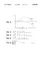
- FIG. 1shows a block diagram of a magnetic-article proximity sensor of this invention.
- FIGS. 2, 3, 4, 5 and 6relate to the proximity detector of FIG. 1 and are all drawn to the same time scale.
- FIG. 3shows a waveform of the binary signal Vbig in the AGC circuit.
- FIG. 4shows the waveform of the binary signal Vclk in the AGC circuit.
- FIG. 5shows the waveform of the binary signal V R in the AGC circuit.
- FIG. 6shows the count in counter 118 which sets the gain of digitally controllable amplifier 110 for successive intervals during automatic gain control.
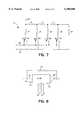
- FIG. 7shows a circuit diagram of an R/2R digital-to-analog converter (DAC).
- FIG. 8shows a block diagram 112 of the DAC of FIG. 7 connected as a digitally controllable resistor, such as may be employed as the G-DAC 112 in FIG. 1.
- FIG. 9shows a circuit diagram of the Gm-amplifier 176 employed in the proximity detector of FIG. 1.
- FIG. 10shows curves AA (dashed) and BB (solid) representing the switchable comparator hysteresis loops corresponding respectively to the two switchable thresholds of the comparator of slope detector 50 in FIG. 1.
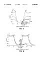
- FIG. 11shows superimposed three waveforms of V H , in the proximity detector of FIG. 1 corresponding respectively to three air gap spacings.
- FIG. 12shows superimposed three waveforms of V H corresponding to three air gap spacings in the proximity detector of FIG. 1 with the AGC circuit enabled.
- FIG. 13shows the waveforms of Vcap (heavy line) and corresponding Vsig (thin line where not obscured) with overshoots that are greater than the hysteresis of the signal-detector comparators in FIG. 1.
- FIG. 14shows the waveform of the output voltage Vout under the conditions represented in FIG. 13.
- FIG. 15shows the waveforms of Vcap in the proximity detector of FIG. 1 wherein the hysteresis of the comparator is greater than the overshoots in Vsig.
- FIG. 16shows a waveform of the output voltage Vout under the conditions indicated in FIG. 15.
- FIGS. 17, 18, 19, 20 and 21are waveforms in the proximity detector of FIG. 1 that represent the condition in which Vsig at start-up is large enough to actuate AGC. These five waveforms are drawn to the same time scale.
- FIG. 17shows the first few excursions after start-up in the waveform of Vsig.
- FIG. 18shows the waveform at junction 188 of the signal, V dif .
- FIG. 19shows the waveform of voltage, Vcap, across the capacitor 177.
- FIG. 20shows the waveform of the signal voltage, V.sub..increment.th, for enabling switching from the large to the small signal-detector threshold and for enabling AGC.
- FIG. 21shows the waveform of the proximity detector output voltage, Vout.
- comparator 190 and resistors 192, 193, 214 and 215form a Schmitt circuit with only one single fixed hysteresis.
- the waveforms shown in FIGS. 2 through 6pertain to this initial discussion.
- the output of the Hall transducer 10is connected to the fixed-gain Hall voltage amplifier 65 which is in turn connected to the input of a digitally controllable gain stage 110 composed of a digital-to-analog converter G-DAC 112, two resistors 113 and 114, and an operational amplifier 69.
- the Hall-voltage amplifier 65, and the controllable amplifier 110 combined with M-counter 118,comprises an AGC circuit 25 that generates the signal Vsig.
- the counter 118is a down counter which is reset to its maximum count by logic block 119 only at the time when the proximity detector is started, namely at proximity-detector start-up when +Vreg is turned on. Counter 118 does not wrap after the unlikely event that the count has reached zero.
- the positive going transitions in clock signal Vclkare counted by M-counter 118 when enabled via AND gate 212 by the signal V.sub..increment.th.
- G-DAC 112is connected internally as a digitally programmable resistor having a maximum resistance when the input count to the DAC is zero.
- This G-DAC resistorin parallel with resistor 113 sets the total input resistance R in to the operational amplifier 69 at its lowest value when the counter 118 is at maximum count.
- the gain of this digitally controlled amplifieris R 114 /R in , and at maximum count when R in is at its minimum value the amplifier gain is the greatest.
- the amplified Hall voltage Vsigis applied to one input of comparator 130 and a DC reference voltage V HI is connected to the other input of comparator 130.
- V big(FIG. 3) at the output of comparator 130 goes high at time t 1 .
- VclkFIG. 4
- the output Vclk(FIG. 4) of the latch of cross-coupled NOR gates 131 and 133 is caused to go high, V clk passes through NOR gate 147 and AND gate 212 and the count in counter 118 decreases by one.
- AGC actionhas been initiated.
- the resistance of G-DAC 112goes up by an incremental amount
- the gain of amplifier 110decreases by a corresponding incremental amount and there is an incremental drop in the voltage Vsig that occurs at time t 1 .
- Vclkpasses through the delay circuit 134 (e.g. a 5 ⁇ sec delay), and at 5 ⁇ sec after t 1 the reset input signal V R (FIG. 5) to NOR gate 133 goes high to reset the NOR gates latch.
- Vsigis amplified less after t 1 .
- Vbiggoes high, but at the output of NOR gate 133 the high, V R (FIG. 5), holds the latch reset for the time of delay 134 until t 2 .
- V Rthe high in Vbig can set the latch again and drop the gain of the amplifier 110 a second time. This sequence of events is repeated until at time t 4 , Vsig remains below the reference voltage V HI .
- the dashed curve V noAGC in FIG. 2shows the waveform of the excursion of Vsig that would have occurred if the gain of the amplifier 110 had remained constant, i.e. there had been no automatic gain control.
- nis the gain setting count in counter 118 prior to time t 1 . Successive counts (n-1) through (n-4) decrease leading to successive decreases in amplifier gain. If the following positive peaks in transducer signal V H remain the same, the gain setting count in counter 118 will not drop but will be held. It can therefore be appreciated that AGC action will have been substantially terminated during appearance of the very first positive excursion in Vsig after energizing the proximity detector. Any following excursions in Vsig that exceed V HI can trigger more gain reduction (up until the first 64 positive excursions have occurred).
- the AGC circuitadditionally includes a negative peak comparator 140, a new fixed DC reference voltage generator V LO , another latch of cross-coupled NOR gates 141 and 143, and another delay circuit 144.
- the added OR gate 147has inputs connected to the outputs of the two cross-coupled latches and produces a composite clock signal Vclk that is applied to the input of the down counter 118.
- V HIthe gain is adjusted downward. If a subsequent negative going excursion in Vsig is still less than V LO , the gain is further downward adjusted so that the peaks of both polarities in Vsig are within the range of from V LO to V HI , and asymmetrical waveforms in V H of any extreme are quickly brought within the dynamic operating range of the amplifier by the AGC circuit of FIG. 1.
- the G-DAC 112 in FIG. 1serves essentially as a digitally-controllable resistor, and may employ the well known R/2R type DAC connected as shown in FIG. 7.
- Each of the three resistors shown at the top of FIG. 7has a resistance R, while the other four resistors have a resistance of 2R.
- the corresponding external leads of DAC 112are shown both in the full circuit of FIG. 7 and the block diagrammed DAC 112 in FIG. 8.
- a lead 161is grounded while leads 162 and 164 are connected respectively to the output of the first Hall-voltage amplifier 65 and to the input of the operational amplifier 69.
- the four switches 151, 152, 153 and 154represent electronic switches to which are connected the four digit count signal D0, D 1 , D 2 and D 3 from the gain counter (e.g. 118). Switches 151, 152, 153 and 154 are shown in the positions wherein all four digits in the input count signal are high and the resistance between leads 162 and 164 is at a minimum value.
- the paralleling resistor 113is not essential. Resistor 113 drops the minimum resistance of the paralleled combination at the input of the operational amplifier but more importantly reduces the maximum operational amplifier input resistance, i.e. maximum R in .
- the G-DACsWhen grounded the G-DACs become digitally-controllable voltage dividers, and the effective resistance between conductors 162 and 164 becomes essentially a linear function of the digital count to the G-DAC 112 when R is large enough that the resistance between terminals 161 and 162 is much larger than the output impedance of the Hall-voltage amplifier 65.
- amplifier gainis a linear function of the count.
- a peak-referenced-threshold signal detector circuit 50follows the automatic gain control circuit 25.
- the peak referenced threshold detector 50uses the same principle of applying the difference voltage between Vsig and a held peak voltage in Vsig to the input of a threshold comparator such as a Schmitt trigger circuit.
- Signal detector 50however is quite different, and somewhat simpler, e.g. employing only one instead of two Schmitt trigger circuits.
- Peak-referenced-threshold signal detector circuit 50employs a transconductance amplifier (gmAmp) 176 that generates at its output a current having an amplitude that is commensurate with its differential input voltage.
- a capacitor 177is alternately charged and discharged by the output current from amplifier 176. For example when Vsig is decreasing, the capacitor 177 will be charging and the capacitor voltage Vcap will be increasing.
- the capacitor voltage Vcapis fed back via buffer amplifier 178 and through feedback resistor 179 (of resistance R) to the negative input of gM-amplifier 176. Junction 182 is connected via resistor 180 (of resistance R) to the negative input of gmAmp 176. This feedback circuit insures that when the capacitor 177 is either charging or discharging, the capacitor voltage Vcap will track Vsig with reversed polarity.
- the gmAmp 176is, as will be seen, energized from only a positive DC supply voltage, +Vreg, and cannot draw down Vcap below ground, i.e. zero volts. However, the positive input of gmAmp 176 is connected via resistor 183 to a positive source 184 of DC voltage Vm, about midway between ground and +Vreg. This results in Vcap being centered at roughly Vreg/2and Vsig is also so centered within the dynamic range of AGC amplifier 110.
- the average voltage level, Va, at node 188is the reference level in the signal V dif (FIG. 18) and is the center reference level in the hysteresis characteristic of the Schmitt comparator (FIG. 10). Va is set by design to equal Vm.
- the output signal voltage, V t&h , from buffer amplifier 178is tied to circuit junction 185 at which the voltage Vcap appears, so that V t&h equals Vcap.
- Series connected resistors 186 and 187serve as a summing circuit and are connected between junctions 185 and 182 to provide a signal V dif . Since Vsig is applied to the negative input of gmAmp, Vcap goes lower when Vsig grows more positive. V dif is thus the difference between Vsig at junction 182 and Vcap which is equal to V t&h at node 185.
- V dif at the junction 188 between resistors 186 and 187is connected to the negative input of a Schmitt trigger circuit that includes the zero-crossing comparator 190 and the hysteresis determining resistors 192, 214 and 215.
- the positive input of the comparator 190is connected via resistors 192 and 193 to the voltage source 184.
- the circuit of the gmAmp 176has a differential input stage of transistors 195 and 196 that ration the current I A between the current-source diodes 198 and 199 respectively.
- Vsigis applied at junction 182 to the base of transistor 195 via resistor 180.
- the current I+ in transistor 201for charging capacitor 177, mirrors the current through diode 199.
- the current I- in transistor 203for discharging capacitor 177, mirrors the current through diode 204 and via transistor 205 mirrors the current through diode 198.
- Vout from invertor 191is seen to be the binary output signal of the entire proximity detector that has transitions at times t x , i.e. at times t 1 , t 2 , etc., as in FIG. 21.
- This binary signal, Voutis seen in FIG. 9 to be applied directly to the base of transistor 207, and applied via invertor 206 to transistor 209.
- Transistors 207 and 209are alternately turned on by the signal Vout, applied to the gmAmp 176 so as to alternately hold off (and on) transistors 201 and 203 respectively. Therefore currents I+ and I- are never on at the same time.
- the capacitor voltage Vcapis briefly discharged and set to near zero voltage by the start logic 211, and capacitor 177 can then only be charged by a current I+.
- Vcapincreases. Vcap increases until Vsig reaches the negative peak and thereafter holds the corresponding Vcap voltage at that level until, at the time t 1 , when Vsig has increased to a value that is greater than the held Vcap voltage by an amount equal to the hysteresis V th of the Schmitt-trigger comparator 190.
- V difat junction 188 FIG. 1, is the difference voltage between signals appearing at junctions 182 and 185, and the positive going pulse in V dif at t 1 , (FIG. 18) is applied to the negative input of the comparator 190 that results in a positive transition in the binary signal Vout (FIG. 21).
- Voutgoes high when the signal V dif falls below Va by the Schmitt threshold voltage, V th at time t 1 .
- I-is set and held at zero from start-up to time t 1 .
- Voutgoes from a low to a high binary level, a positive transition, and then I- is turned on and discharges capacitor 177 to drop Vcap to the current t 1 value of Vsig.
- Vcapis then caused to track Vsig with inverse polarity until the positive peak in Vsig has occurred.
- Vcapsubsequently holds the corresponding lowest value (negative peak value) until at time t 2 , Vsig has at time t 2 decreased to a value below the held Vcap voltage by an amount equal to the (still assumed fixed) hysteresis V th of the Schmitt-trigger comparator 190, causing the Schmitt output from comparator 190 to go high and Vout (FIG. 21) to go low.
- VsigAssume that the first positive excursion in Vsig exceeds V HI . Before time t 2 , Vsig reaches V HI and initiates AGC action at time t.sub..increment.th, which then truncates the positive peak in Vsig while reducing the gain so that any following positive peak in Vsig will have an amplitude of V HI , obviating further AGC action at such positive peaks.
- Vsig first reaches V HIV big goes high at the input of AND gate 224.
- FIG. 11shows waveforms V Hs , V Hm and V Hl respectively for a small, a medium- and a large-dimension air gap using a proximity detector without an AGC feature and without a dual-threshold-mode signal detector. But the waveforms of FIG. 11 may also truly represent Vsig in FIG. 1 with the AGC feature disabled.
- these waveformsare positive and include two spikes U and W corresponding respectively to the leading and retreating edge of the gear tooth.
- the negative-going portions of the waveformscorrespond to the valleys between the gear teeth and have no such spikes.
- the slopes of V Hdecrease at larger air gaps.
- the three signals V Hhave been amplified by an AGC amplifier that renders their amplitudes equal.
- the three amplified signalsare labeled V sigS , V sigM and V sigL , and correspond respectively to the same small, medium and large air gaps.
- V HysBthe degrees of gear rotation between t 0 and the times of detection t 4 , t 5 and t 6 are seen to be larger and more spread out as a function of air gap than for a small detection threshold V thA , with or without AGC.
- overshootsThe shape of the positive peak in Vsig, when as here the positive peak corresponds to the top of a gear tooth, tends to include overshoot or spike portions U and W, especially when the air gap is small. These overshoot or spike portions are henceforth referred to as "overshoots”.
- the second overshoot Wis then initially treated by the detector as a second positive excursion in Vsig indicating falsely that two gear teeth had passed when there was actually only one. That situation may be resolved by increasing the magnitude of the hysteresis beyond that of the overshoots, as is illustrated in FIGS. 15 and 16.
- the relative amplitudes of overshoots compared to that of the entire transducer signal V Hare very high for small air gap dimensions and approaches zero for large air gaps.
- the AGC featurewill, quickly at starting, produce a signal Vsig that is of a desired amplitude, but it may include large overshoots or none at all.
- this problemis solved by the dual hysteresis feature of this invention. How the dual hysteresis feature operates in the proximity detector of FIG. 1 is described later herein.
- a circuitfor switching between the dual comparator thresholds. This is done by switching between a small hysteresis and a large hysteresis of the signal-detector comparator (comprised of comparator 190, resistors 214 and 215, and the bi-directional switch 217).
- Vcapcauses Vcap to hold the corresponding level until signal voltage Vsig turns downward and V dif becomes negative enough at time t 2 to trip the Schmitt trigger circuit that now has a small threshold V thA .
- start-upoccurred at a moment when Vsig was going negative and subsequently exceeded V HI , and in that situation the output signal V.sub..increment.th waits to enable the AGC circuit 25 and waits to enable a change in hysteresis of the Schmitt trigger circuit until the first positive excursion in Vsig when Vbig is simultaneously high.
- VsigIf no positive excursions in Vsig exceed V HI , then V big never goes high and there will be no AGC action. In this case, automatic threshold switching will still occur.
- Start logicalso initially sets the threshold of the Schmitt circuit to the large threshold V thB , and resets latches 213 and 222.
- the Schmitt thresholdis still large, V thB )
- counter 220produces a high output to OR gate 218 which sets latch 213 and produces transition to a high binary level in V.sub..increment.th that opens switch 217.
- the signal V difhas small positive and negative excursions equal to the small hysteresis threshold V thA .
- the large threshold V thBis always set at start-up.
- Vsigexceeds V HI
- the Schmitt comparatoris switched to the small threshold, V thA .
- the small Schmitt threshold, V thAis switched in when the output of counter 220 goes high at time t 4 , or more generally before the first five excursions in Vsig have transpired. Therefore, the Schmitt threshold is under all conditions switched to the small value V thA before the first five excursions in Vsig have transpired.
- the high initial AGC amplifier gainassures that when the passing articles are passing at a substantial distance with respect to the transducer the resulting small signal V H will still provide a signal Vsig that is large enough to be detected.
- the large initial threshold V thBassures that when the passing articles are passing at a very small distance with respect to the transducer the resulting large signal V H with large overshoots will not produce false detection indications in Vout.
- the low threshold V thAwhich always is used after at most the four initial excursions in Vsig, guarantees high detection accuracy for all of the rest of the detecting thereafter.
- the digitally-gain-controllable amplifier based upon use of G-DAC 112may alternatively be based upon an operational amplifier with an input and a feedback resistor, wherein there is substituted for the input resistor a group of parallel connected branch circuits, each containing a resistor and a binary-signal controllable switch for digitally controlling the resistance of the input resistor.
- the purpose of effecting automatic gain adjustment for only a few (e.g. 2) of the first excursions in Vsigis to avoid subsequent quick shifts in the actual distance of approaching articles at which a corresponding transition in Vout occurs.
- the timing of engine firingtends to cause small but annoying jumps in engine power delivery.
- continuous gain adjustmentis another option, e.g. by removing the AND gate 212 and permanently connecting the output of OR gate 147 directly to the input of M-counter 118.
- the signal V biggoes high only when a positive excursion in Vsig exceeds V HI .
- the signal V bigcould have been caused to go high when a negative excursion in Vsig exceeds V LO , which would then enable AGC action and enable switching to the small detector threshold V thA as described above.
Landscapes
- Engineering & Computer Science (AREA)
- Physics & Mathematics (AREA)
- General Physics & Mathematics (AREA)
- Signal Processing (AREA)
- Theoretical Computer Science (AREA)
- Technology Law (AREA)
- Electronic Switches (AREA)
Abstract
Description
Claims (6)
Priority Applications (1)
| Application Number | Priority Date | Filing Date | Title |
|---|---|---|---|
| US08/851,402US6100680A (en) | 1996-01-17 | 1997-05-05 | Detecting the passing of magnetic articles using a transducer-signal detector having a switchable dual-mode threshold |
Applications Claiming Priority (2)
| Application Number | Priority Date | Filing Date | Title |
|---|---|---|---|
| US08/587,406US5694038A (en) | 1996-01-17 | 1996-01-17 | Detector of passing magnetic articles with automatic gain control |
| US08/851,402US6100680A (en) | 1996-01-17 | 1997-05-05 | Detecting the passing of magnetic articles using a transducer-signal detector having a switchable dual-mode threshold |
Related Parent Applications (1)
| Application Number | Title | Priority Date | Filing Date |
|---|---|---|---|
| US08/587,406Continuation-In-PartUS5694038A (en) | 1996-01-17 | 1996-01-17 | Detector of passing magnetic articles with automatic gain control |
Publications (1)
| Publication Number | Publication Date |
|---|---|
| US6100680Atrue US6100680A (en) | 2000-08-08 |
Family
ID=46203110
Family Applications (1)
| Application Number | Title | Priority Date | Filing Date |
|---|---|---|---|
| US08/851,402Expired - LifetimeUS6100680A (en) | 1996-01-17 | 1997-05-05 | Detecting the passing of magnetic articles using a transducer-signal detector having a switchable dual-mode threshold |
Country Status (1)
| Country | Link |
|---|---|
| US (1) | US6100680A (en) |
Cited By (84)
| Publication number | Priority date | Publication date | Assignee | Title |
|---|---|---|---|---|
| US6446788B1 (en) | 2001-03-12 | 2002-09-10 | Owens-Brockway Glass Container Inc. | Linear conveyor speed sensor |
| US6448768B1 (en)* | 1997-02-28 | 2002-09-10 | Asahi Kasei Electronics Co., Ltd. | Magnetic sensor with a signal processing circuit |
| US6522131B1 (en)* | 1999-09-17 | 2003-02-18 | Melexis Nv | Multi-mode hall effect sensor for determining position and timing parameters of a gear wheel |
| WO2003039926A1 (en)* | 2001-11-07 | 2003-05-15 | Siemens Aktiengesellschaft | Analytical circuit for an inductive sensor |
| US20030140931A1 (en)* | 2002-01-29 | 2003-07-31 | Zeijlemaker Volkert A. | Medical implantable system for reducing magnetic resonance effects |
| US20040100150A1 (en)* | 2002-11-26 | 2004-05-27 | Stephan Bolz | Circuit arrangement for high-speed switching of inductive loads |
| US20040130379A1 (en)* | 2002-11-13 | 2004-07-08 | Stephan Bolz | Circuit arrangement for rapidly controlling in particular inductive loads |
| US20050024501A1 (en)* | 1996-05-22 | 2005-02-03 | John Ellenby | Method and apparatus for controlling the operational mode of electronic devices in response to sensed conditions |
| US20050162158A1 (en)* | 2003-11-07 | 2005-07-28 | Mauro Del Monte | Inductive proximity sensor, particularly for sensing presence of ferrous and non-ferrous materials |
| US20050194970A1 (en)* | 2004-03-08 | 2005-09-08 | Karl Scheller | Proximity detector |
| US20060009941A1 (en)* | 2004-06-21 | 2006-01-12 | Mario Motz | System for evaluating a sensor signal |
| US20070059936A1 (en)* | 2003-09-19 | 2007-03-15 | Koninklijke Philips Electronics N.V. | Electronic sensing circuit |
| US20080071168A1 (en)* | 2006-07-26 | 2008-03-20 | Karl Gauglitz | Systems and methods for sensing external magnetic fields in implantable medical devices |
| US20080143327A1 (en)* | 2006-01-17 | 2008-06-19 | Cory Voisine | Methods and apparatus for magnetic article detection |
| US20080164871A1 (en)* | 2004-04-08 | 2008-07-10 | Bailey James M | Methods and apparatus for vibration detection |
| US20090067616A1 (en)* | 2007-09-07 | 2009-03-12 | Kerby William Suhre | CAN echo cancellation level shifter |
| US20090121707A1 (en)* | 2007-06-04 | 2009-05-14 | Melexis Nv | Magnetic field orientation sensor |
| US20090201017A1 (en)* | 2007-12-07 | 2009-08-13 | Melexis Nv | Hall sensor array |
| US20100066359A1 (en)* | 2007-06-11 | 2010-03-18 | Alps Electric Co., Ltd. | Magnetic detection device and electrical product |
| CN101806872A (en)* | 2009-02-17 | 2010-08-18 | 罗姆股份有限公司 | Magnetic Sensor and possess the electronic equipment of this Magnetic Sensor |
| US20100231202A1 (en)* | 2009-03-10 | 2010-09-16 | Scheller P Karl | Magnetic field detector having a variable threshold |
| US20100264909A1 (en)* | 2009-04-17 | 2010-10-21 | Scheller P Karl | Circuits and Methods for Providing a Magnetic Field Sensor with an Adaptable Threshold |
| US20110050285A1 (en)* | 2009-08-27 | 2011-03-03 | Qualcomm Incorporated | High linear fast peak detector |
| US20110048102A1 (en)* | 2009-08-27 | 2011-03-03 | Devon Fernandez | Circuits and Methods for Calibration of a Motion Detector |
| US8729890B2 (en) | 2011-04-12 | 2014-05-20 | Allegro Microsystems, Llc | Magnetic angle and rotation speed sensor with continuous and discontinuous modes of operation based on rotation speed of a target object |
| US8749005B1 (en) | 2012-12-21 | 2014-06-10 | Allegro Microsystems, Llc | Magnetic field sensor and method of fabricating a magnetic field sensor having a plurality of vertical hall elements arranged in at least a portion of a polygonal shape |
| US8786279B2 (en) | 2011-02-25 | 2014-07-22 | Allegro Microsystems, Llc | Circuit and method for processing signals generated by a plurality of sensors |
| US8793085B2 (en) | 2011-08-19 | 2014-07-29 | Allegro Microsystems, Llc | Circuits and methods for automatically adjusting a magnetic field sensor in accordance with a speed of rotation sensed by the magnetic field sensor |
| US8860410B2 (en) | 2011-05-23 | 2014-10-14 | Allegro Microsystems, Llc | Circuits and methods for processing a signal generated by a plurality of measuring devices |
| US8890518B2 (en) | 2011-06-08 | 2014-11-18 | Allegro Microsystems, Llc | Arrangements for self-testing a circular vertical hall (CVH) sensing element and/or for self-testing a magnetic field sensor that uses a circular vertical hall (CVH) sensing element |
| US8922206B2 (en) | 2011-09-07 | 2014-12-30 | Allegro Microsystems, Llc | Magnetic field sensing element combining a circular vertical hall magnetic field sensing element with a planar hall element |
| US9046383B2 (en) | 2012-01-09 | 2015-06-02 | Allegro Microsystems, Llc | Systems and methods that use magnetic field sensors to identify positions of a gear shift lever |
| US9062990B2 (en) | 2011-02-25 | 2015-06-23 | Allegro Microsystems, Llc | Circular vertical hall magnetic field sensing element and method with a plurality of continuous output signals |
| US9099638B2 (en) | 2013-03-15 | 2015-08-04 | Allegro Microsystems, Llc | Vertical hall effect element with structures to improve sensitivity |
| US9182456B2 (en) | 2012-03-06 | 2015-11-10 | Allegro Microsystems, Llc | Magnetic field sensor for sensing rotation of an object |
| US9285438B2 (en) | 2011-09-28 | 2016-03-15 | Allegro Microsystems, Llc | Circuits and methods for processing signals generated by a plurality of magnetic field sensing elements |
| US9312473B2 (en) | 2013-09-30 | 2016-04-12 | Allegro Microsystems, Llc | Vertical hall effect sensor |
| US9329057B2 (en) | 2012-05-31 | 2016-05-03 | Allegro Microsystems, Llc | Gear tooth sensor with peak and threshold detectors |
| US9377285B2 (en) | 2013-02-13 | 2016-06-28 | Allegro Microsystems, Llc | Magnetic field sensor and related techniques that provide varying current spinning phase sequences of a magnetic field sensing element |
| US9389060B2 (en) | 2013-02-13 | 2016-07-12 | Allegro Microsystems, Llc | Magnetic field sensor and related techniques that provide an angle error correction module |
| US9400164B2 (en) | 2013-07-22 | 2016-07-26 | Allegro Microsystems, Llc | Magnetic field sensor and related techniques that provide an angle correction module |
| US9417295B2 (en) | 2012-12-21 | 2016-08-16 | Allegro Microsystems, Llc | Circuits and methods for processing signals generated by a circular vertical hall (CVH) sensing element in the presence of a multi-pole magnet |
| US9448288B2 (en) | 2014-05-20 | 2016-09-20 | Allegro Microsystems, Llc | Magnetic field sensor with improved accuracy resulting from a digital potentiometer |
| US9520871B2 (en) | 2012-01-05 | 2016-12-13 | Allegro Microsystems, Llc | Methods and apparatus for supply voltage transient protection for maintaining a state of a sensor output signal |
| US9523742B2 (en) | 2015-04-27 | 2016-12-20 | Allegro Microsystems, Llc | Circuits and methods for modulating current in circuits comprising sensing elements |
| US9547048B2 (en) | 2014-01-14 | 2017-01-17 | Allegro Micosystems, LLC | Circuit and method for reducing an offset component of a plurality of vertical hall elements arranged in a circle |
| US9548443B2 (en) | 2013-01-29 | 2017-01-17 | Allegro Microsystems, Llc | Vertical Hall Effect element with improved sensitivity |
| US9574867B2 (en) | 2013-12-23 | 2017-02-21 | Allegro Microsystems, Llc | Magnetic field sensor and related techniques that inject an error correction signal into a signal channel to result in reduced error |
| US9606190B2 (en) | 2012-12-21 | 2017-03-28 | Allegro Microsystems, Llc | Magnetic field sensor arrangements and associated methods |
| US9638766B2 (en) | 2014-11-24 | 2017-05-02 | Allegro Microsystems, Llc | Magnetic field sensor with improved accuracy resulting from a variable potentiometer and a gain circuit |
| US9684042B2 (en) | 2015-02-27 | 2017-06-20 | Allegro Microsystems, Llc | Magnetic field sensor with improved accuracy and method of obtaining improved accuracy with a magnetic field sensor |
| US9739847B1 (en) | 2016-02-01 | 2017-08-22 | Allegro Microsystems, Llc | Circular vertical hall (CVH) sensing element with signal processing |
| US9739848B1 (en) | 2016-02-01 | 2017-08-22 | Allegro Microsystems, Llc | Circular vertical hall (CVH) sensing element with sliding integration |
| US9753097B2 (en) | 2014-05-05 | 2017-09-05 | Allegro Microsystems, Llc | Magnetic field sensors and associated methods with reduced offset and improved accuracy |
| US9778326B2 (en) | 2014-03-11 | 2017-10-03 | Allegro Microsystems, Llc | Circuits and methods for limiting a smallest separation of thresholds in a magnetic field sensor |
| US9823092B2 (en) | 2014-10-31 | 2017-11-21 | Allegro Microsystems, Llc | Magnetic field sensor providing a movement detector |
| US9970996B2 (en) | 2015-01-20 | 2018-05-15 | Allegro Microsystems, Llc | Methods and apparatus for generating a threshold signal in a magnetic field sensor |
| US10120042B2 (en) | 2013-12-23 | 2018-11-06 | Allegro Microsystems, Llc | Magnetic field sensor and related techniques that inject a synthesized error correction signal into a signal channel to result in reduced error |
| US20190015731A1 (en)* | 2014-11-05 | 2019-01-17 | Future Motion, Inc. | Rider detection system |
| US10215550B2 (en) | 2012-05-01 | 2019-02-26 | Allegro Microsystems, Llc | Methods and apparatus for magnetic sensors having highly uniform magnetic fields |
| US10308306B2 (en) | 2016-06-02 | 2019-06-04 | Future Motion, Inc. | Vehicle rider detection using strain gauges |
| US10385964B2 (en) | 2016-06-08 | 2019-08-20 | Allegro Microsystems, Llc | Enhanced neutral gear sensor |
| US10481220B2 (en) | 2016-02-01 | 2019-11-19 | Allegro Microsystems, Llc | Circular vertical hall (CVH) sensing element with signal processing and arctangent function |
| US10495701B2 (en) | 2017-03-02 | 2019-12-03 | Allegro Microsystems, Llc | Circular vertical hall (CVH) sensing element with DC offset removal |
| US10585147B2 (en) | 2016-06-14 | 2020-03-10 | Allegro Microsystems, Llc | Magnetic field sensor having error correction |
| US10739164B2 (en) | 2017-01-27 | 2020-08-11 | Allegro Microsystems, Llc | Circuit for detecting motion of an object |
| US10823586B2 (en) | 2018-12-26 | 2020-11-03 | Allegro Microsystems, Llc | Magnetic field sensor having unequally spaced magnetic field sensing elements |
| US10921341B2 (en) | 2019-05-09 | 2021-02-16 | Allegro Microsystems, Llc | Methods and apparatus for generating a uniform response in a magnetic field sensor |
| US11029176B2 (en) | 2019-05-07 | 2021-06-08 | Allegro Microsystems, Llc | System and method for vibration detection with no loss of position information using a magnetic field sensor |
| US11125837B2 (en) | 2020-01-14 | 2021-09-21 | Allegro Microsystems, Llc | Magnetic field sensor offset and gain adjustment |
| US11125590B2 (en) | 2019-05-07 | 2021-09-21 | Allegro Microsystems, Llc | System and method for vibration detection with direction change response immunity using a magnetic field sensor |
| US11163022B2 (en) | 2015-06-12 | 2021-11-02 | Allegro Microsystems, Llc | Magnetic field sensor for angle detection with a phase-locked loop |
| US11237020B2 (en) | 2019-11-14 | 2022-02-01 | Allegro Microsystems, Llc | Magnetic field sensor having two rows of magnetic field sensing elements for measuring an angle of rotation of a magnet |
| US11273364B1 (en) | 2021-06-30 | 2022-03-15 | Future Motion, Inc. | Self-stabilizing skateboard |
| US11280637B2 (en) | 2019-11-14 | 2022-03-22 | Allegro Microsystems, Llc | High performance magnetic angle sensor |
| US11294000B1 (en) | 2020-10-01 | 2022-04-05 | Allegro Microsystems, Llc | Magnetic field sensor with an adjustable threshold for stray field immunity |
| US11299059B1 (en) | 2021-10-20 | 2022-04-12 | Future Motion, Inc. | Self-stabilizing skateboard |
| US11473935B1 (en) | 2021-04-16 | 2022-10-18 | Allegro Microsystems, Llc | System and related techniques that provide an angle sensor for sensing an angle of rotation of a ferromagnetic screw |
| CN115664363A (en)* | 2022-11-07 | 2023-01-31 | 武汉市聚芯微电子有限责任公司 | Gain control device and method |
| US11733025B2 (en) | 2021-10-14 | 2023-08-22 | Allegro Microsystems, Llc | Dynamic offset and amplitude tracker |
| US11802922B2 (en) | 2021-01-13 | 2023-10-31 | Allegro Microsystems, Llc | Circuit for reducing an offset component of a plurality of vertical hall elements arranged in one or more circles |
| US11890528B1 (en) | 2022-11-17 | 2024-02-06 | Future Motion, Inc. | Concave side rails for one-wheeled vehicles |
| US12174275B2 (en) | 2021-01-04 | 2024-12-24 | Allegro Microsystems, Llc | Magnetic field closed loop sensors with offset reduction |
| US12187373B1 (en) | 2024-02-29 | 2025-01-07 | Future Motion, Inc. | Skateboard footpads having foot engagement structures and traction inserts |
Citations (7)
| Publication number | Priority date | Publication date | Assignee | Title |
|---|---|---|---|---|
| US4908527A (en)* | 1988-09-08 | 1990-03-13 | Xolox Corporation | Hall-type transducing device |
| US5442283A (en)* | 1993-09-03 | 1995-08-15 | Allegro Microsystems, Inc. | Hall-voltage slope-activated sensor |
| US5459398A (en)* | 1993-12-17 | 1995-10-17 | Delco Electronics Corporation | Adaptive threshold circuit |
| US5477142A (en)* | 1994-02-22 | 1995-12-19 | Delco Electronics Corporation | Variable reluctance sensor interface using a differential input and digital adaptive control |
| US5487595A (en)* | 1994-02-28 | 1996-01-30 | Delco Electronics Corporation | Dual hysteresis method of generating square waves from automotive wheel speed signals |
| US5493219A (en)* | 1993-04-15 | 1996-02-20 | Nippondenso Co., Ltd. | MRE sensor signal detector |
| US5497084A (en)* | 1995-03-03 | 1996-03-05 | Honeywell Inc. | Geartooth sensor with means for selecting a threshold magnitude as a function of the average and minimum values of a signal of magnetic field strength |
- 1997
- 1997-05-05USUS08/851,402patent/US6100680A/ennot_activeExpired - Lifetime
Patent Citations (7)
| Publication number | Priority date | Publication date | Assignee | Title |
|---|---|---|---|---|
| US4908527A (en)* | 1988-09-08 | 1990-03-13 | Xolox Corporation | Hall-type transducing device |
| US5493219A (en)* | 1993-04-15 | 1996-02-20 | Nippondenso Co., Ltd. | MRE sensor signal detector |
| US5442283A (en)* | 1993-09-03 | 1995-08-15 | Allegro Microsystems, Inc. | Hall-voltage slope-activated sensor |
| US5459398A (en)* | 1993-12-17 | 1995-10-17 | Delco Electronics Corporation | Adaptive threshold circuit |
| US5477142A (en)* | 1994-02-22 | 1995-12-19 | Delco Electronics Corporation | Variable reluctance sensor interface using a differential input and digital adaptive control |
| US5487595A (en)* | 1994-02-28 | 1996-01-30 | Delco Electronics Corporation | Dual hysteresis method of generating square waves from automotive wheel speed signals |
| US5497084A (en)* | 1995-03-03 | 1996-03-05 | Honeywell Inc. | Geartooth sensor with means for selecting a threshold magnitude as a function of the average and minimum values of a signal of magnetic field strength |
Cited By (132)
| Publication number | Priority date | Publication date | Assignee | Title |
|---|---|---|---|---|
| US20050024501A1 (en)* | 1996-05-22 | 2005-02-03 | John Ellenby | Method and apparatus for controlling the operational mode of electronic devices in response to sensed conditions |
| US9009505B2 (en) | 1996-05-22 | 2015-04-14 | Qualcomm Incorporated | Method and apparatus for controlling the operational mode of electronic devices in response to sensed conditions |
| US7696905B2 (en) | 1996-05-22 | 2010-04-13 | Qualcomm Incorporated | Method and apparatus for controlling the operational mode of electronic devices in response to sensed conditions |
| US6448768B1 (en)* | 1997-02-28 | 2002-09-10 | Asahi Kasei Electronics Co., Ltd. | Magnetic sensor with a signal processing circuit |
| US6522131B1 (en)* | 1999-09-17 | 2003-02-18 | Melexis Nv | Multi-mode hall effect sensor for determining position and timing parameters of a gear wheel |
| US6446788B1 (en) | 2001-03-12 | 2002-09-10 | Owens-Brockway Glass Container Inc. | Linear conveyor speed sensor |
| WO2003039926A1 (en)* | 2001-11-07 | 2003-05-15 | Siemens Aktiengesellschaft | Analytical circuit for an inductive sensor |
| US20040196026A1 (en)* | 2001-11-07 | 2004-10-07 | Stephan Bolz | Analytical circuit for an inductive sensor |
| US7098652B2 (en) | 2001-11-07 | 2006-08-29 | Siemens Aktiengesellschaft | Analytical circuit for an inductive sensor |
| US20030140931A1 (en)* | 2002-01-29 | 2003-07-31 | Zeijlemaker Volkert A. | Medical implantable system for reducing magnetic resonance effects |
| US7050855B2 (en)* | 2002-01-29 | 2006-05-23 | Medtronic, Inc. | Medical implantable system for reducing magnetic resonance effects |
| US20040130379A1 (en)* | 2002-11-13 | 2004-07-08 | Stephan Bolz | Circuit arrangement for rapidly controlling in particular inductive loads |
| US7019579B2 (en) | 2002-11-13 | 2006-03-28 | Siemens Aktiengesellschaft | Circuit arrangement for rapidly controlling in particular inductive loads |
| US20040100150A1 (en)* | 2002-11-26 | 2004-05-27 | Stephan Bolz | Circuit arrangement for high-speed switching of inductive loads |
| US20070059936A1 (en)* | 2003-09-19 | 2007-03-15 | Koninklijke Philips Electronics N.V. | Electronic sensing circuit |
| US7301330B2 (en)* | 2003-09-19 | 2007-11-27 | Nxp B.V. | Electronic sensing circuit that compensates for reference voltage drift |
| US20050162158A1 (en)* | 2003-11-07 | 2005-07-28 | Mauro Del Monte | Inductive proximity sensor, particularly for sensing presence of ferrous and non-ferrous materials |
| US7368904B2 (en) | 2004-03-08 | 2008-05-06 | Allegro Microsystems, Inc. | Proximity detector |
| US7199579B2 (en)* | 2004-03-08 | 2007-04-03 | Allegro Microsystems, Inc. | Proximity detector |
| US20050194970A1 (en)* | 2004-03-08 | 2005-09-08 | Karl Scheller | Proximity detector |
| US20070132450A1 (en)* | 2004-03-08 | 2007-06-14 | Karl Scheller | Proximity detector |
| US7622914B2 (en) | 2004-04-08 | 2009-11-24 | Allegro Microsystems, Inc. | Methods and apparatus for vibration detection |
| US20090153137A1 (en)* | 2004-04-08 | 2009-06-18 | Bailey James M | Methods and Apparatus for Vibration Detection |
| US20080164871A1 (en)* | 2004-04-08 | 2008-07-10 | Bailey James M | Methods and apparatus for vibration detection |
| US20090102469A1 (en)* | 2004-04-08 | 2009-04-23 | Bailey James M | Methods and Apparatus for Vibration Detection |
| US7772838B2 (en) | 2004-04-08 | 2010-08-10 | Allegro Microsystems, Inc. | Methods and apparatus for vibration detection |
| US7592801B2 (en) | 2004-04-08 | 2009-09-22 | Allegro Microsystems, Inc. | Methods and apparatus for vibration detection |
| US7231325B2 (en) | 2004-06-21 | 2007-06-12 | Infineon Technologies Ag | System for evaluating a sensor signal |
| US20060009941A1 (en)* | 2004-06-21 | 2006-01-12 | Mario Motz | System for evaluating a sensor signal |
| EP2339300A3 (en)* | 2006-01-17 | 2012-05-16 | Allegro Microsystems Inc. | Methods and apparatus for magnetic article detection |
| US7548056B2 (en) | 2006-01-17 | 2009-06-16 | Allegro Microsystems, Inc. | Methods and apparatus for magnetic article detection |
| US7619406B2 (en) | 2006-01-17 | 2009-11-17 | Allegro Microsystems, Inc. | Methods and apparatus for magnetic article detection |
| US20080143327A1 (en)* | 2006-01-17 | 2008-06-19 | Cory Voisine | Methods and apparatus for magnetic article detection |
| US20080143326A1 (en)* | 2006-01-17 | 2008-06-19 | Cory Voisine | Methods and apparatus for magnetic article detection |
| US9766307B2 (en) | 2006-07-26 | 2017-09-19 | Cardiac Pacemakers, Inc. | Systems and methods for sensing external magnetic fields in implantable medical devices |
| US20080071168A1 (en)* | 2006-07-26 | 2008-03-20 | Karl Gauglitz | Systems and methods for sensing external magnetic fields in implantable medical devices |
| US8049489B2 (en)* | 2006-07-26 | 2011-11-01 | Cardiac Pacemakers, Inc. | Systems and methods for sensing external magnetic fields in implantable medical devices |
| US8710826B2 (en) | 2006-07-26 | 2014-04-29 | Cardiac Pacemakers, Inc. | Systems and methods for sensing external magnetic fields in implantable medical devices |
| US10921396B2 (en) | 2006-07-26 | 2021-02-16 | Cardiac Pacemakers, Inc. | Systems and methods for sensing external magnetic fields in implantable medical devices |
| US7965076B2 (en) | 2007-06-04 | 2011-06-21 | Melexis Nv, Microelectronic Integrated Systems | Magnetic field orientation sensor |
| US20090121707A1 (en)* | 2007-06-04 | 2009-05-14 | Melexis Nv | Magnetic field orientation sensor |
| US20100066359A1 (en)* | 2007-06-11 | 2010-03-18 | Alps Electric Co., Ltd. | Magnetic detection device and electrical product |
| US7800365B2 (en)* | 2007-06-11 | 2010-09-21 | Alps Electric Co., Ltd. | Magnetic detection device and electrical product |
| EP2159587A4 (en)* | 2007-06-11 | 2017-11-15 | Alps Electric Co., Ltd. | Magnetic detection device and electric product |
| US20090067616A1 (en)* | 2007-09-07 | 2009-03-12 | Kerby William Suhre | CAN echo cancellation level shifter |
| US20090201017A1 (en)* | 2007-12-07 | 2009-08-13 | Melexis Nv | Hall sensor array |
| US8552721B2 (en) | 2007-12-07 | 2013-10-08 | Melexis Technologies Nv | Hall sensor array |
| CN101806872B (en)* | 2009-02-17 | 2014-10-01 | 罗姆股份有限公司 | Magnetic sensor and electronic device including the same |
| US8283919B2 (en)* | 2009-02-17 | 2012-10-09 | Rohm Co., Ltd. | Magnetic sensor and electronic device including the same |
| CN101806872A (en)* | 2009-02-17 | 2010-08-18 | 罗姆股份有限公司 | Magnetic Sensor and possess the electronic equipment of this Magnetic Sensor |
| US20100207621A1 (en)* | 2009-02-17 | 2010-08-19 | Rohm Co., Ltd. | Magnetic sensor and electronic device including the same |
| US8089270B2 (en) | 2009-03-10 | 2012-01-03 | Allegro Microsystems, Inc. | Magnetic field detector having a variable threshold |
| US20100231202A1 (en)* | 2009-03-10 | 2010-09-16 | Scheller P Karl | Magnetic field detector having a variable threshold |
| US20100264909A1 (en)* | 2009-04-17 | 2010-10-21 | Scheller P Karl | Circuits and Methods for Providing a Magnetic Field Sensor with an Adaptable Threshold |
| US8058864B2 (en) | 2009-04-17 | 2011-11-15 | Allegro Microsystems, Inc. | Circuits and methods for providing a magnetic field sensor with an adaptable threshold |
| US20110048102A1 (en)* | 2009-08-27 | 2011-03-03 | Devon Fernandez | Circuits and Methods for Calibration of a Motion Detector |
| US20110050285A1 (en)* | 2009-08-27 | 2011-03-03 | Qualcomm Incorporated | High linear fast peak detector |
| US8299783B2 (en) | 2009-08-27 | 2012-10-30 | Allegro Microsystems, Inc. | Circuits and methods for calibration of a motion detector |
| US8310277B2 (en)* | 2009-08-27 | 2012-11-13 | Qualcomm, Incorporated | High linear fast peak detector |
| US8786279B2 (en) | 2011-02-25 | 2014-07-22 | Allegro Microsystems, Llc | Circuit and method for processing signals generated by a plurality of sensors |
| US9182250B2 (en) | 2011-02-25 | 2015-11-10 | Allegro Microsystems, Llc | Circular vertical hall magnetic field sensing element and method with a plurality of continuous output signals |
| US9062990B2 (en) | 2011-02-25 | 2015-06-23 | Allegro Microsystems, Llc | Circular vertical hall magnetic field sensing element and method with a plurality of continuous output signals |
| US8729890B2 (en) | 2011-04-12 | 2014-05-20 | Allegro Microsystems, Llc | Magnetic angle and rotation speed sensor with continuous and discontinuous modes of operation based on rotation speed of a target object |
| US8860410B2 (en) | 2011-05-23 | 2014-10-14 | Allegro Microsystems, Llc | Circuits and methods for processing a signal generated by a plurality of measuring devices |
| US8890518B2 (en) | 2011-06-08 | 2014-11-18 | Allegro Microsystems, Llc | Arrangements for self-testing a circular vertical hall (CVH) sensing element and/or for self-testing a magnetic field sensor that uses a circular vertical hall (CVH) sensing element |
| US8793085B2 (en) | 2011-08-19 | 2014-07-29 | Allegro Microsystems, Llc | Circuits and methods for automatically adjusting a magnetic field sensor in accordance with a speed of rotation sensed by the magnetic field sensor |
| US8922206B2 (en) | 2011-09-07 | 2014-12-30 | Allegro Microsystems, Llc | Magnetic field sensing element combining a circular vertical hall magnetic field sensing element with a planar hall element |
| US9411023B2 (en) | 2011-09-07 | 2016-08-09 | Allegro Microsystems, Llc | Magnetic field sensing element combining a circular vertical hall magnetic field sensing element with a planar hall element |
| US9285438B2 (en) | 2011-09-28 | 2016-03-15 | Allegro Microsystems, Llc | Circuits and methods for processing signals generated by a plurality of magnetic field sensing elements |
| US9520871B2 (en) | 2012-01-05 | 2016-12-13 | Allegro Microsystems, Llc | Methods and apparatus for supply voltage transient protection for maintaining a state of a sensor output signal |
| US9046383B2 (en) | 2012-01-09 | 2015-06-02 | Allegro Microsystems, Llc | Systems and methods that use magnetic field sensors to identify positions of a gear shift lever |
| US9182456B2 (en) | 2012-03-06 | 2015-11-10 | Allegro Microsystems, Llc | Magnetic field sensor for sensing rotation of an object |
| US10215550B2 (en) | 2012-05-01 | 2019-02-26 | Allegro Microsystems, Llc | Methods and apparatus for magnetic sensors having highly uniform magnetic fields |
| US9329057B2 (en) | 2012-05-31 | 2016-05-03 | Allegro Microsystems, Llc | Gear tooth sensor with peak and threshold detectors |
| US8749005B1 (en) | 2012-12-21 | 2014-06-10 | Allegro Microsystems, Llc | Magnetic field sensor and method of fabricating a magnetic field sensor having a plurality of vertical hall elements arranged in at least a portion of a polygonal shape |
| US9417295B2 (en) | 2012-12-21 | 2016-08-16 | Allegro Microsystems, Llc | Circuits and methods for processing signals generated by a circular vertical hall (CVH) sensing element in the presence of a multi-pole magnet |
| US9541424B2 (en) | 2012-12-21 | 2017-01-10 | Allegro Microsystems, Llc | Circuits and methods for processing signals generated by a circular vertical hall (CVH) sensing element in the presence of a multi-pole magnet |
| US9606190B2 (en) | 2012-12-21 | 2017-03-28 | Allegro Microsystems, Llc | Magnetic field sensor arrangements and associated methods |
| US10205093B2 (en) | 2013-01-29 | 2019-02-12 | Allegro Microsystems, Llc | Vertical hall effect element with improved sensitivity |
| US9548443B2 (en) | 2013-01-29 | 2017-01-17 | Allegro Microsystems, Llc | Vertical Hall Effect element with improved sensitivity |
| US9377285B2 (en) | 2013-02-13 | 2016-06-28 | Allegro Microsystems, Llc | Magnetic field sensor and related techniques that provide varying current spinning phase sequences of a magnetic field sensing element |
| US9389060B2 (en) | 2013-02-13 | 2016-07-12 | Allegro Microsystems, Llc | Magnetic field sensor and related techniques that provide an angle error correction module |
| US9099638B2 (en) | 2013-03-15 | 2015-08-04 | Allegro Microsystems, Llc | Vertical hall effect element with structures to improve sensitivity |
| US9400164B2 (en) | 2013-07-22 | 2016-07-26 | Allegro Microsystems, Llc | Magnetic field sensor and related techniques that provide an angle correction module |
| US9312473B2 (en) | 2013-09-30 | 2016-04-12 | Allegro Microsystems, Llc | Vertical hall effect sensor |
| US9735345B2 (en) | 2013-09-30 | 2017-08-15 | Allegro Microsystems, Llc | Vertical hall effect sensor |
| US9574867B2 (en) | 2013-12-23 | 2017-02-21 | Allegro Microsystems, Llc | Magnetic field sensor and related techniques that inject an error correction signal into a signal channel to result in reduced error |
| US10120042B2 (en) | 2013-12-23 | 2018-11-06 | Allegro Microsystems, Llc | Magnetic field sensor and related techniques that inject a synthesized error correction signal into a signal channel to result in reduced error |
| US9547048B2 (en) | 2014-01-14 | 2017-01-17 | Allegro Micosystems, LLC | Circuit and method for reducing an offset component of a plurality of vertical hall elements arranged in a circle |
| US9778326B2 (en) | 2014-03-11 | 2017-10-03 | Allegro Microsystems, Llc | Circuits and methods for limiting a smallest separation of thresholds in a magnetic field sensor |
| US9753097B2 (en) | 2014-05-05 | 2017-09-05 | Allegro Microsystems, Llc | Magnetic field sensors and associated methods with reduced offset and improved accuracy |
| US9448288B2 (en) | 2014-05-20 | 2016-09-20 | Allegro Microsystems, Llc | Magnetic field sensor with improved accuracy resulting from a digital potentiometer |
| US10753768B2 (en) | 2014-10-31 | 2020-08-25 | Allegro Microsystems, Llc | Magnetic field sensor providing a movement detector |
| US10753769B2 (en) | 2014-10-31 | 2020-08-25 | Allegro Microsystems, Llc | Magnetic field sensor providing a movement detector |
| US11307054B2 (en) | 2014-10-31 | 2022-04-19 | Allegro Microsystems, Llc | Magnetic field sensor providing a movement detector |
| US9823092B2 (en) | 2014-10-31 | 2017-11-21 | Allegro Microsystems, Llc | Magnetic field sensor providing a movement detector |
| US10307660B2 (en)* | 2014-11-05 | 2019-06-04 | Future Motion, Inc. | Rider detection systems |
| US20190015731A1 (en)* | 2014-11-05 | 2019-01-17 | Future Motion, Inc. | Rider detection system |
| US9638766B2 (en) | 2014-11-24 | 2017-05-02 | Allegro Microsystems, Llc | Magnetic field sensor with improved accuracy resulting from a variable potentiometer and a gain circuit |
| US9970996B2 (en) | 2015-01-20 | 2018-05-15 | Allegro Microsystems, Llc | Methods and apparatus for generating a threshold signal in a magnetic field sensor |
| US9684042B2 (en) | 2015-02-27 | 2017-06-20 | Allegro Microsystems, Llc | Magnetic field sensor with improved accuracy and method of obtaining improved accuracy with a magnetic field sensor |
| US9523742B2 (en) | 2015-04-27 | 2016-12-20 | Allegro Microsystems, Llc | Circuits and methods for modulating current in circuits comprising sensing elements |
| US11287489B2 (en) | 2015-06-12 | 2022-03-29 | Allegro Microsystems, Llc | Magnetic field sensor for angle detection with a phase-locked loop |
| US11163022B2 (en) | 2015-06-12 | 2021-11-02 | Allegro Microsystems, Llc | Magnetic field sensor for angle detection with a phase-locked loop |
| US10481220B2 (en) | 2016-02-01 | 2019-11-19 | Allegro Microsystems, Llc | Circular vertical hall (CVH) sensing element with signal processing and arctangent function |
| US9739848B1 (en) | 2016-02-01 | 2017-08-22 | Allegro Microsystems, Llc | Circular vertical hall (CVH) sensing element with sliding integration |
| US9739847B1 (en) | 2016-02-01 | 2017-08-22 | Allegro Microsystems, Llc | Circular vertical hall (CVH) sensing element with signal processing |
| US10308306B2 (en) | 2016-06-02 | 2019-06-04 | Future Motion, Inc. | Vehicle rider detection using strain gauges |
| US10385964B2 (en) | 2016-06-08 | 2019-08-20 | Allegro Microsystems, Llc | Enhanced neutral gear sensor |
| US10585147B2 (en) | 2016-06-14 | 2020-03-10 | Allegro Microsystems, Llc | Magnetic field sensor having error correction |
| US10739164B2 (en) | 2017-01-27 | 2020-08-11 | Allegro Microsystems, Llc | Circuit for detecting motion of an object |
| US10495701B2 (en) | 2017-03-02 | 2019-12-03 | Allegro Microsystems, Llc | Circular vertical hall (CVH) sensing element with DC offset removal |
| US10823586B2 (en) | 2018-12-26 | 2020-11-03 | Allegro Microsystems, Llc | Magnetic field sensor having unequally spaced magnetic field sensing elements |
| US11029176B2 (en) | 2019-05-07 | 2021-06-08 | Allegro Microsystems, Llc | System and method for vibration detection with no loss of position information using a magnetic field sensor |
| US11125590B2 (en) | 2019-05-07 | 2021-09-21 | Allegro Microsystems, Llc | System and method for vibration detection with direction change response immunity using a magnetic field sensor |
| US10921341B2 (en) | 2019-05-09 | 2021-02-16 | Allegro Microsystems, Llc | Methods and apparatus for generating a uniform response in a magnetic field sensor |
| US11237020B2 (en) | 2019-11-14 | 2022-02-01 | Allegro Microsystems, Llc | Magnetic field sensor having two rows of magnetic field sensing elements for measuring an angle of rotation of a magnet |
| US11280637B2 (en) | 2019-11-14 | 2022-03-22 | Allegro Microsystems, Llc | High performance magnetic angle sensor |
| US11125837B2 (en) | 2020-01-14 | 2021-09-21 | Allegro Microsystems, Llc | Magnetic field sensor offset and gain adjustment |
| US11294000B1 (en) | 2020-10-01 | 2022-04-05 | Allegro Microsystems, Llc | Magnetic field sensor with an adjustable threshold for stray field immunity |
| US12174275B2 (en) | 2021-01-04 | 2024-12-24 | Allegro Microsystems, Llc | Magnetic field closed loop sensors with offset reduction |
| US11802922B2 (en) | 2021-01-13 | 2023-10-31 | Allegro Microsystems, Llc | Circuit for reducing an offset component of a plurality of vertical hall elements arranged in one or more circles |
| US11473935B1 (en) | 2021-04-16 | 2022-10-18 | Allegro Microsystems, Llc | System and related techniques that provide an angle sensor for sensing an angle of rotation of a ferromagnetic screw |
| US11273364B1 (en) | 2021-06-30 | 2022-03-15 | Future Motion, Inc. | Self-stabilizing skateboard |
| US11733025B2 (en) | 2021-10-14 | 2023-08-22 | Allegro Microsystems, Llc | Dynamic offset and amplitude tracker |
| US12117291B2 (en) | 2021-10-14 | 2024-10-15 | Allegro Microsystems, Llc | Dynamic offset and amplitude tracker |
| US11299059B1 (en) | 2021-10-20 | 2022-04-12 | Future Motion, Inc. | Self-stabilizing skateboard |
| CN115664363A (en)* | 2022-11-07 | 2023-01-31 | 武汉市聚芯微电子有限责任公司 | Gain control device and method |
| CN115664363B (en)* | 2022-11-07 | 2024-02-02 | 武汉市聚芯微电子有限责任公司 | Gain control device and method |
| WO2024099038A1 (en)* | 2022-11-07 | 2024-05-16 | 武汉市聚芯微电子有限责任公司 | Gain control apparatus and method |
| US11890528B1 (en) | 2022-11-17 | 2024-02-06 | Future Motion, Inc. | Concave side rails for one-wheeled vehicles |
| US12187373B1 (en) | 2024-02-29 | 2025-01-07 | Future Motion, Inc. | Skateboard footpads having foot engagement structures and traction inserts |
Similar Documents
| Publication | Publication Date | Title |
|---|---|---|
| US6100680A (en) | Detecting the passing of magnetic articles using a transducer-signal detector having a switchable dual-mode threshold | |
| US6091239A (en) | Detection of passing magnetic articles with a peak referenced threshold detector | |
| EP0875733B1 (en) | Detection of passing magnetic articles using a peak-on-peak percentage threshold detector | |
| US5694038A (en) | Detector of passing magnetic articles with automatic gain control | |
| US6232768B1 (en) | Centering a signal within the dynamic range of a peak detecting proximity detector | |
| JP3026956B2 (en) | Method and apparatus for detecting passing magnetic objects | |
| US5729130A (en) | Tracking and holding in a DAC the peaks in the field-proportional voltage in a slope activated magnetic field sensor | |
| US4293814A (en) | Crankshaft position sensor circuitry for providing stable cyclical output signals without regard to peak to peak variations in sensor signals | |
| EP1348106B1 (en) | Detection of passing magnetic articles while adapting the detection threshold | |
| EP2391903B1 (en) | Magnetic field detector having a variable threshold | |
| US5442283A (en) | Hall-voltage slope-activated sensor | |
| DE19701260C2 (en) | Method for the detection of passing magnetic articles, in which the detection threshold values are periodically adapted to the changing amplitudes of the magnetic field | |
| WO2000057136A1 (en) | Detection of passing magnetic articles while adapting the detection threshold | |
| EP0409326A2 (en) | Rotary speed sensor | |
| US6674279B2 (en) | Variable attenuation circuit for a differential variable reluctance sensor with enhanced initial threshold accuracy | |
| JP2746699B2 (en) | Signal processing circuit | |
| US3786358A (en) | Method and apparatus for detecting the beginning of data block | |
| US5495152A (en) | Frequency signal control circuit and vibration type motor apparatus using same | |
| US4727270A (en) | Noise immune circuit for use with frequency sensor | |
| US4424550A (en) | Electromagnetic transducer | |
| US5844430A (en) | Controllable signal conditioning circuit | |
| JP2703222B2 (en) | Tracking control circuit for a playback device for contactlessly scanning an audio disk and / or a video disk | |
| EP0875732B1 (en) | Method for centering a signal within the dynamic range of a peak detecting proximity detector | |
| JP3005521B2 (en) | Proximity detection method for centering a signal within the dynamic range of a peak detection proximity detector | |
| US5469089A (en) | Circuit arrangement for regulating signals |
Legal Events
| Date | Code | Title | Description |
|---|---|---|---|
| AS | Assignment | Owner name:ALLEGRO MICROSYSTEMS, INC., MASSACHUSETTS Free format text:ASSIGNMENT OF ASSIGNORS INTEREST;ASSIGNORS:VIG, RAVI;TOWNE, JAY M.;SCHELLER, P. KARL;REEL/FRAME:008625/0592 Effective date:19970714 | |
| STCF | Information on status: patent grant | Free format text:PATENTED CASE | |
| FPAY | Fee payment | Year of fee payment:4 | |
| FPAY | Fee payment | Year of fee payment:8 | |
| FPAY | Fee payment | Year of fee payment:12 | |
| AS | Assignment | Owner name:ALLEGRO MICROSYSTEMS, LLC, MASSACHUSETTS Free format text:CONVERSION AND NAME CHANGE;ASSIGNOR:ALLEGRO MICROSYSTEMS, INC.;REEL/FRAME:030426/0178 Effective date:20130321 | |
| AS | Assignment | Owner name:CREDIT SUISSE AG, CAYMAN ISLANDS BRANCH, AS COLLATERAL AGENT, NEW YORK Free format text:PATENT SECURITY AGREEMENT;ASSIGNOR:ALLEGRO MICROSYSTEMS, LLC;REEL/FRAME:053957/0874 Effective date:20200930 Owner name:MIZUHO BANK LTD., AS COLLATERAL AGENT, NEW YORK Free format text:PATENT SECURITY AGREEMENT;ASSIGNOR:ALLEGRO MICROSYSTEMS, LLC;REEL/FRAME:053957/0620 Effective date:20200930 | |
| AS | Assignment | Owner name:ALLEGRO MICROSYSTEMS, LLC, NEW HAMPSHIRE Free format text:RELEASE OF SECURITY INTEREST IN PATENTS (R/F 053957/0620);ASSIGNOR:MIZUHO BANK, LTD., AS COLLATERAL AGENT;REEL/FRAME:064068/0360 Effective date:20230621 | |
| AS | Assignment | Owner name:ALLEGRO MICROSYSTEMS, LLC, NEW HAMPSHIRE Free format text:RELEASE OF SECURITY INTEREST IN PATENTS AT REEL 053957/FRAME 0874;ASSIGNOR:CREDIT SUISSE AG, CAYMAN ISLANDS BRANCH, AS COLLATERAL AGENT;REEL/FRAME:065420/0572 Effective date:20231031 |