US6100679A - Voltage indicating instrument - Google Patents
Voltage indicating instrumentDownload PDFInfo
- Publication number
- US6100679A US6100679AUS08/715,179US71517996AUS6100679AUS 6100679 AUS6100679 AUS 6100679AUS 71517996 AUS71517996 AUS 71517996AUS 6100679 AUS6100679 AUS 6100679A
- Authority
- US
- United States
- Prior art keywords
- voltage
- circuit
- electrically conductive
- indicating
- tool
- Prior art date
- Legal status (The legal status is an assumption and is not a legal conclusion. Google has not performed a legal analysis and makes no representation as to the accuracy of the status listed.)
- Expired - Lifetime
Links
- 239000000523sampleSubstances0.000claimsdescription7
- 238000001514detection methodMethods0.000claims5
- 230000003750conditioning effectEffects0.000claims4
- 238000000034methodMethods0.000claims2
- 230000000007visual effectEffects0.000claims2
- 238000001914filtrationMethods0.000abstractdescription2
- 238000010586diagramMethods0.000description4
- 239000004020conductorSubstances0.000description3
- 230000005684electric fieldEffects0.000description2
- 239000011888foilSubstances0.000description2
- 238000012360testing methodMethods0.000description2
- 230000003321amplificationEffects0.000description1
- 239000003990capacitorSubstances0.000description1
- 238000009413insulationMethods0.000description1
- 238000012986modificationMethods0.000description1
- 230000004048modificationEffects0.000description1
- 238000003199nucleic acid amplification methodMethods0.000description1
- 230000001681protective effectEffects0.000description1
- 230000000717retained effectEffects0.000description1
Images
Classifications
- G—PHYSICS
- G01—MEASURING; TESTING
- G01R—MEASURING ELECTRIC VARIABLES; MEASURING MAGNETIC VARIABLES
- G01R1/00—Details of instruments or arrangements of the types included in groups G01R5/00 - G01R13/00 and G01R31/00
- G01R1/02—General constructional details
- G01R1/06—Measuring leads; Measuring probes
- G01R1/067—Measuring probes
- G01R1/06788—Hand-held or hand-manipulated probes, e.g. for oscilloscopes or for portable test instruments
- G—PHYSICS
- G01—MEASURING; TESTING
- G01R—MEASURING ELECTRIC VARIABLES; MEASURING MAGNETIC VARIABLES
- G01R19/00—Arrangements for measuring currents or voltages or for indicating presence or sign thereof
- G01R19/145—Indicating the presence of current or voltage
- G01R19/155—Indicating the presence of voltage
Definitions
- This inventionrelates generally to a device to indicate the presence of potentially dangerous voltages on electrical connections in contact with a tool or other instrument and also to indicate the presence of voltage on a conductor or electrical circuit.
- Voltage indicating metershave long been available for testing circuits for the presence of potentially dangerous voltages. More recently, non-contact AC voltage detectors such as the Greenlee Model 38888 have been available. Such devices are only useful if the operator is willing to take the extra time required to test the circuit before working on it. A further problem with these prior art non-contact indicators is that they indicate the presence of an electrical field without contacting a conductor. Thus, there is no way to distinguish which of several adjacent conductors is producing the sensed electrical field.
- Other voltage indicating devicessuch as that described in U.S. Pat. No. 4,724,382 are relatively complex involving high amplification and a constant voltage source to differentiate between full alternating voltage in the main and ripple voltages.
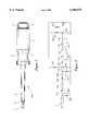
- FIG. 1is a pictorial diagram illustrating the voltage indicating tool of the present invention in the form of a screwdriver.
- FIG. 2is a schematic diagram of electronic circuitry employed in the voltage indicating tool of FIG. 1.
- FIG. 1there is shown an embodiment of an insulated electrician's screwdriver 100 that includes a blade 1 coated with insulation layers 2 and 3.
- the blade 1is fixedly retained within a handle portion 4.
- Handle 4may be fabricated to be transparent or translucent with a cavity 7 to contain the circuitry of FIG. 2.
- An opening 8 within handle 4facilitates connection of this circuitry to the blade 1.
- An end cap 6is arranged to cover an opening in the end of handle 4 using a waterproof seal 5.
- FIG. 2there is shown a schematic diagram of the circuitry employed in the voltage indicating tool of FIG. 1.
- the blade 1 of screwdriver 100 of FIG. 1used to contact the electrical circuit being tested for the presence of voltage, is connected to the input of an inverter gate 104.
- a protection diode 102 and a gain limiting resistor 103are also connected to inverter gate 104 and serve to prevent spurious or electrostatic signals from being detected.
- An inverter gate 104serves to invert the signal to a delay circuit comprising a delay diode 106, a delay resistor 108, and a delay capacitor 109.
- the delay circuitis employed to limit the signal on the input of an inverter gate 111 so that several cycles of an input signal are required to produce an output from inverter gate 111 to thereby prevent interference from spurious signals or noise spikes.
- a discharge resistor 107serves to discharge the delay circuit when no signal is present.
- the various invertersare powered through a protection diode 110, which prevents damage to an inverter in the event the polarity of a battery 124 is reversed.
- a control diode 112is reverse biased to allow an oscillator circuit comprising inverters 113, 115, and 116 and resistors 114 and 118 to oscillate when an input signal is present.
- the oscillatoris set to oscillate at a low frequency to cause the voltage indicating tool to emit a flashing light within a frequency range of 2-10 Hertz.
- the output of the oscillator circuitis fed through a current limiting resistor 119 to a driver transistor 120.
- the driver transistor 120drives a pair of LED indicators 121 and 123 through a current limiting resistor 122, resulting in the flashing of the LED indicators whenever an AC voltage is applied to blade 1.
- the circuitry of FIG. 2, as described hereinabovedraws only a few microamperes of current from battery 124 when not in use.
- LED indicators 121 and 123may be replaced by an incandescent bulb or an audible alarm, while the various inverters may be replaced with transistors or non-inverting gates, and blade 1 could be replaced with a nut driver, probe, pliers or other tool.
Landscapes
- Physics & Mathematics (AREA)
- General Physics & Mathematics (AREA)
- Measurement Of Current Or Voltage (AREA)
Abstract
Description
This invention relates generally to a device to indicate the presence of potentially dangerous voltages on electrical connections in contact with a tool or other instrument and also to indicate the presence of voltage on a conductor or electrical circuit.
Voltage indicating meters have long been available for testing circuits for the presence of potentially dangerous voltages. More recently, non-contact AC voltage detectors such as the Greenlee Model 38888 have been available. Such devices are only useful if the operator is willing to take the extra time required to test the circuit before working on it. A further problem with these prior art non-contact indicators is that they indicate the presence of an electrical field without contacting a conductor. Thus, there is no way to distinguish which of several adjacent conductors is producing the sensed electrical field. Other voltage indicating devices, such as that described in U.S. Pat. No. 4,724,382 are relatively complex involving high amplification and a constant voltage source to differentiate between full alternating voltage in the main and ripple voltages.
It is therefore a principal object of the present invention to provide a device internal to an electrical tool to alert the user to the presence of potentially dangerous voltages.
It is a further object of the present invention to provide a device for indicating the presence of potentially dangerous voltages to the user without requiring any electrical contact with the user, thereby eliminating the need for protective resistors, foil, and electrodes to insure the user's safety.
It is a further object of the present invention to provide a totally self-contained and waterproof device for indicating the presence of potentially dangerous voltages to the user, thereby eliminating external switches, lights, electrodes, foil, and contacts.
It is yet another object of the present invention to provide a device for indicating the presence of potentially dangerous voltages to the user, the device drawing sufficiently low power from its power source to allow continuous operation for several years without the need to change batteries or disconnect the power source when not in use, thereby insuring against use of the device while inoperative.
These objects are accomplished in accordance with the illustrated preferred embodiment of the invention by providing means for detecting the presence of an AC voltage on a blade or other operative portion of the tool, means for filtering and processing the detected AC voltage, and means for indicating the detected AC voltage to the user.
FIG. 1 is a pictorial diagram illustrating the voltage indicating tool of the present invention in the form of a screwdriver.
FIG. 2 is a schematic diagram of electronic circuitry employed in the voltage indicating tool of FIG. 1.
Referring now to the pictorial diagram of FIG. 1, there is shown an embodiment of an insulated electrician'sscrewdriver 100 that includes ablade 1 coated withinsulation layers blade 1 is fixedly retained within ahandle portion 4.Handle 4 may be fabricated to be transparent or translucent with a cavity 7 to contain the circuitry of FIG. 2. An opening 8 withinhandle 4 facilitates connection of this circuitry to theblade 1. Anend cap 6 is arranged to cover an opening in the end ofhandle 4 using awaterproof seal 5.
Referring now to FIG. 2, there is shown a schematic diagram of the circuitry employed in the voltage indicating tool of FIG. 1. Theblade 1 ofscrewdriver 100 of FIG. 1, used to contact the electrical circuit being tested for the presence of voltage, is connected to the input of aninverter gate 104. Aprotection diode 102 and again limiting resistor 103 are also connected toinverter gate 104 and serve to prevent spurious or electrostatic signals from being detected. Aninverter gate 104 serves to invert the signal to a delay circuit comprising adelay diode 106, adelay resistor 108, and adelay capacitor 109. The delay circuit is employed to limit the signal on the input of aninverter gate 111 so that several cycles of an input signal are required to produce an output frominverter gate 111 to thereby prevent interference from spurious signals or noise spikes. Adischarge resistor 107 serves to discharge the delay circuit when no signal is present. The various inverters are powered through aprotection diode 110, which prevents damage to an inverter in the event the polarity of abattery 124 is reversed. Acontrol diode 112 is reverse biased to allow an oscillatorcircuit comprising inverters resistors resistor 119 to adriver transistor 120. Thedriver transistor 120 drives a pair ofLED indicators resistor 122, resulting in the flashing of the LED indicators whenever an AC voltage is applied toblade 1. The circuitry of FIG. 2, as described hereinabove, draws only a few microamperes of current frombattery 124 when not in use.
Several modifications may be made to the invention as described. For example,LED indicators blade 1 could be replaced with a nut driver, probe, pliers or other tool.
Claims (7)
1. A voltage indicating tool for detecting an AC voltage impressed on an electrically conductive surface, the tool comprising:
an electrically conductive probe member for contacting the electrically conductive surface;
a voltage detection circuit, connected to the probe member, for detecting the AC voltage when the probe member comes in contact with the electrically conductive surface;
an amplifying circuit connected to the voltage detection circuit;
a signal conditioning circuit connected to the amplifying circuit, the signal conditioning circuit comprising a delay circuit for delaying an indication of the AC voltage until a plurality of cycles of the AC voltage have been detected to thereby eliminate false indications that would otherwise result from detection of spurious signals and noise spikes accompanying the AC voltage, and a reset circuit for resetting the delay circuit after the AC voltage has been removed for a predetermined period of time; and
a voltage indicator connected to the signal conditioning circuit for indicating the presence of the detected AC voltage to the user.
2. A voltage indicating tool as in claim 1 wherein the amplifying circuit includes a gain limiting resistor for varying the range of AC voltages which may be detected.
3. A voltage indicating tool as in claim 2 wherein the amplifying circuit further includes an inverter gate across which the gain limiting resistor is connected.
4. A voltage indicating tool as in claim 1 further comprising an internal power source connected to said voltage detection circuit, said amplifying circuit, said signal conditioning circuit, and said voltage indicator for supplying operating power thereto.
5. A voltage indicating tool as in claim 1 wherein the voltage indicator is operative for providing a visual indication to the user of the presence of the detected AC voltage.
6. A voltage indicating tool as in claim 5 wherein the visual indication flashes at a predetermined frequency.
7. A method for detecting and indicating an AC voltage impressed on an electrically conductive surface, the method comprising:
providing a tool having an electrically conductive probe member;
contacting the electrically conductive surface with the probe member;
detecting the AC voltage when the probe member comes in contact with the electrically conductive surface; and
indicating the presence of the detected AC voltage only after a plurality of cycles of the AC voltage have been detected to thereby eliminate false indications that would otherwise result from detection of spurious signals and noise spikes accompanying the AC voltage.
Priority Applications (1)
| Application Number | Priority Date | Filing Date | Title |
|---|---|---|---|
| US08/715,179US6100679A (en) | 1996-09-17 | 1996-09-17 | Voltage indicating instrument |
Applications Claiming Priority (1)
| Application Number | Priority Date | Filing Date | Title |
|---|---|---|---|
| US08/715,179US6100679A (en) | 1996-09-17 | 1996-09-17 | Voltage indicating instrument |
Publications (1)
| Publication Number | Publication Date |
|---|---|
| US6100679Atrue US6100679A (en) | 2000-08-08 |
Family
ID=24872981
Family Applications (1)
| Application Number | Title | Priority Date | Filing Date |
|---|---|---|---|
| US08/715,179Expired - LifetimeUS6100679A (en) | 1996-09-17 | 1996-09-17 | Voltage indicating instrument |
Country Status (1)
| Country | Link |
|---|---|
| US (1) | US6100679A (en) |
Cited By (27)
| Publication number | Priority date | Publication date | Assignee | Title |
|---|---|---|---|---|
| US20030016004A1 (en)* | 2001-07-10 | 2003-01-23 | Gary Jungwirth | Apparatus for a simplified power disturbance indicator gage with learning capability options |
| EP1336854A1 (en)* | 2002-02-18 | 2003-08-20 | Giampiero Lorenzi | Hand tool with contactless voltage tester as warning device |
| US6731218B2 (en)* | 2002-03-28 | 2004-05-04 | Actuant Corporation | Voltage sensing hand tool |
| US20040119456A1 (en)* | 2002-12-20 | 2004-06-24 | Urban Blake R. | Apparatus for accessing telecommunications networks |
| EP1450169A1 (en)* | 2003-02-24 | 2004-08-25 | Societe Anonyme Des Ets Catu | Screwdiver having high electric isolation, indicator of the presence of a phase |
| US20040222781A1 (en)* | 2003-05-09 | 2004-11-11 | Urban Blake R. | Apparatus for accessing telecommunications networks |
| US20050104735A1 (en)* | 2002-03-28 | 2005-05-19 | Luebke Thomas M. | Voltage sensing hand tool |
| US20060011022A1 (en)* | 2004-07-15 | 2006-01-19 | New Sun Far East Corp. Ltd. | Hand tool having electrified body detection alarm |
| US20060090333A1 (en)* | 2001-08-09 | 2006-05-04 | Bryan Cahill | Electrical wall switch gripping testing and installation device |
| US20060236822A1 (en)* | 2005-04-26 | 2006-10-26 | Nish Jeffery L | Threaded member driver with retention system |
| US20070079445A1 (en)* | 2004-06-08 | 2007-04-12 | Roy Siebeck | Combination tool |
| WO2007068585A1 (en)* | 2005-12-14 | 2007-06-21 | Siemens Aktiengesellschaft | Power generator as an alarm sensor |
| US20070159739A1 (en)* | 2002-03-28 | 2007-07-12 | Onachilla Michael D | Voltage Sensing Hand Tool |
| US20080058503A1 (en)* | 2001-08-09 | 2008-03-06 | Bryan Cahill | Electrical gripping testing and installation device |
| US20080196910A1 (en)* | 2000-06-20 | 2008-08-21 | Radle Patrick J | Electrical sensing device modules for attachment to power tools and drills |
| US20090056115A1 (en)* | 2001-08-09 | 2009-03-05 | Bryan Cahill | Heat Indicating Electrical Wall Fixture Gripping Testing and Installation Device |
| US20090257222A1 (en)* | 2008-04-09 | 2009-10-15 | Jones Mike N | Slidably attachable non-contact voltage detector |
| US20090272652A1 (en)* | 2008-05-05 | 2009-11-05 | Tennant Company | Charge movement detector for electrochemically activated liquids |
| US20100033190A1 (en)* | 2008-08-08 | 2010-02-11 | Industrial Control & Electrical Pty Ltd | Electrical test device |
| US20100308852A1 (en)* | 2009-06-03 | 2010-12-09 | Fluke Corporation | Shielded antenna for system test of a non-contact voltage detector |
| US20130193991A1 (en)* | 2009-11-20 | 2013-08-01 | Smc Electrical Products, Inc. | High Voltage Sensing Capacitor and Indicator Device |
| US20130239335A1 (en)* | 2012-03-19 | 2013-09-19 | Wayne Anderson | Electric testing device and method for hand tools having testing mechanisms |
| JP2017227630A (en)* | 2016-06-22 | 2017-12-28 | 致茂電子股▲分▼有限公司Chroma Ate Inc. | Electric probe and jig |
| US10126335B2 (en) | 2014-09-22 | 2018-11-13 | Panduit Corp. | System for the verification of the absence of voltage |
| NL2020795B1 (en)* | 2018-04-19 | 2019-10-28 | Krabbe Electronics | Voltage tester |
| US11215646B2 (en) | 2019-04-22 | 2022-01-04 | Panduit Corp. | Absence of voltage detection device |
| USD1081421S1 (en)* | 2023-04-17 | 2025-07-01 | Suzhou Techmax E-Commerce Co., Ltd. | Test light |
Citations (16)
| Publication number | Priority date | Publication date | Assignee | Title |
|---|---|---|---|---|
| US2710397A (en)* | 1950-06-24 | 1955-06-07 | George E Foster | Electrical measuring apparatus |
| US3829776A (en)* | 1973-07-31 | 1974-08-13 | E Lozoya | Pen type voltmeter |
| US3831089A (en)* | 1971-08-20 | 1974-08-20 | G Pearce | Continuity tester |
| US4004223A (en)* | 1975-06-16 | 1977-01-18 | Cohen Samuel G | Audible resistance or voltage tester |
| US4027236A (en)* | 1976-07-14 | 1977-05-31 | Triple S Products Company | Voltage and continuity checker |
| US4205264A (en)* | 1978-04-25 | 1980-05-27 | Charles Gold | High impedance electrical testing instrument for AC and DC voltage detection and continuity testing |
| US4225817A (en)* | 1978-10-10 | 1980-09-30 | Kahlden Gerald D | Combined continuity and voltage test instrument |
| US4233560A (en)* | 1978-08-24 | 1980-11-11 | Blenman Orman L | Electrical apparatus for testing voltage, polarity and continuity |
| US4614940A (en)* | 1985-10-21 | 1986-09-30 | Southwest Research Institute | Micropower DC voltage indicator |
| US4724382A (en)* | 1984-10-11 | 1988-02-09 | Hubertus Schauerte | Testing instrument for detectlng alternating voltages in mains and alternating electromagnetic fields in the vicinity of voltage-carrying conductors |
| US5065142A (en)* | 1990-05-23 | 1991-11-12 | Service Machine Company | Voltage pickup circuit and flashing display for high voltage indicator device, and input electrode therefor |
| US5105181A (en)* | 1990-08-17 | 1992-04-14 | Hydro-Quebec | Method and electrical measuring apparatus for analyzing the impedance of the source of an actual alternating voltage |
| US5202640A (en)* | 1991-06-03 | 1993-04-13 | International Business Machines Corporation | Capacitance and leakage test method and apparatus |
| US5274336A (en)* | 1992-01-14 | 1993-12-28 | Hewlett-Packard Company | Capacitively-coupled test probe |
| US5285163A (en)* | 1992-05-07 | 1994-02-08 | Liotta William A | Electrical cable continuity and voltage tester |
| US5642052A (en)* | 1995-06-05 | 1997-06-24 | Etcon Corporation | Hand-held tester for receptacle ground fault circuit interrupters |
- 1996
- 1996-09-17USUS08/715,179patent/US6100679A/ennot_activeExpired - Lifetime
Patent Citations (16)
| Publication number | Priority date | Publication date | Assignee | Title |
|---|---|---|---|---|
| US2710397A (en)* | 1950-06-24 | 1955-06-07 | George E Foster | Electrical measuring apparatus |
| US3831089A (en)* | 1971-08-20 | 1974-08-20 | G Pearce | Continuity tester |
| US3829776A (en)* | 1973-07-31 | 1974-08-13 | E Lozoya | Pen type voltmeter |
| US4004223A (en)* | 1975-06-16 | 1977-01-18 | Cohen Samuel G | Audible resistance or voltage tester |
| US4027236A (en)* | 1976-07-14 | 1977-05-31 | Triple S Products Company | Voltage and continuity checker |
| US4205264A (en)* | 1978-04-25 | 1980-05-27 | Charles Gold | High impedance electrical testing instrument for AC and DC voltage detection and continuity testing |
| US4233560A (en)* | 1978-08-24 | 1980-11-11 | Blenman Orman L | Electrical apparatus for testing voltage, polarity and continuity |
| US4225817A (en)* | 1978-10-10 | 1980-09-30 | Kahlden Gerald D | Combined continuity and voltage test instrument |
| US4724382A (en)* | 1984-10-11 | 1988-02-09 | Hubertus Schauerte | Testing instrument for detectlng alternating voltages in mains and alternating electromagnetic fields in the vicinity of voltage-carrying conductors |
| US4614940A (en)* | 1985-10-21 | 1986-09-30 | Southwest Research Institute | Micropower DC voltage indicator |
| US5065142A (en)* | 1990-05-23 | 1991-11-12 | Service Machine Company | Voltage pickup circuit and flashing display for high voltage indicator device, and input electrode therefor |
| US5105181A (en)* | 1990-08-17 | 1992-04-14 | Hydro-Quebec | Method and electrical measuring apparatus for analyzing the impedance of the source of an actual alternating voltage |
| US5202640A (en)* | 1991-06-03 | 1993-04-13 | International Business Machines Corporation | Capacitance and leakage test method and apparatus |
| US5274336A (en)* | 1992-01-14 | 1993-12-28 | Hewlett-Packard Company | Capacitively-coupled test probe |
| US5285163A (en)* | 1992-05-07 | 1994-02-08 | Liotta William A | Electrical cable continuity and voltage tester |
| US5642052A (en)* | 1995-06-05 | 1997-06-24 | Etcon Corporation | Hand-held tester for receptacle ground fault circuit interrupters |
Cited By (44)
| Publication number | Priority date | Publication date | Assignee | Title |
|---|---|---|---|---|
| US20080196910A1 (en)* | 2000-06-20 | 2008-08-21 | Radle Patrick J | Electrical sensing device modules for attachment to power tools and drills |
| US20030016004A1 (en)* | 2001-07-10 | 2003-01-23 | Gary Jungwirth | Apparatus for a simplified power disturbance indicator gage with learning capability options |
| US7106045B2 (en) | 2001-07-10 | 2006-09-12 | Uppi Corporation | Apparatus for a simplified power disturbance indicator gage with learning capability options |
| US20080058503A1 (en)* | 2001-08-09 | 2008-03-06 | Bryan Cahill | Electrical gripping testing and installation device |
| US20090056115A1 (en)* | 2001-08-09 | 2009-03-05 | Bryan Cahill | Heat Indicating Electrical Wall Fixture Gripping Testing and Installation Device |
| US7703195B2 (en) | 2001-08-09 | 2010-04-27 | Pluggrip Products, Llc | Methods of manipulating electrical wall fixtures |
| US20060090333A1 (en)* | 2001-08-09 | 2006-05-04 | Bryan Cahill | Electrical wall switch gripping testing and installation device |
| EP1336854A1 (en)* | 2002-02-18 | 2003-08-20 | Giampiero Lorenzi | Hand tool with contactless voltage tester as warning device |
| US20050104735A1 (en)* | 2002-03-28 | 2005-05-19 | Luebke Thomas M. | Voltage sensing hand tool |
| US20070159739A1 (en)* | 2002-03-28 | 2007-07-12 | Onachilla Michael D | Voltage Sensing Hand Tool |
| US7468674B2 (en) | 2002-03-28 | 2008-12-23 | Actuant Corporation | Voltage sensing hand tool |
| US6844819B2 (en) | 2002-03-28 | 2005-01-18 | Actuant Corporation | Voltage sensing hand tool |
| US6731218B2 (en)* | 2002-03-28 | 2004-05-04 | Actuant Corporation | Voltage sensing hand tool |
| US20040183689A1 (en)* | 2002-03-28 | 2004-09-23 | Luebke Thomas M. | Voltage sensing hand tool |
| US7295130B2 (en)* | 2002-03-28 | 2007-11-13 | Actuant Corporation | Voltage sensing hand tool |
| US7073414B2 (en) | 2002-12-20 | 2006-07-11 | Bellsouth Intellectual Property Corporation | Apparatus for accessing telecommunications networks |
| US20040119456A1 (en)* | 2002-12-20 | 2004-06-24 | Urban Blake R. | Apparatus for accessing telecommunications networks |
| FR2851490A1 (en)* | 2003-02-24 | 2004-08-27 | Catu Ets | HIGH INSULATION ELECTRICAL SCREWDRIVER, PHASE PRESENCE INDICATOR |
| EP1450169A1 (en)* | 2003-02-24 | 2004-08-25 | Societe Anonyme Des Ets Catu | Screwdiver having high electric isolation, indicator of the presence of a phase |
| US6886432B2 (en) | 2003-05-09 | 2005-05-03 | Bellsouth Intellectual Property Corporation | Apparatus for accessing telecommunications networks |
| US20040222781A1 (en)* | 2003-05-09 | 2004-11-11 | Urban Blake R. | Apparatus for accessing telecommunications networks |
| US20070079445A1 (en)* | 2004-06-08 | 2007-04-12 | Roy Siebeck | Combination tool |
| US20060011022A1 (en)* | 2004-07-15 | 2006-01-19 | New Sun Far East Corp. Ltd. | Hand tool having electrified body detection alarm |
| US20060236822A1 (en)* | 2005-04-26 | 2006-10-26 | Nish Jeffery L | Threaded member driver with retention system |
| WO2007068585A1 (en)* | 2005-12-14 | 2007-06-21 | Siemens Aktiengesellschaft | Power generator as an alarm sensor |
| US20090257222A1 (en)* | 2008-04-09 | 2009-10-15 | Jones Mike N | Slidably attachable non-contact voltage detector |
| US8193802B2 (en) | 2008-04-09 | 2012-06-05 | Milwaukee Electric Tool Corporation | Slidably attachable non-contact voltage detector |
| US20090272652A1 (en)* | 2008-05-05 | 2009-11-05 | Tennant Company | Charge movement detector for electrochemically activated liquids |
| WO2009137497A3 (en)* | 2008-05-05 | 2010-02-25 | Tennant Company | Charge movement detector for electrochemically activated liquids |
| US8062499B2 (en) | 2008-05-05 | 2011-11-22 | Tennant Compnay | Charge movement detector for electrochemically activated liquids |
| US20100033190A1 (en)* | 2008-08-08 | 2010-02-11 | Industrial Control & Electrical Pty Ltd | Electrical test device |
| US8415955B2 (en) | 2008-08-08 | 2013-04-09 | Industrial Control & Electrical Pty Ltd | Electrical test device |
| US8581609B2 (en)* | 2009-06-03 | 2013-11-12 | Fluke Corporation | Shielded antenna for system test of a non-contact voltage detector |
| US20100308852A1 (en)* | 2009-06-03 | 2010-12-09 | Fluke Corporation | Shielded antenna for system test of a non-contact voltage detector |
| US20130193991A1 (en)* | 2009-11-20 | 2013-08-01 | Smc Electrical Products, Inc. | High Voltage Sensing Capacitor and Indicator Device |
| US20130239335A1 (en)* | 2012-03-19 | 2013-09-19 | Wayne Anderson | Electric testing device and method for hand tools having testing mechanisms |
| US9056392B2 (en)* | 2012-03-19 | 2015-06-16 | Wayne Anderson | Electric testing device and method for hand tools having testing mechanisms |
| US20150241475A1 (en)* | 2012-03-19 | 2015-08-27 | Wayne Anderson | Electric testing device and method for hand tools having testing mechanisms |
| US10126335B2 (en) | 2014-09-22 | 2018-11-13 | Panduit Corp. | System for the verification of the absence of voltage |
| JP2017227630A (en)* | 2016-06-22 | 2017-12-28 | 致茂電子股▲分▼有限公司Chroma Ate Inc. | Electric probe and jig |
| NL2020795B1 (en)* | 2018-04-19 | 2019-10-28 | Krabbe Electronics | Voltage tester |
| US11215646B2 (en) | 2019-04-22 | 2022-01-04 | Panduit Corp. | Absence of voltage detection device |
| US11946954B2 (en) | 2019-04-22 | 2024-04-02 | Panduit Corp. | Absence of voltage detection device |
| USD1081421S1 (en)* | 2023-04-17 | 2025-07-01 | Suzhou Techmax E-Commerce Co., Ltd. | Test light |
Similar Documents
| Publication | Publication Date | Title |
|---|---|---|
| US6100679A (en) | Voltage indicating instrument | |
| US6812685B2 (en) | Auto-selecting, auto-ranging contact/noncontact voltage and continuity tester | |
| US5952820A (en) | Foreign voltage detector | |
| US6844819B2 (en) | Voltage sensing hand tool | |
| CA2089664A1 (en) | Method and Electrical Measuring Apparatus for Analyzing the Impedance of the Source of an Actual Alternating Voltage | |
| US3962630A (en) | Electrical continuity and voltage testing device | |
| KR970705032A (en) | AC Power Outlet Grounding Characteristics and AC Power Outlet Ground Integrity and Wire Test Circuit Device | |
| JPS59116557A (en) | Sensor device for voltage | |
| US6731102B2 (en) | Electronic test instrument with extended functions | |
| US4205264A (en) | High impedance electrical testing instrument for AC and DC voltage detection and continuity testing | |
| US3437928A (en) | Self-contained test probe with indicator lamp responsive to continuous or pulsed voltages | |
| US5319306A (en) | Portable electrical line tester using audible tones to indicate voltage | |
| US10466280B1 (en) | Enhanced circuit and method for detecting hazardous foreign voltages on conductors | |
| JPS6490831A (en) | Electronic direction indicator | |
| US5841357A (en) | Battery electrolyte monitor | |
| US4504781A (en) | Voltage wand | |
| US3639833A (en) | Solid-state voltage and fault detector means having integral circuit integrity indicators | |
| US4322782A (en) | Flashlight | |
| JP3092996B2 (en) | Digital Multimeters | |
| JP2621217B2 (en) | Electronic device having battery performance determination system | |
| SE8500205D0 (en) | DEVICE FOR TESTLESS TESTING THE PRESENCE OF ELECTRIC VOLTAGE | |
| DE50301858D1 (en) | DEVICE FOR CONNECTIVE LIMIT LEVEL MEASUREMENT | |
| KR0128540Y1 (en) | Multimeter Hazard Warning Device | |
| GB2117126A (en) | Circuit testing device | |
| JPS6469962A (en) | Detecting apparatus of contact resistance |
Legal Events
| Date | Code | Title | Description |
|---|---|---|---|
| AS | Assignment | Owner name:TASCO, INC., COLORADO Free format text:ASSIGNMENT OF ASSIGNORS INTEREST;ASSIGNOR:MCCASLAND, THOMAS A.;REEL/FRAME:008224/0481 Effective date:19960912 | |
| STCF | Information on status: patent grant | Free format text:PATENTED CASE | |
| REMI | Maintenance fee reminder mailed | ||
| FPAY | Fee payment | Year of fee payment:4 | |
| SULP | Surcharge for late payment | ||
| REMI | Maintenance fee reminder mailed | ||
| FPAY | Fee payment | Year of fee payment:8 | |
| SULP | Surcharge for late payment | Year of fee payment:7 | |
| FPAY | Fee payment | Year of fee payment:12 |