US6100664A - Sub-miniature high efficiency battery charger exploiting leakage inductance of wall transformer power supply, and method therefor - Google Patents
Sub-miniature high efficiency battery charger exploiting leakage inductance of wall transformer power supply, and method thereforDownload PDFInfo
- Publication number
- US6100664A US6100664AUS09/282,726US28272699AUS6100664AUS 6100664 AUS6100664 AUS 6100664AUS 28272699 AUS28272699 AUS 28272699AUS 6100664 AUS6100664 AUS 6100664A
- Authority
- US
- United States
- Prior art keywords
- current
- battery
- switch
- microprocessor
- transformer
- Prior art date
- Legal status (The legal status is an assumption and is not a legal conclusion. Google has not performed a legal analysis and makes no representation as to the accuracy of the status listed.)
- Expired - Lifetime
Links
- 238000000034methodMethods0.000titleclaimsdescription12
- 230000010355oscillationEffects0.000claimsabstractdescription8
- 230000007423decreaseEffects0.000claimsdescription12
- 230000001419dependent effectEffects0.000claimsdescription10
- 239000003990capacitorSubstances0.000claimsdescription8
- 230000008878couplingEffects0.000claimsdescription5
- 238000010168coupling processMethods0.000claimsdescription5
- 238000005859coupling reactionMethods0.000claimsdescription5
- 238000012544monitoring processMethods0.000claimsdescription5
- 230000008569processEffects0.000description6
- 238000006243chemical reactionMethods0.000description5
- 238000010586diagramMethods0.000description4
- 238000004146energy storageMethods0.000description3
- 230000006870functionEffects0.000description3
- 238000013459approachMethods0.000description2
- 238000004364calculation methodMethods0.000description2
- 230000001413cellular effectEffects0.000description2
- 230000036039immunityEffects0.000description2
- 230000001939inductive effectEffects0.000description2
- 230000003068static effectEffects0.000description2
- 230000002459sustained effectEffects0.000description2
- 230000003466anti-cipated effectEffects0.000description1
- 238000009529body temperature measurementMethods0.000description1
- 230000008859changeEffects0.000description1
- 230000002950deficientEffects0.000description1
- 238000007599dischargingMethods0.000description1
- 230000005669field effectEffects0.000description1
- 230000004044responseEffects0.000description1
Images


Classifications
- H—ELECTRICITY
- H02—GENERATION; CONVERSION OR DISTRIBUTION OF ELECTRIC POWER
- H02J—CIRCUIT ARRANGEMENTS OR SYSTEMS FOR SUPPLYING OR DISTRIBUTING ELECTRIC POWER; SYSTEMS FOR STORING ELECTRIC ENERGY
- H02J7/00—Circuit arrangements for charging or depolarising batteries or for supplying loads from batteries
- H02J7/02—Circuit arrangements for charging or depolarising batteries or for supplying loads from batteries for charging batteries from AC mains by converters
- H—ELECTRICITY
- H02—GENERATION; CONVERSION OR DISTRIBUTION OF ELECTRIC POWER
- H02J—CIRCUIT ARRANGEMENTS OR SYSTEMS FOR SUPPLYING OR DISTRIBUTING ELECTRIC POWER; SYSTEMS FOR STORING ELECTRIC ENERGY
- H02J2207/00—Indexing scheme relating to details of circuit arrangements for charging or depolarising batteries or for supplying loads from batteries
- H02J2207/20—Charging or discharging characterised by the power electronics converter
- Y—GENERAL TAGGING OF NEW TECHNOLOGICAL DEVELOPMENTS; GENERAL TAGGING OF CROSS-SECTIONAL TECHNOLOGIES SPANNING OVER SEVERAL SECTIONS OF THE IPC; TECHNICAL SUBJECTS COVERED BY FORMER USPC CROSS-REFERENCE ART COLLECTIONS [XRACs] AND DIGESTS
- Y02—TECHNOLOGIES OR APPLICATIONS FOR MITIGATION OR ADAPTATION AGAINST CLIMATE CHANGE
- Y02B—CLIMATE CHANGE MITIGATION TECHNOLOGIES RELATED TO BUILDINGS, e.g. HOUSING, HOUSE APPLIANCES OR RELATED END-USER APPLICATIONS
- Y02B40/00—Technologies aiming at improving the efficiency of home appliances, e.g. induction cooking or efficient technologies for refrigerators, freezers or dish washers
Definitions
- the present inventionis directed to battery chargers, and more specifically to a battery charger that achieves high efficiency switch mode control of battery charging current using a simplified circuit topology that is inexpensive and easily packaged in a sub-miniature package.
- Battery chargersare used to charge batteries of electronic appliances, such as portable computers, cellular telephones, pagers, etc. When used in connection with very small portable electronic devices, such as cellular telephones and pagers, it is preferable that the battery charger device be as small and portable as possible.
- Battery chargersare known that use an ON-OFF control whereby the power source is alternatively connected and disconnected in order to generate an average charging current for the battery.
- This type of battery charging systemis generally restricted to a single average value of charging current determined by the external power supply.
- EMIelectromagnetic interference
- FIG. 1is a block diagram of the battery charger according to the present invention connected to a wall transformer.
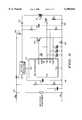
- FIG. 2is an electrical schematic diagram of the battery charger according to the present invention.
- FIG. 3is a flow chart showing the operation of the battery charger of the present invention.
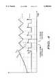
- FIG. 4is a graphical diagram showing the waveforms of the transformer output current and the battery charging current.
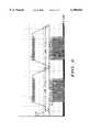
- FIG. 5is a graphical diagram showing the transformer output current and the battery charging current pulses over a longer period of time than shown in FIG. 4.
- the battery charger 100has input terminals 101 and 102 that connect to the output of a standard wall transformer power supply 20, and output terminals 103 and 104 that connect to a battery 30 to be charged.
- the diode 140may be any diode similar to a Schottky diode that has a low forward voltage.
- the battery charger 100functions with a standard low cost unregulated linear (line frequency) wall transformer 20 having a rectified power supply. Of importance is that the battery charger 100 does not require any bulky filter capacitor or active (with a bulky inductor) output regulator. Rather, the battery charger 100 exploits the inherent secondary leakage inductance of the wall transformer 20 as an inductive energy storage element for accomplishing switch mode power conversion. In addition, the inherent energy storage capability and "capacitor-like" characteristics of the battery 30 are exploited to stabilize the charging voltage for switch mode power conversion.
- the wall transformer power supply 20 used with the battery charger 100 of the present inventionis lower in output voltage and higher in output current than conventionally used with prior art step down (buck) type battery chargers.
- the transformer voltageis boosted by the power conversion system of the battery charger 100 to achieve the correct charging voltage. Nevertheless, the overall transformer size and cost is comparable to that used with a conventional step down charger.
- the input terminals 101 and 102are connected to the rectified output of the transformer 20.
- the secondary of the transformer 20has some inherent leakage inductance represented by the inductor L shown connected to the input terminal 101.
- a voltage dividerconsisting of resistors R1 and R2 is connected across the input terminals 101 and 102.
- Capacitor C1 connected in parallel with resistor R2is provided for electromagnetic interference (EMI) and static discharge immunity as is well known in the art.
- a non-linear resistor R7is connected between the input terminal 101 and the Schottky diode 140.
- the microprocessor 110functions as a controller for the battery charger 100.
- a software program that is executed by the microprocessor 110 to control the battery chargeis stored in on-board memory or alternatively a separate memory.
- the voltage regulator 120is connected to the other terminal of the Schottky diode 140 and to a V DD pin of the microprocessor 110.
- Input pin AN1 of the microprocessor 110is connected the node between resistors R1 and R2 to sense a bias voltage for determining when there is input power available at the input terminals 101 and 102, as will be described hereinafter.
- the switch 130is a low cost N-channel field effect transistor (FET) having a gate terminal (G), source terminal (S) and drain terminal (D).
- the gate terminal of the switch 130is connected to a GATE pin of the microprocessor 110.
- the drain of the switch 130is connected to a point between the non-linear resistor R7 and the Schottky diode 140, and the source of the switch 130 is connected to one end of the current sense resistor 150 (corresponding to resistor R3).
- the battery charger 100has three modes of operation: Standby, Backup and Charging.
- a software programis stored in an on-board memory (not shown) in the microprocessor 110 that is executed by the microprocessor 110 to control the operation of the battery charger 100.
- the software programis referred to hereinafter as the power switch mode control software program.
- FIG. 3is a flow chart that depicts the logical flow of the power switch mode control software program 200 executed by the microprocessor 110 in the course of controlling the battery charger 100.
- the microprocessor 110determines whether power is available from the transformer 20. When the battery charger 100 is connected to the transformer 20 and the transformer 20 is plugged into a wall outlet, there will be power available from the transformer 20. The microprocessor 110 makes this determination by measuring voltage at pin AN1 which corresponds to the voltage across resistor R1 and capacitor C1. If there is a significant voltage at pin AN1 then the power is available from the transformer and the process continues. If it is determined that no power is available from the transformer (either the battery charger is not connected to it or the transformer is not plugged into a power supply), then the process enters the StandBy Mode to be described hereinafter.
- step 210it is determined whether the battery 30 has some residual charge (a predetermined value of 2.0 volts or greater) on it or whether it is completely discharged.
- the microprocessor 110makes this determination by measuring the voltage across resistor R5. If there is at least a residual charge on the battery 30, then the process proceeds to the charging mode described below.
- the transformer 20is intentionally designed to satisfy this criterion. Therefore, initially there is no current flow from the transformer 20 to the battery 30. However, there is sufficient voltage from the transformer 20 to develop a bias voltage across resistor R2 of the voltage divider R1 and R2.
- the microprocessor 110detects the bias voltage level at pin AN1, and from this signal knows that there is power available. In response, the microprocessor 110 "wakes-up" and enters a charging mode of operation.
- the microprocessor 110begins a power switch mode charging cycle by turning ON the switch 130 in step 215.
- Switch 130when turned ON, shorts the output of the transformer 20 and therefore current begins flowing in a current path from the input terminal 101, through resistor R7, through the drain and source of switch 130, through current sense resistor 150 to the output terminal 102.
- the residual voltage of the battery 30powers the microprocessor 110 via the voltage regulator 120.
- the rate at which the short circuit current through the switch 130 increasesis determined by the secondary leakage inductance L of the transformer 20.
- This inductanceis fairly large for this type of transformer, and therefore the current in the short-circuit path builds up at a relatively slow rate compared to typical switch mode converters.
- the rise of current with timeis approximately linear.
- the time interval when the switch 130 is ONis termed the "conduction interval" as indicated in FIG. 3.
- step 220the microprocessor 110 continuously monitors the voltage across the current sense resistor 150. This signal is coupled to a programmable voltage comparator inside the microprocessor 110. The microprocessor 110 sets thresholds to which the voltage across the current sense resistor 150 is compared. These thresholds are variable and are established by the power switch mode control software program stored in the microprocessor 110. During the conduction interval, the microprocessor 110 compares the voltage across the current sense resistor with a first or upper threshold. The first or upper threshold is, for example, approximately four times the desired average charging current for the battery 30. In step 225, the microprocessor 110 determines when the upper threshold is reached. If the upper threshold is not reached, then the process repeats from step 220 and the microprocessor 10 continues to monitor the voltage across the current sense resistor 150.
- a first or upper thresholdis, for example, approximately four times the desired average charging current for the battery 30.
- step 230the microprocessor 110 immediately turns off the switch 130. Since current flowing in the leakage inductance L of the transformer 20 cannot change instantaneously when switch 130 is switched OFF, the current from the transformer follows a new path through the Schottky diode 140 and into the battery 30.
- the inductive energy stored by the leakage inductance L of the transformer 20momentarily supports current flow through the Schottky diode 140 and the battery 30.
- the effective capacitance of the batterycauses the battery voltage to remain essentially constant during this pulse of current, called a charging current pulse.
- the leakage inductance L of the transformer 20is delivering energy, the current begins to decrease in the charging path as the leakage energy dissipates.
- the rate of decrease of charging currentis determined by value of the secondary leakage inductance L of the transformer 20, and is relatively linear and at a slow rate compared to more conventional switch mode converters.
- the interval of current flow supported by the transformer leakage energy when the switch 130 is turned OFFis called a "flyback interval" as indicated in FIG. 3.
- the power switch mode control algorithm in the microprocessor 110changes the programmable comparator threshold to a different value corresponding to a second or lower threshold.
- the lower thresholdis approximately three times (as opposed to four times) the desired average charging current.
- the microprocessor 110monitors the voltage across the current sense resistor and compares it with the lower threshold value. When the lower threshold is reached, a new conduction interval for the switch 130 is initiated by the microprocessor 110, and the process repeats from step 215 as explained above. Otherwise, the current is allowed to decrease until the microprocessor 110 eventually determines that it has reached the lower threshold value.
- the secondary current (I S ) in the transformer 20is forced by the microprocessor 110 to oscillate between two values established by upper and lower thresholds (T u and T L ).
- upper and lower thresholdsT u and T L .
- the upper and lower thresholds of instantaneous current for each charging current pulseare defined by the power switch mode control algorithm executed by the microprocessor 110. The rate of decrease of current between these thresholds is approximately linear, and the charge current pulse is approximately trapezoidal in shape as shown in FIG. 4.
- the microprocessor 110In addition to controlling the peak current, the microprocessor 110 continuously and periodically calculates the actual average charging current. This is readily accomplished because the current changes relatively slowly and in a nearly linear manner between the upper and lower thresholds. By approximating that the current decreases in a nearly linear manner during the flyback interval, the microprocessor 110 can accurately calculate the actual average charging current for any arbitrary time period. Alternatively, a "running average" can be calculated for the actual average current in which the most recent average calculation for a given period of time is given a weighted value that is combined the average for all previous calculations.
- a further feature of the present inventionis that the actual average current (calculated periodically or as a running average) is used as a feedback parameter in a closed loop control system to regulate the value of the average charging current. After calculating the average current, it is used as an input to a closed loop software current regulator control algorithm executed by the microprocessor 110.
- the microprocessorcontinuously adjusts the programmable upper and lower thresholds so as to keep the actual average current at precisely the desired value.
- the Standby Mode of operation of the battery charger 100occurs when the battery 30 is connected to the charger 100, but no input power is available.
- This conditionis determined in step 205 when the microprocessor 110 determines that no power is available from the transformer 20.
- the microprocessor 110goes into a standby sleep mode. In this mode, the clock of the microprocessor 110 runs at a reduced frequency and the microprocessor operations are minimized to reduced current drain.
- the switch 130remains OFF in this mode, and the logic voltage at resistor R6 is turned off to avoid any current drain of the battery 30 through this resistor.
- the microprocessordetermines when the standby sleep mode should be activated or deactivated by monitoring the input voltage from the divider R1 and R2.
- step 210The battery charger 100 has a BackUp Mode of operation in step 260 that charges the battery 30 until sufficient "residual" charge is available to run the voltage regulator 120 that powers the microprocessor 110.
- the diode 140begins to conduct current directly from the transformer output to bring the battery voltage quickly up to a residual voltage level.
- the charging current during the BackUp Modeis not controlled as previously described, but rather is limited only by the transformer impedance, the current sense resistor 150 and the non-linear resistor R7.
- Resistor R7is a non-linear temperature sensitive current limiting resistor having a positive temperature coefficient, such as that sold under the tradename Polyswitch and manufactured by Raychem, Inc. As the current through resistor R7 increases and its temperature rises, its resistance increases. This in turn causes the current to decrease. By proper selection of the temperature characteristics of the resistor R7, it effectively becomes a passive current regulator. The accuracy of the charging current control of the resistor R7 is sufficient to control the charging current until the residual voltage in the battery 30 rises to a more acceptable level.
- the nonlinear characteristics of the resistor R7also provide current limiting protection to the battery charger 100 in the event that the output of the battery charger 100 is shorted, or if a shorted or defective battery is connected to the battery charger 100. Furthermore, the non-linear temperature characteristics of the resistor R7 may be significantly enhanced by thermally coupling the resistor R7 to the diode 140.
- the charging current during the BackUp Modemight typically be 1/20 to 1/4 of the normal charging current for the battery 30. This low charging current value is chosen to limit the power dissipation in resistor R7 to a reasonably low value. At this charge rate, the BackUp Mode of charging will typically last only a few minutes before sufficient residual charge is achieved to begin normal operation with the microprocessor 110.
- the other components of the battery charger 100 shown in FIG. 2are well known in the art.
- the resistor R8is a thermistor within the battery 30 used, in conjunction with resistor R6, to provide a temperature signal to an analog-to-digital (A/D) converter input at the TEMP pin of the microprocessor 110.
- Resistor R6is powered by a digital output from the microprocessor 110 when it is necessary to make a temperature measurement of the battery. This avoids a discharge path through resistor R6 for the battery current during a sleep mode.
- the battery voltageis measured by a resistor divider R4 and R5, which provides a signal to an A/D input at the AN3 pin of the microprocessor 110.
- the battery charging algorithm executed by the microprocessoruses the battery temperature and voltage information to establish the correct charging current profile, as is well known in the art.
- Capacitors C1, C2, C3, C4 and C5provide both EMI and static discharge immunity.
- the battery charger 100 according to the present inventionis intended to function with most battery back types and is capable of meeting most host device requirements.
- an optional electrochemical "super” capacitor C6(FIG. 2) may be used to reduce voltage ripple while retaining the advantages of miniaturization and simplicity.
- Such a “super” capacitorwould have large storage capacity, but nevertheless be relatively small in size so as not to compromise the small package of the battery charger 100 according to the present invention.
- the present inventionis directed to a battery charger comprising input terminals for connection to a wall transformer power supply to receive a supply of current; output terminals for connection to a battery to be charged; a switch coupled to the input terminals that controls flow of current from the transformer either to the output terminals for charging the battery or to ground; a resistor connected in series with the switch and the input terminals; a Schottky diode connected between the input terminals and output terminals so as to permit current flow to the input terminals when the voltage at the input terminals is greater than the voltage at the output terminals; a controller coupled to the switch to control whether the switch is open or closed, coupled to the resistor to monitor current flow through the resistor and coupled to the output terminals to monitor voltage in the battery, the controller determining when there is sufficient residual charge in the battery to initiate a charging mode comprising oscillation between first and second intervals, during the first interval the controller closing the switch and creating a short-circuit current path through the switch whereby current flows through the switch and increases at a rate dependent on
- the present inventionis directed to A method for charging a battery with current from a wall transformer power supply, comprising steps of: (a) coupling a switch to receive current from a wall transformer power supply; (b) closing the switch so that current from the wall transformer power supply is short-circuited through the switch and permitted to increase at a rate dependent on a secondary leakage inductance of the wall transformer; (c) monitoring the current through the switch and determining when it reaches a first threshold; (d) opening the switch when the current through it reaches the first threshold, thereby coupling current from the wall transformer power supply to the battery and allowing the current to decrease at a rate dependent on the secondary leakage inductance of the wall transformer; (e) monitoring the current through the switch and determining when it reaches a second threshold; (f) repeating steps (b)-(e).
Landscapes
- Engineering & Computer Science (AREA)
- Power Engineering (AREA)
- Charge And Discharge Circuits For Batteries Or The Like (AREA)
Abstract
Description
Claims (19)
Priority Applications (1)
| Application Number | Priority Date | Filing Date | Title |
|---|---|---|---|
| US09/282,726US6100664A (en) | 1999-03-31 | 1999-03-31 | Sub-miniature high efficiency battery charger exploiting leakage inductance of wall transformer power supply, and method therefor |
Applications Claiming Priority (1)
| Application Number | Priority Date | Filing Date | Title |
|---|---|---|---|
| US09/282,726US6100664A (en) | 1999-03-31 | 1999-03-31 | Sub-miniature high efficiency battery charger exploiting leakage inductance of wall transformer power supply, and method therefor |
Publications (1)
| Publication Number | Publication Date |
|---|---|
| US6100664Atrue US6100664A (en) | 2000-08-08 |
Family
ID=23082859
Family Applications (1)
| Application Number | Title | Priority Date | Filing Date |
|---|---|---|---|
| US09/282,726Expired - LifetimeUS6100664A (en) | 1999-03-31 | 1999-03-31 | Sub-miniature high efficiency battery charger exploiting leakage inductance of wall transformer power supply, and method therefor |
Country Status (1)
| Country | Link |
|---|---|
| US (1) | US6100664A (en) |
Cited By (27)
| Publication number | Priority date | Publication date | Assignee | Title |
|---|---|---|---|---|
| US6525512B2 (en)* | 2000-04-03 | 2003-02-25 | Cochlear Limited | Medically implantable energy storage system having safe recharging capabilities |
| US6529389B2 (en) | 2000-04-06 | 2003-03-04 | Aria Corporation | Universal input miniature power supply with a single split transformer primary winding |
| US6570363B2 (en)* | 2000-04-03 | 2003-05-27 | Cochlear Limited | Medically implantable energy storage system having safe recharging capabilities |
| US20040164708A1 (en)* | 2003-02-21 | 2004-08-26 | Dusan Veselic | Circuit and method of operation for an electrical power supply |
| US20040251745A1 (en)* | 2003-06-13 | 2004-12-16 | Alcatel | Power switching system |
| US20050077866A1 (en)* | 2003-10-08 | 2005-04-14 | Energy & Engine Technology Corporation | Method and system for managing battery power |
| US20050110463A1 (en)* | 2003-11-26 | 2005-05-26 | Joseph Patino | Charging system and method |
| US20060131885A1 (en)* | 2002-11-21 | 2006-06-22 | Energy And Engine Technology Corporation | Auxiliary heating and air conditioning unit for a diesel powered transport vehicle |
| US20070109827A1 (en)* | 2003-12-10 | 2007-05-17 | Delacruz Moises | Ac to dc converter circuit |
| US20070132427A1 (en)* | 2005-12-13 | 2007-06-14 | Research In Motion Limited | Charging and power supply for mobile devices |
| EP1798835A1 (en)* | 2005-12-13 | 2007-06-20 | Research In Motion Limited | Charger and Power Supply for Mobile Devices |
| US20080054853A1 (en)* | 2006-08-29 | 2008-03-06 | Agere Systems, Inc. | Software based thermal charging regulation loop |
| WO2008118477A1 (en)* | 2007-03-26 | 2008-10-02 | The Gillette Company | A battery with an integrated voltage converter having a bypass circuit |
| US20090066161A1 (en)* | 2007-09-06 | 2009-03-12 | O2Micro, Inc. | Power management systems with current sensors |
| US7528579B2 (en) | 2003-10-23 | 2009-05-05 | Schumacher Electric Corporation | System and method for charging batteries |
| US20090278406A1 (en)* | 2007-01-25 | 2009-11-12 | Eveready Battery Company, Inc. | Portable Power Supply |
| US20100017041A1 (en)* | 2006-06-21 | 2010-01-21 | Nozzle Eng. S.R.L. | Power supply equipment for fuel dispensing nozzle |
| US20100026455A1 (en)* | 2008-07-30 | 2010-02-04 | Russell Calvarese | Device and Method for Reducing Peak Current Demands In a Mobile Device |
| US20100164437A1 (en)* | 2008-10-24 | 2010-07-01 | Mckinley Joseph P | Battery formation and charging system and method |
| US20110221397A1 (en)* | 2010-03-11 | 2011-09-15 | Chia-Han Chan | Battery Charging Circuit And Charging Method Thereof |
| US9059590B2 (en) | 2013-02-26 | 2015-06-16 | Bby Solutions, Inc. | Universal battery charger system and method |
| US9742220B2 (en) | 2013-10-15 | 2017-08-22 | Samsung Electronics Co., Ltd. | Auxiliary power supply devices and electronic systems employing the same |
| US20180191186A1 (en)* | 2014-01-28 | 2018-07-05 | Guangdong Oppo Mobile Telecommunications Corp., Ltd. | Charging mode switching circuit and method |
| CN111213063A (en)* | 2017-10-16 | 2020-05-29 | 尼亚布科知识产权控股有限责任公司 | Battery Cell Monitoring System |
| US10965140B2 (en)* | 2018-06-28 | 2021-03-30 | Hangzhou Mps Semiconductor Technology Ltd. | Battery charging circuit with improved system stability and control method thereof |
| US11539230B2 (en) | 2016-02-05 | 2022-12-27 | Guangdong Oppo Mobile Telecommunications Corp., Ltd. | Device charging system, charging method, and power adapter |
| US11635797B2 (en)* | 2019-10-11 | 2023-04-25 | Schneider Electric It Corporation | Method for reducing UPS component stresses during transition from inverter to green/bypass operation |
Citations (3)
| Publication number | Priority date | Publication date | Assignee | Title |
|---|---|---|---|---|
| US4061956A (en)* | 1975-11-06 | 1977-12-06 | Utah Research And Development Company | Electronic DC battery charger |
| US4962354A (en)* | 1989-07-25 | 1990-10-09 | Superconductivity, Inc. | Superconductive voltage stabilizer |
| US5783933A (en)* | 1995-12-07 | 1998-07-21 | Sgs-Thomson Microelectronics S.A. | Switching supply device |
- 1999
- 1999-03-31USUS09/282,726patent/US6100664A/ennot_activeExpired - Lifetime
Patent Citations (3)
| Publication number | Priority date | Publication date | Assignee | Title |
|---|---|---|---|---|
| US4061956A (en)* | 1975-11-06 | 1977-12-06 | Utah Research And Development Company | Electronic DC battery charger |
| US4962354A (en)* | 1989-07-25 | 1990-10-09 | Superconductivity, Inc. | Superconductive voltage stabilizer |
| US5783933A (en)* | 1995-12-07 | 1998-07-21 | Sgs-Thomson Microelectronics S.A. | Switching supply device |
Cited By (50)
| Publication number | Priority date | Publication date | Assignee | Title |
|---|---|---|---|---|
| US6525512B2 (en)* | 2000-04-03 | 2003-02-25 | Cochlear Limited | Medically implantable energy storage system having safe recharging capabilities |
| US6570363B2 (en)* | 2000-04-03 | 2003-05-27 | Cochlear Limited | Medically implantable energy storage system having safe recharging capabilities |
| US6529389B2 (en) | 2000-04-06 | 2003-03-04 | Aria Corporation | Universal input miniature power supply with a single split transformer primary winding |
| US7245033B2 (en) | 2002-11-21 | 2007-07-17 | Energy & Engine Technology Corporation | Auxiliary heating and air conditioning unit for a diesel powered transport vehicle |
| US20060131885A1 (en)* | 2002-11-21 | 2006-06-22 | Energy And Engine Technology Corporation | Auxiliary heating and air conditioning unit for a diesel powered transport vehicle |
| US20040164708A1 (en)* | 2003-02-21 | 2004-08-26 | Dusan Veselic | Circuit and method of operation for an electrical power supply |
| US7847520B2 (en) | 2003-02-21 | 2010-12-07 | Research In Motion Limited | Circuit and method of operation for an electrical power supply |
| US20100219797A1 (en)* | 2003-02-21 | 2010-09-02 | Research In Motion Limited | Circuit and Method of Operation for an Electrical Power Supply |
| US8541983B2 (en) | 2003-02-21 | 2013-09-24 | Blackberry Limited | Circuit and method of operation for an electrical power supply |
| US7791319B2 (en)* | 2003-02-21 | 2010-09-07 | Research In Motion Limited | Circuit and method of operation for an electrical power supply |
| US20040251745A1 (en)* | 2003-06-13 | 2004-12-16 | Alcatel | Power switching system |
| US20050236901A1 (en)* | 2003-10-08 | 2005-10-27 | Energy & Engine Technology Corporation | Method and system for managing battery power |
| US6924567B2 (en) | 2003-10-08 | 2005-08-02 | Energy & Engine Technology Corporation | Method and system for managing battery power |
| US20050077866A1 (en)* | 2003-10-08 | 2005-04-14 | Energy & Engine Technology Corporation | Method and system for managing battery power |
| US7808211B2 (en) | 2003-10-23 | 2010-10-05 | Schumacher Electric Corporation | System and method for charging batteries |
| US7528579B2 (en) | 2003-10-23 | 2009-05-05 | Schumacher Electric Corporation | System and method for charging batteries |
| US20050110463A1 (en)* | 2003-11-26 | 2005-05-26 | Joseph Patino | Charging system and method |
| US7626365B2 (en)* | 2003-11-26 | 2009-12-01 | Motorola Inc. | Charging system and method |
| US20070109827A1 (en)* | 2003-12-10 | 2007-05-17 | Delacruz Moises | Ac to dc converter circuit |
| US7893655B2 (en) | 2005-12-13 | 2011-02-22 | Research In Motion Limited | Charging and power supply for mobile devices |
| CN101371212B (en)* | 2005-12-13 | 2011-05-18 | 捷讯研究有限公司 | Charging and Powering Mobile Devices |
| EP1798835A1 (en)* | 2005-12-13 | 2007-06-20 | Research In Motion Limited | Charger and Power Supply for Mobile Devices |
| US7701173B2 (en) | 2005-12-13 | 2010-04-20 | Research In Motion Limited | Charging and power supply for mobile devices |
| US20070132427A1 (en)* | 2005-12-13 | 2007-06-14 | Research In Motion Limited | Charging and power supply for mobile devices |
| US20100156179A1 (en)* | 2005-12-13 | 2010-06-24 | Research In Motion Limited | Charging and power supply for mobile devices |
| US20100017041A1 (en)* | 2006-06-21 | 2010-01-21 | Nozzle Eng. S.R.L. | Power supply equipment for fuel dispensing nozzle |
| US7733064B2 (en)* | 2006-08-29 | 2010-06-08 | Agere Systems Inc. | Software based thermal charging regulation loop |
| US20080054853A1 (en)* | 2006-08-29 | 2008-03-06 | Agere Systems, Inc. | Software based thermal charging regulation loop |
| US20100203928A1 (en)* | 2006-08-29 | 2010-08-12 | Agere Systems Inc. | Software based thermal charging regulation loop |
| US7944180B2 (en) | 2006-08-29 | 2011-05-17 | Agere Systems Inc. | Software based thermal charging regulation loop |
| US20090278406A1 (en)* | 2007-01-25 | 2009-11-12 | Eveready Battery Company, Inc. | Portable Power Supply |
| US8115454B2 (en) | 2007-03-26 | 2012-02-14 | The Gillette Company | Battery with an integrated voltage converter having a bypass circuit |
| CN103000953B (en)* | 2007-03-26 | 2015-05-06 | 吉列公司 | Rechargeable battery and charging method |
| CN103000953A (en)* | 2007-03-26 | 2013-03-27 | 吉列公司 | Rechargeable battery and charging method |
| WO2008118477A1 (en)* | 2007-03-26 | 2008-10-02 | The Gillette Company | A battery with an integrated voltage converter having a bypass circuit |
| US20120139501A1 (en)* | 2007-03-26 | 2012-06-07 | THE GILLETTE COMPANY a Delaware corporation | Battery With an Integrated Voltage Converter Having a Bypass Circuit |
| US20090066161A1 (en)* | 2007-09-06 | 2009-03-12 | O2Micro, Inc. | Power management systems with current sensors |
| US7868483B2 (en)* | 2007-09-06 | 2011-01-11 | O2Micro, Inc. | Power management systems with current sensors |
| US20100026455A1 (en)* | 2008-07-30 | 2010-02-04 | Russell Calvarese | Device and Method for Reducing Peak Current Demands In a Mobile Device |
| US20100164437A1 (en)* | 2008-10-24 | 2010-07-01 | Mckinley Joseph P | Battery formation and charging system and method |
| US20110221397A1 (en)* | 2010-03-11 | 2011-09-15 | Chia-Han Chan | Battery Charging Circuit And Charging Method Thereof |
| US9059590B2 (en) | 2013-02-26 | 2015-06-16 | Bby Solutions, Inc. | Universal battery charger system and method |
| US9742220B2 (en) | 2013-10-15 | 2017-08-22 | Samsung Electronics Co., Ltd. | Auxiliary power supply devices and electronic systems employing the same |
| US20180191186A1 (en)* | 2014-01-28 | 2018-07-05 | Guangdong Oppo Mobile Telecommunications Corp., Ltd. | Charging mode switching circuit and method |
| US10873198B2 (en)* | 2014-01-28 | 2020-12-22 | Guangdong Oppo Mobile Telecommunications Corp., Ltd. | Charging mode switching circuit and method |
| US11539230B2 (en) | 2016-02-05 | 2022-12-27 | Guangdong Oppo Mobile Telecommunications Corp., Ltd. | Device charging system, charging method, and power adapter |
| CN111213063A (en)* | 2017-10-16 | 2020-05-29 | 尼亚布科知识产权控股有限责任公司 | Battery Cell Monitoring System |
| US10965140B2 (en)* | 2018-06-28 | 2021-03-30 | Hangzhou Mps Semiconductor Technology Ltd. | Battery charging circuit with improved system stability and control method thereof |
| US11635797B2 (en)* | 2019-10-11 | 2023-04-25 | Schneider Electric It Corporation | Method for reducing UPS component stresses during transition from inverter to green/bypass operation |
| US11947402B2 (en) | 2019-10-11 | 2024-04-02 | Schneider Electric It Corporation | Method for reducing UPS component stresses during transition from inverter to green/bypass operation |
Similar Documents
| Publication | Publication Date | Title |
|---|---|---|
| US6100664A (en) | Sub-miniature high efficiency battery charger exploiting leakage inductance of wall transformer power supply, and method therefor | |
| US5747977A (en) | Switching regulator having low power mode responsive to load power consumption | |
| US10985662B2 (en) | Power converter responsive to device connection status | |
| TWI434500B (en) | Method and apparatus for implementing an unregulated dormant mode with output reset in a power converter | |
| EP0617501B1 (en) | Control circuit and method for maintaining high efficiency over broad current ranges in a switching regulator circuit | |
| US7898220B2 (en) | Rapid charge lithium ion battery charger | |
| US9318911B2 (en) | Self-adaptive input power charger and method for controlling input current of charger | |
| US10103637B2 (en) | Power converter for a switching power supply and manner of operation thereof | |
| US5929593A (en) | Charging control apparatus using variable intermittent current charging | |
| JP4972112B2 (en) | Method and apparatus for switched mode power supplies that generate high pulse width modulation while maintaining low noise sensitivity | |
| US7330019B1 (en) | Adjusting on-time for a discontinuous switching voltage regulator | |
| US5132890A (en) | Power supply based on normally parasitic resistance of solid state switch | |
| US7656133B2 (en) | Capacitor charger with a modulated current varying with an input voltage and method thereof | |
| US6577110B2 (en) | DC-to-DC converter with constant ripple current regulation for continuous and discontinuous conduction mode operation | |
| US7548041B2 (en) | Power management circuit and methodology for battery-powered systems | |
| MXPA01013024A (en) | Dynamically-switched power converter. | |
| US20090096427A1 (en) | Apparatus for detecting end-of-charge for a battery charger | |
| KR100395871B1 (en) | Power unit and charger for a battery powered electrical apparatus and method | |
| US12062989B2 (en) | Power converter and controller for a power converter and manners of operation thereof | |
| US5862045A (en) | Switched mode power supply controller and method | |
| US6091229A (en) | Sub-miniature high efficiency battery charger system and method | |
| US20020158612A1 (en) | Very low quiescent current regulator and method of using | |
| US6949912B2 (en) | Enabling circuit for avoiding negative voltage transients | |
| MXPA05004085A (en) | Capacitively coupled power supply. | |
| US6452369B1 (en) | Output Controlled Buck Converter |
Legal Events
| Date | Code | Title | Description |
|---|---|---|---|
| AS | Assignment | Owner name:MOTOROLA, INC, ILLINOIS Free format text:ASSIGNMENT OF ASSIGNORS INTEREST;ASSIGNORS:OGLESBEE, JOHN WENDELL;GEREN, MICHAEL D.;REEL/FRAME:009879/0304 Effective date:19990331 | |
| STCF | Information on status: patent grant | Free format text:PATENTED CASE | |
| FPAY | Fee payment | Year of fee payment:4 | |
| FPAY | Fee payment | Year of fee payment:8 | |
| AS | Assignment | Owner name:MOTOROLA MOBILITY, INC, ILLINOIS Free format text:ASSIGNMENT OF ASSIGNORS INTEREST;ASSIGNOR:MOTOROLA, INC;REEL/FRAME:025673/0558 Effective date:20100731 | |
| FPAY | Fee payment | Year of fee payment:12 | |
| AS | Assignment | Owner name:MOTOROLA MOBILITY LLC, ILLINOIS Free format text:CHANGE OF NAME;ASSIGNOR:MOTOROLA MOBILITY, INC.;REEL/FRAME:029216/0282 Effective date:20120622 | |
| AS | Assignment | Owner name:GOOGLE TECHNOLOGY HOLDINGS LLC, CALIFORNIA Free format text:ASSIGNMENT OF ASSIGNORS INTEREST;ASSIGNOR:MOTOROLA MOBILITY LLC;REEL/FRAME:034473/0001 Effective date:20141028 | |
| AS | Assignment | Owner name:AMPEREX TECHNOLOGY LIMITED, HONG KONG Free format text:ASSIGNMENT OF ASSIGNORS INTEREST;ASSIGNOR:GOOGLE TECHNOLOGY HOLDINGS LLC;REEL/FRAME:046392/0764 Effective date:20180604 |