US6099986A - In-situ short circuit protection system and method for high-energy electrochemical cells - Google Patents
In-situ short circuit protection system and method for high-energy electrochemical cellsDownload PDFInfo
- Publication number
- US6099986A US6099986AUS08/900,929US90092997AUS6099986AUS 6099986 AUS6099986 AUS 6099986AUS 90092997 AUS90092997 AUS 90092997AUS 6099986 AUS6099986 AUS 6099986A
- Authority
- US
- United States
- Prior art keywords
- cell
- cells
- short
- particular cell
- temperature
- Prior art date
- Legal status (The legal status is an assumption and is not a legal conclusion. Google has not performed a legal analysis and makes no representation as to the accuracy of the status listed.)
- Expired - Lifetime
Links
- 238000011065in-situ storageMethods0.000titleclaimsabstractdescription18
- 238000000034methodMethods0.000titledescription10
- 230000015556catabolic processEffects0.000claimsabstractdescription19
- 239000002470thermal conductorSubstances0.000claimsdescription23
- 239000010409thin filmSubstances0.000claimsdescription14
- 229910052744lithiumInorganic materials0.000claimsdescription9
- WHXSMMKQMYFTQS-UHFFFAOYSA-NLithiumChemical compound[Li]WHXSMMKQMYFTQS-UHFFFAOYSA-N0.000claimsdescription8
- 238000002844meltingMethods0.000claimsdescription5
- 230000008018meltingEffects0.000claimsdescription5
- 230000004913activationEffects0.000claimsdescription4
- 230000006835compressionEffects0.000claimsdescription4
- 238000007906compressionMethods0.000claimsdescription4
- 210000004027cellAnatomy0.000abstractdescription283
- 238000004146energy storageMethods0.000abstractdescription37
- 238000005516engineering processMethods0.000abstractdescription18
- 210000000352storage cellAnatomy0.000abstractdescription14
- 239000006260foamSubstances0.000description12
- 239000000463materialSubstances0.000description11
- 239000010408filmSubstances0.000description9
- 238000010276constructionMethods0.000description8
- 238000013459approachMethods0.000description6
- 238000013461designMethods0.000description6
- RYGMFSIKBFXOCR-UHFFFAOYSA-NCopperChemical compound[Cu]RYGMFSIKBFXOCR-UHFFFAOYSA-N0.000description5
- 229910052802copperInorganic materials0.000description5
- 239000010949copperSubstances0.000description5
- 230000001351cycling effectEffects0.000description5
- 229910052751metalInorganic materials0.000description5
- 239000002184metalSubstances0.000description5
- 230000017525heat dissipationEffects0.000description4
- HBBGRARXTFLTSG-UHFFFAOYSA-NLithium ionChemical compound[Li+]HBBGRARXTFLTSG-UHFFFAOYSA-N0.000description3
- -1Ni-MH)Chemical class0.000description3
- 230000000694effectsEffects0.000description3
- 229910001416lithium ionInorganic materials0.000description3
- 238000004519manufacturing processMethods0.000description3
- 230000007246mechanismEffects0.000description3
- 230000004044responseEffects0.000description3
- 238000012546transferMethods0.000description3
- 239000011248coating agentSubstances0.000description2
- 238000000576coating methodMethods0.000description2
- 239000004020conductorSubstances0.000description2
- 230000002950deficientEffects0.000description2
- 230000001419dependent effectEffects0.000description2
- 239000003792electrolyteSubstances0.000description2
- 230000004907fluxEffects0.000description2
- 230000020169heat generationEffects0.000description2
- 229910052987metal hydrideInorganic materials0.000description2
- 238000001465metallisationMethods0.000description2
- 230000005012migrationEffects0.000description2
- 238000013508migrationMethods0.000description2
- 238000012986modificationMethods0.000description2
- 230000004048modificationEffects0.000description2
- 229920000642polymerPolymers0.000description2
- 239000005518polymer electrolyteSubstances0.000description2
- 230000008569processEffects0.000description2
- 238000004088simulationMethods0.000description2
- 239000004743PolypropyleneSubstances0.000description1
- XHCLAFWTIXFWPH-UHFFFAOYSA-N[O-2].[O-2].[O-2].[O-2].[O-2].[V+5].[V+5]Chemical compound[O-2].[O-2].[O-2].[O-2].[O-2].[V+5].[V+5]XHCLAFWTIXFWPH-UHFFFAOYSA-N0.000description1
- 239000002253acidSubstances0.000description1
- 230000003213activating effectEffects0.000description1
- 238000007792additionMethods0.000description1
- 238000004458analytical methodMethods0.000description1
- 238000003491arrayMethods0.000description1
- 238000007664blowingMethods0.000description1
- 239000010406cathode materialSubstances0.000description1
- 230000008859changeEffects0.000description1
- 229920001940conductive polymerPolymers0.000description1
- 238000001816coolingMethods0.000description1
- 230000008878couplingEffects0.000description1
- 238000010168coupling processMethods0.000description1
- 238000005859coupling reactionMethods0.000description1
- 230000006378damageEffects0.000description1
- 238000011161developmentMethods0.000description1
- 238000007599dischargingMethods0.000description1
- 230000002900effect on cellEffects0.000description1
- 239000013536elastomeric materialSubstances0.000description1
- 231100001261hazardousToxicity0.000description1
- 230000006872improvementEffects0.000description1
- 238000009413insulationMethods0.000description1
- 238000011835investigationMethods0.000description1
- 150000002500ionsChemical class0.000description1
- 239000012528membraneSubstances0.000description1
- 150000004681metal hydridesChemical class0.000description1
- 229910052759nickelInorganic materials0.000description1
- PXHVJJICTQNCMI-UHFFFAOYSA-NnickelSubstances[Ni]PXHVJJICTQNCMI-UHFFFAOYSA-N0.000description1
- 238000004806packaging method and processMethods0.000description1
- 239000002245particleSubstances0.000description1
- 229920001155polypropylenePolymers0.000description1
- 230000000717retained effectEffects0.000description1
- 239000007787solidSubstances0.000description1
- 238000004544sputter depositionMethods0.000description1
- 230000002459sustained effectEffects0.000description1
- 230000001052transient effectEffects0.000description1
- 229910001935vanadium oxideInorganic materials0.000description1
Images


Classifications
- H—ELECTRICITY
- H01—ELECTRIC ELEMENTS
- H01M—PROCESSES OR MEANS, e.g. BATTERIES, FOR THE DIRECT CONVERSION OF CHEMICAL ENERGY INTO ELECTRICAL ENERGY
- H01M50/00—Constructional details or processes of manufacture of the non-active parts of electrochemical cells other than fuel cells, e.g. hybrid cells
- H01M50/50—Current conducting connections for cells or batteries
- H01M50/572—Means for preventing undesired use or discharge
- H01M50/574—Devices or arrangements for the interruption of current
- H—ELECTRICITY
- H01—ELECTRIC ELEMENTS
- H01M—PROCESSES OR MEANS, e.g. BATTERIES, FOR THE DIRECT CONVERSION OF CHEMICAL ENERGY INTO ELECTRICAL ENERGY
- H01M10/00—Secondary cells; Manufacture thereof
- H01M10/60—Heating or cooling; Temperature control
- H01M10/61—Types of temperature control
- H01M10/613—Cooling or keeping cold
- H—ELECTRICITY
- H01—ELECTRIC ELEMENTS
- H01M—PROCESSES OR MEANS, e.g. BATTERIES, FOR THE DIRECT CONVERSION OF CHEMICAL ENERGY INTO ELECTRICAL ENERGY
- H01M10/00—Secondary cells; Manufacture thereof
- H01M10/60—Heating or cooling; Temperature control
- H01M10/64—Heating or cooling; Temperature control characterised by the shape of the cells
- H01M10/647—Prismatic or flat cells, e.g. pouch cells
- H—ELECTRICITY
- H01—ELECTRIC ELEMENTS
- H01M—PROCESSES OR MEANS, e.g. BATTERIES, FOR THE DIRECT CONVERSION OF CHEMICAL ENERGY INTO ELECTRICAL ENERGY
- H01M10/00—Secondary cells; Manufacture thereof
- H01M10/60—Heating or cooling; Temperature control
- H01M10/65—Means for temperature control structurally associated with the cells
- H01M10/655—Solid structures for heat exchange or heat conduction
- H01M10/6554—Rods or plates
- Y—GENERAL TAGGING OF NEW TECHNOLOGICAL DEVELOPMENTS; GENERAL TAGGING OF CROSS-SECTIONAL TECHNOLOGIES SPANNING OVER SEVERAL SECTIONS OF THE IPC; TECHNICAL SUBJECTS COVERED BY FORMER USPC CROSS-REFERENCE ART COLLECTIONS [XRACs] AND DIGESTS
- Y02—TECHNOLOGIES OR APPLICATIONS FOR MITIGATION OR ADAPTATION AGAINST CLIMATE CHANGE
- Y02E—REDUCTION OF GREENHOUSE GAS [GHG] EMISSIONS, RELATED TO ENERGY GENERATION, TRANSMISSION OR DISTRIBUTION
- Y02E60/00—Enabling technologies; Technologies with a potential or indirect contribution to GHG emissions mitigation
- Y02E60/10—Energy storage using batteries
Definitions
- This inventionrelates generally to energy storage devices, and more particularly, to an apparatus and method for protecting energy storage cells upon occurrence of a short-circuit condition.
- metal hydridee.g., Ni-MH
- lithium-ionlithium-ion
- lithium polymer cell technologywhich would appear to provide the requisite level of energy production and safety margins for many commercial and consumer applications.
- Such advanced energy storage systemstypically produce a significant amount of heat which, if not properly dissipated, can result in a thermal runaway condition and eventual destruction of the cells, as well as the system being powered by the cells.
- thermal characteristics of an advanced battery cellmust therefore be understood and appropriately considered when designing a battery system suitable for use in commercial and consumer devices and systems.
- a conventional approach of providing a heat transfer mechanism external to such a cellmay be inadequate to effectively dissipate heat from internal portions of the cell.
- Such conventional approachesmay also be too expensive or bulky in certain applications.
- the severity of consequences resulting from short-circuit and thermal run-away conditionsincreases significantly when advanced high-energy electrochemical cells are implicated.
- the present inventionis directed to an in-situ thermal management system for an energy storage device.
- the energy storage deviceincludes a plurality of energy storage cells each being coupled in parallel to common positive and negative connections.
- Each of the energy storage cellsin accordance with the cell's technology, dimensions, and thermal/electrical properties, is configured to have a ratio of energy content-to-contact surface area such that thermal energy produced by a short-circuit in a particular cell is conducted to adjacent and neighboring cells so as to prevent the temperature of the particular cell from exceeding a breakdown temperature.
- a fuseis coupled in series with each of a number of energy storage cells. The fuses are activated by a current spike capacitively produced by a cell upon occurrence of a short-circuit in the cell, thereby electrically isolating the short-circuited cell from the common positive and negative connections.
- FIGS. 1A-1Billustrate an embodiment of a solid-state, thin-film electrochemical cell having a prismatic configuration and including a thermal conductor in accordance with an embodiment of the present invention
- FIG. 1Cis a partial illustration of an energy storing module containing a stack of thin-film electrochemical cells and employing an in-situ thermal management methodology in accordance with an embodiment of the present invention
- FIG. 2is a graphical representation of a relationship between voltage and capacity for an electrochemical cell of the type illustrated in FIG. 1;
- FIG. 3is an illustration of various film layers constituting a thin-film electrochemical cell
- FIG. 4illustrates various energy storage device configurations
- FIG. 5is an illustration of a grouping of energy storage cells subjected to a temperature increase due to a short-circuit condition in one of the cells;
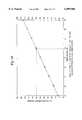
- FIG. 6is a graphical representation of a relationship between maximum temperature of a cell under short-circuited conditions and normalized energy content of a cell, the graph providing ratios of energy content-to-contact surface area for adjacently disposed cells;
- FIGS. 7-9illustrate various cell configurations that exhibit productive ratios of energy content-to-contact surface area
- FIG. 10shows an embodiment of a multiple-cell energy storage device in which one of the cells is subject to a short-circuit condition
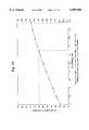
- FIG. 11illustrate a relationship between the maximum temperature in a cell stack as a function of the number of adjacent short-circuited cells at five difference state of charge (SOC) levels;
- FIG. 12illustrates a characteristic current waveform for an electrochemical cell upon occurrence of a short-circuit in the cell
- FIG. 13is an embodiment of an integrated short-circuit protection device in accordance with an embodiment of the present invention.
- FIG. 14is an exploded view of an energy storing module containing a number of interconnected thin-film electrochemical cells
- FIG. 15is a cross-sectional illustration of an embodiment of a pressure generating apparatus for maintaining a stack of electrochemical cells in a state of compression
- FIG. 16is an illustration of a band or strap including a tension producing clamp for use in a pressure generating apparatus for maintaining a stack of electrochemical cells in compression during charge and discharge cycling;
- FIG. 17is a perspective view of the tension producing clamp shown in FIG. 16.
- FIGS. 18-19illustrate in a graphical form a relationship between maximum cell temperature of an energy storing module and the energy content and thickness of the cell, respectively.
- the systemincludes solid-state, thin-film cells of the type shown in FIG. 1.
- Such thin-film electrochemical cellsare particularly well-suited for use in the construction of high-current, high-voltage energy storing modules and batteries, such as those used to power electric vehicles for example.
- FIG. 1Athere is shown an embodiment of a prismatic electrochemical cell 50 which includes an anode contact 56 and a cathode contact 55 formed respectively along opposing edges of the electrochemical cell 50.
- a thermal conductor 52is spot welded or otherwise attached to each of the anode and cathode contacts 56, 55, respectively.
- the thermal conductor 52is typically disposed along the length of the anode contact 56 and the cathode contact 55, and typically includes an electrical connection lead 54 for conducting current into and out of the electrochemical cell 50, the current being collected and conducted preferentially along the anode and cathode contacts 56, 55.
- the embodiment of a thermal conductor 63 shown in FIG. 1Bincludes a copper tab 53 that extends along the length of a sprayed metal anode or cathode contact 61.
- the copper tab 53includes a resilient member 59 through which heat is transferred between the cell 50 and an adjacently disposed heat sink, such as a wall of a metallic housing.
- the copper tab 53is spot welded to the sprayed metal contact 61 at a number of weld locations 51.
- a flexible electrical lead 57is ultrasonically welded to the end 63 of the copper tab 53. Current is conducted primarily along the sprayed metal contact 61 of the cell 50 and communicated to external connections via the flexible electrical leads 57.
- the thermal conductor 63provides a thermal flux path for transferring thermal energy between the electrochemical cells and a thermally conductive, electrically resistive material or element.
- a thermally conductive, electrically resistive material, element or structure as described hereinrefers to a surface coating/treatment or separate material that permits a sufficient amount of heat to be conducted therethrough, yet is electrically resistive to the flow of current relative to a current path provided for conducting current into and out of an electrochemical cell.
- An anodized coatingfor example, may have a thickness that permits a sufficient amount of thermal energy to be conducted therethrough, yet is sufficiently resistive to electrical current relative to the anode and cathode contacts of the cell or the thermal conductor.
- a thermally conductive polymer elementmay be employed, with the density of thermally conductive particles impregnated therein being selected to provide a desired balance between thermal and electrical conductivity characteristics.
- the thermal conductors 63also provide a thermal flux path for transferring heat between neighboring cells. If a short develops in a cell 73 within a stack of cells, for example, the excess heat, Q gen , generated by the short-circuited cell 73 is conducted through the thermally conductive, electrically resistive material provided on the housing surface 77, and to adjacent cells 72 and non-adjacent neighboring cells 71 via the thermal conductors 63. The excess heat, Q gen , is also conducted to adjacent cells 72 in physical contact with the short-circuited cell 73.
- a thermally conductive plate 75serves as a heat sink for a cell 74 situated at the end of the cell stack.
- the thermal conductor 63is configured so as to exhibit a spring-like character which provides for substantially continuous contact between a cell 73 and a structure, such as a metallic planar surface 77, disposed adjacent the cell 73 in response to relative movement between the cell 73 and the adjacent structure 77.
- a separate spring element, 69such as a tubular elastomeric element, may be retained within the thermal conductor 63 to enhance the spring properties of the thermal conductor 63.
- the thermal conductor 63may be fashioned from copper and have a substantially C-shaped, double C-shaped, Z-shaped, O-shaped, S-shaped, V-shaped, or finger-shaped cross-section. Other useful thermal conductors are disclosed in co-pending patent application Ser. No. 08/900,428 entitled "Thermal Conductor for High-Energy Electrochemical Cells" (Hoffman et al.), the contents of which are incorporated herein by reference.
- the electrochemical cell 50is fabricated to have a length L of approximately 135 mm, a height H of approximately 149 mm, and a width W ec of approximately 5.4mm or approximately 5.86 mm when including a foam core element.
- the width W c of the cathode contact 55 and the anode contact 56is approximately 3.72 mm, respectively.
- Such a cell 50typically exhibits a nominal energy rating of approximately 36.5 Wh, a peak power rating of 87.0 W at 80 percent depth of discharge (DOD), and a cell capacity of 14.4 Ah at full charge.
- FIG. 2illustrates in graphical form a relationship between voltage and capacity for an electrochemical cell having a construction substantially similar to that shown in FIG. 1A. It can be seen that an individual electrochemical cell has a nominal operating voltage ranging between approximately 2.0 V and 3.1 V.
- the electrochemical cells shown in FIGS. 1A-1Cmay have a construction similar to that illustrated in FIG. 3.
- an electrochemical cell 60is shown as having a flat wound prismatic configuration which incorporates a solid polymer electrolyte 66 constituting an ion transporting membrane, a lithium metal anode 64, a vanadium oxide cathode 68, and a cathode current collector 70.
- These film elementsare fabricated to form a thin-film laminated prismatic structure, which may also include an insulation film, such as polypropylene film.
- the cell shown in FIG. 3includes a central cathode current collector 70 which is disposed between each of the two cathode films 68 to form a bi-face cell configuration.
- a mono-face cell configurationmay alternatively be employed in which a single cathode collector 70 is associated with a single anode/electrolyte/cathode element combination.
- an insulating filmis typically disposed between individual anode/electrolyte/cathode/collector element combinations.
- a known sputtering metallization processis employed to form current collecting contacts along the edges 65, 79 of the anode and cathode current collecting films 64, 70, respectively. It is noted that the metal-sprayed contacts provide for superior current collection along the length of the anode and cathode film edges 65, 79, and demonstrate good electrical contact and heat transfer characteristics.
- the electrochemical cells illustrated in FIGS. 1A-1C and 3may be fabricated in accordance with the methodologies disclosed in U.S. Pat. Nos. 5,423,110, 5,415,954, and 4,897,917.
- a number of electrochemical cellsmay be selectively interconnected in a parallel and/or series relationship to achieve a desired voltage and current rating.
- a number of individual electrochemical cells 80may be grouped together and connected in parallel to common positive and negative power buses or lines to form a cell pack 82.
- a number of the electrochemical cell packs 82may then be connected in series to form a module 84.
- a number of individual modules 84may be connected in series to constitute a battery 86.
- FIG. 4depicts an arrangement of electrochemical cells 80 in accordance with a modular packaging approach which provides an efficient means of achieving desired power requirements for a broad range of high-power applications.
- eight electrochemical cells 80are grouped together and connected in parallel to form a cell pack 82.
- a module 84is constituted by grouping six cell packs 82 together and connecting the packs 82 in series.
- a battery 86is shown as constituting 24 modules 84 connected in series.
- each of the electrochemical cells 80has dimensions and characteristics equivalent to those of the cell depicted in FIG. 1, each individual cell 80 provides for a total energy output of approximately 36.5 Wh.
- Each cell pack 82provides for a total energy output of approximately 292 Wh, while each module 84 provides for a total energy output of 1.75 kWh.
- the battery 86constituted by an array of four axially and six longitudinally oriented modules 84 connected in series, provides for a total energy output of approximately 42 kWh. It is understood that the arrangement of electrochemical cells 80 and interconnection of cells 80 forming a cell pack 82, module 84, and battery 86, may vary from the arrangements depicted in FIG. 4.
- FIG. 5there is shown a number of electrochemical cells arranged in a stack configuration.
- a particular cell 112is depicted as having sustained a short-circuit.
- the cell 112generates heat as a consequence of the high rate of energy discharge resulting from the short-circuit.
- the thermal energy generated by the short-circuit in the cell 112is partially conducted through the cell 112 and to the outer surfaces 115, 117 of the cell 112.
- the close proximity of an adjacent cell 110to the short-circuited cell 112permits the thermal energy conducted to the outer surfaces 115, 117 of the cell 112 to dissipate into the adjacent cell 110.
- an adjacent cell 114having an outer surface 113 in thermal contact with an outer surface 117 of the cell 112, conducts heat produced by the cell 112 through the thermal contact interface 113, 117.
- the adjacent cells 110, 114include outer surfaces 111, 113 which are in intimate thermal contact with the outer surfaces 115, 117 of the cell 112.
- an insert elementsuch as a foam or metallic flat spring element, or thermally conductive material, may be situated between adjacent cells.
- the heat generated by the short-circuited cell 112is also conducted in they and z directions and, in particular, to adjacent and neighboring cells via the thermal conductors and thermally conductive, electrically resistive material as is depicted in FIG. 1C.
- the energy increase within the short-circuited cell 112, and the rate at which the energy generated from the short-circuit event is dissipated into adjacent cells 110, 114can be characterized through use of Fourier's Law of Heat Conduction.
- a brief discussion of a generalized one-dimensional heat conduction analysismay be useful. It is understood that the following description is provided for purposes of illustration only, and ignores three-dimensional transient heat transfer considerations.
- the rate at which heat flows axially through the short-circuited cell 112is denoted as Q gen , which represents the heat generated per unit time in the cell 112 of thickness dx.
- Q genrepresents the heat generated per unit time in the cell 112 of thickness dx.
- the quantity Q genrepresents the heat energy generated throughout the volume element 118 which is dependent on the rate of heat generation per unit volume per unit time, represented by the parameter q, and the volume of the element 118.
- the resulting energy balance equationis given by:
- Q x , Q x+dx , and Q genrepresent heat flow rates measured in watts (W)
- qrepresents the rate of heat generation per unit volume per unit time measured in watts/m 3
- dxrepresents the thickness of the volume element 118
- Arepresents the cross-sectional area of the volume element 118.
- a temperature increase within the energy storage system shown in FIG. 5 due to a short-circuit eventcan be appropriately managed by understanding the thermal characteristics and energy producing capability of the cells.
- An in-situ thermal management system in accordance with the principles of the present inventionmay be employed to dissipate excess thermal energy resulting from a short-circuit event without necessity of an external active thermal management scheme, such as a forced cooling or forced convection apparatus.
- the in-situ thermal management methodology described hereinmay be implemented by understanding the heat capacity and heat dissipation characteristics of the particular cells used in an energy storage system, and appropriately limiting the energy content of the cells.
- An important consideration that impacts the design of a multiple-cell energy storage systemconcerns the temperature at which the materials of a particular cell technology break down or degrade such that overall cell performance is significantly reduced.
- a cell having a construction of the type shown in FIGS. 1A-1C and 3has a breakdown temperature of approximately 180° C., which represents the melting point of lithium.
- Employment of an in-situ thermal management scheme implemented in accordance with the principles of the present inventionprevents the temperature of a cell from reaching a breakdown temperature, or a safety temperature lower than the breakdown temperature, even under short-circuit conditions.
- the heat dissipation characteristics of a particular cellare dependent on a number of factors, including the cell's technology, dimensions, and thermal/electrical properties. Taking into consideration these known factors, the heat dissipation characteristics of a cell may be altered and optimized. Since heat dissipation in the cell 112 is a function of thermal contact surface area with respect to contact surfaces of adjacent cells 110, 114, the maximum energy content per unit contact surface area required to maintain the cell temperature below a breakdown or safety temperature may be determined. By way of example, and with reference to FIG. 6, there is shown in graphical form a relationship between the maximum temperature of a cell having a construction as shown in FIGS.
- the energy content of a cell and the physical dimensions of the cellmay be selected so that the ratio of energy content-to-cell surface area is kept within a range such that the maximum cell temperature remains below a breakdown or safety temperature, even under short-circuit conditions.
- An energy content-to-contact surface area ratio of less than approximately 0.0050 Wh/cm 2 for a thin-film lithium polymer cellwill ensure that a worst-case temperature resulting from a short-circuit in the cell does not exceed the melting point of the lithium elements within the cell (i.e., 180° C.).
- the energy content and contact surface area of the cellmay be appropriately selected using the graph of FIG. 6. It is understood that graphs similar to that shown in FIG. 6 which characterize maximum cell temperature under short-circuit conditions relative to the ratio of energy content-to-contact surface area may be developed for energy storage cells constructed using technologies other than those described herein. It is noted that FIG. 18, for example, depicts a relationship between energy content and maximum cell temperature for a cell having a similar construction as that shown in FIGS. 1A-1C and 3 but a different cathode oxide.
- FIGS. 7-9The depictions of energy storage cells shown in FIGS. 7-9 are provided to illustrate that an in-situ thermal management design approach may be employed for energy storage cells having varying configurations.
- the length (L), height (H), width (w), or radius (r)may be varied as needed for a given application, with the constraint that the ratio of energy content-to-contact surface area remain in a range that prevents the worst-case cell temperature from exceeding the cell breakdown temperature.
- Equation [3]mathematically characterizes the maximum cell temperature of a thin-filmed electrochemical cell, which does not include a foam core element, as a function of various operative parameters.
- the dimensions of the cell characterized in Equation [3]are given as 0.135 m ⁇ 0.149 m ⁇ 0.054 m.
- the maximum cell temperature for the cellis given by:
- T maxrepresents the maximum temperature reached by a short-circuited cell in a module (°C.)
- ⁇ cellrepresents the density of the cell (kg/m 3 )
- Cp cellrepresents the heat capacity of the cell (J/kgK)
- Qrepresents the energy content of one cell per unit volume (Wh/m 3 )
- kcellrepresents the conductivity of the cell in the cell-to-cell axial direction (W/mK)
- ⁇represents cell thickness in the cell-to-cell axial direction (mm)
- K/Lrepresents the conductance of the thermal conductor (W/m 2 K).
- Equation [3] abovea relationship between maximum temperature of a short-circuited cell as a function of the cell's energy content for a given cell chemistry and configuration may be developed.
- a relationship between maximum cell temperature as a function of cell thicknessmay also be developed.
- FIGS. 18-19there is depicted a relationship between maximum cell temperature as a function of energy content and cell thickness, respectively.
- a thin-film electrochemical cell of the type characterized aboveshould have an energy content which is limited to less than approximately 38 Wh to ensure that the maximum temperature of the cell will not exceed a breakdown temperature, such as the melting point of lithium (i.e., 180° C.). It is interesting to note the linearity of the maximum cell temperature-to-energy content relationship depicted in FIGS. 18 and 6, given the difference in cell technology. It can be seen from FIG. 19 that the thickness of the cell should not exceed approximately 8.5 mm in order to ensure that the maximum temperature of the cell does not exceed the 180° C. breakdown temperature.
- Equation [4]characterizes maximum cell temperature for an energy storing module of the same cell technology as that implicated in Equation [3] in which some of the cells include a foam core element compressed to approximately 2 mm. More specifically, Equation [4] characterizes maximum cell temperature for a module design in which compressed foam core elements are provided in every two electrochemical cells. In this case, maximum cell temperature for such a module configuration is given by:
- Equations [3] and [4]differ only by constants (i.e., the constants 1/1.1 and 1/1.2 in Equation [3]).
- Equation [5]characterizes the maximum cell temperature for a module having cells of the same technology implicated in Equations [3]-[4], wherein the cells incorporate a foam core element that is thinner than the element associated with Equation [4] above. More specifically, Equation [5] below assumes that a foam core element having a thickness of approximately 1/32 inches is provided in every two cells of the cell stack. The foam core element is fabricated from Poron S2000. The maximum cell temperature for a module having this configuration is given by:
- Equations [3]-[5]may be used to quantify the effect of heat capacity of the components within the cell on the maximum cell temperature, T max , reached during a short-circuit event. These equations, therefore, may be used to characterize maximum cell temperatures under similar situations for energy storing cells of differing technologies.
- Equations [3]-[5]were directed to the investigation of electrochemical cells having an energy content that varied from approximately 30 to 40 Wh, a cell thickness, 6,that varies from approximately 5.4 and 7.8 mm, and cells that utilize a thermal conductor having a conductance value, K/L, that varies between approximately 200 and 600 W/m 2 K.
- the in-situ thermal management approach described above with reference to FIGS. 1C and 5is generally applicable for managing short-circuit temperature increases occurring in a single cell of a grouping of cells.
- an enhanced in-situ short-circuit protection schememay be implemented to prevent thermal runaway within the cell stack, and to isolate a particular cell from the parallel connection upon occurrence of a short-circuit in the cell.
- the energy storage device 120includes eight energy storage cells respectively connected in parallel to common positive and negative terminals 124, 125.
- the cell EC1is shown as a short-circuit. Given this arrangement, and with reference to FIG. 11, it can be seen that only one short-circuited cell within a stack of eight cells can be managed using the above-described in-situ thermal management methodology without exceeding the breakdown temperature of the cell material.
- An in-situ short-circuit protection devicemay be incorporated into an energy storage system to prevent multiple short-circuit events from occurring.
- a fuse 123is connected in series with a respective cell 122 within the multiple-cell energy storage device 120.
- the fuse 123 of the defective cell 122blows so as to electrically isolate the short-circuited cell 122 from the parallel connection.
- the heat generated during development of the short-circuit in the cell 122 and after blowing of the fuse 123is conducted to cells adjacent the defective cell 122 in a manner previously described.
- the maximum temperature attainable by a cell under worst-case conditionsis well below the breakdown temperature of the cell. More particularly, the data of FIG. 11 confirms that the temperature of a short-circuited cell within the cell stack never exceeds a safety temperature of 130° C. when an in-situ short-circuit protection device is employed.
- FIG. 12there is illustrated a graph which characterizes the effect on cell current upon the occurrence of a short-circuit in a thin-film electrochemical cell.
- the current in the cell characterized in FIG. 12spikes at a value in excess of 500 A in less than approximately 100 milliseconds. Following the current spike, the current in the cell rapidly decays to approximately 150 A after 1 second, and gradually decays thereafter. At 5 seconds following the short-circuit event, the cell current reaches a value of approximately 60 A.
- each of the fuses 123 connected in series with a corresponding energy storage cell 122are designed to activate in response to a current spike generated from a short-circuit in the cell 122.
- a fuse 123typically has a current rating that prevents the fuse from activating during normal operation, yet permits the fuse to activate in response to a short-circuit condition. Exploiting the current spike as a triggering mechanism for the fuse 123 provides for a large current gap between the maximum operating current level of the cell 122 and the minimum activation current level of the fuse 123.
- the parallel connected cells of an energy storage devicehave a structure and behavior similar to those previously described with reference to FIGS. 1A-1C and 3.
- the fuses connected in series with the cellshave a current rating of approximately 50 A.
- protection against accidental shorting of an energy storage device or cellmay be of primary concern. It may be desirable, therefore, to employ a fuse that is activated more slowly than the fast acting fuse described above. For example, a fuse that activates after several hundred milliseconds or several seconds after occurrence of a short-circuit in the cell may be employed. Although excess heat is generated between the time the short occurs and the time the fuse blows, the in-situ thermal management methodology described previously provides for the safe dissipation of such excess heat.
- FIG. 13there is illustrated an embodiment of a short-circuit protection device fabricated in an integrated package.
- the integrated device 130includes an enclosure 132 within which eight fuses (not shown) are mounted. A first contact of each fuse is connected in series with a corresponding one of eight terminals 134, and a second contact of the each fuse is connected to a common bus 140.
- Each of the terminals 134includes a lead 136 and a contact 138.
- the common bus 140is typically coupled to one or more common busses of other short-circuit protection devices 130 connected to corresponding cell arrays to form a series connected energy storage device, such as a module.
- the enclosure 132has a height, H E , of 16.00 mm, a width, W E , of 7.49 mm, and a length, L E , of 50.80 mm.
- the lead portion 136 of the terminal 134has a height, H L , of 12.70 mm, a width, W L , of 1.27 mm, and a length, L L , of 5.00 mm.
- the contact portion 138 of the terminal 134has a height, H C , and a width, W C , of 1.27 mm, and a length, L C , of 13.03 mm.
- the common bus 140has a height, H CB , of 6.35 mm, a width, W CB , of 1.27 mm, and a length, L CB , of 49.02 mm.
- FIG. 14there is shown an exploded view of an embodiment of an energy storing module 142 which houses a number of electrochemical cells 144, interconnection hardware, and control hardware and software.
- the module 142includes a stack of 48 electrochemical cells 144 which are interconnected through use of a interconnect board 147.
- Short-circuit protection circuitrysuch as an integrated short-circuit protection pack 148, is typically provided on the interconnect board 147.
- Each of the six integrated short-circuit protection packs 148 disposed on the interconnect board 147electrically couple to a corresponding one of six cell packs 143 upon mounting the interconnect board 147 in place above the stack of cells 144.
- the volume of an electrochemical cell of the type described previously with regard to FIG. 1varies during charge and discharge cycling due to the migration of lithium ions into and out of the lattice structure of the cathode material. This migration creates a corresponding increase and decrease in total cell volume on the order of approximately five to six percent during charging and discharging, respectively.
- a pressure producing apparatusis employed to maintain the cells in a continuous state of compression to ensure continuous intimate contact between cell of the cell stack. It is considered desirable that the compressive forces, whether produced internally or externally of the cell, be distributed fairly uniformly over the surface of application.
- the stack of electrochemical cells 144 shown in FIG. 14are banded together by use of two bands 146 and two opposing thrust plates 145.
- the 48 electrochemical cells 144are subjected to continuous compressive forces generated by use of the bands 146/thrust plates 145 and a foam or spring-type element disposed in each of the cells 144 and/or between all or selected ones of the cells 144.
- the foam or spring-type core element provided in the center of each of the cells 144serves to distribute pressure evenly between the cells 144, which is of particular importance as cell volumes change during charge and discharge cycling.
- a metal strap 194includes a wave-like spring 198 which generates tension forces that cause the thrust plates 194, in turn, to exert compressive forces on the cell stack 192.
- the tension spring apparatus illustrated in FIG. 15may be implemented using a number of coil springs or using elastomeric material, and that a combination of metallic and elastomeric spring materials may also be advantageously employed. Further, it will be appreciated that foam or other spring elements may be incorporated within the cell stack and/or within individual cells in combination with a tension spring apparatus external to cell stack.
- FIG. 16illustrates an embodiment of a strap apparatus 180 which is particularly useful in constraining a number of electrochemical cells configured as a stack or bundle.
- the strap apparatus shown in FIG. 16incorporates a unique clamp 182 which significantly enhances the efficacy of a cell stack pressure system.
- the strap apparatusincludes two bands 180 each having C-shaped ends 181.
- a clamp 182is attached to a band 180 by coupling the C-shaped ends 181 of the band 180 with corresponding C-shaped ends 184 of the clamp 182. It is assumed that the bands 180 are disposed around the stack of cells in a manner as shown in FIG. 15.
- the clamp 182includes a hinge 186 integral to the clamp 182 which is collapsible onto a contact surface 188 of the clamp 182 when subjected to sufficient force.
- the sign wave-shaped spring 189may be configured, in terms of shape, thickness, and material, to provide for a desired amount of expansion and retraction of the strap apparatus during charge/discharge cycling of the cells.
- Other useful pressure generating mechanismsare disclose in co-pending patent application Ser. No. 08/900,429 entitled “Pressure System and Method for Rechargeable Thin-Film Electrochemical Cells” (Hoffman et al.), the contents of which are incorporated herein by reference.
- a short-circuit protection devicemay include thermally activated fuses, such as Model NTE8090 manufactured by NTE Electronics, rather those described herein.
- Thermally activated fusestypically activate at a prescribed temperature, such as a temperature below a breakdown temperature.
- a thermally activated fusemay be connected in series with a current activated fuse which provides for increased activation reliability.
- the principles of the present inventionmay be employed for use with battery technologies other than those exploiting lithium polymer electrolytes, such as those employing nickel metal hydride (Ni-MH), lithium-ion, (Li-Ion), and other high energy battery technologies. Accordingly, the scope of the present invention should not be limited by the particular embodiments discussed above, but should be defined only by the claims set forth below and equivalents thereof.
Landscapes
- Chemical & Material Sciences (AREA)
- Chemical Kinetics & Catalysis (AREA)
- Electrochemistry (AREA)
- General Chemical & Material Sciences (AREA)
- Secondary Cells (AREA)
- Connection Of Batteries Or Terminals (AREA)
- Protection Of Static Devices (AREA)
Abstract
Description
TABLE 1 ______________________________________ Thermal Conductivity (W/m° C.) Direction of the Direction Specific film of the Density Heat Section thickness connectors (kg/m.sup.3) (J/kg° C.) ______________________________________ Active Section 0.4042 48.10 1356 1411 Anode Side, 0.0466 28.90 252 2714 Inactive Zone Cathode Side, 0.0388 18.45 441 1470 InactiveSide Complete Cell 1218 1435 Other Components ______________________________________ Density x Thermal Conductivity specific heat Component (W/m° C.) (kJ/m.sup.3 ° C.) ______________________________________ Cell's core (foam) 0.071 401.3 Metallization 366.7 3254.6 Spring-type 134.5 3254.6 conductor Vessel wall - 178.8 2566.9 anodized ______________________________________
Q.sub.x +Q.sub.gen =Q.sub.x+dx [ 1]
Q.sub.gen =qAdx [2]
T.sub.max =1/1.1·1/1.2·0.037738·(1/(ρ.sub.cell ·Cp.sub.cell)).sup.0.3856 ·(Q/kcell)·(δ).sup.0.6146 ·(K/L).sup.-0.077 [ 3]
T.sub.max =0.037738·(1/(ρ.sub.cell ·Cp.sub.cell)).sup.03856 ·(Q/kcell)·(δ).sup.0.6146 ·(K/L).sup.-0.077 [ 4]
T.sub.max =1/1.1·0.037738·(1/(ρ.sub.cell ·Cp.sub.cell)).sup.03856 ·(Q/kcell)·(δ).sup.0.6146 ·(K/L).sup.-0.077 [ 5]
Claims (20)
Priority Applications (7)
| Application Number | Priority Date | Filing Date | Title |
|---|---|---|---|
| US08/900,929US6099986A (en) | 1997-07-25 | 1997-07-25 | In-situ short circuit protection system and method for high-energy electrochemical cells |
| PCT/US1998/015299WO1999005747A1 (en) | 1997-07-25 | 1998-07-23 | In situ short-circuit protection system and method for high-energy electrochemical cells |
| CA 2297839CA2297839C (en) | 1997-07-25 | 1998-07-23 | In situ short-circuit protection system and method for high-energy electrochemical cells |
| EP19980935973EP1021850A1 (en) | 1997-07-25 | 1998-07-23 | In situ short-circuit protection system and method for high-energy electrochemical cells |
| AU85109/98AAU8510998A (en) | 1997-07-25 | 1998-07-23 | In situ short-circuit protection system and method for high-energy electro chemical cells |
| JP2000504628AJP4267812B2 (en) | 1997-07-25 | 1998-07-23 | Field short circuit protection system and method for high energy electrochemical cells |
| US09/586,218US6548206B1 (en) | 1997-07-25 | 2000-06-02 | In-situ short-circuit protection system and method for high-energy electrochemical cells |
Applications Claiming Priority (1)
| Application Number | Priority Date | Filing Date | Title |
|---|---|---|---|
| US08/900,929US6099986A (en) | 1997-07-25 | 1997-07-25 | In-situ short circuit protection system and method for high-energy electrochemical cells |
Related Child Applications (1)
| Application Number | Title | Priority Date | Filing Date |
|---|---|---|---|
| US09/586,218DivisionUS6548206B1 (en) | 1997-07-25 | 2000-06-02 | In-situ short-circuit protection system and method for high-energy electrochemical cells |
Publications (1)
| Publication Number | Publication Date |
|---|---|
| US6099986Atrue US6099986A (en) | 2000-08-08 |
Family
ID=25413313
Family Applications (2)
| Application Number | Title | Priority Date | Filing Date |
|---|---|---|---|
| US08/900,929Expired - LifetimeUS6099986A (en) | 1997-07-25 | 1997-07-25 | In-situ short circuit protection system and method for high-energy electrochemical cells |
| US09/586,218Expired - LifetimeUS6548206B1 (en) | 1997-07-25 | 2000-06-02 | In-situ short-circuit protection system and method for high-energy electrochemical cells |
Family Applications After (1)
| Application Number | Title | Priority Date | Filing Date |
|---|---|---|---|
| US09/586,218Expired - LifetimeUS6548206B1 (en) | 1997-07-25 | 2000-06-02 | In-situ short-circuit protection system and method for high-energy electrochemical cells |
Country Status (6)
| Country | Link |
|---|---|
| US (2) | US6099986A (en) |
| EP (1) | EP1021850A1 (en) |
| JP (1) | JP4267812B2 (en) |
| AU (1) | AU8510998A (en) |
| CA (1) | CA2297839C (en) |
| WO (1) | WO1999005747A1 (en) |
Cited By (42)
| Publication number | Priority date | Publication date | Assignee | Title |
|---|---|---|---|---|
| US6291972B1 (en)* | 1999-02-17 | 2001-09-18 | Chaojiong Zhang | System for battery formation, charging, discharging, and equalization |
| US6548206B1 (en)* | 1997-07-25 | 2003-04-15 | 3M Innovative Properties Company | In-situ short-circuit protection system and method for high-energy electrochemical cells |
| US20030165734A1 (en)* | 2002-03-01 | 2003-09-04 | Hinton Michael L. | Method and apparatus for cooling and positioning prismatic battery cells |
| US20040048152A1 (en)* | 1998-05-20 | 2004-03-11 | Shizukuni Yata | Non-aqueous secondary battery and its control method |
| US6753104B2 (en)* | 1998-06-02 | 2004-06-22 | Ngk Insulators, Ltd. | Lithium secondary battery |
| US20060251960A1 (en)* | 2005-04-20 | 2006-11-09 | Junill Yoon | Housing member for battery module |
| US20070126396A1 (en)* | 2005-12-02 | 2007-06-07 | Lg Chem, Ltd. | Battery module of high cooling efficiency |
| US20090186265A1 (en)* | 2008-01-18 | 2009-07-23 | Lg Chem, Ltd | Battery cell assembly and method for assembling the battery cell assembly |
| US20090208831A1 (en)* | 2008-02-20 | 2009-08-20 | Sumitomo Chemical Company, Limited | Device having electrode group |
| US20090325055A1 (en)* | 2008-06-30 | 2009-12-31 | Lg Chem, Ltd. | Battery module having cooling manifold with ported screws and method for cooling the battery module |
| US20090325052A1 (en)* | 2008-06-30 | 2009-12-31 | Lg Chem, Ltd. | Battery Module Having Cooling Manifold and Method for Cooling Battery Module |
| US20090325059A1 (en)* | 2008-06-30 | 2009-12-31 | Lg Chem, Ltd. | Battery Module Having Battery Cell Assemblies With Alignment-Coupling Features |
| US20100104935A1 (en)* | 2008-10-28 | 2010-04-29 | Weston Arthur Hermann | Heat dissipation for large battery packs |
| US20100247999A1 (en)* | 2009-01-12 | 2010-09-30 | A123 Systems, Inc. | Prismatic Battery Module with Scalable Architecture |
| US20100266883A1 (en)* | 2009-04-20 | 2010-10-21 | Lg Chem, Ltd. | Frame member, frame assembly and battery cell assembly made therefrom and methods of making the same |
| US20100279153A1 (en)* | 2009-04-30 | 2010-11-04 | Lg Chem, Ltd. | Battery systems, battery module, and method for cooling the battery module |
| US20100279152A1 (en)* | 2009-04-30 | 2010-11-04 | Lg Chem, Ltd. | Battery systems, battery modules, and method for cooling a battery module |
| US20100279154A1 (en)* | 2009-04-30 | 2010-11-04 | Lg Chem, Ltd. | Battery systems, battery modules, and method for cooling a battery module |
| US20110189527A1 (en)* | 2008-09-30 | 2011-08-04 | Magna E-Car Systems Gmbh & Co Og | Energy accumulator module |
| WO2012009803A1 (en)* | 2010-07-22 | 2012-01-26 | Bathium Canada Inc | Current collecting terminal for electrochemical cells |
| EP2416405A1 (en)* | 2010-08-04 | 2012-02-08 | Tesla Motors, Inc. | Battery pack with cell-level fusing and method of using same |
| US8133608B2 (en) | 2010-08-04 | 2012-03-13 | Tesla Motors, Inc. | Battery pack with cell-level fusing |
| US8288031B1 (en) | 2011-03-28 | 2012-10-16 | Lg Chem, Ltd. | Battery disconnect unit and method of assembling the battery disconnect unit |
| US8353315B2 (en) | 2010-08-23 | 2013-01-15 | Lg Chem, Ltd. | End cap |
| US8469404B2 (en) | 2010-08-23 | 2013-06-25 | Lg Chem, Ltd. | Connecting assembly |
| GB2504116A (en)* | 2012-07-19 | 2014-01-22 | Energy Control Ltd | Secondary Battery Pack |
| US8662153B2 (en) | 2010-10-04 | 2014-03-04 | Lg Chem, Ltd. | Battery cell assembly, heat exchanger, and method for manufacturing the heat exchanger |
| US8758922B2 (en) | 2010-08-23 | 2014-06-24 | Lg Chem, Ltd. | Battery system and manifold assembly with two manifold members removably coupled together |
| TWI462373B (en)* | 2012-06-28 | 2014-11-21 | Energy Control Ltd | Secure battery pack formed by a plurality of secondary batteries |
| US8920956B2 (en) | 2010-08-23 | 2014-12-30 | Lg Chem, Ltd. | Battery system and manifold assembly having a manifold member and a connecting fitting |
| US8932739B2 (en) | 2010-08-04 | 2015-01-13 | Tesla Motors, Inc. | Battery pack configuration to reduce hazards associated with internal short circuits |
| US9005799B2 (en) | 2010-08-25 | 2015-04-14 | Lg Chem, Ltd. | Battery module and methods for bonding cell terminals of battery cells together |
| US9065096B2 (en) | 2011-02-24 | 2015-06-23 | Samsung Sdi Co., Ltd. | Fuel cell stack |
| US9147916B2 (en) | 2010-04-17 | 2015-09-29 | Lg Chem, Ltd. | Battery cell assemblies |
| US9178192B2 (en) | 2011-05-13 | 2015-11-03 | Lg Chem, Ltd. | Battery module and method for manufacturing the battery module |
| US9287726B2 (en)* | 2013-11-06 | 2016-03-15 | The Boeing Company | Virtual cell for battery thermal management |
| WO2016066002A1 (en)* | 2014-10-27 | 2016-05-06 | 深圳市快车道新能源发展有限公司 | Connecting method of battery combined system |
| US9496544B2 (en) | 2011-07-28 | 2016-11-15 | Lg Chem. Ltd. | Battery modules having interconnect members with vibration dampening portions |
| JP2017103123A (en)* | 2015-12-02 | 2017-06-08 | トヨタ自動車株式会社 | Stacked all-solid battery |
| US9954215B2 (en) | 2009-12-04 | 2018-04-24 | A123 Systems, LLC | Battery with integrated power management system and scalable battery cutoff |
| US20220309210A1 (en)* | 2021-03-24 | 2022-09-29 | The Boeing Company | Systems and methods for multi-conditional battery configuration |
| US11695152B2 (en) | 2019-03-22 | 2023-07-04 | Toyota Jidosha Kabushiki Kaisha | Case and method for manufacturing the same, method for inserting stacked body, and cell stack |
Families Citing this family (8)
| Publication number | Priority date | Publication date | Assignee | Title |
|---|---|---|---|---|
| DE102005042169B4 (en)* | 2005-09-06 | 2014-04-03 | Dilo Trading Ag | Using an array of lithium polymer batteries |
| JPWO2011151981A1 (en) | 2010-06-02 | 2013-07-25 | パナソニック株式会社 | Battery module |
| JP2012182890A (en)* | 2011-02-28 | 2012-09-20 | Sharp Corp | Protective device for secondary battery, secondary battery device, and secondary battery |
| US8649140B2 (en) | 2011-03-04 | 2014-02-11 | Electrochem Solutions, Inc. | Voltage activated 2nd level safety circuit for permanent isolation |
| TWI449244B (en)* | 2012-08-22 | 2014-08-11 | Energy Control Ltd | Battery pack formed by connecting two secondary batteries with two fuses in parallel |
| US9991699B2 (en) | 2016-05-02 | 2018-06-05 | Microsoft Technology Licensing, Llc | Enablement of device power-on with proper assembly |
| JP7056142B2 (en)* | 2017-12-25 | 2022-04-19 | トヨタ自動車株式会社 | Battery module |
| GB2631942A (en)* | 2023-07-17 | 2025-01-22 | Solace Global Projects Ltd | Power and data hub for soldiers |
Citations (158)
| Publication number | Priority date | Publication date | Assignee | Title |
|---|---|---|---|---|
| US2812376A (en)* | 1952-03-07 | 1957-11-05 | Yardney International Corp | Electric battery |
| US3193412A (en)* | 1962-02-20 | 1965-07-06 | Electric Storage Battery Co | Electric battery |
| US3390014A (en)* | 1960-05-11 | 1968-06-25 | Eisler Paul | Secondary electric batteries having plurality of thin flexible intermediate bipolar plates |
| US3578506A (en)* | 1968-02-29 | 1971-05-11 | Accumulateurs Fixes | Sealing arrangement for terminals of electrochemical generators |
| US3630783A (en)* | 1970-05-11 | 1971-12-28 | Mallory Battery Canada | Heat-shrinkable packaging for batteries |
| US3786466A (en)* | 1971-03-19 | 1974-01-15 | Hitachi Ltd | Electrical leakage detecting device |
| US3793501A (en)* | 1972-12-04 | 1974-02-19 | Ici America Inc | Explosive switch |
| US3899355A (en)* | 1974-02-14 | 1975-08-12 | Polaroid Corp | Battery assembly |
| US3937635A (en)* | 1975-01-09 | 1976-02-10 | Wilson Greatbatch | Lithium-iodine battery |
| US4028479A (en)* | 1974-12-26 | 1977-06-07 | Polaroid Corporation | Flat battery |
| US4060669A (en)* | 1975-09-10 | 1977-11-29 | Polaroid Corporation | Flat battery |
| US4060670A (en)* | 1972-11-10 | 1977-11-29 | Pentti Juuse Tamminen | Alkaline flat cell battery |
| US4080728A (en)* | 1974-08-08 | 1978-03-28 | Polaroid Corporation | Method of making flat battery |
| US4091186A (en)* | 1977-11-07 | 1978-05-23 | Esb Incorporated | Dry cell battery having electrical spring contact adhered to terminal |
| US4098965A (en)* | 1977-01-24 | 1978-07-04 | Polaroid Corporation | Flat batteries and method of making the same |
| US4105807A (en)* | 1975-07-28 | 1978-08-08 | Unican Electrochemical Products Ltd. | Production of thin, stable, solid electrolyte films of high ionic conductivity |
| US4150266A (en)* | 1977-01-27 | 1979-04-17 | Networks Electronic Corp. | Miniature pyrotechnic squib switch, single pole, normally open |
| US4152825A (en)* | 1974-06-10 | 1979-05-08 | Polaroid Corporation | Method of making a flat battery |
| US4207389A (en)* | 1977-11-25 | 1980-06-10 | P. R. Mallory & Co. Inc. | Solid state cells |
| US4209479A (en)* | 1977-11-25 | 1980-06-24 | P. R. Mallory & Co. Inc. | Means for improving manufacture of solid state cells |
| US4233371A (en)* | 1978-09-13 | 1980-11-11 | Electrochemische Energieconversie N.V. | Method for the manufacture of an electrochemical cell or battery and battery made by the method |
| US4238721A (en)* | 1979-02-06 | 1980-12-09 | The United States Of America As Represented By The United States Department Of Energy | System and method for charging electrochemical cells in series |
| US4241152A (en)* | 1978-11-14 | 1980-12-23 | Deutsch Automobilgesellschaft Mbh | Disconnectable gas-tight and pressure-resistant electrical lead-out |
| GB1582979A (en) | 1976-07-24 | 1981-01-21 | Celaya Emparanza Galdos Sa | Electric batteries |
| US4303877A (en)* | 1978-05-05 | 1981-12-01 | Brown, Boveri & Cie Aktiengesellschaft | Circuit for protecting storage cells |
| US4321435A (en)* | 1972-07-13 | 1982-03-23 | Siemens Aktiengesellschaft | Fluid actuating device for an electric circuit breaker |
| US4322484A (en)* | 1978-09-05 | 1982-03-30 | General Electric Company | Spiral wound electrochemical cell having high capacity |
| US4342978A (en)* | 1979-03-19 | 1982-08-03 | S&C Electric Company | Explosively-actuated switch and current limiting, high voltage fuse using same |
| US4370531A (en)* | 1980-09-19 | 1983-01-25 | S&C Electric Company | Electric switch and improved device using same |
| US4383013A (en)* | 1980-07-23 | 1983-05-10 | Chloride Silent Power Limited | High temperature multicell electrochemical storage batteries |
| US4409538A (en)* | 1980-08-27 | 1983-10-11 | Kabushiki Kaisha Daini Seikosha | Charge control circuit |
| US4409086A (en)* | 1980-03-26 | 1983-10-11 | Metallgesellschaft Aktiengesellschaft | Electrolytic cell |
| US4429026A (en)* | 1982-01-20 | 1984-01-31 | Polaroid Corporation | Laminar multicell lithium batteries |
| US4436792A (en)* | 1981-11-12 | 1984-03-13 | Nippon Kogaku K.K. | Container device for planar battery |
| US4477545A (en)* | 1983-06-29 | 1984-10-16 | Union Carbide Corporation | Isostatic compression method for producing solid state electrochemical cells |
| US4479083A (en)* | 1982-09-30 | 1984-10-23 | Vanner, Inc. | DC Power system having battery voltage equalizer circuit |
| US4490707A (en)* | 1980-08-18 | 1984-12-25 | S&C Electric Company | Explosively-actuated, multi-gap high voltage switch |
| US4495259A (en)* | 1983-02-11 | 1985-01-22 | The Gates Rubber Company | Vibration resistant battery |
| US4507857A (en)* | 1983-06-22 | 1985-04-02 | Battery Engineering Inc. | Electrochemical cell |
| US4517265A (en)* | 1982-06-30 | 1985-05-14 | Hydro-Quebec | Composite and flexible anodes for lithium cells in non-aqueous medium |
| US4518665A (en)* | 1982-10-20 | 1985-05-21 | Hitachi, Ltd. | Sheet-shaped polymer secondary battery of layer built type |
| US4525439A (en)* | 1983-10-07 | 1985-06-25 | Simonton Robert D | Connector aperture seal for a galvanic cell |
| FR2511547B1 (en) | 1981-08-13 | 1985-08-09 | Moli Energy Ltd | METHOD FOR INCREASING THE REVERSIBILITY OF AN ELECTRIC BATTERY, ELECTRODE DEVICE FOR CARRYING OUT SAID METHOD AND BATTERY THUS OBTAINED |
| US4547438A (en)* | 1984-12-18 | 1985-10-15 | Duracell Inc. | Battery assembly |
| US4571468A (en)* | 1982-07-16 | 1986-02-18 | University Of Texas System | Inductive store opening switch |
| US4654278A (en)* | 1983-09-29 | 1987-03-31 | The United States Of America As Represented By The Secretary Of The Navy | Thermal cell non-deflagration design |
| US4664993A (en)* | 1981-08-24 | 1987-05-12 | Polaroid Corporation | Laminar batteries and methods of making the same |
| US4670703A (en)* | 1985-05-06 | 1987-06-02 | General Electric Company | Battery charger with three different charging rates |
| US4691085A (en)* | 1985-12-19 | 1987-09-01 | S&C Electric Company | High voltage interrupting switch with improved contact connection arrangement and method |
| US4692577A (en)* | 1985-10-25 | 1987-09-08 | S&C Electric Company | Switch for a high-voltage interrupting module |
| US4707795A (en)* | 1983-03-14 | 1987-11-17 | Alber Engineering, Inc. | Battery testing and monitoring system |
| US4752540A (en)* | 1987-06-05 | 1988-06-21 | Honeywell Inc. | Polymeric enclosures for non-aqueous active metal cells |
| US4758483A (en)* | 1983-03-11 | 1988-07-19 | Societe Nationale Elf Aquitaine | Novel macromolecular material for use in realizing electrolytes and/or electrodes |
| US4816354A (en)* | 1988-03-09 | 1989-03-28 | Tamminen Pentti J | Alkaline cell battery and method for manufacture thereof |
| US4824746A (en)* | 1987-03-11 | 1989-04-25 | Hydro-Quebec | Thin electrode supported on electronically conductive sheet and process of manufacture |
| US4828939A (en)* | 1987-06-01 | 1989-05-09 | Eltech Systems Corporation | Bipolar metal/air battery |
| US4851307A (en)* | 1986-10-30 | 1989-07-25 | Societe Nationale Elf Aquitaine | Ionically conductive material |
| US4852684A (en)* | 1987-12-16 | 1989-08-01 | Minnesota Mining And Manufacturing Company | Compressible ear tip |
| US4883726A (en)* | 1986-05-23 | 1989-11-28 | Emanuel Peled | Multi-cell battery |
| US4887348A (en)* | 1988-03-09 | 1989-12-19 | Tamminen Pentti J | Alkalline cell battery and method for manufacture thereof |
| US4897917A (en)* | 1987-06-18 | 1990-02-06 | Societe Nationale Elf Aquitaine | Method of assembling components of an electrochemical generator using thin films of lithium |
| US4911993A (en)* | 1988-02-01 | 1990-03-27 | Eltech Systems Corporation | Bipolar, filter-press, consumable metal anode battery |
| US4913259A (en)* | 1987-12-16 | 1990-04-03 | Minnesota Mining And Manufacturing Company | Compressible ear tip |
| US4923582A (en)* | 1982-12-27 | 1990-05-08 | Eltech Systems Corporation | Monopolar, bipolar and/or hybrid memberane cell |
| US4927717A (en)* | 1987-06-01 | 1990-05-22 | Eltech Systems Corporation | Bipolar metal/air battery |
| US4961043A (en)* | 1988-03-15 | 1990-10-02 | Norand Corporation | Battery conditioning system having communication with battery parameter memory means in conjunction with battery conditioning |
| GB2206726B (en) | 1987-07-03 | 1990-10-24 | Chloride Silent Power Ltd | Batteries |
| US4967136A (en)* | 1989-09-25 | 1990-10-30 | Prestolite Electric Incorporated | Battery equalization circuit for a dual voltage charging system |
| US4971531A (en)* | 1988-10-28 | 1990-11-20 | Ab Nike | Pump arrangement driven by compressed-air |
| US4973936A (en)* | 1989-04-27 | 1990-11-27 | The United States Of America As Represented By The Administrator Of The National Aeronautics And Space Adminstration | Thermal switch disc for short circuit protection of batteries |
| US4997732A (en)* | 1989-03-30 | 1991-03-05 | Mhb Joint Venture | Battery in a vacuum sealed enveloping material and a process for making the same |
| US5008161A (en)* | 1989-02-01 | 1991-04-16 | Johnston Lowell E | Battery assembly |
| US5057385A (en)* | 1990-12-14 | 1991-10-15 | Hope Henry F | Battery packaging construction |
| US5066555A (en)* | 1981-04-27 | 1991-11-19 | Sporax Oy | Contact arrangement for a galvanic battery |
| US5070427A (en)* | 1990-01-31 | 1991-12-03 | Sparton Corporation | Thermal switch for battery protection |
| US5070787A (en)* | 1988-06-24 | 1991-12-10 | The Board Of Regents Of The University Of Texas System | Method and apparatus for switching an electrical circuit |
| US5071652A (en)* | 1990-12-11 | 1991-12-10 | Globe-Union Inc. | Metal oxide hydrogen battery having improved heat transfer properties |
| US5089027A (en)* | 1990-11-26 | 1992-02-18 | Gould Inc. | Method for producing a solid electrolyte cell |
| US5162171A (en)* | 1991-10-28 | 1992-11-10 | Globe-Union Inc. | Metal oxide-hydrogen battery having modules extending longitudinally of the pressure vessel |
| US5180641A (en)* | 1991-05-09 | 1993-01-19 | Rockwell International Corporation | Battery cell bypass circuit |
| US5197889A (en)* | 1992-02-03 | 1993-03-30 | Motorola, Inc. | Electrical contact for battery package or similar device |
| US5199239A (en)* | 1991-09-30 | 1993-04-06 | Honeywell Inc. | Housing seal interface |
| US5204194A (en)* | 1992-05-21 | 1993-04-20 | Magnavox Electronic Systems Company | Multicell battery having a tab-fuse for overcurrent interruption |
| US5227264A (en)* | 1991-02-14 | 1993-07-13 | Hydro-Quebec | Device for packaging a lithium battery |
| US5227259A (en)* | 1991-07-24 | 1993-07-13 | Electric Power Research Institute, Inc. | Apparatus and method for locating and isolating failed cells in a battery |
| US5283512A (en)* | 1992-04-13 | 1994-02-01 | Hughes Aircraft Company | Charge balancing of batteries during charging |
| US5300373A (en)* | 1992-09-11 | 1994-04-05 | Valence Technology, Inc. | Electrochemical cell stack and method of making an electrochemical cell stack |
| US5313152A (en)* | 1992-06-19 | 1994-05-17 | Ford Motor Company | Network for minimizing current imbalances in a faradaic battery |
| US5324597A (en)* | 1990-05-16 | 1994-06-28 | Silent Power Gmbh Fur Energiespeichertechnik | Thermal shunt for a battery |
| US5337042A (en)* | 1992-09-28 | 1994-08-09 | Chrysler Corporation | Vehicle communications network transceiver, transmitter circuit therefor |
| US5346786A (en)* | 1994-03-21 | 1994-09-13 | Hodgetts Philip J | Modular rack mounted battery system |
| US5354630A (en)* | 1992-12-10 | 1994-10-11 | Comsat | Ni-H2 battery having improved thermal properties |
| US5363405A (en)* | 1992-11-27 | 1994-11-08 | Chrysler Corporation | Vehicle communications network transceiver, bus driver therefor |
| US5382480A (en)* | 1990-08-07 | 1995-01-17 | Silent Power Gmbh Fur Energiespeichertechnik | Battery terminals |
| US5384212A (en)* | 1994-04-25 | 1995-01-24 | Globe-Union Inc. | Flex-rib plaques for batteries |
| US5385793A (en)* | 1992-07-20 | 1995-01-31 | Globe-Union Inc. | Thermal management of battery systems |
| US5393617A (en)* | 1993-10-08 | 1995-02-28 | Electro Energy, Inc. | Bipolar electrochmeical battery of stacked wafer cells |
| US5401595A (en)* | 1991-12-06 | 1995-03-28 | Yuasa Corporation | Film type battery and layer-built film type battery |
| US5409787A (en)* | 1993-02-17 | 1995-04-25 | Electrosource, Inc. | Battery plate compression cage assembly |
| US5415954A (en)* | 1992-05-08 | 1995-05-16 | Hydro-Quebec | Electrical contact outlet for anodes |
| US5422200A (en)* | 1994-07-27 | 1995-06-06 | Hope; Stephen F. | Battery packaging construction for alkali metal multicell batteries |
| US5423110A (en)* | 1991-09-17 | 1995-06-13 | Hydro-Quebec | Process for the preparation of collectors-electrodes for the thin film cell, collectors-electrodes assemblies and cells obtained |
| US5438249A (en) | 1993-06-08 | 1995-08-01 | Valence Technology, Inc. | Method of state-of-charge indication by measuring the thickness of a battery |
| US5478667A (en) | 1992-10-29 | 1995-12-26 | Shackle; Dale R. | Heat dissipating current collector for a battery |
| US5478668A (en) | 1993-11-30 | 1995-12-26 | Bell Communications Research Inc. | Rechargeable lithium battery construction |
| US5479083A (en) | 1993-06-21 | 1995-12-26 | Ast Research, Inc. | Non-dissipative battery charger equalizer |
| US5487958A (en) | 1993-12-06 | 1996-01-30 | Tura; Drew | Interlocking frame system for lithium-polymer battery construction |
| US5503947A (en) | 1990-03-30 | 1996-04-02 | Comsat Corporation | Ni-H2 battery having improved thermal properties |
| US5504415A (en) | 1993-12-03 | 1996-04-02 | Electronic Power Technology, Inc. | Method and apparatus for automatic equalization of series-connected batteries |
| US5503948A (en) | 1994-08-02 | 1996-04-02 | Microelectronics And Computer Technology Corporation | Thin cell electrochemical battery system; and method of interconnecting multiple thin cells |
| US5519563A (en) | 1994-07-06 | 1996-05-21 | Mitsumi Electric Co., Ltd. | Protection circuit for electric cells from overcharge and overdischarge using a plurality of detection units of a single chip type |
| US5521024A (en) | 1994-03-24 | 1996-05-28 | Yuasa Corporation | Lead acid storage battery |
| GB2295718A (en) | 1994-12-02 | 1996-06-05 | Silent Power Gmbh | Arrangements of batteries comprising an array of cells interconnected to give the required energy storage/operational voltage |
| US5528122A (en) | 1994-11-29 | 1996-06-18 | Ventron Corporation | Battery voltage equalizer circuit |
| US5530336A (en) | 1992-09-17 | 1996-06-25 | Sony Corporation | Battery protection circuit |
| US5532087A (en) | 1994-12-22 | 1996-07-02 | Motorola, Inc. | Electrochemical cell |
| FR2721407B1 (en) | 1994-06-21 | 1996-08-02 | Renault | Method and device for controlling the insulation of a direct current electrical network. |
| US5548200A (en) | 1994-07-06 | 1996-08-20 | Norvik Traction Inc. | Universal charging station and method for charging electric vehicle batteries |
| US5547780A (en) | 1993-01-18 | 1996-08-20 | Yuasa Corporation | Battery precursor and a battery |
| US5547775A (en) | 1991-04-26 | 1996-08-20 | Sony Corporation | Circuit for preventing overcharge and overdischarge of secondary batteries |
| US5556576A (en) | 1995-09-22 | 1996-09-17 | Kim; Yong C. | Method for producing conductive polymeric coatings with positive temperature coefficients of resistivity and articles made therefrom |
| US5561380A (en) | 1995-05-08 | 1996-10-01 | Chrysler Corporation | Fault detection system for electric automobile traction system having floating ground |
| US5563002A (en) | 1995-02-21 | 1996-10-08 | Motorola, Inc. | Programmable battery |
| US5568039A (en) | 1994-12-16 | 1996-10-22 | Motorola, Inc. | Apparatus and method of providing an initiation voltage to a rechargeable battery system |
| US5567539A (en) | 1994-05-23 | 1996-10-22 | Fuji Photo Film Co., Ltd. | Non-aqueous secondary cell |
| US5569550A (en) | 1995-02-03 | 1996-10-29 | Motorola, Inc. | Battery pack having under-voltage and over-voltage protection |
| US5569063A (en) | 1994-08-05 | 1996-10-29 | Nihon Micro Coating Co., Ltd. | Polishing apparatus |
| US5573869A (en) | 1995-11-22 | 1996-11-12 | Motorola, Inc. | Modular battery pack |
| US5582931A (en) | 1992-12-18 | 1996-12-10 | Canon Kabushiki Kaisha | Rectangular cell |
| US5585207A (en) | 1994-03-03 | 1996-12-17 | Japan Storage Battery Co., Ltd. | Battery and safety device therefor |
| US5589290A (en) | 1994-03-04 | 1996-12-31 | Deutsche Automobilgesellschaft Mbh | Battery box with fluid flow channels to maintain proper temperature |
| US5594320A (en) | 1994-09-09 | 1997-01-14 | Rayovac Corporation | Charge equalization of series connected cells or batteries |
| US5593604A (en) | 1995-05-04 | 1997-01-14 | Motorola, Inc. | Method of resistance welding thin elements |
| US5595835A (en) | 1993-07-22 | 1997-01-21 | Japan Storage Battery Co., Ltd. | Sealed type battery |
| US5595839A (en) | 1994-10-13 | 1997-01-21 | Yardney Technical Products, Inc. | Bipolar lithium-ion rechargeable battery |
| US5599636A (en) | 1991-12-21 | 1997-02-04 | Braun; Dieter | Device for improving the current output of a chargeable battery at low outside temperature |
| US5600230A (en) | 1994-12-15 | 1997-02-04 | Intel Corporation | Smart battery providing programmable remaining capacity and run-time alarms based on battery-specific characteristics |
| US5602481A (en) | 1994-03-11 | 1997-02-11 | Nissan Motor Co., Ltd. | Series connection circuit for secondary battery |
| US5610495A (en) | 1994-06-20 | 1997-03-11 | Motorola, Inc. | Circuit and method of monitoring battery cells |
| US5612153A (en) | 1995-04-13 | 1997-03-18 | Valence Technology, Inc. | Battery mask from radiation curable and thermoplastic materials |
| US5619417A (en) | 1994-11-23 | 1997-04-08 | Chrysler Corporation | Battery monitoring system for an electric vehicle |
| US5618641A (en) | 1993-12-03 | 1997-04-08 | Bipolar Power Corporation | Bipolar battery construction |
| US5620808A (en) | 1993-04-05 | 1997-04-15 | Black & Decker Inc. | Battery pack for cordless device |
| US5622789A (en) | 1994-09-12 | 1997-04-22 | Apple Computer, Inc. | Battery cell having an internal circuit for controlling its operation |
| US5623196A (en) | 1994-12-27 | 1997-04-22 | Motorola, Inc. | Apparatus and method of simulating high battery temperature in a rechargeable battery |
| US5626990A (en) | 1996-02-02 | 1997-05-06 | Portable Energy Products, Inc. | Recombinant lead acid battery and method of making same |
| US5631537A (en) | 1995-10-17 | 1997-05-20 | Benchmarq Microelectronics | Battery charge management/protection apparatus |
| US5633573A (en) | 1994-11-10 | 1997-05-27 | Duracell, Inc. | Battery pack having a processor controlled battery operating system |
| US5637981A (en) | 1993-05-14 | 1997-06-10 | Sony Corporation | Method for charging a secondary battery and charger used therefor using constant current and constant voltage |
| US5643044A (en) | 1994-11-01 | 1997-07-01 | Lund; Douglas E. | Automatic chemical and mechanical polishing system for semiconductor wafers |
| US5647534A (en) | 1994-09-22 | 1997-07-15 | Mercedes-Benz Ag | Device for heating an interior of an electric vehicle |
| US5648713A (en) | 1994-07-04 | 1997-07-15 | Saft | Modular regulator circuit, for a modular electrical storage cell battery, having a number of modules dependent on the number of modules of the battery |
| US5650240A (en) | 1995-08-21 | 1997-07-22 | Hughes Aircraft Company | Multicell battery system with individually controllable cell bypasses |
| US5652498A (en) | 1995-02-07 | 1997-07-29 | Micro Compact Car Gmbh | Charge and discharge monitoring device for serially connected electric storage cells |
| US5654622A (en) | 1995-02-16 | 1997-08-05 | Sanyo Electric Co., Ltd. | Secondary battery charging method and apparatus which controls protecting voltage level of battery protecting circuit |
| US5670272A (en) | 1994-03-31 | 1997-09-23 | Valence Technology, Inc. | Battery packaging for flat cell batteries having a compressing material for the cell stack |
| GB2282924B (en) | 1993-09-17 | 1998-04-15 | Nec Corp | Portable personal electronic equipment |
| US5824432A (en) | 1994-06-01 | 1998-10-20 | Mercedes-Benz Ag | High-temperature battery |
Family Cites Families (11)
| Publication number | Priority date | Publication date | Assignee | Title |
|---|---|---|---|---|
| JPS5991658A (en)* | 1982-11-18 | 1984-05-26 | Japan Storage Battery Co Ltd | Monoblock container for alkaline storage battery |
| DE3246968C2 (en) | 1982-12-18 | 1986-03-20 | Varta Batterie Ag, 3000 Hannover | Electric battery with several cells lying next to one another and arranged parallel to one another |
| DE3426199C2 (en) | 1984-07-17 | 1994-02-03 | Asea Brown Boveri | Bridging element |
| US4713597A (en) | 1985-12-04 | 1987-12-15 | Powerplex Technologies, Inc. | Silicon diode looping element for protecting a battery cell |
| DE3938262A1 (en)* | 1989-11-17 | 1991-05-23 | Asea Brown Boveri | PROTECTIVE DEVICE FOR HIGH TEMPERATURE BATTERIES |
| DE4218381C1 (en) | 1992-06-04 | 1993-05-13 | Daimler-Benz Aktiengesellschaft, 7000 Stuttgart, De | |
| DE4225746A1 (en) | 1992-08-04 | 1994-02-10 | Hagen Batterie Ag | Circuit device |
| JPH0917416A (en)* | 1995-06-30 | 1997-01-17 | Fuji Elelctrochem Co Ltd | Battery with explosion-proof function |
| DE19618897B4 (en) | 1996-05-10 | 2006-04-20 | Varta Automotive Systems Gmbh | Circuit arrangement for determining the insulation resistance of an accumulator battery |
| US6099986A (en)* | 1997-07-25 | 2000-08-08 | 3M Innovative Properties Company | In-situ short circuit protection system and method for high-energy electrochemical cells |
| JP2001223034A (en)* | 2000-02-08 | 2001-08-17 | Kubota Corp | Battery insulation structure |
- 1997
- 1997-07-25USUS08/900,929patent/US6099986A/ennot_activeExpired - Lifetime
- 1998
- 1998-07-23AUAU85109/98Apatent/AU8510998A/ennot_activeAbandoned
- 1998-07-23CACA 2297839patent/CA2297839C/ennot_activeExpired - Lifetime
- 1998-07-23EPEP19980935973patent/EP1021850A1/ennot_activeWithdrawn
- 1998-07-23JPJP2000504628Apatent/JP4267812B2/ennot_activeExpired - Lifetime
- 1998-07-23WOPCT/US1998/015299patent/WO1999005747A1/ennot_activeApplication Discontinuation
- 2000
- 2000-06-02USUS09/586,218patent/US6548206B1/ennot_activeExpired - Lifetime
Patent Citations (162)
| Publication number | Priority date | Publication date | Assignee | Title |
|---|---|---|---|---|
| US2812376A (en)* | 1952-03-07 | 1957-11-05 | Yardney International Corp | Electric battery |
| US3390014A (en)* | 1960-05-11 | 1968-06-25 | Eisler Paul | Secondary electric batteries having plurality of thin flexible intermediate bipolar plates |
| US3193412A (en)* | 1962-02-20 | 1965-07-06 | Electric Storage Battery Co | Electric battery |
| US3578506A (en)* | 1968-02-29 | 1971-05-11 | Accumulateurs Fixes | Sealing arrangement for terminals of electrochemical generators |
| US3630783A (en)* | 1970-05-11 | 1971-12-28 | Mallory Battery Canada | Heat-shrinkable packaging for batteries |
| US3786466A (en)* | 1971-03-19 | 1974-01-15 | Hitachi Ltd | Electrical leakage detecting device |
| US4321435A (en)* | 1972-07-13 | 1982-03-23 | Siemens Aktiengesellschaft | Fluid actuating device for an electric circuit breaker |
| US4060670A (en)* | 1972-11-10 | 1977-11-29 | Pentti Juuse Tamminen | Alkaline flat cell battery |
| US3793501A (en)* | 1972-12-04 | 1974-02-19 | Ici America Inc | Explosive switch |
| US3899355A (en)* | 1974-02-14 | 1975-08-12 | Polaroid Corp | Battery assembly |
| US4152825A (en)* | 1974-06-10 | 1979-05-08 | Polaroid Corporation | Method of making a flat battery |
| US4080728A (en)* | 1974-08-08 | 1978-03-28 | Polaroid Corporation | Method of making flat battery |
| US4028479A (en)* | 1974-12-26 | 1977-06-07 | Polaroid Corporation | Flat battery |
| US3937635A (en)* | 1975-01-09 | 1976-02-10 | Wilson Greatbatch | Lithium-iodine battery |
| US4105807A (en)* | 1975-07-28 | 1978-08-08 | Unican Electrochemical Products Ltd. | Production of thin, stable, solid electrolyte films of high ionic conductivity |
| US4060669A (en)* | 1975-09-10 | 1977-11-29 | Polaroid Corporation | Flat battery |
| GB1582979A (en) | 1976-07-24 | 1981-01-21 | Celaya Emparanza Galdos Sa | Electric batteries |
| US4137627A (en)* | 1977-01-24 | 1979-02-06 | Polaroid Corporation | Method of making flat batteries |
| US4098965A (en)* | 1977-01-24 | 1978-07-04 | Polaroid Corporation | Flat batteries and method of making the same |
| US4150266A (en)* | 1977-01-27 | 1979-04-17 | Networks Electronic Corp. | Miniature pyrotechnic squib switch, single pole, normally open |
| US4091186A (en)* | 1977-11-07 | 1978-05-23 | Esb Incorporated | Dry cell battery having electrical spring contact adhered to terminal |
| US4209479A (en)* | 1977-11-25 | 1980-06-24 | P. R. Mallory & Co. Inc. | Means for improving manufacture of solid state cells |
| US4207389A (en)* | 1977-11-25 | 1980-06-10 | P. R. Mallory & Co. Inc. | Solid state cells |
| US4303877A (en)* | 1978-05-05 | 1981-12-01 | Brown, Boveri & Cie Aktiengesellschaft | Circuit for protecting storage cells |
| US4322484A (en)* | 1978-09-05 | 1982-03-30 | General Electric Company | Spiral wound electrochemical cell having high capacity |
| US4233371A (en)* | 1978-09-13 | 1980-11-11 | Electrochemische Energieconversie N.V. | Method for the manufacture of an electrochemical cell or battery and battery made by the method |
| US4241152A (en)* | 1978-11-14 | 1980-12-23 | Deutsch Automobilgesellschaft Mbh | Disconnectable gas-tight and pressure-resistant electrical lead-out |
| US4238721A (en)* | 1979-02-06 | 1980-12-09 | The United States Of America As Represented By The United States Department Of Energy | System and method for charging electrochemical cells in series |
| US4342978A (en)* | 1979-03-19 | 1982-08-03 | S&C Electric Company | Explosively-actuated switch and current limiting, high voltage fuse using same |
| US4409086A (en)* | 1980-03-26 | 1983-10-11 | Metallgesellschaft Aktiengesellschaft | Electrolytic cell |
| US4383013A (en)* | 1980-07-23 | 1983-05-10 | Chloride Silent Power Limited | High temperature multicell electrochemical storage batteries |
| US4490707A (en)* | 1980-08-18 | 1984-12-25 | S&C Electric Company | Explosively-actuated, multi-gap high voltage switch |
| US4409538A (en)* | 1980-08-27 | 1983-10-11 | Kabushiki Kaisha Daini Seikosha | Charge control circuit |
| US4370531A (en)* | 1980-09-19 | 1983-01-25 | S&C Electric Company | Electric switch and improved device using same |
| US5066555A (en)* | 1981-04-27 | 1991-11-19 | Sporax Oy | Contact arrangement for a galvanic battery |
| FR2511547B1 (en) | 1981-08-13 | 1985-08-09 | Moli Energy Ltd | METHOD FOR INCREASING THE REVERSIBILITY OF AN ELECTRIC BATTERY, ELECTRODE DEVICE FOR CARRYING OUT SAID METHOD AND BATTERY THUS OBTAINED |
| US4664993A (en)* | 1981-08-24 | 1987-05-12 | Polaroid Corporation | Laminar batteries and methods of making the same |
| US4436792A (en)* | 1981-11-12 | 1984-03-13 | Nippon Kogaku K.K. | Container device for planar battery |
| US4429026A (en)* | 1982-01-20 | 1984-01-31 | Polaroid Corporation | Laminar multicell lithium batteries |
| US4517265A (en)* | 1982-06-30 | 1985-05-14 | Hydro-Quebec | Composite and flexible anodes for lithium cells in non-aqueous medium |
| US4571468A (en)* | 1982-07-16 | 1986-02-18 | University Of Texas System | Inductive store opening switch |
| US4479083A (en)* | 1982-09-30 | 1984-10-23 | Vanner, Inc. | DC Power system having battery voltage equalizer circuit |
| US4479083B1 (en)* | 1982-09-30 | 1998-09-01 | Vanner Weldon Inc | DC power system having battery voltage equalizer circuit |
| US4518665A (en)* | 1982-10-20 | 1985-05-21 | Hitachi, Ltd. | Sheet-shaped polymer secondary battery of layer built type |
| US4923582A (en)* | 1982-12-27 | 1990-05-08 | Eltech Systems Corporation | Monopolar, bipolar and/or hybrid memberane cell |
| US4495259A (en)* | 1983-02-11 | 1985-01-22 | The Gates Rubber Company | Vibration resistant battery |
| US4758483A (en)* | 1983-03-11 | 1988-07-19 | Societe Nationale Elf Aquitaine | Novel macromolecular material for use in realizing electrolytes and/or electrodes |
| US4707795A (en)* | 1983-03-14 | 1987-11-17 | Alber Engineering, Inc. | Battery testing and monitoring system |
| US4507857A (en)* | 1983-06-22 | 1985-04-02 | Battery Engineering Inc. | Electrochemical cell |
| US4477545A (en)* | 1983-06-29 | 1984-10-16 | Union Carbide Corporation | Isostatic compression method for producing solid state electrochemical cells |
| US4654278A (en)* | 1983-09-29 | 1987-03-31 | The United States Of America As Represented By The Secretary Of The Navy | Thermal cell non-deflagration design |
| US4525439A (en)* | 1983-10-07 | 1985-06-25 | Simonton Robert D | Connector aperture seal for a galvanic cell |
| US4547438A (en)* | 1984-12-18 | 1985-10-15 | Duracell Inc. | Battery assembly |
| US4670703A (en)* | 1985-05-06 | 1987-06-02 | General Electric Company | Battery charger with three different charging rates |
| US4692577A (en)* | 1985-10-25 | 1987-09-08 | S&C Electric Company | Switch for a high-voltage interrupting module |
| US4691085A (en)* | 1985-12-19 | 1987-09-01 | S&C Electric Company | High voltage interrupting switch with improved contact connection arrangement and method |
| US4883726A (en)* | 1986-05-23 | 1989-11-28 | Emanuel Peled | Multi-cell battery |
| US4851307A (en)* | 1986-10-30 | 1989-07-25 | Societe Nationale Elf Aquitaine | Ionically conductive material |
| US4824746A (en)* | 1987-03-11 | 1989-04-25 | Hydro-Quebec | Thin electrode supported on electronically conductive sheet and process of manufacture |
| US4927717A (en)* | 1987-06-01 | 1990-05-22 | Eltech Systems Corporation | Bipolar metal/air battery |
| US4828939A (en)* | 1987-06-01 | 1989-05-09 | Eltech Systems Corporation | Bipolar metal/air battery |
| US4752540A (en)* | 1987-06-05 | 1988-06-21 | Honeywell Inc. | Polymeric enclosures for non-aqueous active metal cells |
| US4897917A (en)* | 1987-06-18 | 1990-02-06 | Societe Nationale Elf Aquitaine | Method of assembling components of an electrochemical generator using thin films of lithium |
| GB2206726B (en) | 1987-07-03 | 1990-10-24 | Chloride Silent Power Ltd | Batteries |
| US4913259A (en)* | 1987-12-16 | 1990-04-03 | Minnesota Mining And Manufacturing Company | Compressible ear tip |
| US4852684A (en)* | 1987-12-16 | 1989-08-01 | Minnesota Mining And Manufacturing Company | Compressible ear tip |
| US4911993A (en)* | 1988-02-01 | 1990-03-27 | Eltech Systems Corporation | Bipolar, filter-press, consumable metal anode battery |
| US4816354A (en)* | 1988-03-09 | 1989-03-28 | Tamminen Pentti J | Alkaline cell battery and method for manufacture thereof |
| US4887348A (en)* | 1988-03-09 | 1989-12-19 | Tamminen Pentti J | Alkalline cell battery and method for manufacture thereof |
| US4961043A (en)* | 1988-03-15 | 1990-10-02 | Norand Corporation | Battery conditioning system having communication with battery parameter memory means in conjunction with battery conditioning |
| US5070787A (en)* | 1988-06-24 | 1991-12-10 | The Board Of Regents Of The University Of Texas System | Method and apparatus for switching an electrical circuit |
| US4971531A (en)* | 1988-10-28 | 1990-11-20 | Ab Nike | Pump arrangement driven by compressed-air |
| US5008161A (en)* | 1989-02-01 | 1991-04-16 | Johnston Lowell E | Battery assembly |
| US4997732A (en)* | 1989-03-30 | 1991-03-05 | Mhb Joint Venture | Battery in a vacuum sealed enveloping material and a process for making the same |
| US4973936A (en)* | 1989-04-27 | 1990-11-27 | The United States Of America As Represented By The Administrator Of The National Aeronautics And Space Adminstration | Thermal switch disc for short circuit protection of batteries |
| US4967136A (en)* | 1989-09-25 | 1990-10-30 | Prestolite Electric Incorporated | Battery equalization circuit for a dual voltage charging system |
| US5070427A (en)* | 1990-01-31 | 1991-12-03 | Sparton Corporation | Thermal switch for battery protection |
| US5503947A (en) | 1990-03-30 | 1996-04-02 | Comsat Corporation | Ni-H2 battery having improved thermal properties |
| US5324597A (en)* | 1990-05-16 | 1994-06-28 | Silent Power Gmbh Fur Energiespeichertechnik | Thermal shunt for a battery |
| US5382480A (en)* | 1990-08-07 | 1995-01-17 | Silent Power Gmbh Fur Energiespeichertechnik | Battery terminals |
| US5089027A (en)* | 1990-11-26 | 1992-02-18 | Gould Inc. | Method for producing a solid electrolyte cell |
| US5071652A (en)* | 1990-12-11 | 1991-12-10 | Globe-Union Inc. | Metal oxide hydrogen battery having improved heat transfer properties |
| US5057385A (en)* | 1990-12-14 | 1991-10-15 | Hope Henry F | Battery packaging construction |
| US5227264A (en)* | 1991-02-14 | 1993-07-13 | Hydro-Quebec | Device for packaging a lithium battery |
| US5547775A (en) | 1991-04-26 | 1996-08-20 | Sony Corporation | Circuit for preventing overcharge and overdischarge of secondary batteries |
| US5180641A (en)* | 1991-05-09 | 1993-01-19 | Rockwell International Corporation | Battery cell bypass circuit |
| US5227259A (en)* | 1991-07-24 | 1993-07-13 | Electric Power Research Institute, Inc. | Apparatus and method for locating and isolating failed cells in a battery |
| US5423110A (en)* | 1991-09-17 | 1995-06-13 | Hydro-Quebec | Process for the preparation of collectors-electrodes for the thin film cell, collectors-electrodes assemblies and cells obtained |
| US5199239A (en)* | 1991-09-30 | 1993-04-06 | Honeywell Inc. | Housing seal interface |
| US5162171A (en)* | 1991-10-28 | 1992-11-10 | Globe-Union Inc. | Metal oxide-hydrogen battery having modules extending longitudinally of the pressure vessel |
| US5401595A (en)* | 1991-12-06 | 1995-03-28 | Yuasa Corporation | Film type battery and layer-built film type battery |
| US5599636A (en) | 1991-12-21 | 1997-02-04 | Braun; Dieter | Device for improving the current output of a chargeable battery at low outside temperature |
| US5197889A (en)* | 1992-02-03 | 1993-03-30 | Motorola, Inc. | Electrical contact for battery package or similar device |
| US5283512A (en)* | 1992-04-13 | 1994-02-01 | Hughes Aircraft Company | Charge balancing of batteries during charging |
| US5415954A (en)* | 1992-05-08 | 1995-05-16 | Hydro-Quebec | Electrical contact outlet for anodes |
| US5204194A (en)* | 1992-05-21 | 1993-04-20 | Magnavox Electronic Systems Company | Multicell battery having a tab-fuse for overcurrent interruption |
| US5313152A (en)* | 1992-06-19 | 1994-05-17 | Ford Motor Company | Network for minimizing current imbalances in a faradaic battery |
| US5385793A (en)* | 1992-07-20 | 1995-01-31 | Globe-Union Inc. | Thermal management of battery systems |
| US5300373A (en)* | 1992-09-11 | 1994-04-05 | Valence Technology, Inc. | Electrochemical cell stack and method of making an electrochemical cell stack |
| US5530336A (en) | 1992-09-17 | 1996-06-25 | Sony Corporation | Battery protection circuit |
| US5337042A (en)* | 1992-09-28 | 1994-08-09 | Chrysler Corporation | Vehicle communications network transceiver, transmitter circuit therefor |
| US5478667A (en) | 1992-10-29 | 1995-12-26 | Shackle; Dale R. | Heat dissipating current collector for a battery |
| US5363405A (en)* | 1992-11-27 | 1994-11-08 | Chrysler Corporation | Vehicle communications network transceiver, bus driver therefor |
| US5354630A (en)* | 1992-12-10 | 1994-10-11 | Comsat | Ni-H2 battery having improved thermal properties |
| US5582931A (en) | 1992-12-18 | 1996-12-10 | Canon Kabushiki Kaisha | Rectangular cell |
| US5547780A (en) | 1993-01-18 | 1996-08-20 | Yuasa Corporation | Battery precursor and a battery |
| US5409787A (en)* | 1993-02-17 | 1995-04-25 | Electrosource, Inc. | Battery plate compression cage assembly |
| US5620808A (en) | 1993-04-05 | 1997-04-15 | Black & Decker Inc. | Battery pack for cordless device |
| US5637981A (en) | 1993-05-14 | 1997-06-10 | Sony Corporation | Method for charging a secondary battery and charger used therefor using constant current and constant voltage |
| US5438249A (en) | 1993-06-08 | 1995-08-01 | Valence Technology, Inc. | Method of state-of-charge indication by measuring the thickness of a battery |
| US5479083A (en) | 1993-06-21 | 1995-12-26 | Ast Research, Inc. | Non-dissipative battery charger equalizer |
| US5595835A (en) | 1993-07-22 | 1997-01-21 | Japan Storage Battery Co., Ltd. | Sealed type battery |
| GB2282924B (en) | 1993-09-17 | 1998-04-15 | Nec Corp | Portable personal electronic equipment |
| US5393617A (en)* | 1993-10-08 | 1995-02-28 | Electro Energy, Inc. | Bipolar electrochmeical battery of stacked wafer cells |
| US5552243A (en) | 1993-10-08 | 1996-09-03 | Electro Energy, Inc. | Bipolar electrochemical battery of stacked wafer cells |
| US5478668A (en) | 1993-11-30 | 1995-12-26 | Bell Communications Research Inc. | Rechargeable lithium battery construction |
| US5618641A (en) | 1993-12-03 | 1997-04-08 | Bipolar Power Corporation | Bipolar battery construction |
| US5504415A (en) | 1993-12-03 | 1996-04-02 | Electronic Power Technology, Inc. | Method and apparatus for automatic equalization of series-connected batteries |
| US5487958A (en) | 1993-12-06 | 1996-01-30 | Tura; Drew | Interlocking frame system for lithium-polymer battery construction |
| US5585207A (en) | 1994-03-03 | 1996-12-17 | Japan Storage Battery Co., Ltd. | Battery and safety device therefor |
| US5589290A (en) | 1994-03-04 | 1996-12-31 | Deutsche Automobilgesellschaft Mbh | Battery box with fluid flow channels to maintain proper temperature |
| US5602481A (en) | 1994-03-11 | 1997-02-11 | Nissan Motor Co., Ltd. | Series connection circuit for secondary battery |
| US5346786A (en)* | 1994-03-21 | 1994-09-13 | Hodgetts Philip J | Modular rack mounted battery system |
| US5521024A (en) | 1994-03-24 | 1996-05-28 | Yuasa Corporation | Lead acid storage battery |
| US5670272A (en) | 1994-03-31 | 1997-09-23 | Valence Technology, Inc. | Battery packaging for flat cell batteries having a compressing material for the cell stack |
| US5384212A (en)* | 1994-04-25 | 1995-01-24 | Globe-Union Inc. | Flex-rib plaques for batteries |
| US5567539A (en) | 1994-05-23 | 1996-10-22 | Fuji Photo Film Co., Ltd. | Non-aqueous secondary cell |
| US5824432A (en) | 1994-06-01 | 1998-10-20 | Mercedes-Benz Ag | High-temperature battery |
| US5610495A (en) | 1994-06-20 | 1997-03-11 | Motorola, Inc. | Circuit and method of monitoring battery cells |
| FR2721407B1 (en) | 1994-06-21 | 1996-08-02 | Renault | Method and device for controlling the insulation of a direct current electrical network. |
| US5648713A (en) | 1994-07-04 | 1997-07-15 | Saft | Modular regulator circuit, for a modular electrical storage cell battery, having a number of modules dependent on the number of modules of the battery |
| US5519563A (en) | 1994-07-06 | 1996-05-21 | Mitsumi Electric Co., Ltd. | Protection circuit for electric cells from overcharge and overdischarge using a plurality of detection units of a single chip type |
| US5548200A (en) | 1994-07-06 | 1996-08-20 | Norvik Traction Inc. | Universal charging station and method for charging electric vehicle batteries |
| US5422200A (en)* | 1994-07-27 | 1995-06-06 | Hope; Stephen F. | Battery packaging construction for alkali metal multicell batteries |
| US5503948A (en) | 1994-08-02 | 1996-04-02 | Microelectronics And Computer Technology Corporation | Thin cell electrochemical battery system; and method of interconnecting multiple thin cells |
| US5569063A (en) | 1994-08-05 | 1996-10-29 | Nihon Micro Coating Co., Ltd. | Polishing apparatus |
| US5594320A (en) | 1994-09-09 | 1997-01-14 | Rayovac Corporation | Charge equalization of series connected cells or batteries |
| US5622789A (en) | 1994-09-12 | 1997-04-22 | Apple Computer, Inc. | Battery cell having an internal circuit for controlling its operation |
| US5647534A (en) | 1994-09-22 | 1997-07-15 | Mercedes-Benz Ag | Device for heating an interior of an electric vehicle |
| US5595839A (en) | 1994-10-13 | 1997-01-21 | Yardney Technical Products, Inc. | Bipolar lithium-ion rechargeable battery |
| US5643044A (en) | 1994-11-01 | 1997-07-01 | Lund; Douglas E. | Automatic chemical and mechanical polishing system for semiconductor wafers |
| US5652502A (en) | 1994-11-10 | 1997-07-29 | Duracell, Inc. | Battery pack having a processor controlled battery operating system |
| US5633573A (en) | 1994-11-10 | 1997-05-27 | Duracell, Inc. | Battery pack having a processor controlled battery operating system |
| US5619417A (en) | 1994-11-23 | 1997-04-08 | Chrysler Corporation | Battery monitoring system for an electric vehicle |
| US5528122A (en) | 1994-11-29 | 1996-06-18 | Ventron Corporation | Battery voltage equalizer circuit |
| GB2295718A (en) | 1994-12-02 | 1996-06-05 | Silent Power Gmbh | Arrangements of batteries comprising an array of cells interconnected to give the required energy storage/operational voltage |
| US5600230A (en) | 1994-12-15 | 1997-02-04 | Intel Corporation | Smart battery providing programmable remaining capacity and run-time alarms based on battery-specific characteristics |
| US5568039A (en) | 1994-12-16 | 1996-10-22 | Motorola, Inc. | Apparatus and method of providing an initiation voltage to a rechargeable battery system |
| US5532087A (en) | 1994-12-22 | 1996-07-02 | Motorola, Inc. | Electrochemical cell |
| US5623196A (en) | 1994-12-27 | 1997-04-22 | Motorola, Inc. | Apparatus and method of simulating high battery temperature in a rechargeable battery |
| US5569550A (en) | 1995-02-03 | 1996-10-29 | Motorola, Inc. | Battery pack having under-voltage and over-voltage protection |
| US5652498A (en) | 1995-02-07 | 1997-07-29 | Micro Compact Car Gmbh | Charge and discharge monitoring device for serially connected electric storage cells |
| US5654622A (en) | 1995-02-16 | 1997-08-05 | Sanyo Electric Co., Ltd. | Secondary battery charging method and apparatus which controls protecting voltage level of battery protecting circuit |
| US5563002A (en) | 1995-02-21 | 1996-10-08 | Motorola, Inc. | Programmable battery |
| US5612153A (en) | 1995-04-13 | 1997-03-18 | Valence Technology, Inc. | Battery mask from radiation curable and thermoplastic materials |
| US5593604A (en) | 1995-05-04 | 1997-01-14 | Motorola, Inc. | Method of resistance welding thin elements |
| US5561380A (en) | 1995-05-08 | 1996-10-01 | Chrysler Corporation | Fault detection system for electric automobile traction system having floating ground |
| US5650240A (en) | 1995-08-21 | 1997-07-22 | Hughes Aircraft Company | Multicell battery system with individually controllable cell bypasses |
| US5556576A (en) | 1995-09-22 | 1996-09-17 | Kim; Yong C. | Method for producing conductive polymeric coatings with positive temperature coefficients of resistivity and articles made therefrom |
| US5631537A (en) | 1995-10-17 | 1997-05-20 | Benchmarq Microelectronics | Battery charge management/protection apparatus |
| US5573869A (en) | 1995-11-22 | 1996-11-12 | Motorola, Inc. | Modular battery pack |
| US5626990A (en) | 1996-02-02 | 1997-05-06 | Portable Energy Products, Inc. | Recombinant lead acid battery and method of making same |
Cited By (73)
| Publication number | Priority date | Publication date | Assignee | Title |
|---|---|---|---|---|
| US6548206B1 (en)* | 1997-07-25 | 2003-04-15 | 3M Innovative Properties Company | In-situ short-circuit protection system and method for high-energy electrochemical cells |
| US20060251955A1 (en)* | 1998-05-20 | 2006-11-09 | Shizukuni Yata | Non-aqueous secondary battery and its control method |
| US7642001B2 (en) | 1998-05-20 | 2010-01-05 | Osaka Gas Company Limited | Non-aqueous secondary battery and its control method |
| US20040048152A1 (en)* | 1998-05-20 | 2004-03-11 | Shizukuni Yata | Non-aqueous secondary battery and its control method |
| US8110303B2 (en) | 1998-05-20 | 2012-02-07 | Kri Inc. | Non-aqueous secondary battery and its control method |
| US6951699B2 (en)* | 1998-05-20 | 2005-10-04 | Osaka Gas Company Limited | Non-aqueous secondary battery and its control method |
| US20050233204A1 (en)* | 1998-05-20 | 2005-10-20 | Shizukuni Yata | Non-aqueous secondary battery and its control method |
| US20060281004A1 (en)* | 1998-05-20 | 2006-12-14 | Shizukuni Yata | Non-aqueous secondary battery and its control methods |
| US6753104B2 (en)* | 1998-06-02 | 2004-06-22 | Ngk Insulators, Ltd. | Lithium secondary battery |
| US6291972B1 (en)* | 1999-02-17 | 2001-09-18 | Chaojiong Zhang | System for battery formation, charging, discharging, and equalization |
| US6821671B2 (en)* | 2002-03-01 | 2004-11-23 | Lg Chem, Ltd. | Method and apparatus for cooling and positioning prismatic battery cells |
| US20030165734A1 (en)* | 2002-03-01 | 2003-09-04 | Hinton Michael L. | Method and apparatus for cooling and positioning prismatic battery cells |
| US20060251960A1 (en)* | 2005-04-20 | 2006-11-09 | Junill Yoon | Housing member for battery module |
| US7879485B2 (en) | 2005-04-20 | 2011-02-01 | Lg Chem, Ltd. | Housing member for battery module |
| US20070126396A1 (en)* | 2005-12-02 | 2007-06-07 | Lg Chem, Ltd. | Battery module of high cooling efficiency |
| US7955726B2 (en) | 2005-12-02 | 2011-06-07 | Lg Chem, Ltd. | Battery module of high cooling efficiency |
| US7794868B2 (en) | 2005-12-02 | 2010-09-14 | Lg Chem, Ltd. | Battery module of high cooling efficiency |
| US20100316899A1 (en)* | 2005-12-02 | 2010-12-16 | Lg Chem Ltd. | Battery module of high cooling efficiency |
| US20090186265A1 (en)* | 2008-01-18 | 2009-07-23 | Lg Chem, Ltd | Battery cell assembly and method for assembling the battery cell assembly |
| US8628872B2 (en) | 2008-01-18 | 2014-01-14 | Lg Chem, Ltd. | Battery cell assembly and method for assembling the battery cell assembly |
| US20090208831A1 (en)* | 2008-02-20 | 2009-08-20 | Sumitomo Chemical Company, Limited | Device having electrode group |
| US20090325059A1 (en)* | 2008-06-30 | 2009-12-31 | Lg Chem, Ltd. | Battery Module Having Battery Cell Assemblies With Alignment-Coupling Features |
| US8486552B2 (en) | 2008-06-30 | 2013-07-16 | Lg Chem, Ltd. | Battery module having cooling manifold with ported screws and method for cooling the battery module |
| US8426050B2 (en) | 2008-06-30 | 2013-04-23 | Lg Chem, Ltd. | Battery module having cooling manifold and method for cooling battery module |
| US7883793B2 (en) | 2008-06-30 | 2011-02-08 | Lg Chem, Ltd. | Battery module having battery cell assemblies with alignment-coupling features |
| US20090325052A1 (en)* | 2008-06-30 | 2009-12-31 | Lg Chem, Ltd. | Battery Module Having Cooling Manifold and Method for Cooling Battery Module |
| US20090325055A1 (en)* | 2008-06-30 | 2009-12-31 | Lg Chem, Ltd. | Battery module having cooling manifold with ported screws and method for cooling the battery module |
| US9673479B2 (en) | 2008-09-30 | 2017-06-06 | Samsung Sdi Co., Ltd. | Energy accumulator module |
| US20110189527A1 (en)* | 2008-09-30 | 2011-08-04 | Magna E-Car Systems Gmbh & Co Og | Energy accumulator module |
| US8968949B2 (en) | 2008-10-28 | 2015-03-03 | Tesla Motors, Inc. | Method of withdrawing heat from a battery pack |
| US20100104935A1 (en)* | 2008-10-28 | 2010-04-29 | Weston Arthur Hermann | Heat dissipation for large battery packs |
| US8153290B2 (en)* | 2008-10-28 | 2012-04-10 | Tesla Motors, Inc. | Heat dissipation for large battery packs |
| US8257855B2 (en) | 2009-01-12 | 2012-09-04 | A123 Systems, Inc. | Prismatic battery module with scalable architecture |
| US20100247999A1 (en)* | 2009-01-12 | 2010-09-30 | A123 Systems, Inc. | Prismatic Battery Module with Scalable Architecture |
| US8999546B2 (en) | 2009-01-12 | 2015-04-07 | A123 Systems Llc | Structure of prismatic battery modules with scalable architecture |
| US8409744B2 (en) | 2009-01-12 | 2013-04-02 | A123 Systems, Inc. | Prismatic battery module with scalable architecture |
| US20100266883A1 (en)* | 2009-04-20 | 2010-10-21 | Lg Chem, Ltd. | Frame member, frame assembly and battery cell assembly made therefrom and methods of making the same |
| US9337456B2 (en) | 2009-04-20 | 2016-05-10 | Lg Chem, Ltd. | Frame member, frame assembly and battery cell assembly made therefrom and methods of making the same |
| US8663829B2 (en) | 2009-04-30 | 2014-03-04 | Lg Chem, Ltd. | Battery systems, battery modules, and method for cooling a battery module |
| US8663828B2 (en) | 2009-04-30 | 2014-03-04 | Lg Chem, Ltd. | Battery systems, battery module, and method for cooling the battery module |
| US8852778B2 (en) | 2009-04-30 | 2014-10-07 | Lg Chem, Ltd. | Battery systems, battery modules, and method for cooling a battery module |
| US20100279154A1 (en)* | 2009-04-30 | 2010-11-04 | Lg Chem, Ltd. | Battery systems, battery modules, and method for cooling a battery module |
| US20100279152A1 (en)* | 2009-04-30 | 2010-11-04 | Lg Chem, Ltd. | Battery systems, battery modules, and method for cooling a battery module |
| US20100279153A1 (en)* | 2009-04-30 | 2010-11-04 | Lg Chem, Ltd. | Battery systems, battery module, and method for cooling the battery module |
| US9954215B2 (en) | 2009-12-04 | 2018-04-24 | A123 Systems, LLC | Battery with integrated power management system and scalable battery cutoff |
| US9147916B2 (en) | 2010-04-17 | 2015-09-29 | Lg Chem, Ltd. | Battery cell assemblies |
| US20120189881A1 (en)* | 2010-07-22 | 2012-07-26 | Bathium Canada Inc. | Current collecting terminal for electrochemical cells |
| US9225000B2 (en)* | 2010-07-22 | 2015-12-29 | Bathium Canada Inc. | Current collecting terminal with PTC layer for electrochemical cells |
| CN103081176B (en)* | 2010-07-22 | 2016-04-20 | 加拿大巴斯姆有限公司 | Collecting terminal of electrochemical cell |
| CN103081176A (en)* | 2010-07-22 | 2013-05-01 | 加拿大巴斯姆有限公司 | Collecting terminal of electrochemical cell |
| WO2012009803A1 (en)* | 2010-07-22 | 2012-01-26 | Bathium Canada Inc | Current collecting terminal for electrochemical cells |
| EP2416405A1 (en)* | 2010-08-04 | 2012-02-08 | Tesla Motors, Inc. | Battery pack with cell-level fusing and method of using same |
| US8133287B2 (en) | 2010-08-04 | 2012-03-13 | Tesla Motors, Inc. | Method of controlled cell-level fusing within a battery pack |
| US8133608B2 (en) | 2010-08-04 | 2012-03-13 | Tesla Motors, Inc. | Battery pack with cell-level fusing |
| US8932739B2 (en) | 2010-08-04 | 2015-01-13 | Tesla Motors, Inc. | Battery pack configuration to reduce hazards associated with internal short circuits |
| US8920956B2 (en) | 2010-08-23 | 2014-12-30 | Lg Chem, Ltd. | Battery system and manifold assembly having a manifold member and a connecting fitting |
| US8353315B2 (en) | 2010-08-23 | 2013-01-15 | Lg Chem, Ltd. | End cap |
| US8758922B2 (en) | 2010-08-23 | 2014-06-24 | Lg Chem, Ltd. | Battery system and manifold assembly with two manifold members removably coupled together |
| US8469404B2 (en) | 2010-08-23 | 2013-06-25 | Lg Chem, Ltd. | Connecting assembly |
| US9005799B2 (en) | 2010-08-25 | 2015-04-14 | Lg Chem, Ltd. | Battery module and methods for bonding cell terminals of battery cells together |
| US8662153B2 (en) | 2010-10-04 | 2014-03-04 | Lg Chem, Ltd. | Battery cell assembly, heat exchanger, and method for manufacturing the heat exchanger |
| EP2493000B1 (en)* | 2011-02-24 | 2015-10-07 | Samsung SDI Co., Ltd. | Fuel cell stack |
| US9065096B2 (en) | 2011-02-24 | 2015-06-23 | Samsung Sdi Co., Ltd. | Fuel cell stack |
| US8288031B1 (en) | 2011-03-28 | 2012-10-16 | Lg Chem, Ltd. | Battery disconnect unit and method of assembling the battery disconnect unit |
| US9178192B2 (en) | 2011-05-13 | 2015-11-03 | Lg Chem, Ltd. | Battery module and method for manufacturing the battery module |
| US9496544B2 (en) | 2011-07-28 | 2016-11-15 | Lg Chem. Ltd. | Battery modules having interconnect members with vibration dampening portions |
| TWI462373B (en)* | 2012-06-28 | 2014-11-21 | Energy Control Ltd | Secure battery pack formed by a plurality of secondary batteries |
| GB2504116A (en)* | 2012-07-19 | 2014-01-22 | Energy Control Ltd | Secondary Battery Pack |
| US9287726B2 (en)* | 2013-11-06 | 2016-03-15 | The Boeing Company | Virtual cell for battery thermal management |
| WO2016066002A1 (en)* | 2014-10-27 | 2016-05-06 | 深圳市快车道新能源发展有限公司 | Connecting method of battery combined system |
| JP2017103123A (en)* | 2015-12-02 | 2017-06-08 | トヨタ自動車株式会社 | Stacked all-solid battery |
| US11695152B2 (en) | 2019-03-22 | 2023-07-04 | Toyota Jidosha Kabushiki Kaisha | Case and method for manufacturing the same, method for inserting stacked body, and cell stack |
| US20220309210A1 (en)* | 2021-03-24 | 2022-09-29 | The Boeing Company | Systems and methods for multi-conditional battery configuration |
Also Published As
| Publication number | Publication date |
|---|---|
| CA2297839C (en) | 2010-01-12 |
| WO1999005747A1 (en) | 1999-02-04 |
| JP4267812B2 (en) | 2009-05-27 |
| AU8510998A (en) | 1999-02-16 |
| US6548206B1 (en) | 2003-04-15 |
| EP1021850A1 (en) | 2000-07-26 |
| JP2001511635A (en) | 2001-08-14 |
| CA2297839A1 (en) | 1999-02-04 |
Similar Documents
| Publication | Publication Date | Title |
|---|---|---|
| US6099986A (en) | In-situ short circuit protection system and method for high-energy electrochemical cells | |
| EP0998766B1 (en) | Thermal conductor for high-energy electrochemical cells | |
| US6087036A (en) | Thermal management system and method for a solid-state energy storing device | |
| US6641942B1 (en) | Solid-state energy storage module employing integrated interconnect board | |
| CN109844996B (en) | Battery module, battery pack including the same, and vehicle | |
| RU2468477C2 (en) | Accumulator battery of middle or large size of increased security | |
| WO2006068379A1 (en) | Process for preparation of secondary battery module | |
| KR101715695B1 (en) | Battery pack and inter-busbar applied for the same | |
| CN115699428A (en) | Battery pack and vehicle including the same | |
| KR100686844B1 (en) | Secondary battery with PCC element | |
| JP7325890B2 (en) | Battery modules and battery packs containing the same | |
| US20220238934A1 (en) | Battery Module and Battery Pack Including the Same | |
| CN114556681B (en) | Battery module and battery pack including the battery module | |
| US20240106023A1 (en) | Cell busbar fuse with direct cooling | |
| WO2024063955A1 (en) | Cell busbar fuse with direct cooling | |
| KR20220075045A (en) | Battery module and battery pack including the same and vehicle including the same | |
| KR20200047077A (en) | A component for a secondary battery with improved safty, and A battery module and battery pack comprising the same |
Legal Events
| Date | Code | Title | Description |
|---|---|---|---|
| AS | Assignment | Owner name:HYDRO-QUEBEC CORPORATION, CANADA Free format text:ASSIGNMENT OF ASSIGNORS INTEREST;ASSIGNORS:GAUTHIER, MICHEL;DOMROESE, MICHAEL;HOFFMAN, JOSEPH A.;AND OTHERS;REEL/FRAME:009016/0438;SIGNING DATES FROM 19980126 TO 19980213 Owner name:MINNESOTA MINING AND MANUFACTURING COMPANY, MINNES Free format text:ASSIGNMENT OF ASSIGNORS INTEREST;ASSIGNORS:GAUTHIER, MICHEL;DOMROESE, MICHAEL;HOFFMAN, JOSEPH A.;AND OTHERS;REEL/FRAME:009016/0438;SIGNING DATES FROM 19980126 TO 19980213 | |
| AS | Assignment | Owner name:ENERGY, UNITED STATES OF AMERICA, DEPARTMENT OF, D Free format text:CONFIRMATORY LICENSE;ASSIGNORS:MINNESOTA MINING & MANUFACTURING COMPANY;HYDRO QUEBEC;REEL/FRAME:009871/0514;SIGNING DATES FROM 19980618 TO 19980701 | |
| AS | Assignment | Owner name:3M INNOVATIVE PROPERTIES COMPANY, MINNESOTA Free format text:ASSIGNMENT OF ASSIGNORS INTEREST;ASSIGNOR:MINNESOTA MINING AND MANUFACTURING COMPANY;REEL/FRAME:010865/0630 Effective date:20000602 | |
| STCF | Information on status: patent grant | Free format text:PATENTED CASE | |
| CC | Certificate of correction | ||
| FPAY | Fee payment | Year of fee payment:4 | |
| FEPP | Fee payment procedure | Free format text:PAYOR NUMBER ASSIGNED (ORIGINAL EVENT CODE: ASPN); ENTITY STATUS OF PATENT OWNER: LARGE ENTITY | |
| FPAY | Fee payment | Year of fee payment:8 | |
| AS | Assignment | Owner name:AVESTOR LIMITED PARTNERSHIP, CANADA Free format text:ASSIGNMENT OF ASSIGNORS INTEREST;ASSIGNOR:HYDRO-QUEBEC;REEL/FRAME:021301/0244 Effective date:20080605 | |
| AS | Assignment | Owner name:BATHIUM CANADA INC., CANADA Free format text:ASSIGNMENT OF ASSIGNORS INTEREST;ASSIGNOR:AVESTOR LIMITED PARTNERSHIP;REEL/FRAME:021316/0169 Effective date:20080604 | |
| FPAY | Fee payment | Year of fee payment:12 |