US6099523A - Cold plasma coagulator - Google Patents
Cold plasma coagulatorDownload PDFInfo
- Publication number
- US6099523A US6099523AUS09/159,995US15999598AUS6099523AUS 6099523 AUS6099523 AUS 6099523AUS 15999598 AUS15999598 AUS 15999598AUS 6099523 AUS6099523 AUS 6099523A
- Authority
- US
- United States
- Prior art keywords
- plasma
- coagulator
- cold plasma
- inductor
- high voltage
- Prior art date
- Legal status (The legal status is an assumption and is not a legal conclusion. Google has not performed a legal analysis and makes no representation as to the accuracy of the status listed.)
- Expired - Lifetime
Links
- 230000005495cold plasmaEffects0.000titleclaimsabstractdescription43
- 238000004804windingMethods0.000claimsdescription8
- 239000011810insulating materialSubstances0.000claims3
- 239000003990capacitorSubstances0.000abstractdescription15
- 239000008280bloodSubstances0.000abstractdescription11
- 210000004369bloodAnatomy0.000abstractdescription11
- 238000003860storageMethods0.000abstractdescription5
- 230000000740bleeding effectEffects0.000abstractdescription4
- 239000007789gasSubstances0.000description45
- XKRFYHLGVUSROY-UHFFFAOYSA-NArgonChemical compound[Ar]XKRFYHLGVUSROY-UHFFFAOYSA-N0.000description14
- 238000010586diagramMethods0.000description10
- 230000006698inductionEffects0.000description9
- 230000015271coagulationEffects0.000description8
- 238000005345coagulationMethods0.000description8
- 230000005284excitationEffects0.000description8
- 229910052786argonInorganic materials0.000description7
- 230000005684electric fieldEffects0.000description7
- 229920002313fluoropolymerPolymers0.000description6
- 239000001307heliumSubstances0.000description4
- 229910052734heliumInorganic materials0.000description4
- SWQJXJOGLNCZEY-UHFFFAOYSA-Nhelium atomChemical compound[He]SWQJXJOGLNCZEY-UHFFFAOYSA-N0.000description4
- 230000007246mechanismEffects0.000description4
- 238000000034methodMethods0.000description4
- 230000007423decreaseEffects0.000description3
- 238000005265energy consumptionMethods0.000description3
- 230000003993interactionEffects0.000description3
- 210000002445nippleAnatomy0.000description3
- 230000008569processEffects0.000description3
- IJGRMHOSHXDMSA-UHFFFAOYSA-NAtomic nitrogenChemical compoundN#NIJGRMHOSHXDMSA-UHFFFAOYSA-N0.000description2
- 230000008602contractionEffects0.000description2
- 230000001276controlling effectEffects0.000description2
- 230000000694effectsEffects0.000description2
- 230000005674electromagnetic inductionEffects0.000description2
- 239000002245particleSubstances0.000description2
- 230000010287polarizationEffects0.000description2
- 238000001356surgical procedureMethods0.000description2
- 208000007536ThrombosisDiseases0.000description1
- 230000015572biosynthetic processEffects0.000description1
- 230000023555blood coagulationEffects0.000description1
- 230000015556catabolic processEffects0.000description1
- 230000008859changeEffects0.000description1
- 239000004020conductorSubstances0.000description1
- 238000010276constructionMethods0.000description1
- 238000006731degradation reactionMethods0.000description1
- 230000001419dependent effectEffects0.000description1
- 238000009826distributionMethods0.000description1
- 230000007613environmental effectEffects0.000description1
- 239000003574free electronSubstances0.000description1
- 238000010438heat treatmentMethods0.000description1
- 230000000977initiatory effectEffects0.000description1
- 238000002347injectionMethods0.000description1
- 239000007924injectionSubstances0.000description1
- 150000002500ionsChemical class0.000description1
- 238000002955isolationMethods0.000description1
- 210000004185liverAnatomy0.000description1
- 230000007257malfunctionEffects0.000description1
- 238000004519manufacturing processMethods0.000description1
- 238000012986modificationMethods0.000description1
- 230000004048modificationEffects0.000description1
- 230000007935neutral effectEffects0.000description1
- 229910052757nitrogenInorganic materials0.000description1
- 230000001105regulatory effectEffects0.000description1
- 238000007789sealingMethods0.000description1
- 230000002269spontaneous effectEffects0.000description1
- 230000008685targetingEffects0.000description1
- 230000009466transformationEffects0.000description1
- 230000000472traumatic effectEffects0.000description1
Images


Classifications
- A—HUMAN NECESSITIES
- A61—MEDICAL OR VETERINARY SCIENCE; HYGIENE
- A61B—DIAGNOSIS; SURGERY; IDENTIFICATION
- A61B18/00—Surgical instruments, devices or methods for transferring non-mechanical forms of energy to or from the body
- A61B18/04—Surgical instruments, devices or methods for transferring non-mechanical forms of energy to or from the body by heating
- A61B18/042—Surgical instruments, devices or methods for transferring non-mechanical forms of energy to or from the body by heating using additional gas becoming plasma
- A—HUMAN NECESSITIES
- A61—MEDICAL OR VETERINARY SCIENCE; HYGIENE
- A61B—DIAGNOSIS; SURGERY; IDENTIFICATION
- A61B18/00—Surgical instruments, devices or methods for transferring non-mechanical forms of energy to or from the body
- A61B18/04—Surgical instruments, devices or methods for transferring non-mechanical forms of energy to or from the body by heating
- A61B18/12—Surgical instruments, devices or methods for transferring non-mechanical forms of energy to or from the body by heating by passing a current through the tissue to be heated, e.g. high-frequency current
- A61B18/14—Probes or electrodes therefor
- A61B18/1492—Probes or electrodes therefor having a flexible, catheter-like structure, e.g. for heart ablation
- A—HUMAN NECESSITIES
- A61—MEDICAL OR VETERINARY SCIENCE; HYGIENE
- A61B—DIAGNOSIS; SURGERY; IDENTIFICATION
- A61B18/00—Surgical instruments, devices or methods for transferring non-mechanical forms of energy to or from the body
- A61B18/04—Surgical instruments, devices or methods for transferring non-mechanical forms of energy to or from the body by heating
- A61B18/08—Surgical instruments, devices or methods for transferring non-mechanical forms of energy to or from the body by heating by means of electrically-heated probes
- A—HUMAN NECESSITIES
- A61—MEDICAL OR VETERINARY SCIENCE; HYGIENE
- A61B—DIAGNOSIS; SURGERY; IDENTIFICATION
- A61B18/00—Surgical instruments, devices or methods for transferring non-mechanical forms of energy to or from the body
- A61B18/04—Surgical instruments, devices or methods for transferring non-mechanical forms of energy to or from the body by heating
- A61B18/12—Surgical instruments, devices or methods for transferring non-mechanical forms of energy to or from the body by heating by passing a current through the tissue to be heated, e.g. high-frequency current
- A61B18/14—Probes or electrodes therefor
- A61B18/1477—Needle-like probes
- A—HUMAN NECESSITIES
- A61—MEDICAL OR VETERINARY SCIENCE; HYGIENE
- A61B—DIAGNOSIS; SURGERY; IDENTIFICATION
- A61B18/00—Surgical instruments, devices or methods for transferring non-mechanical forms of energy to or from the body
- A61B18/04—Surgical instruments, devices or methods for transferring non-mechanical forms of energy to or from the body by heating
- A61B18/12—Surgical instruments, devices or methods for transferring non-mechanical forms of energy to or from the body by heating by passing a current through the tissue to be heated, e.g. high-frequency current
- A61B18/14—Probes or electrodes therefor
- A61B2018/1405—Electrodes having a specific shape
- A61B2018/1425—Needle
Definitions
- the present inventionrelates to a novel plasma coagulator, more specifically, to a cold plasma coagulator to clot blood bleeding from tissue during surgical operation in an effective and simple manner, by applying unipolar cold plasma.
- plasma coagulatorswhich transform inlet gas to plasma and clot the blood by applying the plasma to the tissue during surgical operation, have been widely used in clinical surgery and actively studied by researchers, due to its simple structure and high coagulation efficiency.
- U.S. Pat. No. 3,903,891, U.S. Pat. No. 3,938,525, U.S. Pat. No. 3,991,764, U.S. Pat. No. 4,562,838, U.S. Pat. No. 4,781,175 and U.S. Pat. No. 5,207,675disclose various types of plasma coagulators known in the art.
- the plasma coagulators of the prior artare generally classified into two classes, in accordance with their structure, and principle or mode of plasma generation:
- a type of plasma coagulatorscomprise a power supply, gas dynamic path and plasmotron.
- a cylindrical case of the plasmotronhas an output channel for plasma, an anode connected to an electrical circuit of a power supply, and a cathode connected to a cylindrical holder installed coaxially with the case and a rod-like electrode fixed in the end of the holder.
- the plasmais generated from the plasma forming chamber located between a free end of the electrode and an internal sectional face of the output channel in the form of an arc or glow discharge generated between the anode and the cathode.
- the plasma coagulators of the prior arthave revealed shortcomings as follows: they essentially require a large cooler and a heat exchanger to cool a heated head of the plasmotron, because the plasma is formed during heating to over several thousand degree of temperature, and the arc generated between the electrodes is very unstable. Further, when the plasma coagulator is practically operated, shunting of the arc arises and the laminar flow of plasma may be disturbed, which finally produces an unstable plasma. When the charge of plasma forming gas is low, unstable plasma is also generated and the plasma discharge can be stabilized only by regulating the charge of gas, which results in malfunction of the plasma coagulator.
- the limitations of the prior artare presumed to be caused be the fact that the length of the plasma arc is fixed by a variety of parameters dependent on power supply and gas dynamic path, e.g., arc current, charge and pressure of gas, and the diameter of the output channel in the plasma coagulator.
- the plasma coagulators of the prior arthave low coagulation efficiency and increased weight and dimension, and they essentially require an extra ballast resistance in order to regulate the parameters of the power supply and load, and to compensate for the lowering of Volt-Ampere characteristics of the plasma coagulator.
- Another type of plasma coagulatorcomprises a high frequency power supply, gas dynamic path and plasmotron.
- the plasmotronis assembled in a cylindrical case where a high frequency inductor is positioned, and a dielectric tube functioning as a chamber for plasma generation is located on the axis of coil to help provide the outlet of plasma forming gas.
- voltage generated from the high frequency generatorwhich operates at a frequency of tens of MHZ, is transferred to the inductor, and gas flow in the dielectric tube is heated up by the conductive ring current flow, which finally generates the plasma.
- the plasma coagulators of the prior art of this typehave the disadvantages as follows: the plasma generated from the plasma coagulator are of very high temperature of 4,000 to 9,000° C. and a high frequency current directly conducting to the tissue may be generated from the plasma coagulator, which possibly causes fatal damage to the tissue during surgical operation, and takes a long time to coagulate the blood.
- the prior art plasma coagulatorsin general, have low coagulation efficiency and it is essential to heat the coil to a high temperature by employing a large capacitor; and, therefore, the mass and dimension of power supply naturally increases to provide the high electric conductivity during gas flow.
- the plasma coagulators of the prior artare applied to the tissue which bleeds in high volume, e.g., to the liver, it is known that the prior art coagulators have very low coagulation efficiency.
- the energy consumption of the coagulatorsis more than thousands of kV, and an electric shock may be caused when the coagulators are practically used, because the plasma generated therefrom has bipolar characteristics.
- the prior art plasma coagulatorsalso, have very complicated structure, which results in increase of the costs for manufacturing. Accordingly, they have been proven to be less satisfactory in the sense that they can not be practically used in clinical surgery.
- a primary object of the inventionis, therefore, to provide a cold plasma coagulator to clot the blood bleeding from the tissue during surgical operation which generates unipolar cold plasma to cause no electric shock, reduces the damage of tissue, requires lower energy consumption, and has high coagulation efficiency and simple structure to minimize the mass and dimension.
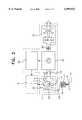
- FIG. 1is a structural diagram of the plasmotron of the cold plasma coagulator
- FIG. 2is an unit-block diagram of the cold plasma coagulator
- FIG. 3is a cross-sectional view of the resonance inductor of the cold plasma coagulator
- FIG. 4is a schematic diagram of the plasmotron case of the cold plasma coagulator
- FIG. 5is an equivalent circuit diagram to resonance characteristics of the cold plasma coagulator.
- FIGS. 6(a) to 6(d)are waveform diagrams for the power supply and resonance circuit of the cold plasma coagulator.
- FIGS. 7 and 8are structural designs of an argon free coagulator in accordance with another embodiment of the invention.
- the cold plasma coagulator of the present inventioncomprises a high frequency power supply, gas dynamic block and plasmotron.
- the power supplycomprises a rectifier, capacitor storage and voltage inverter.
- the said plasmotronis assembled in a hermetically sealed case in which a resonance inductor and dielectric tube of cylindrical cartridge are located coaxially. One end of the dielectric tube is connected to the gas dynamic block and the other end is positioned to eject plasma through an output nozzle.
- a needle corona electrodeAlong the axis of the dielectric electrode, a needle corona electrode, is located, coils of the resonance inductor consisting of low voltage and high voltage sections, the low voltage section of resonance coils is connected to an output of the voltage inverter, one pin of the high voltage section being isolated and another one connected to the needle corona electrode.
- the high voltage section of resonance inductoris provided with cylindrical multi-layer, its non-isolated pin connected to internal layer of the resonance coils and the isolated pin connected to an external layer, and the low voltage section being reeled up atop of the high voltage section in one layer.
- the plasmotron caseis constructed in a dismountable banana-shaped form, consisting of two symmetric halves. It is also preferred that the resonance inductor is wound on the fluoroplastic body whose internal and external diameters and height cover the ranges fixed by the following ratio:
- D and drepresent the external and internal diameters, respectively; and, h represents height of the fluoroplastic body.
- the cold plasma coagulator of the inventioncan generate stable flow of cold plasma even under low charge of plasma forming gas or low current of discharge, which permits decrease of the mass and dimension and efficient operation without applying active capacitor for reactive current.
- the plasmais excited by the high frequency magnetic field generated from the cavity of resonance coils and by the high frequency induction electrical field from electrode system, and this excitation process does not require additional capacitor for the conductive current.
- the cold plasma from the coagulator of the inventionis generated by unipolar induction. Therefore, the currents and potentials for the cold plasma generation obey the law of unipolar induction, and the currents recur to the power supply unit, so the consumption of energy in the plasma coagulator decreases. That is, the plasma coagulator of the invention which generates cold plasma always operates in a form of unipolar induction, so plasma energy can reach to the object through conductive medium.
- the cold plasma, generated from the plasma coagulatorcan be activated and accumulated by inductance coils during multi-dimensional parametric resonance process.
- the plasma coagulator of the inventioncomprises a high frequency power supply unit(1), gas dynamic block(2) and plasmotron(3), all of which are assembled in a cylindrical case(4) with a resonance inductor(5) and dielectric tube(6) to flow plasma forming gas(7) located coaxially.
- the power supply unitcomprises a rectifier(33), capacitor storage(34) and voltage inverter(35), for exciting the resonance coils located in the plasmotron(3) by generating a sine wave potential of 30 to 60 V, at a frequency of 50 to 150 kHz and with 50 to 100 W of power, and is constructed to allow the ejection of cold unipolar plasma(9) from output nozzle(8), which coagulates the blood bleeding from the tissue(10).
- the first end (11) of the dielectric tube(6)is connected to the gas dynamic block(2) through a plug(12) which also functions as a passage for the power supply entrance(13) to supply the resonance coil with power.
- the second end(14) of the tube(6)is hermetically connected to the cylindrical cavity(16) of plasma forming electrode(17) through a nipple(15) and under the cavity(16)the plasma forming chamber(18) is positioned.
- a needle corona electrode(19)the location of which is fixed by the aid of tubular holder(20) and flange(21).
- the tubular holder(20)is positioned at the side of radial apertures(22), through which the flow of gas arrives at the plasma forming chamber(18).
- the coils of resonance inductorinclude a low voltage section(23) and high voltage section(24), as depicted in FIG. 2, one pin(25) of the high voltage section(24) is isolated and the other (26) is connected to the needle corona electrode(19) through the tubular holder(20).
- the high voltage section(24) of resonance coilis provided with cylindrical multi-layers, whose non-isolated pin(26) is connected to the internal layer of the resonance coils and the isolated pin(25) to the external layer, respectively; and, the low voltage section(23) is wound on the high voltage section(24) in one layer of the coils.
- the resonance coilsare assembled on a dielectric fluoroplastic body(30) and isolated from each other by the aid of a thin-layer film isolator(31).
- the dielectric tube(6)is installed in the cylindrical cavity(16) of the coils.
- the power supply unit(1)comprises a low voltage block transformer-rectifier(33), capacitor storage(34) and voltage inverter(35).
- the voltage inverter(35)generates a sine wave signal of the desired resonance frequency.
- Control block(36)regulates gas pressure through the gas dynamic block(2) and controls voltage of the inverter(35) and tunes the resonance frequency of the inverter.
- the inverter(35)transforms DC voltage of 25 to 35 V into the frequency with which monovibrator can work.
- the capacity range of the plasmotron(3) of the inventionis about 50 to 100 B T , the diameter of the output nozzle(8) is less than about 1 mm, and the flow velocity of argon employed as a plasma forming gas is about 2 to 6 L/min.
- the excitation mechanism, concentration and temperature of the plasmawould be varied; however, isolation grounding by a second electrode, and conduction of current through the biological object would not be required, since the generation mechanism follows unipolar induction.
- the plasmotron caseis designed, for convenience during surgical use, as a banana-shaped form assembled from two halves(38),(39). On the narrow part(40) of the case, the dielectric plasma forming electrode(17) is connected, and at the rear side of the case, the plug(12) for conducting and supplying the gas to resonance coils located in cylindrical cavity(41) is positioned.
- the banana-shaped plasmotron case in an assembled formfacilitates convenient use of the plasma coagulator. Further, since the dielectric electrode(17) is also dismountable, the plasma nozzle with various output diameters can be employed in the plasma coagulator of the invention.
- gas dynamic block(2)Before operating the plasma coagulator, gas dynamic block(2) is connected to the plasma forming gas(helium or argon) which has fixed flow velocity level of 2 to 6 L/min, and the power supply of coagulator is switched on.
- Gas flow from the block(2)which comprises a cylinder, controller and storage unit, passes through dielectric tube(6) and intersects the central cavity(32) of resonance coils(5), where the magnetic interaction of gas flow and of high frequency magnetic field occurs. Though the ionization of the gas would not be achieved by the magnetic interaction, the gas molecules in the flowing gas are initially activated to increase the plasma generation efficiency of the coagulator.
- the gas flow in which reactive magnetic conductivity is increasedarrives at the plasma forming chamber(18) housing the dielectric electrode(17) through nipple(15) and becomes focused at the output nozzle(8) by the dielectric electrode(17) by the formation of a corona discharge on needle electrode(19), which finally results in the generation of cold plasma of about 30° C.
- plasma forming gas(7)interacts with magnetic field and further interacts with the electric field at the plasma forming chamber(18).
- FIGS. 3, 4, and 5The resonance characteristics of the coils of resonance inductor(5) are shown in FIGS. 3, 4, and 5.
- the induction excitation in the low voltage and high voltage sections(23), (24) and the gas flow in central cavity(32) and plasma forming chamber(18)are shown as an equivalent circuit in the diagram of FIG. 5.
- erepresents alternating voltage from inverter(35)
- u 1 , w 1 , and L 1represent voltage, number of turns, and inductance for the coils of low voltage section(23), respectively.
- the flow of plasma forming gasis represented as the parallel connection L n -C n : wherein, L n represents the equivalent inductance of plasma, C n represents the equivalent capacitance of the plasma and n represents the number of layers of coil.
- the mechanism of plasma generation from the coagulator of the inventionis defined by the following two emission factors: an emission of charged particles from needle electrode(19) axisymmetrically located in plasma forming chamber(18); and, an emission of the pressurized gas, such as helium or argon, in the chamber(18).
- the plasma flow(9)possesses low heat capacity due to gas excitation consisting of double stages.
- the plasma forming gas(7)is initially excited by the high frequency magnetic field in the cylindrical cavity(32) at the stage referred to as "parallel parametric resonance".
- the parallel parametric resonance of circuitis shown as an equivalent circuit diagram, including the L n -C n element.
- the gas flowis further excited by the high frequency-reactive electric field in the chamber(18), which is shown in the equivalent circuit diagram of FIG. 5 as L 2 -C 2 , being connected in series to form a serial resonant circuit.
- the high inner resistance of the parallel resonant circuitlimits the total arc current of the plasma generated from the output nozzle(8) of the plasmotron. This permits stable plasma injection, lowers the temperature of the plasma being ejected, and improves the blood coagulation efficiency of the plasma.
- the high voltage section(24)is depicted as a series resonant circuit of L 2 -C 2 (wherein, the number of turns is represented as w 2 , the current i 2 , the voltage u 2 , and the inductance L 2 , respectively).
- the potential for the isolated pin of high voltage section(24)is represented as ⁇ 1 , and the potential of the other pin ⁇ 2 .
- ⁇ 1 and ⁇ 1represent the magnetic flows of low voltage and high voltage sections, respectively, and M 12 represents the mutual inductance for said sections.
- the main feature of the coagulator under operationis shown as a parametric resonance based on the orthogonal shift of magnetic flows of ⁇ 1 and ⁇ 2 (or voltages of u 1 and u 2 of two coil sections).
- voltage u 2may be represented as the equation(1):
- the pulse voltage u 2 of resonance frequency w 0is generated from the circuit of high voltage section(24) of the inductor, and u 2 may be represented as the equation(4):
- L 20designates the average value of inductance for high voltage section(24)
- L 2 (t)may be represented as the equations(5) and (6):
- mrepresents the modulation factor of inductance L 2 .
- ⁇ 1represents the frequency of output voltage e
- C 20is the average value of capacitor for high voltage section(24) under parametric resonance state.
- ⁇ nwave resistance of the load(plasma).
- the condition of excitation for the parametric resonancemay be determined by the equation(7):
- Qis the factor of merit for the resonant circuit.
- the gas flow(7)interacts with magnetic flow ⁇ 2 through passing the dielectric tube(6) with a velocity V, and its change per time may be determined as a function of L 2 (t) as shown in FIG. 6(d), if the current i 2 consists of two counterphase harmonics:
- the high voltage section(24)functions on the active capacitor in the form of idle course (its circuit is disconnected galvanically).
- the scalar magnetic field H 0influences on the gas, as parametric induction is manifested with frequency ⁇ 0 .
- Pointing flow on the axis of the resonance coilsis defined as:
- Hrepresents the vectorial magnetic field created by low voltage section(where, the number of turns is w 1 );
- H 0represents the scalar magnetic field generated by high voltage section(where, the number of turns is w 2 ).
- E 0is the scalar electrical field generated by capacitor C 2 ;
- Eis the vectorial electrical field generated by section w 2 .
- the cold unipolar plasmais generated from the coagulator, that is, the characteristics of resonance inductance coils are changed by the scalar field E 0 and H 0 , and the bipolar electromagnetic induction is transformed into Tesla unipolar current.
- the maximum value of factor of merit for the coils under the parametric resonance statewhich is the excitation state of scalar field of E 0 and H 0 , may be achieved by constructing the structure of the fluoroplastic body as followings:
- D and drepresent external and internal diameter, respectively; and, h represents height of the fluoroplastic body.
- the excitation of plasmamay be executed without Joule heat transfer from the electrical circuit to the gas flow. Therefore, the phenomenon of cold plasma ejection can be achieved based on new mechanism of carrying the energy of scalar electrical and magnetic field in a flow of neutral gas such as helium or argon.
- the contraction and focusing of plasma flow(9)can be achieved by controlling the aperture diameter of output nozzle(8), as well as by controlling the size of chamber(18) and working pressure of the gas.
- the spontaneous polarization of section w 2transfers the characteristics of coaxial quarter wave resonator to the coil shown in FIG. 3 on scalar fields E 0 and H 0 , then considerably increases the factor of merit Q, which already does not depend on the active resistance of winding of the resonance circuit.
- the process of plasma excitationis initiated by polarized currents of section w 2 and is executed on a level of a free reactive capacitor.
- a high potentialmay be directly formed in the plasmotron by the output for the parametric resonance, and the optimum potential formed at section w 2 is 5 to 10 kV.
- the cold plasma coagulator of the present inventionsubstantially minimizes the power consumption, due to the fact that the plasma is activated by reactive currents.
- the optimum frequency for the cold plasma coagulator of the inventionis about 100 to 150 kHz, which permits the coagulator to employ the transistor inverter or amplifier with an output voltage of 30 to 60 V as the power supply unit, so that the mass and dimensional parameters of power supply unit would be considerably reduced to provide a portable plasma coagulator and that the plasma coagulator would be manufactured in an economical manner.
- the cold plasma coagulator of the present inventionhas high coagulation efficiency and can generate unipolar cold plasma to cause no electric shock and to minimize the damages of tissue during surgical operation, requiring lower energy consumption, and has simple structure to reduce the mass and dimension.
- an argon-free coagulatoris also provided, based on the cold plasma coagulator of FIGS. 1-6.
- the air adjacent to needle electrode (42)is used for plasma forming.
- the matching element (43)is preferably a high-voltage capacitor with relatively low capacitance.
- the new condition for resonance inductor (5) implementationis the following:
- Llength of wire of high voltage section (24) of resonance inductor (5).
- kinteger digit, equal or more than zero.
- ⁇wavelength, corresponding to frequency of first sequential resonance of resonance inductor (5).
- the plasma streamer (45)is formed on the edge of needle electrode (42) and forms the well visible beam with a length of about 0.5 to 2 cm (up to 1 inch) and a cross section of about 0.5 to 2 mm (up to 0.1 inch), which provides the exact targeting of plasma to treaded tissue area and sequentially reduces the risk of accidental traumatic of adjacent tissue and increases the comfort of surgeon works.
- Plasma in the airis formed due to noble gasses included in the air, such as nitrogen, argon, helium and others.
- the plasmais obtained in steady air located close to the end of the needle electrode 42, as well as air flowing through the gas channel in a dielectric electrode of the CPC.
- the air flowis optimized to form the direction of plasma beam.
- the air flow valueis close to the argon flow value as noted above with reference to FIGS. 1-6.
- the pressureis preferably about one atmosphere with the flow rate at zero.
- Air temperatureis preferably around room temperature. High humidity will result in degradation of plasma beam when air is used as a plasma forming gas.
- the capacitor 43affects the capacitance of coil 24. However, this effect is very minor due to the low value of the capacitance on capacitor 43.
- the capacitor 43is preferably a matching element, which is necessary to provide plasma forming from air only. Due to the longitudinal character of the field, which is generated by coil 24, at the end of needle electrode 42, high homogeneous high tense alternating electric field is formed. This field excites the gasses of the air and places them into a medastable state. In this state, the gas molecules are easily ionized and longitudinal electric field separates the positive and negative particles in space. As a result, the lifetime of ions and free electrons substantially extends, the temperature of plasma decreases and plasma exists in normal environmental conditions as well. Due to an alternating character of field, the effect of contraction arises and it results in forming a very thin plasma beam.
- the coil 24is configured to maximize the electric potential at the end of needle electrode 42 and becomes sufficient to excite the noble gasses to a metastable state.
- the wire, forming an inner wound,provides a quarter-wave resonator when one end of which has zero potential and the other end has high voltage potential to form the plasma.
Landscapes
- Health & Medical Sciences (AREA)
- Surgery (AREA)
- Engineering & Computer Science (AREA)
- Life Sciences & Earth Sciences (AREA)
- Biomedical Technology (AREA)
- Molecular Biology (AREA)
- Nuclear Medicine, Radiotherapy & Molecular Imaging (AREA)
- Plasma & Fusion (AREA)
- Physics & Mathematics (AREA)
- Heart & Thoracic Surgery (AREA)
- Medical Informatics (AREA)
- Otolaryngology (AREA)
- Animal Behavior & Ethology (AREA)
- General Health & Medical Sciences (AREA)
- Public Health (AREA)
- Veterinary Medicine (AREA)
- Cardiology (AREA)
- Plasma Technology (AREA)
Abstract
Description
2<h/D<3 0.3<d/D<0.5
u.sub.2 =u.sub.1 ·Ktr·n (1)
d(LI)/dt=L·dI/dt+I·dL/dt (2)
=L·I (3)
u.sub.2 =i.sub.2 ·dL/dt (4)
L.sub.2 (t)=L.sub.20 /(1-m·cos 2ω.sub.0 t) (5)
m=2/ω.sub.1 ·C.sub.20 ·ρ.sub.n (6)
ω.sub.0 =ω.sub.1 m>2Q Q=ω.sub.1 ·C.sub.20 ·ρ.sub.n (7)
ω.sub.0.sup.2 =1/L.sub.20 ·C.sub.20
Φ.sub.2 =i.sub.2 ·L.sub.2 (t) (8)
Π.sub.H =H.sub.0 ×H (9)
.h slashed..sub.E =E.sub.0 ×E (10)
2<h/D<3 0.3<d/D<0.5
L=1/4*(2k+1)λ
Claims (10)
2<h/D<3 0.3<d/D<0.5
2<h/D<3 0.3<d/D<0.5
2<h/D<3 0.3<d/D<0.5
Priority Applications (1)
| Application Number | Priority Date | Filing Date | Title |
|---|---|---|---|
| US09/159,995US6099523A (en) | 1995-06-27 | 1998-09-24 | Cold plasma coagulator |
Applications Claiming Priority (3)
| Application Number | Priority Date | Filing Date | Title |
|---|---|---|---|
| US49522895A | 1995-06-27 | 1995-06-27 | |
| US94713397A | 1997-10-08 | 1997-10-08 | |
| US09/159,995US6099523A (en) | 1995-06-27 | 1998-09-24 | Cold plasma coagulator |
Related Parent Applications (1)
| Application Number | Title | Priority Date | Filing Date |
|---|---|---|---|
| US94713397AContinuation-In-Part | 1995-06-27 | 1997-10-08 |
Publications (1)
| Publication Number | Publication Date |
|---|---|
| US6099523Atrue US6099523A (en) | 2000-08-08 |
Family
ID=27051695
Family Applications (1)
| Application Number | Title | Priority Date | Filing Date |
|---|---|---|---|
| US09/159,995Expired - LifetimeUS6099523A (en) | 1995-06-27 | 1998-09-24 | Cold plasma coagulator |
Country Status (1)
| Country | Link |
|---|---|
| US (1) | US6099523A (en) |
Cited By (108)
| Publication number | Priority date | Publication date | Assignee | Title |
|---|---|---|---|---|
| US20030071223A1 (en)* | 2001-06-25 | 2003-04-17 | Hartley Frank T. | Field ionizing elements and applications thereof |
| US6565558B1 (en)* | 1998-09-01 | 2003-05-20 | Heinz Lindenmeier | High-frequency device for generating a plasma arc for the treatment of biological tissue |
| US6723091B2 (en)* | 2000-02-22 | 2004-04-20 | Gyrus Medical Limited | Tissue resurfacing |
| US20040110297A1 (en)* | 2001-02-09 | 2004-06-10 | Sousuke Miyoshi | Method of transffering selected molecules |
| US20040186470A1 (en)* | 2000-02-22 | 2004-09-23 | Gyrus Medical Limited | Tissue resurfacing |
| US20050149012A1 (en)* | 2000-02-22 | 2005-07-07 | Gyrus Medical Limited | Tissue resurfacing |
| US20060009763A1 (en)* | 2000-02-22 | 2006-01-12 | Rhytech Limited | Tissue treatment system |
| WO2006048650A1 (en)* | 2004-11-05 | 2006-05-11 | Dow Corning Ireland Limited | Plasma system |
| US20060116674A1 (en)* | 2000-02-22 | 2006-06-01 | Rhytec Limited | Method of regenerating the recticular architecture of the dermis |
| US20060189976A1 (en)* | 2005-01-18 | 2006-08-24 | Alma Lasers International | System and method for treating biological tissue with a plasma gas discharge |
| US20070027446A1 (en)* | 2000-02-22 | 2007-02-01 | Rhytec Limited | Method of removing a tattoo |
| US20070106349A1 (en)* | 2005-01-18 | 2007-05-10 | Ziv Karni | System and method for heating biological tissue via rf energy |
| US20090054896A1 (en)* | 2005-04-25 | 2009-02-26 | Gregory Fridman | Control of mucus membrane bleeding with cold plasma |
| US20100125267A1 (en)* | 2008-11-14 | 2010-05-20 | Psm Inc. | Plasma Gun for Bio/Medical Treatment |
| EP2189125A1 (en)* | 2008-11-25 | 2010-05-26 | Postech Academy-Industry Foundation | Coagulation apparatus |
| US20100145253A1 (en)* | 2005-04-25 | 2010-06-10 | Drexel University | Methods for non-thermal application of gas plasma to living tissue |
| US20100162893A1 (en)* | 2008-12-31 | 2010-07-01 | Gary Gerard Gogolin | Reflux Trap Device |
| US7785322B2 (en) | 2000-02-22 | 2010-08-31 | Plasmogen Inc. | Tissue treatment system |
| US20100305565A1 (en)* | 2000-08-01 | 2010-12-02 | Arqos Surgical, Inc. | Voltage threshold ablation apparatus |
| US7862564B2 (en) | 2000-02-22 | 2011-01-04 | Plasmogen Inc. | Method of remodelling stretch marks |
| RU2409398C1 (en)* | 2009-06-22 | 2011-01-20 | Общество с ограниченной ответственностью Инновационно-производственная компания "ПЛАЗМЕННОЕ ОБОРУДОВАНИЕ" | Arrangement for preventive and therapeutic radiation |
| US7928338B2 (en) | 2007-02-02 | 2011-04-19 | Plasma Surgical Investments Ltd. | Plasma spraying device and method |
| WO2011055368A3 (en)* | 2009-11-09 | 2011-07-14 | Ionmed Ltd | Plasma head for tissue welding |
| US8030849B2 (en) | 2007-08-06 | 2011-10-04 | Plasma Surgical Investments Limited | Pulsed plasma device and method for generating pulsed plasma |
| RU2434656C1 (en)* | 2010-08-04 | 2011-11-27 | Георгий Цыренович Дамбаев | Method of stopping intra-operation haemorrhage |
| US20120015322A1 (en)* | 2008-12-23 | 2012-01-19 | Geoffrey Morgan Lloyd | Tooth whitening ii |
| US8105325B2 (en) | 2005-07-08 | 2012-01-31 | Plasma Surgical Investments Limited | Plasma-generating device, plasma surgical device, use of a plasma-generating device and method of generating a plasma |
| US8109928B2 (en)* | 2005-07-08 | 2012-02-07 | Plasma Surgical Investments Limited | Plasma-generating device, plasma surgical device and use of plasma surgical device |
| US8222822B2 (en) | 2009-10-27 | 2012-07-17 | Tyco Healthcare Group Lp | Inductively-coupled plasma device |
| US20120245580A1 (en)* | 2011-03-21 | 2012-09-27 | Arqos Surgical, Inc. | Medical ablation system and method of use |
| EP2299922A4 (en)* | 2008-05-30 | 2012-10-03 | Univ Colorado State Res Found | SYSTEM, METHOD AND DEVICE FOR PRODUCING PLASMA |
| US20120253265A1 (en)* | 2009-03-16 | 2012-10-04 | Drexel University | Methods and devices for the treatment and prevention of malignancy in enteric diseases using non-thermal plasma |
| WO2012153332A2 (en) | 2011-05-09 | 2012-11-15 | Ionmed Ltd | Tissue welding using plasma |
| WO2013040469A1 (en)* | 2011-09-15 | 2013-03-21 | Cold Plasma Medical Technologies, Inc. | Harmonic cold plasma devices and associated methods |
| US8460283B1 (en)* | 2009-04-03 | 2013-06-11 | Old Dominion University | Low temperature plasma generator |
| US8613742B2 (en) | 2010-01-29 | 2013-12-24 | Plasma Surgical Investments Limited | Methods of sealing vessels using plasma |
| US8668687B2 (en) | 2010-07-29 | 2014-03-11 | Covidien Lp | System and method for removing medical implants |
| US8735766B2 (en) | 2007-08-06 | 2014-05-27 | Plasma Surgical Investments Limited | Cathode assembly and method for pulsed plasma generation |
| US8834462B2 (en) | 2010-06-01 | 2014-09-16 | Covidien Lp | System and method for sensing tissue characteristics |
| US8896211B2 (en)* | 2013-01-16 | 2014-11-25 | Orteron (T.O) Ltd | Physical means and methods for inducing regenerative effects on living tissues and fluids |
| US20140378892A1 (en)* | 2011-06-01 | 2014-12-25 | Michael Keidar | System And Method For Cold Plasma Therapy |
| US8994270B2 (en) | 2008-05-30 | 2015-03-31 | Colorado State University Research Foundation | System and methods for plasma application |
| US9028656B2 (en) | 2008-05-30 | 2015-05-12 | Colorado State University Research Foundation | Liquid-gas interface plasma device |
| US9089319B2 (en) | 2010-07-22 | 2015-07-28 | Plasma Surgical Investments Limited | Volumetrically oscillating plasma flows |
| US9204918B2 (en) | 2011-09-28 | 2015-12-08 | RELIGN Corporation | Medical ablation system and method of use |
| US20160023183A1 (en)* | 2013-01-16 | 2016-01-28 | Orteron (T.O) Ltd. | Method for controlling biological processes in microorganisms |
| US9247983B2 (en) | 2011-11-14 | 2016-02-02 | Arqos Surgical, Inc. | Medical instrument and method of use |
| US9272359B2 (en) | 2008-05-30 | 2016-03-01 | Colorado State University Research Foundation | Liquid-gas interface plasma device |
| US9288886B2 (en) | 2008-05-30 | 2016-03-15 | Colorado State University Research Foundation | Plasma-based chemical source device and method of use thereof |
| US9295280B2 (en) | 2012-12-11 | 2016-03-29 | Plasmology4, Inc. | Method and apparatus for cold plasma food contact surface sanitation |
| WO2016079742A1 (en) | 2014-11-19 | 2016-05-26 | Technion Research & Development Foundation Limited | Cold plasma generating system |
| US9387269B2 (en) | 2011-01-28 | 2016-07-12 | Bovie Medical Corporation | Cold plasma jet hand sanitizer |
| US9437401B2 (en) | 2013-12-20 | 2016-09-06 | Plasmology4, Inc. | System and method for plasma treatment using directional dielectric barrier discharge energy system |
| US9472382B2 (en) | 2007-04-23 | 2016-10-18 | Plasmology4, Inc. | Cold plasma annular array methods and apparatus |
| US9521736B2 (en) | 2007-04-23 | 2016-12-13 | Plasmology4, Inc. | Cold plasma electroporation of medication and associated methods |
| US20160361558A1 (en)* | 2015-06-10 | 2016-12-15 | Plasmology4, Inc. | Internal cold plasma system |
| US9532826B2 (en) | 2013-03-06 | 2017-01-03 | Covidien Lp | System and method for sinus surgery |
| WO2017005830A1 (en)* | 2015-07-07 | 2017-01-12 | Olympus Winter & Ibe Gmbh | Electrosurgical instrument for argon-plasma coagulation, and a method for operating same |
| US9555145B2 (en) | 2013-03-13 | 2017-01-31 | Covidien Lp | System and method for biofilm remediation |
| WO2017034863A1 (en)* | 2015-08-24 | 2017-03-02 | Smith & Nephew, Inc. | Electrosurgical wand with a spacer and with an active electrode, an associated system and an ablation method including generating a plasma |
| US9585675B1 (en) | 2015-10-23 | 2017-03-07 | RELIGN Corporation | Arthroscopic devices and methods |
| US9603656B1 (en) | 2015-10-23 | 2017-03-28 | RELIGN Corporation | Arthroscopic devices and methods |
| CN106667572A (en)* | 2017-01-04 | 2017-05-17 | 电子科技大学 | Plasma beam diameter adjustable plasma gas scalpel |
| US9656095B2 (en) | 2007-04-23 | 2017-05-23 | Plasmology4, Inc. | Harmonic cold plasma devices and associated methods |
| US9681907B2 (en) | 2010-01-28 | 2017-06-20 | Bovie Medical Corporation | Electrosurgical apparatus to generate a dual plasma stream and method thereof |
| US9681913B2 (en) | 2015-04-21 | 2017-06-20 | RELIGN Corporation | Arthroscopic devices and methods |
| US20170183632A1 (en)* | 2015-11-05 | 2017-06-29 | U.S. Patent Innovations, LLC | System and Method for Cold Atmospheric Plasma Treatment on Cancer Stem Cells |
| US20170303381A1 (en)* | 2015-01-12 | 2017-10-19 | Applied Plasma, LLC | Plasma device with a replaceable (plug-in) discharge tube |
| US9913358B2 (en) | 2005-07-08 | 2018-03-06 | Plasma Surgical Investments Limited | Plasma-generating device, plasma surgical device and use of a plasma surgical device |
| US20180103991A1 (en)* | 2016-10-18 | 2018-04-19 | Btl Holdings Limited | Device and method for tissue treatment by combination of energy and plasma |
| JP2018511445A (en)* | 2015-04-15 | 2018-04-26 | コンメッド コーポレイション | Argon beam coagulation surgical device |
| US10004556B2 (en) | 2013-05-10 | 2018-06-26 | Corinth MedTech, Inc. | Tissue resecting devices and methods |
| US10022140B2 (en) | 2016-02-04 | 2018-07-17 | RELIGN Corporation | Arthroscopic devices and methods |
| US10399723B2 (en) | 2015-03-11 | 2019-09-03 | Plasmology4, Inc. | Container treatment system |
| IT201800007505A1 (en)* | 2018-07-25 | 2020-01-25 | Universita' Degli Studi Magna Graecia Di Catanzaro- Dipartimento Di Scienze Mediche E Chirurgiche | Biomedical plasma device for blood coagulation |
| US10595889B2 (en) | 2016-04-11 | 2020-03-24 | RELIGN Corporation | Arthroscopic devices and methods |
| US10881444B2 (en) | 2010-11-08 | 2021-01-05 | Apyx Medical Corporation | Electrosurgical apparatus with retractable blade |
| US10912598B2 (en)* | 2017-08-04 | 2021-02-09 | Us Patent Innovations, Llc | Diffusive applicator for cold atmospheric plasma system |
| US11006995B2 (en)* | 2009-08-25 | 2021-05-18 | Leibniz-Institut Fuer Plasmaforschung Und Technologie E.V. | Device for the planar treatment of areas of human or animal skin or mucous membrane surfaces by means of a cold atmospheric pressure plasma |
| US11065023B2 (en) | 2017-03-17 | 2021-07-20 | RELIGN Corporation | Arthroscopic devices and methods |
| US11172953B2 (en) | 2016-04-11 | 2021-11-16 | RELIGN Corporation | Arthroscopic devices and methods |
| US11185690B2 (en) | 2016-05-23 | 2021-11-30 | BTL Healthcare Technologies, a.s. | Systems and methods for tissue treatment |
| US11207119B2 (en) | 2016-03-11 | 2021-12-28 | RELIGN Corporation | Arthroscopic devices and methods |
| US11247039B2 (en) | 2016-05-03 | 2022-02-15 | Btl Healthcare Technologies A.S. | Device including RF source of energy and vacuum system |
| US11247063B2 (en) | 2019-04-11 | 2022-02-15 | Btl Healthcare Technologies A.S. | Methods and devices for aesthetic treatment of biological structures by radiofrequency and magnetic energy |
| US11253717B2 (en) | 2015-10-29 | 2022-02-22 | Btl Healthcare Technologies A.S. | Aesthetic method of biological structure treatment by magnetic field |
| US11253718B2 (en) | 2015-07-01 | 2022-02-22 | Btl Healthcare Technologies A.S. | High power time varying magnetic field therapy |
| US11266852B2 (en) | 2016-07-01 | 2022-03-08 | Btl Healthcare Technologies A.S. | Aesthetic method of biological structure treatment by magnetic field |
| US11272973B2 (en) | 2015-01-28 | 2022-03-15 | Apyx Medical Corporation | Cold plasma electrosurgical apparatus with bent tip applicator |
| US11426231B2 (en) | 2017-01-11 | 2022-08-30 | RELIGN Corporation | Arthroscopic devices and methods |
| US20220304738A1 (en)* | 2021-03-25 | 2022-09-29 | Aesthetics Biomedical, Inc. | Plasma fractionation device for skin rejuvenation |
| US11464993B2 (en) | 2016-05-03 | 2022-10-11 | Btl Healthcare Technologies A.S. | Device including RF source of energy and vacuum system |
| US11464994B2 (en) | 2016-05-10 | 2022-10-11 | Btl Medical Solutions A.S. | Aesthetic method of biological structure treatment by magnetic field |
| US11484727B2 (en) | 2016-07-01 | 2022-11-01 | Btl Medical Solutions A.S. | Aesthetic method of biological structure treatment by magnetic field |
| US11491342B2 (en) | 2015-07-01 | 2022-11-08 | Btl Medical Solutions A.S. | Magnetic stimulation methods and devices for therapeutic treatments |
| US11491329B2 (en) | 2020-05-04 | 2022-11-08 | Btl Healthcare Technologies A.S. | Device and method for unattended treatment of a patient |
| US11534619B2 (en) | 2016-05-10 | 2022-12-27 | Btl Medical Solutions A.S. | Aesthetic method of biological structure treatment by magnetic field |
| US11602390B2 (en) | 2017-01-30 | 2023-03-14 | Apyx Medical Corporation | Electrosurgical apparatus with flexible shaft |
| US11612758B2 (en) | 2012-07-05 | 2023-03-28 | Btl Medical Solutions A.S. | Device for repetitive nerve stimulation in order to break down fat tissue means of inductive magnetic fields |
| US11633596B2 (en) | 2020-05-04 | 2023-04-25 | Btl Healthcare Technologies A.S. | Device and method for unattended treatment of a patient |
| EP2670331B1 (en)* | 2011-02-04 | 2023-10-04 | Arqos Surgical, Inc. | Medical ablation system |
| US11877788B2 (en) | 2017-05-30 | 2024-01-23 | Apyx Medical Corporation | Electrosurgical apparatus with robotic tip |
| US11882643B2 (en) | 2020-08-28 | 2024-01-23 | Plasma Surgical, Inc. | Systems, methods, and devices for generating predominantly radially expanded plasma flow |
| US11896816B2 (en) | 2021-11-03 | 2024-02-13 | Btl Healthcare Technologies A.S. | Device and method for unattended treatment of a patient |
| US12064163B2 (en) | 2021-10-13 | 2024-08-20 | Btl Medical Solutions A.S. | Methods and devices for aesthetic treatment of biological structures by radiofrequency and magnetic energy |
| US12156689B2 (en) | 2019-04-11 | 2024-12-03 | Btl Medical Solutions A.S. | Methods and devices for aesthetic treatment of biological structures by radiofrequency and magnetic energy |
| US12167888B2 (en) | 2016-03-10 | 2024-12-17 | RELIGN Corporation | Arthroscopic devices and methods |
| US12274494B2 (en) | 2016-08-16 | 2025-04-15 | Btl Healthcare Technologies A.S. | Treatment device |
Citations (12)
| Publication number | Priority date | Publication date | Assignee | Title |
|---|---|---|---|---|
| US3434476A (en)* | 1966-04-07 | 1969-03-25 | Robert F Shaw | Plasma arc scalpel |
| US3903891A (en)* | 1968-01-12 | 1975-09-09 | Hogle Kearns Int | Method and apparatus for generating plasma |
| US3938525A (en)* | 1972-05-15 | 1976-02-17 | Hogle-Kearns International | Plasma surgery |
| US3991764A (en)* | 1973-11-28 | 1976-11-16 | Purdue Research Foundation | Plasma arc scalpel |
| US4040426A (en)* | 1976-01-16 | 1977-08-09 | Valleylab, Inc. | Electrosurgical method and apparatus for initiating an electrical discharge in an inert gas flow |
| US4429694A (en)* | 1981-07-06 | 1984-02-07 | C. R. Bard, Inc. | Electrosurgical generator |
| US4562838A (en)* | 1981-01-23 | 1986-01-07 | Walker William S | Electrosurgery instrument |
| US4589411A (en)* | 1985-02-08 | 1986-05-20 | Aaron Friedman | Electrosurgical spark-gap cutting blade |
| US4781175A (en)* | 1986-04-08 | 1988-11-01 | C. R. Bard, Inc. | Electrosurgical conductive gas stream technique of achieving improved eschar for coagulation |
| US4943290A (en)* | 1987-06-23 | 1990-07-24 | Concept Inc. | Electrolyte purging electrode tip |
| US5041110A (en)* | 1989-07-10 | 1991-08-20 | Beacon Laboratories, Inc. | Cart for mobilizing and interfacing use of an electrosurgical generator and inert gas supply |
| US5207675A (en)* | 1991-07-15 | 1993-05-04 | Jerome Canady | Surgical coagulation device |
- 1998
- 1998-09-24USUS09/159,995patent/US6099523A/ennot_activeExpired - Lifetime
Patent Citations (12)
| Publication number | Priority date | Publication date | Assignee | Title |
|---|---|---|---|---|
| US3434476A (en)* | 1966-04-07 | 1969-03-25 | Robert F Shaw | Plasma arc scalpel |
| US3903891A (en)* | 1968-01-12 | 1975-09-09 | Hogle Kearns Int | Method and apparatus for generating plasma |
| US3938525A (en)* | 1972-05-15 | 1976-02-17 | Hogle-Kearns International | Plasma surgery |
| US3991764A (en)* | 1973-11-28 | 1976-11-16 | Purdue Research Foundation | Plasma arc scalpel |
| US4040426A (en)* | 1976-01-16 | 1977-08-09 | Valleylab, Inc. | Electrosurgical method and apparatus for initiating an electrical discharge in an inert gas flow |
| US4562838A (en)* | 1981-01-23 | 1986-01-07 | Walker William S | Electrosurgery instrument |
| US4429694A (en)* | 1981-07-06 | 1984-02-07 | C. R. Bard, Inc. | Electrosurgical generator |
| US4589411A (en)* | 1985-02-08 | 1986-05-20 | Aaron Friedman | Electrosurgical spark-gap cutting blade |
| US4781175A (en)* | 1986-04-08 | 1988-11-01 | C. R. Bard, Inc. | Electrosurgical conductive gas stream technique of achieving improved eschar for coagulation |
| US4943290A (en)* | 1987-06-23 | 1990-07-24 | Concept Inc. | Electrolyte purging electrode tip |
| US5041110A (en)* | 1989-07-10 | 1991-08-20 | Beacon Laboratories, Inc. | Cart for mobilizing and interfacing use of an electrosurgical generator and inert gas supply |
| US5207675A (en)* | 1991-07-15 | 1993-05-04 | Jerome Canady | Surgical coagulation device |
Cited By (223)
| Publication number | Priority date | Publication date | Assignee | Title |
|---|---|---|---|---|
| US6565558B1 (en)* | 1998-09-01 | 2003-05-20 | Heinz Lindenmeier | High-frequency device for generating a plasma arc for the treatment of biological tissue |
| US20070027446A1 (en)* | 2000-02-22 | 2007-02-01 | Rhytec Limited | Method of removing a tattoo |
| US6723091B2 (en)* | 2000-02-22 | 2004-04-20 | Gyrus Medical Limited | Tissue resurfacing |
| US7862564B2 (en) | 2000-02-22 | 2011-01-04 | Plasmogen Inc. | Method of remodelling stretch marks |
| US20040186470A1 (en)* | 2000-02-22 | 2004-09-23 | Gyrus Medical Limited | Tissue resurfacing |
| US20050149012A1 (en)* | 2000-02-22 | 2005-07-07 | Gyrus Medical Limited | Tissue resurfacing |
| US20050256519A1 (en)* | 2000-02-22 | 2005-11-17 | Rhytec Limited | Tissue resurfacing |
| US20060009763A1 (en)* | 2000-02-22 | 2006-01-12 | Rhytech Limited | Tissue treatment system |
| US7785322B2 (en) | 2000-02-22 | 2010-08-31 | Plasmogen Inc. | Tissue treatment system |
| US7335199B2 (en) | 2000-02-22 | 2008-02-26 | Rhytec Limited | Tissue resurfacing |
| US20060116674A1 (en)* | 2000-02-22 | 2006-06-01 | Rhytec Limited | Method of regenerating the recticular architecture of the dermis |
| US7300436B2 (en) | 2000-02-22 | 2007-11-27 | Rhytec Limited | Tissue resurfacing |
| US8333763B2 (en) | 2000-08-01 | 2012-12-18 | Arqos Surgical, Inc. | Voltage threshold ablation apparatus |
| US20100305565A1 (en)* | 2000-08-01 | 2010-12-02 | Arqos Surgical, Inc. | Voltage threshold ablation apparatus |
| US7402435B2 (en)* | 2001-02-09 | 2008-07-22 | Bbk Bio Corporation | Method of transferring a selected molecule into a cell |
| US20040110297A1 (en)* | 2001-02-09 | 2004-06-10 | Sousuke Miyoshi | Method of transffering selected molecules |
| US20030071223A1 (en)* | 2001-06-25 | 2003-04-17 | Hartley Frank T. | Field ionizing elements and applications thereof |
| WO2006048650A1 (en)* | 2004-11-05 | 2006-05-11 | Dow Corning Ireland Limited | Plasma system |
| WO2006048649A1 (en)* | 2004-11-05 | 2006-05-11 | Dow Corning Ireland Limited | Plasma system |
| EA010367B1 (en)* | 2004-11-05 | 2008-08-29 | Дау Корнинг Айэлэнд Лимитед | Plasma system |
| EA010940B1 (en)* | 2004-11-05 | 2008-12-30 | Дау Корнинг Айэлэнд Лимитед | Plasma system |
| US20090065485A1 (en)* | 2004-11-05 | 2009-03-12 | Dow Corning Ireland Ltd. | Plasma System |
| US20090142514A1 (en)* | 2004-11-05 | 2009-06-04 | Dow Corning Ireland Ltd. | Plasma System |
| US20070106349A1 (en)* | 2005-01-18 | 2007-05-10 | Ziv Karni | System and method for heating biological tissue via rf energy |
| US7630774B2 (en) | 2005-01-18 | 2009-12-08 | Alma Lasers Ltd. | System and method for heating biological tissue via RF energy |
| US20090326528A1 (en)* | 2005-01-18 | 2009-12-31 | Alma Lasers Ltd. | System and method for heating biological tissue via rf energy |
| US8150532B2 (en) | 2005-01-18 | 2012-04-03 | Alma Lasers Ltd. | System and method for heating biological tissue via RF energy |
| US20060189976A1 (en)* | 2005-01-18 | 2006-08-24 | Alma Lasers International | System and method for treating biological tissue with a plasma gas discharge |
| US9215788B2 (en) | 2005-01-18 | 2015-12-15 | Alma Lasers Ltd. | System and method for treating biological tissue with a plasma gas discharge |
| US20130310731A1 (en)* | 2005-04-25 | 2013-11-21 | Drexel University | Methods for non-thermal applications of gas plasma to living tissue |
| US20090054896A1 (en)* | 2005-04-25 | 2009-02-26 | Gregory Fridman | Control of mucus membrane bleeding with cold plasma |
| US8725248B2 (en)* | 2005-04-25 | 2014-05-13 | Drexel University | Methods for non-thermal applications of gas plasma to living tissue |
| US8521274B2 (en) | 2005-04-25 | 2013-08-27 | Drexel University | Methods for non-thermal application of gas plasma to living tissue |
| US8388618B2 (en)* | 2005-04-25 | 2013-03-05 | Drexel University | Control of mucus membrane bleeding with cold plasma |
| US20100145253A1 (en)* | 2005-04-25 | 2010-06-10 | Drexel University | Methods for non-thermal application of gas plasma to living tissue |
| US8337494B2 (en)* | 2005-07-08 | 2012-12-25 | Plasma Surgical Investments Limited | Plasma-generating device having a plasma chamber |
| US20120143184A1 (en)* | 2005-07-08 | 2012-06-07 | Nikolay Suslov | Plasma-generating device having a plasma chamber |
| US9913358B2 (en) | 2005-07-08 | 2018-03-06 | Plasma Surgical Investments Limited | Plasma-generating device, plasma surgical device and use of a plasma surgical device |
| US12075552B2 (en) | 2005-07-08 | 2024-08-27 | Plasma Surgical, Inc. | Plasma-generating device, plasma surgical device and use of a plasma surgical device |
| US8105325B2 (en) | 2005-07-08 | 2012-01-31 | Plasma Surgical Investments Limited | Plasma-generating device, plasma surgical device, use of a plasma-generating device and method of generating a plasma |
| US8109928B2 (en)* | 2005-07-08 | 2012-02-07 | Plasma Surgical Investments Limited | Plasma-generating device, plasma surgical device and use of plasma surgical device |
| US10201067B2 (en) | 2005-07-08 | 2019-02-05 | Plasma Surgical Investments Limited | Plasma-generating device, plasma surgical device and use of a plasma surgical device |
| US8465487B2 (en) | 2005-07-08 | 2013-06-18 | Plasma Surgical Investments Limited | Plasma-generating device having a throttling portion |
| EP1810626A3 (en)* | 2006-01-18 | 2007-09-12 | Alma Lasers Ltd | System for treating biological tissue with a plasma gas discharge |
| EP1810626A2 (en) | 2006-01-18 | 2007-07-25 | Alma Lasers Ltd | System for treating biological tissue with a plasma gas discharge |
| US7928338B2 (en) | 2007-02-02 | 2011-04-19 | Plasma Surgical Investments Ltd. | Plasma spraying device and method |
| US9472382B2 (en) | 2007-04-23 | 2016-10-18 | Plasmology4, Inc. | Cold plasma annular array methods and apparatus |
| US10064263B2 (en) | 2007-04-23 | 2018-08-28 | Plasmology4, Inc. | Cold plasma treatment devices and associated methods |
| US9521736B2 (en) | 2007-04-23 | 2016-12-13 | Plasmology4, Inc. | Cold plasma electroporation of medication and associated methods |
| US9192776B2 (en) | 2007-04-23 | 2015-11-24 | Plasmology4, Inc. | Harmonic cold plasma devices and associated methods |
| US9558918B2 (en)* | 2007-04-23 | 2017-01-31 | Plasmology4, Inc. | Cold plasma treatment devices and associated methods |
| US20150127079A1 (en)* | 2007-04-23 | 2015-05-07 | Cold Plasma Medical Technologies, Inc. | Cold Plasma Treatment Devices and Associated Methods |
| US9006976B2 (en) | 2007-04-23 | 2015-04-14 | Plasmology4, Inc. | Cold plasma treatment devices and associated methods |
| US9861829B2 (en) | 2007-04-23 | 2018-01-09 | Plasmology4, Inc. | Cold plasma electroporation of medication and associated methods |
| US9570273B2 (en) | 2007-04-23 | 2017-02-14 | Plasmology4, Inc. | Cold plasma treatment devices and associated methods |
| US9646808B2 (en) | 2007-04-23 | 2017-05-09 | Plasmology4, Inc. | Cold plasma annular array methods and apparatus |
| US9656095B2 (en) | 2007-04-23 | 2017-05-23 | Plasmology4, Inc. | Harmonic cold plasma devices and associated methods |
| US8735766B2 (en) | 2007-08-06 | 2014-05-27 | Plasma Surgical Investments Limited | Cathode assembly and method for pulsed plasma generation |
| US8030849B2 (en) | 2007-08-06 | 2011-10-04 | Plasma Surgical Investments Limited | Pulsed plasma device and method for generating pulsed plasma |
| US20170136253A1 (en)* | 2008-02-27 | 2017-05-18 | Plasmology4, Inc. | Cold Plasma Treatment Devices and Associated Methods |
| US9288886B2 (en) | 2008-05-30 | 2016-03-15 | Colorado State University Research Foundation | Plasma-based chemical source device and method of use thereof |
| US9272359B2 (en) | 2008-05-30 | 2016-03-01 | Colorado State University Research Foundation | Liquid-gas interface plasma device |
| US9287091B2 (en) | 2008-05-30 | 2016-03-15 | Colorado State University Research Foundation | System and methods for plasma application |
| US8994270B2 (en) | 2008-05-30 | 2015-03-31 | Colorado State University Research Foundation | System and methods for plasma application |
| EP2299922A4 (en)* | 2008-05-30 | 2012-10-03 | Univ Colorado State Res Found | SYSTEM, METHOD AND DEVICE FOR PRODUCING PLASMA |
| US9028656B2 (en) | 2008-05-30 | 2015-05-12 | Colorado State University Research Foundation | Liquid-gas interface plasma device |
| US8575843B2 (en) | 2008-05-30 | 2013-11-05 | Colorado State University Research Foundation | System, method and apparatus for generating plasma |
| WO2010009103A3 (en)* | 2008-07-18 | 2010-04-15 | Drexel University | Control of mucus membrane bleeding with cold plasma |
| US20100125267A1 (en)* | 2008-11-14 | 2010-05-20 | Psm Inc. | Plasma Gun for Bio/Medical Treatment |
| US20100130973A1 (en)* | 2008-11-25 | 2010-05-27 | Postech Academy Industry Foundation | Coagulation apparatus using cold plasma |
| EP2189125A1 (en)* | 2008-11-25 | 2010-05-26 | Postech Academy-Industry Foundation | Coagulation apparatus |
| JP2010125320A (en)* | 2008-11-25 | 2010-06-10 | Pohang Univ Of Science & Technology Academy-Industry Cooperation | Hemostasis device using low temperature plasma |
| US8187265B2 (en) | 2008-11-25 | 2012-05-29 | Postech Academy Industry Foundation | Coagulation apparatus using cold plasma |
| US20120015322A1 (en)* | 2008-12-23 | 2012-01-19 | Geoffrey Morgan Lloyd | Tooth whitening ii |
| US8114181B2 (en)* | 2008-12-31 | 2012-02-14 | Bovie Medical Corporation | Reflux trap device |
| US20100162893A1 (en)* | 2008-12-31 | 2010-07-01 | Gary Gerard Gogolin | Reflux Trap Device |
| US8992518B2 (en)* | 2009-03-16 | 2015-03-31 | Drexel University | Methods and devices for the treatment and prevention of malignancy in enteric diseases using non-thermal plasma |
| US20120253265A1 (en)* | 2009-03-16 | 2012-10-04 | Drexel University | Methods and devices for the treatment and prevention of malignancy in enteric diseases using non-thermal plasma |
| US8460283B1 (en)* | 2009-04-03 | 2013-06-11 | Old Dominion University | Low temperature plasma generator |
| RU2409398C1 (en)* | 2009-06-22 | 2011-01-20 | Общество с ограниченной ответственностью Инновационно-производственная компания "ПЛАЗМЕННОЕ ОБОРУДОВАНИЕ" | Arrangement for preventive and therapeutic radiation |
| US11006995B2 (en)* | 2009-08-25 | 2021-05-18 | Leibniz-Institut Fuer Plasmaforschung Und Technologie E.V. | Device for the planar treatment of areas of human or animal skin or mucous membrane surfaces by means of a cold atmospheric pressure plasma |
| US8222822B2 (en) | 2009-10-27 | 2012-07-17 | Tyco Healthcare Group Lp | Inductively-coupled plasma device |
| US8878434B2 (en) | 2009-10-27 | 2014-11-04 | Covidien Lp | Inductively-coupled plasma device |
| US9060750B2 (en) | 2009-11-09 | 2015-06-23 | Ionmed Ltd. | Plasma head for tissue welding |
| WO2011055368A3 (en)* | 2009-11-09 | 2011-07-14 | Ionmed Ltd | Plasma head for tissue welding |
| US9681907B2 (en) | 2010-01-28 | 2017-06-20 | Bovie Medical Corporation | Electrosurgical apparatus to generate a dual plasma stream and method thereof |
| US8613742B2 (en) | 2010-01-29 | 2013-12-24 | Plasma Surgical Investments Limited | Methods of sealing vessels using plasma |
| US8834462B2 (en) | 2010-06-01 | 2014-09-16 | Covidien Lp | System and method for sensing tissue characteristics |
| US9974594B2 (en) | 2010-06-01 | 2018-05-22 | Covidien Lp | System and method for sensing tissue characteristics |
| US10966775B2 (en) | 2010-06-01 | 2021-04-06 | Covidien Lp | System and method for sensing tissue characteristics |
| US10492845B2 (en) | 2010-07-22 | 2019-12-03 | Plasma Surgical Investments Limited | Volumetrically oscillating plasma flows |
| US10631911B2 (en) | 2010-07-22 | 2020-04-28 | Plasma Surgical Investments Limited | Volumetrically oscillating plasma flows |
| US12023081B2 (en) | 2010-07-22 | 2024-07-02 | Plasma Surgical, Inc. | Volumetrically oscillating plasma flows |
| US9089319B2 (en) | 2010-07-22 | 2015-07-28 | Plasma Surgical Investments Limited | Volumetrically oscillating plasma flows |
| US10463418B2 (en) | 2010-07-22 | 2019-11-05 | Plasma Surgical Investments Limited | Volumetrically oscillating plasma flows |
| US8668687B2 (en) | 2010-07-29 | 2014-03-11 | Covidien Lp | System and method for removing medical implants |
| RU2434656C1 (en)* | 2010-08-04 | 2011-11-27 | Георгий Цыренович Дамбаев | Method of stopping intra-operation haemorrhage |
| US10881444B2 (en) | 2010-11-08 | 2021-01-05 | Apyx Medical Corporation | Electrosurgical apparatus with retractable blade |
| US11903630B2 (en) | 2010-11-08 | 2024-02-20 | Apyx Medical Corporation | Electrosurgical apparatus with retractable blade |
| US9387269B2 (en) | 2011-01-28 | 2016-07-12 | Bovie Medical Corporation | Cold plasma jet hand sanitizer |
| US9601317B2 (en) | 2011-01-28 | 2017-03-21 | Bovie Medical Corporation | Cold plasma sanitizing device |
| EP2670331B1 (en)* | 2011-02-04 | 2023-10-04 | Arqos Surgical, Inc. | Medical ablation system |
| US9277954B2 (en)* | 2011-03-21 | 2016-03-08 | Arqos Surgical, Inc. | Medical ablation system and method of use |
| US10292751B2 (en)* | 2011-03-21 | 2019-05-21 | RELIGN Corporation | Medical ablation system and method of use |
| US20130296849A1 (en)* | 2011-03-21 | 2013-11-07 | Arqos Surgical, Inc. | Medical ablation system and method of use |
| US20160157916A1 (en)* | 2011-03-21 | 2016-06-09 | RELIGN Corporation | Medical ablation system and method of use |
| US20120245580A1 (en)* | 2011-03-21 | 2012-09-27 | Arqos Surgical, Inc. | Medical ablation system and method of use |
| US20210145502A1 (en)* | 2011-03-21 | 2021-05-20 | RELIGN Corporation | Medical ablation system and method of use |
| US8323280B2 (en)* | 2011-03-21 | 2012-12-04 | Arqos Surgical, Inc. | Medical ablation system and method of use |
| US11712282B2 (en)* | 2011-03-21 | 2023-08-01 | RELIGN Corporation | Medical ablation system and method of use |
| WO2012153332A2 (en) | 2011-05-09 | 2012-11-15 | Ionmed Ltd | Tissue welding using plasma |
| US20140378892A1 (en)* | 2011-06-01 | 2014-12-25 | Michael Keidar | System And Method For Cold Plasma Therapy |
| US10213614B2 (en)* | 2011-06-01 | 2019-02-26 | U.S. Patent Innovations, LLC | System and method for cold plasma therapy |
| WO2013040469A1 (en)* | 2011-09-15 | 2013-03-21 | Cold Plasma Medical Technologies, Inc. | Harmonic cold plasma devices and associated methods |
| US9592085B2 (en) | 2011-09-28 | 2017-03-14 | RELIGN Corporation | Medical ablation system and method of use |
| US9795434B2 (en) | 2011-09-28 | 2017-10-24 | RELIGN Corporation | Medical ablation system and method of use |
| US11229477B2 (en) | 2011-09-28 | 2022-01-25 | RELIGN Corporation | Medical ablation system and method of use |
| US11672586B2 (en) | 2011-09-28 | 2023-06-13 | RELIGN Corporation | Medical ablation system and method of use |
| US9204918B2 (en) | 2011-09-28 | 2015-12-08 | RELIGN Corporation | Medical ablation system and method of use |
| US9247983B2 (en) | 2011-11-14 | 2016-02-02 | Arqos Surgical, Inc. | Medical instrument and method of use |
| US10342603B2 (en) | 2011-11-14 | 2019-07-09 | RELIGN Corporation | Medical instrument and method of use |
| US11612758B2 (en) | 2012-07-05 | 2023-03-28 | Btl Medical Solutions A.S. | Device for repetitive nerve stimulation in order to break down fat tissue means of inductive magnetic fields |
| US9295280B2 (en) | 2012-12-11 | 2016-03-29 | Plasmology4, Inc. | Method and apparatus for cold plasma food contact surface sanitation |
| US10266802B2 (en)* | 2013-01-16 | 2019-04-23 | Orteron (T.O) Ltd. | Method for controlling biological processes in microorganisms |
| US8896211B2 (en)* | 2013-01-16 | 2014-11-25 | Orteron (T.O) Ltd | Physical means and methods for inducing regenerative effects on living tissues and fluids |
| US20160023183A1 (en)* | 2013-01-16 | 2016-01-28 | Orteron (T.O) Ltd. | Method for controlling biological processes in microorganisms |
| US10524848B2 (en) | 2013-03-06 | 2020-01-07 | Covidien Lp | System and method for sinus surgery |
| US9532826B2 (en) | 2013-03-06 | 2017-01-03 | Covidien Lp | System and method for sinus surgery |
| US9555145B2 (en) | 2013-03-13 | 2017-01-31 | Covidien Lp | System and method for biofilm remediation |
| US10004556B2 (en) | 2013-05-10 | 2018-06-26 | Corinth MedTech, Inc. | Tissue resecting devices and methods |
| US10170281B2 (en) | 2013-12-20 | 2019-01-01 | Plasmology4, Inc. | System and method for plasma treatment using directional dielectric barrier discharge energy system |
| US9437401B2 (en) | 2013-12-20 | 2016-09-06 | Plasmology4, Inc. | System and method for plasma treatment using directional dielectric barrier discharge energy system |
| WO2016079742A1 (en) | 2014-11-19 | 2016-05-26 | Technion Research & Development Foundation Limited | Cold plasma generating system |
| US11006994B2 (en) | 2014-11-19 | 2021-05-18 | Technion Research & Development Foundation Limited | Cold plasma generating system |
| US12059190B2 (en) | 2014-11-19 | 2024-08-13 | Technion Research & Development Foundation Limited | Cold plasma generating system |
| US20170303381A1 (en)* | 2015-01-12 | 2017-10-19 | Applied Plasma, LLC | Plasma device with a replaceable (plug-in) discharge tube |
| US11272973B2 (en) | 2015-01-28 | 2022-03-15 | Apyx Medical Corporation | Cold plasma electrosurgical apparatus with bent tip applicator |
| US10399723B2 (en) | 2015-03-11 | 2019-09-03 | Plasmology4, Inc. | Container treatment system |
| JP2018511445A (en)* | 2015-04-15 | 2018-04-26 | コンメッド コーポレイション | Argon beam coagulation surgical device |
| JP2019217293A (en)* | 2015-04-15 | 2019-12-26 | コンメッド コーポレイション | Surgical apparatus for argon beam coagulation |
| JP7171524B2 (en) | 2015-04-15 | 2022-11-15 | コンメッド コーポレイション | Argon beam coagulation surgical unit |
| US10582966B2 (en) | 2015-04-21 | 2020-03-10 | RELIGN Corporation | Arthroscopic devices and methods |
| US9681913B2 (en) | 2015-04-21 | 2017-06-20 | RELIGN Corporation | Arthroscopic devices and methods |
| US20160361558A1 (en)* | 2015-06-10 | 2016-12-15 | Plasmology4, Inc. | Internal cold plasma system |
| US11253718B2 (en) | 2015-07-01 | 2022-02-22 | Btl Healthcare Technologies A.S. | High power time varying magnetic field therapy |
| US11491342B2 (en) | 2015-07-01 | 2022-11-08 | Btl Medical Solutions A.S. | Magnetic stimulation methods and devices for therapeutic treatments |
| US11266850B2 (en) | 2015-07-01 | 2022-03-08 | Btl Healthcare Technologies A.S. | High power time varying magnetic field therapy |
| WO2017005830A1 (en)* | 2015-07-07 | 2017-01-12 | Olympus Winter & Ibe Gmbh | Electrosurgical instrument for argon-plasma coagulation, and a method for operating same |
| WO2017034863A1 (en)* | 2015-08-24 | 2017-03-02 | Smith & Nephew, Inc. | Electrosurgical wand with a spacer and with an active electrode, an associated system and an ablation method including generating a plasma |
| US11234759B2 (en) | 2015-10-23 | 2022-02-01 | RELIGN Corporation | Arthroscopic devices and methods |
| US9585675B1 (en) | 2015-10-23 | 2017-03-07 | RELIGN Corporation | Arthroscopic devices and methods |
| US10568685B2 (en) | 2015-10-23 | 2020-02-25 | RELIGN Corporation | Arthroscopic devices and methods |
| US10327842B2 (en) | 2015-10-23 | 2019-06-25 | RELIGN Corporation | Arthroscopic devices and methods |
| US11419670B2 (en) | 2015-10-23 | 2022-08-23 | RELIGN Corporation | Arthroscopic devices and methods |
| US12023090B2 (en) | 2015-10-23 | 2024-07-02 | RELIGN Corporation | Arthroscopic devices and methods |
| US9603656B1 (en) | 2015-10-23 | 2017-03-28 | RELIGN Corporation | Arthroscopic devices and methods |
| US11253717B2 (en) | 2015-10-29 | 2022-02-22 | Btl Healthcare Technologies A.S. | Aesthetic method of biological structure treatment by magnetic field |
| US20170183632A1 (en)* | 2015-11-05 | 2017-06-29 | U.S. Patent Innovations, LLC | System and Method for Cold Atmospheric Plasma Treatment on Cancer Stem Cells |
| US10329535B2 (en)* | 2015-11-05 | 2019-06-25 | Us Patent Innovations, Llc | System and method for cold atmospheric plasma treatment on cancer stem cells |
| US11771456B2 (en) | 2016-02-04 | 2023-10-03 | RELIGN Corporation | Arthroscopic devices and methods |
| US10022140B2 (en) | 2016-02-04 | 2018-07-17 | RELIGN Corporation | Arthroscopic devices and methods |
| US12167888B2 (en) | 2016-03-10 | 2024-12-17 | RELIGN Corporation | Arthroscopic devices and methods |
| US11207119B2 (en) | 2016-03-11 | 2021-12-28 | RELIGN Corporation | Arthroscopic devices and methods |
| US12096969B2 (en) | 2016-03-11 | 2024-09-24 | RELIGN Corporation | Arthroscopic devices and methods |
| US12042167B2 (en) | 2016-04-11 | 2024-07-23 | RELIGN Corporation | Arthroscopic devices and methods |
| US11622784B2 (en) | 2016-04-11 | 2023-04-11 | RELIGN Corporation | Arthroscopic devices and methods |
| US10595889B2 (en) | 2016-04-11 | 2020-03-24 | RELIGN Corporation | Arthroscopic devices and methods |
| US11172953B2 (en) | 2016-04-11 | 2021-11-16 | RELIGN Corporation | Arthroscopic devices and methods |
| US11464993B2 (en) | 2016-05-03 | 2022-10-11 | Btl Healthcare Technologies A.S. | Device including RF source of energy and vacuum system |
| US11883643B2 (en) | 2016-05-03 | 2024-01-30 | Btl Healthcare Technologies A.S. | Systems and methods for treatment of a patient including RF and electrical energy |
| US11247039B2 (en) | 2016-05-03 | 2022-02-15 | Btl Healthcare Technologies A.S. | Device including RF source of energy and vacuum system |
| US11602629B2 (en) | 2016-05-03 | 2023-03-14 | Btl Healthcare Technologies A.S. | Systems and methods for treatment of a patient including rf and electrical energy |
| US12109426B2 (en) | 2016-05-10 | 2024-10-08 | Btl Medical Solutions A.S. | Aesthetic method of biological structure treatment by magnetic field |
| US11534619B2 (en) | 2016-05-10 | 2022-12-27 | Btl Medical Solutions A.S. | Aesthetic method of biological structure treatment by magnetic field |
| US11590356B2 (en) | 2016-05-10 | 2023-02-28 | Btl Medical Solutions A.S. | Aesthetic method of biological structure treatment by magnetic field |
| US11464994B2 (en) | 2016-05-10 | 2022-10-11 | Btl Medical Solutions A.S. | Aesthetic method of biological structure treatment by magnetic field |
| US12151120B2 (en) | 2016-05-10 | 2024-11-26 | Btl Medical Solutions A.S. | Aesthetic method of biological structure treatment by magnetic field |
| US11691024B2 (en) | 2016-05-10 | 2023-07-04 | Btl Medical Solutions A.S. | Aesthetic method of biological structure treatment by magnetic field |
| US11458307B2 (en) | 2016-05-23 | 2022-10-04 | Btl Healthcare Technologies A.S. | Systems and methods for tissue treatment |
| US11896821B2 (en) | 2016-05-23 | 2024-02-13 | Btl Healthcare Technologies A.S. | Systems and methods for tissue treatment |
| US11878162B2 (en) | 2016-05-23 | 2024-01-23 | Btl Healthcare Technologies A.S. | Systems and methods for tissue treatment |
| US11185690B2 (en) | 2016-05-23 | 2021-11-30 | BTL Healthcare Technologies, a.s. | Systems and methods for tissue treatment |
| US11623083B2 (en) | 2016-05-23 | 2023-04-11 | Btl Healthcare Technologies A.S. | Systems and methods for tissue treatment |
| US11794029B2 (en) | 2016-07-01 | 2023-10-24 | Btl Medical Solutions A.S. | Aesthetic method of biological structure treatment by magnetic field |
| US11607556B2 (en) | 2016-07-01 | 2023-03-21 | Btl Medical Solutions A.S. | Aesthetic method of biological structure treatment by magnetic field |
| US11524171B2 (en) | 2016-07-01 | 2022-12-13 | Btl Medical Solutions A.S. | Aesthetic method of biological structure treatment by magnetic field |
| US11679270B2 (en) | 2016-07-01 | 2023-06-20 | Btl Medical Solutions A.S. | Aesthetic method of biological structure treatment by magnetic field |
| US11628308B2 (en) | 2016-07-01 | 2023-04-18 | Btl Medical Solutions A.S. | Aesthetic method of biological structure treatment by magnetic field |
| US11497925B2 (en) | 2016-07-01 | 2022-11-15 | Btl Medical Solutions A.S. | Aesthetic method of biological structure treatment by magnetic field |
| US11484727B2 (en) | 2016-07-01 | 2022-11-01 | Btl Medical Solutions A.S. | Aesthetic method of biological structure treatment by magnetic field |
| US12109427B2 (en) | 2016-07-01 | 2024-10-08 | Btl Medical Solutions A.S. | Aesthetic method of biological structure treatment by magnetic field |
| US11266852B2 (en) | 2016-07-01 | 2022-03-08 | Btl Healthcare Technologies A.S. | Aesthetic method of biological structure treatment by magnetic field |
| US12274494B2 (en) | 2016-08-16 | 2025-04-15 | Btl Healthcare Technologies A.S. | Treatment device |
| US20180103991A1 (en)* | 2016-10-18 | 2018-04-19 | Btl Holdings Limited | Device and method for tissue treatment by combination of energy and plasma |
| CN106667572B (en)* | 2017-01-04 | 2019-06-21 | 电子科技大学 | A plasma gas scalpel with adjustable plasma beam diameter |
| CN106667572A (en)* | 2017-01-04 | 2017-05-17 | 电子科技大学 | Plasma beam diameter adjustable plasma gas scalpel |
| US11426231B2 (en) | 2017-01-11 | 2022-08-30 | RELIGN Corporation | Arthroscopic devices and methods |
| US11602390B2 (en) | 2017-01-30 | 2023-03-14 | Apyx Medical Corporation | Electrosurgical apparatus with flexible shaft |
| US12004765B2 (en) | 2017-03-17 | 2024-06-11 | RELIGN Corporation | Arthroscopic devices and methods |
| US11065023B2 (en) | 2017-03-17 | 2021-07-20 | RELIGN Corporation | Arthroscopic devices and methods |
| US11877788B2 (en) | 2017-05-30 | 2024-01-23 | Apyx Medical Corporation | Electrosurgical apparatus with robotic tip |
| US10912598B2 (en)* | 2017-08-04 | 2021-02-09 | Us Patent Innovations, Llc | Diffusive applicator for cold atmospheric plasma system |
| IT201800007505A1 (en)* | 2018-07-25 | 2020-01-25 | Universita' Degli Studi Magna Graecia Di Catanzaro- Dipartimento Di Scienze Mediche E Chirurgiche | Biomedical plasma device for blood coagulation |
| US11484725B2 (en) | 2019-04-11 | 2022-11-01 | Btl Medical Solutions A.S. | Methods and devices for aesthetic treatment of biological structures by radiofrequency and magnetic energy |
| US11247063B2 (en) | 2019-04-11 | 2022-02-15 | Btl Healthcare Technologies A.S. | Methods and devices for aesthetic treatment of biological structures by radiofrequency and magnetic energy |
| US12156689B2 (en) | 2019-04-11 | 2024-12-03 | Btl Medical Solutions A.S. | Methods and devices for aesthetic treatment of biological structures by radiofrequency and magnetic energy |
| US12076576B2 (en) | 2019-04-11 | 2024-09-03 | Btl Medical Solutions A.S. | Methods and devices for aesthetic treatment of biological structures by radiofrequency and magnetic energy |
| US11826565B2 (en) | 2020-05-04 | 2023-11-28 | Btl Healthcare Technologies A.S. | Device and method for unattended treatment of a patient |
| US11806528B2 (en) | 2020-05-04 | 2023-11-07 | Btl Healthcare Technologies A.S. | Device and method for unattended treatment of a patient |
| US12427307B2 (en) | 2020-05-04 | 2025-09-30 | Btl Healthcare Technologies A.S. | Device and method for unattended treatment of a patient |
| US12311170B2 (en) | 2020-05-04 | 2025-05-27 | Btl Healthcare Technologies A.S. | Device and method for unattended treatment of a patient |
| US11878167B2 (en) | 2020-05-04 | 2024-01-23 | Btl Healthcare Technologies A.S. | Device and method for unattended treatment of a patient |
| US12029905B2 (en) | 2020-05-04 | 2024-07-09 | Btl Healthcare Technologies A.S. | Device and method for unattended treatment of a patient |
| US11633596B2 (en) | 2020-05-04 | 2023-04-25 | Btl Healthcare Technologies A.S. | Device and method for unattended treatment of a patient |
| US11679255B2 (en) | 2020-05-04 | 2023-06-20 | Btl Healthcare Technologies A.S. | Device and method for unattended treatment of a patient |
| US11813451B2 (en) | 2020-05-04 | 2023-11-14 | Btl Healthcare Technologies A.S. | Device and method for unattended treatment of a patient |
| US11491329B2 (en) | 2020-05-04 | 2022-11-08 | Btl Healthcare Technologies A.S. | Device and method for unattended treatment of a patient |
| US12058801B2 (en) | 2020-08-28 | 2024-08-06 | Plasma Surgical, Inc. | Systems, methods, and devices for generating predominantly radially expanded plasma flow |
| US11882643B2 (en) | 2020-08-28 | 2024-01-23 | Plasma Surgical, Inc. | Systems, methods, and devices for generating predominantly radially expanded plasma flow |
| US20220304738A1 (en)* | 2021-03-25 | 2022-09-29 | Aesthetics Biomedical, Inc. | Plasma fractionation device for skin rejuvenation |
| US12064163B2 (en) | 2021-10-13 | 2024-08-20 | Btl Medical Solutions A.S. | Methods and devices for aesthetic treatment of biological structures by radiofrequency and magnetic energy |
| US12115365B2 (en) | 2021-11-03 | 2024-10-15 | Btl Healthcare Technologies A.S. | Device and method for unattended treatment of a patient |
| US11896816B2 (en) | 2021-11-03 | 2024-02-13 | Btl Healthcare Technologies A.S. | Device and method for unattended treatment of a patient |
Similar Documents
| Publication | Publication Date | Title |
|---|---|---|
| US6099523A (en) | Cold plasma coagulator | |
| EP0787465B1 (en) | Cold plasma coagulator | |
| US5414324A (en) | One atmosphere, uniform glow discharge plasma | |
| US5300860A (en) | Capacitively coupled RF fluorescent lamp with RF magnetic enhancement | |
| EP1034747A1 (en) | Electrosurgery system and instrument | |
| US11791133B2 (en) | Plasma generating apparatus and method for operating same | |
| US20240276628A1 (en) | System and method for plasma generation of nitric acid | |
| US4253047A (en) | Starting electrodes for solenoidal electric field discharge lamps | |
| KR20230006780A (en) | Plasma reforming apparatus for a target gas under atmospheric pressure | |
| US20020039546A1 (en) | Ozone generator | |
| US20090011940A1 (en) | System and method for using a vacuum core high temperature superconducting resonator | |
| KR102486653B1 (en) | Atmospheric Pressure Plasma Generation Apparatus | |
| KR20240150405A (en) | The Plasma Generation Apparatus And The Operational Method Of The Same | |
| KR0138190B1 (en) | Cold plasma coagulator | |
| JP3808511B2 (en) | Pulse gas laser generator | |
| RU2191113C1 (en) | Apparatus for treating materials by means of high-frequency electric discharge | |
| JP2707357B2 (en) | Gas laser device | |
| JPH06310781A (en) | Solid-state laser device | |
| KR102479772B1 (en) | Atmospheric Pressure Plasma Generation Apparatus | |
| US4912738A (en) | Magnetically energized pulser | |
| JP2757226B2 (en) | Gas laser device | |
| RU2002116218A (en) | RADIATION SOURCE BASED ON PLASMA FOCUS WITH AN IMPROVED PULSE POWER SYSTEM | |
| JP2836509B2 (en) | Magnetron drive power supply and plasma generator having the same | |
| KR800001141B1 (en) | Electrodeless discharge lamp | |
| CN119676925A (en) | A radio frequency plasma generator based on transformer coupling |
Legal Events
| Date | Code | Title | Description |
|---|---|---|---|
| AS | Assignment | Owner name:JUMP TECHNOLOGIES LIMITED, HONG KONG Free format text:ASSIGNMENT OF ASSIGNORS INTEREST;ASSIGNORS:KIM, SOO-IN;LISIN, VLADIMIR NIKOLAEVICH;GERMEN, BEKKER;AND OTHERS;REEL/FRAME:009601/0524 Effective date:19981106 | |
| STCF | Information on status: patent grant | Free format text:PATENTED CASE | |
| REMI | Maintenance fee reminder mailed | ||
| REIN | Reinstatement after maintenance fee payment confirmed | ||
| FP | Lapsed due to failure to pay maintenance fee | Effective date:20040808 | |
| FEPP | Fee payment procedure | Free format text:PETITION RELATED TO MAINTENANCE FEES FILED (ORIGINAL EVENT CODE: PMFP); ENTITY STATUS OF PATENT OWNER: SMALL ENTITY | |
| FEPP | Fee payment procedure | Free format text:PETITION RELATED TO MAINTENANCE FEES GRANTED (ORIGINAL EVENT CODE: PMFG); ENTITY STATUS OF PATENT OWNER: SMALL ENTITY | |
| FPAY | Fee payment | Year of fee payment:4 | |
| SULP | Surcharge for late payment | ||
| PRDP | Patent reinstated due to the acceptance of a late maintenance fee | Effective date:20051104 | |
| AS | Assignment | Owner name:UNIPOLAR PLASMA TECHNOLOGIES, LLC, FLORIDA Free format text:ASSIGNMENT OF ASSIGNORS INTEREST;ASSIGNOR:JUMP TECHNOLOGIES LIMITED;REEL/FRAME:017230/0551 Effective date:20051125 | |
| FPAY | Fee payment | Year of fee payment:8 | |
| AS | Assignment | Owner name:BOVIE MEDICAL CORPORATION, FLORIDA Free format text:ASSIGNMENT OF ASSIGNORS INTEREST;ASSIGNOR:UNIPOLAR PLASMA TECHNOLOGIES, LLC;REEL/FRAME:025398/0584 Effective date:20101122 | |
| FEPP | Fee payment procedure | Free format text:PAYOR NUMBER ASSIGNED (ORIGINAL EVENT CODE: ASPN); ENTITY STATUS OF PATENT OWNER: SMALL ENTITY | |
| FPAY | Fee payment | Year of fee payment:12 | |
| AS | Assignment | Owner name:MIDCAP FUNDING IV TRUST, MARYLAND Free format text:SECURITY INTEREST;ASSIGNOR:APYX MEDICAL CORPORATION;REEL/FRAME:062913/0001 Effective date:20230217 | |
| AS | Assignment | Owner name:APYX MEDICAL CORPORATION, FLORIDA Free format text:RELEASE BY SECURED PARTY;ASSIGNOR:MIDCAP FUNDING IV TRUST;REEL/FRAME:065612/0105 Effective date:20231108 |