US6099493A - Continuous autotransfusion filtration system - Google Patents
Continuous autotransfusion filtration systemDownload PDFInfo
- Publication number
- US6099493A US6099493AUS08/851,976US85197697AUS6099493AUS 6099493 AUS6099493 AUS 6099493AUS 85197697 AUS85197697 AUS 85197697AUS 6099493 AUS6099493 AUS 6099493A
- Authority
- US
- United States
- Prior art keywords
- blood
- filter
- collection chamber
- outlet
- patient
- Prior art date
- Legal status (The legal status is an assumption and is not a legal conclusion. Google has not performed a legal analysis and makes no representation as to the accuracy of the status listed.)
- Expired - Lifetime
Links
- 238000001914filtrationMethods0.000titleclaimsabstractdescription35
- 239000012530fluidSubstances0.000claimsabstractdescription40
- 238000004891communicationMethods0.000claimsabstractdescription14
- 210000001124body fluidAnatomy0.000claimsdescription12
- 239000010839body fluidSubstances0.000claimsdescription12
- 210000004369bloodAnatomy0.000abstractdescription78
- 239000008280bloodSubstances0.000abstractdescription78
- 208000007536ThrombosisDiseases0.000abstractdescription16
- 238000010992refluxMethods0.000abstractdescription12
- 230000000750progressive effectEffects0.000abstractdescription4
- 238000007789sealingMethods0.000abstractdescription3
- XLYOFNOQVPJJNP-UHFFFAOYSA-NwaterSubstancesOXLYOFNOQVPJJNP-UHFFFAOYSA-N0.000description26
- 238000001802infusionMethods0.000description17
- 210000003281pleural cavityAnatomy0.000description14
- 230000009471actionEffects0.000description10
- 239000007789gasSubstances0.000description10
- 239000000356contaminantSubstances0.000description7
- 239000007788liquidSubstances0.000description6
- 210000004072lungAnatomy0.000description5
- 238000000034methodMethods0.000description5
- 210000000038chestAnatomy0.000description4
- 229920000728polyesterPolymers0.000description4
- 230000008569processEffects0.000description4
- 208000015181infectious diseaseDiseases0.000description3
- 238000005192partitionMethods0.000description3
- 239000011148porous materialSubstances0.000description3
- 210000000988bone and boneAnatomy0.000description2
- 238000013461designMethods0.000description2
- 239000004744fabricSubstances0.000description2
- 238000011010flushing procedureMethods0.000description2
- 238000012546transferMethods0.000description2
- 206010067484Adverse reactionDiseases0.000description1
- 208000035473Communicable diseaseDiseases0.000description1
- 206010011224CoughDiseases0.000description1
- 206010014561EmphysemaDiseases0.000description1
- 102000009123FibrinHuman genes0.000description1
- 108010073385FibrinProteins0.000description1
- BWGVNKXGVNDBDI-UHFFFAOYSA-NFibrin monomerChemical compoundCNC(=O)CNC(=O)CNBWGVNKXGVNDBDI-UHFFFAOYSA-N0.000description1
- 102000008946FibrinogenHuman genes0.000description1
- 108010049003FibrinogenProteins0.000description1
- 230000006838adverse reactionEffects0.000description1
- 230000005540biological transmissionEffects0.000description1
- 230000005587bubblingEffects0.000description1
- 230000007812deficiencyEffects0.000description1
- 238000011161developmentMethods0.000description1
- 238000010586diagramMethods0.000description1
- 201000010099diseaseDiseases0.000description1
- 208000037265diseases, disorders, signs and symptomsDiseases0.000description1
- 235000012489doughnutsNutrition0.000description1
- 230000009977dual effectEffects0.000description1
- 210000003743erythrocyteAnatomy0.000description1
- 229950003499fibrinDrugs0.000description1
- 229940012952fibrinogenDrugs0.000description1
- 229920002457flexible plasticPolymers0.000description1
- 239000012634fragmentSubstances0.000description1
- 230000008570general processEffects0.000description1
- 208000014674injuryDiseases0.000description1
- 238000004519manufacturing processMethods0.000description1
- 239000000463materialSubstances0.000description1
- 239000012528membraneSubstances0.000description1
- 239000002245particleSubstances0.000description1
- 230000037361pathwayEffects0.000description1
- 210000002381plasmaAnatomy0.000description1
- 229920002635polyurethanePolymers0.000description1
- 239000004814polyurethaneSubstances0.000description1
- 230000001681protective effectEffects0.000description1
- 238000005086pumpingMethods0.000description1
- 230000001105regulatory effectEffects0.000description1
- 238000009877renderingMethods0.000description1
- 230000000241respiratory effectEffects0.000description1
- 230000004202respiratory functionEffects0.000description1
- 230000029058respiratory gaseous exchangeEffects0.000description1
- 238000001356surgical procedureMethods0.000description1
- 210000000115thoracic cavityAnatomy0.000description1
- 210000001519tissueAnatomy0.000description1
- 230000008733traumaEffects0.000description1
- 230000000007visual effectEffects0.000description1
Images


Classifications
- A—HUMAN NECESSITIES
- A61—MEDICAL OR VETERINARY SCIENCE; HYGIENE
- A61M—DEVICES FOR INTRODUCING MEDIA INTO, OR ONTO, THE BODY; DEVICES FOR TRANSDUCING BODY MEDIA OR FOR TAKING MEDIA FROM THE BODY; DEVICES FOR PRODUCING OR ENDING SLEEP OR STUPOR
- A61M1/00—Suction or pumping devices for medical purposes; Devices for carrying-off, for treatment of, or for carrying-over, body-liquids; Drainage systems
- A61M1/60—Containers for suction drainage, adapted to be used with an external suction source
- A61M1/61—Two- or three-bottle systems for underwater drainage, e.g. for chest cavity drainage
- A—HUMAN NECESSITIES
- A61—MEDICAL OR VETERINARY SCIENCE; HYGIENE
- A61M—DEVICES FOR INTRODUCING MEDIA INTO, OR ONTO, THE BODY; DEVICES FOR TRANSDUCING BODY MEDIA OR FOR TAKING MEDIA FROM THE BODY; DEVICES FOR PRODUCING OR ENDING SLEEP OR STUPOR
- A61M1/00—Suction or pumping devices for medical purposes; Devices for carrying-off, for treatment of, or for carrying-over, body-liquids; Drainage systems
- A61M1/60—Containers for suction drainage, adapted to be used with an external suction source
- A61M1/63—Containers for suction drainage, adapted to be used with an external suction source with means for emptying the suction container, e.g. by interrupting suction
- A61M1/631—Emptying the suction container without interrupting suction
- A—HUMAN NECESSITIES
- A61—MEDICAL OR VETERINARY SCIENCE; HYGIENE
- A61M—DEVICES FOR INTRODUCING MEDIA INTO, OR ONTO, THE BODY; DEVICES FOR TRANSDUCING BODY MEDIA OR FOR TAKING MEDIA FROM THE BODY; DEVICES FOR PRODUCING OR ENDING SLEEP OR STUPOR
- A61M1/00—Suction or pumping devices for medical purposes; Devices for carrying-off, for treatment of, or for carrying-over, body-liquids; Drainage systems
- A61M1/36—Other treatment of blood in a by-pass of the natural circulatory system, e.g. temperature adaptation, irradiation ; Extra-corporeal blood circuits
- A61M1/3621—Extra-corporeal blood circuits
- A61M1/3627—Degassing devices; Buffer reservoirs; Drip chambers; Blood filters
- A—HUMAN NECESSITIES
- A61—MEDICAL OR VETERINARY SCIENCE; HYGIENE
- A61M—DEVICES FOR INTRODUCING MEDIA INTO, OR ONTO, THE BODY; DEVICES FOR TRANSDUCING BODY MEDIA OR FOR TAKING MEDIA FROM THE BODY; DEVICES FOR PRODUCING OR ENDING SLEEP OR STUPOR
- A61M2205/00—General characteristics of the apparatus
- A61M2205/75—General characteristics of the apparatus with filters
- A61M2205/7545—General characteristics of the apparatus with filters for solid matter, e.g. microaggregates
- A—HUMAN NECESSITIES
- A61—MEDICAL OR VETERINARY SCIENCE; HYGIENE
- A61M—DEVICES FOR INTRODUCING MEDIA INTO, OR ONTO, THE BODY; DEVICES FOR TRANSDUCING BODY MEDIA OR FOR TAKING MEDIA FROM THE BODY; DEVICES FOR PRODUCING OR ENDING SLEEP OR STUPOR
- A61M2205/00—General characteristics of the apparatus
- A61M2205/75—General characteristics of the apparatus with filters
- A61M2205/7554—General characteristics of the apparatus with filters with means for unclogging or regenerating filters
Definitions
- the present inventionrelates to a system for draining shed blood from the body cavity of a patient and reinfusing clean, filtered blood back to the patient, and more specifically to a chest drainage unit (CDU) that includes a progressive filtration system for filtering out blood clots and other contaminants at both the inlet and outlet ports inside the CDU's collection chamber. More particularly, this invention relates to a high flow, micron filter assembly that refilters blood that collects at the bottom portion of the collection chamber prior to reinfusion to the patient with the assembly further including a drop tube that permits the refiltered blood to exit at an outlet port located at the top portion of the CDU.
- CDUchest drainage unit
- a CDUis an apparatus for suctioning gases and liquids from the pleural cavity of patients.
- the pleural cavitylies within the rib cage above the diaphragm and is surrounded by the pleural membrane.
- the pleural cavitycontains both lungs, which in their normal expanded state fill the pleural cavity.
- Several conditions and diseasessuch as interventional surgery, trauma, emphysema and various infections can cause a build up of liquid and gases around the lungs in the intrapleural space. When this happens, it causes the lungs to collapse to a volume much less than that of the pleural cavity, thereby severely impairing breathing functions of the patient.
- the lungscan be re-expanded to their normal state to fill the pleural cavity by draining the liquid and gases from the intrapleural space using a CDU.
- CDUsare also used during autotransfusion for recovering autologous blood from the patient's pleural and mediastinal cavities and transfusing that blood back into the patient.
- Autotransfusionoffers significant advantages over normal transfusion procedures which use homologous blood from other humans.
- Autologous bloodreduces the risk of adverse reactions and transmission of infectious disease while supplying a readily available and safe source of compatible blood to the patient.
- CDUsare being designed to both evacuate fluids from the intrapleural space and autotransfuse shed autologous blood back into the patient.
- U.S. Pat. No. 4,114,416 to Karwoski et al.illustrates the prior art development of autotransfusion CDUs.
- the deviceincludes a collection chamber for the collection of fluid from the pleural cavity, a water seal chamber for preventing passage of gas from the atmosphere into the patient's pleural and mediastinal cavities, and a manometer chamber for regulating the degree of vacuum in the system.
- An inlet port of the collection chamberis connected to the patient's pleural cavity via a thoracotomy tube that deposits shed blood and gases into the collection chamber.
- a large area gross filtersuch as a fabric or an open-pore sponge filter, is used to remove blood clots and gross particles from incoming fluids.
- the bloodcollects at the bottom portion of the collection chamber until reinfusion is effected and the blood is drained through an outlet port located at the bottom portion of the collection chamber.
- the Karwoski et al. deviceis also placed in fluid flow communication with a blood compatible pump set through tubing that connects the pump to the outlet port and permits the collected blood to drain therethrough for reinfusion to the patient.
- a microaggregate filterthat is normally interposed between the outlet of the collection chamber and the patient can also become clogged if clots are not refiltered prior to exiting the collection chamber.
- a practitionermust take the time to replace the entire blood infusion set which exposes the patient to undesirable risks, such as infection, caused by the time delay in clearing or replacing the fluid pathway between the CDU and the patient and reestablishing the autotransfusion process.
- interruption of the autotransfusion processmight require the practitioner to substitute homologous blood that could be contaminated or incompatible with the patient's own blood.
- the present inventionovercomes and substantially alleviates the deficiencies in the prior art by providing a progressive filtration system that removes unwanted contaminants from collected blood prior to reinfusion to the patient.
- the filtration system of the present inventioncomprises a gross filter for filtering incoming blood at the inlet portion of the collection chamber and a fine filter assembly located at the bottom portion of the collection chamber that refilters collected blood prior to reinfusion of that blood back to the patient.
- the filter assemblyincludes a valve cap at the top portion of the assembly that functions as a one way valve that permits reflux of later developing blood clots that might clog the tubing once the blood has already passed through the assembly.
- valve capis adapted for sealing engagement with a drop tube that places the filter assembly in fluid flow communication with the outlet of the collection chamber located at the top portion of the chamber.
- the egress of blood from the top portion of the collection chamberpermits for easier handling and set up by the practitioner when establishing the autotransfusion system.
- Another object of the present inventionis to provide an apparatus having inlet and outlet ports with a progressive filtration system that includes a gross filter for initially filtering out contaminants at the inlet port and a fine filter for refiltering later developing contaminants at the outlet port.
- a further object of the present inventionis to provide a fine filter assembly that includes a conduit means that permits refiltered blood to exit at an outlet port located at the top portion of the apparatus.
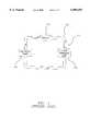
- FIG. 1is a simplified block diagram showing the basic operation of a prior art autotransfusion system
- FIG. 2is a partial cross section showing an exploded view of an autotransfusion chest drainage unit according to the present invention
- FIG. 3is a perspective view of the micron filter according to the present invention.
- FIG. 4is a cross section view of the filter body and valve cap according to the present invention.
- FIG. 5is a perspective view of the valve cap according to the present invention.
- FIG. 6is a section pictorial of FIG. 5 according to the present invention.
- FIG. 7is a perspective view of the filter assembly with a partial rendering of the polyester screen for illustrating the orientation of the drop tube within the assembly;
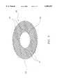
- FIG. 8is a perspective view of the filter disc according to the present invention.
- an embodiment of the continuous autotransfusion filtration systemmade in accordance with the principles of the present invention, referred to generally by reference 10, is provided for the refiltering of collected blood deposited at the bottom portion of chest drainage unit's collection chamber prior to reinfusion of that blood back to the patient.
- FIG. 1A prior art continuous autotransfusion system is shown in FIG. 1.
- the basic configuration of an autotransfusion system 11comprises a CDU 12 for sterile collection and if desired, transfer of shed fluids from a patient 13, a blood compatible infusion pump 14 placed in fluid flow communication with CDU 12 for reinfusing shed blood back to patient 13, and infusion tubing 15 for use as a conduit to transfer the blood between autotransfusion system 11 and patient 13.
- Liquid flow Adenotes the direction of the fluid flow within system 11.
- autotransfusion system 11operates by using CDU 12 for the sterile collection of blood and fluids drawn from patient 13, and simultaneous reinfusion of those fluids back to the circulatory system of patient 13.
- the general process of autotransfusing a patient's bloodbegins by drawing fluids from the patient's pleural and mediastinal cavities using a suction source (not shown) located at CDU 12 to create a positive liquid flow A through the autotransfusion system 11.
- the suction sourceforces shed body fluids from patient 13 through infusion tubing 15 and into the collection chamber (not shown) of CDU 12.
- FIG. 2as fluid enters collection chamber 16 at inlet port 19, it is run through a gross filter 20 which traps macroscopic debris such as blood clots, bone fragments and the like that become entrained in blood or other body fluids.
- Infusion tubing 15may be made of any suitable flexible plastic material, for example polyurethane or PVC, for use in transmitting fluids and gas throughout system 11.
- An autotransfusion CDU 12consists of a standard three chamber unit found in the prior art comprising a collection chamber 16, a water seal chamber 17 and suction control chamber 18.
- Collection chamber 16is designed to receive fluids and gases drained from the patient's pleural and mediastinal cavities, but it may also function as a filtration site to filter blood and other fluids of unwanted debris.
- CDU 12may be configured to have an additional second collection chamber (not shown) separate from the CDU 12 body which acts as the filtration site while the collection chamber 16 inside CDU 12 acts as an overflow chamber for the second detached chamber, as disclosed in the aforementioned Ranford patent.
- the other two chambers, the water seal chamber 17 and suction control chamber 18,serve to control and regulate the liquid flow A inside the collection chamber 16 as well as the pressure inside CDU 12.
- the suction control chamber 18provides regulation of negative pressure during operation. Negative pressure within the CDU 12 is controlled by the height of water 23 contained in the suction control chamber 18 which insures a continuous suction of the pleural cavity and also alleviates concerns over possible tissue invagination in the thoracic catheter during high levels of negative pressure within the cavity.
- the suction control chamber 18consists of a U-shaped chamber having first and second arms 24, 25 respectively.
- a column of water 23fills the bottom portion of the suction control chamber 18 and extends upward through both arms 24, 25.
- First arm 24is in communication with both a second arm 27 of the water seal chamber 17 and a suction source (not shown) while the second arm 25 is open to atmospheric air which maintains an area of atmospheric pressure inside the arm 25 above a water line 28.
- Air flow Cdenotes the air flow throughout the suction control chamber 18. Air flow C shows atmospheric air being pulled into the second arm 25 through an open port 29 and into first arm 24 where it exits arm 24 through a suction port 30 towards the suction source.
- the height of the column of water 23 interposed between the first arm 24 exposed to vacuum source pressure and the second arm 25 which is at atmospheric pressuredetermines the level of negative pressure inside the collection chamber 16 and water seal chamber 17. For example, 20 cm of water 23 at the column translates to a negative pressure of -20 cm inside the collection chamber 16.
- Water seal chamber 17prevents reflux of air and fluid back to the patient by preventing the reentry of air and fluid into collection chamber 16 using an air sensitive, buoyant valve 32 in combination with a water seal 33.
- valve 32A detailed description of valve 32 is disclosed in the applicants' co-pending patent application Ser. No. 08/866,731, now U.S. Pat. No. 5,925,025 and its operation is herein incorporated by reference.
- the air flow Bis created by applying the source of suction to suction port 30 located at the top of water seal chamber 17.
- the applied suctioncreates an air flow B that forces fluid from the patient's body (not shown) through infusion tubing 15 and into the top portion of collection chamber 16 at an inlet port 19 where air flow B passes through an opening 34 and into water seal chamber 17.
- air flow Btravels down a first arm 26 and through water seal 33 located at the bottom portion of chamber 17.
- air flow Btravels up a second arm 27 where it exits at suction port 30.
- air flow Bcreates a positive flow path that forces gases out of collection chamber 16 and through water seal 33 where these gases are removed from CDU 12 through suction port 30.
- First arm 26 of water seal chamber 17is in fluid flow communication with second arm 27 through water seal 33 at one end and collection chamber 16 at the other end, while second arm 27 is in fluid flow communication with first arm 26 at one end and suction control chamber 18 at its other end respectively.
- Water seal 33functions as a protective one way valve that allows air to escape from collection chamber 16, while preventing contaminated atmospheric air from reentering the pleural cavity of the patient.
- By interposing a water seal 33 at the bottom portions of both first and second arms 26, 27, fluidis prevented from passing back through water seal 33 due to the difference in pressure maintained between the two arms 26, 27, thus preventing a reflux action.
- the importance in preventing refluxis that under certain respiratory conditions, a sudden increase in pressure within the pleural cavity can appear. For example, an air leak in the pleural cavity can interfere with the normal respiratory function of the patient's lungs.
- the bubbling action shown in water seal 33represents evacuated air from collection chamber 16 that has passed through seal 33 into second arm 27.
- CDU 12is also designed so that air can escape through an automatic positive pressure relief valve 35 when an overpressure condition occurs inside the patient's pleural cavity, e.g. when the patient coughs.
- the automatic positive relief valve 35is positioned on the top outside portion of CDU 12 and is in fluid flow communication with the suction control chamber 18.
- collection chamber 16has a negative pressure relief valve 36 which manually vents excess negative pressure from the patient's pleural cavity when actuated by a nurse.
- infusion tubing 15blood collected from the patient's pleural and mediastinal cavities travels through infusion tubing 15 where the blood enters the collection chamber 16 through inlet port 19. As the blood enters through inlet port 19 it falls through a gross filter 20 that removes clots and other contaminants from the blood. Once filtered, the blood collects at the bottom portion of collection chamber 16 where it is again refiltered using a filter assembly 37 prior to reinfusion. As the blood is refiltered through filter assembly 37, it runs up through a drop tube 31 that is attached to assembly 37 and exits at outlet port 22. In the preferred embodiment, outlet port 22 is located at the top portion of CDU 12. In alternative embodiments, the egress of blood through outlet port 22 can be from any suitable site along the surface of collection chamber 16 where the infusion tubing 15 may be attached to outlet port 22.
- Filtration system 10provides dual filtration of shed blood at both the inlet and outlet portions of collection chamber 16 and comprises gross filter 20, filter assembly 37 and drop tube 31 that places assembly 37 in fluid flow communication with outlet port 22.
- Gross filter 20is interposed between the inlet port 19 and filter assembly 37 and serves to remove blood clots, bone, fat and bowel contents that become entrained in the blood as the blood enters from inlet port 19.
- gross filter 20is a large area gross filter, such as a fabric or an open-pore sponge filter, that is suitable for removing blood clots and gross particulates from blood.
- Filter assembly 37includes a fine filter 21 for removal of formed clots and a valve cap 38 that is attached to the top portion of filter 21.
- Valve cap 38functions both as a retaining member for securing drop tube 31 as well as a one way valve for clearing out later forming blood clots that may clog either drop tube 31 or infusion tubing 15 leading from the collection chamber 16 once the blood has been filtered through fine filter 21.
- filter assembly 37comprises a fine filter 21 and valve cap 38.
- Fine filter 21functions as a secondary filtration site for removing blood clots that form after filtration through gross filter 20 as the blood sits and collects at the bottom portion of collection chamber 16 prior to reinfusion.
- a micron polyester screen 39is provided around substantially the entire surface area of fine filter 21 and provides a small pore size media for removing blood clots that form inside the collection chamber 16.
- fine filter 21is a model 991-66 high flow blood filter with a 210 micron screen manufactured by CUTTER BIOLOGICAL of Berkeley, Calif., however any suitable blood filter with a micron screen ranging from 40 to 210 microns is felt to fall with the scope of the present invention.
- Valve cap 38is attached to the top portion of fine filter 21 and has an annular shape with an inner portion 44 concentrically attached to an outer portion 45 by a plurality of partition members 46.
- inner portion 44has four partition members 46 attaching it to outer portion 45, however any number of partition members 46 suitable for securely connecting the two portions 44, 45 together while leaving sufficient space for fluid flow therethrough is felt to fall within the scope of the present invention.
- Outer portion 45forms two retaining members 48 in which either member 48 may be attached to an elbow (not shown) on the wall of collection chamber 16 for securely retaining filter assembly 37 and preventing any vertical movement of assembly 37.
- Outer portion 45also forms a plug member 50 at its bottom part for sealing the top portion of filter assembly 37.
- Inner portion 44forms a cylindrical bore 49 that is adapted to receive and align drop tube 31 with the elbow extending from the collection chamber 16 wall.
- drop tube 31is attached to outlet port 22 at its distal end while the proximal end of tube 31 is aligned and secured through cylindrical bore 49.
- the proximal end of drop tube 31forms a collection opening 51 that is confined inside filter assembly 37 and is spaced approximately 3/8 inch off the collection chamber floor 52. Collection opening 51 provides an inlet for receiving fluid flow therein during the filtration process wherein collected blood is forced through opening 51 and into drop tube 31 by the operation of infusion pump 14 for reinfusion to patient 12.
- Fluid flow Ddenotes the fluid flow of the reflux action from the drop tube 31 through the valve operation of the filter disc 40 while fluid flow d denotes the limited fluid flow of the same reflux action through the micron polyester screen 39.
- collection opening 51is preferably spaced 3/8 inch off the collection chamber floor 52, however any suitable spacing distance which allows for sufficient suctioning of collected fluid during filtration is felt to fall within the scope of the present invention.
- Valve cap 38serves as a retaining member for securing the distal end of drop tube 31 to filter assembly 37 and also functions as a one way valve.
- the one-way valve action of valve cap 38permits the reflux of trapped air or blood that has developed clots subsequent to filtration by fine filter 21 from drop tube 31 or infusion tubing 15.
- valve cap 38includes a filter disc 40 (not shown) that is similar to the micron polyester screen 39 disclosed above. As seen in FIG. 8, filter disc 40 has a donut shaped configuration and is bonded to an outer surface 47 of outer portion 45 at a plurality of points 41 near the inner circumference 42 of disc 40 .
- filter disc 40functions as a one way valve, whereby the outer circumference 43 of disc 40 will lift up and permit clotted blood or trapped air to escape back into collection chamber 16 whenever a reflux action is initiated by the practitioner to clear drop tube 31 and tubing 15 of blood clots and trapped air.
- This reflux actionis initiated by the practitioner by placing a syringe or other type of flushing means (not shown) in fluid flow communication with infusion tubing 15 attached to outlet port 22 of CDU 12.
- BESPAK valve(not shown) that is in fluid flow communication with infusion tubing 15 and flushing the blood back into the collection chamber 16 through the one way valve action of valve cap 38.
- the description of the BESPAK valveis disclosed in the applicant's co-pending U.S. patent application Ser. No. 08/481,237 entitled “Spike Port with Integrated Two Way Valve Access", the entire disclosure herein incorporated by reference in its entirety.
- filter disc 40acts as a filtration site for removing blood clots as part of the filtration action of filter body 21 when valve cap 38 is not used as a valve.
Landscapes
- Health & Medical Sciences (AREA)
- Heart & Thoracic Surgery (AREA)
- Biomedical Technology (AREA)
- Vascular Medicine (AREA)
- Engineering & Computer Science (AREA)
- Anesthesiology (AREA)
- Hematology (AREA)
- Life Sciences & Earth Sciences (AREA)
- Animal Behavior & Ethology (AREA)
- General Health & Medical Sciences (AREA)
- Public Health (AREA)
- Veterinary Medicine (AREA)
- Pulmonology (AREA)
- External Artificial Organs (AREA)
Abstract
Description
Claims (4)
Priority Applications (2)
| Application Number | Priority Date | Filing Date | Title |
|---|---|---|---|
| US08/851,976US6099493A (en) | 1997-05-06 | 1997-05-06 | Continuous autotransfusion filtration system |
| US09/544,343US6558341B1 (en) | 1996-05-07 | 2000-04-06 | Continuous autotransfusion filtration system |
Applications Claiming Priority (1)
| Application Number | Priority Date | Filing Date | Title |
|---|---|---|---|
| US08/851,976US6099493A (en) | 1997-05-06 | 1997-05-06 | Continuous autotransfusion filtration system |
Related Child Applications (1)
| Application Number | Title | Priority Date | Filing Date |
|---|---|---|---|
| US09/544,343ContinuationUS6558341B1 (en) | 1996-05-07 | 2000-04-06 | Continuous autotransfusion filtration system |
Publications (1)
| Publication Number | Publication Date |
|---|---|
| US6099493Atrue US6099493A (en) | 2000-08-08 |
Family
ID=25312189
Family Applications (2)
| Application Number | Title | Priority Date | Filing Date |
|---|---|---|---|
| US08/851,976Expired - LifetimeUS6099493A (en) | 1996-05-07 | 1997-05-06 | Continuous autotransfusion filtration system |
| US09/544,343Expired - LifetimeUS6558341B1 (en) | 1996-05-07 | 2000-04-06 | Continuous autotransfusion filtration system |
Family Applications After (1)
| Application Number | Title | Priority Date | Filing Date |
|---|---|---|---|
| US09/544,343Expired - LifetimeUS6558341B1 (en) | 1996-05-07 | 2000-04-06 | Continuous autotransfusion filtration system |
Country Status (1)
| Country | Link |
|---|---|
| US (2) | US6099493A (en) |
Cited By (27)
| Publication number | Priority date | Publication date | Assignee | Title |
|---|---|---|---|---|
| US6280429B1 (en)* | 1997-12-19 | 2001-08-28 | Sherwood Services Ag | Gross filter for a drainage device |
| US6558341B1 (en)* | 1996-05-07 | 2003-05-06 | Sherwood Services, Ag | Continuous autotransfusion filtration system |
| US20100063463A1 (en)* | 2008-09-05 | 2010-03-11 | Tyco Healthcare Group Lp | Canister membrane for wound therapy system |
| US8398672B2 (en) | 2003-11-12 | 2013-03-19 | Nitinol Devices And Components, Inc. | Method for anchoring a medical device |
| CN103998071A (en)* | 2011-11-21 | 2014-08-20 | 美国血液技术公司 | Single stage filtration system and method for use with blood processing systems |
| US20140276654A1 (en)* | 2013-03-15 | 2014-09-18 | Acclarent, Inc. | Nasal Suction Device |
| US8882678B2 (en) | 2009-03-13 | 2014-11-11 | Atrium Medical Corporation | Pleural drainage system and method of use |
| US8986238B2 (en) | 2012-08-15 | 2015-03-24 | Cyclone Medtech, Inc. | Systems and methods for salvaging red blood cells for autotransfusion |
| US9408756B2 (en) | 2013-03-15 | 2016-08-09 | Acclarent, Inc. | Nasal fluid management device |
| US9408955B2 (en) | 2013-03-15 | 2016-08-09 | Acclarent, Inc. | Nasal fluid management device |
| US9604041B2 (en) | 2013-03-15 | 2017-03-28 | Acclarent, Inc. | Nasal fluid management device |
| US9649211B2 (en) | 2009-11-04 | 2017-05-16 | Confluent Medical Technologies, Inc. | Alternating circumferential bridge stent design and methods for use thereof |
| US9956327B2 (en) | 2007-07-02 | 2018-05-01 | Smith & Nephew Plc | Wound treatment apparatus with exudate volume reduction by heat |
| US9974890B2 (en) | 2008-05-21 | 2018-05-22 | Smith & Nephew, Inc. | Wound therapy system and related methods therefor |
| US10071190B2 (en) | 2008-02-27 | 2018-09-11 | Smith & Nephew Plc | Fluid collection |
| US10092427B2 (en) | 2009-11-04 | 2018-10-09 | Confluent Medical Technologies, Inc. | Alternating circumferential bridge stent design and methods for use thereof |
| US10130526B2 (en) | 2006-09-28 | 2018-11-20 | Smith & Nephew, Inc. | Portable wound therapy system |
| US10596236B2 (en) | 2016-03-10 | 2020-03-24 | Arthrex, Inc. | Systems and methods for preparing a thrombin serum |
| US10737000B2 (en) | 2008-08-21 | 2020-08-11 | Smith & Nephew, Inc. | Sensor with electrical contact protection for use in fluid collection canister and negative pressure wound therapy systems including same |
| US10744239B2 (en) | 2014-07-31 | 2020-08-18 | Smith & Nephew, Inc. | Leak detection in negative pressure wound therapy system |
| US10912869B2 (en) | 2008-05-21 | 2021-02-09 | Smith & Nephew, Inc. | Wound therapy system with related methods therefor |
| US10960026B2 (en) | 2016-03-10 | 2021-03-30 | Arthrex, Inc. | Systems and methods for preparing protein enhanced serums |
| US20210402079A1 (en)* | 2018-07-30 | 2021-12-30 | Ruslan MOLCHANOV | Bone dust trap |
| US11471571B2 (en) | 2017-04-19 | 2022-10-18 | Smith & Nephew, Inc. | Negative pressure wound therapy canisters |
| US11662034B2 (en) | 2019-07-24 | 2023-05-30 | Quest Medical, Inc. | Filtered vacuum relief vent valve |
| US12133789B2 (en) | 2014-07-31 | 2024-11-05 | Smith & Nephew, Inc. | Reduced pressure therapy apparatus construction and control |
| US12280203B2 (en) | 2019-10-03 | 2025-04-22 | T.J.Smith And Nephew, Limited | Apparatuses and methods for negative pressure wound therapy |
Families Citing this family (37)
| Publication number | Priority date | Publication date | Assignee | Title |
|---|---|---|---|---|
| US7033334B2 (en)* | 1996-09-24 | 2006-04-25 | Samolyk Keith A | Hemo-concentrator system for autologous blood recovery |
| US7992725B2 (en) | 2002-05-03 | 2011-08-09 | Biomet Biologics, Llc | Buoy suspension fractionation system |
| US7832566B2 (en)* | 2002-05-24 | 2010-11-16 | Biomet Biologics, Llc | Method and apparatus for separating and concentrating a component from a multi-component material including macroparticles |
| US20030205538A1 (en) | 2002-05-03 | 2003-11-06 | Randel Dorian | Methods and apparatus for isolating platelets from blood |
| US7374678B2 (en) | 2002-05-24 | 2008-05-20 | Biomet Biologics, Inc. | Apparatus and method for separating and concentrating fluids containing multiple components |
| US7845499B2 (en) | 2002-05-24 | 2010-12-07 | Biomet Biologics, Llc | Apparatus and method for separating and concentrating fluids containing multiple components |
| WO2003099412A1 (en) | 2002-05-24 | 2003-12-04 | Biomet Manufacturing Corp. | Apparatus and method for separating and concentrating fluids containing multiple components |
| US20060278588A1 (en) | 2002-05-24 | 2006-12-14 | Woodell-May Jennifer E | Apparatus and method for separating and concentrating fluids containing multiple components |
| US7350851B2 (en)* | 2005-03-08 | 2008-04-01 | Gm Global Technology Operations, Inc. | Reversibly expandable energy absorbing assembly and methods for operating the same |
| US8048297B2 (en) | 2005-08-23 | 2011-11-01 | Biomet Biologics, Llc | Method and apparatus for collecting biological materials |
| US7771590B2 (en)* | 2005-08-23 | 2010-08-10 | Biomet Manufacturing Corp. | Method and apparatus for collecting biological materials |
| JP2009524453A (en)* | 2006-01-27 | 2009-07-02 | メデラ ホールディング アーゲー | Fastening device for drainage container |
| US20070219534A1 (en)* | 2006-03-17 | 2007-09-20 | Phung Trinh D | Modular chest drainage design and assembly method |
| US8567609B2 (en) | 2006-05-25 | 2013-10-29 | Biomet Biologics, Llc | Apparatus and method for separating and concentrating fluids containing multiple components |
| US8328024B2 (en) | 2007-04-12 | 2012-12-11 | Hanuman, Llc | Buoy suspension fractionation system |
| JP5479319B2 (en) | 2007-04-12 | 2014-04-23 | バイオメット・バイオロジックス・リミテッド・ライアビリティ・カンパニー | Buoy suspension fractionation system |
| US10517617B2 (en) | 2007-12-20 | 2019-12-31 | Angiodynamics, Inc. | Systems and methods for removing undesirable material within a circulatory system utilizing a balloon catheter |
| US20170136158A1 (en) | 2015-10-16 | 2017-05-18 | Angiodynamics, Inc. | Systems and Methods for Removing Undesirable Material Within a Circulatory System |
| EP2259774B1 (en) | 2008-02-27 | 2012-12-12 | Biomet Biologics, LLC | Methods and compositions for delivering interleukin-1 receptor antagonist |
| US8337711B2 (en) | 2008-02-29 | 2012-12-25 | Biomet Biologics, Llc | System and process for separating a material |
| US8187475B2 (en) | 2009-03-06 | 2012-05-29 | Biomet Biologics, Llc | Method and apparatus for producing autologous thrombin |
| US8313954B2 (en) | 2009-04-03 | 2012-11-20 | Biomet Biologics, Llc | All-in-one means of separating blood components |
| US9011800B2 (en) | 2009-07-16 | 2015-04-21 | Biomet Biologics, Llc | Method and apparatus for separating biological materials |
| US8591391B2 (en) | 2010-04-12 | 2013-11-26 | Biomet Biologics, Llc | Method and apparatus for separating a material |
| US9055964B2 (en) | 2011-03-15 | 2015-06-16 | Angio Dynamics, Inc. | Device and method for removing material from a hollow anatomical structure |
| US12245788B2 (en) | 2011-03-15 | 2025-03-11 | Angiodynamics, Inc. | Device and method for removing material from a hollow anatomical structure |
| US9642956B2 (en) | 2012-08-27 | 2017-05-09 | Biomet Biologics, Llc | Apparatus and method for separating and concentrating fluids containing multiple components |
| US20140271589A1 (en) | 2013-03-15 | 2014-09-18 | Biomet Biologics, Llc | Treatment of collagen defects using protein solutions |
| US10143725B2 (en) | 2013-03-15 | 2018-12-04 | Biomet Biologics, Llc | Treatment of pain using protein solutions |
| US9950035B2 (en) | 2013-03-15 | 2018-04-24 | Biomet Biologics, Llc | Methods and non-immunogenic compositions for treating inflammatory disorders |
| US10208095B2 (en) | 2013-03-15 | 2019-02-19 | Biomet Manufacturing, Llc | Methods for making cytokine compositions from tissues using non-centrifugal methods |
| US9895418B2 (en) | 2013-03-15 | 2018-02-20 | Biomet Biologics, Llc | Treatment of peripheral vascular disease using protein solutions |
| US10159980B2 (en) | 2013-08-02 | 2018-12-25 | All Cell Recovery LLC | Systems and methods for recovering blood cells, in a controlled environment, for storage |
| US8945376B1 (en) | 2013-08-02 | 2015-02-03 | All Cell Recovery LLC | Systems, methods, and apparatus for resuspending cells in solution |
| US9452021B2 (en) | 2013-08-02 | 2016-09-27 | All Cell Recovery LLC | Systems, methods, and apparatus for resuspending cells from surgical laundry |
| US11266825B2 (en) | 2020-02-20 | 2022-03-08 | First Pass, Llc | Manual clot aspiration and filtration system and method of removing a clot |
| US12311093B2 (en) | 2020-02-20 | 2025-05-27 | First Pass, Llc | Manual clot aspiration and filtration system and method of removing a clot |
Citations (26)
| Publication number | Priority date | Publication date | Assignee | Title |
|---|---|---|---|---|
| US3891553A (en)* | 1974-02-27 | 1975-06-24 | Becton Dickinson Co | Serum and plasma separator {13 {0 constrictionless type |
| US3897340A (en)* | 1974-02-27 | 1975-07-29 | Becton Dickinson Co | Serum/plasma separator assembly with interface-seeking piston having coarse and fine band filters |
| US3896733A (en)* | 1973-10-18 | 1975-07-29 | Pall Corp | Autotransfusion apparatus |
| US3929133A (en)* | 1974-11-20 | 1975-12-30 | Int Pregnancy Advisory Service | Apparatus for removing, washing and displaying fragmentary products of operative procedures |
| US4033345A (en)* | 1975-11-13 | 1977-07-05 | Sorenson Research Co., Inc. | Autologous transfusion filter system and method |
| US4157965A (en)* | 1975-01-20 | 1979-06-12 | Bentley Laboratories, Inc. | Blood treating device |
| US4246107A (en)* | 1978-03-06 | 1981-01-20 | Asahi Kasei Kogyo Kabushiki Kaisha | Separation of lymphocytes from lymphocyte-containing suspension by filtration |
| US4402687A (en)* | 1982-04-02 | 1983-09-06 | Denty Stephen C | Suction collection system |
| US4443220A (en)* | 1982-03-16 | 1984-04-17 | Hauer Jerome Maurice | Blood collection and transfer apparatus |
| US4631050A (en)* | 1985-09-24 | 1986-12-23 | Reed Charles C | Autotransfusion system and method |
| US4798578A (en)* | 1987-02-13 | 1989-01-17 | Sherwood Medical Company | Autotransfusion device |
| US4839290A (en)* | 1983-12-05 | 1989-06-13 | Asahi Kasei Kogyo Kabushiki Kaisha | Process for producing cytotoxic T-cells and compositions produced by said process |
| US4923451A (en)* | 1988-11-07 | 1990-05-08 | Sherwood Medical Company | Suction control chamber having a filter for use in chest drainage devices |
| US4923438A (en)* | 1988-07-18 | 1990-05-08 | Pfizer Hospital Products Group, Inc. | Blood recovery system and method |
| US4954251A (en)* | 1989-01-31 | 1990-09-04 | Miles Inc. | Concentric microaggregate blood filter |
| US4981596A (en)* | 1987-11-13 | 1991-01-01 | Green Cross Corporation | System for treating blood for autotransfusion |
| US4988342A (en)* | 1987-03-02 | 1991-01-29 | Atrium Medical Corporation | Improved fluid recovery system |
| US5024613A (en)* | 1988-07-18 | 1991-06-18 | Pfizer Hospital Products Group, Inc. | Blood recovery system and method |
| US5055198A (en)* | 1990-03-07 | 1991-10-08 | Shettigar U Ramakrishna | Autologous blood recovery membrane system and method |
| US5114416A (en)* | 1990-07-20 | 1992-05-19 | Atrium Medical Corporation | Fluid recovery system having an improved float valve |
| US5149325A (en)* | 1991-02-25 | 1992-09-22 | Baxter International Inc. | Vacuum system for auto transfusion device |
| US5215519A (en)* | 1990-03-07 | 1993-06-01 | Shettigar U Ramakrishna | Autotransfusion membrane system with means for providing reverse filtration |
| US5269924A (en)* | 1991-07-26 | 1993-12-14 | Elp Rochat | Blood collecting and filtering apparatus |
| US5372593A (en)* | 1986-02-18 | 1994-12-13 | Boehringer Laboratories | Process and apparatus for collecting blood of a patient for autotransfusion |
| US5439587A (en)* | 1993-07-27 | 1995-08-08 | Millipore Corporation | Self priming filter apparatus |
| US5776338A (en)* | 1994-08-18 | 1998-07-07 | Biofil S.R.L. | Disposable sterile apparatus for blood filtration with a system for optimizing the recovery of blood between pouches |
Family Cites Families (4)
| Publication number | Priority date | Publication date | Assignee | Title |
|---|---|---|---|---|
| US5807358A (en) | 1995-03-13 | 1998-09-15 | Atrium Medical Corporation | Dry suction regulator blood collection device |
| US6099493A (en)* | 1997-05-06 | 2000-08-08 | Sherwood Services, Ag | Continuous autotransfusion filtration system |
| AU1710799A (en)* | 1997-12-19 | 1999-07-12 | Sherwood Services Ag | Gross filter for a drainage device |
| CA2361648C (en)* | 1999-03-09 | 2009-02-17 | Sherwood Services Ag | Medical drainage device with flow restriction feature |
- 1997
- 1997-05-06USUS08/851,976patent/US6099493A/ennot_activeExpired - Lifetime
- 2000
- 2000-04-06USUS09/544,343patent/US6558341B1/ennot_activeExpired - Lifetime
Patent Citations (26)
| Publication number | Priority date | Publication date | Assignee | Title |
|---|---|---|---|---|
| US3896733A (en)* | 1973-10-18 | 1975-07-29 | Pall Corp | Autotransfusion apparatus |
| US3897340A (en)* | 1974-02-27 | 1975-07-29 | Becton Dickinson Co | Serum/plasma separator assembly with interface-seeking piston having coarse and fine band filters |
| US3891553A (en)* | 1974-02-27 | 1975-06-24 | Becton Dickinson Co | Serum and plasma separator {13 {0 constrictionless type |
| US3929133A (en)* | 1974-11-20 | 1975-12-30 | Int Pregnancy Advisory Service | Apparatus for removing, washing and displaying fragmentary products of operative procedures |
| US4157965A (en)* | 1975-01-20 | 1979-06-12 | Bentley Laboratories, Inc. | Blood treating device |
| US4033345A (en)* | 1975-11-13 | 1977-07-05 | Sorenson Research Co., Inc. | Autologous transfusion filter system and method |
| US4246107A (en)* | 1978-03-06 | 1981-01-20 | Asahi Kasei Kogyo Kabushiki Kaisha | Separation of lymphocytes from lymphocyte-containing suspension by filtration |
| US4443220A (en)* | 1982-03-16 | 1984-04-17 | Hauer Jerome Maurice | Blood collection and transfer apparatus |
| US4402687A (en)* | 1982-04-02 | 1983-09-06 | Denty Stephen C | Suction collection system |
| US4839290A (en)* | 1983-12-05 | 1989-06-13 | Asahi Kasei Kogyo Kabushiki Kaisha | Process for producing cytotoxic T-cells and compositions produced by said process |
| US4631050A (en)* | 1985-09-24 | 1986-12-23 | Reed Charles C | Autotransfusion system and method |
| US5372593A (en)* | 1986-02-18 | 1994-12-13 | Boehringer Laboratories | Process and apparatus for collecting blood of a patient for autotransfusion |
| US4798578A (en)* | 1987-02-13 | 1989-01-17 | Sherwood Medical Company | Autotransfusion device |
| US4988342A (en)* | 1987-03-02 | 1991-01-29 | Atrium Medical Corporation | Improved fluid recovery system |
| US4981596A (en)* | 1987-11-13 | 1991-01-01 | Green Cross Corporation | System for treating blood for autotransfusion |
| US5024613A (en)* | 1988-07-18 | 1991-06-18 | Pfizer Hospital Products Group, Inc. | Blood recovery system and method |
| US4923438A (en)* | 1988-07-18 | 1990-05-08 | Pfizer Hospital Products Group, Inc. | Blood recovery system and method |
| US4923451A (en)* | 1988-11-07 | 1990-05-08 | Sherwood Medical Company | Suction control chamber having a filter for use in chest drainage devices |
| US4954251A (en)* | 1989-01-31 | 1990-09-04 | Miles Inc. | Concentric microaggregate blood filter |
| US5055198A (en)* | 1990-03-07 | 1991-10-08 | Shettigar U Ramakrishna | Autologous blood recovery membrane system and method |
| US5215519A (en)* | 1990-03-07 | 1993-06-01 | Shettigar U Ramakrishna | Autotransfusion membrane system with means for providing reverse filtration |
| US5114416A (en)* | 1990-07-20 | 1992-05-19 | Atrium Medical Corporation | Fluid recovery system having an improved float valve |
| US5149325A (en)* | 1991-02-25 | 1992-09-22 | Baxter International Inc. | Vacuum system for auto transfusion device |
| US5269924A (en)* | 1991-07-26 | 1993-12-14 | Elp Rochat | Blood collecting and filtering apparatus |
| US5439587A (en)* | 1993-07-27 | 1995-08-08 | Millipore Corporation | Self priming filter apparatus |
| US5776338A (en)* | 1994-08-18 | 1998-07-07 | Biofil S.R.L. | Disposable sterile apparatus for blood filtration with a system for optimizing the recovery of blood between pouches |
Cited By (49)
| Publication number | Priority date | Publication date | Assignee | Title |
|---|---|---|---|---|
| US6558341B1 (en)* | 1996-05-07 | 2003-05-06 | Sherwood Services, Ag | Continuous autotransfusion filtration system |
| US6280429B1 (en)* | 1997-12-19 | 2001-08-28 | Sherwood Services Ag | Gross filter for a drainage device |
| US9283065B2 (en) | 2003-11-12 | 2016-03-15 | Nitinol Devices And Components, Inc. | Medical device anchor and delivery system |
| US8398672B2 (en) | 2003-11-12 | 2013-03-19 | Nitinol Devices And Components, Inc. | Method for anchoring a medical device |
| US8409239B2 (en) | 2003-11-12 | 2013-04-02 | Nitinol Devices And Components, Inc. | Medical device anchor and delivery system |
| US12115302B2 (en) | 2006-09-28 | 2024-10-15 | Smith & Nephew, Inc. | Portable wound therapy system |
| US11141325B2 (en) | 2006-09-28 | 2021-10-12 | Smith & Nephew, Inc. | Portable wound therapy system |
| US10130526B2 (en) | 2006-09-28 | 2018-11-20 | Smith & Nephew, Inc. | Portable wound therapy system |
| US9956327B2 (en) | 2007-07-02 | 2018-05-01 | Smith & Nephew Plc | Wound treatment apparatus with exudate volume reduction by heat |
| US11141520B2 (en) | 2008-02-27 | 2021-10-12 | Smith & Nephew Plc | Fluid collection |
| US12201764B2 (en) | 2008-02-27 | 2025-01-21 | Smith & Nephew Plc | Fluid collection |
| US10071190B2 (en) | 2008-02-27 | 2018-09-11 | Smith & Nephew Plc | Fluid collection |
| US9974890B2 (en) | 2008-05-21 | 2018-05-22 | Smith & Nephew, Inc. | Wound therapy system and related methods therefor |
| US10967106B2 (en) | 2008-05-21 | 2021-04-06 | Smith & Nephew, Inc. | Wound therapy system and related methods therefor |
| US10912869B2 (en) | 2008-05-21 | 2021-02-09 | Smith & Nephew, Inc. | Wound therapy system with related methods therefor |
| US10737000B2 (en) | 2008-08-21 | 2020-08-11 | Smith & Nephew, Inc. | Sensor with electrical contact protection for use in fluid collection canister and negative pressure wound therapy systems including same |
| US9205235B2 (en) | 2008-09-05 | 2015-12-08 | Smith & Nephew, Inc. | Canister for wound therapy and related methods therefor |
| US20100063463A1 (en)* | 2008-09-05 | 2010-03-11 | Tyco Healthcare Group Lp | Canister membrane for wound therapy system |
| US8177763B2 (en)* | 2008-09-05 | 2012-05-15 | Tyco Healthcare Group Lp | Canister membrane for wound therapy system |
| US10004835B2 (en) | 2008-09-05 | 2018-06-26 | Smith & Nephew, Inc. | Canister membrane for wound therapy system |
| US8882678B2 (en) | 2009-03-13 | 2014-11-11 | Atrium Medical Corporation | Pleural drainage system and method of use |
| US8992493B2 (en) | 2009-03-13 | 2015-03-31 | Atrium Medical Corporation | Chest drainage systems and methods |
| US9314599B2 (en) | 2009-03-13 | 2016-04-19 | Atrium Medical Corporation | Pleural drainage system and method of use |
| US9814807B2 (en) | 2009-03-13 | 2017-11-14 | Atrium Medical Corporation | Chest drainage systems and methods |
| US11896755B2 (en) | 2009-03-13 | 2024-02-13 | Atrium Medical Corporation | Chest drainage systems and methods |
| US10933175B2 (en) | 2009-03-13 | 2021-03-02 | Atrium Medical Corporation | Chest drainage systems and methods |
| US9649211B2 (en) | 2009-11-04 | 2017-05-16 | Confluent Medical Technologies, Inc. | Alternating circumferential bridge stent design and methods for use thereof |
| US10092427B2 (en) | 2009-11-04 | 2018-10-09 | Confluent Medical Technologies, Inc. | Alternating circumferential bridge stent design and methods for use thereof |
| CN103998071A (en)* | 2011-11-21 | 2014-08-20 | 美国血液技术公司 | Single stage filtration system and method for use with blood processing systems |
| US10076595B2 (en) | 2012-08-15 | 2018-09-18 | Cyclone Medtech, Inc. | Systems and methods for blood recovery from absorbent surgical materials |
| US8986238B2 (en) | 2012-08-15 | 2015-03-24 | Cyclone Medtech, Inc. | Systems and methods for salvaging red blood cells for autotransfusion |
| US20140276654A1 (en)* | 2013-03-15 | 2014-09-18 | Acclarent, Inc. | Nasal Suction Device |
| US9604041B2 (en) | 2013-03-15 | 2017-03-28 | Acclarent, Inc. | Nasal fluid management device |
| US9408955B2 (en) | 2013-03-15 | 2016-08-09 | Acclarent, Inc. | Nasal fluid management device |
| US9408756B2 (en) | 2013-03-15 | 2016-08-09 | Acclarent, Inc. | Nasal fluid management device |
| US10071191B2 (en) | 2013-03-15 | 2018-09-11 | Acclarent, Inc. | Nasal fluid management device |
| US10744239B2 (en) | 2014-07-31 | 2020-08-18 | Smith & Nephew, Inc. | Leak detection in negative pressure wound therapy system |
| US12133789B2 (en) | 2014-07-31 | 2024-11-05 | Smith & Nephew, Inc. | Reduced pressure therapy apparatus construction and control |
| US12115298B2 (en) | 2014-07-31 | 2024-10-15 | Smith & Nephew, Inc. | Wound pressure determination for reduced pressure wound therapy |
| US10960026B2 (en) | 2016-03-10 | 2021-03-30 | Arthrex, Inc. | Systems and methods for preparing protein enhanced serums |
| US11617784B2 (en) | 2016-03-10 | 2023-04-04 | Arthrex, Inc. | Systems and methods for preparing a thrombin serum |
| US12059455B2 (en) | 2016-03-10 | 2024-08-13 | Arthrex, Inc. | Systems and methods for preparing a thrombin serum |
| US11045526B2 (en) | 2016-03-10 | 2021-06-29 | Arthrex, Inc. | Systems and methods for preparing a thrombin serum |
| US10596236B2 (en) | 2016-03-10 | 2020-03-24 | Arthrex, Inc. | Systems and methods for preparing a thrombin serum |
| US11471571B2 (en) | 2017-04-19 | 2022-10-18 | Smith & Nephew, Inc. | Negative pressure wound therapy canisters |
| US11819601B2 (en)* | 2018-07-30 | 2023-11-21 | Ruslan MOLCHANOV | Bone dust trap |
| US20210402079A1 (en)* | 2018-07-30 | 2021-12-30 | Ruslan MOLCHANOV | Bone dust trap |
| US11662034B2 (en) | 2019-07-24 | 2023-05-30 | Quest Medical, Inc. | Filtered vacuum relief vent valve |
| US12280203B2 (en) | 2019-10-03 | 2025-04-22 | T.J.Smith And Nephew, Limited | Apparatuses and methods for negative pressure wound therapy |
Also Published As
| Publication number | Publication date |
|---|---|
| US6558341B1 (en) | 2003-05-06 |
Similar Documents
| Publication | Publication Date | Title |
|---|---|---|
| US6099493A (en) | Continuous autotransfusion filtration system | |
| US5743894A (en) | Spike port with integrated two way valve access | |
| US5158533A (en) | Combined cardiotomy/venous/pleural drainage autotransfusion unit with filter and integral manometer and water seal | |
| US5002529A (en) | Postoperative wound drainage | |
| JP3230240B2 (en) | Gathering device | |
| US5925025A (en) | Filtration valve cap with reflux clearing feature and related method of use thereof | |
| US5931821A (en) | Chest drainage unit with controlled automatic excess negativity relief feature | |
| US5286262A (en) | Multipurpose collection vessel | |
| US7131966B1 (en) | Automated means to remove air from venous blood during CPB | |
| USRE35225E (en) | Fluid recovery system | |
| US5401262A (en) | Fluid recovery system | |
| US5100376A (en) | Body-cavity drainage and autotransfusion system | |
| US5019059A (en) | Apparatus and method for collecting body fluids | |
| EP0866725B1 (en) | System for collection of blood without damage | |
| US5397299A (en) | Fluid recovery system with improvements molded in body | |
| JP4050808B2 (en) | Composite device for extracorporeal circuit comprising venous blood reservoir and cardiotomy blood reservoir | |
| US4382442A (en) | Thoracostomy pump-tube apparatus | |
| WO1992014496A2 (en) | Vacuum system for autotransfusion device | |
| US6346096B1 (en) | Medical drainage device with flow restriction feature | |
| EP0111087B1 (en) | Medical suction drainage apparatus | |
| US4655740A (en) | Autotransfusion apparatus | |
| US4534765A (en) | Modular drainage apparatus having excess negativity control | |
| EP0837702B1 (en) | Drainage unit with controlled negativity relief feature | |
| US6217544B1 (en) | Filtration valve cap with reflux clearing feature and related method of use thereof | |
| JPS6237990B2 (en) |
Legal Events
| Date | Code | Title | Description |
|---|---|---|---|
| AS | Assignment | Owner name:SHERWOOD MEDICAL COMPANY, MISSOURI Free format text:ASSIGNMENT OF ASSIGNORS INTEREST;ASSIGNOR:SWISHER, DAVID RORK;REEL/FRAME:008543/0201 Effective date:19970429 | |
| AS | Assignment | Owner name:TYCO GROUP S.A.R.L., LUXEMBOURG Free format text:ASSIGNMENT OF ASSIGNORS INTEREST;ASSIGNOR:SHERWOOD MEDICAL COMPANY;REEL/FRAME:010255/0446 Effective date:19990406 Owner name:SHERWOOD SERVICES AG, SWITZERLAND Free format text:ASSIGNMENT OF ASSIGNORS INTEREST;ASSIGNOR:TYCO GROUP S.A.R.L.;REEL/FRAME:010180/0294 Effective date:19990406 | |
| AS | Assignment | Owner name:SHERWOOD SERVICES, AG, MASSACHUSETTS Free format text:ASSIGNMENT OF ASSIGNORS INTEREST;ASSIGNOR:SWISHER, DAVID RORK;REEL/FRAME:010701/0535 Effective date:20000313 | |
| STCF | Information on status: patent grant | Free format text:PATENTED CASE | |
| FPAY | Fee payment | Year of fee payment:4 | |
| FPAY | Fee payment | Year of fee payment:8 | |
| FPAY | Fee payment | Year of fee payment:12 | |
| AS | Assignment | Owner name:COVIDIEN AG, SWITZERLAND Free format text:CHANGE OF NAME;ASSIGNOR:SHERWOOD SERVICES AG;REEL/FRAME:044093/0365 Effective date:20070309 Owner name:TYCO HEALTHCARE GROUP AG, SWITZERLAND Free format text:ASSIGNMENT OF ASSIGNORS INTEREST;ASSIGNOR:COVIDIEN AG;REEL/FRAME:044093/0779 Effective date:20081215 Owner name:COVIDIEN AG, SWITZERLAND Free format text:CHANGE OF NAME;ASSIGNOR:TYCO HEALTHCARE GROUP AG;REEL/FRAME:044093/0873 Effective date:20081215 | |
| AS | Assignment | Owner name:CARDINAL HEALTH IRELAND UNLIMITED COMPANY, IRELAND Free format text:ASSIGNMENT OF ASSIGNORS INTEREST;ASSIGNORS:COVIDIEN AG;COVIDIEN FINANCE INTERNATIONAL GMBH;REEL/FRAME:044762/0865 Effective date:20170729 Owner name:CARDINAL HEALTH IRELAND UNLIMITED COMPANY, IRELAND Free format text:ASSIGNMENT OF ASSIGNORS INTEREST;ASSIGNORS:COVIDIEN AG;COVIDIEN FINANCE INTERNATIONAL GMBH;REEL/FRAME:044763/0234 Effective date:20170729 |