US6099329A - Retractable coaxial jack - Google Patents
Retractable coaxial jackDownload PDFInfo
- Publication number
- US6099329A US6099329AUS09/183,835US18383598AUS6099329AUS 6099329 AUS6099329 AUS 6099329AUS 18383598 AUS18383598 AUS 18383598AUS 6099329 AUS6099329 AUS 6099329A
- Authority
- US
- United States
- Prior art keywords
- arm
- base
- coaxial
- projecting
- recited
- Prior art date
- Legal status (The legal status is an assumption and is not a legal conclusion. Google has not performed a legal analysis and makes no representation as to the accuracy of the status listed.)
- Expired - Lifetime
Links
Images


Classifications
- G—PHYSICS
- G06—COMPUTING OR CALCULATING; COUNTING
- G06F—ELECTRIC DIGITAL DATA PROCESSING
- G06F1/00—Details not covered by groups G06F3/00 - G06F13/00 and G06F21/00
- G06F1/16—Constructional details or arrangements
- G06F1/1613—Constructional details or arrangements for portable computers
- G—PHYSICS
- G06—COMPUTING OR CALCULATING; COUNTING
- G06F—ELECTRIC DIGITAL DATA PROCESSING
- G06F1/00—Details not covered by groups G06F3/00 - G06F13/00 and G06F21/00
- G06F1/16—Constructional details or arrangements
- G06F1/1613—Constructional details or arrangements for portable computers
- G06F1/1615—Constructional details or arrangements for portable computers with several enclosures having relative motions, each enclosure supporting at least one I/O or computing function
- G06F1/1616—Constructional details or arrangements for portable computers with several enclosures having relative motions, each enclosure supporting at least one I/O or computing function with folding flat displays, e.g. laptop computers or notebooks having a clamshell configuration, with body parts pivoting to an open position around an axis parallel to the plane they define in closed position
- G—PHYSICS
- G06—COMPUTING OR CALCULATING; COUNTING
- G06F—ELECTRIC DIGITAL DATA PROCESSING
- G06F1/00—Details not covered by groups G06F3/00 - G06F13/00 and G06F21/00
- G06F1/16—Constructional details or arrangements
- G06F1/1613—Constructional details or arrangements for portable computers
- G06F1/1632—External expansion units, e.g. docking stations
- G—PHYSICS
- G06—COMPUTING OR CALCULATING; COUNTING
- G06F—ELECTRIC DIGITAL DATA PROCESSING
- G06F1/00—Details not covered by groups G06F3/00 - G06F13/00 and G06F21/00
- G06F1/16—Constructional details or arrangements
- G06F1/1613—Constructional details or arrangements for portable computers
- G06F1/1633—Constructional details or arrangements of portable computers not specific to the type of enclosures covered by groups G06F1/1615 - G06F1/1626
- G06F1/1656—Details related to functional adaptations of the enclosure, e.g. to provide protection against EMI, shock, water, or to host detachable peripherals like a mouse or removable expansions units like PCMCIA cards, or to provide access to internal components for maintenance or to removable storage supports like CDs or DVDs, or to mechanically mount accessories
- H—ELECTRICITY
- H01—ELECTRIC ELEMENTS
- H01R—ELECTRICALLY-CONDUCTIVE CONNECTIONS; STRUCTURAL ASSOCIATIONS OF A PLURALITY OF MUTUALLY-INSULATED ELECTRICAL CONNECTING ELEMENTS; COUPLING DEVICES; CURRENT COLLECTORS
- H01R13/00—Details of coupling devices of the kinds covered by groups H01R12/70 or H01R24/00 - H01R33/00
- H01R13/62—Means for facilitating engagement or disengagement of coupling parts or for holding them in engagement
- H01R13/625—Casing or ring with bayonet engagement
- H—ELECTRICITY
- H01—ELECTRIC ELEMENTS
- H01R—ELECTRICALLY-CONDUCTIVE CONNECTIONS; STRUCTURAL ASSOCIATIONS OF A PLURALITY OF MUTUALLY-INSULATED ELECTRICAL CONNECTING ELEMENTS; COUPLING DEVICES; CURRENT COLLECTORS
- H01R13/00—Details of coupling devices of the kinds covered by groups H01R12/70 or H01R24/00 - H01R33/00
- H01R13/62—Means for facilitating engagement or disengagement of coupling parts or for holding them in engagement
- H01R13/639—Additional means for holding or locking coupling parts together, after engagement, e.g. separate keylock, retainer strap
- H—ELECTRICITY
- H01—ELECTRIC ELEMENTS
- H01R—ELECTRICALLY-CONDUCTIVE CONNECTIONS; STRUCTURAL ASSOCIATIONS OF A PLURALITY OF MUTUALLY-INSULATED ELECTRICAL CONNECTING ELEMENTS; COUPLING DEVICES; CURRENT COLLECTORS
- H01R31/00—Coupling parts supported only by co-operation with counterpart
- H01R31/06—Intermediate parts for linking two coupling parts, e.g. adapter
- H—ELECTRICITY
- H01—ELECTRIC ELEMENTS
- H01R—ELECTRICALLY-CONDUCTIVE CONNECTIONS; STRUCTURAL ASSOCIATIONS OF A PLURALITY OF MUTUALLY-INSULATED ELECTRICAL CONNECTING ELEMENTS; COUPLING DEVICES; CURRENT COLLECTORS
- H01R2201/00—Connectors or connections adapted for particular applications
- H01R2201/06—Connectors or connections adapted for particular applications for computer periphery
- H—ELECTRICITY
- H01—ELECTRIC ELEMENTS
- H01R—ELECTRICALLY-CONDUCTIVE CONNECTIONS; STRUCTURAL ASSOCIATIONS OF A PLURALITY OF MUTUALLY-INSULATED ELECTRICAL CONNECTING ELEMENTS; COUPLING DEVICES; CURRENT COLLECTORS
- H01R2201/00—Connectors or connections adapted for particular applications
- H01R2201/16—Connectors or connections adapted for particular applications for telephony
Definitions
- the present inventionrelates to coaxial couplers, and more specifically thin coaxial jacks that can be retractably mounted on a PC card or other electrical apparatus.
- PC cardsare small relatively thin cards which house desired electronics for performing functions such as modem operation, extended memory, communicating with network systems, or communicating with cellular telephones. PC cards are required to have a defined form factor or size configuration so as to fit within the designed slot.
- couplershave been developed for electrically connecting an outside electrical line, such as a telephone line or network cable, to a PC card.
- a thin socketis formed on the side of the PC card.
- the socketis configured to electrically couple with a pin connector commonly referred to as a PC card connector.
- each coaxial cableincludes a center conductive cable over which a signal is transferred.
- a flexible tubular insulatormade of a dielectric or non-conductive material encircles the conductive cable.
- a flexible conductive sleeveoften in a form of a wire mesh, encircles the insulator.
- the conductive sleevefunctions as a shield or ground to help maintain the integrity of signal in the center conductive cable.
- the conductive sleeveis coated with a durable insultative sheath.
- Coaxial cablesare well integrated and used extensively in many network systems throughout the world. Some of the benefits of coaxial cable are that it is simple, relatively inexpensive, and has standardized couplers for connecting the cable with electrical apparatus.
- the couplerincludes a coaxial connector such as a bayonet connector or BNC which is connected to a corresponding jack.
- a conventional coaxial connectorhas a relatively large tubular structure while the jack includes a tubular plug which interlocks with the connector by a type of threaded engagement.
- coaxial couplerswhich include a conventional coaxial connector and an improved coaxial jack for coupling with the coaxial connector.
- Another object of the present inventionis to provide an improved coaxial jack as above which can be mounted on a PC card, the coaxial jack enabling the coaxial connector to be directly connected to the PC card without the use of an adapter.
- Still another object of the present inventionis to provide a coaxial jack as above which can be retractably disposed on a PC card.
- Another object of the present inventionis to provide improved coaxial jacks which are smaller than conventional coaxial jacks and can be retractably mounted on any desired electrical apparatus.
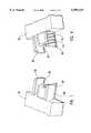
- a coaxial jackincludes a base having a front face. Projecting from the front face of the base it a tubular insulator made from a dielectric material. The tubular insulator encircles a conductive socket which in turn bounds an opening. The opening is configured to receive the contact pin of a conventional coaxial connector. Also projecting from the front face of the base on opposing sides of the insulator is a conductive first retention arm and a conductive second retention arm. Each of the retention arms has a curved inside face and an opposing curved outside face. In one embodiment, each outside face has a knob projecting therefrom.
- the outside facecan be smooth or have threads formed thereon.
- the retention armsare spaced from the tubular insulator so that a gap is formed therebetween.
- the retention arms, tubular insulator, and conductive socketare configured to be engaged with a conventional coaxial connector, such as a bayonet connector or BNC, in a conventional way.
- the coaxial jackcan be slidably disposed within a PC card or other electrical apparatus.
- the coaxial jackis operable between an extended position and a retracted position.
- the retention arms, tubular insulator, and conductive socketproject from the PC card or other electrical apparatus so that the coaxial connector can freely couple therewith.
- the coaxial jackIn the retracted position, the coaxial jack is substantially enclosed within the PC card or other electrical apparatus so as to be protected.
- the inventive coaxial jackhas a number of unique and beneficial features.
- the coaxial jackcan be mounted on a PC card so that a conventional coaxial connector can be directly coupled therewith without the use of a separate adapter.
- the coaxial jackcan be selectively retracted into the PC card so as to enable the PC card to maintain its required form factor.
- the inventive coaxial jackcan further be mounted directly onto an electrical apparatus such as a laptop computer, cellular telephone, or PIM to facilitate direct electrical communication with a coaxial cable.
- FIG. 1is perspective view of a computer having a PC card with an inventive coaxial jack projecting therefrom;
- FIG. 2is a front view of a coaxial connector shown in FIG. 1;
- FIG. 3is a partially cut away top view of the PC card shown in FIG. 1 with the inventive coaxial jack projecting therefrom;
- FIG. 4is an elevated partially cross sectional back view of the coaxial jack shown in FIG. 3;
- FIG. 5is an elevated side view of a channel formed on the PC card shown in FIG. 3;
- FIG. 6is an elevated front view of the coaxial jack shown in FIG. 3;
- FIG. 7is a perspective view of an alternative embodiment of the media jack shown in FIG. 3;
- FIG. 8is a perspective view of another alternative embodiment of the media jack shown in FIG. 3;
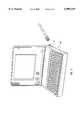
- FIG. 9is a perspective view of the inventive coaxial jack directly mounted onto a laptop computer.
- PC cardDepicted in FIG. 1 is a computer 10 housing a PC card 12.
- PC cardis broadly intended to include the various types of cards falling within the Personal Computer Memory Card International Association (PCMCIA) perimeters, communication cards falling outside of those standards, and cards which are developed under new standards. Examples of PC cards include modem cards, network cards, memory cards, SCSI cards, cellular phone cards, and combinations thereof. PC cards can have but are not limited to having a Type I, II, or III form factor.
- a retractable coaxial jack 14, in a preferred embodiment of the present invention,is attached to the PC card 12.
- the coaxial jack 14is configured to be physically and electrically coupled to a coaxial connector 16 attached to an end of a coaxial cable 18.
- coaxial connectoris broadly intended to include all the various types of connectors used with coaxial cables.
- a coaxial connectoras depicted in FIG. 1, is a bayonet connector or BNC.
- Other types of coaxial connectorsinclude RCA connectors and F-type connectors.
- Coaxial connector 16is mounted on a coaxial cable 18 but could equally be mounted on other conventional adapters designed for operation with a coaxial cable.
- coaxial connector 16comprises a tubular insulator 22 bounding a substantially cylindrical chamber 24. Concentrically disposed within chamber 24 is a metal contact pin 20. Encircling the exterior of insulator 22 is a conductive sleeve 26. Rotatably encircling sleeve 26 is an annular collar 28. Conductive sleeve 26 and collar 28 bound an annular space 27 therebetween. Formed on opposing sides of collar 28 are a pair of slots 30 and 31. As depicted in FIG. 1, each slot 30 and 31 includes a first section 32 that is axially aligned with coaxial connector 16 and a second section 34 that curves to partially spiral around coaxial connector 16.
- PC card 12comprises a housing 36 which includes a top cover plate 38 and an opposing bottom cover plate 40.
- a narrow boarder member 42secures plates 38 and 40 together around the perimeter thereof.
- Cover plates 38 and 40bound a compartment 44 therebetween in which a circuit board 46 is disposed.
- Formed at a front end 48 of PC card 12is an opening 50. Opening 50 extends through boarder member 42 to communicate with compartment 44.
- Coaxial jack 14is slidably positioned within compartment 44 so as to selectively move between an extended position and a retracted position. In the extended position, as shown in FIG. 3, a portion of coaxial jack 14 projects out of opening 50 for attachment with coaxial connector 16. When not in use, coaxial jack 14 can be selectively moved into the retracted position wherein coaxial jack 14 is substatially enclosed within compartment 44.
- the coaxial jack 14comprises a base 52 having opposing sides 54 and 58 extending between a front face 89 and an opposing back face 59.
- the side 54 of the coaxial jack 14slidably engages with a portion of the boarder member 42 and a stop 56 projects from the end of the jack.
- meansare provided for biasing base 52 outward into the extended position.
- a tubular tail 60projects from the end of side 58.
- tail 60has an opening 62 configured to receive a spring 64.
- Tail 60also includes a pair of inwardly facing finger 68 that slidably engage a rail 70 formed on boarder member 42.
- the opposing end of spring 64is mounted on a post 66 projecting off of border member 42. In this configuration, spring 64 functions to bias base 52 outward into the extended position.
- spring 64can be placed at different locations to bias against base 52.
- spring 64can be replaced with other conventional types of springs such as a leaf spring. Examples of alternative embodiments of the means for biasing base 52 outward are disclosed in U.S. Pat. No. 5,547,401, filed Aug. 16, 1994 (hereinafter “the '401 patent”), and U.S. patent application No. 08/976,819, filed Nov. 24, 1997 (hereinafter "the '819 application”), which are incorporated herein by specific reference.
- the present inventionalso includes means for selectively retaining base 52 in the retracted position.
- rail 70has a front face 72 with a channel 74 recessed therein.
- a substantially heart-shaped grove 76 having a substantially heart-shaped guide 78 disposed in the center thereofis formed at the end of channel 74.
- a flexible pin 80projects from base 52 into channel 74.
- pin 80travels along channel 74 into grove 76.
- pin 80travels in an upper side channel 82 which curves around to a first alcove 86.
- Alcove 86stops the progression of pin 80 and thus base 52.
- spring 64produces a biasing outward force on base 52 causing pin 80 to move into a saddle 87 formed on guide 78.
- the contact between pin 80 and saddle 87prevents base 52, which is continually urged by spring 64, from automatically advancing out into the extended position.
- base 52is manually pushed slightly into compartment 44.
- the configuration of grove 76causes pin 80 to move into an outwardly curving second alcove 88.
- pin 80slides down a lower side channel 91 back into main channel 74, thereby allowing base 52 to freely slide outward into the extended position.
- Alternative embodiments of the means for selectively retainingare disclosed in the '401 patent and '819 application which were previously incorporated herein by specific reference.
- the present inventionalso includes means projecting from base 52 for physically and electrically coupling with coaxial connector 16 when base 52 is in the extended position.
- a tubular insulator 90made from a dielectric material. Insulator 90 encircles a conductive socket 92. Socket 92 bounds an opening 94 configured to receive contact pin 20 of coaxial connector 16 in electrical contact.
- a conductive first retention arm 95 and a conductive second retention arm 96are also projecting from face 89 on opposing sides of insulator 90. In an alternative embodiment, only one of retention arms 95 and 96 needs to be conductive.
- Each retention arm 95 and 96has a curved inside face 98 and an opposing curved outside face 100. Each outside face 100 has a knob 102 projecting therefrom. Retention arms 95 and 96 are spaced from tubular insulator 90 so that a gap 104 is formed therebetween. Furthermore, each of retention arms 95 and 96 have a height H which in one embodiment does not exceed the thickness of PC card 12 and more preferably does not exceed the thickness of base 52.
- conductive socket 92is in electrical communication with a conductive line wire 102 extending through base 52.
- at least one of the conductive retention arms 95 and 96are in electrical communication with a conductive line wire 104 also extending through base 52.
- a flexible wire ribbon 108electrically connects line wires 102 and 104 with circuitry located on circuit board 46.
- coaxial connector 16is slid onto coaxial jack 14 such that: contact pin 20 is received within opening 94 of socket 92; retention arms 95, 96 are received within annular space 27 formed between conductive sleeve 26 and collar 28; and knobs 102 are received within opposing slots 30,31 on collar 28.
- collar 30is rotated a quarter turn, thereby locking coaxial connector 16 on coaxial jack 14.
- inventive coaxial jack 14can have a variety of different configurations.
- base 52need not have the substantially box shaped configuration as depicted in the above example. Rather, base 52 need only have the necessary structural elements to provide its function of supporting the other elements.
- base 52may be integrally formed with retention arms 95 and 96.
- retention arms 95 and 96can be separated or integrally bound together at the base of each arm and yet still be considered discrete arms.
- Retention arms 95 and 96can also be configured to couple with a variety of different types of coaxial connectors.
- retention arms 95 and 96can be formed with a smooth outside face 108.
- retention arms 95 and 96can each be formed with a curved outside face 110 having screw threads 112 formed thereon.
- insulator 90need not have a circular exterior surface. Rather in one embodiment, it may be necessary to flatten the top and bottom of insulator 90 so as to fit on a desired PC card.
- inventive coaxial jackneed not be incorporated onto a PC card. Rather, the inventive coaxial jack can be incorporated directly onto an electrical apparatus such as a laptop computer, PIM, cellular telephone, television, stereo, or other electrical apparatus containing a CPU.
- inventive coaxial jack 14is mounted directly onto a laptop computer 106 without the use of a PC card. Examples of how jacks can be directly mounted to electrical apparatus are disclosed in the '819 application which was previously incorporated herein by specific reference.
Landscapes
- Engineering & Computer Science (AREA)
- Theoretical Computer Science (AREA)
- Computer Hardware Design (AREA)
- Physics & Mathematics (AREA)
- General Engineering & Computer Science (AREA)
- Human Computer Interaction (AREA)
- General Physics & Mathematics (AREA)
- Mathematical Physics (AREA)
- Coupling Device And Connection With Printed Circuit (AREA)
Abstract
Description
Claims (22)
Priority Applications (1)
| Application Number | Priority Date | Filing Date | Title |
|---|---|---|---|
| US09/183,835US6099329A (en) | 1992-04-08 | 1998-10-30 | Retractable coaxial jack |
Applications Claiming Priority (7)
| Application Number | Priority Date | Filing Date | Title |
|---|---|---|---|
| US07/866,670US5183404A (en) | 1992-04-08 | 1992-04-08 | Systems for connection of physical/electrical media connectors to computer communications cards |
| US97425392A | 1992-11-10 | 1992-11-10 | |
| US08/040,656US5338210A (en) | 1992-04-08 | 1993-03-31 | Media connector interface for use with a PCMCIA-architecture communications card |
| US08/291,277US5547401A (en) | 1992-04-08 | 1994-08-16 | Media connector interface for use with a thin-architecture communications card |
| US08/689,715US5727972A (en) | 1992-04-08 | 1996-08-16 | Media connector interface for use with a thin-architecture communications card |
| US97681997A | 1997-11-24 | 1997-11-24 | |
| US09/183,835US6099329A (en) | 1992-04-08 | 1998-10-30 | Retractable coaxial jack |
Related Parent Applications (1)
| Application Number | Title | Priority Date | Filing Date |
|---|---|---|---|
| US97681997AContinuation-In-Part | 1992-04-08 | 1997-11-24 |
Publications (1)
| Publication Number | Publication Date |
|---|---|
| US6099329Atrue US6099329A (en) | 2000-08-08 |
Family
ID=46255231
Family Applications (1)
| Application Number | Title | Priority Date | Filing Date |
|---|---|---|---|
| US09/183,835Expired - LifetimeUS6099329A (en) | 1992-04-08 | 1998-10-30 | Retractable coaxial jack |
Country Status (1)
| Country | Link |
|---|---|
| US (1) | US6099329A (en) |
Cited By (14)
| Publication number | Priority date | Publication date | Assignee | Title |
|---|---|---|---|---|
| US6351388B1 (en)* | 1997-11-21 | 2002-02-26 | Xybernaut Corporation | Mobile computer with PC housing for PC card and dongle |
| US6424796B2 (en)* | 1998-07-21 | 2002-07-23 | Gateway, Inc. | Optical storage media drive adapter for stand-alone use |
| US6532147B1 (en)* | 1999-09-24 | 2003-03-11 | International Business Machines Corporation | Flexible monitor/display on mobile device |
| US20030075604A1 (en)* | 2000-09-19 | 2003-04-24 | International Business Machines Corporation | Connecting structure of card, card, and computer system |
| US6579108B1 (en) | 2001-10-17 | 2003-06-17 | 3Com Corporation | Retractable jack |
| DE10233075A1 (en)* | 2002-07-19 | 2004-02-12 | Phoenix Contact Gmbh & Co. Kg | Electrical in line plug and socket connector has a threaded coupling with part of the thread cut away on sectors to allow full axial engagement before locking the parts together |
| EP1524732A1 (en)* | 2003-10-18 | 2005-04-20 | Phoenix Contact GmbH & Co. KG | Electrical connector |
| US20050118853A1 (en)* | 2003-11-12 | 2005-06-02 | Phoenix Contact Gmbh & Co. Kg | Electrical connector |
| US20050250365A1 (en)* | 2002-07-19 | 2005-11-10 | Phoenix Contact Gmbh & Co. Kg | Electrical connector |
| US20060114160A1 (en)* | 2004-11-29 | 2006-06-01 | Lexmark International, Inc. | Snap-in antenna assembly for wireless radio circuit card |
| US20070117477A1 (en)* | 2005-11-21 | 2007-05-24 | Manfred Ege | Electrical network-powered hand-held power tool |
| GB2433845A (en)* | 2005-12-29 | 2007-07-04 | Motorola Inc | Computer with retractable socket |
| US20090088018A1 (en)* | 2007-09-28 | 2009-04-02 | Marcell Nickol | Connector for electrical and optical cables |
| US20120329332A1 (en)* | 2011-06-21 | 2012-12-27 | Lai Yen-Chang | Plug assembly adapted to an adapter and a computer device |
Citations (23)
| Publication number | Priority date | Publication date | Assignee | Title |
|---|---|---|---|---|
| US363568A (en)* | 1887-05-24 | Incandescent-lamp fixture | ||
| US879773A (en)* | 1906-01-12 | 1908-02-18 | Benjamin Electric Mfg Co | Extension-plug for electric lights. |
| US1504843A (en)* | 1921-04-04 | 1924-08-12 | William E Shore | Electrical plug connecter |
| US2877437A (en)* | 1955-10-19 | 1959-03-10 | United Carr Fastener Corp | Connector |
| US3173473A (en)* | 1962-06-08 | 1965-03-16 | Honeywell Inc | Thermocouple clip |
| US4138182A (en)* | 1977-06-16 | 1979-02-06 | Trio Kabushiki Kaisha | Pin type jack-and-plug coupling device |
| US4836801A (en)* | 1987-01-29 | 1989-06-06 | Lucas Weinschel, Inc. | Multiple use electrical connector having planar exposed surface |
| US5139439A (en)* | 1991-07-16 | 1992-08-18 | Veridata Electronics Inc. | Portable computer with detachable cartridge type interface device |
| US5183404A (en)* | 1992-04-08 | 1993-02-02 | Megahertz Corporation | Systems for connection of physical/electrical media connectors to computer communications cards |
| US5411405A (en)* | 1993-11-12 | 1995-05-02 | Angia Communications, Inc. | Miniature electrical communications connectors |
| US5439394A (en)* | 1993-04-23 | 1995-08-08 | Hirose Electric Co., Ltd. | Electric connector with a coaxial connector |
| US5463261A (en)* | 1994-10-19 | 1995-10-31 | Minnesota Mining And Manufacturing Company | Power conservation device for a peripheral interface module |
| US5474470A (en)* | 1994-03-30 | 1995-12-12 | Itt Corporation | Compensated interface coaxial connector apparatus |
| US5499923A (en)* | 1994-11-09 | 1996-03-19 | At&T Corp. | Communication card with extendible, rotatable coupling |
| US5505633A (en)* | 1994-05-13 | 1996-04-09 | Intel Corporation | Integral external connector interface for thin form factor computer cards |
| US5538442A (en)* | 1993-10-04 | 1996-07-23 | Murata Mfg. Co., Ltd. | Communication card |
| US5561727A (en)* | 1994-02-15 | 1996-10-01 | Sumitomo Electric Industries, Ltd. | Card-shaped optical data link device |
| US5608607A (en)* | 1995-04-24 | 1997-03-04 | Compaq Computer Corporation | PCMCIA card and associated support and circuitry augmenting apparatus and methods |
| US5634802A (en)* | 1994-08-18 | 1997-06-03 | International Business Machines Corporation | Retractable expandable jack |
| US5660568A (en)* | 1995-01-04 | 1997-08-26 | Simple Technology, Inc. | Communications card with integral transmission media line adaptor |
| US5679013A (en)* | 1994-11-14 | 1997-10-21 | International Business Machines Corporation | Electrical connector and an electronic apparatus using the electrical connector |
| US5773332A (en)* | 1993-11-12 | 1998-06-30 | Xircom, Inc. | Adaptable communications connectors |
| US5928009A (en)* | 1996-08-23 | 1999-07-27 | Samsung Electronics Co., Ltd. | Communications card capable of directly connecting to a BNC |
- 1998
- 1998-10-30USUS09/183,835patent/US6099329A/ennot_activeExpired - Lifetime
Patent Citations (24)
| Publication number | Priority date | Publication date | Assignee | Title |
|---|---|---|---|---|
| US363568A (en)* | 1887-05-24 | Incandescent-lamp fixture | ||
| US879773A (en)* | 1906-01-12 | 1908-02-18 | Benjamin Electric Mfg Co | Extension-plug for electric lights. |
| US1504843A (en)* | 1921-04-04 | 1924-08-12 | William E Shore | Electrical plug connecter |
| US2877437A (en)* | 1955-10-19 | 1959-03-10 | United Carr Fastener Corp | Connector |
| US3173473A (en)* | 1962-06-08 | 1965-03-16 | Honeywell Inc | Thermocouple clip |
| US4138182A (en)* | 1977-06-16 | 1979-02-06 | Trio Kabushiki Kaisha | Pin type jack-and-plug coupling device |
| US4836801A (en)* | 1987-01-29 | 1989-06-06 | Lucas Weinschel, Inc. | Multiple use electrical connector having planar exposed surface |
| US5139439A (en)* | 1991-07-16 | 1992-08-18 | Veridata Electronics Inc. | Portable computer with detachable cartridge type interface device |
| US5183404A (en)* | 1992-04-08 | 1993-02-02 | Megahertz Corporation | Systems for connection of physical/electrical media connectors to computer communications cards |
| US5439394A (en)* | 1993-04-23 | 1995-08-08 | Hirose Electric Co., Ltd. | Electric connector with a coaxial connector |
| US5538442A (en)* | 1993-10-04 | 1996-07-23 | Murata Mfg. Co., Ltd. | Communication card |
| WO1995013633A1 (en)* | 1993-11-12 | 1995-05-18 | Angia Communications, Inc. | Adaptable communications connectors |
| US5411405A (en)* | 1993-11-12 | 1995-05-02 | Angia Communications, Inc. | Miniature electrical communications connectors |
| US5773332A (en)* | 1993-11-12 | 1998-06-30 | Xircom, Inc. | Adaptable communications connectors |
| US5561727A (en)* | 1994-02-15 | 1996-10-01 | Sumitomo Electric Industries, Ltd. | Card-shaped optical data link device |
| US5474470A (en)* | 1994-03-30 | 1995-12-12 | Itt Corporation | Compensated interface coaxial connector apparatus |
| US5505633A (en)* | 1994-05-13 | 1996-04-09 | Intel Corporation | Integral external connector interface for thin form factor computer cards |
| US5634802A (en)* | 1994-08-18 | 1997-06-03 | International Business Machines Corporation | Retractable expandable jack |
| US5463261A (en)* | 1994-10-19 | 1995-10-31 | Minnesota Mining And Manufacturing Company | Power conservation device for a peripheral interface module |
| US5499923A (en)* | 1994-11-09 | 1996-03-19 | At&T Corp. | Communication card with extendible, rotatable coupling |
| US5679013A (en)* | 1994-11-14 | 1997-10-21 | International Business Machines Corporation | Electrical connector and an electronic apparatus using the electrical connector |
| US5660568A (en)* | 1995-01-04 | 1997-08-26 | Simple Technology, Inc. | Communications card with integral transmission media line adaptor |
| US5608607A (en)* | 1995-04-24 | 1997-03-04 | Compaq Computer Corporation | PCMCIA card and associated support and circuitry augmenting apparatus and methods |
| US5928009A (en)* | 1996-08-23 | 1999-07-27 | Samsung Electronics Co., Ltd. | Communications card capable of directly connecting to a BNC |
Cited By (25)
| Publication number | Priority date | Publication date | Assignee | Title |
|---|---|---|---|---|
| US6351388B1 (en)* | 1997-11-21 | 2002-02-26 | Xybernaut Corporation | Mobile computer with PC housing for PC card and dongle |
| US6424796B2 (en)* | 1998-07-21 | 2002-07-23 | Gateway, Inc. | Optical storage media drive adapter for stand-alone use |
| US6532147B1 (en)* | 1999-09-24 | 2003-03-11 | International Business Machines Corporation | Flexible monitor/display on mobile device |
| US6786409B2 (en)* | 2000-09-19 | 2004-09-07 | International Business Machines Corporation | Connecting structure of card, card, and computer system |
| US20030075604A1 (en)* | 2000-09-19 | 2003-04-24 | International Business Machines Corporation | Connecting structure of card, card, and computer system |
| US6942149B2 (en) | 2000-09-19 | 2005-09-13 | International Business Machines Corporation | Connecting structure of card, card, and computer system |
| US6579108B1 (en) | 2001-10-17 | 2003-06-17 | 3Com Corporation | Retractable jack |
| US20050250365A1 (en)* | 2002-07-19 | 2005-11-10 | Phoenix Contact Gmbh & Co. Kg | Electrical connector |
| DE10233075B4 (en)* | 2002-07-19 | 2004-07-22 | Phoenix Contact Gmbh & Co. Kg | Electrical connector |
| DE10233075A1 (en)* | 2002-07-19 | 2004-02-12 | Phoenix Contact Gmbh & Co. Kg | Electrical in line plug and socket connector has a threaded coupling with part of the thread cut away on sectors to allow full axial engagement before locking the parts together |
| US7874860B2 (en) | 2002-07-19 | 2011-01-25 | Phoenix Contact Gmbh & Co. Kg | Electrical connector |
| EP1524732A1 (en)* | 2003-10-18 | 2005-04-20 | Phoenix Contact GmbH & Co. KG | Electrical connector |
| US20050118853A1 (en)* | 2003-11-12 | 2005-06-02 | Phoenix Contact Gmbh & Co. Kg | Electrical connector |
| US6957972B2 (en) | 2003-11-12 | 2005-10-25 | Phoenix Contact Gmbh | Electrical connector |
| US20060114160A1 (en)* | 2004-11-29 | 2006-06-01 | Lexmark International, Inc. | Snap-in antenna assembly for wireless radio circuit card |
| US7262735B2 (en) | 2004-11-29 | 2007-08-28 | Lexmark International, Inc. | Snap-in antenna assembly for wireless radio circuit card |
| US7320620B2 (en)* | 2005-11-21 | 2008-01-22 | Hilti Aktiengesellschaft | Electrical network-powered hand-held power tool |
| US20070117477A1 (en)* | 2005-11-21 | 2007-05-24 | Manfred Ege | Electrical network-powered hand-held power tool |
| US20070155203A1 (en)* | 2005-12-29 | 2007-07-05 | Motorola, Inc. | Computing device and socket protection mechanism therefor |
| US7410371B2 (en) | 2005-12-29 | 2008-08-12 | Motorola, Inc. | Computing device having socket and accessory device containment |
| GB2433845A (en)* | 2005-12-29 | 2007-07-04 | Motorola Inc | Computer with retractable socket |
| US20090088018A1 (en)* | 2007-09-28 | 2009-04-02 | Marcell Nickol | Connector for electrical and optical cables |
| US7575459B2 (en)* | 2007-09-28 | 2009-08-18 | Weidmuller Interface Gmbh & Co. Kg | Connector for electrical and optical cables |
| US20120329332A1 (en)* | 2011-06-21 | 2012-12-27 | Lai Yen-Chang | Plug assembly adapted to an adapter and a computer device |
| US8499183B2 (en)* | 2011-06-21 | 2013-07-30 | Wistron Corporation | Plug assembly adapted to an adapter and a computer device |
Similar Documents
| Publication | Publication Date | Title |
|---|---|---|
| US6099329A (en) | Retractable coaxial jack | |
| US5885088A (en) | Electrical connector assembly with polarization means | |
| US5989042A (en) | Electrical connector for use between shielded media connectors and computer communications cards | |
| US7306484B1 (en) | Coax-to-power adapter | |
| US5336099A (en) | Media connector interface for use with a PCMCIA-architecture communications card | |
| US5440315A (en) | Antenna apparatus for capacitively coupling an antenna ground plane to a moveable antenna | |
| US4989012A (en) | Antenna assembly | |
| US5816832A (en) | Media connector interface for use with a PCMCIA-architecture communications card | |
| US5803757A (en) | Auto-termination single jack BNC connector | |
| US4971569A (en) | Self-terminating coaxial tap connector | |
| US5951317A (en) | Accessory connector assembly | |
| US6033240A (en) | Retractable media jack operable with two discrete media connectors | |
| US6045393A (en) | Foldable connector assembly for miniature circuit card | |
| EP0601702A1 (en) | Internal/external antenna switch connector | |
| CN100508277C (en) | Retractable Antennas for PC Cards | |
| JP2001512893A (en) | Electrical connector device attachable to surface | |
| US5562463A (en) | I/O card with flexible extending I/O port | |
| US5975927A (en) | Communications card having rotating communications port | |
| US6942149B2 (en) | Connecting structure of card, card, and computer system | |
| JPH05182726A (en) | Stack type orientation independent type electric connector | |
| US6190210B1 (en) | Low profile modular jack | |
| US6287133B1 (en) | Dustproof cover | |
| US6579108B1 (en) | Retractable jack | |
| US6019630A (en) | Foldable connector assembly for miniature circuit card | |
| US6102714A (en) | Electrical connectors having dual biased contact pins |
Legal Events
| Date | Code | Title | Description |
|---|---|---|---|
| AS | Assignment | Owner name:3COM CORPORATION, CALIFORNIA Free format text:ASSIGNMENT OF ASSIGNORS INTEREST;ASSIGNORS:GOFF, DARRELL E.;ALDOUS, STEPHEN C.;REEL/FRAME:009576/0720 Effective date:19981029 | |
| STCF | Information on status: patent grant | Free format text:PATENTED CASE | |
| FPAY | Fee payment | Year of fee payment:4 | |
| FEPP | Fee payment procedure | Free format text:PAYOR NUMBER ASSIGNED (ORIGINAL EVENT CODE: ASPN); ENTITY STATUS OF PATENT OWNER: LARGE ENTITY | |
| FPAY | Fee payment | Year of fee payment:8 | |
| AS | Assignment | Owner name:HEWLETT-PACKARD COMPANY, CALIFORNIA Free format text:MERGER;ASSIGNOR:3COM CORPORATION;REEL/FRAME:024630/0820 Effective date:20100428 | |
| AS | Assignment | Owner name:HEWLETT-PACKARD COMPANY, CALIFORNIA Free format text:CORRECTIVE ASSIGNMENT TO CORRECT THE SEE ATTACHED;ASSIGNOR:3COM CORPORATION;REEL/FRAME:025039/0844 Effective date:20100428 | |
| FPAY | Fee payment | Year of fee payment:12 | |
| AS | Assignment | Owner name:HEWLETT-PACKARD DEVELOPMENT COMPANY, L.P., TEXAS Free format text:ASSIGNMENT OF ASSIGNORS INTEREST;ASSIGNOR:HEWLETT-PACKARD COMPANY;REEL/FRAME:027329/0044 Effective date:20030131 | |
| AS | Assignment | Owner name:HEWLETT-PACKARD DEVELOPMENT COMPANY, L.P., TEXAS Free format text:CORRECTIVE ASSIGNMENT PREVIUOSLY RECORDED ON REEL 027329 FRAME 0001 AND 0044;ASSIGNOR:HEWLETT-PACKARD COMPANY;REEL/FRAME:028911/0846 Effective date:20111010 |