US6099311A - Abutment delivery system - Google Patents
Abutment delivery systemDownload PDFInfo
- Publication number
- US6099311A US6099311AUS09/362,620US36262099AUS6099311AUS 6099311 AUS6099311 AUS 6099311AUS 36262099 AUS36262099 AUS 36262099AUS 6099311 AUS6099311 AUS 6099311A
- Authority
- US
- United States
- Prior art keywords
- tool
- portions
- retainer
- implant
- components
- Prior art date
- Legal status (The legal status is an assumption and is not a legal conclusion. Google has not performed a legal analysis and makes no representation as to the accuracy of the status listed.)
- Expired - Fee Related
Links
- 239000007943implantSubstances0.000claimsabstractdescription61
- 239000004053dental implantSubstances0.000claimsabstractdescription30
- 238000003780insertionMethods0.000claimsabstractdescription6
- 230000037431insertionEffects0.000claimsabstractdescription6
- 238000000034methodMethods0.000claimsdescription9
- 239000000463materialSubstances0.000claimsdescription6
- 230000001788irregularEffects0.000claimsdescription5
- 210000000078clawAnatomy0.000claimsdescription2
- 229920002994synthetic fiberPolymers0.000claims3
- 210000000988bone and boneAnatomy0.000description3
- 230000035876healingEffects0.000description2
- 230000014759maintenance of locationEffects0.000description2
- 238000004806packaging method and processMethods0.000description2
- 238000005553drillingMethods0.000description1
- 238000002513implantationMethods0.000description1
- 230000013011matingEffects0.000description1
- 230000004048modificationEffects0.000description1
- 238000012986modificationMethods0.000description1
- 229920000642polymerPolymers0.000description1
- 238000002360preparation methodMethods0.000description1
- 230000000750progressive effectEffects0.000description1
- 238000004513sizingMethods0.000description1
- 210000004872soft tissueAnatomy0.000description1
- 238000004659sterilization and disinfectionMethods0.000description1
- 238000006467substitution reactionMethods0.000description1
Images


Classifications
- A—HUMAN NECESSITIES
- A61—MEDICAL OR VETERINARY SCIENCE; HYGIENE
- A61C—DENTISTRY; APPARATUS OR METHODS FOR ORAL OR DENTAL HYGIENE
- A61C8/00—Means to be fixed to the jaw-bone for consolidating natural teeth or for fixing dental prostheses thereon; Dental implants; Implanting tools
- A61C8/0087—Means for sterile storage or manipulation of dental implants
- A—HUMAN NECESSITIES
- A61—MEDICAL OR VETERINARY SCIENCE; HYGIENE
- A61C—DENTISTRY; APPARATUS OR METHODS FOR ORAL OR DENTAL HYGIENE
- A61C8/00—Means to be fixed to the jaw-bone for consolidating natural teeth or for fixing dental prostheses thereon; Dental implants; Implanting tools
- A61C8/0089—Implanting tools or instruments
Definitions
- the disclosures hereinrelated generally to dental implants and more particularly to a tool for retaining and delivering implant components to a dental implant at an implant site.
- the surgical process of dental implant placementincludes a bone preparation process including an incision to expose that portion of bone to receive the implant. Progressive drilling and alignment procedures prepare an implant bed in the bone for proper implant sizing and implant placement. The incision is closed and a healing period follows.
- the top of the implantis exposed and a temporary gingival cuff is attached to the implant for the purpose of contouring the surrounding soft tissue to coincide with the implant components to be subsequently attached to the implant.
- U.S. Pat. No. 5,105,690discloses a driver for screws, bolts and the like which have a socket for receiving the bit of a driver, in which a tapered holding section between the bit and the shaft of the drivers serves to hold an article by frictional engagement with the opening edge of the socket when the bit is engaged in the socket for turning the article.
- the bitis shorter than the depth of the socket, and the holding section expands sufficiently away from the bit so as to make frictional contact with the edge of the socket when the bit is engaged in the socket.
- U.S. Pat. No., 5,690,489discloses a self-locking cylindrical driver to deliver and assemble internally hexed prosthetic components such as screws and abutments into place.
- the head of the toolengages and locks with the flat side surfaces of the internally hexed prosthetic component.
- the toolallows for extra-oral assembly of a component with the tool to minimize any risk of a component falling off or being lost in a patient's mouth during delivery of the component.
- Final seating of the componentis then accomplished using a conventional hexagonal drive tool with appropriate delivery torque.
- the toolis formed into both a standard hand driven wrench and a contra-angle drill.
- U.S. Pat. No. 5,437,550discloses a tool for affixing a component to a dental implant fixture with a screw passing through the component and threaded into the implant fixture.
- the toolhas two parts telescopically interfitting one within the other, the outer part being tubular for carrying the component at one end, and the inner part fitted at one end for carrying the screw positioned within the component.
- the component, and the screw within itcan be carried together to the implant fixture where the outer part is used to hold the component in place while the inner part is used to drive the screw into the implant fixture.
- a limitation of previous delivery systemsis that the various implant components cannot all be delivered and attached by a single versatile tool. Therefore, what is needed is a versatile tool which can engage, retain, deliver and at least initially engage the various components with the implant.
- a tool for retaining and delivering dental implant componentsincludes a retainer member having a delivery end which includes a plurality of concentric, various sized retainer portions.
- various implant componentscan be sequentially or simultaneously frictionally engaged by the implant tool for delivery to the implant site.
- the toolcan be immediately removed or used to manipulate the component to cause initial engagement with the implant and then be subsequently removed.
- a handlemay be pivotally attached to the tool if desired by a snap-in, snap-out feature. With the handle detached, an auxiliary drive tool can engage the implant tool for further manipulation of the component into engagement with the implant.
- the toolenables component removal from sterile packaging for delivery directly to the implant site so as to avoid improper or non-sterile handling.
- the toolis sized to be smaller than the component being delivered for facilitated access to space limited implant sites.
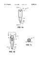
- FIG. 1ais a side view illustrating an embodiment of a tool for retaining and delivering dental implant components.
- FIG. 1bis a cross-sectional view taken along line 1b--1b of FIG. 1a.
- FIG. 1cis an end view taken along line 1c--1c of FIG. 1b.
- FIG. 2is an isometric view illustrating another embodiment of the tool attached to a handle.
- FIG. 3ais an isometric view illustrating another embodiment of the tool attached to a handle.
- FIG. 3bis an end view taken along line 3b--3b of FIG. 3a.
- FIG. 4is an isometric view illustrating another embodiment of the tool attached to a handle.
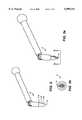
- FIG. 5ais an isometric view illustrating an embodiment of the tool including a ball connected to a socket of a handle.
- FIG. 5bis a cross-sectional view taken along line 5b--5b of FIG. 5a.
- FIG. 6ais an isometric view illustrating an embodiment of the tool including a socket connected to a ball of a handle.
- FIG. 6bis a cross-sectional view taken along the line 6b--6b of FIG. 6a.
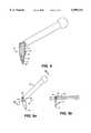
- FIG. 7a-7eillustrate embodiments of various connectors for the tool and the handle.
- FIG. 8ais an isometric view illustrating an embodiment of a hex drive seating tool.
- FIG. 8bis an end view taken along line 8b--8b of FIG. 8a.
- FIG. 9ais a side view illustrating another embodiment of a tool for retaining and delivering dental implant components.
- FIG. 9bis a cross-sectional view taken along line 9b--9b of FIG. 9a.
- FIG. 9cis an end view taken along line 9c--9c of FIG. 9b.
- FIG. 10a and 10billustrate an embodiment of the tool and handle connected for delivering a threaded fastener.
- FIG. 1a and 11billustrate an embodiment of the tool and handle connected for delivering a shouldered abutment.
- FIG. 12a and 12billustrate an embodiment of the tool and handle connected for delivering a fixed abutment.
- FIG. 13a and 13billustrate an embodiment of the tool and handle connected for delivering a temporary gingival cuff.
- FIG. 14a and 14billustrate an embodiment of the tool and handle connected for simultaneously delivering a threaded fastener and a fixed abutment.
- a tool 10, FIGS. 1a, 1b and 1c,is provided for retaining and delivering dental implant components.
- the tool 10includes a retainer or post member which has a main body portion 12 and opposite ends 14 and 16.
- One endis a delivery end 14 and includes a plurality of concentric, various sized portions 14a, 14b and 14c.
- Each of the portions 14a, 14b and 14cis smaller in cross-section, sequentially, in a direction D1 extending toward the delivery end 14.
- the entire delivery end 14may be formed as a tapered member 114, FIG. 2, and portions 114a, 114b and 114c of the tapered member 114 are sized for insertion into various sized dental implant components, to be discussed below.
- the portions 14a, 14b and 14c, FIG. 1aare formed as stepped down portions, and at least one of the portions 14b is tapered.
- the tool 10is formed of a synthetic resilient, flexible material such as a polymer and may include a split 18, FIGS. 3a and 3b, in at least one of the portions, or may include an irregular surface 20, FIG. 4, including ribs 22, for example.
- the taper, the steps, the flexible material, the split and the irregular surfaceall contribute to the delivery end providing a frictional engagement with various dental implant components.
- the tool 10, FIGS. 5a and 5bincludes a connector at the other or connection end 16 opposite the delivery end 14.
- the connectorprovides for attachment of the tool 10 to an extension member such as a handle 26.
- Thismay be accomplished by providing a snap-in, snap-out connection in a quick connect, quick disconnect manner.
- a preferred type of connection which may be usedis a ball and socket connection. This may be accomplished by providing a ball 24 at the connection end 16 of the tool 10 and providing a socket 28 at a connection end 30 of the handle 26.
- a socket 32, FIGS. 6a and 6bmay be provided at the connection end 16 of the tool 10 for engagement with a ball 34 provided at the connection 30 end of the handle 26.
- connections for connecting the tool 10 and the handle 26may include a claw and post connection 36, FIG. 7a, an integrally formed flexible joint 38, FIG. 7b, a hook and eye connection 40, FIG. 7c, a pinned connection 42, FIG. 7d, and a U-joint connection 44, FIG. 7e, each of which provide a movable, flexible, pivotal connection between the tool 10 and the handle 26.
- Forming the socket 32, FIG. 1b, in the connection end 16 of the tool 10also permits the additional feature of forming an engagement member 46 or receiver adjacent the socket 32 for receiving a male hex-drive seating tool 48, FIGS. 8a and 8b.
- FIG. 1bis formed as a female socket having a cross-section formed as a polygon, i.e. hexagonal, FIG. 1c, for receiving the male hex-drive seating tool 48, FIGS. 8a and 8b, having a mating hex cross-section 50 formed on a shaft 52 which extends from a handle 54, provided for turning the shaft 52.
- a hexagonal socket 56may be formed in the ball 24 for engagement with the hex-drive seating tool 48.
- Various dental implant componentsmay be sequentially fictionally engaged by the various portions of the delivery end of the tool.
- such componentsmay include a threaded fastener 58, FIGS. 10a and 10b, a shouldered abutment 60, FIGS. 11a and 11b, a fixed abutment 62, FIGS. 12a and 12b, a gingival cuff, 64, FIGS. 13a and 13b and simultaneous engagement of two of the delivery end portions 14c and 14b, FIGS. 14a and 14b, with the fixed abutment 62 and the threaded fastener 58, respectively.
- a portion of the delivery end 14is inserted into the component or components.
- one embodimentprovides a tool for retaining and delivering dental implant components including a retainer member having a delivery end which includes a plurality of concentric, various sized retainer portions.
- Another embodimentprovides a device for retaining and delivering dental implant components including a post member having a delivery end including a plurality of concentric, various sized portions. Each portion is smaller in cross-section sequentially in a direction extending toward the delivery end. Also, each portion is of a size sufficient for insertion into a receiver in the dental implant component.
- Still another embodimentprovides a dental implant component retainer and delivery device including a first member having a first end and a second end.
- a second memberis movably connected to the first end of the first member.
- the second end of the first memberincludes a plurality of concentric multi-sized portions, each portion being smaller in cross-section in a direction extending toward the second end.
- a further embodimentprovides a method of retaining and delivering dental implant components.
- a retainer memberis formed having a plurality of concentric multi-sized portions at a terminal end thereof.
- Various implant componentsare attached to selected ones of the multi-sized portions.
- the various componentsare delivered to a dental implant.
- the retainer memberis removed from the component after delivery.
- a still further embodimentprovides a device for retaining and delivering implant components including a post member having a multi-sized delivery end.
- the delivery endincludes a plurality of portions of sequentially smaller cross-section for hands-off insertion into, and frictional engagement with, various dental implant components.
- various implant componentscan be sequentially or simultaneously frictionally engaged by the implant tool for delivery to the implant site.
- the toolcan be immediately removed or used to manipulate the component to cause initial engagement with the implant and then be subsequently removed.
- a handlemay be pivotally attached to the tool if desired by a snap-in, snap-out feature. With the handle detached, an auxiliary drive tool can engage the implant tool for further manipulation of the component into engagement with the implant.
- the toolenables hands-off component removal from sterile packaging for delivery directly to the implant site so as to avoid improper or non-sterile handling.
- the toolis sized to be smaller than the component being delivered for facilitated access to space limited implant sites.
- the multiple stepped delivery end of FIG. 1ais replaced by a continuously tapered end.
- the toolretains implant components by means of a friction fit with a receiving feature formed in each implant component.
- the taperis designed so that the diameters necessary to create a friction fit with different types of implant components, occur at some point along its length.
- this embodimentincludes a pivoting handle that removably attaches to the tool and a keyed bore for receiving, for example, the hex drive delivery tool.
- the tapered embodimentis used exactly like the stepped tool.
- the componentis fit on the frictionally engaging portion of the delivery end.
- the componentis then delivered to the implant.
- the toolcan then be immediately removed or first used to manipulate the component to cause initial engagement with the implant and then removed. If insufficient room exists to rotate the tool with the handle attached, the handle can be removed and the delivery end can be manually rotated as a stand-alone unit or by using a second tool such as the hex drive delivery tool.
- the delivery toolhas a split delivery end.
- the splitcauses the delivery end to compress.
- the resilience of the material, coupled with the space provided by the splitthen causes the sides of the delivery end to frictionally engage the implant component.
- the geometry of the delivery endbecomes tapered allowing the tool to be wedged into the implant component.
- the delivery toolhas ribs that protrude from the stepped delivery portion.
- the ribsdeform when the tool is inserted into the implant component.
- the addition of ribsmay increase the strength of the friction engagement and increase the torque that can be applied before slipping occurs.
- the ribs on the main body portion of the delivery end, located immediately above the stepped portions,serve to aid in gripping the tool when the delivery end is manually rotated separate from the handle.
Landscapes
- Health & Medical Sciences (AREA)
- Oral & Maxillofacial Surgery (AREA)
- Orthopedic Medicine & Surgery (AREA)
- Dentistry (AREA)
- Epidemiology (AREA)
- Life Sciences & Earth Sciences (AREA)
- Animal Behavior & Ethology (AREA)
- General Health & Medical Sciences (AREA)
- Public Health (AREA)
- Veterinary Medicine (AREA)
- Dental Prosthetics (AREA)
Abstract
Description
Claims (35)
Priority Applications (1)
| Application Number | Priority Date | Filing Date | Title |
|---|---|---|---|
| US09/362,620US6099311A (en) | 1999-07-28 | 1999-07-28 | Abutment delivery system |
Applications Claiming Priority (1)
| Application Number | Priority Date | Filing Date | Title |
|---|---|---|---|
| US09/362,620US6099311A (en) | 1999-07-28 | 1999-07-28 | Abutment delivery system |
Publications (1)
| Publication Number | Publication Date |
|---|---|
| US6099311Atrue US6099311A (en) | 2000-08-08 |
Family
ID=23426831
Family Applications (1)
| Application Number | Title | Priority Date | Filing Date |
|---|---|---|---|
| US09/362,620Expired - Fee RelatedUS6099311A (en) | 1999-07-28 | 1999-07-28 | Abutment delivery system |
Country Status (1)
| Country | Link |
|---|---|
| US (1) | US6099311A (en) |
Cited By (45)
| Publication number | Priority date | Publication date | Assignee | Title |
|---|---|---|---|---|
| US6619958B2 (en)* | 1997-04-09 | 2003-09-16 | Implant Innovations, Inc. | Implant delivery system |
| US20040259051A1 (en)* | 2001-12-28 | 2004-12-23 | Nobel Biocare Ab | Arrangement and device for using a template to form holes for implants in bone, preferably jaw bone |
| US20060008763A1 (en)* | 2002-12-30 | 2006-01-12 | Izidor Brajnovic | Device and arrangement for fixture installation |
| WO2006014130A1 (en)* | 2004-08-05 | 2006-02-09 | Nobel Biocare Ab (Publ) | Guide device able to interact with a number of sleeves disposed in a tooth template |
| US20060064102A1 (en)* | 2002-09-23 | 2006-03-23 | Ebner Peter R | Apparatus and method for harvesting bone |
| US20060269890A1 (en)* | 2005-03-08 | 2006-11-30 | Ulrich Mundwiler | Holding element for a dental implant |
| US20070037121A1 (en)* | 2005-08-10 | 2007-02-15 | Carter Robert D | Carry and drive device and method for dental implant and/or components thereof |
| US20080038692A1 (en)* | 2003-12-10 | 2008-02-14 | Matts Andersson | System and Arrangement for Production and Insertion of a Dental Bridge Structure |
| US20080118895A1 (en)* | 2004-08-05 | 2008-05-22 | Nobel Biocare Services Ab | Device and Procedure for Facilitating the Fitting of a Tooth or Tooth Remnant Template Into the Right Position |
| US20080153065A1 (en)* | 2002-12-30 | 2008-06-26 | Nobel Biocare Ag | Device forming part of a dental screwing arrangement |
| US20100018359A1 (en)* | 2008-07-24 | 2010-01-28 | Dionex Corporation | Tight-spot fitting and driver, and method of use thereof |
| US20100035206A1 (en)* | 2007-08-17 | 2010-02-11 | Buttacavoli Joseph P | Dental tool for the fitting, installation and replacement of a dental prosthetic attachment |
| USD619152S1 (en) | 2009-12-18 | 2010-07-06 | Techtronic Power Tools Technology Limited | Adapter |
| USD623034S1 (en)* | 2009-12-18 | 2010-09-07 | Techtronic Power Tools Technology Limited | Tool arbor |
| US20110008751A1 (en)* | 2007-01-10 | 2011-01-13 | Nobel Biocare Services Ag | Method and system for dental planning and production |
| US8011927B2 (en) | 2008-04-16 | 2011-09-06 | Biomet 3I, Llc | Method for pre-operative visualization of instrumentation used with a surgical guide for dental implant placement |
| USD646542S1 (en) | 2010-09-29 | 2011-10-11 | Milwaukee Electric Tool Corporation | Accessory interface for a tool |
| USD651062S1 (en) | 2010-09-29 | 2011-12-27 | Milwaukee Electric Tool Corporation | Tool interface for an accessory |
| USD653523S1 (en) | 2010-09-29 | 2012-02-07 | Milwaukee Electric Tool Corporation | Adapter for a tool |
| US8185224B2 (en) | 2005-06-30 | 2012-05-22 | Biomet 3I, Llc | Method for manufacturing dental implant components |
| US8206153B2 (en) | 2007-05-18 | 2012-06-26 | Biomet 3I, Inc. | Method for selecting implant components |
| USRE43584E1 (en) | 2000-12-29 | 2012-08-14 | Nobel Biocare Services Ag | Method, arrangement and program for a prosthetic installation |
| US8257083B2 (en) | 2005-10-24 | 2012-09-04 | Biomet 3I, Llc | Methods for placing an implant analog in a physical model of the patient's mouth |
| US20130108987A1 (en)* | 2010-06-10 | 2013-05-02 | Straumann Holding Ag | Analog positioner |
| US8540510B2 (en) | 2006-05-04 | 2013-09-24 | Nobel Biocare Services Ag | Device for securing a dental implant in bone tissue, a method for making a surgical template and a method of securing a dental implant in bone tissue |
| US8636511B2 (en) | 2002-11-13 | 2014-01-28 | Biomet 3I, Llc | Dental implant system |
| US8651858B2 (en) | 2008-04-15 | 2014-02-18 | Biomet 3I, Llc | Method of creating an accurate bone and soft-tissue digital dental model |
| US8777612B2 (en) | 2007-11-16 | 2014-07-15 | Biomet 3I, Llc | Components for use with a surgical guide for dental implant placement |
| US8882508B2 (en) | 2010-12-07 | 2014-11-11 | Biomet 3I, Llc | Universal scanning member for use on dental implant and dental implant analogs |
| US8926328B2 (en) | 2012-12-27 | 2015-01-06 | Biomet 3I, Llc | Jigs for placing dental implant analogs in models and methods of doing the same |
| US8944816B2 (en) | 2011-05-16 | 2015-02-03 | Biomet 3I, Llc | Temporary abutment with combination of scanning features and provisionalization features |
| US8997608B2 (en) | 2013-02-14 | 2015-04-07 | ToolTech, LLC | Stud removal tool |
| US9089382B2 (en) | 2012-01-23 | 2015-07-28 | Biomet 3I, Llc | Method and apparatus for recording spatial gingival soft tissue relationship to implant placement within alveolar bone for immediate-implant placement |
| US9348973B2 (en) | 2009-05-18 | 2016-05-24 | Nobel Biocare Services Ag | Method and system providing improved data matching for virtual planning |
| US20160151127A1 (en)* | 2014-12-01 | 2016-06-02 | Evollution Ip Holdings, Inc. | Dental implant screw and installation tools with offset drive angle |
| US9452032B2 (en) | 2012-01-23 | 2016-09-27 | Biomet 3I, Llc | Soft tissue preservation temporary (shell) immediate-implant abutment with biological active surface |
| US9555554B2 (en) | 2013-05-06 | 2017-01-31 | Milwaukee Electric Tool Corporation | Oscillating multi-tool system |
| US9668834B2 (en) | 2013-12-20 | 2017-06-06 | Biomet 3I, Llc | Dental system for developing custom prostheses through scanning of coded members |
| US9700390B2 (en) | 2014-08-22 | 2017-07-11 | Biomet 3I, Llc | Soft-tissue preservation arrangement and method |
| US9925024B2 (en) | 2011-06-28 | 2018-03-27 | Biomet 3I, Llc | Dental implant and abutment tools |
| US10449018B2 (en) | 2015-03-09 | 2019-10-22 | Stephen J. Chu | Gingival ovate pontic and methods of using the same |
| US10813729B2 (en) | 2012-09-14 | 2020-10-27 | Biomet 3I, Llc | Temporary dental prosthesis for use in developing final dental prosthesis |
| US11219511B2 (en) | 2005-10-24 | 2022-01-11 | Biomet 3I, Llc | Methods for placing an implant analog in a physical model of the patient's mouth |
| US12042355B2 (en)* | 2016-05-20 | 2024-07-23 | Nobel Biocare Services Ag | Handling tool, dental set and method for assembling a dental component |
| US20240326226A1 (en)* | 2023-04-03 | 2024-10-03 | Keyi Technology (Guangzhou) Co., Ltd. | Storable and labor-saving screwdriver and screwdriver heads thereof |
Citations (9)
| Publication number | Priority date | Publication date | Assignee | Title |
|---|---|---|---|---|
| US1227391A (en)* | 1916-12-22 | 1917-05-22 | Henry A Cooper | Pipe-remover. |
| US4380942A (en)* | 1981-06-25 | 1983-04-26 | Fenton John W | Torque-transmitting tool assembly |
| US4465463A (en)* | 1982-05-10 | 1984-08-14 | Olde Rune H Son | Driving tool |
| US4995810A (en)* | 1987-04-22 | 1991-02-26 | Astra Meditec Aktiebolag | Tool for a prosthetic part |
| US5105690A (en)* | 1991-03-29 | 1992-04-21 | Implant Innovations, Inc. | Manipulator-driver for holding and driving a screw-type article |
| US5437550A (en)* | 1993-02-11 | 1995-08-01 | Implant Innovations, Inc. | Method and means for affixing a component to a dental implant |
| US5690489A (en)* | 1995-07-26 | 1997-11-25 | Carchidi; Joseph Edward | Delivery and drive tool for threaded members and method for use |
| US5829324A (en)* | 1997-02-28 | 1998-11-03 | Secor; Harold E. | Extractor for damaged light bulps |
| US5906146A (en)* | 1997-08-21 | 1999-05-25 | Micron Technology, Inc. | Apparatus and method for extracting broken threaded members |
- 1999
- 1999-07-28USUS09/362,620patent/US6099311A/ennot_activeExpired - Fee Related
Patent Citations (10)
| Publication number | Priority date | Publication date | Assignee | Title |
|---|---|---|---|---|
| US1227391A (en)* | 1916-12-22 | 1917-05-22 | Henry A Cooper | Pipe-remover. |
| US4380942A (en)* | 1981-06-25 | 1983-04-26 | Fenton John W | Torque-transmitting tool assembly |
| US4465463A (en)* | 1982-05-10 | 1984-08-14 | Olde Rune H Son | Driving tool |
| US4995810A (en)* | 1987-04-22 | 1991-02-26 | Astra Meditec Aktiebolag | Tool for a prosthetic part |
| US5105690A (en)* | 1991-03-29 | 1992-04-21 | Implant Innovations, Inc. | Manipulator-driver for holding and driving a screw-type article |
| US5437550A (en)* | 1993-02-11 | 1995-08-01 | Implant Innovations, Inc. | Method and means for affixing a component to a dental implant |
| US5690489A (en)* | 1995-07-26 | 1997-11-25 | Carchidi; Joseph Edward | Delivery and drive tool for threaded members and method for use |
| US5690489C1 (en)* | 1995-07-26 | 2002-04-09 | Ace Surgical Supply Co Inc | Delivery and drive tool for threaded members and method for use |
| US5829324A (en)* | 1997-02-28 | 1998-11-03 | Secor; Harold E. | Extractor for damaged light bulps |
| US5906146A (en)* | 1997-08-21 | 1999-05-25 | Micron Technology, Inc. | Apparatus and method for extracting broken threaded members |
Cited By (118)
| Publication number | Priority date | Publication date | Assignee | Title |
|---|---|---|---|---|
| US7344376B2 (en) | 1997-04-09 | 2008-03-18 | Biomet 3I, Inc. | Implant delivery system |
| US20050191600A1 (en)* | 1997-04-09 | 2005-09-01 | Beaty Keith D. | Implant delivery system |
| US6619958B2 (en)* | 1997-04-09 | 2003-09-16 | Implant Innovations, Inc. | Implant delivery system |
| US8087935B2 (en) | 1997-04-09 | 2012-01-03 | Biomet 3I, Llc | Implant delivery system |
| USRE43584E1 (en) | 2000-12-29 | 2012-08-14 | Nobel Biocare Services Ag | Method, arrangement and program for a prosthetic installation |
| US8142189B2 (en) | 2001-12-28 | 2012-03-27 | Noble Biocare Services AG | Arrangement and device for using a template to form holes for implants in bone, preferably jaw bone |
| US20040259051A1 (en)* | 2001-12-28 | 2004-12-23 | Nobel Biocare Ab | Arrangement and device for using a template to form holes for implants in bone, preferably jaw bone |
| US7950924B2 (en) | 2001-12-28 | 2011-05-31 | Nobel Biocare Services Ag | Arrangement and device for using a template to form holes for implants in bone, preferably jaw bone |
| US20100075275A1 (en)* | 2001-12-28 | 2010-03-25 | Nobel Biocare Ab | Arrangement and device for using a template to form holes for implants in bone, preferably jaw bone |
| US20060064102A1 (en)* | 2002-09-23 | 2006-03-23 | Ebner Peter R | Apparatus and method for harvesting bone |
| US8636511B2 (en) | 2002-11-13 | 2014-01-28 | Biomet 3I, Llc | Dental implant system |
| US20060008763A1 (en)* | 2002-12-30 | 2006-01-12 | Izidor Brajnovic | Device and arrangement for fixture installation |
| US20080153065A1 (en)* | 2002-12-30 | 2008-06-26 | Nobel Biocare Ag | Device forming part of a dental screwing arrangement |
| US20090253097A1 (en)* | 2002-12-30 | 2009-10-08 | Nobel Biocare Services Ag | Device and arrangement for fixture installation |
| US8186999B2 (en) | 2003-12-10 | 2012-05-29 | Nobel Biocare Services Ag | System and arrangement for production and insertion of a dental bridge structure |
| US20100028827A1 (en)* | 2003-12-10 | 2010-02-04 | Nobel Biocare Services Ag | System and arrangement for production and insertion of a dental bridge structure |
| US20080038692A1 (en)* | 2003-12-10 | 2008-02-14 | Matts Andersson | System and Arrangement for Production and Insertion of a Dental Bridge Structure |
| US20070281270A1 (en)* | 2004-08-05 | 2007-12-06 | Nobel Biocare Ab | Guide Device Able to Interact with a Number of Sleeves Disposed in a Tooth Template |
| JP2008508931A (en)* | 2004-08-05 | 2008-03-27 | ノベル バイオケアー アーベー (パブル) | Guide device capable of interacting with multiple sleeves placed in a dental template |
| US20090298009A1 (en)* | 2004-08-05 | 2009-12-03 | Nobel Biocare Ab | Guide device able to interact with a number of sleeves disposed in a tooth template |
| US7572125B2 (en) | 2004-08-05 | 2009-08-11 | Nobel Biocare Services Ag | Guide device able to interact with a number of sleeves disposed in a tooth template |
| US20080118895A1 (en)* | 2004-08-05 | 2008-05-22 | Nobel Biocare Services Ab | Device and Procedure for Facilitating the Fitting of a Tooth or Tooth Remnant Template Into the Right Position |
| WO2006014130A1 (en)* | 2004-08-05 | 2006-02-09 | Nobel Biocare Ab (Publ) | Guide device able to interact with a number of sleeves disposed in a tooth template |
| US8157563B2 (en) | 2004-08-05 | 2012-04-17 | Nobel Biocare Services Ag | Guide device able to interact with a number of sleeves disposed in a tooth template |
| JP4756192B2 (en)* | 2004-08-05 | 2011-08-24 | ノベル バイオケア サーヴィシィズ アーゲー | Guide device capable of interacting with multiple sleeves placed in a dental template |
| US20060269890A1 (en)* | 2005-03-08 | 2006-11-30 | Ulrich Mundwiler | Holding element for a dental implant |
| US11897201B2 (en) | 2005-06-30 | 2024-02-13 | Biomet 3I, Llc | Method for manufacturing dental implant components |
| US8612037B2 (en) | 2005-06-30 | 2013-12-17 | Biomet 3I, Llc | Method for manufacturing dental implant components |
| US10022916B2 (en) | 2005-06-30 | 2018-07-17 | Biomet 3I, Llc | Method for manufacturing dental implant components |
| US9108361B2 (en) | 2005-06-30 | 2015-08-18 | Biomet 3I, Llc | Method for manufacturing dental implant components |
| US8855800B2 (en) | 2005-06-30 | 2014-10-07 | Biomet 3I, Llc | Method for manufacturing dental implant components |
| US8185224B2 (en) | 2005-06-30 | 2012-05-22 | Biomet 3I, Llc | Method for manufacturing dental implant components |
| US12202203B2 (en) | 2005-06-30 | 2025-01-21 | Biomet 3I, Llc | Method for manufacturing dental implant components |
| US11046006B2 (en) | 2005-06-30 | 2021-06-29 | Biomet 3I, Llc | Method for manufacturing dental implant components |
| US12202204B2 (en) | 2005-06-30 | 2025-01-21 | Biomet 31, Llc | Method for manufacturing dental implant components |
| US8070491B2 (en)* | 2005-08-03 | 2011-12-06 | Straumann Holding Ag | Holding element for a dental implant |
| US8303307B2 (en) | 2005-08-03 | 2012-11-06 | Straumann Holding Ag | Holding element for a dental implant |
| US20070037121A1 (en)* | 2005-08-10 | 2007-02-15 | Carter Robert D | Carry and drive device and method for dental implant and/or components thereof |
| US20080050698A1 (en)* | 2005-08-10 | 2008-02-28 | Lifecore Biomedical, Inc. | Carry and drive device and method for dental implant and/or components thereof |
| US8029282B2 (en) | 2005-08-10 | 2011-10-04 | Keystone Dental, Inc. | Carry and drive device and method for dental implant and/or components thereof |
| US11896459B2 (en) | 2005-10-24 | 2024-02-13 | Biomet 3I, Llc | Methods for placing an implant analog in a physical model of the patient's mouth |
| US8998614B2 (en) | 2005-10-24 | 2015-04-07 | Biomet 3I, Llc | Methods for placing an implant analog in a physical model of the patient's mouth |
| US11219511B2 (en) | 2005-10-24 | 2022-01-11 | Biomet 3I, Llc | Methods for placing an implant analog in a physical model of the patient's mouth |
| US12329608B2 (en) | 2005-10-24 | 2025-06-17 | Biomet 3I, Llc | Methods for placing an implant analog in a physical model of the patient's mouth |
| US8690574B2 (en) | 2005-10-24 | 2014-04-08 | Biomet 3I, Llc | Methods for placing an implant analog in a physical model of the patient's mouth |
| US8257083B2 (en) | 2005-10-24 | 2012-09-04 | Biomet 3I, Llc | Methods for placing an implant analog in a physical model of the patient's mouth |
| US10307227B2 (en) | 2005-10-24 | 2019-06-04 | Biomet 3I, Llc | Methods for placing an implant analog in a physical model of the patient's mouth |
| US8540510B2 (en) | 2006-05-04 | 2013-09-24 | Nobel Biocare Services Ag | Device for securing a dental implant in bone tissue, a method for making a surgical template and a method of securing a dental implant in bone tissue |
| US20110008751A1 (en)* | 2007-01-10 | 2011-01-13 | Nobel Biocare Services Ag | Method and system for dental planning and production |
| US10206757B2 (en) | 2007-01-10 | 2019-02-19 | Nobel Biocare Services Ag | Method and system for dental planning and production |
| US10925694B2 (en) | 2007-05-18 | 2021-02-23 | Biomet 3I, Llc | Method for selecting implant components |
| US9888985B2 (en) | 2007-05-18 | 2018-02-13 | Biomet 3I, Llc | Method for selecting implant components |
| US10368963B2 (en) | 2007-05-18 | 2019-08-06 | Biomet 3I, Llc | Method for selecting implant components |
| US8206153B2 (en) | 2007-05-18 | 2012-06-26 | Biomet 3I, Inc. | Method for selecting implant components |
| US9089380B2 (en) | 2007-05-18 | 2015-07-28 | Biomet 3I, Llc | Method for selecting implant components |
| US20100035206A1 (en)* | 2007-08-17 | 2010-02-11 | Buttacavoli Joseph P | Dental tool for the fitting, installation and replacement of a dental prosthetic attachment |
| US11207153B2 (en) | 2007-11-16 | 2021-12-28 | Biomet 3I, Llc | Components for use with a surgical guide for dental implant placement |
| US8777612B2 (en) | 2007-11-16 | 2014-07-15 | Biomet 3I, Llc | Components for use with a surgical guide for dental implant placement |
| US10667885B2 (en) | 2007-11-16 | 2020-06-02 | Biomet 3I, Llc | Components for use with a surgical guide for dental implant placement |
| US9011146B2 (en) | 2007-11-16 | 2015-04-21 | Biomet 3I, Llc | Components for use with a surgical guide for dental implant placement |
| US8967999B2 (en) | 2007-11-16 | 2015-03-03 | Biomet 3I, Llc | Components for use with a surgical guide for dental implant placement |
| US8651858B2 (en) | 2008-04-15 | 2014-02-18 | Biomet 3I, Llc | Method of creating an accurate bone and soft-tissue digital dental model |
| US9204941B2 (en) | 2008-04-15 | 2015-12-08 | Biomet 3I, Llc | Method of creating an accurate bone and soft-tissue digital dental model |
| US9848836B2 (en) | 2008-04-15 | 2017-12-26 | Biomet 3I, Llc | Method of creating an accurate bone and soft-tissue digital dental model |
| US8870574B2 (en) | 2008-04-15 | 2014-10-28 | Biomet 3I, Llc | Method of creating an accurate bone and soft-tissue digital dental model |
| US8888488B2 (en) | 2008-04-16 | 2014-11-18 | Biomet 3I, Llc | Method for pre-operative visualization of instrumentation used with a surgical guide for dental implant placement |
| US8011927B2 (en) | 2008-04-16 | 2011-09-06 | Biomet 3I, Llc | Method for pre-operative visualization of instrumentation used with a surgical guide for dental implant placement |
| US8221121B2 (en) | 2008-04-16 | 2012-07-17 | Biomet 3I, Llc | Method for pre-operative visualization of instrumentation used with a surgical guide for dental implant placement |
| US9795345B2 (en) | 2008-04-16 | 2017-10-24 | Biomet 3I, Llc | Method for pre-operative visualization of instrumentation used with a surgical guide for dental implant placement |
| US11154258B2 (en) | 2008-04-16 | 2021-10-26 | Biomet 3I, Llc | Method for pre-operative visualization of instrumentation used with a surgical guide for dental implant placement |
| US8414296B2 (en) | 2008-04-16 | 2013-04-09 | Biomet 3I, Llc | Method for pre-operative visualization of instrumentation used with a surgical guide for dental implant placement |
| US8037788B2 (en)* | 2008-07-24 | 2011-10-18 | Dionex Corporation | Tight-spot fitting and driver, and method of use thereof |
| US20100018359A1 (en)* | 2008-07-24 | 2010-01-28 | Dionex Corporation | Tight-spot fitting and driver, and method of use thereof |
| US9348973B2 (en) | 2009-05-18 | 2016-05-24 | Nobel Biocare Services Ag | Method and system providing improved data matching for virtual planning |
| USD633769S1 (en)* | 2009-12-18 | 2011-03-08 | Techtronic Power Tools Technology Limited | Tool arbor |
| USD623034S1 (en)* | 2009-12-18 | 2010-09-07 | Techtronic Power Tools Technology Limited | Tool arbor |
| USD619152S1 (en) | 2009-12-18 | 2010-07-06 | Techtronic Power Tools Technology Limited | Adapter |
| US20130108987A1 (en)* | 2010-06-10 | 2013-05-02 | Straumann Holding Ag | Analog positioner |
| USD653523S1 (en) | 2010-09-29 | 2012-02-07 | Milwaukee Electric Tool Corporation | Adapter for a tool |
| USD651062S1 (en) | 2010-09-29 | 2011-12-27 | Milwaukee Electric Tool Corporation | Tool interface for an accessory |
| USD746655S1 (en) | 2010-09-29 | 2016-01-05 | Milwaukee Electric Tool Corporation | Blade |
| USD697384S1 (en) | 2010-09-29 | 2014-01-14 | Milwaukee Electric Tool Corporation | Tool interface for an accessory |
| USD734649S1 (en) | 2010-09-29 | 2015-07-21 | Milwaukee Electric Tool Corporation | Flush cut blade tool accessory |
| USD646542S1 (en) | 2010-09-29 | 2011-10-11 | Milwaukee Electric Tool Corporation | Accessory interface for a tool |
| USD665242S1 (en) | 2010-09-29 | 2012-08-14 | Milwaukee Electric Tool Corporation | Accessory interface for a tool |
| USD669754S1 (en) | 2010-09-29 | 2012-10-30 | Milwaukee Electric Tool Corporation | Accessory |
| US9662185B2 (en) | 2010-12-07 | 2017-05-30 | Biomet 3I, Llc | Universal scanning member for use on dental implant and dental implant analogs |
| US8882508B2 (en) | 2010-12-07 | 2014-11-11 | Biomet 3I, Llc | Universal scanning member for use on dental implant and dental implant analogs |
| US11389275B2 (en) | 2011-05-16 | 2022-07-19 | Biomet 3I, Llc | Temporary abutment with combination of scanning features and provisionalization features |
| US8944818B2 (en) | 2011-05-16 | 2015-02-03 | Biomet 3I, Llc | Temporary abutment with combination of scanning features and provisionalization features |
| US10368964B2 (en) | 2011-05-16 | 2019-08-06 | Biomet 3I, Llc | Temporary abutment with combination of scanning features and provisionalization features |
| US8944816B2 (en) | 2011-05-16 | 2015-02-03 | Biomet 3I, Llc | Temporary abutment with combination of scanning features and provisionalization features |
| US10952826B2 (en) | 2011-06-28 | 2021-03-23 | Biomet 3I, Llc | System and method of dental implant and interface to abutment for restoration |
| US9925024B2 (en) | 2011-06-28 | 2018-03-27 | Biomet 3I, Llc | Dental implant and abutment tools |
| US10335254B2 (en) | 2012-01-23 | 2019-07-02 | Evollution IP Holdings Inc. | Method and apparatus for recording spatial gingival soft tissue relationship to implant placement within alveolar bone for immediate-implant placement |
| US9089382B2 (en) | 2012-01-23 | 2015-07-28 | Biomet 3I, Llc | Method and apparatus for recording spatial gingival soft tissue relationship to implant placement within alveolar bone for immediate-implant placement |
| US9452032B2 (en) | 2012-01-23 | 2016-09-27 | Biomet 3I, Llc | Soft tissue preservation temporary (shell) immediate-implant abutment with biological active surface |
| US9474588B2 (en) | 2012-01-23 | 2016-10-25 | Biomet 3I, Llc | Method and apparatus for recording spatial gingival soft tissue relationship to implant placement within alveolar bone for immediate-implant placement |
| US10813729B2 (en) | 2012-09-14 | 2020-10-27 | Biomet 3I, Llc | Temporary dental prosthesis for use in developing final dental prosthesis |
| US10092379B2 (en) | 2012-12-27 | 2018-10-09 | Biomet 3I, Llc | Jigs for placing dental implant analogs in models and methods of doing the same |
| US8926328B2 (en) | 2012-12-27 | 2015-01-06 | Biomet 3I, Llc | Jigs for placing dental implant analogs in models and methods of doing the same |
| US8997608B2 (en) | 2013-02-14 | 2015-04-07 | ToolTech, LLC | Stud removal tool |
| US11724413B2 (en) | 2013-05-06 | 2023-08-15 | Milwaukee Electric Tool Corporation | Oscillating multi-tool system |
| US12179378B2 (en) | 2013-05-06 | 2024-12-31 | Milwaukee Electric Tool Corporation | Oscillating multi-tool system |
| US9555554B2 (en) | 2013-05-06 | 2017-01-31 | Milwaukee Electric Tool Corporation | Oscillating multi-tool system |
| US10940605B2 (en) | 2013-05-06 | 2021-03-09 | Milwaukee Electric Tool Corporation | Oscillating multi-tool system |
| US10137592B2 (en) | 2013-05-06 | 2018-11-27 | Milwaukee Electric Tool Corporation | Oscillating multi-tool system |
| US10842598B2 (en) | 2013-12-20 | 2020-11-24 | Biomet 3I, Llc | Dental system for developing custom prostheses through scanning of coded members |
| US9668834B2 (en) | 2013-12-20 | 2017-06-06 | Biomet 3I, Llc | Dental system for developing custom prostheses through scanning of coded members |
| US10092377B2 (en) | 2013-12-20 | 2018-10-09 | Biomet 3I, Llc | Dental system for developing custom prostheses through scanning of coded members |
| US9700390B2 (en) | 2014-08-22 | 2017-07-11 | Biomet 3I, Llc | Soft-tissue preservation arrangement and method |
| US20160151127A1 (en)* | 2014-12-01 | 2016-06-02 | Evollution Ip Holdings, Inc. | Dental implant screw and installation tools with offset drive angle |
| US11571282B2 (en) | 2015-03-09 | 2023-02-07 | Keystone Dental, Inc. | Gingival ovate pontic and methods of using the same |
| US10449018B2 (en) | 2015-03-09 | 2019-10-22 | Stephen J. Chu | Gingival ovate pontic and methods of using the same |
| US12042355B2 (en)* | 2016-05-20 | 2024-07-23 | Nobel Biocare Services Ag | Handling tool, dental set and method for assembling a dental component |
| EP3457982B1 (en)* | 2016-05-20 | 2024-12-04 | Nobel Biocare Services AG | Dental set and method for assembling thereof |
| US20240326226A1 (en)* | 2023-04-03 | 2024-10-03 | Keyi Technology (Guangzhou) Co., Ltd. | Storable and labor-saving screwdriver and screwdriver heads thereof |
| US12145253B2 (en)* | 2023-04-03 | 2024-11-19 | Keyi Technology (Guangzhou) Co., Ltd. | Storable and labor-saving screwdriver and screwdriver heads thereof |
Similar Documents
| Publication | Publication Date | Title |
|---|---|---|
| US6099311A (en) | Abutment delivery system | |
| US7566331B2 (en) | Reconfigurable surgical apparatus | |
| US9468507B2 (en) | Insertion tool | |
| US5417692A (en) | Bone fixation and fusion system | |
| KR100979450B1 (en) | Dental Implant System | |
| US6102702A (en) | Quick tightening abutment lock | |
| US5944525A (en) | Dental implant and method and apparatus for installing the same | |
| JP4646729B2 (en) | Dental implant system | |
| KR101246265B1 (en) | Implant fixture remover | |
| KR200424940Y1 (en) | Fix Driver for Artificial Teeth | |
| US5690489A (en) | Delivery and drive tool for threaded members and method for use | |
| US20230248479A1 (en) | Abutment for Implant Connector | |
| JP2003527894A (en) | Inner distractor | |
| US6994710B2 (en) | Surgical driver | |
| EP2545879A2 (en) | Expander tool for applying torque to a dental implant | |
| KR101802994B1 (en) | Dental screw driver | |
| ATE301433T1 (en) | UNIVERSAL IMPLANTATION SYSTEM | |
| US20100143865A1 (en) | Instrument for removing a screw stump of a connecting screw of a tooth implant | |
| JP3571066B2 (en) | Jig for fixing abutment of dental implant | |
| EP3866727B1 (en) | Tool for use in dental implant treatments and retention element | |
| IL300098B2 (en) | Fixation connection system for dental devices | |
| JP2002291762A (en) | Implant set screw operation appliance and its using method |
Legal Events
| Date | Code | Title | Description |
|---|---|---|---|
| AS | Assignment | Owner name:SULZER CALCITEK INC., CALIFORNIA Free format text:ASSIGNMENT OF ASSIGNORS INTEREST;ASSIGNORS:WAGNER, WILLIAM R.;BASSETT, JEFFREY A.;REEL/FRAME:010141/0044 Effective date:19990721 | |
| AS | Assignment | Owner name:SULZER DENTAL INC., CALIFORNIA Free format text:CHANGE OF NAME;ASSIGNOR:SULZER CALCITEK INC.;REEL/FRAME:011812/0830 Effective date:20010105 | |
| AS | Assignment | Owner name:CENTERPULSE DENTAL INC., CALIFORNIA Free format text:ASSIGNMENT OF ASSIGNORS INTEREST;ASSIGNOR:SUZLER DENTAL INC.;REEL/FRAME:013525/0490 Effective date:20020930 | |
| FPAY | Fee payment | Year of fee payment:4 | |
| AS | Assignment | Owner name:ZIMMER DENTAL, INC., CALIFORNIA Free format text:CHANGE OF NAME;ASSIGNOR:CENTERPULSE DENTAL INC.;REEL/FRAME:015629/0191 Effective date:20040108 | |
| FPAY | Fee payment | Year of fee payment:8 | |
| REMI | Maintenance fee reminder mailed | ||
| LAPS | Lapse for failure to pay maintenance fees | ||
| STCH | Information on status: patent discontinuation | Free format text:PATENT EXPIRED DUE TO NONPAYMENT OF MAINTENANCE FEES UNDER 37 CFR 1.362 | |
| FP | Lapsed due to failure to pay maintenance fee | Effective date:20120808 |