US6099008A - Hitch for bicycle trailer - Google Patents
Hitch for bicycle trailerDownload PDFInfo
- Publication number
- US6099008A US6099008AUS09/144,737US14473798AUS6099008AUS 6099008 AUS6099008 AUS 6099008AUS 14473798 AUS14473798 AUS 14473798AUS 6099008 AUS6099008 AUS 6099008A
- Authority
- US
- United States
- Prior art keywords
- hitch
- bicycle
- trailer
- frame
- connector
- Prior art date
- Legal status (The legal status is an assumption and is not a legal conclusion. Google has not performed a legal analysis and makes no representation as to the accuracy of the status listed.)
- Expired - Lifetime
Links
Images


Classifications
- B—PERFORMING OPERATIONS; TRANSPORTING
- B62—LAND VEHICLES FOR TRAVELLING OTHERWISE THAN ON RAILS
- B62K—CYCLES; CYCLE FRAMES; CYCLE STEERING DEVICES; RIDER-OPERATED TERMINAL CONTROLS SPECIALLY ADAPTED FOR CYCLES; CYCLE AXLE SUSPENSIONS; CYCLE SIDE-CARS, FORECARS, OR THE LIKE
- B62K27/00—Sidecars; Forecars; Trailers or the like specially adapted to be attached to cycles
- B62K27/10—Other component parts or accessories
- B62K27/12—Coupling parts for attaching cars or the like to cycle; Arrangements thereof
Definitions
- the present inventionrelates to connections between bicycles and bicycle trailers, and specifically, to a bicycle trailer hitch which attaches to a bicycle's rear axle.
- Bicycle trailershave been developed for various use, such as carrying children, shopping, and hauling laundry and other loads, and have been used behind touring cycles to expand load capacity beyond conventional bags and panniers.
- connectionsthat employ additional structures which attach to the rear axle of the bicycle, and thus become a modification of the bicycle.
- Such attachmentsmay be extensions to the axles, which provide for the attachment of a trailer, such as that shown in U.S. Pat. No. 5,516,131 to Novotny.
- a bicycle trailer hitch for joining a trailer, having a trailer tongue, to a bicycle, having a bicycle frame and a rear wheel, including a rear-wheel axle having an axis-of-rotation therethrough, mounted on a rear wheel mounting structure of the bicycle frameincludes a hitch mount secured to the rear axle of the bicycle, including a frame-contacting member mounted on the bicycle frame; and a hitch mount body rotatably mounted on said frame-contacting member; a hitch-mount retainer mechanism for securing the hitch mount to the bicycle frame; and a hitch connector fixed to the trailer tongue and removably receivable on the hitch mount body.
- the trailer hitch of the inventionovercomes the aforementioned shortcomings of known hitches.
- Another object of the inventionis to provide a trailer hitch which has heel clearance for riders on short chain stay bicycles.
- Another object of the inventionis to provide a trailer hitch which does not rely on clamps bolted to the frame stays.
- Yet another object of the inventionis to provide a trailer hitch that does not require modification of the bicycle.
- a further object of the inventionis to provide a trailer hitch which is easily installed and removed.
- Still another object of the inventionis to provide a trailer hitch with controlled rotation in the pitch and yaw axes.
- Yet another object of the inventionis to provide a trailer hitch may be easily transferred between similar bicycles.
- Still another object of the inventionis to provide a trailer hitch which is a safe, secure, and convenient mechanism for attaching a bicycle trailer to a bicycle.
- Another object of the inventionis to provide a trailer hitch which will fit all known drop-out configurations.
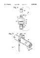
- FIG. 1depicts a bicycle trailer tongue connected to a bicycle using the trailer hitch of the invention.
- FIG. 2is a perspective, partially exploded view of a first embodiment of the hitch of the invention.
- FIG. 3is an exploded, top plan view of a first embodiment of the hitch of the invention.
- FIG. 4is an exploded, top plan view of a second embodiment of the hitch of the invention.
- FIG. 5depicts the use of a safety strap on a bicycle frame having a mono-stay.
- Hitch 10is intended for use in joining a trailer (not shown) having a trailer tongue 12.
- the trailer which incorporates tongue 12may be of the type shown in U.S. Pat. No. 5,020,814 to George et al., granted Jun. 4, 1991, or to the application of Derven et al., Ser. No. 08/932,940, filed Sep. 17, 1997, for folding bicycle trailer.
- Bicycle 13includes a frame, partially shown at 14, which has a pair of spaced apart horizontal chain stays 16, 18 and a pair of slanted, upwardly extending seat stays 20, 22.
- the staysare joined at the rear of the frame to a rear wheel mounting structure, or drop-out, 24, which mounts a rear wheel 26 to the frame.
- Rear wheel 26includes a hub 27.
- a rear axle 28, having an axis of rotation, A,extends through hub 27.
- rear axle 28is of the quick-release type.
- axle 28In a quick-release hub, axle 28 includes a hollow tube extending through the hub and a skewer extending through the hollow portion of the axle to hold the wheel to the frame.
- a solid axleextends through the hub, is bearing mounted therein, and extends beyond the edges of the hub through drop-outs 24.
- Hitch 10includes a hitch mount 30 secured to rear axle 28.
- Hitch mount 30includes a hitch mount body 32, which is rotatable relative to frame 14 and which includes a hitch connector receiver 34 carried thereon.
- receiver 34includes a pair of spaced-apart tabs 36, 38 which receive a hitch connector 40 therebetween. Each tab has a bore, 36a, 38a, respectively, formed therein.
- Hitch connector 40includes a first bore 40a and a second bore 40b formed therein. Hitch connector 40 is received in trailer tongue 12 and secured therein by means of a fastener 42 which, in the preferred embodiment, takes the form of a nut-and-bolt combination, which passes through the trailer tongue and bore 40b.
- a D-ring 44is provided, and secured to tongue 12 by means of fastener 42. Additionally, a safety strap 46 is secured at one end thereof to trailer tongue 12 by means of fastener 42. Strap 46 includes a snap fastener 48 at the other end thereof, which may be connected to D-ring 44. Additionally, a removable pin 50 is fixed to safety strap 46 and is used to secure hitch connector 40 to hitch connector receiver 34. Pin 50 is passed through bores 36a, 38a, and 40a to secure connector 40 to hitch connector receiver 34. Safety strap 46 is trainable about bicycle frame 14 to prevent separation of the trailer from the bicycle in the event that, for some unforeseen reason, any part of hitch 10 should come loose. It should be noted that in the preferred embodiment, pin 50 is equipped with a bail 52 which snaps into place to prevent accidental removal of pin 50 from hitch 10.
- the first embodiment of the hitch mount and hitch-mount retainer mechanismutilizes what is known as a quick-release mechanism.
- Such mechanismincludes an elongate skewer 54 which extends through hub 27. Skewer 54 is slightly longer than a conventionally supplied quick-release skewer. Skewer 54 includes an enlarged head 56 at one end thereof and a threaded portion 58 at the other end thereof.
- a bore 60extends through enlarged head 56 normal to the longitudinal axis of the skewer, which is collinear with axis of rotation A when the hitch mount is installed on bicycle 13.
- a nut 62retains a spring 64 on the other end of skewer 54.
- the enlarged head of skewer 54is received in a frame-contacting member 66 of hitch mount 30.
- Frame-contacting member 66is mounted on bicycle frame 14 in contact with rear wheel mounting structure 24.
- Frame-contacting member 66includes a cavity 68 therein which is constructed and arranged to receive head 56 of skewer 54 in a clearance fit.
- a bore 70extends therethrough and is arranged to be normal to axis of rotation A. Bore 70 and bore 60 receive a tensioning handle 72, which has an eccentric portion 74 which, when properly adjusted with nut 62, applies an axle-fixing tension to skewer 54, thereby holding skewer 54 and, in turn, holding hub 27 and axle 28 in place on frame 14.
- hitch mount 30fit together within hitch mount body 32.
- Skewer 54passes through a sleeve 76 and a guide 78 inside cavity 68.
- a bearing 80is located between hitch mount body 32 and frame-contacting member 66 for providing relative rotation therebetween. Bearing 80 is held in place within hitch mount body 32 by a clip 82, which is received in a groove in hitch mount body 32.
- a second clip 84is installed on the detent 86 of frame-contacting member 66 to hold the entire structure together.
- hitch connector receiver 34is constructed and arranged to allow yaw-only movement of hitch connector 40 relative thereto.
- hitch mount body 32may rotate relative to frame 14
- movement of hitch connector 40 relative to the framemay take place in only two axes: yaw and pitch.
- the arrangementallows only limited roll movement due to the flexion of the hitch connector, enabling limited tipping of the bicycle relative to a two-wheel trailer.
- the embodiment of the bicycle trailer hitch depicted at 90is intended for use on a bicycle that does not have the quick-release rear wheel mounting, and has a solid or threaded axle extending through the hub of the real wheel.
- the componentsare substantially similar to that of the first embodiment, and where appropriate, are identified by like reference numbers.
- the differenceis the use of a barrel nut 92, or threaded fastener, as a retainer mechanism, which is secured to the threaded axle of the rear wheel, thereby holding the trailer hitch in place on the bicycle.
- Barrel nut 92passes through hitch mount body 32 and is received in cavity 68 of frame contacting member 66.
- the trailer hitch of the inventionIn order to install the trailer hitch of the invention on a bicycle, it may first be necessary to install connector 40 in the trailer tongue, if the trailer tongue does not already have an appropriate connector. This is done by removing any original connector and inserting the connector of the invention, securing same thereto with fastener 42. In order to install the bicycle side of the hitch, it is necessary to remove the original quick-release mechanism from the rear wheel of the bicycle.
- the hitch mountis installed by replacing the original quick-release mechanism with skewer 54 (and its associated nut 62 and spring 64), and inserting skewer 54 with the attached hitch mount body and the frame-contacting member, placing the frame-contacting member in contact with the rear-wheel mounting structure with the skewer extending through the rear axle.
- the retaining nut on the non-drive side of the rear wheelis simply removed, the hitch mount is inserted over the axle, and barrel nut 92 is installed and properly tightened.
- safety strap 46when the hitch is used on a bicycle 100 having a mono-stay system 102, safety strap 46 must be trained about the mono-stay so as to be retained by a cantilever brake stud 104, or other structure which protrudes from the mono-stay, so that the strap will not slip off of the mono-stay if the rear wheel comes loose, nor become wrapped about the rear axle.
Landscapes
- Engineering & Computer Science (AREA)
- Transportation (AREA)
- Mechanical Engineering (AREA)
- Fittings On The Vehicle Exterior For Carrying Loads, And Devices For Holding Or Mounting Articles (AREA)
Abstract
Description
Claims (20)
Priority Applications (1)
| Application Number | Priority Date | Filing Date | Title |
|---|---|---|---|
| US09/144,737US6099008A (en) | 1998-09-01 | 1998-09-01 | Hitch for bicycle trailer |
Applications Claiming Priority (1)
| Application Number | Priority Date | Filing Date | Title |
|---|---|---|---|
| US09/144,737US6099008A (en) | 1998-09-01 | 1998-09-01 | Hitch for bicycle trailer |
Publications (1)
| Publication Number | Publication Date |
|---|---|
| US6099008Atrue US6099008A (en) | 2000-08-08 |
Family
ID=22509899
Family Applications (1)
| Application Number | Title | Priority Date | Filing Date |
|---|---|---|---|
| US09/144,737Expired - LifetimeUS6099008A (en) | 1998-09-01 | 1998-09-01 | Hitch for bicycle trailer |
Country Status (1)
| Country | Link |
|---|---|
| US (1) | US6099008A (en) |
Cited By (22)
| Publication number | Priority date | Publication date | Assignee | Title |
|---|---|---|---|---|
| US6305703B1 (en)* | 1999-12-30 | 2001-10-23 | Walter Ray Quick | Bicycle trailer |
| US6540238B2 (en)* | 2001-08-16 | 2003-04-01 | Peng-Yao Yang | Coupling device for connecting a skate board with a baby carriage |
| US6663126B2 (en)* | 2001-09-28 | 2003-12-16 | 634182 Alberta Ltd. | Bicycle trailer hitch |
| EP1184275A3 (en)* | 2000-08-30 | 2004-09-08 | Brüggli Produktion & Dienstleistung | Coupling arrangement for a bicycle hub |
| US20040173988A1 (en)* | 2001-09-28 | 2004-09-09 | Alberta Ltd. | Bicycle trailer hitch |
| US20050173887A1 (en)* | 2004-02-11 | 2005-08-11 | Johnny Chen | Four-link connecting device for connecting a trailer to a bicycle |
| US20060032681A1 (en)* | 2004-08-16 | 2006-02-16 | Everett Richard C | Trailer hitch assembly for a bicycle |
| US20060105834A1 (en)* | 2004-11-12 | 2006-05-18 | CRAWFORD Thomas | Pet transporter |
| US7131657B1 (en)* | 2004-07-27 | 2006-11-07 | Zz Bike, Llc | Bicycle trailer hitch |
| US20070222184A1 (en)* | 2006-03-24 | 2007-09-27 | Christopher Nicholas G | Vehicle hitch assembly for a vehicle and method of utilizing the same |
| US20080023234A1 (en)* | 2006-07-27 | 2008-01-31 | Linghsiao Jerry Wang | Self controlled, electric powered trailer |
| WO2009067818A1 (en)* | 2007-11-30 | 2009-06-04 | Imad Assaf | Light transport vehicle |
| US20110068558A1 (en)* | 2009-09-22 | 2011-03-24 | Burley Design Llc | Bicycle trailer hitch and method |
| US20120000952A1 (en)* | 2010-07-01 | 2012-01-05 | Jason Matthew Dreger | Bike rack |
| US20120200059A1 (en)* | 2011-02-09 | 2012-08-09 | Stephen Rodgers | Trailer hitch for use on a bicycle and a trailer associated therewith |
| US8240695B1 (en)* | 2010-07-14 | 2012-08-14 | Cheh-Kang Liu | Baby trailer towing connector |
| US20130105184A1 (en)* | 2011-11-02 | 2013-05-02 | Kelly Wroolie | Dual Blade Parallel Garden Hoe |
| DE202013101676U1 (en) | 2012-04-18 | 2013-06-17 | Zwei Plus Zwei Gmbh | Self-locking compact clutch |
| US10024029B1 (en)* | 2017-06-28 | 2018-07-17 | Jaime Ruiz | Demolition system |
| US11046385B1 (en) | 2019-05-02 | 2021-06-29 | Burley Design Llc | Bicycle trailer hitch for mounting to a bicycle seat post |
| US11173759B2 (en) | 2019-09-03 | 2021-11-16 | Douglas Larson | Two-wheel vehicle trailer-coupling assembly |
| US12233984B2 (en)* | 2021-10-14 | 2025-02-25 | Thule Sweden Ab | Bicycle trailer hitch |
Citations (12)
| Publication number | Priority date | Publication date | Assignee | Title |
|---|---|---|---|---|
| US26806A (en)* | 1860-01-10 | Improved meat-cutter | ||
| US3387859A (en)* | 1966-03-28 | 1968-06-11 | Leslie L Mcclellan | Trailer for motor bikes |
| USRE26806E (en) | 1969-03-18 | 1970-03-03 | Two-wheeled utility trailers for cycles and hitches therefor | |
| US3567249A (en)* | 1969-03-18 | 1971-03-02 | Russell S Robinson | One-wheeled cycle trailer and hitch therefor |
| US3762748A (en)* | 1972-06-30 | 1973-10-02 | United Aircraft Corp | Linkage connecting means |
| US3934666A (en)* | 1974-01-02 | 1976-01-27 | Ellington Robert W | Bike booster |
| US3993320A (en)* | 1974-06-13 | 1976-11-23 | Robinson Russell S | Resilient hitch for cycle trailer |
| US4721320A (en)* | 1987-04-27 | 1988-01-26 | Burley Design Cooperative, Inc. | Bicycle trailer hitch |
| US5171034A (en)* | 1991-06-13 | 1992-12-15 | Scott James R | Trailer for two-wheeled vehicle |
| US5267744A (en)* | 1992-05-14 | 1993-12-07 | Burley Design Cooperative | Stroller wheel assembly for bicycle trailer |
| US5516131A (en)* | 1994-09-09 | 1996-05-14 | B.O.B. Trailers, Inc. | Quick-release skewer with trailer attachment points |
| US5713698A (en)* | 1996-04-09 | 1998-02-03 | Macmillan Bloedel Limited | Synthetic boomstick coupling system |
- 1998
- 1998-09-01USUS09/144,737patent/US6099008A/ennot_activeExpired - Lifetime
Patent Citations (12)
| Publication number | Priority date | Publication date | Assignee | Title |
|---|---|---|---|---|
| US26806A (en)* | 1860-01-10 | Improved meat-cutter | ||
| US3387859A (en)* | 1966-03-28 | 1968-06-11 | Leslie L Mcclellan | Trailer for motor bikes |
| USRE26806E (en) | 1969-03-18 | 1970-03-03 | Two-wheeled utility trailers for cycles and hitches therefor | |
| US3567249A (en)* | 1969-03-18 | 1971-03-02 | Russell S Robinson | One-wheeled cycle trailer and hitch therefor |
| US3762748A (en)* | 1972-06-30 | 1973-10-02 | United Aircraft Corp | Linkage connecting means |
| US3934666A (en)* | 1974-01-02 | 1976-01-27 | Ellington Robert W | Bike booster |
| US3993320A (en)* | 1974-06-13 | 1976-11-23 | Robinson Russell S | Resilient hitch for cycle trailer |
| US4721320A (en)* | 1987-04-27 | 1988-01-26 | Burley Design Cooperative, Inc. | Bicycle trailer hitch |
| US5171034A (en)* | 1991-06-13 | 1992-12-15 | Scott James R | Trailer for two-wheeled vehicle |
| US5267744A (en)* | 1992-05-14 | 1993-12-07 | Burley Design Cooperative | Stroller wheel assembly for bicycle trailer |
| US5516131A (en)* | 1994-09-09 | 1996-05-14 | B.O.B. Trailers, Inc. | Quick-release skewer with trailer attachment points |
| US5713698A (en)* | 1996-04-09 | 1998-02-03 | Macmillan Bloedel Limited | Synthetic boomstick coupling system |
Cited By (41)
| Publication number | Priority date | Publication date | Assignee | Title |
|---|---|---|---|---|
| US6305703B1 (en)* | 1999-12-30 | 2001-10-23 | Walter Ray Quick | Bicycle trailer |
| EP1184275A3 (en)* | 2000-08-30 | 2004-09-08 | Brüggli Produktion & Dienstleistung | Coupling arrangement for a bicycle hub |
| US6540238B2 (en)* | 2001-08-16 | 2003-04-01 | Peng-Yao Yang | Coupling device for connecting a skate board with a baby carriage |
| US6663126B2 (en)* | 2001-09-28 | 2003-12-16 | 634182 Alberta Ltd. | Bicycle trailer hitch |
| US20040173988A1 (en)* | 2001-09-28 | 2004-09-09 | Alberta Ltd. | Bicycle trailer hitch |
| US6929274B2 (en) | 2001-09-28 | 2005-08-16 | 634182 Alberta Ltd. | Bicycle trailer hitch |
| US20050173887A1 (en)* | 2004-02-11 | 2005-08-11 | Johnny Chen | Four-link connecting device for connecting a trailer to a bicycle |
| US7131657B1 (en)* | 2004-07-27 | 2006-11-07 | Zz Bike, Llc | Bicycle trailer hitch |
| US7207586B2 (en)* | 2004-08-16 | 2007-04-24 | Everett Richard C | Trailer hitch assembly for a bicycle |
| US20060032681A1 (en)* | 2004-08-16 | 2006-02-16 | Everett Richard C | Trailer hitch assembly for a bicycle |
| US20060105834A1 (en)* | 2004-11-12 | 2006-05-18 | CRAWFORD Thomas | Pet transporter |
| US7152554B2 (en) | 2004-11-12 | 2006-12-26 | CRAWFORD Thomas | Pet transporter |
| US20070222184A1 (en)* | 2006-03-24 | 2007-09-27 | Christopher Nicholas G | Vehicle hitch assembly for a vehicle and method of utilizing the same |
| US7591478B2 (en) | 2006-03-24 | 2009-09-22 | Nicholas G. Christopher | Vehicle hitch assembly for a vehicle and method of utilizing the same |
| US20080023234A1 (en)* | 2006-07-27 | 2008-01-31 | Linghsiao Jerry Wang | Self controlled, electric powered trailer |
| WO2009067818A1 (en)* | 2007-11-30 | 2009-06-04 | Imad Assaf | Light transport vehicle |
| US20100244405A1 (en)* | 2007-11-30 | 2010-09-30 | Imad Assaf | Light Transport Vehicle |
| US8091908B2 (en) | 2009-09-22 | 2012-01-10 | Burley Design Llc | Bicycle trailer hitch |
| US20110068560A1 (en)* | 2009-09-22 | 2011-03-24 | Burley Design Llc | Bicycle trailer and method |
| US20110068558A1 (en)* | 2009-09-22 | 2011-03-24 | Burley Design Llc | Bicycle trailer hitch and method |
| US8419035B2 (en) | 2009-09-22 | 2013-04-16 | Burley Design Llc | Bicycle trailer and method |
| US20120000952A1 (en)* | 2010-07-01 | 2012-01-05 | Jason Matthew Dreger | Bike rack |
| US9254790B2 (en)* | 2010-07-01 | 2016-02-09 | Cequent Performance Products, Inc. | Bike rack |
| US8240695B1 (en)* | 2010-07-14 | 2012-08-14 | Cheh-Kang Liu | Baby trailer towing connector |
| US20120200059A1 (en)* | 2011-02-09 | 2012-08-09 | Stephen Rodgers | Trailer hitch for use on a bicycle and a trailer associated therewith |
| US8282117B2 (en)* | 2011-02-09 | 2012-10-09 | Stephan M Rodgers | Trailer hitch for use on a bicycle and a trailer associated therewith |
| US20130105184A1 (en)* | 2011-11-02 | 2013-05-02 | Kelly Wroolie | Dual Blade Parallel Garden Hoe |
| WO2013156578A1 (en) | 2012-04-18 | 2013-10-24 | Zwei Plus Zwei Gmbh | Self-locking compact coupling |
| EP3309051A1 (en) | 2012-04-18 | 2018-04-18 | Croozer GmbH | Self-locking compact coupling |
| US20150115573A1 (en)* | 2012-04-18 | 2015-04-30 | Zwei Plus Zwei Gmbh | Self-locking compact coupling |
| DE202013101676U1 (en) | 2012-04-18 | 2013-06-17 | Zwei Plus Zwei Gmbh | Self-locking compact clutch |
| DE202013012643U1 (en) | 2012-04-18 | 2018-02-05 | Croozer Gmbh | Self-locking compact clutch |
| DE202013012641U1 (en) | 2012-04-18 | 2018-02-05 | Croozer Gmbh | Self-locking compact clutch |
| DE202013012639U1 (en) | 2012-04-18 | 2018-02-05 | Croozer Gmbh | Self-locking compact clutch |
| DE102012103404A1 (en) | 2012-04-18 | 2013-10-24 | Zwei Plus Zwei Gmbh | Self-locking compact clutch |
| DE102012103404B4 (en) | 2012-04-18 | 2022-06-30 | Croozer Gmbh | Self-locking compact coupling and system consisting of a vehicle and a vehicle trailer having a drawbar with a coupling for connecting the drawbar to the vehicle |
| EP3680160A1 (en) | 2012-04-18 | 2020-07-15 | Croozer GmbH | Self-locking compact coupling |
| US10024029B1 (en)* | 2017-06-28 | 2018-07-17 | Jaime Ruiz | Demolition system |
| US11046385B1 (en) | 2019-05-02 | 2021-06-29 | Burley Design Llc | Bicycle trailer hitch for mounting to a bicycle seat post |
| US11173759B2 (en) | 2019-09-03 | 2021-11-16 | Douglas Larson | Two-wheel vehicle trailer-coupling assembly |
| US12233984B2 (en)* | 2021-10-14 | 2025-02-25 | Thule Sweden Ab | Bicycle trailer hitch |
Similar Documents
| Publication | Publication Date | Title |
|---|---|---|
| US6099008A (en) | Hitch for bicycle trailer | |
| US5470088A (en) | Bicycle trailer hitch assembly and bicycle trailer incorporating same | |
| US4721320A (en) | Bicycle trailer hitch | |
| US5695208A (en) | Baby stroller conversion assembly | |
| US4548423A (en) | Universal trailer hitch | |
| US5348327A (en) | Collapsible manually towed or bicycle trailered sailboard dolly | |
| US5842710A (en) | Coupling device for bicycles | |
| US4883283A (en) | Improved hitch and suspension for one-wheel cycle trailers | |
| US3567249A (en) | One-wheeled cycle trailer and hitch therefor | |
| EP3402715B1 (en) | Cargo bicycle conversion system | |
| US7273221B2 (en) | Attachment system for bicycle accessories | |
| US5669618A (en) | Bicycle trailer | |
| US6042138A (en) | Motorcycle trailer apparatus | |
| US5242178A (en) | Hitch for attaching a trailer to a bicycle | |
| US6612389B1 (en) | Combination trailer and two-wheel conversion utility for a motorcycle | |
| US4487344A (en) | Pannier carrier for bicycles | |
| US6305702B1 (en) | Quick-release attachment device for motorcycles with concealed receiver assembly | |
| US6663126B2 (en) | Bicycle trailer hitch | |
| US6929274B2 (en) | Bicycle trailer hitch | |
| US4203612A (en) | Velocipede having separable frame parts | |
| US20010038190A1 (en) | Bicycle accessory | |
| US4819956A (en) | Convertible sidecar/trailer | |
| US6688622B2 (en) | Bicycle transporter | |
| US6749212B2 (en) | Bicycle trailer hitch or accessory mount | |
| EP0933288A3 (en) | Parking device for two-wheeler |
Legal Events
| Date | Code | Title | Description |
|---|---|---|---|
| AS | Assignment | Owner name:BURLEY DESIGN COOPERATIVE, OREGON Free format text:ASSIGNMENT OF ASSIGNORS INTEREST;ASSIGNOR:CAFFEY, STEPHEN PATRICK;REEL/FRAME:009437/0128 Effective date:19980831 | |
| FPAY | Fee payment | Year of fee payment:4 | |
| AS | Assignment | Owner name:BFI BUSINESS FINANCE, CALIFORNIA Free format text:SECURITY AGREEMENT;ASSIGNOR:BURLEY DESIGN COOPERATIVE;REEL/FRAME:015740/0791 Effective date:20050211 | |
| AS | Assignment | Owner name:BURLEY DESIGN L.L.C., OREGON Free format text:ASSIGNMENT OF ASSIGNORS INTEREST;ASSIGNOR:BURLEY DESIGN, INC., FORMERLY KNOWN AS BURLEY DESIGN COOPERATIVE;REEL/FRAME:018350/0772 Effective date:20060908 | |
| REMI | Maintenance fee reminder mailed | ||
| REIN | Reinstatement after maintenance fee payment confirmed | ||
| FP | Lapsed due to failure to pay maintenance fee | Effective date:20080808 | |
| FEPP | Fee payment procedure | Free format text:PETITION RELATED TO MAINTENANCE FEES FILED (ORIGINAL EVENT CODE: PMFP); ENTITY STATUS OF PATENT OWNER: SMALL ENTITY | |
| FEPP | Fee payment procedure | Free format text:PETITION RELATED TO MAINTENANCE FEES GRANTED (ORIGINAL EVENT CODE: PMFG); ENTITY STATUS OF PATENT OWNER: SMALL ENTITY | |
| AS | Assignment | Owner name:BURLEY DESIGN, INC., OREGON Free format text:ARTICLES OF CONVERSION;ASSIGNOR:BURLEY DESIGN COOPERATIVE;REEL/FRAME:023814/0686 Effective date:20060623 | |
| FPAY | Fee payment | Year of fee payment:8 | |
| SULP | Surcharge for late payment | ||
| AS | Assignment | Owner name:BURLEY DESIGN COOPERATIVE,OREGON Free format text:RELEASE BY SECURED PARTY;ASSIGNOR:BFI BUSINESS FINANCE;REEL/FRAME:023915/0960 Effective date:20061011 | |
| PRDP | Patent reinstated due to the acceptance of a late maintenance fee | Effective date:20100409 | |
| STCF | Information on status: patent grant | Free format text:PATENTED CASE | |
| FPAY | Fee payment | Year of fee payment:12 |