US6098839A - Article dispensing assembly - Google Patents
Article dispensing assemblyDownload PDFInfo
- Publication number
- US6098839A US6098839AUS09/074,255US7425598AUS6098839AUS 6098839 AUS6098839 AUS 6098839AUS 7425598 AUS7425598 AUS 7425598AUS 6098839 AUS6098839 AUS 6098839A
- Authority
- US
- United States
- Prior art keywords
- article
- magazine
- support
- dispensing apparatus
- cassette
- Prior art date
- Legal status (The legal status is an assumption and is not a legal conclusion. Google has not performed a legal analysis and makes no representation as to the accuracy of the status listed.)
- Expired - Lifetime
Links
Images


Classifications
- B—PERFORMING OPERATIONS; TRANSPORTING
- B65—CONVEYING; PACKING; STORING; HANDLING THIN OR FILAMENTARY MATERIAL
- B65H—HANDLING THIN OR FILAMENTARY MATERIAL, e.g. SHEETS, WEBS, CABLES
- B65H1/00—Supports or magazines for piles from which articles are to be separated
- B65H1/04—Supports or magazines for piles from which articles are to be separated adapted to support articles substantially horizontally, e.g. for separation from top of pile
- B65H1/06—Supports or magazines for piles from which articles are to be separated adapted to support articles substantially horizontally, e.g. for separation from top of pile for separation from bottom of pile
Definitions
- This inventionrelates to dispensing assemblies for dispensing individual articles and, more particularly, to cassette dispensing assemblies for dispensing sample support cassette articles for subsequent histological analysis.
- Biomedical laboratoriescommonly utilize rectangular plastic trays of a specified size and shape, called sample cassettes, to hold biological samples for histological analysis or other testing.
- the cassettesare single use disposable articles which are stored in bulk and require individual labeling and dispensing prior to use.
- the cassettesare generally rectangular and have an angled face for labeling which can be presented to a marking device.
- One device for marking and dispensing sample cassettesis known as the Shur-Mark Cassette labeler.
- Another device for labeling and dispensingis illustrated in UK Patent Application GB 2 235 163 A, filed Jun. 28, 1990 in the name of Pauline D. Lamb. Lamb discloses a device for marking supports for laboratory samples, for example (a) laboratory tissue processing cassettes made of plastic material and (b) glass laboratory or microscope slides.
- the marking device disclosed in the Lamb patent applicationcomprises a marking stylus operatively coupled to a plotter mechanism for applying a selected marking to the sample support article at a marking locus, with means for holding a sample support article in selected position at the marking locus for the marking operation.
- This marking deviceincludes a mechanism for ejecting the sample support article from the holding means subsequent to marking of the sample support article.
- the sample support articlesare supplied to the marking locus of the device disclosed in the Lamb patent application from a magazine mounted above a slide tray extending from an upper feed end downwardly to a lower discharge end communicating with the aforementioned holding means which secure the sample support article during its marking.
- the magazineis manually loaded, one-by-one, with the sample support articles to form a stack of the articles in the interior volume of the magazine.
- a rotary reciprocating block of a selected shapewhich permits the release of a single sample support article at a time, from the magazine, as the block is rotated to its release position and then returned to its "blocking" position, to retain the next succeeding sample support article in the magazine, pending release on the next rotation cycle of the block member.
- the magazine in the Lamb deviceis difficult to manually load in a quick manner, such as may be desired for continuous operation of the device in the service of labeling a large number of support articles.
- the sample support articles dropped into the upper end of the magazine housingmay, in dropping onto the existing stack of articles, become misregistered in relation to the already stacked articles, with the result that the misregistered article may have to be manually re-registered, or the labeling device may have to be shaken or tapped to cause the misregistered article to properly reseat itself in position on the existing stack of the support articles.
- Such treatment of the labeling devicemay in turn cause damage to the device itself and/or cause additional support articles in the previously existing stack to themselves become misregistered.
- manual loading of the magazine in the Lamb deviceis time-consuming, in terms of the associated technician's time, which otherwise could be usefully employed in other laboratory operations.
- the reciprocating block mechanism for ejecting the cassettescan function improperly.
- the blockacts as both the release and retention member which can cause misregistration of stacked cassettes.
- the Lamb deviceis difficult to load in a quick fashion while insuring accurate alignment and stacking of the support articles in the vertical feed hopper, and loading in any event is time-consuming and labor intensive. Further, the reciprocating block release mechanism can cause misalignment and consequent improper sample cassette dispensing.
- a sample support cassette article dispensing assemblyfor storing and sequentially translating sample support articles, the assembly constructed, arranged, and adapted to be removeably positioned in operative relation to a support article labeling device.
- the assemblyincludes a sequencing mechanism and a housing containing the sequencing mechanism.
- the housingcan be adapted for receiving a preloaded magazine for holding sample support cassette articles.
- the sequencing mechanismcaptures a stacked array of support articles and translates a bottom-positioned support article from the stacked array to the labeling device.
- the housingcan optionally include at least one adjustable stop element comprising a ledge formed by an edge of an opening in the housing. The stop element cooperates with the sequencing mechanism to prevent misregistration of the bottom-positioned support article, independent of the cassette face angle.
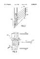
- FIG. 1shows an article dispensing assembly for storing and sequentially translating articles.
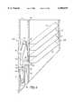
- FIG. 2is a side view of an embodiment of a housing of the present invention.
- FIG. 3is a perspective view of the components of the sequencing mechanism of the present invention.
- FIG. 4is a cross-sectional side view of an embodiment of a housing of the present invention detailing the sequencing mechanism.
- FIG. 5is a cross-sectional view of an embodiment of a sequencing mechanism at zero degrees of rotation.
- FIG. 6is a cross-sectional view of an embodiment of a sequencing mechanism at five degrees of rotation.
- FIG. 7is a cross-sectional view of an embodiment of a sequencing mechanism at ten degrees of rotation.
- FIG. 8is a cross-sectional view of an embodiment of a sequencing mechanism at fifteen degrees of rotation.
- FIG. 9is a cross-sectional view of an embodiment of a sequencing mechanism at twenty degrees of rotation.
- FIG. 10is a cross-sectional view of an embodiment of a sequencing mechanism at twenty-five degrees of rotation.
- FIG. 11is a cross-sectional view of an embodiment of a sequencing mechanism at thirty degrees of rotation.
- FIG. 12is a cross-sectional view of an embodiment of a sequencing mechanism at thirty-five degrees of rotation.
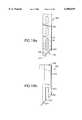
- FIG. 13is a side view of an embodiment of a catching member.
- FIG. 14is a side view of an embodiment of an actuator.
- FIG. 15is a front view of an embodiment of a holding member.
- FIG. 16is a side view of an embodiment of the holding member of FIG. 15.
- FIG. 17is a perspective view of an embodiment of a magazine of the present invention.
- FIG. 18ais a side view of one embodiment of a magazine holding an array of cassette articles.
- FIG. 18bis a side view of one embodiment of the base support member with a view slot for viewing the inserted magazine and stacked array of cassette articles.
- FIG. 19ais a side view of a second embodiment of a magazine holding an array of cassette articles.
- FIG. 19bis a side view of another embodiment of the base support member having an open front face.
- FIG. 20is a sectional view of an embodiment of the housing along line A--A of FIG. 1.
- FIG. 1illustrates an article dispensing apparatus 100 for storing and sequentially translating support articles 41. Assembly 100 may also dispense articles for subsequent labeling or may also receive labeled articles.
- the apparatusis constructed, arranged, and adapted to be removeably positioned in operative relation to an article labeling device 500.
- the embodiment of apparatus 100 depicted in FIG. 1includes base support 230 and magazine 400.
- Base support 230includes housing 200 containing a sequencing mechanism 300.
- a cut away view of housing 200is depicted to illustrate the location of sequencing mechanism 300 within the housing.
- Sleeve 250 of housing 200is constructed and arranged to directly hold articles in a first embodiment or to removeably mount a magazine 400 containing a stacked array of articles (cassettes 41) in a second embodiment.
- Magazine 400has a dispensing end 440 insertable into housing sleeve 250 and a support leg 402 for securing magazine 400 into operative position inside housing 200.
- View windows 420are provided on the side walls of magazine 400 to monitor dispensing of cassettes 41.
- the articlesare cassettes of a conventional and known type as used for containment, storage, and presentation of tissue samples for histological analysis.
- the cassettes 41are illustrative of exemplary articles which can be dispensed by the teachings of the present invention.
- FIG. 2is a side view of an embodiment of housing 200 containing sequencing mechanism 300.
- the cassettes 41are held directly within sleeve 250 or, optionally inside magazine 400 as depicted in FIG. 1.
- An array of cassettes 41are held within housing 200 by sequencing mechanism 300, which secures bottom-positioned support article 42.
- FIG. 3illustrates the components of the sequencing mechanism 300 in operative relationship.
- the sequencing mechanism 300includes an actuator 37 mounted on a drive shaft 36.
- Set screw 38is used to secure the actuator 37 to the shaft 36 so that actuator 37 rotates with drive shaft 36.
- Drive shaft 36includes a keyed end 63 to mate with driver 510 of labeling machine 500 as depicted in FIGS. 1 and 20.
- Catching member 31is mounted on shaft 33 and rotates about shaft 33 when actuator 37 pushes against catching member 31.
- Holding member 34is mounted on shaft 39. The rotational operation among actuator 37, catching member 31 and holding member 34 is described more fully below.
- FIG. 4is a side view of an embodiment showing housing 200 containing sequencing mechanism 300 which captures a stacked array 41 of support articles and translates bottom-positioned support article 42 from stacked array 41 to the labeling device 500 depicted in FIG. 1.
- Sequencing mechanism 300includes a catching member 31, a holding member 34, and an actuator 37.
- Catching member 31is mounted to housing 200 and is designed to catch stacked array 41 during sequential translation.
- Catching member 31is rotatably mounted between first sidewall 27 and opposite second sidewall 28 (not shown) of the housing on shaft 33.
- Catching member 31includes a projection 32 to retain stacked array 41 above the bottom-positioned support article 42 and to prevent multiple support articles from being released during sequential translation.
- Wall 24 of housing 200prevents projection 32 from disturbing a desired orientation of bottom-positioned support article 42 by limiting the rotation of catching member 31 about its mounting shaft.
- Shaft 33is rotatably mounted between the first sidewall 27 and the opposite second sidewall 28 (not shown), with the catching member 31 fixed to the first shaft. Spring 35 restores catching member 31 to neutral position, after the sequential translation is complete.
- FIG. 4a side view is provided of housing 200 containing sequencing mechanism 300 and holding member 34 mounted to housing 200 and designed to hold and then release the lower-most article 42 in stacked array 41.
- the holding member 34is rotatably mounted on shaft 39 between first sidewall 27 and opposite second sidewall 28 (not shown).
- the holding member 34is biased into contact with shaft 36 by spring 51.
- Holding member 34includes at least one projection 52 designed to restrain the bottom-positioned support article 42 in a fixed position before labeling by the support article labeling device 500 (depicted in FIG. 1).
- Projection 52includes a curved upper surface to allow for release of article 42 and to control the rate of release of the bottom-positioned support article 42.
- Shaft 39is rotatably mounted between first sidewall 27 and opposite second sidewall 28 (not shown).
- the holding member 34rotates about the axis of shaft 39.
- Spring 51restores the restraining member to a neutral position after the sequential translation is complete.
- Actuator 37is mounted to housing 200 and operatively coupled to catching member 31 and holding member 34 to selectively and sequentially translate support articles from stacked array 41.
- Actuating member 37is rotatably mounted on actuator shaft 36 between first sidewall 27 and opposite second sidewall 28 (not shown).
- the actuator member 37includes a first arm 53 engaging and activating the catching member 31 and a second arm 54 engaging and activating the holding member 34.
- Actuator drive shaft 36is rotatably mounted between first sidewall 27 opposite second sidewall 28 (not shown) of housing 200.
- the actuating member 37is fixed to the actuator drive shaft 36 by set screw 38.
- the actuator shaftfurther includes a keyed end illustrated in FIG. 3 engaging a drive 510 (illustrated in FIGS. 1 and 20) of the support article labeling device 500 to drive the actuator 37 and cause sequential translation.
- Set screw 38is threadably received in actuator 37 for fixing the actuator member to the actuator 37 shaft 36 to prevent rotational slippage.
- FIGS. 5 through 12illustrate the action of sequencing mechanism 300 through the actuation cycle at various degrees of rotation.
- FIG. 5illustrates the actuator member 37 at zero degrees of rotation, and the sequencing mechanism 300 is in an inactive, neutral position.
- Holding member 34is biased against shaft 36 by spring 51 (shown in FIG. 4) in neutral position and restrains the bottom-positioned article 42 on the upper surface of projection 52.
- Catching member 31rests in a neutral position biased against actuator 37 by spring 35 (shown in FIG. 4).
- actuator member 37is rotated five degrees (driven by drive shaft 36, which is being rotated by drive 510 of labeling device 500 as shown in FIGS. 1 and 20). As actuator 37 rotates, first arm 53 begins engaging catching member 31.
- FIG. 7shows actuator 37 rotated ten degrees.
- the actuatorproceeds to rotate holding member 31 and to push projection 32 into stacked array 41 to retain the stacked array 41 above the bottom-positioned support article 42.
- the holding member 34continues to restrain bottom-positioned support article 42.
- FIG. 8shows actuator member 37 rotated fifteen degrees.
- the actuator 37continues rotating catching member 31 into stacked array 41 to ensure projection 32 captures stacked array 41 above the bottom-positioned support article 42.
- Arm 54 of actuator member 37begins to engage holding member 34.
- FIG. 9shows actuator 37 rotated twenty degrees. Actuator member 37 continues rotating catching member projection 32 into stacked array 41, and rotates holding member 34 to withdraw projection 52 to retract and begins to release bottom-positioned support article 42.
- FIG. 10shows actuator member 37 rotated twenty-five degrees. The actuator 37 continues pushing catching member projection 32 into stacked array 41, and holding member 34 is nearly releasing the bottom-positioned support article 42.
- FIG. 11shows actuator 37 rotated thirty degrees.
- Catching member 31almost contacts wall 24, is extended and firmly controls the stacked array 41.
- Holding member 34completely releases the bottom-positioned support article 42.
- FIG. 12shows actuator 37 fully rotated at thirty-five degrees.
- Catching member 31comes in contact with wall 24, and holding member 34 contacts wall 26.
- Both catching member 31 and holding member 34have reached the limit of their respective rotations, and the sequence now begins to reverse, as shaft 36 is rotated in the opposite direction, back to neutral position, FIG. 5.
- the remaining articlesshift down when released by catching member 31 and are held by holding member 34 until the next release, as the sequencing mechanism 300 cycles back from FIG. 12 to FIG. 5.
- FIG. 13is a side view of an embodiment of catching member 31, including a claw-like end 32 to capture stacked array 41 and to prevent multiple support articles from being released during sequential translation.
- the catching memberincludes a hole for the insertion of shaft 33.
- Extension membermay be constructed of aluminum, stainless steel, or plastic.
- FIG. 14is a side view of an embodiment of actuator 37 with arms 53 and 54.
- the actuatorincludes a hole for the insertion of the actuator shaft 36.
- Actuator 37may be constructed of aluminum, stainless steel, or plastic.
- FIG. 15is a front view of an embodiment of holding member 34.
- the holding member 34may be constructed including an opening 356 to allow access of a stylus of the labeling device.
- FIG. 16is a side view of an embodiment of holding member 34.
- the holding memberincludes at least one projection 52 to restrain bottom-positioned support article 42 which has a curved surface 348 to control the rate of release of the bottom-positioned support article 42 . Curved surface 348 can be altered to modify the rate of release of a support article.
- the holding member 34includes a hole for the insertion of shaft 39.
- Holding member 37may be constructed of aluminum, stainless steel, or plastic.
- FIG. 17shows an embodiment of magazine 400.
- the magazinehas an interior volume designed to maintain stacked array 41 in a desired orientation to the labeling device.
- Magazine 400is shown, in this embodiment, devoid of any motive means or members as components thereof. Reference to the magazine as being “devoid of any motive means or members," as used herein, means the magazine has no moving parts which effect sequential dispensing of a bottom-positioned support article 42 from the stacked array.
- Magazine 400is of elongate form defining a longitudinal axis 450 and the magazine has a rectangular cross-section transverse to the longitudinal axis. Magazine 400 is, in this embodiment, constructed of a paper product.
- the interior surfaceis provided with a low tack coating to minimize frictional forces between the dispensed articles 41 and the interior surface of magazine 400.
- View windows 420are provided to monitor the dispensing level of articles 41.
- the paper productis scored and folded to form a first sidewall 472, a second sidewall 474 (not shown), a third sidewall 476 (not shown) opposite first sidewall 472, and a fourth sidewall 478 opposite the second sidewall with the fourth sidewall attached to the first sidewall.
- Support let 402is an extension of side wall 478. Magazine 400 is supported within sleeve 250 by means of stop 202 of housing 200 as shown in FIG. 20. Since the magazine is constructed of a paper product, the magazine may be disposed of when devoid of articles 41.
- the paper product used for magazine 400can be obtained form various sources but must have a low tack, smooth side.
- Two suppliers of such paperinclude Gulf States Paper Corporation and Jefferson Smurfit Corporation.
- the smooth coated surfaceis achieved by using predominantly a hardwood pulp formed into a single ply paperboard countinuous web by a fourdinier paper machine.
- the fourdinier sheetis presssed to remove moisture. Smoothness is provide by the selection of press rolls and felting.
- a wet calender stackis used on the paperboard to impart a hard smooth finish. After removing moisture
- Magazine 400may also include magazine top 412 and bottom pull-away lid 406. After stacking articles 41 into a stacked array within the interior volume of magazine 400, the magazine top is closed in a secured position by conventional closure flap inserts.
- An optional article support orientation insert 414may be placed between top article 43 in the stacked array of articles 41 and the magazine top 412 to reduce article shifting during transportation of the magazine and assist in maintaining the stacked array 41 in a desired orientation to permit frontal face 417 of each article 41 to be correctly aligned with the support article labeling device 500.
- Pull-away lid 406is a detachable bottom of magazine 400 designed to be removed after the magazine has been inserted into sleeve 250 of support base 230 shown in FIGS. 18 and 19.
- Pull-away lid 406is removeably secured to the bottom portion of magazine 400 by a serrated attachment of lid 406 to side wall 474 (not shown) opposite side wall 478 and an adhesive attachment of pull tab 404 to side wall 478.
- pull tab 404is detached from side wall 478 and pulled outwardly separating pull-away lid 406 from the bottom portion of magazine 400.
- Pull-away lid 406may be removeably attached from magazine 400 by means other than a serrated edge or an adhesive attachment. For example, guides or slots means may also be provided to temporarily hold pull-away lid 406 in position until magazine 400 is placed in a dispensing position.
- FIGS. 18a and 18bare side views of magazine 400 and base support 230, respectively. As illustrated by FIGS. 18a and 18b, magazine 400 inserts into sleeve 250 of support base 230.
- Magazine 400is provided with view windows 420 to monitor the dispensing level of articles 41.
- Pull-away tab 406is removeably attached to the dispensing end of magazine 400.
- magazine 400When inserting magazine 400 through sleeve 250, magazine 400 is secured into position within base support 230 by stop 202 which holds support leg 402 of magazine 400.
- Front wall 208is provided with view slot 206 for monitoring articles 41 through view windows 420 of magazine 400.
- Tab opening 204is provided below view slot 206 to allow for access to pull tab 404 after magazine 400 has been fully inserted inside base support 230 through sleeve 250.
- Pull-away lid 406is removeably attached to magazine 400 by means of a serrated tear end (not shown) attached to magazine 400 opposite side wall 478.
- Pull tab 404is removeably adhered to side wall 478 and is preferably biased slightly outward so that it may be easily grasped after insertion of magazine 400 into sleeve 250.
- Base support 230is provided with a back side support slot 203, which secures the assembly to the side wall of article labeling device 500 (depicted in FIGS. 1 and 20).
- FIGS. 19a and 19billustrate an alternative embodiment of the present invention similar to that depicted in FIGS. 18a and 18b.
- magazine 400is provided with a stacked array of articles 41 that may viewed through view windows 420.
- the dispensing end 407 of magazine 400is an alternative embodiment of the pull-away lid 406 shown in FIG. 18a.
- the exact configuration of the removable lidis not crucial so long as it serves the following functions: (1) the removable lid remains secure during movement and transportation of the magazine, and (2) the removable lid is easily detached from the magazine after insertion of the magazine inside the base support without interfering with the dispensing function of the assembly.
- FIG. 19bis an alternative embodiment of a support base 230 having an open front wall. Magazine guide 210 of rear wall 212 and front guide 214 secure magazine 400 from lateral movement after insertion of magazine 400 through sleeve 250 of support base 230. stop 202 of support base 230 holds support leg 402 of magazine 400 to prevent any downward slipping of the magazine after insertion of the magazine into the support base.
- pull tab 410may be grasped and pulled in a downward and outward motion if the attachment means of removable lid 408 is by a serrated edge or adhesive attachment. If removable lid 408 is secured to dispensing end 407 by a slideable means, pull tab 410 may be grasped and slid out in a direction generally along the plane of the dispensing bottom.
- Base support 230is provided with a back side support slot 203, which secures the assembly to the side wall of article labeling device 500 (depicted in FIGS. 1 and 20).
- FIG. 20is a sectional view of housing 200 along line A--A of FIG. 1.
- FIG. 20shows an embodiment of assembly 100 in operative relation with support article labeling device 500. Magazine 400 is shown inserted into housing sleeve 250.
- Base support 230is secured to article labeling device by wall prongs 505 that hook on to back side support slot 203.
- Third sidewall 274also includes a lip or stop 202 holding support leg 402 to retain magazine 400.
- the stacked array of support articles 41is vertically arranged with the individual support articles 41 abuttingly stacked one on another and disposed at an angle with respect to third sidewall 274. Each support article in the stacked array has a desired orientation.
- the desired orientationis determined by an angle of a support article frontal face 417 with respect to a bottom main surface 418 of the support article.
- a low friction coatingis provided on along inside wall 416 to allow articles 41 to slide easily down the interior of magazine 400 as individual articles 41 are dispensed.
- Each support articlemust be held in the desired orientation to ensure each frontal face is properly labeled by the support article labeling device 500.
Landscapes
- Engineering & Computer Science (AREA)
- Mechanical Engineering (AREA)
- Labeling Devices (AREA)
Abstract
Description
Claims (53)
Priority Applications (1)
| Application Number | Priority Date | Filing Date | Title |
|---|---|---|---|
| US09/074,255US6098839A (en) | 1998-05-07 | 1998-05-07 | Article dispensing assembly |
Applications Claiming Priority (1)
| Application Number | Priority Date | Filing Date | Title |
|---|---|---|---|
| US09/074,255US6098839A (en) | 1998-05-07 | 1998-05-07 | Article dispensing assembly |
Publications (1)
| Publication Number | Publication Date |
|---|---|
| US6098839Atrue US6098839A (en) | 2000-08-08 |
Family
ID=22118601
Family Applications (1)
| Application Number | Title | Priority Date | Filing Date |
|---|---|---|---|
| US09/074,255Expired - LifetimeUS6098839A (en) | 1998-05-07 | 1998-05-07 | Article dispensing assembly |
Country Status (1)
| Country | Link |
|---|---|
| US (1) | US6098839A (en) |
Cited By (18)
| Publication number | Priority date | Publication date | Assignee | Title |
|---|---|---|---|---|
| US6263557B1 (en)* | 1997-02-14 | 2001-07-24 | Engel Industries, Inc. | Apparatus and method for inserting angle plates in channel shaped flanges of a duct |
| US6334546B1 (en)* | 2000-07-21 | 2002-01-01 | Austin Wang | Ball cartridge means for storing, delivering and collecting practice ball |
| US6340094B1 (en)* | 1997-10-17 | 2002-01-22 | Sammy Corporation | Premium supply apparatus and lock mechanism of hook for premium supply apparatus |
| EP1238706A3 (en)* | 2001-03-09 | 2003-11-26 | Leica Microsystems Nussloch GmbH | Cassette-stack with cassettes for histological examinations |
| US6832698B1 (en) | 2003-03-19 | 2004-12-21 | Jeffrey Dybul | Container lid dispenser |
| US20050194396A1 (en)* | 2004-03-02 | 2005-09-08 | Expense Management, Inc. | Automated condiment dispensing system |
| WO2007135396A1 (en)* | 2006-05-18 | 2007-11-29 | Thomas Fergus Hughes | Device and method for holding a cassette for laboratory samples |
| US20080187429A1 (en)* | 2004-12-23 | 2008-08-07 | Snaptron, Inc. | Efficient Delivery and Placement Systems For Switch Contacts |
| US7507379B2 (en) | 2004-01-08 | 2009-03-24 | Triangle Biomedical Sciences, Inc. | Unitary assembly of biological specimen support articles, and apparatus for dispensing individual biological specimen support articles therefrom |
| US20090145920A1 (en)* | 2007-09-21 | 2009-06-11 | Ian Kerrod | Tissue cassette dispensing apparatus |
| US7900797B1 (en)* | 2004-01-12 | 2011-03-08 | Daryl Dean Witcraft | Lid separator and dispensing device |
| GB2487507A (en)* | 2007-09-21 | 2012-07-25 | Thermo Shandon Ltd | Tissue cassette dispensing apparatus |
| EP2616820A4 (en)* | 2010-09-13 | 2014-04-09 | Primera Technology Inc | Cartridge for histological specimen slides |
| GB2529667A (en)* | 2014-08-28 | 2016-03-02 | Thomas Fergus Hughes | A device and method for delivering a laboratory sample carrier from a stack of sample carriers |
| US20170113890A1 (en)* | 2014-03-27 | 2017-04-27 | Murrplastik Systemtechnik Gmbh | Device for inscription of identification units |
| US20180105362A1 (en)* | 2015-05-11 | 2018-04-19 | Jiangsu Xunjie Cabinet Technology Co.,Ltd. | Vertical object storage and dispensing device and drug dispensing machine |
| US10370208B2 (en)* | 2016-04-27 | 2019-08-06 | Indag Pouch Partners Gmbh | Batch feeder for piece goods made of flat material |
| CN114227042A (en)* | 2021-12-22 | 2022-03-25 | 浙江农林大学 | Welding machine and method for welding battery soft copper bars |
Citations (30)
| Publication number | Priority date | Publication date | Assignee | Title |
|---|---|---|---|---|
| US30595A (en)* | 1860-11-06 | Improvement in the cutting apparatus of harvesters | ||
| US2829767A (en)* | 1955-09-21 | 1958-04-08 | Charles M Scripture | File case and holder for photographic transparencies |
| US3179314A (en)* | 1964-01-03 | 1965-04-20 | Albemarle Paper Mfg Company | Sliding door construction for corrugated containers and the like |
| US3235068A (en)* | 1964-12-15 | 1966-02-15 | Clay Adams Inc | Combination container and filing means for glass slides |
| US3416250A (en)* | 1966-03-23 | 1968-12-17 | Airequipt Inc | Metal slide magazine |
| US3503496A (en)* | 1967-05-31 | 1970-03-31 | Meopta Narodni Podnik | Slide magazine for a photographic projector |
| US3799409A (en)* | 1972-10-11 | 1974-03-26 | Owens Corning Fiberglass Corp | Shippable dispensing container |
| US4077845A (en)* | 1977-04-20 | 1978-03-07 | Miles Laboratories, Inc. | Disposable inoculation device and process of using same |
| US4114166A (en)* | 1976-12-10 | 1978-09-12 | Polaroid Corporation | Self-developing camera and viewer |
| US4142863A (en)* | 1978-06-05 | 1979-03-06 | Eastman Kodak Company | Article container for dispensing reagent slides |
| US4151931A (en)* | 1978-06-05 | 1979-05-01 | Eastman Kodak Company | Article dispenser apparatus for use in an automated chemical analyzer |
| US4151915A (en)* | 1976-07-09 | 1979-05-01 | Smithkline Corporation | Slide smearing device |
| US4187077A (en)* | 1978-06-05 | 1980-02-05 | Eastman Kodak Company | Container with article positioning element for dispensing reagent coated slides to an automated analyzer |
| US4190420A (en)* | 1978-06-05 | 1980-02-26 | Eastman Kodak Company | Container for dispensing articles to an automated analyzer |
| USRE30595E (en) | 1978-06-05 | 1981-04-28 | Eastman Kodak Company | Article container for dispensing reagent slides |
| US4301116A (en)* | 1979-05-11 | 1981-11-17 | Olympus Optical Co., Ltd. | Sample tray feeding apparatus for use with an automated analyzer |
| US4305526A (en)* | 1980-02-11 | 1981-12-15 | Pfleger Frederick W | Device for dispensing articles from a boxed stack |
| US4334361A (en)* | 1979-04-23 | 1982-06-15 | Gorski Carol A | Pasta gauge |
| US4387512A (en)* | 1979-04-23 | 1983-06-14 | Gorski Carol A | Pasta gauge and container |
| US4512952A (en)* | 1982-07-01 | 1985-04-23 | Eastman Kodak Company | Apparatus for storing and dispensing analysis slides |
| US4776689A (en)* | 1986-06-11 | 1988-10-11 | Slide Management Systems, Inc. | Slide magazine for storage and retrieval system |
| US4834246A (en)* | 1987-03-31 | 1989-05-30 | Fuji Xerox Co., Ltd. | Toner cartridge |
| US4929426A (en)* | 1987-11-02 | 1990-05-29 | Biologix, Inc. | Portable blood chemistry measuring apparatus |
| GB2235163A (en)* | 1989-06-30 | 1991-02-27 | Lamb Pauline Diana | Marking supports for laboratory samples |
| US5043143A (en)* | 1990-03-28 | 1991-08-27 | Eastman Kodak Company | Analyzer having humidity control apparatus |
| US5081038A (en)* | 1987-03-12 | 1992-01-14 | Fuji Photo Film Co., Ltd. | Analytical method and apparatus using chemical analytical slides |
| US5102624A (en)* | 1986-09-03 | 1992-04-07 | Fuji Photo Film Co., Ltd. | Chemical analysis apparatus |
| US5119573A (en)* | 1989-01-27 | 1992-06-09 | Alessandro Dentella | System to distribute slides onto a transparent screen |
| US5122343A (en)* | 1987-07-15 | 1992-06-16 | Fuji Photo Film Co., Ltd. | Biochemical analysis apparatus with an integral centrifuge |
| US5511690A (en)* | 1993-05-20 | 1996-04-30 | Medical Laboratory Automation, Inc. | Automated feeder system and apparatus |
- 1998
- 1998-05-07USUS09/074,255patent/US6098839A/ennot_activeExpired - Lifetime
Patent Citations (30)
| Publication number | Priority date | Publication date | Assignee | Title |
|---|---|---|---|---|
| US30595A (en)* | 1860-11-06 | Improvement in the cutting apparatus of harvesters | ||
| US2829767A (en)* | 1955-09-21 | 1958-04-08 | Charles M Scripture | File case and holder for photographic transparencies |
| US3179314A (en)* | 1964-01-03 | 1965-04-20 | Albemarle Paper Mfg Company | Sliding door construction for corrugated containers and the like |
| US3235068A (en)* | 1964-12-15 | 1966-02-15 | Clay Adams Inc | Combination container and filing means for glass slides |
| US3416250A (en)* | 1966-03-23 | 1968-12-17 | Airequipt Inc | Metal slide magazine |
| US3503496A (en)* | 1967-05-31 | 1970-03-31 | Meopta Narodni Podnik | Slide magazine for a photographic projector |
| US3799409A (en)* | 1972-10-11 | 1974-03-26 | Owens Corning Fiberglass Corp | Shippable dispensing container |
| US4151915A (en)* | 1976-07-09 | 1979-05-01 | Smithkline Corporation | Slide smearing device |
| US4114166A (en)* | 1976-12-10 | 1978-09-12 | Polaroid Corporation | Self-developing camera and viewer |
| US4077845A (en)* | 1977-04-20 | 1978-03-07 | Miles Laboratories, Inc. | Disposable inoculation device and process of using same |
| USRE30595E (en) | 1978-06-05 | 1981-04-28 | Eastman Kodak Company | Article container for dispensing reagent slides |
| US4151931A (en)* | 1978-06-05 | 1979-05-01 | Eastman Kodak Company | Article dispenser apparatus for use in an automated chemical analyzer |
| US4187077A (en)* | 1978-06-05 | 1980-02-05 | Eastman Kodak Company | Container with article positioning element for dispensing reagent coated slides to an automated analyzer |
| US4190420A (en)* | 1978-06-05 | 1980-02-26 | Eastman Kodak Company | Container for dispensing articles to an automated analyzer |
| US4142863A (en)* | 1978-06-05 | 1979-03-06 | Eastman Kodak Company | Article container for dispensing reagent slides |
| US4334361A (en)* | 1979-04-23 | 1982-06-15 | Gorski Carol A | Pasta gauge |
| US4387512A (en)* | 1979-04-23 | 1983-06-14 | Gorski Carol A | Pasta gauge and container |
| US4301116A (en)* | 1979-05-11 | 1981-11-17 | Olympus Optical Co., Ltd. | Sample tray feeding apparatus for use with an automated analyzer |
| US4305526A (en)* | 1980-02-11 | 1981-12-15 | Pfleger Frederick W | Device for dispensing articles from a boxed stack |
| US4512952A (en)* | 1982-07-01 | 1985-04-23 | Eastman Kodak Company | Apparatus for storing and dispensing analysis slides |
| US4776689A (en)* | 1986-06-11 | 1988-10-11 | Slide Management Systems, Inc. | Slide magazine for storage and retrieval system |
| US5102624A (en)* | 1986-09-03 | 1992-04-07 | Fuji Photo Film Co., Ltd. | Chemical analysis apparatus |
| US5081038A (en)* | 1987-03-12 | 1992-01-14 | Fuji Photo Film Co., Ltd. | Analytical method and apparatus using chemical analytical slides |
| US4834246A (en)* | 1987-03-31 | 1989-05-30 | Fuji Xerox Co., Ltd. | Toner cartridge |
| US5122343A (en)* | 1987-07-15 | 1992-06-16 | Fuji Photo Film Co., Ltd. | Biochemical analysis apparatus with an integral centrifuge |
| US4929426A (en)* | 1987-11-02 | 1990-05-29 | Biologix, Inc. | Portable blood chemistry measuring apparatus |
| US5119573A (en)* | 1989-01-27 | 1992-06-09 | Alessandro Dentella | System to distribute slides onto a transparent screen |
| GB2235163A (en)* | 1989-06-30 | 1991-02-27 | Lamb Pauline Diana | Marking supports for laboratory samples |
| US5043143A (en)* | 1990-03-28 | 1991-08-27 | Eastman Kodak Company | Analyzer having humidity control apparatus |
| US5511690A (en)* | 1993-05-20 | 1996-04-30 | Medical Laboratory Automation, Inc. | Automated feeder system and apparatus |
Cited By (34)
| Publication number | Priority date | Publication date | Assignee | Title |
|---|---|---|---|---|
| US6263557B1 (en)* | 1997-02-14 | 2001-07-24 | Engel Industries, Inc. | Apparatus and method for inserting angle plates in channel shaped flanges of a duct |
| US6340094B1 (en)* | 1997-10-17 | 2002-01-22 | Sammy Corporation | Premium supply apparatus and lock mechanism of hook for premium supply apparatus |
| US6334546B1 (en)* | 2000-07-21 | 2002-01-01 | Austin Wang | Ball cartridge means for storing, delivering and collecting practice ball |
| EP1238706A3 (en)* | 2001-03-09 | 2003-11-26 | Leica Microsystems Nussloch GmbH | Cassette-stack with cassettes for histological examinations |
| US6832698B1 (en) | 2003-03-19 | 2004-12-21 | Jeffrey Dybul | Container lid dispenser |
| US7507379B2 (en) | 2004-01-08 | 2009-03-24 | Triangle Biomedical Sciences, Inc. | Unitary assembly of biological specimen support articles, and apparatus for dispensing individual biological specimen support articles therefrom |
| US7900797B1 (en)* | 2004-01-12 | 2011-03-08 | Daryl Dean Witcraft | Lid separator and dispensing device |
| US20080011765A1 (en)* | 2004-03-02 | 2008-01-17 | Expense Management, Inc. | Automated Condiment Dispensing System |
| US7258247B2 (en)* | 2004-03-02 | 2007-08-21 | Expense Management, Inc. | Automated condiment dispensing system |
| US20050194396A1 (en)* | 2004-03-02 | 2005-09-08 | Expense Management, Inc. | Automated condiment dispensing system |
| US20080187429A1 (en)* | 2004-12-23 | 2008-08-07 | Snaptron, Inc. | Efficient Delivery and Placement Systems For Switch Contacts |
| US8424717B2 (en) | 2004-12-23 | 2013-04-23 | Snaptron, Inc. | Efficient delivery and placement systems for switch contacts |
| WO2007135396A1 (en)* | 2006-05-18 | 2007-11-29 | Thomas Fergus Hughes | Device and method for holding a cassette for laboratory samples |
| US20090209043A1 (en)* | 2006-05-18 | 2009-08-20 | Thomas Fergus Hughes | Device and method for holding a cassette for laboratory samples |
| US20100194010A1 (en)* | 2006-05-18 | 2010-08-05 | Thomas Fergus Hughes | Device and method for holding a casette for laboratory samples |
| US7858391B2 (en) | 2006-05-18 | 2010-12-28 | Raymond A. Lamb Limited | Device and method for holding a cassette for laboratory samples |
| EP2040055A3 (en)* | 2007-09-21 | 2012-05-09 | Thermo Shandon Limited | Tissue cassette dispensing apparatus |
| US20120248135A1 (en)* | 2007-09-21 | 2012-10-04 | Ian Kerrod | Tissue Cassette Dispensing Apparatus |
| GB2487507B (en)* | 2007-09-21 | 2012-11-21 | Thermo Shandon Ltd | Tissue cassette dispensing apparatus |
| US8418881B2 (en)* | 2007-09-21 | 2013-04-16 | Thermo Shandon Ltd. | Tissue cassette dispensing apparatus |
| US20090145920A1 (en)* | 2007-09-21 | 2009-06-11 | Ian Kerrod | Tissue cassette dispensing apparatus |
| US8651325B2 (en)* | 2007-09-21 | 2014-02-18 | Thermo Shandon Ltd. | Tissue cassette dispensing apparatus |
| EP2866018A1 (en)* | 2007-09-21 | 2015-04-29 | Thermo Shandon Ltd | Tissue cassette dispensing apparatus |
| GB2487507A (en)* | 2007-09-21 | 2012-07-25 | Thermo Shandon Ltd | Tissue cassette dispensing apparatus |
| EP2616820A4 (en)* | 2010-09-13 | 2014-04-09 | Primera Technology Inc | Cartridge for histological specimen slides |
| US9815647B2 (en)* | 2014-03-27 | 2017-11-14 | Murrplastik Systemtechnik Gmbh | Device for inscription of identification units |
| US20170113890A1 (en)* | 2014-03-27 | 2017-04-27 | Murrplastik Systemtechnik Gmbh | Device for inscription of identification units |
| GB2529667A (en)* | 2014-08-28 | 2016-03-02 | Thomas Fergus Hughes | A device and method for delivering a laboratory sample carrier from a stack of sample carriers |
| US10118776B2 (en) | 2014-08-28 | 2018-11-06 | Thomas Fergus Hughes | Device and method for delivering a laboratory sample carrier from a stack of sample carriers |
| GB2529667B (en)* | 2014-08-28 | 2020-06-24 | Pyramid Innovation Ltd | A device and method for delivering a laboratory sample carrier from a stack of sample carriers |
| US20180105362A1 (en)* | 2015-05-11 | 2018-04-19 | Jiangsu Xunjie Cabinet Technology Co.,Ltd. | Vertical object storage and dispensing device and drug dispensing machine |
| US10464751B2 (en)* | 2015-05-11 | 2019-11-05 | Jiangsu Xunjie Cabinet Technology Co., Ltd. | Vertical storage and distribution device and drug dispenser |
| US10370208B2 (en)* | 2016-04-27 | 2019-08-06 | Indag Pouch Partners Gmbh | Batch feeder for piece goods made of flat material |
| CN114227042A (en)* | 2021-12-22 | 2022-03-25 | 浙江农林大学 | Welding machine and method for welding battery soft copper bars |
Similar Documents
| Publication | Publication Date | Title |
|---|---|---|
| US6098839A (en) | Article dispensing assembly | |
| KR101570545B1 (en) | Apparatus and method for removal of peelable seal | |
| JP3381034B2 (en) | Equipment for moving, agitating, and collecting blood in tubes classified in cassettes | |
| US5628428A (en) | Automated feeder system and apparatus | |
| US8418881B2 (en) | Tissue cassette dispensing apparatus | |
| US7900797B1 (en) | Lid separator and dispensing device | |
| JPH07306207A (en) | Automatic analyzer test strip extractor | |
| AU2006200727A1 (en) | Systems and methods for dispensing objects | |
| JP5896835B2 (en) | Blood collection tube preparation device | |
| JP5968090B2 (en) | Blood collection tube preparation device | |
| EP0000691B1 (en) | X-ray film cassette loader | |
| US7507379B2 (en) | Unitary assembly of biological specimen support articles, and apparatus for dispensing individual biological specimen support articles therefrom | |
| JP3024882B2 (en) | Microplate automatic feeding device for dispensing device | |
| JP3808310B2 (en) | Binding device | |
| JPH10293816A (en) | Card discharge device | |
| GB2313363A (en) | Dispenser for bags or sheets | |
| JP6235595B2 (en) | Dispenser for opening tape-like package | |
| JP2001225824A (en) | Label separator for mount with label | |
| JPH10293818A (en) | Card discharge device | |
| GB2487507A (en) | Tissue cassette dispensing apparatus | |
| HK1138067A (en) | Device and method for removing a peelable seal | |
| JPH05185376A (en) | Staple accommodation cassette and stapler loaded therewith |
Legal Events
| Date | Code | Title | Description |
|---|---|---|---|
| AS | Assignment | Owner name:TRIANGLE BIOMEDICAL SCIENCES, INC., NORTH CAROLINA Free format text:ASSIGNMENT OF ASSIGNORS INTEREST;ASSIGNOR:HUNNELL, JACK E.;REEL/FRAME:009164/0802 Effective date:19980504 | |
| AS | Assignment | Owner name:CIT GROUP,THE/CREDIT FINANCE, INC., NORTH CAROLINA Free format text:SECURITY INTEREST;ASSIGNOR:TRIANGLE BIOMEDICAL SCIENCES INC.;REEL/FRAME:009980/0783 Effective date:19990428 | |
| STCF | Information on status: patent grant | Free format text:PATENTED CASE | |
| FPAY | Fee payment | Year of fee payment:4 | |
| FPAY | Fee payment | Year of fee payment:8 | |
| AS | Assignment | Owner name:KEYSOURCE COMMERCIAL BANK, NORTH CAROLINA Free format text:NOTICE OF GRANT OF SECURITY INTEREST IN PATENTS;ASSIGNOR:TRIANGLE BIOMEDICAL SCIENCES, INC.;REEL/FRAME:025878/0832 Effective date:20110225 | |
| AS | Assignment | Owner name:WATERSIDE CAPITAL CORPORATION, VIRGINIA Free format text:SECURITY INTEREST;ASSIGNOR:TRIANGLE BIOMEDICAL SCIENCES, INC.;REEL/FRAME:025891/0219 Effective date:20110225 | |
| FPAY | Fee payment | Year of fee payment:12 | |
| AS | Assignment | Owner name:GENERAL DATA COMPANY, INC., OHIO Free format text:ASSIGNMENT OF ASSIGNORS INTEREST;ASSIGNOR:TRIANGLE BIOMEDICAL SCIENCES, INC.;REEL/FRAME:030383/0012 Effective date:20130501 | |
| AS | Assignment | Owner name:U.S. BANK NATIONAL ASSOCIATION, OHIO Free format text:SECURITY AGREEMENT;ASSIGNOR:GENERAL DATA COMPANY, INC.;REEL/FRAME:030498/0419 Effective date:20130506 |