US6098630A - Multiple diameter expandable graft for blood vessel and method for deploying the same - Google Patents
Multiple diameter expandable graft for blood vessel and method for deploying the sameDownload PDFInfo
- Publication number
- US6098630A US6098630AUS08/885,626US88562697AUS6098630AUS 6098630 AUS6098630 AUS 6098630AUS 88562697 AUS88562697 AUS 88562697AUS 6098630 AUS6098630 AUS 6098630A
- Authority
- US
- United States
- Prior art keywords
- graft
- blood vessel
- balloon
- diameter portion
- diameter
- Prior art date
- Legal status (The legal status is an assumption and is not a legal conclusion. Google has not performed a legal analysis and makes no representation as to the accuracy of the status listed.)
- Expired - Lifetime
Links
Images


Classifications
- A—HUMAN NECESSITIES
- A61—MEDICAL OR VETERINARY SCIENCE; HYGIENE
- A61F—FILTERS IMPLANTABLE INTO BLOOD VESSELS; PROSTHESES; DEVICES PROVIDING PATENCY TO, OR PREVENTING COLLAPSING OF, TUBULAR STRUCTURES OF THE BODY, e.g. STENTS; ORTHOPAEDIC, NURSING OR CONTRACEPTIVE DEVICES; FOMENTATION; TREATMENT OR PROTECTION OF EYES OR EARS; BANDAGES, DRESSINGS OR ABSORBENT PADS; FIRST-AID KITS
- A61F2/00—Filters implantable into blood vessels; Prostheses, i.e. artificial substitutes or replacements for parts of the body; Appliances for connecting them with the body; Devices providing patency to, or preventing collapsing of, tubular structures of the body, e.g. stents
- A61F2/02—Prostheses implantable into the body
- A61F2/04—Hollow or tubular parts of organs, e.g. bladders, tracheae, bronchi or bile ducts
- A61F2/06—Blood vessels
- A61F2/07—Stent-grafts
- A—HUMAN NECESSITIES
- A61—MEDICAL OR VETERINARY SCIENCE; HYGIENE
- A61F—FILTERS IMPLANTABLE INTO BLOOD VESSELS; PROSTHESES; DEVICES PROVIDING PATENCY TO, OR PREVENTING COLLAPSING OF, TUBULAR STRUCTURES OF THE BODY, e.g. STENTS; ORTHOPAEDIC, NURSING OR CONTRACEPTIVE DEVICES; FOMENTATION; TREATMENT OR PROTECTION OF EYES OR EARS; BANDAGES, DRESSINGS OR ABSORBENT PADS; FIRST-AID KITS
- A61F2/00—Filters implantable into blood vessels; Prostheses, i.e. artificial substitutes or replacements for parts of the body; Appliances for connecting them with the body; Devices providing patency to, or preventing collapsing of, tubular structures of the body, e.g. stents
- A61F2/95—Instruments specially adapted for placement or removal of stents or stent-grafts
- A61F2/954—Instruments specially adapted for placement or removal of stents or stent-grafts for placing stents or stent-grafts in a bifurcation
- A—HUMAN NECESSITIES
- A61—MEDICAL OR VETERINARY SCIENCE; HYGIENE
- A61F—FILTERS IMPLANTABLE INTO BLOOD VESSELS; PROSTHESES; DEVICES PROVIDING PATENCY TO, OR PREVENTING COLLAPSING OF, TUBULAR STRUCTURES OF THE BODY, e.g. STENTS; ORTHOPAEDIC, NURSING OR CONTRACEPTIVE DEVICES; FOMENTATION; TREATMENT OR PROTECTION OF EYES OR EARS; BANDAGES, DRESSINGS OR ABSORBENT PADS; FIRST-AID KITS
- A61F2/00—Filters implantable into blood vessels; Prostheses, i.e. artificial substitutes or replacements for parts of the body; Appliances for connecting them with the body; Devices providing patency to, or preventing collapsing of, tubular structures of the body, e.g. stents
- A61F2/95—Instruments specially adapted for placement or removal of stents or stent-grafts
- A61F2/958—Inflatable balloons for placing stents or stent-grafts
- A—HUMAN NECESSITIES
- A61—MEDICAL OR VETERINARY SCIENCE; HYGIENE
- A61M—DEVICES FOR INTRODUCING MEDIA INTO, OR ONTO, THE BODY; DEVICES FOR TRANSDUCING BODY MEDIA OR FOR TAKING MEDIA FROM THE BODY; DEVICES FOR PRODUCING OR ENDING SLEEP OR STUPOR
- A61M29/00—Dilators with or without means for introducing media, e.g. remedies
- A61M29/02—Dilators made of swellable material
- A—HUMAN NECESSITIES
- A61—MEDICAL OR VETERINARY SCIENCE; HYGIENE
- A61F—FILTERS IMPLANTABLE INTO BLOOD VESSELS; PROSTHESES; DEVICES PROVIDING PATENCY TO, OR PREVENTING COLLAPSING OF, TUBULAR STRUCTURES OF THE BODY, e.g. STENTS; ORTHOPAEDIC, NURSING OR CONTRACEPTIVE DEVICES; FOMENTATION; TREATMENT OR PROTECTION OF EYES OR EARS; BANDAGES, DRESSINGS OR ABSORBENT PADS; FIRST-AID KITS
- A61F2/00—Filters implantable into blood vessels; Prostheses, i.e. artificial substitutes or replacements for parts of the body; Appliances for connecting them with the body; Devices providing patency to, or preventing collapsing of, tubular structures of the body, e.g. stents
- A61F2/02—Prostheses implantable into the body
- A61F2/04—Hollow or tubular parts of organs, e.g. bladders, tracheae, bronchi or bile ducts
- A61F2/06—Blood vessels
- A61F2002/065—Y-shaped blood vessels
- A—HUMAN NECESSITIES
- A61—MEDICAL OR VETERINARY SCIENCE; HYGIENE
- A61F—FILTERS IMPLANTABLE INTO BLOOD VESSELS; PROSTHESES; DEVICES PROVIDING PATENCY TO, OR PREVENTING COLLAPSING OF, TUBULAR STRUCTURES OF THE BODY, e.g. STENTS; ORTHOPAEDIC, NURSING OR CONTRACEPTIVE DEVICES; FOMENTATION; TREATMENT OR PROTECTION OF EYES OR EARS; BANDAGES, DRESSINGS OR ABSORBENT PADS; FIRST-AID KITS
- A61F2/00—Filters implantable into blood vessels; Prostheses, i.e. artificial substitutes or replacements for parts of the body; Appliances for connecting them with the body; Devices providing patency to, or preventing collapsing of, tubular structures of the body, e.g. stents
- A61F2/02—Prostheses implantable into the body
- A61F2/04—Hollow or tubular parts of organs, e.g. bladders, tracheae, bronchi or bile ducts
- A61F2/06—Blood vessels
- A61F2/07—Stent-grafts
- A61F2002/075—Stent-grafts the stent being loosely attached to the graft material, e.g. by stitching
- A—HUMAN NECESSITIES
- A61—MEDICAL OR VETERINARY SCIENCE; HYGIENE
- A61F—FILTERS IMPLANTABLE INTO BLOOD VESSELS; PROSTHESES; DEVICES PROVIDING PATENCY TO, OR PREVENTING COLLAPSING OF, TUBULAR STRUCTURES OF THE BODY, e.g. STENTS; ORTHOPAEDIC, NURSING OR CONTRACEPTIVE DEVICES; FOMENTATION; TREATMENT OR PROTECTION OF EYES OR EARS; BANDAGES, DRESSINGS OR ABSORBENT PADS; FIRST-AID KITS
- A61F2250/00—Special features of prostheses classified in groups A61F2/00 - A61F2/26 or A61F2/82 or A61F9/00 or A61F11/00 or subgroups thereof
- A61F2250/0004—Special features of prostheses classified in groups A61F2/00 - A61F2/26 or A61F2/82 or A61F9/00 or A61F11/00 or subgroups thereof adjustable
- A61F2250/0008—Special features of prostheses classified in groups A61F2/00 - A61F2/26 or A61F2/82 or A61F9/00 or A61F11/00 or subgroups thereof adjustable for adjusting a position by translation along an axis or two perpendicular axes
Definitions
- This inventionrelates to grafts.
- the inventionrelates to grafts for the blood vessels of animals.
- the inventionrelates to expandable blood vessel grafts which facilitate the rapid and secure insertion of the grafts in the blood vessels.
- the inventionrelates to expandable blood vessel grafts which can be inserted at the bifurcation of a blood vessel.
- graftsin the blood vessels of human beings and other animals are well known in the art.
- several disadvantagesare associated with prior art grafts.
- the time required to insert a graftcan be substantial, particularly when an expandable graft is utilized which requires that an angioplasty balloon be inflated at several positions along the length of the graft in order to properly expand the graft.
- a further object of the inventionis to provide an improved expandable blood vessel graft which facilitates the deployment of the graft in a blood vessel when the graft requires expansion at several points along the length of the graft.
- Another object of the inventionis to provide an improved blood vessel graft and method for inserting the graft at the bifurcation of a blood vessel.
- FIG. 1is a side section view illustrating a blood vessel graft constructed in accordance with the principles of the invention
- FIG. 2is a side section view illustrating another embodiment of the blood vessel graft of the invention.
- FIG. 3is a side section view illustrating still another embodiment of the blood vessel graft of the invention.
- FIG. 4is a side section view illustrating the graft of FIG. 3 provided with a stent and with an angioplasty balloon for securing the graft in position in a blood vessel;
- FIG. 5is a side section view illustrating an aortic aneurysm with the graft of FIGS. 3 and 4 inserted therein;
- FIG. 6is a side section view illustrating the aneurysm and graft of FIG. 5 after an angioplasty balloon is used to expand a stent and secure the graft in the aorta;
- FIG. 7is a side section view illustrating the aneurysm and graft of FIG. 6 after the proximal portion of the graft has been completely expanded;
- FIG. 8is a side section view illustrating an aortic aneurysm after a suture loop has been coursed through the iliac arteries;
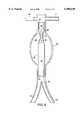
- FIG. 9is a side section view illustrating the aortic aneurysm of FIG. 8 after a split-leg graft has been inserted above the bifurcation of the aorta;
- FIG. 10is a side section view illustrating the aneurysm and graft of FIG. 9 after an angioplasty balloon is used to expand a stent in the aorta above the aneurysm to secure the graft in place; and,
- FIG. 11is a side section view of the aneurysm and graft of FIG. 10 illustrating the insertion of a stent on one of the distal split legs of the graft to secure the graft in an iliac artery.
- a graft for carrying bloodincludes a first portion having a diameter; and, a second portion connected to said first portion and having a diameter less than the diameter of said first expanded portion.
- the second portionis expandable with a balloon after the second, along with the first, portion is inserted in a blood vessel in the body of an animal.
- Iprovide a graft for carrying blood.
- the graftincludes a first portion having a diameter; and, a second portion connected to said first portion and having an original diameter.
- the second portionis expandable with a balloon to a diameter greater than the original diameter after the second portion is inserted in a blood vessel in the body of an animal.
- Iprovide a method for inserting in the body of an animal a graft for carrying blood.
- the methodincludes the steps of providing a graft including a first portion having a diameter, and a second portion connected to the first portion and having a diameter less than the diameter of the first portion, the second portion being expandable with a balloon after the second portion is inserted in a blood vessel in the body of an animal; inserting the second portion in the blood vessel of an animal; and, expanding the second portion with a balloon.
- Iprovide a method for inserting in a human being a graft which extends into the aortic blood vessel bifurcation.
- the methodincludes the step of providing a graft.
- the graftincludes a center portion having a pair of ends and a diameter; a first expandable portion connected to one end of the center portion; a first expandable leg connected to the other end of the center portion; and, a second expandable leg connected to the other end of said center portion.
- a portion of one end of a first length of sutureis inserted through one side of the groin of the patient, through one iliac artery, through the other iliac artery, and out the other side of the groin of the patient such that the other end of said suture extends out through said one side of the groin.
- a portion of the suture extending out the other side of the groin of the patientis attached to the second expandable leg of the graft.
- a second length of sutureis attached to the first expandable leg.
- the graftis inserted into the aorta through said other side of the groin such that the first and second expandable legs move through the aorta toward the patient's heart and past the junction of iliac arteries.
- the first and second lengths of sutureare gently drawn in a direction out from the patient's body to move the graft away from the patient's heart such that the first and second expandable legs are each pulled down into one of the iliac arteries.
- the first expandable portion of the graftis expanded with a stent to secure the graft in place in the aorta.
- FIG. 1illustrates a graft 20 constructed in accordance with the invention.
- the diameter of center portion 21is greater than the diameter of the proximal portion 22 and distal portion 23.
- the graft 20is presently preferably made by taking a length of material like thin, pliable, expandable polytetrafluoroethylene (PTFE) tubing and expanding an intermediate section of the tubing to form center portion 21 while not expanding the proximal portion 22 and distal portion 23.
- PTFEpolytetrafluoroethylene
- Fabricating graft 20 from a thin, pliable, readily foldable materialis preferred because one primary application of the graft requires that the graft be folded into a small configuration so the graft can be inserted into a blood vessel in a sheath or sleeve which slides along a guide wire inserted in the blood vessel.
- the central portion 21can be made from a material different than the material used to make the proximal portion 22 and/or distal portion 23.
- Portion 22can be made of a material different from that of portions 21 and/or 23.
- Central portion 21also need not be expandable and can, for example, be fabricated from dacron, nylon or some other synthetic material which has a diameter larger than the diameter of the proximal and distal portions 22, 23 and which is not expandable.
- Central portion 21can be sutured or otherwise attached to the proximal portion 22 and/or distal portion 23.
- the diameter of portion 21is larger than the diameter of proximal and distal portions 22 and 23, and the diameter of portion 21 normally need not be increased after graft 20 is inserted in the body. Not having to increase the diameter of portion 21 after graft 20 is inserted in the body is an important advantage of the invention.
- the diameter of center portion 21can, if desired, be increased with a balloon if portion 21 is made from an expandable material. Regardless of the materials utilized to fabricate graft 20, it is preferred, and important, that the graft can be folded or compressed and reduced to a size which facilitates insertion of the graft through a sheath into the desired blood vessel in the body.
- diameterrefers to the outside diameter of the material used in the grafts of the invention.
- the grafts described hereinconsist of hollow cylindrical or substantially cylindrical portions.
- central portion 21, proximal portion 22, and distal portion 23are cylindrical hollow members.
- the graft 30 of FIG. 2is, like graft 20, presently preferably made by taking a length of thin, pliable, foldable, hollow PTFE tubing and expanding an intermediate section to form center portion 31.
- Center portion 31has a diameter greater than the proximal portion 32 and distal portion 33.
- the diameter of proximal portion 32equals that of the original, unexpanded PTFE tubing, i.e. portion 32 comprises unexpanded PTFE tubing.
- the distal portion 33is formed by expanding the PTFE tubing to a diameter which is greater than the diameter of portion 32 and less than the diameter of central portion 31.
- the diameter of distal portion 34 attached to opening 36is also greater than the diameter of proximal portion 32 and is less than the diameter of center portion 31.
- Portion 34is formed by expanding or pre-dilating hollow PTFE tubing. As discussed in connection with graft 20, portion 31 need not be made of an expandable material, can be made from a material different than that of portions 32 and 33, etc.
- the graft 40 of FIG. 3is, like grafts 20 and 30, presently preferably made by taking a length of thin, pliable, foldable, hollow PTFE tubing and expanding an end section of the tubing to form portion 41.
- Portion 41has a diameter greater than the proximal portion 42.
- portion 41need not be made of an expandable material, and can be made from a material different that of portion 42, etc.
- the graft 20 of FIG. 1is made by taking a length of two mm diameter PTFE tubing and expanding the center portion 21 to eight mm by introducing a balloon inside portion 21 and expanding the balloon with pressurized water.
- the diameter of proximal portion 22is two mm.
- the diameter of distal portion 23is two mm.
- the diameter of the pre-dilated center portion 21 in FIG. 1is, as noted, eight mm.
- Radio opaque marker 84is attached to proximal portion 22.
- Radio opaque marker 85is attached to distal portion 23.
- Stents 24 and 27are inserted in proximal portion 22 and distal portion 23, respectively.
- a balloon 25is introduced in stent 24 and is expanded to about one atmosphere pressure to secure the balloon 25 in place inside stent 24 without causing stent 24 to expand.
- the balloonis carried on shaft 26.
- the graft 20--stents 24, 27--balloon 25--shaft 26 of FIG. 1are tightly folded inside a sheath and inserted in a selected blood vessel about eight mm in diameter. Once the graft 20 is at the desired position in the blood vessel, balloon 25 is used to expand stent 24 and proximal portion 22 to about eight mm. After stent 24 is expanded, balloon 25 is deflated and moved to a position inside stent 27. Balloon 25 is expanded again to expand stent 27 and distal portion 23 to about eight mm.
- the graft 40 of FIG. 3is made by taking a length of five mm diameter expandable PTFE tubing and pre-expanding one end of the tubing to form the distal portion 41.
- Portion 41has a diameter of 18 mm.
- the proximal portion 42is not pre-expanded and has a diameter of five mm.
- a radiopaque marker 82is affixed to the proximal portion 42.
- Another radiopaque marker 83is affixed to distal portion 41.
- the distal portion 41is long enough to span an aneurysm in the procedure described below in this Example 2.
- a balloon expandable aortic stent 43is inserted in proximal end 42.
- a four cm long collapsed or folded angioplasty balloon 44is inserted in stent 43 in the manner shown in FIG. 4 and inflated to two to three atmospheres to secure the balloon in stent 43 and proximal portion 42.
- Balloon 44is carried on a guide wire 45. If the balloon is inflated standing alone outside of stent 43, it has an initial diameter of twenty cm after the balloon is filled sufficiently (to a pressure of about one atmosphere) to remove the folds from the balloon and assume a smooth arcuate configuration. As the pressure of water in the balloon is increased, the diameter of the balloon increases to its maximum labeled diameter.
- the stent 43is mounted in balloon 40 so that one end of stent 43 extends two mm outside the left hand end of proximal portion 42. If desired, stent 43 can be attached to proximal portion 42 with a single prolene suture or by any other desired means including a staple.
- an eighteen Fr. French sheathis used to introduce the graft 40--stent 43--balloon 44 configuration through the common femoral artery percutaneously and to the level of the neck of the aneurysm 50 below the renal arteries 51 and 52 as shown in FIG. 5.
- the sheathis retracted or pulled along guide wire 45 to a position in the iliac artery 53.
- the end of proximal portion 42is positioned in the proximal aneurysmal neck of the blood vessel.
- the end of distal portion 41is positioned above the aortoiliac bifurcation.
- the balloon 44is expanded to expand stent 43 to force proximal portion 42 against the aneurysmal neck of the blood vessel and fix the graft 40 in place.
- Stent 43 and portion 42are expanded to a diameter of about eighteen mm. Because of the high blood flow pressure through the aorta, a balloon is used to occlude the aorta from above while balloon 44 is expanded. Or, a steady pressure is applied to shaft 45 to hold balloon 44 in place during its inflation.
- proximal portion 42can include a tapered tip 42A and stent 43 can include a tapered tip 43A which are not expanded when balloon 44 is expanded in FIG. 5.
- balloon 44is deflated and moved upwardly in FIG. 5 into tapered tip 42A, where balloon 44 is again expanded to expand tip 43A and tip 42A to a diameter of about eighteen mm.
- balloon 44has been deflated and moved downwardly to a new position to expand the remaining unexpanded portion of proximal portion 43.
- balloon 44is expanded to expand the constricted section of proximal portion 43 to about eighteen mm.
- the proximal portion 43can be expanded to about eighteen mm because the balloon operator knows what balloon inflation pressure is required to expand the proximal portion 43 from five mm to eighteen mm and can view this procedure fluoroscopically.
- proximal portion 43is expanded to about eighteen mm along its entire length
- balloon 44is deflated and removed and, as shown in FIG. 7, an aortic stent 55 is deployed in the lower end of graft 40.
- a balloon 44is used to expand stent 55 to force the lower end of distal portion 41 against the wall of the blood vessel. Balloon 44 is then deflated, and balloon 44 and shaft 45 are removed from the patient's body.
- the graft 30 of FIG. 2is made by taking a length of five mm diameter expandable PTFE tubing and pre-expanding an intermediate portion of the tubing to form the central portion 31.
- Portion 31has a diameter of 20 mm.
- the proximal portion 32is not pre-expanded and has a diameter of five mm.
- the first distal portion 33is made by pre-dilating an end of the five mm tubing to nine mm with a nine mm angioplasty balloon catheter.
- Opening 36is formed through graft 30 and the end 35 of a length 34 of pre-expanded PTFE is securely sutured around opening 36.
- the opening 36is nine to ten mm wide and opens on the side of the graft.
- the anastomosisis from end to side.
- a size 4/0 PTFE, or similar material, continuous sutureis used for the anastomosis.
- Length 34comprises the second distal portion of the graft 30. Distal portion 34 is formed by pre-dilating a length of five mm diameter PTFE before portion 34 is sutured around opening 36.
- a radiopaque marker 81is affixed to the outer end of distal portion 33.
- Another radiopaque marker 80is affixed to the outer end of distal portion 34.
- a third radiopaque marker 86is affixed to the outer end of proximal portion 32.
- the central portion 31is long enough to span an aneurysm in the procedure described below in this Example 3.
- a balloon expandable aortic stent 43is inserted in proximal end 42.
- An aortic balloon expandable stentis inserted in the proximal end 32, followed by a twenty mm angioplasty balloon 65 (assuming the neck of the blood vessel above the aneurysm is about twenty mm in diameter).
- Balloon 65is positioned inside stent 66.
- the wire 64 carrying balloon 65extends from balloon 65 through center portion 31 and out through distal portion 34.
- the balloon 65is inflated to a pressure of one to three atmospheres in order to fix the balloon and stent in graft 30.
- the one to three atmosphere pressureis less than the pressure needed to expand stent 66 and the proximal portion 32.
- the end of the proximal portion 32is marked with a clip.
- the stent 66can be secured to portion 32 with one or two single protene sutures.
- a loop 62 of prolene sutureis introduced in a nine Fr. sheath 60 through the patient's right groin and is passed through iliac artery 54, through artery 53, through the eighteen Fr. sheath 61, and out through the patients left groin in the manner illustrated in FIG. 8.
- the end of loop 62 extending out of the patient's left groinis secured to the end of distal portion 33.
- Another loop 63 of sutureis secured to the end of distal portion 34.
- the graft 30--stent 66--balloon 65is reduced or compressed into sheath 61 for the percutaneous introduction through artery 53 into the aorta of the patient.
- sheath 61is withdrawn into the iliac artery 53 and graft 30 is positioned in the aorta with distal portions 33 and 34 above the aortic bifurcation as shown in FIG. 9.
- radiopaque markers 80, 81, 86permit the ready location of the graft 30 in the patient.
- loop 62extends from distal portion 33 out through the right groin of the patient.
- Loop 63extends from distal portion 34 out through the left groin of the patient.
- loops 62 and 63are gently pulled to displace graft 30 in the direction of arrow A in FIG. 9 and to move distal portion 33 into artery 54 and distal portion 34 into artery 53 so that graft 30 assumes the general position illustrated in FIG. 10.
- FIG. 10illustrates stent 66 and proximal portion 32 after balloon 65 has been inflated to expand stent 66 and after balloon 65 has then been deflated and moved downwardly into the remaining unexpanded portion of proximal portion 32.
- stent 66, portion 32, and/or balloon 65can be sized such that after balloon 65 is inflated to expand stent 66, the entire length of portion 32 is expanded.
- portion 32is expanded to a diameter approximately equal to the diameter of central portion 31.
- portion 32is expanded and balloon 65 is deflated, the blood flow through the aorta helps to open distal portions 33 and 34.
- Balloon 65 and shaft 64are removed from the patient. Loops 62 and 63 are removed. Stent 72 is inserted in distal portion 34 in the position shown in FIG. 11 and is expanded with balloon 71 on shaft 70 to secure portion 34 in artery 53. A similar stent is inserted in the lower end of distal portion 33 and is expanded to secure portion 33 in artery 54.
- the expandable stents shown in FIGS. 1, 4 to 7, and 9 to 11can be positioned inside a graft, outside of the graft, or intermediate layers of graft material when the graft is made from laminate cylindrical members.
- Many kinds of expandable stentsare known in the art and will not be detailed herein. While it is possible that a self expanding stent could be utilized in the practice of the invention, it is presently preferred that balloon expandable stents be utilized to insure that the stents securely anchor a graft to a blood vessel.
Landscapes
- Health & Medical Sciences (AREA)
- Engineering & Computer Science (AREA)
- Biomedical Technology (AREA)
- General Health & Medical Sciences (AREA)
- Public Health (AREA)
- Veterinary Medicine (AREA)
- Animal Behavior & Ethology (AREA)
- Life Sciences & Earth Sciences (AREA)
- Heart & Thoracic Surgery (AREA)
- Vascular Medicine (AREA)
- Cardiology (AREA)
- Oral & Maxillofacial Surgery (AREA)
- Transplantation (AREA)
- Pulmonology (AREA)
- Gastroenterology & Hepatology (AREA)
- Anesthesiology (AREA)
- Hematology (AREA)
- Prostheses (AREA)
- Medicines Containing Plant Substances (AREA)
Abstract
Description
Claims (6)
Priority Applications (1)
| Application Number | Priority Date | Filing Date | Title |
|---|---|---|---|
| US08/885,626US6098630A (en) | 1994-06-13 | 1997-06-30 | Multiple diameter expandable graft for blood vessel and method for deploying the same |
Applications Claiming Priority (3)
| Application Number | Priority Date | Filing Date | Title |
|---|---|---|---|
| US25872894A | 1994-06-13 | 1994-06-13 | |
| US57905495A | 1995-12-21 | 1995-12-21 | |
| US08/885,626US6098630A (en) | 1994-06-13 | 1997-06-30 | Multiple diameter expandable graft for blood vessel and method for deploying the same |
Related Parent Applications (1)
| Application Number | Title | Priority Date | Filing Date |
|---|---|---|---|
| US57905495AContinuation | 1994-06-13 | 1995-12-21 |
Publications (1)
| Publication Number | Publication Date |
|---|---|
| US6098630Atrue US6098630A (en) | 2000-08-08 |
Family
ID=22981877
Family Applications (1)
| Application Number | Title | Priority Date | Filing Date |
|---|---|---|---|
| US08/885,626Expired - LifetimeUS6098630A (en) | 1994-06-13 | 1997-06-30 | Multiple diameter expandable graft for blood vessel and method for deploying the same |
Country Status (7)
| Country | Link |
|---|---|
| US (1) | US6098630A (en) |
| EP (1) | EP0766539B1 (en) |
| JP (1) | JP3662255B2 (en) |
| AT (1) | ATE240694T1 (en) |
| DE (1) | DE69530842T2 (en) |
| ES (1) | ES2199993T3 (en) |
| WO (1) | WO1995034255A1 (en) |
Cited By (26)
| Publication number | Priority date | Publication date | Assignee | Title |
|---|---|---|---|---|
| US6395019B2 (en) | 1998-02-09 | 2002-05-28 | Trivascular, Inc. | Endovascular graft |
| US20020156523A1 (en)* | 1994-08-31 | 2002-10-24 | Lilip Lau | Exterior supported self-expanding stent-graft |
| US20020165603A1 (en)* | 1996-12-23 | 2002-11-07 | Troy Thornton | Kink-resistant bifurcated prosthesis |
| US20030055484A1 (en)* | 1994-08-31 | 2003-03-20 | Lilip Lau | Exterior supported self-expanding stent-graft |
| US6585762B1 (en)* | 2000-08-10 | 2003-07-01 | Paul Stanish | Arteriovenous grafts and methods of implanting the same |
| US20040073282A1 (en)* | 2001-08-06 | 2004-04-15 | Paul Stanish | Distally-narrowed vascular grafts and methods of using same for making artery-to-vein and artery-to-artery connections |
| US6733521B2 (en) | 2001-04-11 | 2004-05-11 | Trivascular, Inc. | Delivery system and method for endovascular graft |
| US6761733B2 (en) | 2001-04-11 | 2004-07-13 | Trivascular, Inc. | Delivery system and method for bifurcated endovascular graft |
| US20060116478A1 (en)* | 2000-08-11 | 2006-06-01 | Chen John C | Bi-modal ionomers |
| US7066951B2 (en) | 2000-02-02 | 2006-06-27 | Trivascular, Inc. | Delivery system and method for expandable intracorporeal device |
| US7147661B2 (en) | 2001-12-20 | 2006-12-12 | Boston Scientific Santa Rosa Corp. | Radially expandable stent |
| US7147660B2 (en) | 2001-12-20 | 2006-12-12 | Boston Scientific Santa Rosa Corp. | Advanced endovascular graft |
| US7803178B2 (en) | 2004-01-30 | 2010-09-28 | Trivascular, Inc. | Inflatable porous implants and methods for drug delivery |
| US7901449B2 (en) | 1994-02-09 | 2011-03-08 | Scimed Life Systems, Inc. | Bifurcated endoluminal prosthesis |
| US8066755B2 (en) | 2007-09-26 | 2011-11-29 | Trivascular, Inc. | System and method of pivoted stent deployment |
| US8083789B2 (en) | 2007-11-16 | 2011-12-27 | Trivascular, Inc. | Securement assembly and method for expandable endovascular device |
| US8226701B2 (en) | 2007-09-26 | 2012-07-24 | Trivascular, Inc. | Stent and delivery system for deployment thereof |
| US8241346B2 (en) | 2001-12-20 | 2012-08-14 | Trivascular, Inc. | Endovascular graft and method of delivery |
| US8323328B2 (en) | 1995-12-14 | 2012-12-04 | W. L. Gore & Associates, Inc. | Kink resistant stent-graft |
| US8328861B2 (en) | 2007-11-16 | 2012-12-11 | Trivascular, Inc. | Delivery system and method for bifurcated graft |
| US8663309B2 (en) | 2007-09-26 | 2014-03-04 | Trivascular, Inc. | Asymmetric stent apparatus and method |
| US8992595B2 (en) | 2012-04-04 | 2015-03-31 | Trivascular, Inc. | Durable stent graft with tapered struts and stable delivery methods and devices |
| US20160175569A1 (en)* | 2014-12-22 | 2016-06-23 | Richard R. Heuser | Device for treating vascular occlusion |
| US9498363B2 (en) | 2012-04-06 | 2016-11-22 | Trivascular, Inc. | Delivery catheter for endovascular device |
| US10159557B2 (en) | 2007-10-04 | 2018-12-25 | Trivascular, Inc. | Modular vascular graft for low profile percutaneous delivery |
| US10888414B2 (en) | 2019-03-20 | 2021-01-12 | inQB8 Medical Technologies, LLC | Aortic dissection implant |
Families Citing this family (29)
| Publication number | Priority date | Publication date | Assignee | Title |
|---|---|---|---|---|
| ES2135520T3 (en)* | 1993-11-04 | 1999-11-01 | Bard Inc C R | NON-MIGRANT VASCULAR PROSTHESIS. |
| US5824044A (en) | 1994-05-12 | 1998-10-20 | Endovascular Technologies, Inc. | Bifurcated multicapsule intraluminal grafting system |
| WO1996036297A1 (en) | 1995-05-19 | 1996-11-21 | Kanji Inoue | Transplantation instrument, method of bending same and method of transplanting same |
| US5769882A (en)* | 1995-09-08 | 1998-06-23 | Medtronic, Inc. | Methods and apparatus for conformably sealing prostheses within body lumens |
| US5824037A (en)* | 1995-10-03 | 1998-10-20 | Medtronic, Inc. | Modular intraluminal prostheses construction and methods |
| US6193745B1 (en)* | 1995-10-03 | 2001-02-27 | Medtronic, Inc. | Modular intraluminal prosteheses construction and methods |
| US6576009B2 (en) | 1995-12-01 | 2003-06-10 | Medtronic Ave, Inc. | Bifurcated intraluminal prostheses construction and methods |
| US5824040A (en)* | 1995-12-01 | 1998-10-20 | Medtronic, Inc. | Endoluminal prostheses and therapies for highly variable body lumens |
| US5843158A (en)* | 1996-01-05 | 1998-12-01 | Medtronic, Inc. | Limited expansion endoluminal prostheses and methods for their use |
| ATE290832T1 (en) | 1996-01-05 | 2005-04-15 | Medtronic Inc | EXPANDABLE ENDOLUMINAL PROSTHESES |
| CA2245897C (en) | 1996-02-28 | 2004-12-14 | Impra, Inc. | Flanged graft for end-to-side anastomosis |
| US5755773A (en)* | 1996-06-04 | 1998-05-26 | Medtronic, Inc. | Endoluminal prosthetic bifurcation shunt |
| US5860998A (en)* | 1996-11-25 | 1999-01-19 | C. R. Bard, Inc. | Deployment device for tubular expandable prosthesis |
| US6364901B1 (en) | 1996-12-20 | 2002-04-02 | Kanji Inoue | Appliance collapsible for insertion into a human organ and capable of resilient restoration |
| JP4042998B2 (en) | 1997-01-29 | 2008-02-06 | クック インコーポレイテッド | Bell bottom modular stent graft |
| GB9709967D0 (en)* | 1997-05-17 | 1997-07-09 | Harris Peter L | Prosthetic grafts |
| US6102938A (en)* | 1997-06-17 | 2000-08-15 | Medtronic Inc. | Endoluminal prosthetic bifurcation shunt |
| US7208010B2 (en) | 2000-10-16 | 2007-04-24 | Conor Medsystems, Inc. | Expandable medical device for delivery of beneficial agent |
| US20040254635A1 (en) | 1998-03-30 | 2004-12-16 | Shanley John F. | Expandable medical device for delivery of beneficial agent |
| US6241762B1 (en) | 1998-03-30 | 2001-06-05 | Conor Medsystems, Inc. | Expandable medical device with ductile hinges |
| US6537284B1 (en) | 1998-10-29 | 2003-03-25 | Kanji Inoue | Device for guiding an appliance |
| US6293967B1 (en)* | 1998-10-29 | 2001-09-25 | Conor Medsystems, Inc. | Expandable medical device with ductile hinges |
| EP1095635A4 (en) | 1999-05-06 | 2007-06-20 | Kanji Inoue | Apparatus for folding instrument and use of the same apparatus |
| US6514282B1 (en) | 1999-10-04 | 2003-02-04 | Kanji Inoue | Method of folding transplanting instrument and transplanting instrument |
| EP1498084B1 (en) | 2000-10-16 | 2014-06-18 | Innovational Holdings, LLC | Expandable medical device for delivery of beneficial agent |
| US6607539B1 (en) | 2001-05-18 | 2003-08-19 | Endovascular Technologies, Inc. | Electric endovascular implant depolyment system |
| US7842083B2 (en) | 2001-08-20 | 2010-11-30 | Innovational Holdings, Llc. | Expandable medical device with improved spatial distribution |
| US20050273150A1 (en)* | 2004-03-31 | 2005-12-08 | Howell Douglas D | Stent introducer system |
| US8709069B2 (en) | 2005-07-01 | 2014-04-29 | C. R. Bard, Inc. | Flanged graft with trim lines |
Citations (34)
| Publication number | Priority date | Publication date | Assignee | Title |
|---|---|---|---|---|
| US3008187A (en)* | 1959-01-05 | 1961-11-14 | Raybestos Manhattan Inc | Method and apparatus for extruding polytetrafluoroethylene tubing |
| US4110392A (en)* | 1976-12-17 | 1978-08-29 | W. L. Gore & Associates, Inc. | Production of porous sintered PTFE products |
| US4250138A (en)* | 1976-09-13 | 1981-02-10 | Sumitomo Electric Industries, Ltd. | Process for producing microporous tubes of polytetrafluoroethylene |
| US4441215A (en)* | 1980-11-17 | 1984-04-10 | Kaster Robert L | Vascular graft |
| US4482516A (en)* | 1982-09-10 | 1984-11-13 | W. L. Gore & Associates, Inc. | Process for producing a high strength porous polytetrafluoroethylene product having a coarse microstructure |
| US4733665A (en)* | 1985-11-07 | 1988-03-29 | Expandable Grafts Partnership | Expandable intraluminal graft, and method and apparatus for implanting an expandable intraluminal graft |
| US4743251A (en)* | 1983-12-08 | 1988-05-10 | Henry Bocquee | Vein prothesis and method for producing same |
| EP0267719A2 (en)* | 1986-11-13 | 1988-05-18 | W.L. Gore & Associates, Inc. | Method for extruding and expanding polytetrafluoroethylene tubing and the products produced thereby |
| EP0269449A2 (en)* | 1986-11-26 | 1988-06-01 | BAXTER INTERNATIONAL INC. (a Delaware corporation) | Porous flexible radially expanded fluoropolymers and process for producing the same |
| US4856516A (en)* | 1989-01-09 | 1989-08-15 | Cordis Corporation | Endovascular stent apparatus and method |
| US4922905A (en)* | 1985-11-30 | 1990-05-08 | Strecker Ernst P | Dilatation catheter |
| US4955859A (en)* | 1989-07-07 | 1990-09-11 | C. R. Bard, Inc. | High-friction prostatic stent |
| US4994071A (en)* | 1989-05-22 | 1991-02-19 | Cordis Corporation | Bifurcating stent apparatus and method |
| WO1991012779A1 (en)* | 1990-02-28 | 1991-09-05 | Medtronic, Inc. | Intralumenal drug eluting prosthesis |
| US5061275A (en)* | 1986-04-21 | 1991-10-29 | Medinvent S.A. | Self-expanding prosthesis |
| US5061276A (en)* | 1987-04-28 | 1991-10-29 | Baxter International Inc. | Multi-layered poly(tetrafluoroethylene)/elastomer materials useful for in vivo implantation |
| US5071609A (en)* | 1986-11-26 | 1991-12-10 | Baxter International Inc. | Process of manufacturing porous multi-expanded fluoropolymers |
| EP0461791A1 (en)* | 1990-06-11 | 1991-12-18 | Hector D. Barone | Aortic graft and apparatus for repairing an abdominal aortic aneurysm |
| US5078726A (en)* | 1989-02-01 | 1992-01-07 | Kreamer Jeffry W | Graft stent and method of repairing blood vessels |
| US5108424A (en)* | 1984-01-30 | 1992-04-28 | Meadox Medicals, Inc. | Collagen-impregnated dacron graft |
| US5122154A (en)* | 1990-08-15 | 1992-06-16 | Rhodes Valentine J | Endovascular bypass graft |
| US5123917A (en)* | 1990-04-27 | 1992-06-23 | Lee Peter Y | Expandable intraluminal vascular graft |
| US5217483A (en)* | 1990-11-28 | 1993-06-08 | Numed, Inc. | Intravascular radially expandable stent |
| US5219355A (en)* | 1990-10-03 | 1993-06-15 | Parodi Juan C | Balloon device for implanting an aortic intraluminal prosthesis for repairing aneurysms |
| EP0551179A1 (en)* | 1992-01-08 | 1993-07-14 | Expandable Grafts Partnership | Method and apparatus for bilateral intra-aortic bypass |
| US5258020A (en)* | 1990-09-14 | 1993-11-02 | Michael Froix | Method of using expandable polymeric stent with memory |
| WO1994001056A1 (en)* | 1992-07-13 | 1994-01-20 | Boston Scientific Corporation | Tubular medical prosthesis |
| WO1994012136A1 (en)* | 1992-10-13 | 1994-06-09 | Boston Scientific Corporation | Stents for body lumens exhibiting peristaltic |
| WO1994013224A1 (en)* | 1992-12-11 | 1994-06-23 | W.L. Gore & Associates, Inc. | A prosthetic vascular graft |
| US5360443A (en)* | 1990-06-11 | 1994-11-01 | Barone Hector D | Aortic graft for repairing an abdominal aortic aneurysm |
| US5383928A (en)* | 1992-06-10 | 1995-01-24 | Emory University | Stent sheath for local drug delivery |
| US5425765A (en)* | 1993-06-25 | 1995-06-20 | Tiefenbrun; Jonathan | Surgical bypass method |
| US5667486A (en)* | 1993-04-27 | 1997-09-16 | Ams Medinvent, S.A. | Prostatic stent |
| US5693087A (en)* | 1990-06-11 | 1997-12-02 | Parodi; Juan C. | Method for repairing an abdominal aortic aneurysm |
Family Cites Families (2)
| Publication number | Priority date | Publication date | Assignee | Title |
|---|---|---|---|---|
| US4577631A (en)* | 1984-11-16 | 1986-03-25 | Kreamer Jeffry W | Aneurysm repair apparatus and method |
| US5476506A (en)* | 1994-02-08 | 1995-12-19 | Ethicon, Inc. | Bi-directional crimped graft |
- 1995
- 1995-06-07DEDE69530842Tpatent/DE69530842T2/ennot_activeExpired - Fee Related
- 1995-06-07JPJP50232696Apatent/JP3662255B2/ennot_activeExpired - Fee Related
- 1995-06-07ATAT95921622Tpatent/ATE240694T1/ennot_activeIP Right Cessation
- 1995-06-07EPEP95921622Apatent/EP0766539B1/ennot_activeExpired - Lifetime
- 1995-06-07WOPCT/US1995/007258patent/WO1995034255A1/enactiveIP Right Grant
- 1995-06-07ESES95921622Tpatent/ES2199993T3/ennot_activeExpired - Lifetime
- 1997
- 1997-06-30USUS08/885,626patent/US6098630A/ennot_activeExpired - Lifetime
Patent Citations (41)
| Publication number | Priority date | Publication date | Assignee | Title |
|---|---|---|---|---|
| US3008187A (en)* | 1959-01-05 | 1961-11-14 | Raybestos Manhattan Inc | Method and apparatus for extruding polytetrafluoroethylene tubing |
| US4250138A (en)* | 1976-09-13 | 1981-02-10 | Sumitomo Electric Industries, Ltd. | Process for producing microporous tubes of polytetrafluoroethylene |
| US4110392A (en)* | 1976-12-17 | 1978-08-29 | W. L. Gore & Associates, Inc. | Production of porous sintered PTFE products |
| US4441215A (en)* | 1980-11-17 | 1984-04-10 | Kaster Robert L | Vascular graft |
| US4482516A (en)* | 1982-09-10 | 1984-11-13 | W. L. Gore & Associates, Inc. | Process for producing a high strength porous polytetrafluoroethylene product having a coarse microstructure |
| US4743251A (en)* | 1983-12-08 | 1988-05-10 | Henry Bocquee | Vein prothesis and method for producing same |
| US5108424A (en)* | 1984-01-30 | 1992-04-28 | Meadox Medicals, Inc. | Collagen-impregnated dacron graft |
| US4733665C2 (en)* | 1985-11-07 | 2002-01-29 | Expandable Grafts Partnership | Expandable intraluminal graft and method and apparatus for implanting an expandable intraluminal graft |
| US4776337A (en)* | 1985-11-07 | 1988-10-11 | Expandable Grafts Partnership | Expandable intraluminal graft, and method and apparatus for implanting an expandable intraluminal graft |
| US4776337B1 (en)* | 1985-11-07 | 2000-12-05 | Cordis Corp | Expandable intraluminal graft and method and apparatus for implanting an expandable intraluminal graft |
| US4733665B1 (en)* | 1985-11-07 | 1994-01-11 | Expandable Grafts Partnership | Expandable intraluminal graft,and method and apparatus for implanting an expandable intraluminal graft |
| US4733665A (en)* | 1985-11-07 | 1988-03-29 | Expandable Grafts Partnership | Expandable intraluminal graft, and method and apparatus for implanting an expandable intraluminal graft |
| US4922905A (en)* | 1985-11-30 | 1990-05-08 | Strecker Ernst P | Dilatation catheter |
| US5061275A (en)* | 1986-04-21 | 1991-10-29 | Medinvent S.A. | Self-expanding prosthesis |
| EP0267719A2 (en)* | 1986-11-13 | 1988-05-18 | W.L. Gore & Associates, Inc. | Method for extruding and expanding polytetrafluoroethylene tubing and the products produced thereby |
| EP0269449A2 (en)* | 1986-11-26 | 1988-06-01 | BAXTER INTERNATIONAL INC. (a Delaware corporation) | Porous flexible radially expanded fluoropolymers and process for producing the same |
| US5071609A (en)* | 1986-11-26 | 1991-12-10 | Baxter International Inc. | Process of manufacturing porous multi-expanded fluoropolymers |
| US5061276A (en)* | 1987-04-28 | 1991-10-29 | Baxter International Inc. | Multi-layered poly(tetrafluoroethylene)/elastomer materials useful for in vivo implantation |
| US4856516A (en)* | 1989-01-09 | 1989-08-15 | Cordis Corporation | Endovascular stent apparatus and method |
| US5078726A (en)* | 1989-02-01 | 1992-01-07 | Kreamer Jeffry W | Graft stent and method of repairing blood vessels |
| US4994071A (en)* | 1989-05-22 | 1991-02-19 | Cordis Corporation | Bifurcating stent apparatus and method |
| US4955859A (en)* | 1989-07-07 | 1990-09-11 | C. R. Bard, Inc. | High-friction prostatic stent |
| WO1991000712A2 (en)* | 1989-07-07 | 1991-01-24 | C.R. Bard, Inc. | High-friction prostatic stent |
| WO1991012779A1 (en)* | 1990-02-28 | 1991-09-05 | Medtronic, Inc. | Intralumenal drug eluting prosthesis |
| US5123917A (en)* | 1990-04-27 | 1992-06-23 | Lee Peter Y | Expandable intraluminal vascular graft |
| US5360443A (en)* | 1990-06-11 | 1994-11-01 | Barone Hector D | Aortic graft for repairing an abdominal aortic aneurysm |
| EP0461791A1 (en)* | 1990-06-11 | 1991-12-18 | Hector D. Barone | Aortic graft and apparatus for repairing an abdominal aortic aneurysm |
| US5693087A (en)* | 1990-06-11 | 1997-12-02 | Parodi; Juan C. | Method for repairing an abdominal aortic aneurysm |
| US5122154A (en)* | 1990-08-15 | 1992-06-16 | Rhodes Valentine J | Endovascular bypass graft |
| US5258020A (en)* | 1990-09-14 | 1993-11-02 | Michael Froix | Method of using expandable polymeric stent with memory |
| US5219355A (en)* | 1990-10-03 | 1993-06-15 | Parodi Juan C | Balloon device for implanting an aortic intraluminal prosthesis for repairing aneurysms |
| US5217483A (en)* | 1990-11-28 | 1993-06-08 | Numed, Inc. | Intravascular radially expandable stent |
| US5316023A (en)* | 1992-01-08 | 1994-05-31 | Expandable Grafts Partnership | Method for bilateral intra-aortic bypass |
| EP0551179A1 (en)* | 1992-01-08 | 1993-07-14 | Expandable Grafts Partnership | Method and apparatus for bilateral intra-aortic bypass |
| US5366504A (en)* | 1992-05-20 | 1994-11-22 | Boston Scientific Corporation | Tubular medical prosthesis |
| US5383928A (en)* | 1992-06-10 | 1995-01-24 | Emory University | Stent sheath for local drug delivery |
| WO1994001056A1 (en)* | 1992-07-13 | 1994-01-20 | Boston Scientific Corporation | Tubular medical prosthesis |
| WO1994012136A1 (en)* | 1992-10-13 | 1994-06-09 | Boston Scientific Corporation | Stents for body lumens exhibiting peristaltic |
| WO1994013224A1 (en)* | 1992-12-11 | 1994-06-23 | W.L. Gore & Associates, Inc. | A prosthetic vascular graft |
| US5667486A (en)* | 1993-04-27 | 1997-09-16 | Ams Medinvent, S.A. | Prostatic stent |
| US5425765A (en)* | 1993-06-25 | 1995-06-20 | Tiefenbrun; Jonathan | Surgical bypass method |
Non-Patent Citations (2)
| Title |
|---|
| Palmaz, "Uses of Balloon Expandable Stents in Combination with PTFE" W.B. Saunders Company, Ltd., pp. 36-42, 1994. |
| Palmaz, Uses of Balloon Expandable Stents in Combination with PTFE W.B. Saunders Company, Ltd., pp. 36 42, 1994.* |
Cited By (41)
| Publication number | Priority date | Publication date | Assignee | Title |
|---|---|---|---|---|
| US7942919B2 (en) | 1994-02-09 | 2011-05-17 | Scimed Life Systems, Inc. | Bifurcated endoluminal prosthesis |
| US7901449B2 (en) | 1994-02-09 | 2011-03-08 | Scimed Life Systems, Inc. | Bifurcated endoluminal prosthesis |
| US20020156523A1 (en)* | 1994-08-31 | 2002-10-24 | Lilip Lau | Exterior supported self-expanding stent-graft |
| US20030055484A1 (en)* | 1994-08-31 | 2003-03-20 | Lilip Lau | Exterior supported self-expanding stent-graft |
| US8623065B2 (en) | 1994-08-31 | 2014-01-07 | W. L. Gore & Associates, Inc. | Exterior supported self-expanding stent-graft |
| US8323328B2 (en) | 1995-12-14 | 2012-12-04 | W. L. Gore & Associates, Inc. | Kink resistant stent-graft |
| US7682380B2 (en) | 1996-12-23 | 2010-03-23 | Gore Enterprise Holdings, Inc. | Kink-resistant bifurcated prosthesis |
| US20020165603A1 (en)* | 1996-12-23 | 2002-11-07 | Troy Thornton | Kink-resistant bifurcated prosthesis |
| US8801769B2 (en) | 1998-02-09 | 2014-08-12 | Trivascular, Inc. | Endovascular graft |
| US10548750B2 (en) | 1998-02-09 | 2020-02-04 | Trivascular, Inc. | Endovascular graft |
| US7081129B2 (en) | 1998-02-09 | 2006-07-25 | Boston Scientific Santa Rosa Corp. | Endovascular graft |
| US6395019B2 (en) | 1998-02-09 | 2002-05-28 | Trivascular, Inc. | Endovascular graft |
| US9867727B2 (en) | 1998-02-09 | 2018-01-16 | Trivascular, Inc. | Endovascular graft |
| US8361136B2 (en) | 1998-02-09 | 2013-01-29 | Trivascular, Inc. | Endovascular graft |
| US7615071B2 (en) | 1998-02-09 | 2009-11-10 | Trivascular2, Inc. | Endovascular graft |
| US7338518B2 (en) | 2000-02-02 | 2008-03-04 | Boston Scientific Santa Rosa Corp. | Delivery system and method for expandable intracorporeal device |
| US7066951B2 (en) | 2000-02-02 | 2006-06-27 | Trivascular, Inc. | Delivery system and method for expandable intracorporeal device |
| US6585762B1 (en)* | 2000-08-10 | 2003-07-01 | Paul Stanish | Arteriovenous grafts and methods of implanting the same |
| US20060116478A1 (en)* | 2000-08-11 | 2006-06-01 | Chen John C | Bi-modal ionomers |
| US6761733B2 (en) | 2001-04-11 | 2004-07-13 | Trivascular, Inc. | Delivery system and method for bifurcated endovascular graft |
| US6733521B2 (en) | 2001-04-11 | 2004-05-11 | Trivascular, Inc. | Delivery system and method for endovascular graft |
| US20040073282A1 (en)* | 2001-08-06 | 2004-04-15 | Paul Stanish | Distally-narrowed vascular grafts and methods of using same for making artery-to-vein and artery-to-artery connections |
| US7766954B2 (en) | 2001-12-20 | 2010-08-03 | Trivascular2, Inc. | Advanced endovascular graft |
| US7147660B2 (en) | 2001-12-20 | 2006-12-12 | Boston Scientific Santa Rosa Corp. | Advanced endovascular graft |
| US8864814B2 (en) | 2001-12-20 | 2014-10-21 | Trivascular, Inc. | Method of delivering advanced endovascular graft and system |
| US8241346B2 (en) | 2001-12-20 | 2012-08-14 | Trivascular, Inc. | Endovascular graft and method of delivery |
| US7147661B2 (en) | 2001-12-20 | 2006-12-12 | Boston Scientific Santa Rosa Corp. | Radially expandable stent |
| US7803178B2 (en) | 2004-01-30 | 2010-09-28 | Trivascular, Inc. | Inflatable porous implants and methods for drug delivery |
| US8267989B2 (en) | 2004-01-30 | 2012-09-18 | Trivascular, Inc. | Inflatable porous implants and methods for drug delivery |
| US8066755B2 (en) | 2007-09-26 | 2011-11-29 | Trivascular, Inc. | System and method of pivoted stent deployment |
| US8663309B2 (en) | 2007-09-26 | 2014-03-04 | Trivascular, Inc. | Asymmetric stent apparatus and method |
| US8226701B2 (en) | 2007-09-26 | 2012-07-24 | Trivascular, Inc. | Stent and delivery system for deployment thereof |
| US10159557B2 (en) | 2007-10-04 | 2018-12-25 | Trivascular, Inc. | Modular vascular graft for low profile percutaneous delivery |
| US10682222B2 (en) | 2007-10-04 | 2020-06-16 | Trivascular, Inc. | Modular vascular graft for low profile percutaneous delivery |
| US12016766B2 (en) | 2007-10-04 | 2024-06-25 | Trivascular, Inc. | Modular vascular graft for low profile percutaneous delivery |
| US8083789B2 (en) | 2007-11-16 | 2011-12-27 | Trivascular, Inc. | Securement assembly and method for expandable endovascular device |
| US8328861B2 (en) | 2007-11-16 | 2012-12-11 | Trivascular, Inc. | Delivery system and method for bifurcated graft |
| US8992595B2 (en) | 2012-04-04 | 2015-03-31 | Trivascular, Inc. | Durable stent graft with tapered struts and stable delivery methods and devices |
| US9498363B2 (en) | 2012-04-06 | 2016-11-22 | Trivascular, Inc. | Delivery catheter for endovascular device |
| US20160175569A1 (en)* | 2014-12-22 | 2016-06-23 | Richard R. Heuser | Device for treating vascular occlusion |
| US10888414B2 (en) | 2019-03-20 | 2021-01-12 | inQB8 Medical Technologies, LLC | Aortic dissection implant |
Also Published As
| Publication number | Publication date |
|---|---|
| WO1995034255A1 (en) | 1995-12-21 |
| EP0766539A1 (en) | 1997-04-09 |
| DE69530842D1 (en) | 2003-06-26 |
| JP3662255B2 (en) | 2005-06-22 |
| EP0766539A4 (en) | 1998-01-07 |
| JPH10506292A (en) | 1998-06-23 |
| DE69530842T2 (en) | 2004-01-22 |
| EP0766539B1 (en) | 2003-05-21 |
| ES2199993T3 (en) | 2004-03-01 |
| ATE240694T1 (en) | 2003-06-15 |
Similar Documents
| Publication | Publication Date | Title |
|---|---|---|
| US6098630A (en) | Multiple diameter expandable graft for blood vessel and method for deploying the same | |
| US6045557A (en) | Delivery catheter and method for positioning an intraluminal graft | |
| CA2202443C (en) | Method and apparatus for implanting a prosthesis within a body passageway | |
| CA2435304C (en) | Introducer for deployment of branched prosthesis | |
| EP1515668B1 (en) | Implantable prosthesis | |
| US5290305A (en) | Appliance collapsible for insertion into human organs and capable of resilient restoration | |
| US8192482B2 (en) | Endoluminal stent | |
| US6451053B1 (en) | Methods and apparatus for intraluminal placement of a bifurcated intraluminal graft | |
| US5242452A (en) | Device for collapsing an appliance collapsible for insertion into human organs | |
| US5755735A (en) | Bifurcated stent and method of making same | |
| US20060206190A1 (en) | Balloon catheter for multiple adjustable-length stent deployment | |
| US20010056295A1 (en) | Delivery system | |
| AU2002236790A1 (en) | Introducer for deployment of branched prosthesis | |
| US20010029383A1 (en) | Connecting apparatus and method | |
| CA2192974C (en) | Expandable endovascular graft and method for deploying the same |
Legal Events
| Date | Code | Title | Description |
|---|---|---|---|
| STCF | Information on status: patent grant | Free format text:PATENTED CASE | |
| REMI | Maintenance fee reminder mailed | ||
| REIN | Reinstatement after maintenance fee payment confirmed | ||
| FP | Lapsed due to failure to pay maintenance fee | Effective date:20040808 | |
| FEPP | Fee payment procedure | Free format text:PETITION RELATED TO MAINTENANCE FEES FILED (ORIGINAL EVENT CODE: PMFP); ENTITY STATUS OF PATENT OWNER: SMALL ENTITY | |
| FEPP | Fee payment procedure | Free format text:PAYOR NUMBER ASSIGNED (ORIGINAL EVENT CODE: ASPN); ENTITY STATUS OF PATENT OWNER: SMALL ENTITY | |
| FEPP | Fee payment procedure | Free format text:PETITION RELATED TO MAINTENANCE FEES GRANTED (ORIGINAL EVENT CODE: PMFG); ENTITY STATUS OF PATENT OWNER: SMALL ENTITY | |
| AS | Assignment | Owner name:LEMAITRE VASCULAR, INC., MASSACHUSETTS Free format text:SECURITY INTEREST;ASSIGNOR:ENDOMED, INC.;REEL/FRAME:015509/0082 Effective date:20041229 | |
| FPAY | Fee payment | Year of fee payment:4 | |
| SULP | Surcharge for late payment | ||
| AS | Assignment | Owner name:LEMAITRE ACQUISITION LLC, MASSACHUSETTS Free format text:ASSIGNMENT OF ASSIGNORS INTEREST;ASSIGNOR:ENDOMED, INC.;REEL/FRAME:015711/0478 Effective date:20050202 | |
| AS | Assignment | Owner name:ENDOMED, INC., ARIZONA Free format text:RELEASE OF SECURITY INTEREST IN PATENTS;ASSIGNOR:LEMAITRE VASCULAR, INC.;REEL/FRAME:015711/0736 Effective date:20050209 | |
| PRDP | Patent reinstated due to the acceptance of a late maintenance fee | Effective date:20050413 | |
| AS | Assignment | Owner name:ENDOMED, INC., ARIZONA Free format text:ASSIGNMENT OF ASSIGNORS INTEREST;ASSIGNOR:PAPAZOGLOU, KONSTANTINOS;REEL/FRAME:017507/0208 Effective date:19940601 | |
| FEPP | Fee payment procedure | Free format text:PAYER NUMBER DE-ASSIGNED (ORIGINAL EVENT CODE: RMPN); ENTITY STATUS OF PATENT OWNER: SMALL ENTITY Free format text:PAYOR NUMBER ASSIGNED (ORIGINAL EVENT CODE: ASPN); ENTITY STATUS OF PATENT OWNER: SMALL ENTITY | |
| FPAY | Fee payment | Year of fee payment:8 | |
| FEPP | Fee payment procedure | Free format text:PAYER NUMBER DE-ASSIGNED (ORIGINAL EVENT CODE: RMPN); ENTITY STATUS OF PATENT OWNER: SMALL ENTITY Free format text:PAYOR NUMBER ASSIGNED (ORIGINAL EVENT CODE: ASPN); ENTITY STATUS OF PATENT OWNER: SMALL ENTITY | |
| REMI | Maintenance fee reminder mailed | ||
| AS | Assignment | Owner name:DUKE VASCULAR, INC., CALIFORNIA Free format text:ASSIGNMENT OF ASSIGNORS INTEREST;ASSIGNOR:LEMAITRE VASCULAR, INC.;REEL/FRAME:028322/0615 Effective date:20110630 | |
| FPAY | Fee payment | Year of fee payment:12 | |
| SULP | Surcharge for late payment | Year of fee payment:11 |