US6097703A - Multi-hop packet radio networks - Google Patents
Multi-hop packet radio networksDownload PDFInfo
- Publication number
- US6097703A US6097703AUS08/849,875US84987597AUS6097703AUS 6097703 AUS6097703 AUS 6097703AUS 84987597 AUS84987597 AUS 84987597AUS 6097703 AUS6097703 AUS 6097703A
- Authority
- US
- United States
- Prior art keywords
- station
- stations
- data
- message
- transmission
- Prior art date
- Legal status (The legal status is an assumption and is not a legal conclusion. Google has not performed a legal analysis and makes no representation as to the accuracy of the status listed.)
- Expired - Lifetime
Links
Images


Classifications
- H—ELECTRICITY
- H04—ELECTRIC COMMUNICATION TECHNIQUE
- H04W—WIRELESS COMMUNICATION NETWORKS
- H04W8/00—Network data management
- H04W8/005—Discovery of network devices, e.g. terminals
- H—ELECTRICITY
- H04—ELECTRIC COMMUNICATION TECHNIQUE
- H04W—WIRELESS COMMUNICATION NETWORKS
- H04W40/00—Communication routing or communication path finding
- H04W40/02—Communication route or path selection, e.g. power-based or shortest path routing
- H04W40/22—Communication route or path selection, e.g. power-based or shortest path routing using selective relaying for reaching a BTS [Base Transceiver Station] or an access point
- H—ELECTRICITY
- H04—ELECTRIC COMMUNICATION TECHNIQUE
- H04W—WIRELESS COMMUNICATION NETWORKS
- H04W52/00—Power management, e.g. Transmission Power Control [TPC] or power classes
- H04W52/04—Transmission power control [TPC]
- H04W52/38—TPC being performed in particular situations
- H04W52/46—TPC being performed in particular situations in multi-hop networks, e.g. wireless relay networks
- H—ELECTRICITY
- H04—ELECTRIC COMMUNICATION TECHNIQUE
- H04W—WIRELESS COMMUNICATION NETWORKS
- H04W24/00—Supervisory, monitoring or testing arrangements
- H—ELECTRICITY
- H04—ELECTRIC COMMUNICATION TECHNIQUE
- H04W—WIRELESS COMMUNICATION NETWORKS
- H04W28/00—Network traffic management; Network resource management
- H04W28/02—Traffic management, e.g. flow control or congestion control
- H04W28/06—Optimizing the usage of the radio link, e.g. header compression, information sizing, discarding information
- H—ELECTRICITY
- H04—ELECTRIC COMMUNICATION TECHNIQUE
- H04W—WIRELESS COMMUNICATION NETWORKS
- H04W8/00—Network data management
- H04W8/22—Processing or transfer of terminal data, e.g. status or physical capabilities
- H—ELECTRICITY
- H04—ELECTRIC COMMUNICATION TECHNIQUE
- H04W—WIRELESS COMMUNICATION NETWORKS
- H04W88/00—Devices specially adapted for wireless communication networks, e.g. terminals, base stations or access point devices
- H04W88/02—Terminal devices
- H04W88/04—Terminal devices adapted for relaying to or from another terminal or user
- Y—GENERAL TAGGING OF NEW TECHNOLOGICAL DEVELOPMENTS; GENERAL TAGGING OF CROSS-SECTIONAL TECHNOLOGIES SPANNING OVER SEVERAL SECTIONS OF THE IPC; TECHNICAL SUBJECTS COVERED BY FORMER USPC CROSS-REFERENCE ART COLLECTIONS [XRACs] AND DIGESTS
- Y02—TECHNOLOGIES OR APPLICATIONS FOR MITIGATION OR ADAPTATION AGAINST CLIMATE CHANGE
- Y02D—CLIMATE CHANGE MITIGATION TECHNOLOGIES IN INFORMATION AND COMMUNICATION TECHNOLOGIES [ICT], I.E. INFORMATION AND COMMUNICATION TECHNOLOGIES AIMING AT THE REDUCTION OF THEIR OWN ENERGY USE
- Y02D30/00—Reducing energy consumption in communication networks
- Y02D30/70—Reducing energy consumption in communication networks in wireless communication networks
Definitions
- THIS inventionrelates to a method of transmitting data between originating and destination stations in a multi-station communication network, to a communication network for implementing the method, and to communication apparatus for use in the network.
- Communication networksare known which require one or more controlling nodes or base stations through which messages must be routed from originating to destination stations. Such networks are vulnerable to breakdown of the controller nodes or base stations. In addition, the controller nodes or base stations are relatively expensive, and remote stations in the network are restricted in their movement with respect to the base stations.
- the connectivity between stations in such a networkmay change due to relative movement between remote stations and the base station, interference, noise and other factors.
- the rate of fluctuation of signal strength, noise and interferencechanges the connectivity between stations in the network on an instantaneous basis, making any method of fixed routing or adaptive routing by the passing of routing information between stations almost impossible.
- messagesare transmitted redundantly and with sufficient power to ensure their reception, leading to sub-optimal utilisation of the network and to interference between stations.
- Sub-optimal utilisation of the networkresults in a reduction in the network capacity (Erlangs) for a given area and a given spectrum allocation.
- a method of transmitting message data from a first one of a plurality of stations in a network to a second one of the plurality of stationscomprising:
- each station in the networkmonitors the activity of other stations on an ongoing basis in order to determine the availability of those other stations, according to predetermined criteria, as intermediate or destination stations.
- the monitoringmay be carried out by receiving data transmitted by the other stations, and analysing the received data transmissions to select an intermediate or destination station.
- the monitoringmay further include extracting information from the received data indicating at least the identity of the other stations.
- the informationmay relate to the destination and/or the origin of message data transmitted to or received from the other stations.
- the methodmay also include extracting information from the received data relating to the final destination and/or primary origin of the message data.
- the methodmay further include extracting information from the received data relating to the propagation delay of each message, the data rate of each message and/or the volume of messages between any two or more stations.
- the data transmitted by each stationmay include time data, the monitoring including determining the age of data transmissions received from other stations in the network and discarding data transmissions older than a predetermined age.
- the time data in the received data transmissionsmay be compared with a reference time, and the received data transmissions may be discarded a predetermined period after the reference time.
- the methodpreferably includes allocating a priority to received data transmissions, and adjusting the order of retransmission of the received data transmission to other stations according to the age thereof.
- the methodmay include monitoring the quality of the signal path between the first station and one or more of the other stations and adapting, according to predetermined criteria, at least one parameter of a subsequent transmission to another station in accordance with the monitored quality of the signal path to increase the probability of the transmission being received successfully.
- informationis extracted from the received data relating to the quality of the transmission path between any two or more of the other stations.
- the methodmay include deriving from the received data adaptation information for use in adapting, according to at least one predetermined criterion, at least one parameter of a subsequent transmission to another station to increase the probability of the transmission being received successfully.
- the adaptation informationmay be transmitted to one or more other stations in an adaptation signal, the one or more other stations being responsive to the adaptation signal to vary at least one parameter of a subsequent transmission therefrom.
- the parameter which is adaptedmay be one or more of the data rate, transmission power, transmission frequency, transmission or reception antenna, message length, message priority, message time to live, time of transmission, and message retransmission rate.
- the monitoring steppreferably further includes transmitting a probe signal from the first station to at least one intermediate station, the probe signal containing at least address data identifying the first station (and preferably the second station), and transmitting an acknowledgement signal from the selected intermediate station to the first station.
- a communication networkcomprising a plurality of stations each able to transmit and receive message data, each station comprising:
- transmitter meansfor transmitting data to other stations
- receiver meansfor receiving data from other stations
- monitoring meansfor monitoring at least one characteristic of respective channels between a first station and other stations
- decision meansfor selecting another station as an intermediate station for onward transmission of message data from the first station to a destination station
- control meansfor adjusting at least one parameter of a transmission signal transmitted by the transmitter means according to the monitored at least one characteristic of the respective channel to increase the probability of the transmission signal being received successfully by the selected intermediate station.
- the monitoring means of each stationis preferably adapted to analyse data in signals received from other stations to select the intermediate station.
- the control meansis preferably adapted to monitor the age of data transmissions received from other stations in the network and to discard data transmissions older than a predetermined age.
- the control meansmay be arranged to include time data in each data transmission, to monitor the age of received data transmissions by comparing time data therein with a reference time, and to discard the received data transmissions a predetermined period after the reference time.
- control meansis arranged to allocate a priority to received data transmissions and to adjust the order of retransmission of the received data transmissions to other stations according to the age thereof.
- Each stationmay include storage means for storing data in the received signals relating to the identity of the other stations, and processor means for determining the quality of the signal path between the receiving station and each of the other stations.
- the monitoring meansis preferably adapted to generate a probe signal for transmission to other stations, the probe signal containing at least address data identifying the originating station (and preferably the destination station); and to receive an acknowledgement signal from other stations receiving the probe signal.
- the control meansis preferably adapted to vary the data rate, transmission power, transmission frequency, transmission or reception antenna, message length, message priority, message time to live, time of transmission, message retransmission rate, and/or other parameters of its transmission to the selected intermediate station.
- a station in a communication networkcomprising a plurality of stations each able to transmit and receive message data
- the communication apparatuscomprising:
- transmitter meansfor transmitting data to other stations
- receiver meansfor receiving data from other stations
- monitoring meansfor monitoring at least one characteristic of respective channels between the apparatus, operating as a first station, and other stations;
- decision meansfor selecting another station as an intermediate station for onward transmission of message data from the first station to a destination station
- control meansfor adjusting at least one parameter of a transmission signal transmitted by the transmitter means according to the monitored at least one characteristic of the respective channel to increase the probability of the transmission signal being received successfully by the selected intermediate station.
- the monitoring meansis preferably adapted to analyse data in signals received from other stations to select the intermediate station.
- the apparatusmay include storage means for storing data in the received signals relating to the identity of the other stations, and processor means for determining the quality of the signal path between the receiving station and each of the other stations.
- the monitoring meansis preferably adapted to generate a probe signal for transmission to other stations, the probe signal containing at least address data identifying the originating station (and preferably the destination station); and to receive an acknowledgement signal from other stations receiving the probe signal.
- the monitoring meansmay be adapted to vary the data rate, transmission power, transmission frequency, transmission or reception antenna, message length, message priority, message time to live, time of transmission, message retransmission rate, and/or other parameters of its transmission to the selected intermediate station.
- the monitoring meanscomprises power sensing means and controllable attenuator means responsive to power control signals derived from an output of the power sensing means to attenuate received and/or transmitted signals to within predetermined levels.
- the controllable attenuator meansmay comprise a plurality of resistive elements and a plurality of associated solid state switch elements responsive to the power control signals and arranged to connect the resistive elements to, or disconnect them from, the signal path.
- the control meansis preferably adapted to adjust the transmission power of the transmission signal in response to the measured power of a received signal.
- the control meansmay include current or power sensing means for monitoring the transmission power of the transmission signal, comparison means for comparing the transmission power with the measured power of a received signal and for generating a transmission power control signal, and controllable driver means in the transmitter means responsive to the transmission power control signal to adjust the transmission power towards a value having a predetermined relationship with the measured power of the received signal.
- the monitoring meanspreferably includes demodulator means operable at a plurality of predetermined data rates, thereby to demodulate received data at any one of the predetermined data rates.
- the demodulator meansmay comprise a plurality of demodulators arranged in parallel and each operating at a respective different predetermined data rate.
- the demodulator meansfurther comprises selection means for monitoring the outputs of the parallel demodulators and for selecting an output which is delivering validly demodulated data.
- the apparatusmay include processor means and associated vocoder means for converting speech to data for transmission and for converting received data to speech.
- the vocoder meanspreferably comprises at least two vocoders arranged in parallel and operable at different data rates, the processor means being operable to select data from the vocoders for transmission according to the monitored at least one characteristic of the channel.
- the at least two vocodersare preferably operable independently to convert a speech signal to respective different data signals at different data rates or using different vox settings, the processor means being operable to select any one of the different data signals for transmission.
- the processor meansmay be operable to output received data to a selected one or more of the vocoders at a rate selected to convert the received data to speech according to predetermined criteria.
- the processor meansmay also be operable to add or remove data selectively from the received data output to the selected one or more of the vocoders to control the rate at which a speech signal represented by the received data is replayed.
- the at least two vocodersare operable independently, at least one to convert a speech signal to data for transmission, and at least one to simultaneously convert received data to speech.
- the control meansis preferably adapted to monitor the age of data transmissions received from other stations in the network and to discard data transmissions older than a predetermined age.
- the control meansmay be arranged to include time data in each data transmission, to monitor the age of received data transmissions by comparing time data therein with a reference time, and to discard the received data transmissions a predetermined period after the reference time.
- control meansis arranged to allocate a priority to received data transmissions and to adjust the order of retransmission of the received data transmissions to other stations according to the age thereof.
- FIG. 1is a simplified block schematic diagram illustrating the hardware of a single station of a communication network according to the invention
- FIG. 2is a simplified schematic diagram illustrating communication between originating and destination stations in the network
- FIG. 3is a state diagram illustrating a typical decision making process employed by the stations of the network
- FIG. 4(a)show a flow diagram of a routing decision algorithm and 4(b) employed by the stations of the network;
- FIG. 5is an example of a typical data message structure employed by the network
- FIG. 6is an example of a typical probe/acknowledgment message structure employed by the network
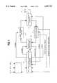
- FIG. 7is a diagram showing message flow in the network
- FIG. 8is a schematic block diagram of a transmitter module of a transceiver according to the invention.
- FIG. 9is a schematic block diagram of a receiver module of the transceiver.
- FIG. 10is a schematic block diagram of a main processor and modem interface module of the transceiver
- FIG. 11is a schematic block diagram showing the main processor together with a dual vocoder interface module of the transceiver;
- FIG. 12is a schematic diagram of a multi-stage switched attenuator of the transceiver.
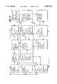
- FIG. 13is a flow chart-type diagram giving an overview of the overall software architecture of the transceiver
- the present inventionhas primary application in wireless data networks, including mobile radio or cellular telephone networks, two-way paging networks, meteor burst PCN data networks and low earth orbiting and geostationary satellite environments, where rapidly and greatly changing connectivity and platform population changes militate against the use of conventional networking techniques.
- the inventionprovides a communication network which makes use of adaptive opportunistic communication between stations in the network.
- the networkis a full mesh network which accommodates rapidly changing connectivity between stations and routes messages dynamically between stations on a co-operative basis to improve data throughput in the network, while minimizing power consumption and interference between stations.
- the inventionoptimises the network capacity by ensuring optimal utilisation of the available spectrum in terms of capacity (Erlangs) for a given area, a given spectrum allocation and a given infrastructure cost (Erlangs/km 2 /Hz/$).
- FIG. 1a single network station is shown schematically in a highly simplified form. It will be appreciated that the network stations may be portable transceivers or fixed stations, or a combination thereof.
- the heart of the stationis a microprocessor-based controller 10 which operates under the control of stored software, which derives information by monitoring transmissions from other stations, both on an ongoing basis and in response to specific probe signals transmitted by the station.
- the stationhas one or more transmitting/receiving antennas 12 which are connected via a combiner unit 14 to an adaptive receiver 16 and an adaptive power amplifier/transmitter 18, all of which are controlled by the controller 10. Data is passed between the controller 10 and the receiver 16 and the transmitter 18 via an adaptive data rate modem 20.
- An input circuit 22receives, for example, voice, data and/or video signals and includes analogue to digital converters with associated adaptive encoding processors, under the control of the controller 10, for converting the signals to a digital format and feeding them to the controller 10.
- the controller 10 of each stationcontinually analyzes data received from other stations which are within range, arising from their communication and interaction from time to time.
- the address information for other stations obtained in this wayis collated and stored, and translated into connectivity information.
- the controllerwaits and monitors the activity of the other stations, seeking an opportunity either to communicate a message, as an originating station, or to relay a message to another station on behalf of a different originating station.
- the controllerdetects a quiet time on the network, it transmits a probe signal which contains its own address and the address of the destination station, inter alia.
- the controllerOn receiving an acknowledgement signal from another station which is able to act as an intermediate or relay station, the controller then transmits a burst of data containing a message (either an original message or a relayed message).
- the transmission power, data rate, message lengths, message priority, message time to live, message retransmission rate and other parametersare controlled according to information derived from the acknowledged signal, relating to the characteristics of the channel or link between the stations at that time.
- the timing of the transmissionis selected to take advantage of peaks in the signal strength or signal-to-noise levels typically experienced in a Rayleigh fading environment, so that the mode of communication is effectively an opportunistic time division multiple access system. By operating in peak mode, the required transmission power is reduced, reducing interference between stations, and reducing the necessity for the retransmission of messages.
- peaksmay be due, for example, to variations in signal path amplitude, frequency or phase variation, noise or interference, multipath effects, etc.
- the occurrence of peakscan be detected by monitoring physical characteristics of received signals or by monitoring bit error rates as a function of time.
- the state diagram of FIG. 3 and the flow diagrams of FIGS. 4a and 4billustrate the operation of each station in the network.
- the state diagram of FIG. 3illustrates the overall operation of a station, while the flow diagrams of FIGS. 4a and 4b illustrate a typical opportunistic message transmission procedure.
- a key feature of the described systemis the continual monitoring by each station of the activity of other stations in the network, both from the point of view of selecting an optimal channel for each transmission, and for selecting a station to which a message is to be transmitted.
- Each message transmitted over the networkwhether it is a data message as illustrated in FIG. 5 or a probe/acknowledge message as illustrated in FIG. 6, contains its originating address, its destination address, and the address of the station relaying the message. Therefore, any other station monitoring the channel will hear which other stations are transmitting information, and which stations are relaying that information.
- the originating and destination addresses in each messageremain the same, but the intermediate address will be the address of the relaying station being used for the next "hop".
- each stationanalyses the information it has derived from the channel and the stations around it and will then opportunistically, via a probe/acknowledge cycle, choose another intermediate station address, to relay the message onwardly via that station.
- an originating station and a destination stationmay be able to communicate directly.
- the originating stationwill not be able to communicate directly with the destination station, but will be able to transmit its message to an intermediate station which it has heard talking to the destination station, either directly or via one or more additional intermediate stations.
- Each time a message is sent to an intermediate station which cannot directly communicate with the destination stationit will seek a further intermediate station that is in communication with the destination station or that it has heard talking to the destination station.
- the intermediate stationcannot reach the destination station through any route (i.e. it has received no information from other stations containing the address of the destination station) it will immediately revert back to the previous station, so that the station can attempt to find another route for transmission of its message.
- probe/acknowledgement messagethere are at least two different message types being transmitted over the network: a probe/acknowledgement message and a data message.
- the probe/acknowledgement messagesare used primarily for control and feedback adaption, while the data messages are used for information/message transmission across the network.
- the data messagecan use any data rate, while the probe/acknowledgement revert back messages normally use a standard network data rate.
- probe/acknowledgement messagescan be sent at different data rates, allowing the stations to establish what rate is best for the particular circumstances.
- a typical opportunistic message send flow modeis illustrated.
- a messageis entered or received for relay.
- the controller 10then goes to block B where it determines the message's priority depending on the elapsed time since the message was entered/received, the priority attributed to other messages in its stack, and the opportunities it has, based upon the historical data developed in block J, to send the message. It then examines the information based upon network statistics and monitoring and establishes its message priority with respect to other message priorities on the network, taking into account network traffic.
- the controllerwill go to block D and wait in monitoring mode for a period of time to hear either the destination station itself, or a relay talking to the destination station. Using this method, a single or double hop route is found.
- the controllerproceeds to block E where it waits for an opportunity to transmit by waiting for a break in network activity and for channel conditions to be suitable, and then enquires or probes for the destination address in block H. If the destination station responds, the controller proceeds to block I where it will, based on adaptive feedback, send a message to the destination station. The controller then returns back to the monitoring mode in block D.
- the controllerwill then probe for an opportunity to transmit via a relay or intermediate station (block G), and based on adaptive feedback from any such relay, send the message via that relay (block F). Depending on the results of the revert back message from that relay, the controller will return to the monitoring mode of block D.
- a stationWhen a station probes, it can also probe for any one of a particular group of stations, or probe for a station that has "heard” a particular station or a station that has “heard” a transmission to a particular station. Thus, probing can be used to locate other stations, or to find opportunities to communicate with other stations.
- the messageWhen the message is successfully transmitted onwards by the relay or intermediate station, it sends a revert back signal, together with further adaptive information, to the originating station.
- the originating stationthen returns to the monitor mode of block D and waits for an end-to-end message acknowledgement, as well as any further requests for relaying messages or receipt of messages.
- the destination stationWhen a message reaches its final destination, the destination station will send back a message acknowledgement which might follow, due to the adaptive opportunistic operation of the network, a completely different route back to the originating station.
- the probe/revert back messages employed by the networkare used by the stations in an interactive manner in an analogous way to human beings communicating by "knocking" to attract each other's attention, “nodding” to indicate successful communication, and other adaptive interaction to modify the various parameters of their communication.
- the stations of the networkare not arranged in a hierarchy with controllers, base stations or parent stations.
- the network hierarchyis fully distributed and only message priority and transmission opportunities dictate message flow.
- the stations of the networkwork co-operatively to maximise the overall throughput of the network.
- One of the objectives of the overall networkis to co-operatively maximize the capacity in terms of Erlangs for a given spectrum allocation, a given area and a given equipment infrastructure investment.
- an objective of the networkit to maximize Erlangs/km 2 /Hz/$.
- the controller of each stationwill reside at either block D or Block H of the state diagram of FIG. 3. In other words, it will either be monitoring or waiting for transmission opportunities in a high activity network, or adaptively enquiring and receiving occasional feedback in a low activity network.
- the only reason for enquiriesis to create message activity or to find a particular destination or relay opportunity.
- stationswill not probe but will rely on hearing other stations communicating with each other, thereby deriving connectivity and routing information.
- normal operationwill usually comprise waiting for a destination station to communicate and then instantaneously and opportunistically sending a message, either to that destination station directly or to an intermediate station talking to the destination station.
- the networkallows any station to enter the network without the need to update network lists or to transfer network information.
- Stationsare able to adapt each other dynamically in a co-operative fashion so as to maximise message throughput and minimize contention between stations.
- Stationsare able to probe and request a channel between them in order to find opportunities of connectivity.
- Stationsare able to use revert back check acknowledgements, thereby dynamically adapting each other's operating parameters and informing other stations as to the status of message flow (e.g. message arrival, requests for retransmission of messages, etc).
- Stationsare able to learn and form knowledge bases which allow them to make an optimal first try at sending a message across the network, based upon monitored information and feedback from other stations.
- a stationhas an "intelligent" stack of network messages. When any particular station is heard, a suitable message can be drawn from the stack dynamically and sent to that particular station, to make maximum use of transmission opportunities. Thus, where a station is routing messages on behalf of a number of different stations through a number of different other stations, it can opportunistically combine messages and forward them to other stations, reducing overhead on the network.
- Each stationcan monitor link or channel quality in terms of signal strength, interference, signal-to-noise ratio, spike noise, etc., in order to find the best opportunity to send messages during periods of relative quietness and optimal signal strength.
- Stationshave the ability to transmit the minimum required power level required to reach the destination station or an intermediate station, thereby minimising interference to other stations.
- the transmission poweris adapted on a transmission by transmission basis, and is increased or decreased based upon information contained in revert back check signals from other stations. Routing and relaying of signals is optimised so as to minimize stations transmitting at high power, thereby minimising interference and power consumption.
- Stationsalways attempt to transmit using channel peaks, based upon availability, using reduced signal strength and further minimising interference with other stations.
- the described communication networkhas a number of advantages compared with prior art systems. For example, if a station finds itself in a high noise environment, it may relay a message to an adjacent station, outside the noise environment, which can then in turn relay the message to the destination station. Alternatively, stations in a highly congested environment can reduce their power levels so as to effectively minimise interference, and relay messages amongst each other at low power and high data rates, thereby effectively using less time on the overall network.
- the networkcan be interfaced transparently to a conventional multi-hop stable routing network with complete transparency. For example, should more than the typical 3 hops be required to transmit a message from the originating station to the destination station, the message can be routed to the fixed network which uses conventional routing. The final 3 hops can again take place in the above described dynamic network.
- the originating station 24originally heard an intermediate station 26 communicating with another station 28, and therefore routes a message which it wishes to transmit to the station 28 via the station 26. If at that moment the connectivity between the stations 26 and 28 is lost, the station 26 may make an opportunistic decision to send the message via, for example, another station 30, which has higher connectivity to the station 28. It will be understood that the alternate routing from the station 26 via the station 30 to the station 28 is independent of the originating station and is an opportunistic decision taken at the station 26. Similarly, if the station 30 finds that it cannot communicate directly with the station 28, it too will opportunistically seek an alternative route, and may have to relay its message via another station 32.
- Each stationhas an artificial intelligence engine, which generates the routing variables and adaptation parameters.
- the parameters gathered from the monitoring engine and the long-term data baseplay the role of the training patterns required for the artificial intelligence.
- the weights of the various parameters within the artificial intelligenceare then adjusted and trained, based upon the dynamic changing parameters of the network.
- the overall networkmay be considered as a greatly parallel-distributed processing system with the ability to configure routes for data flow and to adapt the transmission power and other parameters of each station through dynamic learning. This provides a near optimum flow of data across the network and optimises network capacity.
- the networkmay, alternatively, be considered as a greatly parallel-distributed processing system with the ability to configure parameters such as transmission power, data rate, rate and duration of signal transmissions, through dynamic learning. This allows dynamic responses to traffic conditions and changing propagation conditions measured through out the network.
- the networkcan thus operate to optimise message traffic requirements by adapting one or more parameters of operation.
- the basic network protocolis very simple, requiring only two basic message types and the adaptive feedback ability described above, even very simple artificial intelligence can be used to drive each station in small, low capacity networks.
- the "intelligence" of the stationscan be upgraded without the necessity of upgrading the basic link protocols. Since no routing information is passed around the network, low and high "intelligence" stations can be mixed without compatibility problems.
- the networkSince the network is a co-operative network, the only level of service that can be "guaranteed" to users is that based upon the level of priority and the extent of the network. Where network traffic becomes high and delays increase, additional stations can be added to the network, some being connected to more traditional high capacity networks, thereby maintaining overall message flow. However, the network of the invention will never fail catastrophically, since there is no single point of failure such as a base station or controller node.
- Different usersmay have different levels of priority. For example, some users may have access to higher transmission power or high duty cycles and the ability to introduce messages with a higher priority embedded in them, as well as the ability to re-introduce messages more often, even if end-to-end acknowledgments are not received.
- the described systemallows high priority and low priority users to be mixed in a common network.
- this diagramis used to explain the probability of message flow via the network.
- the messagesare entered and opportunistically wait for any station which has a high probability of routing a message to the destination station O.
- stations closer to the destinationhave a higher probability of communicating with the destination.
- the highest probability of relayis from, say, the originating station A to a station B.
- peaks of opportunityexist between the originating station A and all of the stations B to O in an opportunistic environment, it is possible for the message to be routed directly to the destination station O from the originating station A, but this has a very low probability.
- the messagecan be sent to any of the stations G to O. Assume that the message is transmitted from the station B to a station I, based upon an opportunity. Again, the station I might transmit to any of the stations L to O. Assume that the station I transmits the message to a station M, the highest probability route will then be to the destination station O itself.
- the number of stations with a higher probability of communicating with the final destination stationdecreases, until at the final hop there is only one choice. It is therefore an imperative in the network to make the number of opportunities of intermediate hops as large as possible, and hop to a penultimate relay selected so that the last hop has a very high probability of success.
- a higher probe rate and higher general network activityWill increase the number of opportunities, and therefore the probability of finding an opportunity.
- the size of the hopsmust be reduced or, alternatively, the probe rate or level increased. This emphasises the importance of the "extra" hops that may be necessary to make the last hop one of extremely high probability. Since the system is always looking forward 3 hops, it is possible to ensure that the last hop has a higher probability.
- Equation 1gives the probability of success of a single hop: ##EQU1## where P i is the probability of transmitting to a station with some connectivity to the originating station and higher connectivity to the destination station, and where n is the number of stations.
- the probability of each intermediate hopis a strong function of the number of "choices". Therefore, even if the intermediate hops have a low probability, the probability of finding any one of them is high. Therefore, large hops with low probability can be made for the first hops, providing the last hops have high probability. In this case, the total probability which is a product of all the intermediate hop probabilities, will be high. (See equation 2).
- low power stations with low connectivity between themselvescan route messages on behalf of each other towards destinations, providing there are sufficient of them.
- vehiclescan relay messages between each other and towards fixed dispatch centres which have higher power and duty cycle, and will provide a high probability last hop to the destination vehicle once messages are routed close enough to them from other vehicles.
- messagescan be routed from home to home until the messages are sufficiently close to a data gathering or data dissemination station which has higher power and a higher duty cycle and which can ensure a high probability last hop.
- Individual stationscan "scavenge" messages opportunistically in order to enhance connectivity. For example, if a first station is communicating with a second station, a third station, which has determined that it is better placed to act as a relay between the first station and the desired destination station, or that it can act as a relay between the first and second stations, can actively intervene to act as a relay, thereby allowing the first and second stations to reduce their transmission power levels.
- the prototype of the station which is described belowwas implemented as a portable radio telephone transceiver for use in a voice communication network.
- the prototype transceiveris intended to be used as a vehicle-mounted unit and was constructed in a housing which can be mounted under the dashboard or in the luggage compartment, for example, of a motor vehicle and which is supplied with 12 volt DC power from the vehicle electrical system.
- the transceivercould be provided in a miniaturised battery powered for for use as a personal transceiver, or could be used as a base station or a fixed point relay, for example, mounted on a tower or mast with a suitably efficient antenna.
- FIG. 8shows a transmitter module of the transceiver, comprising an adaptive power amplifier with an output power range from minus 40 dBm to 70 watts, a frequency synthesiser MSK modulator with dual data rates of 8 kilobits per second and 80 kilobits per second, power control circuitry and power protection circuitry.
- FIG. 8also shows power measurement circuitry and a receive/transmit attenuator of the transceiver.
- FIG. 9shows a receiver module of the transceiver, which includes a low noise preamplifier, a mixer, two IF stages and two MSK demodulators operating at 8 and 80 kilobits per second.
- FIG. 10shows the main nicroprocessor of the transceiver together with associated interface and control circuitry
- FIG. 11shows the microprocessor together with a dual vocoder interface and other user interface components.
- an antenna 100is connected a low power sensing circuit 101, a transmit/receive switch 103 and a forward and reflected power measurement circuit 161 to a power amplifier 145.
- the power amplifieris fed by first and second driver amplifiers 142 and 144 from a buffer amplifier 140, which is in turn fed with the output of a voltage controlled oscillator (VCO) 139 which forms part of a modulator/synthesiser circuit.
- VCOvoltage controlled oscillator
- a synthesiser 138runs at the transmit frequency (in the 45 to 50 MHz range) and is two-point frequency modulated, meaning that the frequency reference source 137 for the synthesiser is modulated by the low frequency component in the data to be transmitted, while the VCO 139 is modulated by the high frequency component of the data.
- the modulationis carried out by respective analog switches 135 and 136 controlled by respective driver circuits 133 and 134 which arc fed with data to be transmitted at the relevant data rates at which the transmitter operates.
- the resultis a GMSK signal which is fed to the amplifier section of the transmitter.
- the operating frequency of the synthesiser 138When receiving, the operating frequency of the synthesiser 138 is shifted a short distance away from the receive frequency of the transceiver, a distance just greater than the bandwidth of the widest IF filter in the receiver. This is done by feeding the output of the frequency reference 137, which operates at 10 MHz, into a divider that counts cycles and at the overflow value of the counter removes a cycle going into the synthesiser. This allows rapid shifting of the synthesiser frequency on transmission, without the need for reprogramming of the synthesiser when the transceiver goes into receive mode, and avoids the delays that would be involved in reprogramming or restarting the synthesiser when switching from receive to transmit mode and vice versa.
- the processor circuitry of the transceiverBased on its monitoring of the channel in use, the processor circuitry of the transceiver generates a power control signal via a power control circuit 141 which is applied to a comparator circuit 143 comprising a gain control circuit and a low pass filter.
- the comparator circuit 143compares the power control signal with a transmission power measurement signal, and outputs a control signal which varies the gain of the second driver amplifier 144 to increase or decrease the transmission power accordingly.
- This circuitoperates to adjust the transmission power to correspond to the power of signals received on the same channel, so that transmissions take place at an adequate but not excessive power level.
- the buffer amplifier 140regulates the output level from the modulator VCO 139 to a constant level, while the first and second driver amplifiers 142 and 144 are class B amplifiers, while the gain of the second driver amplifier 144 being controllable.
- the amplifier 145is a class C amplifier, and its current consumption is measured to provide an indication of the output transmission power of the transceiver.
- the comparator circuit 143effectively provides a feedback loop which adjusts the output power of the transceiver towards a setpoint controlled by the power control circuit 141, and varies the output of the power amplifier from 100 mW to 70 W.
- a controllable attenuatoris switched into the output path when output transmission power lower than 100 mW is required.
- the attenuatorcan apply up to 60 dB attenuation in 10 dB steps.
- the overall transmission dynamic rangecan be adjusted over a range of 100 dB.
- the attenuator 102comprises a ladder of resistors 200 which are arranged in three groups 201, 202 and 203, with values calculated to provide an attenuation of 30 dB, 20 dB and 10 dB respectively. (See FIG. 12.)
- the resistorsare switched in and out of circuit by controllable switches 204 comprising PIN diodes which are effectively biased on or off by control signals from the processor circuitry of the transceiver.
- the output transmission power of the transceivercan be varied between -40 dBm and 50 dBm, with rapid switching between power levels. This allows the transmitter circuitry to output consecutive bursts of data at different power levels as required.
- the attenuator circuit 102is also used in input power measurement, since the power measurement circuit 161 can not operate over a very large range, typically only 60 dB. By adjusting the switched attenuator appropriately, the effective measurement range of the power measurement circuit 161 is extended to 120 dB.
- the receiver module of the transceivercomprises a high Q bandpass fitter 104 which is connected to the transmit/receive switch 103.
- the filter 104has a bandwidth of approximately of 1.5 MHz and a low insertion loss.
- the filter 104is followed by a low noise preamplifier 105 with a high dynamic range, the output of which is fed into a mixer 106 which forms part of a 10.7 MHz IF strip.
- the output of the mixeris fed through a bandpass filter 107 to a first high-gain IF amplifier 108.
- the output of this amplifieris fed to first and second ceramic filters 109 and 110 which provide bandpass filtering, centred on 10.7 MHz, of 150 kHz.
- a second IF amplifier 111follows the filters 109 and 110, to compensate for their insertion loss.
- a further ceramic filter 112with the same characteristics as the filters 109 and 110, follows the second IF amplifier 111, to further improve the selectivity of the receiver. This filter also provides a time delay which is required for noise blanking (see below).
- the output of the filter 112is fed to a noise blanker circuit 113 which is essentially a controllable switch controlled by the output of an amplifier 126 which provides a blanking pulse output and which is used to "blank" noise pulses, with attenuation of 40 dB when open.
- the output of the noise blanker circuit 113is fed through a narrow band 15 kHz crystal filter 114 which provides a selectivity of 15 kHz centred on 10.7 MHz.
- the output of this filteris fed into a third IF amplifier 115 which has sufficient gain to overcome the losses of the previous stages and to provide sufficient output levels to drive the NE 615 FM integrated circuit 116 which follows.
- the IF strip of the receiver moduleprovides gain and selectivity in two bandwidths simultaneously, namely 150 kHz and 15 kHz. This allows simultaneous measurement and demodulation within two different bandwidths and at two different data rates.
- the use of parallel demodulation chains with parallel data synchronisation and demodulation of the dataallows simultaneous data to be demodulated from two different stations at two different data rates, with one of the two being chosen, based upon opportunistic decisions.
- the NE 615 FM integrated circuit 116is used to implement a 455 kHz IF strip.
- the deviceincorporates a mixer/oscillator, two limiting intermediate frequency amplifiers, a quadrature detector, a muting circuit, a logarithmic received strength indicator (RSSI), and a voltage regulator.
- RSSIlogarithmic received strength indicator
- the output from the third IF amplifier 115is converted in the integrated circuit 116 to a 455 kHz signal which is fed through a ceramic filter 117 having a bandwidth of approximately 15 kHz centred on 455 kHz, and then amplified to provide an RSSI output signal.
- This amplified signalis passed through a second ceramic filter 117, providing further selectivity, and amplified again, providing an overall gain of 90 dB.
- the range of measurementis extended by 60 dB through the use of the switched attenuator circuit 102 (described above) to provide a total measurement range of 160 dB.
- the integrated circuit 116includes a Gilbert Cell quadrature detector which operates in conjunction with a quadrature phase shifter 118 to provide FM demodulation of the incoming minimum shift key (MSK) data.
- This data waveformis taken from the output of the quadrature detector through a filter and is available as narrow band output data (8 kbps).
- the use of a quadrature detectorprovides a rugged and effective method of demodulation which is immune to frequency offsets and phase distortion and does not require carrier recovery time.
- a wide band IF stripis fed from the output of the first 150 kHz ceramic filter 109 and comprises a gain stage 119, the output of which is fed into an FM IF integrated circuit 120 comprising an NE 604 chip.
- This deviceis a low power FM IF system incorporating two limiting, intermediate frequency amplifiers, a quadrature detector, a multi circuit a logarithmic received strength indicator and a voltage regulator.
- the integrated circuit 120uses a 150 kHz ceramic filter 121 to provide a wider bandwidth RSSI output signal, so that the receiver module can make high dynamic range signal strength measurements simultaneously in a 15 kHz and a 150 kHz bandwidth.
- a quadrature phase shifter network 122is provided to allow the integrated circuit 120 to demodulate MSK data in a similar manner to the integrated circuit 116.
- the integrated circuit 120is also used for noise blanking of narrow band received data. This is done by detecting short noise spikes which are common in low VHF bands and are significantly shorter than the data period. For example, in the 455 kHz IF circuit (block 116) data is detected at 8 kbps, corresponding to a bit period of 125 microseconds. If a noise spike of, say, 12 microseconds occurs, this will inject noise for only 10% of the bit period. If the noise spike is passed through the 15 kHz filter, the pulse duration will become approximately 60 microseconds, resulting in significant distortion of a single data bit. The noise blanker therefore attenuates such noise pulses before they enter the narrow band filters of the 455 kHz IF stage.
- the pulse durationwill be approximately 6 microseconds, and if it is removed before the 455 kHz IF strip, it will have a negligible effect on the bit error rate of the 8 kbps data.
- a differential trigger 123 and a timer 125generate short pulses corresponding to the duration of the noise pulse once the latter has passed through the various filters. Since the noise pulses are typically only nanoseconds long, the duration of the pulses at the output of the filters will be set to approximately 10 microseconds and the timer 125 is therefore set to generate 10 microsecond blanking pulses. This delay corresponds to approximately 10% of the period of a single data bit.
- a spike counter and level detection circuit 124is provided to allow the detection and counting of noise spikes, which information can be used as an adaptive feedback parameter to select the duration of data transmissions, and the data repeat rate, etc. For example, if noise spikes are measured at a 100 Hz rate, the wide band data could be transmitted in bursts between noise spikes at 10 ms intervals, thereby achieving a significant improvement in performance.
- the noise spike detection signal from the counter circuit 124can be used together with bit error performance data and RSSI information to provide a number of adaptive feedback parameters for use in the operation of the transceiver.
- a receive synthesiser 160provides a local oscillator at 55.7 MHz to 60.7 MHz, mixing down from the 45 MHz to 50 MHz RF frequency to the 10.7 MHz IF.
- This synthesiseris required to hop in frequency, based upon instructions from the main processor, independently of the transmit synthesiser 138.
- the synthesisercan be programmed to hop in frequency steps which correspond to channels having a bandwidth which is the same as that of the narrow band data. Since the narrow band data is within a 25 kHz channel, the synthesiser may be programmed to hop to any channel within the bandwidth 45 to 50 MHz in 25 kHz steps. This allows the receiver to demodulate, within milliseconds, data on different receive channels between 45 and 50 MHz.
- the described transmitter/receiver moduleslend themselves to frequency hopping operation, with the transmission and reception channels being hopped together or independently. It will be appreciated that other transmission schemes, such as direct sequence spread spectrum (DSSS) operation, might be preferable in particular applications.
- DSSSdirect sequence spread spectrum
- each stationtransmits probe signals and monitors received signals, it switches from one frequency channel to another, recording information as to which other stations are available on the various channels and noting their identity, signal strength, frequency of transmission and duration of transmission. Apart from switching between transmission and reception frequencies, each station can also (where applicable) select between different antennas which are optimised for different frequencies or transmission directions, for example.
- a group of stationsmay hop synchronously or semi-synchronously.
- a group of stations relaying messages on behalf of one anothermay switch frequencies/channels as a group.
- the operation of the network in the above described frequency adaptive mannercan be considered as a form of slow frequency hopping, frequency scanning, frequency division multiple access methodology.
- the transmission/reception frequencyis one of the adaptation parameters of the apparatus of the invention, it can be changed as required using probe and revert back signals. For example, one station may request another station to move to another frequency to "meet" it there, to provide an opportune relay link, or to reduce traffic on another channel.
- Adjustment of the transmission/reception frequencymay also be employed in the case of high priority data, where a free channel can be cleared and high power, the data rate transmissions used directly between two stations, for example.
- Certain frequenciesmay be used as congregation or meeting frequencies with multiple hop, fall connectivity, where stations exchange small amounts of information at lower power levels and high data rates, thereby minimising their on-air time and maximising the overall network connectivity and information exchange.
- stationsmay elect, by coordinating between themselves (and possibly one or more intermediate relay stations) to change to an opportunistically selected channel, which has low noise, low interference and/or low traffic for both the source, the destination and the relay stations.
- This type of opportunistic frequency changewill most often occur when it is necessary to exchange large volumes of data, normally requiring increased power levels to improve connectivity. If the stations are unable to connect with one another at a first chosen frequency, they can choose another channel or return to the original calling channel to re-establish connectivity.
- the frequency used between stationsis adapted in the same manner as other parameters such as the transmission power, the data rate, or the timing of a transmission to match a channel peak.
- Opportunistic channel hoppingcan be used to find quiet channels with low interference or noise, or to find a channel with traffic on it in order to locate a particular relay or destination station. Therefore, in quiet networks the stations may tend to congregate on a single channel, making efficient use of that channel through adaptive power and adaptive data rate transmissions.
- stationscan opportunistically hop off the channel to adjacent channels to exchange large volumes of data or to form subgroups. Individual stations seeking transmission opportunities can hop between groups of stations operating on different channels, and in certain circumstances stations may hop together as a group from channel to channel for the purpose of creating transmission opportunities.
- channel hoppingcreates transmission opportunities with different characteristics which, in conjunction with other time varying channel characterstics, effectively adds an additional variable into the opportunistic environment used by the network.
- the effect of the above described opportunistic frequency hopping operation of the networkis that stations operating as intermediate or relay stations may receive a message from a particular station on one channel, and hop to a second channel to pass the message on efficiently.
- an originating stationmay not know on which channel to find the destination station, but through the probing process, a relay station opportunistically takes the message from the originating station and transmits it to the destination station, which it has recently heard on another channel.
- Establishing the channels which stations are usingis therefore a distributed function, with numerous stations scanning continually and assisting one another in finding which channels other stations are on. If a station cannot find the destination station, and has probed on a number of different channels, the message is passed on, allowing other stations to probe for the destination station on various channels.
- the overall receiverallows simultaneous demodulation, synchronisation and capture of data at two different data rates with a high range of dynamic signal differences.
- the described embodimentcaters for two different data rates, it is possible to extend the concept to cater for further parallel data rates, typically spaced by orders of magnitude.
- the highest data rateshould be chosen, based upon the spectrum allocation, to fill the complete spectrum allocation. Therefore stations can call each other opportunistically and dynamically at any data rate, and all other stations can monitor and demodulate the transmissions. Due to the isolation between the different data rates, in many circumstances a station will be able to demodulate the transmissions of two different stations simultaneously, one at a higher rate and one at a lower rate.
- the main microprocessor 149is a type 386 EX chip with associated static and dynamic RAM 150 as well as several EEPROM's (not shown) which program the operation of the receive, transmit, interface and processing functions of the transceiver.
- the processor 149has an associated real time clock 148.
- the processorcommunicates with a main analog to digital converter 146, a main peripheral interface 147, and a high speed serial controller chip 131, which in the prototype transceiver was a Zilog Universal Serial Synchronous controller chip.
- Data to be received and transmittedis fed via the serial controller 131 to respective encoder/decoders 128 and 130 and their respective GMSK modems 127 and 129, operating at 8 kbps and 80 kbps.
- the modemswere type FX 589 GMSK modems.
- Output datais fed from the modems 127 and 129 to a transmitter interface 206 controlled by the peripheral interface 147 and a power control circuit 132.
- the modemsinclude a lock input which is controlled by the processor, allowing the modems to search for and acquire signals quickly and then to be locked on, thereby reducing noise and interference, in particular interference resulting from other stations. This lock feature allows the modems to pick out stations under processor control, which is important to the operation of the invention.
- Incoming data from the receiveris fed via a receiver interface 207 to the modems 127 and 129 and via the encoder/decoders 128 and 130 to the serial controller 131 for processing by the main processor 149.
- the broad and narrow band RSSI signals and the spike counter level signals from the receiver moduleare fed via the interface 207 to the analog to digital converter 146 for processing by the processor 149.
- the vocoder interface module of the transceivercomprises dual vocoders 152 and 153 which are utilised, in the described embodiment, to convert voice signals to data for transmission between stations in a network.
- the vocoder interface moduleessentially converts speech into a digitised form, and then compresses and "packetises" it before passing it to the processor circuitry.
- the vocoders used in the prototype transceiverwere Qualcomm type Q4400 vocoders.
- audio signals from a microphone 208are fed via a microphone amplifier 158 to first and second PCM modules 155 and 156 which sample the audio data and convert it to a PCM format.
- the PCM datais fed to the data input of each vocoder and internally grouped together into 20 millisecond frames (160 PCM samples per 20 millisecond frame). These frames are encoded into packets and output to the main processor 149 every 20 milliseconds.
- Each packet of compressed speech datais transferred to the processor in a TX frame response packet, which contains the data rate for the frame as well as the valid data bits.
- the processordetermines the maximum and minimum data rate limits for the next 20 millisecond frame to be processed.
- Each packet of compressed data received by the processor 149is formatted for transmission, with a processing delay between arrival of the first PCM sample in the 20 millisecond frame and the completion of the encoding process for that particular frame being approximately 47.5 milliseconds.
- the processorreads the data rate bit and strips out redundant information before packetising the data and outputting it via the serial controller chip 131.
- the main processor 149can instruct the vocoders to operate fixed rates of, say, 4000 and 9600 bps, and select data from either vocoder according to a calculated opportunity.
- the processorwould have a choice of two different data packet sizes for transmission at each available transmission opportunity.
- the vocoderscan be set with different vox settings and different coding delays.
- the processorcould, for example, set one of the vocoders with a low vox setting and a low data rate, with the other being set at a high vox setting and a high data rate.
- This schemecan be used to ensure that the beginning of a speech transmission is captured, with a switch subsequently being made to a high data rate, high quality transmission.
- the provision of dual vocodersalso allows one vocoder to be used to demodulate data while the other modulates data, therefore avoiding delays in interactive speech, with one vocoder being opportunistically switched over to pick up the beginning of a reply while the other is still playing out the end of the received speech. This arrangement significantly reduces delays, particularly in an interactive situation.
- Received datais sent to one of the vocoders 152 and 153, while the other receives blanked or erased data frames. Blanked frames are also output when corrupted data is received, to prevent a distorted output from the vocoder. In these circumstances, the vocoders interpolate or reconstruct the missing data.
- the received output from the vocoder 152 or 153is fed to the respective PCM module 155 or 156, with the audio output from the relevant module being selected by an analog audio switch 157.
- the selected audio outputis fed via a speaker amplifier 159 to a loudspeaker 210.
- the overall adaptive rates of the vocodersare adaptively changed within broad boundaries due to long term feedback over seconds, and opportunistically changed within tens of milliseconds, based on selection of the buffered data frames for a number of parallel vocoders.
- the speechis replayed continuously on all the vocoders at a destination station, and using simple analog selection, the voice output is selected from one of the vocoders. Timing is maintained between the parallel vocoder paths by the insertion of blanking and erasure commands to those vocoders which have not received data packets.
- the voice activated switch function of the vocodersis used to distinguish when a user is speaking.
- the decoder functionwill normally have priority over the encoder function. If both users at opposite ends of a link are speaking at the same time, the user at the far end will normally be given priority.
- So-called "comfort" noise frames and the above described blanking and erase commandsare used to fill in gaps due to packets which are lost in transmission, or packets which have been delayed and are received out of sequence due to a multi-hop link.
- the received speechcan efficiently be speeded up by removing comfort noise frames and slowed down through the insertion of blanking frames, allowing for a smooth flow of speech, despite the variable delay over the link.
- each packet transmittedto be given a relative time stamp, which is decremented as the packet is passed through the network at a rate which is set relative to the real time. Packets which are not successfully received by the intended destination station within a predetermined time-out period are deleted, preventing clogging of the network.
- Each stationmaintains a log of all the messages passing through it, to prevent messages travelling in a closed loop in the network. Once a station has passed a particular message on, it will in future, by revert back checks, prevent that message from passing through it a second time, and will simply redirect it elsewhere. Together with the above described time-out marking, this prevents messages from circling around uselessly in the network.
- FIG. 13is a schematic diagram showing the overall software architecture of the transceiver, in a flow diagram form. The diagram summarises the above described operation of a transceiver operating in a network of similar transceivers.
Landscapes
- Engineering & Computer Science (AREA)
- Computer Networks & Wireless Communication (AREA)
- Signal Processing (AREA)
- Databases & Information Systems (AREA)
- Mobile Radio Communication Systems (AREA)
- Radio Relay Systems (AREA)
- Data Exchanges In Wide-Area Networks (AREA)
- Small-Scale Networks (AREA)
Abstract
Description
P.sub.TOT =P.sub.HOP1 ×P.sub.HOP2 ×P.sub.HOP3 (2)
Claims (16)
Priority Applications (1)
| Application Number | Priority Date | Filing Date | Title |
|---|---|---|---|
| US09/570,892US6965568B1 (en) | 1994-12-19 | 2000-05-15 | Multi-hop packet radio networks |
Applications Claiming Priority (3)
| Application Number | Priority Date | Filing Date | Title |
|---|---|---|---|
| ZA9410066 | 1994-12-19 | ||
| ZA94/10066 | 1994-12-19 | ||
| PCT/GB1995/002972WO1996019887A1 (en) | 1994-12-19 | 1995-12-19 | Multi-hop packet radio networks |
Publications (1)
| Publication Number | Publication Date |
|---|---|
| US6097703Atrue US6097703A (en) | 2000-08-01 |
Family
ID=25584680
Family Applications (2)
| Application Number | Title | Priority Date | Filing Date |
|---|---|---|---|
| US08/849,875Expired - LifetimeUS6097703A (en) | 1994-12-19 | 1995-12-19 | Multi-hop packet radio networks |
| US09/570,892Expired - Fee RelatedUS6965568B1 (en) | 1994-12-19 | 2000-05-15 | Multi-hop packet radio networks |
Family Applications After (1)
| Application Number | Title | Priority Date | Filing Date |
|---|---|---|---|
| US09/570,892Expired - Fee RelatedUS6965568B1 (en) | 1994-12-19 | 2000-05-15 | Multi-hop packet radio networks |
Country Status (21)
| Country | Link |
|---|---|
| US (2) | US6097703A (en) |
| EP (1) | EP0811286B1 (en) |
| JP (1) | JP3527957B2 (en) |
| KR (1) | KR100390140B1 (en) |
| CN (1) | CN1134941C (en) |
| AP (1) | AP621A (en) |
| AT (1) | ATE207680T1 (en) |
| AU (1) | AU700811B2 (en) |
| BR (1) | BR9510251A (en) |
| CA (1) | CA2208041C (en) |
| DE (1) | DE69523478T2 (en) |
| DK (1) | DK0811286T3 (en) |
| ES (1) | ES2165438T3 (en) |
| MY (1) | MY123040A (en) |
| NO (1) | NO322741B1 (en) |
| NZ (1) | NZ297514A (en) |
| PT (1) | PT811286E (en) |
| RU (2) | RU2157591C2 (en) |
| UA (1) | UA45997C2 (en) |
| WO (1) | WO1996019887A1 (en) |
| ZA (1) | ZA9510789B (en) |
Cited By (146)
| Publication number | Priority date | Publication date | Assignee | Title |
|---|---|---|---|---|
| US20010014092A1 (en)* | 1999-12-27 | 2001-08-16 | Ntt Docomo, Inc. | Packet communication method, node apparatus and packet communication system |
| US20020051425A1 (en)* | 2000-10-27 | 2002-05-02 | Peter Larsson | Method for forwarding in multihop networks |
| WO2002043288A1 (en)* | 2000-11-21 | 2002-05-30 | Starcom Wireless, Inc. | Meteor burst communication system having the capability of simultaneous communication with multiple remote units |
| WO2002047335A1 (en)* | 2000-12-06 | 2002-06-13 | Linex Technologies, Inc. | Distributed network, spread-spectrum system |
| US20020085503A1 (en)* | 1997-08-27 | 2002-07-04 | Philips Electronics North America Corporation | Apparatus and method for peer-to-peer link monitoring of a wireless network with centralized control |
| US20020094799A1 (en)* | 2000-01-31 | 2002-07-18 | Elliott Karl E. | Wireless communication enabled meter and network |
| US20020142732A1 (en)* | 2001-03-28 | 2002-10-03 | Hitachi Kokusai Electric Inc. | Transceiver capable of adaptively selecting a modulation method based on the transmission power and channel condition |
| WO2002078369A1 (en)* | 2001-03-26 | 2002-10-03 | Tropos Networks | Method and system to provide increased data throughput in a wireless multi-hop network |
| WO2002080471A1 (en)* | 2001-03-29 | 2002-10-10 | Nokia Corporation | Method and apparatus of prioritising the usage of slotted links by single network devices in a wireless network |
| US20020167965A1 (en)* | 2001-01-18 | 2002-11-14 | James Beasley | Link context mobility method and system for providing such mobility, such as a system employing short range frequency hopping spread spectrum wireless protocols |
| US20020177460A1 (en)* | 2001-05-02 | 2002-11-28 | James Beasley | Wireless base station to base station synchronization in a communication system, such as a system employing a short range frequency hopping or time division duplex scheme |
| US20020187749A1 (en)* | 2001-05-02 | 2002-12-12 | James Beasley | Wireless base station to base station synchronization in a communication system, such as a system employing a short-range frequency hopping or time division duplex scheme |
| US20020191573A1 (en)* | 2001-06-14 | 2002-12-19 | Whitehill Eric A. | Embedded routing algorithms under the internet protocol routing layer of a software architecture protocol stack in a mobile Ad-Hoc network |
| US20030007453A1 (en)* | 2001-07-06 | 2003-01-09 | Ogier Richard G. | Scheduling mechanisms for use in mobile ad hoc wireless networks for achieving a differentiated services per-hop behavior |
| US20030027577A1 (en)* | 2001-08-06 | 2003-02-06 | Metric Systems, Inc. | Wireless communication system control apparatus and method |
| US6556582B1 (en)* | 2000-05-15 | 2003-04-29 | Bbnt Solutions Llc | Systems and methods for collision avoidance in mobile multi-hop packet radio networks |
| US20030097440A1 (en)* | 2001-11-16 | 2003-05-22 | Alcatel | Adaptive data acquisition for a network or services management system |
| US20030120809A1 (en)* | 2001-12-20 | 2003-06-26 | Bellur Barghav R. | Interference mitigation and adaptive routing in wireless ad-hoc packet-switched networks |
| US20030125067A1 (en)* | 2001-12-28 | 2003-07-03 | Ntt Docomo, Inc | Radio communication system, base station, relay station,mobile staion, and packet transmission control method |
| US20030142658A1 (en)* | 2002-01-31 | 2003-07-31 | Ntt Docomo, Inc. | Base station, control device, communication system and communication method |
| US20030147415A1 (en)* | 2002-02-01 | 2003-08-07 | Renaud Dore | Method for radio link adaptation in a network with contention-based medium access |
| US20030147423A1 (en)* | 2002-02-01 | 2003-08-07 | Ludovic Jeanne | Method for evaluating radio links in a communication network |
| EP1335545A1 (en)* | 2002-02-01 | 2003-08-13 | Thomson Licensing S.A. | Method for radio link adaptation in a network with contention-based medium access |
| EP1335546A1 (en)* | 2002-02-01 | 2003-08-13 | Thomson Licensing S.A. | Method for evaluating radio links in a communication network |
| US20030154254A1 (en)* | 2002-02-14 | 2003-08-14 | Nikhil Awasthi | Assisted messaging for corporate email systems |
| US6678257B1 (en)* | 2000-09-25 | 2004-01-13 | Qualcomm, Incorporated | Methods and apparatus for allocation of power to base station channels |
| US6683886B1 (en) | 1999-10-19 | 2004-01-27 | Koninklijke Philips Electronics N.V. | Bluetooth communication units, wireless communication systems, wireless communication devices, bluetooth communications methods, and wireless communication methods |
| US20040028002A1 (en)* | 2002-07-03 | 2004-02-12 | Hughes Electronics | Satellite communication system utilizing low density parity check codes |
| US20040042434A1 (en)* | 2002-09-04 | 2004-03-04 | Harris Corporation | Intelligent communication node object beacon framework including neighbor discovery in a mobile ad hoc network |
| US6704301B2 (en) | 2000-12-29 | 2004-03-09 | Tropos Networks, Inc. | Method and apparatus to provide a routing protocol for wireless devices |
| EP1189395A3 (en)* | 2000-09-13 | 2004-03-17 | Harris Corporation | A system and method prioritizing message packets for transmission |
| US20040054960A1 (en)* | 2002-07-03 | 2004-03-18 | Mustafa Eroz | Method and system for providing low density parity check (LDPC) encoding |
| US6735448B1 (en)* | 2000-11-07 | 2004-05-11 | Hrl Laboratories, Llc | Power management for throughput enhancement in wireless ad-hoc networks |
| US20040106408A1 (en)* | 2001-05-02 | 2004-06-03 | James Beasley | Wireless base station neighbor discovery in a communication system, such as a system employing a short-range frequency hopping scheme |
| US20040136396A1 (en)* | 2002-10-21 | 2004-07-15 | Yonge Lawrence W. | Contention-free access intervals on a CSMA network |
| US20040166853A1 (en)* | 2003-02-21 | 2004-08-26 | Ntt Docomo, Inc. | Multi-hop communication system, radio control station, radio station and multi-hop communication method |
| US20040174900A1 (en)* | 2003-03-06 | 2004-09-09 | Incucomm, Inc. A Delaware Corporation | Method and system for providing broadband multimedia services |
| WO2004077746A1 (en)* | 2003-02-25 | 2004-09-10 | Koninklijke Philips Electronics N.V. | Interference-based routing in a wireless network |
| US20040205105A1 (en)* | 2003-04-11 | 2004-10-14 | Telefonaktiebolaget Lm Ericsson | Contention-based forwarding with integrated multi-user detection capability |
| WO2004091155A1 (en)* | 2003-04-11 | 2004-10-21 | Telefonaktiebolaget Lm Ericsson | Multi-user diversity forwarding |
| US6826152B1 (en) | 2000-09-13 | 2004-11-30 | Harris Corporation | System and method of conserving bandwidth in the transmission of message packets |
| US20040264379A1 (en)* | 2000-12-29 | 2004-12-30 | Devabhaktuni Srikrishna | Multi-channel mesh network |
| US20050003815A1 (en)* | 2003-04-17 | 2005-01-06 | Karlheinz Schreyer | Procedure for registering a new subscriber in a radio system of an alarm system |
| US6856599B1 (en) | 2000-09-13 | 2005-02-15 | Harris Corporation | System and method of reducing retransmission of messages in a TCP/IP environment |
| US6859463B1 (en)* | 1999-11-08 | 2005-02-22 | Itt Manufacturing Enterprises, Inc. | Methods and apparatus for organizing selection of operational parameters in a communication system |
| US20050041613A1 (en)* | 2001-09-10 | 2005-02-24 | Carmen Kuhl | Method of transmitting time-critical scheduling information between single network devices in a wireless network using slotted point-to-point links |
| US20050063484A1 (en)* | 2002-07-26 | 2005-03-24 | Mustafa Eroz | Satellite communincation system utilizing low density parity check codes |
| US20050114749A1 (en)* | 2003-11-20 | 2005-05-26 | Yonge Lawrence W.Iii | Using error checking bits to communicate an address or other bits |
| US20050135242A1 (en)* | 2003-12-19 | 2005-06-23 | Larsen James D. | Data transport protocol for a multi-station network |
| US20050135270A1 (en)* | 2003-12-19 | 2005-06-23 | Larsen James D. | Probing method for a multi-station network |
| US20050159111A1 (en)* | 2004-01-06 | 2005-07-21 | Samsung Electronics Co., Ltd. | System and method for determining data transmission path in communication system consisting of nodes |
| US20050185621A1 (en)* | 2004-02-19 | 2005-08-25 | Raghupathy Sivakumar | Systems and methods for parallel communication |
| US20050226189A1 (en)* | 2002-06-19 | 2005-10-13 | Christophe Janneteau | Data flow between a communication node and a mobile node in a mobile network |
| US20050246607A1 (en)* | 1998-07-10 | 2005-11-03 | Moulsley Timothy J | Coding device and communication system using the same |
| US6965998B1 (en)* | 1999-12-10 | 2005-11-15 | International Business Machines Corporation | Time stamping method using time-based signature key |
| US20050254449A1 (en)* | 2002-08-13 | 2005-11-17 | Rudiger Halfmann | Method for allocating radio communication resources in a self-organising radio communications system |
| US6987770B1 (en)* | 2000-08-04 | 2006-01-17 | Intellon Corporation | Frame forwarding in an adaptive network |
| US20060012463A1 (en)* | 2004-07-15 | 2006-01-19 | Richard Sharpe | Local 2-way paging systems and associated methods |
| US20060049271A1 (en)* | 2004-09-07 | 2006-03-09 | Hitt Dale K | Wireless sprinkler control |
| US20060114881A1 (en)* | 2000-12-29 | 2006-06-01 | Tropos Networks, Inc. | Mesh network that includes fixed and mobile access nodes |
| US20060171402A1 (en)* | 2003-03-06 | 2006-08-03 | Moore John A | Method and system for providing broadband multimedia services |
| US7114388B1 (en) | 2003-04-21 | 2006-10-03 | Ada Technologies, Inc. | Geographically distributed environmental sensor system |
| US20070097899A1 (en)* | 2003-12-22 | 2007-05-03 | Peter Larsson | Method and system of radio communications of traffic with different characteristics |
| US20070097905A1 (en)* | 2005-10-28 | 2007-05-03 | Samsung Electronics Co., Ltd. | Method for transmitting and receiving data in a multi-hop wireless mobile communication system |
| US20070138272A1 (en)* | 2005-12-16 | 2007-06-21 | Saperstein Jan R | System and apparatus for locating lost items |
| US20070168834A1 (en)* | 2002-07-03 | 2007-07-19 | Mustafa Eroz | Method and system for routing in low density parity check (LDPC) decoders |
| US7263063B2 (en) | 2001-07-06 | 2007-08-28 | Sri International | Per hop behavior for differentiated services in mobile ad hoc wireless networks |
| US20070209059A1 (en)* | 2006-03-03 | 2007-09-06 | Moore John A | Communication system employing a control layer architecture |
| WO2007104920A1 (en)* | 2006-03-16 | 2007-09-20 | British Telecommunications Public Limited Company | Method op relayed wireless transmission |
| US20070223451A1 (en)* | 2006-03-21 | 2007-09-27 | Tropos Networks, Inc. | Mobile access node routing selections through a mesh network |
| US20070263572A1 (en)* | 2006-05-11 | 2007-11-15 | Tropos Networks, Inc. | Mobile node data transmission rate selection |
| US7352770B1 (en) | 2000-08-04 | 2008-04-01 | Intellon Corporation | Media access control protocol with priority and contention-free intervals |
| US20080082895A1 (en)* | 2002-07-26 | 2008-04-03 | The Directv Group, Inc. | Method and system for generating low density parity check codes |
| US20080132185A1 (en)* | 2002-01-02 | 2008-06-05 | Elliott Karl E | Wireless communication enabled meter and network |
| US7398455B2 (en) | 2002-07-03 | 2008-07-08 | The Directv Group, Inc. | Method and system for decoding low density parity check (LDPC) codes |
| US20080205360A1 (en)* | 2007-02-27 | 2008-08-28 | Tropos Networks, Inc. | Balancing clusters of a wireless mesh network |
| US20080261605A1 (en)* | 2005-11-28 | 2008-10-23 | Iwics Inc. | Intelligent Video, Data Streaming and Access to Distributed Resources in a Wireless Network |
| US20080280625A1 (en)* | 2005-09-13 | 2008-11-13 | James David Larsen | Position Determination of Mobile Stations in a Wireless Network |
| US7469297B1 (en) | 2000-08-04 | 2008-12-23 | Intellon Corporation | Mechanism for using a quasi-addressed response to bind to a message requesting the response |
| US20090007706A1 (en)* | 2002-10-28 | 2009-01-08 | Hitt Dale K | Wireless Sensor Probe |
| US20090031228A1 (en)* | 2007-07-24 | 2009-01-29 | Francois Buchs | Method and apparatus for general virtual application enabling of websites |
| US20090040985A1 (en)* | 2005-08-26 | 2009-02-12 | University Of Bradford | Method and apparatus for supporting ad-hoc networking over umts protocol |
| US7590693B1 (en) | 2003-07-17 | 2009-09-15 | Avaya Inc. | Method and apparatus for restriction of message distribution for security |
| US7636370B2 (en) | 2005-03-03 | 2009-12-22 | Intellon Corporation | Reserving time periods for communication on power line networks |
| US20100017608A1 (en)* | 2006-12-14 | 2010-01-21 | Iwics, Inc | Distributed Network Management Hierarchy in a Multi-Station Communication Network |
| US7660327B2 (en) | 2004-02-03 | 2010-02-09 | Atheros Communications, Inc. | Temporary priority promotion for network communications in which access to a shared medium depends on a priority level |
| US20100034134A1 (en)* | 2006-12-14 | 2010-02-11 | Iwics, Inc | Adaptive Antenna System for Diversity and Interference Avoidance in a Multi-Station Network |
| US20100113077A1 (en)* | 2008-10-31 | 2010-05-06 | Samsung Electronics Co. Ltd. | Apparatus and method for uplink power control in wireless communication system |
| US7715425B2 (en) | 2004-02-26 | 2010-05-11 | Atheros Communications, Inc. | Channel adaptation synchronized to periodically varying channel |
| US20100202422A1 (en)* | 2005-12-28 | 2010-08-12 | Panasonic Corporation | Method for selective distribution of communications infrastructure |
| US20100215131A1 (en)* | 2009-02-24 | 2010-08-26 | Ulrich Grosskinsky | Circuit, use, and method for controlling a receiver circuit |
| US7822059B2 (en) | 2005-07-27 | 2010-10-26 | Atheros Communications, Inc. | Managing contention-free time allocations in a network |
| US7826466B2 (en) | 2002-06-26 | 2010-11-02 | Atheros Communications, Inc. | Communication buffer scheme optimized for VoIP, QoS and data networking over a power line |
| US20110069685A1 (en)* | 2009-09-23 | 2011-03-24 | At&T Intellectual Property I, L.P. | Signaling-less dynamic call setup and teardown by utilizing observed session state information |
| US20110142025A1 (en)* | 2000-06-13 | 2011-06-16 | Cpu Consultants, Inc. | Apparatus for generating at least one signal based on at least one aspect of at least two received signals |
| US8000314B2 (en) | 1996-12-06 | 2011-08-16 | Ipco, Llc | Wireless network system and method for providing same |
| US8013732B2 (en) | 1998-06-22 | 2011-09-06 | Sipco, Llc | Systems and methods for monitoring and controlling remote devices |
| US8031650B2 (en) | 2004-03-03 | 2011-10-04 | Sipco, Llc | System and method for monitoring remote devices with a dual-mode wireless communication protocol |
| US8064412B2 (en) | 1998-06-22 | 2011-11-22 | Sipco, Llc | Systems and methods for monitoring conditions |
| US8090857B2 (en) | 2003-11-24 | 2012-01-03 | Qualcomm Atheros, Inc. | Medium access control layer that encapsulates data from a plurality of received data units into a plurality of independently transmittable blocks |
| US8138934B2 (en) | 2007-11-25 | 2012-03-20 | Trilliant Networks, Inc. | System and method for false alert filtering of event messages within a network |
| US8144596B2 (en) | 2007-11-25 | 2012-03-27 | Trilliant Networks, Inc. | Communication and message route optimization and messaging in a mesh network |
| US8149703B2 (en) | 2002-06-26 | 2012-04-03 | Qualcomm Atheros, Inc. | Powerline network bridging congestion control |
| US8171136B2 (en) | 2001-10-30 | 2012-05-01 | Sipco, Llc | System and method for transmitting pollution information over an integrated wireless network |
| US8171364B2 (en) | 2007-11-25 | 2012-05-01 | Trilliant Networks, Inc. | System and method for power outage and restoration notification in an advanced metering infrastructure network |
| US20120106362A1 (en)* | 2005-05-12 | 2012-05-03 | Koninklijke Philips Electronics N.V. | Distributed learning method for wireless mesh networks |
| US8175190B2 (en) | 2005-07-27 | 2012-05-08 | Qualcomm Atheros, Inc. | Managing spectra of modulated signals in a communication network |
| US8275313B1 (en) | 2007-01-15 | 2012-09-25 | Advanced Distributed Sensor Systems | Long range, low power, mesh networking without concurrent timing |
| US8289182B2 (en) | 2008-11-21 | 2012-10-16 | Trilliant Networks, Inc. | Methods and systems for virtual energy management display |
| US20120264471A1 (en)* | 2002-12-10 | 2012-10-18 | Investors Life Insurance Corporation | Techniques for generating and using a reservation map |
| US8319658B2 (en) | 2009-03-11 | 2012-11-27 | Trilliant Networks, Inc. | Process, device and system for mapping transformers to meters and locating non-technical line losses |
| US8332055B2 (en) | 2007-11-25 | 2012-12-11 | Trilliant Networks, Inc. | Energy use control system and method |
| US8334787B2 (en) | 2007-10-25 | 2012-12-18 | Trilliant Networks, Inc. | Gas meter having ultra-sensitive magnetic material retrofitted onto meter dial and method for performing meter retrofit |
| US8410931B2 (en) | 1998-06-22 | 2013-04-02 | Sipco, Llc | Mobile inventory unit monitoring systems and methods |
| US8446884B2 (en) | 2004-03-03 | 2013-05-21 | Sipco, Llc | Dual-mode communication devices, methods and systems |
| US8489063B2 (en) | 2001-10-24 | 2013-07-16 | Sipco, Llc | Systems and methods for providing emergency messages to a mobile device |
| US8493995B2 (en) | 2007-05-10 | 2013-07-23 | Qualcomm Incorporated | Managing distributed access to a shared medium |
| US8502640B2 (en) | 2007-11-25 | 2013-08-06 | Trilliant Networks, Inc. | System and method for transmitting and receiving information on a neighborhood area network |
| US8660013B2 (en) | 2010-04-12 | 2014-02-25 | Qualcomm Incorporated | Detecting delimiters for low-overhead communication in a network |
| US8666357B2 (en) | 2001-10-24 | 2014-03-04 | Sipco, Llc | System and method for transmitting an emergency message over an integrated wireless network |
| US8699377B2 (en) | 2008-09-04 | 2014-04-15 | Trilliant Networks, Inc. | System and method for implementing mesh network communications using a mesh network protocol |
| US8781462B2 (en) | 2009-09-28 | 2014-07-15 | Itron, Inc. | Methodology and apparatus for validating network coverage |
| US8787246B2 (en) | 2009-02-03 | 2014-07-22 | Ipco, Llc | Systems and methods for facilitating wireless network communication, satellite-based wireless network systems, and aircraft-based wireless network systems, and related methods |
| US8832428B2 (en) | 2010-11-15 | 2014-09-09 | Trilliant Holdings Inc. | System and method for securely communicating across multiple networks using a single radio |
| US8856323B2 (en) | 2011-02-10 | 2014-10-07 | Trilliant Holdings, Inc. | Device and method for facilitating secure communications over a cellular network |
| US8891605B2 (en) | 2013-03-13 | 2014-11-18 | Qualcomm Incorporated | Variable line cycle adaptation for powerline communications |
| US8891338B2 (en) | 2009-01-29 | 2014-11-18 | Itron, Inc. | Measuring the accuracy of an endpoint clock from a remote device |
| US8924587B2 (en) | 1999-03-18 | 2014-12-30 | Sipco, Llc | Systems and methods for controlling communication between a host computer and communication devices |
| US8964708B2 (en) | 1998-06-22 | 2015-02-24 | Sipco Llc | Systems and methods for monitoring and controlling remote devices |
| US8970394B2 (en) | 2011-01-25 | 2015-03-03 | Trilliant Holdings Inc. | Aggregated real-time power outages/restoration reporting (RTPOR) in a secure mesh network |
| US8981946B2 (en) | 2011-10-24 | 2015-03-17 | The Toro Company | Soil moisture sensor |
| US9001787B1 (en) | 2011-09-20 | 2015-04-07 | Trilliant Networks Inc. | System and method for implementing handover of a hybrid communications module |
| US9007050B2 (en) | 2010-09-17 | 2015-04-14 | The Toro Company | Soil moisture sensor with improved enclosure |
| US9013173B2 (en) | 2010-09-13 | 2015-04-21 | Trilliant Networks, Inc. | Process for detecting energy theft |
| US9014102B2 (en) | 2006-04-20 | 2015-04-21 | Abb Inc. | Mobile access node channel selection within a mesh network |
| US9041349B2 (en) | 2011-03-08 | 2015-05-26 | Trilliant Networks, Inc. | System and method for managing load distribution across a power grid |
| US9084120B2 (en) | 2010-08-27 | 2015-07-14 | Trilliant Networks Inc. | System and method for interference free operation of co-located transceivers |
| US9282383B2 (en) | 2011-01-14 | 2016-03-08 | Trilliant Incorporated | Process, device and system for volt/VAR optimization |
| US20160227350A1 (en)* | 2015-01-30 | 2016-08-04 | Cassia Networks Inc. | Methods, devices and systems for increasing wireless communication range |
| US9439126B2 (en) | 2005-01-25 | 2016-09-06 | Sipco, Llc | Wireless network protocol system and methods |
| US9525638B2 (en) | 2013-10-15 | 2016-12-20 | Internap Corporation | Routing system for internet traffic |
| US10178494B2 (en) | 2015-01-30 | 2019-01-08 | Cassia Networks Inc. | Bluetooth transparent relay |
| US10225098B2 (en) | 2015-01-30 | 2019-03-05 | Cassia Networks Inc. | Methods, devices and systems for supporting wireless communication |
| US10681479B2 (en) | 2015-01-30 | 2020-06-09 | Cassia Networks Inc. | Methods, devices and systems for bluetooth audio transmission |
| US10880183B2 (en) | 2018-12-28 | 2020-12-29 | Wipro Limited | Method and system for transmitting packets within network |
| CN114488060A (en)* | 2022-01-10 | 2022-05-13 | 武汉大学 | Method for resolving phase difference of meteor echo signals between wind measuring radar receivers |
Families Citing this family (110)
| Publication number | Priority date | Publication date | Assignee | Title |
|---|---|---|---|---|
| GB9720152D0 (en)* | 1996-12-18 | 1997-11-26 | Mayup Limited | Communications system and method |
| WO1999007105A2 (en)* | 1997-08-01 | 1999-02-11 | Salbu Research And Development (Proprietary) Limited | Power adaptation in a multi-station network |
| FR2770714A1 (en)* | 1997-11-03 | 1999-04-30 | Canon Kk | PATH DETECTION IN A DISTRIBUTED NETWORK |
| FR2770713A1 (en)* | 1997-11-03 | 1999-04-30 | Canon Kk | PATH DETECTION IN A DISTRIBUTED NETWORK |
| EP0935368A1 (en) | 1997-11-03 | 1999-08-11 | Canon Kabushiki Kaisha | Path detection in a distributed network |
| JP2002534842A (en)* | 1998-12-23 | 2002-10-15 | ノキア・ワイヤレス・ルーターズ・インコーポレーテッド | Unified routing scheme for ad hoc internetworking |
| US7184413B2 (en) | 1999-02-10 | 2007-02-27 | Nokia Inc. | Adaptive communication protocol for wireless networks |
| JP2000358036A (en)* | 1999-06-15 | 2000-12-26 | Nec Corp | Mesh-type radio access system |
| US6836463B2 (en) | 1999-10-15 | 2004-12-28 | Nokia Corporation | System for communicating labeled routing trees to establish preferred paths and source routes with local identifiers in wireless computer networks |
| WO2001057695A1 (en)* | 2000-02-04 | 2001-08-09 | Becomm Corporation | Media routing |
| US6870816B1 (en)* | 2000-03-01 | 2005-03-22 | Motorola, Inc. | Self-organizing network with decision engine and method |
| US6999717B2 (en) | 2000-03-11 | 2006-02-14 | Hewlett-Packard Development Company, L.P. | Limiting message diffusion between mobile devices |
| EP1133116A3 (en) | 2000-03-11 | 2003-07-23 | Hewlett-Packard Company | Message diffusion between mobile devices |
| US6819908B2 (en) | 2000-03-11 | 2004-11-16 | Hewlett-Packard Development Company L.P. | Limiting message diffusion between mobile devices |
| US7158784B1 (en)* | 2000-03-31 | 2007-01-02 | Aperto Networks, Inc. | Robust topology wireless communication using broadband access points |
| US6928061B1 (en) | 2000-09-06 | 2005-08-09 | Nokia, Inc. | Transmission-scheduling coordination among collocated internet radios |
| GB2369532A (en)* | 2000-11-28 | 2002-05-29 | Stephen Anthony Gerar Chandler | Routing algorithm for distributed telecommunication networks |
| GB2375013A (en)* | 2001-04-27 | 2002-10-30 | Ericsson Telefon Ab L M | Communicating connectivity information in a frequency hopping piconet |
| GB0112017D0 (en) | 2001-05-17 | 2001-07-11 | Koninkl Philips Electronics Nv | Wireless master-slave distributed communications network |
| US6973030B2 (en)* | 2001-06-20 | 2005-12-06 | Motorola, Inc. | Method and apparatus for controlling multiple logical data flow in a variable data rate environment |
| JP2003244056A (en)* | 2002-02-14 | 2003-08-29 | Oki Electric Ind Co Ltd | Wireless communication system |
| JP4014893B2 (en) | 2002-03-01 | 2007-11-28 | 株式会社エヌ・ティ・ティ・ドコモ | Wireless communication system for multi-hop connection, wireless communication method, and wireless station used therefor |
| KR100665386B1 (en) | 2002-03-26 | 2007-01-04 | 도요다 지도샤 가부시끼가이샤 | Wireless communication device, wireless communication system, wireless communication method and vehicle |
| TWI323585B (en) | 2002-05-10 | 2010-04-11 | Interdigital Tech Corp | Radio network controller for communicating with node b and method thereof |
| CA2455586C (en)* | 2002-05-27 | 2012-01-03 | Ntt Docomo, Inc. | Mobile communication system, transmission station, reception station, relay station, communication path deciding method, and communication path deciding program |
| ATE403286T1 (en) | 2002-06-21 | 2008-08-15 | Qualcomm Inc | INTERMEDIATE AMPLIFIER FOR WIRELESS LOCAL NETWORKS |
| US8885688B2 (en) | 2002-10-01 | 2014-11-11 | Qualcomm Incorporated | Control message management in physical layer repeater |
| CN1521967A (en)* | 2003-02-11 | 2004-08-18 | 北京三星通信技术研究有限公司 | Synchronization method for terminal-to-terminal direct communication in time-division multiplexing mobile communication system |
| US6810235B2 (en)* | 2003-03-04 | 2004-10-26 | Qualcomm, Incorporated | Method and apparatus for detecting communication network delays |
| FR2856217B1 (en)* | 2003-06-12 | 2005-08-26 | Nortel Networks Ltd | METHOD FOR ANALYZING THE OPERATION OF A PARQUET DATA TRANSMISSION NETWORK INTERFACE |
| US20050032494A1 (en)* | 2003-08-04 | 2005-02-10 | Swant John M. | Receiver test system |
| JP4734116B2 (en)* | 2003-08-06 | 2011-07-27 | パナソニック株式会社 | Wireless communication apparatus and reception quality reporting method |
| RU2350029C2 (en)* | 2003-09-09 | 2009-03-20 | Квэлкомм Инкорпорейтед | Transmission with increasing redundancy for numerous parallel channels in communication system with many inputs and many outputs (mimo) |
| SE0303576D0 (en) | 2003-12-23 | 2003-12-23 | Ericsson Telefon Ab L M | Cost determination in a multihop network |
| SE0303602D0 (en)* | 2003-12-30 | 2003-12-30 | Ericsson Telefon Ab L M | Method and arrangement in self-organizing cooperative network |
| DE102004008905A1 (en)* | 2004-02-24 | 2005-09-15 | Siemens Ag | Method, intermediate station and central control device for packet-switched data transmission in a self-organized radio network |
| JP4378192B2 (en)* | 2004-03-05 | 2009-12-02 | 富士通株式会社 | COMMUNICATION TERMINAL, COMMUNICATION PROGRAM, AND COMPUTER-READABLE RECORDING MEDIUM CONTAINING COMMUNICATION PROGRAM |
| US8144595B1 (en)* | 2004-03-25 | 2012-03-27 | Verizon Corporate Services Group Inc. | Variable translucency no-sight routing for AD-HOC networks |
| US7362737B2 (en)* | 2004-04-08 | 2008-04-22 | Tropos Networks, Inc. | Minimization of channel filters within wireless access nodes |
| GB0409582D0 (en)* | 2004-04-29 | 2004-06-02 | British Telecomm | Event notification network |
| JP4379237B2 (en)* | 2004-07-14 | 2009-12-09 | ソニー株式会社 | Wireless communication system, wireless communication apparatus, wireless communication method, and computer program |
| TW200614759A (en) | 2004-10-21 | 2006-05-01 | Iwics Inc | Implied acknowledgement data transport protocol for a multi-station network |
| EP1803316B1 (en) | 2004-10-21 | 2015-03-04 | Panasonic Corporation | System and method for relaying in multi-hop cellular networks |
| US7609641B2 (en)* | 2004-11-05 | 2009-10-27 | Meshnetworks, Inc. | System and method for providing a congestion-aware routing metric for selecting a route between nodes in a multihopping communication network |
| US7529355B2 (en)* | 2004-12-28 | 2009-05-05 | At&T Intellectual Property I, L.P. | Report data capture via billing module |
| CN101138206B (en) | 2005-03-08 | 2013-04-24 | 艾利森电话股份有限公司 | Method and arrangement for advanced routing metrics in multihop networks |
| RU2392775C2 (en)* | 2005-07-25 | 2010-06-20 | Квэлкомм Инкорпорейтед | Method and device supporting wireless network fingerprint |
| US8483704B2 (en) | 2005-07-25 | 2013-07-09 | Qualcomm Incorporated | Method and apparatus for maintaining a fingerprint for a wireless network |
| US8477731B2 (en) | 2005-07-25 | 2013-07-02 | Qualcomm Incorporated | Method and apparatus for locating a wireless local area network in a wide area network |
| JP4508053B2 (en)* | 2005-09-08 | 2010-07-21 | 沖電気工業株式会社 | Wireless communication system and network configuration method |
| CA2559182C (en) | 2005-09-12 | 2017-05-09 | Acuity Brands, Inc. | Network operation center for a light management system having networked intelligent luminaire managers |
| US7817063B2 (en) | 2005-10-05 | 2010-10-19 | Abl Ip Holding Llc | Method and system for remotely monitoring and controlling field devices with a street lamp elevated mesh network |
| US7720016B2 (en)* | 2005-10-28 | 2010-05-18 | Hong Kong Applied Science And Technology Research Institute Co., Ltd. | Multi-hop routing method with bandwidth reservation in wireless network |
| US8068428B2 (en)* | 2005-11-09 | 2011-11-29 | Meshnetworks, Inc. | System and method for performing topology control in a wireless network |
| KR100943601B1 (en)* | 2005-12-27 | 2010-02-24 | 삼성전자주식회사 | Relay station selection method and system in communication system using multi-hop relay method |
| KR100901137B1 (en)* | 2006-01-03 | 2009-06-04 | 삼성전자주식회사 | Connection identifier management method and apparatus in multi-hop relay wireless access communication system |
| KR100913899B1 (en) | 2006-03-24 | 2009-08-26 | 삼성전자주식회사 | Signal relay system and method in communication system |
| WO2007123733A2 (en)* | 2006-03-31 | 2007-11-01 | Qualcomm Incorporated | Enhanced physical layer repeater for operation in wimax systems |
| KR100901377B1 (en)* | 2006-05-12 | 2009-06-05 | 삼성전자주식회사 | Apparatus and method for determining rate in multihop relay system |
| US7885616B2 (en)* | 2006-08-16 | 2011-02-08 | Research In Motion Limited | Method and system for coordinating necessary radio transmission events with unrelated opportunistic events to optimize battery life and network resources |
| JP4910574B2 (en)* | 2006-08-31 | 2012-04-04 | 富士通株式会社 | Wireless communication system |
| KR101164039B1 (en)* | 2006-09-01 | 2012-07-18 | 퀄컴 인코포레이티드 | Repeater having dual receiver or transmitter antenna configuration with adaptation for increased isolation |
| WO2008036401A2 (en) | 2006-09-21 | 2008-03-27 | Qualcomm Incorporated | Method and apparatus for mitigating oscillation between repeaters |
| GB0619455D0 (en)* | 2006-10-02 | 2006-11-08 | Fujitsu Ltd | Communication system |
| US20090290494A1 (en)* | 2006-10-17 | 2009-11-26 | Matsushita Electric Industrial Co., Ltd. | System and method for mobility in multihop networks |
| US8774079B2 (en) | 2006-10-26 | 2014-07-08 | Qualcomm Incorporated | Repeater techniques for multiple input multiple output utilizing beam formers |
| ATE479255T1 (en)* | 2006-12-08 | 2010-09-15 | Iwics Inc | EXTENDED DATA TRANSPORT PROTOCOL FOR A MULTI-STATION NETWORK |
| US20080165741A1 (en)* | 2007-01-05 | 2008-07-10 | Industrial Technology Research Institute | Methods for interference measurement and prediction |
| US8045505B2 (en) | 2007-01-18 | 2011-10-25 | Science Applications International Corporation | Mechanism for automatic network formation and medium access coordination |
| US8032124B2 (en)* | 2007-02-28 | 2011-10-04 | Microsoft Corporation | Health-related opportunistic networking |
| KR100953590B1 (en)* | 2007-03-02 | 2010-04-21 | 삼성전자주식회사 | Frame offset negotiation apparatus and method between base station and relay station in broadband wireless communication system using multi-hop relay method |
| TWI360316B (en)* | 2007-04-05 | 2012-03-11 | Inst Information Industry | Relay station, transmission method, and tangible m |
| US8285259B2 (en)* | 2007-05-29 | 2012-10-09 | Microsoft Corporation | Resource aggregation in an opportunistic network |
| GB2452991B (en)* | 2007-09-24 | 2012-12-26 | Plextek Ltd | Data ackmowledgement apparatus and method1 |
| US8644225B2 (en)* | 2007-11-19 | 2014-02-04 | Telcordia Technologies, Inc. | Method for determining transmission channels for a LPG based vehicle communication network |
| JP5347972B2 (en)* | 2007-12-17 | 2013-11-20 | 日本電気株式会社 | Routing method and node |
| JP5036575B2 (en)* | 2008-01-24 | 2012-09-26 | 三菱電機株式会社 | Wireless communication system for changing logic circuit of variable logic circuit unit |
| US8509162B2 (en)* | 2008-02-13 | 2013-08-13 | Qualcomm Incorporated | System and method for scheduling over multiple hops |
| US8140276B2 (en) | 2008-02-27 | 2012-03-20 | Abl Ip Holding Llc | System and method for streetlight monitoring diagnostics |
| US8265562B2 (en)* | 2008-03-12 | 2012-09-11 | Qualcomm Incorporated | Method and system to indicate a desired transmit power and soft power control in a wireless network |
| CN101252386B (en)* | 2008-03-26 | 2013-06-05 | 中兴通讯股份有限公司 | Mapping method of physical accidental access channel |
| US9131425B2 (en) | 2008-06-09 | 2015-09-08 | Qualcomm Incorporated | Method and apparatus for PCC enhancement for flow based mobility |
| US8189508B2 (en)* | 2008-06-27 | 2012-05-29 | Qualcomm Incorporated | Methods and apparatus for peer discovery assist |
| US8681693B2 (en)* | 2008-07-11 | 2014-03-25 | Robert A. Kennedy | Dynamic networking spectrum reuse transceiver |
| US8310936B2 (en)* | 2008-07-23 | 2012-11-13 | International Business Machines Corporation | Link services in a communication network |
| CN101330325B (en) | 2008-07-29 | 2012-09-05 | 中兴通讯股份有限公司 | Transmission method for upstream channel measuring reference signal |
| US8351872B2 (en)* | 2008-08-11 | 2013-01-08 | Research In Motion Limited | System and method for communicating using an in-vehicle system |
| WO2010074423A2 (en)* | 2008-12-23 | 2010-07-01 | Lg Electronics Inc. | Method of control information for supporting relay system |
| KR101520697B1 (en) | 2008-08-29 | 2015-05-21 | 엘지전자 주식회사 | Method of transmitting control information to support relay system |
| CN101355371B (en)* | 2008-09-18 | 2012-03-28 | 北京天碁科技有限公司 | Mobile terminal and method for receiving data thereof |
| US20100137021A1 (en)* | 2008-11-28 | 2010-06-03 | Eric Sharret | System, Method and Devices for Communications via a Mesh Network |
| US8892141B2 (en) | 2009-04-24 | 2014-11-18 | Agency For Science, Technology And Research | Base stations, cellular communication systems, methods for controlling a base station, and methods for controlling a cellular communication system |
| US8217805B2 (en)* | 2009-09-01 | 2012-07-10 | Harris Corporation | Address stripping in a meter reading wireless mesh network and associated system |
| US8411631B2 (en)* | 2010-06-11 | 2013-04-02 | Intel Corporation | Response mechanisms for wireless networks using wide bandwidth |
| US8411567B2 (en)* | 2010-06-30 | 2013-04-02 | Intel Corporation | Swarm intelligence based methods to enable cooperative communication in a mesh network |
| US8676434B2 (en)* | 2010-10-20 | 2014-03-18 | GM Global Technology Operations LLC | Method and apparatus for enhancing the robustness of a hybrid vehicle torque security diagnostic |
| FR2978835B1 (en)* | 2011-08-05 | 2013-08-09 | Thales Sa | SATELLITE PAYLOAD FOR INCREASE SYSTEMS |
| CN103765952B (en)* | 2011-08-17 | 2018-04-03 | 瑞典爱立信有限公司 | Method and control network node in radio access network |
| US20130065510A1 (en)* | 2011-09-08 | 2013-03-14 | Telefonaktiebolaget Lm Ericsson (Publ) | Method and system for wireless communication among disparate devices |
| EA021138B1 (en)* | 2012-03-14 | 2015-04-30 | Ооо "Тумбала" | Method for digital communication with fixed connectivity parameter |
| US9860174B2 (en) | 2013-08-28 | 2018-01-02 | Qualcomm Incorporated | Methods and apparatus for acknowledgment of multi-user uplink wireless transmissions |
| JP2015056696A (en)* | 2013-09-10 | 2015-03-23 | 株式会社東芝 | Communication apparatus and communication method |
| FR3017015B1 (en)* | 2014-01-30 | 2017-06-23 | Sagem Defense Securite | METHOD OF RELAYING IMPLEMENTED IN A RADIO COMMUNICATION NETWORK AND TERMINAL FOR CARRYING OUT SAID METHOD. |
| FR3019957B1 (en)* | 2014-04-09 | 2016-05-27 | Actility | METHODS FOR ENCODING AND DECODING FRAMES IN A TELECOMMUNICATION NETWORK |
| CA2908835C (en) | 2014-10-15 | 2017-04-04 | Abl Ip Holding Llc | Lighting control with automated activation process |
| US9781814B2 (en) | 2014-10-15 | 2017-10-03 | Abl Ip Holding Llc | Lighting control with integral dimming |
| RU2683590C1 (en)* | 2017-12-13 | 2019-03-29 | Федеральное казенное военное образовательное учреждение высшего образования "Военная академия Ракетных войск стратегического назначения имени Петра Великого" МО РФ | On-board radio transponder of radio commands |
| RU2710286C1 (en)* | 2019-02-14 | 2019-12-25 | Акционерное общество "Проектно-конструкторское бюро "РИО" | Meteoric communication equipment |
| US10944436B1 (en)* | 2019-11-21 | 2021-03-09 | Harris Global Communications, Inc. | RF communication device using artificial intelligence (AI) model and associated methods |
| RU199082U1 (en)* | 2020-03-27 | 2020-08-13 | Федеральное государственное бюджетное образовательное учреждение высшего образования "МИРЭА - Российский технологический университет" | IEEE 802.11 INTEGRATED WIRELESS MICROCIRCUIT TIMING DEVICE |
Citations (16)
| Publication number | Priority date | Publication date | Assignee | Title |
|---|---|---|---|---|
| EP0201308A2 (en)* | 1985-05-06 | 1986-11-12 | International Standard Electric Corporation | Radio networks |
| US5029164A (en)* | 1990-04-13 | 1991-07-02 | Digital Equipment Corporation | Congestion avoidance in high-speed network carrying bursty traffic |
| US5042027A (en)* | 1988-09-12 | 1991-08-20 | Hitachi, Ltd. | Communication network system and method of controlling a communication network |
| US5146454A (en)* | 1989-12-14 | 1992-09-08 | U.S. Philips Corporation | System and method for controlling the access rates of packet switching network stations |
| EP0532485A2 (en)* | 1991-09-05 | 1993-03-17 | Telefonaktiebolaget L M Ericsson | Adaptive resource allocation in a mobile telephone system |
| US5278830A (en)* | 1989-07-04 | 1994-01-11 | Kabushiki Kaisha Toshiba | Data packet communication system in which data packet transmittal is prioritized with queues having respective assigned priorities and frequency weighted counting of queue wait time |
| WO1994010774A1 (en)* | 1992-11-02 | 1994-05-11 | Norand Corporation | Radio frequency communication network having adaptive communication parameters |
| US5319638A (en)* | 1991-09-12 | 1994-06-07 | Bell Communications Research, Inc. | Link-by-link congestion control for packet transmission systems |
| US5357507A (en)* | 1993-08-24 | 1994-10-18 | Northern Telecom Limited | Fast connection admission control for ATM networks |
| WO1995003652A1 (en)* | 1993-07-20 | 1995-02-02 | Qualcomm Incorporated | Walsh sequence generation for variable data rates |
| US5404353A (en)* | 1991-06-28 | 1995-04-04 | Digital Equipment Corp. | Dynamic defer technique for traffic congestion control in a communication network bridge device |
| US5446734A (en)* | 1990-04-13 | 1995-08-29 | Digital Equipment Corporation | Telecommunications network with plesiochronous transfer mode |
| US5509050A (en)* | 1991-04-16 | 1996-04-16 | Quadphase Corporation | Facsimile radio communication system having multiple data speeds |
| US5649108A (en)* | 1993-11-30 | 1997-07-15 | Nec Corporation | Combined progressive and source routing control for connection-oriented communications networks |
| US5687167A (en)* | 1994-11-24 | 1997-11-11 | International Business Machines Corporation | Method for preempting connections in high speed packet switching networks |
| US5734825A (en)* | 1994-07-18 | 1998-03-31 | Digital Equipment Corporation | Traffic control system having distributed rate calculation and link by link flow control |
Family Cites Families (13)
| Publication number | Priority date | Publication date | Assignee | Title |
|---|---|---|---|---|
| JPS592464A (en)* | 1982-06-29 | 1984-01-09 | Fuji Xerox Co Ltd | Channel access system |
| CH664420A5 (en)* | 1984-06-04 | 1988-02-29 | Schenker Emil Ag | DRIVE FOR THE ELEVATOR SHAFT OF A STORE. |
| US4999833A (en) | 1985-05-06 | 1991-03-12 | Itt Corporation | Network connectivity control by artificial intelligence |
| US4656658A (en)* | 1985-10-11 | 1987-04-07 | American Telephone And Telegraph Company | Network routing arrangement |
| US4937822A (en)* | 1989-06-27 | 1990-06-26 | Rockwell International Corporation | Skywave adaptable communication apparatus |
| US5117422A (en)* | 1990-07-09 | 1992-05-26 | Itt Corporation | Method for providing an efficient and adaptive management of message routing in a multi-platform and apparatus communication system |
| US5204855A (en)* | 1991-01-09 | 1993-04-20 | Rockwell International Corporation | Skywave adaptable network transceiver apparatus |
| US5359595A (en)* | 1991-01-09 | 1994-10-25 | Rockwell International Corporation | Skywave adaptable network transceiver apparatus and method using a stable probe and traffic protocol |
| DE69231877D1 (en)* | 1991-04-04 | 2001-07-26 | Canon Kk | Wireless transmission device and printer using this device |
| RU2001532C1 (en)* | 1992-01-31 | 1993-10-15 | Сергей Борисович Пичугин | Method of determination of route of relaying of message package and device to implement it |
| KR100289630B1 (en)* | 1992-07-13 | 2001-05-02 | 리패치 | Wireless LAN output control method and device |
| WO1994018756A1 (en)* | 1993-02-11 | 1994-08-18 | Motorola, Inc. | Method and apparatus for controlling a power level of a subscriber unit of a wireless communication system |
| US5481532A (en)* | 1994-06-29 | 1996-01-02 | General Electric Company | Mobile telecommunications device and service |
- 1995
- 1995-12-18MYMYPI95003918Apatent/MY123040A/enunknown
- 1995-12-19JPJP51933996Apatent/JP3527957B2/ennot_activeExpired - Fee Related
- 1995-12-19DKDK95941197Tpatent/DK0811286T3/enactive
- 1995-12-19EPEP95941197Apatent/EP0811286B1/ennot_activeExpired - Lifetime
- 1995-12-19AUAU42682/96Apatent/AU700811B2/ennot_activeCeased
- 1995-12-19ZAZA9510789Apatent/ZA9510789B/enunknown
- 1995-12-19BRBR9510251Apatent/BR9510251A/ennot_activeIP Right Cessation
- 1995-12-19NZNZ297514Apatent/NZ297514A/ennot_activeIP Right Cessation
- 1995-12-19USUS08/849,875patent/US6097703A/ennot_activeExpired - Lifetime
- 1995-12-19WOPCT/GB1995/002972patent/WO1996019887A1/enactiveIP Right Grant
- 1995-12-19PTPT95941197Tpatent/PT811286E/enunknown
- 1995-12-19RURU97112107/09Apatent/RU2157591C2/ennot_activeIP Right Cessation
- 1995-12-19DEDE69523478Tpatent/DE69523478T2/ennot_activeExpired - Lifetime
- 1995-12-19UAUA97073758Apatent/UA45997C2/enunknown
- 1995-12-19CACA002208041Apatent/CA2208041C/ennot_activeExpired - Fee Related
- 1995-12-19KRKR1019970704132Apatent/KR100390140B1/ennot_activeExpired - Fee Related
- 1995-12-19APAPAP/P/1996/000779Apatent/AP621A/enactive
- 1995-12-19RURU2000117993/09Apatent/RU2249916C2/ennot_activeIP Right Cessation
- 1995-12-19ATAT95941197Tpatent/ATE207680T1/ennot_activeIP Right Cessation
- 1995-12-19ESES95941197Tpatent/ES2165438T3/ennot_activeExpired - Lifetime
- 1995-12-19CNCNB951976559Apatent/CN1134941C/ennot_activeExpired - Fee Related
- 1997
- 1997-06-18NONO19972825Apatent/NO322741B1/ennot_activeIP Right Cessation
- 2000
- 2000-05-15USUS09/570,892patent/US6965568B1/ennot_activeExpired - Fee Related
Patent Citations (16)
| Publication number | Priority date | Publication date | Assignee | Title |
|---|---|---|---|---|
| EP0201308A2 (en)* | 1985-05-06 | 1986-11-12 | International Standard Electric Corporation | Radio networks |
| US5042027A (en)* | 1988-09-12 | 1991-08-20 | Hitachi, Ltd. | Communication network system and method of controlling a communication network |
| US5278830A (en)* | 1989-07-04 | 1994-01-11 | Kabushiki Kaisha Toshiba | Data packet communication system in which data packet transmittal is prioritized with queues having respective assigned priorities and frequency weighted counting of queue wait time |
| US5146454A (en)* | 1989-12-14 | 1992-09-08 | U.S. Philips Corporation | System and method for controlling the access rates of packet switching network stations |
| US5029164A (en)* | 1990-04-13 | 1991-07-02 | Digital Equipment Corporation | Congestion avoidance in high-speed network carrying bursty traffic |
| US5446734A (en)* | 1990-04-13 | 1995-08-29 | Digital Equipment Corporation | Telecommunications network with plesiochronous transfer mode |
| US5509050A (en)* | 1991-04-16 | 1996-04-16 | Quadphase Corporation | Facsimile radio communication system having multiple data speeds |
| US5404353A (en)* | 1991-06-28 | 1995-04-04 | Digital Equipment Corp. | Dynamic defer technique for traffic congestion control in a communication network bridge device |
| EP0532485A2 (en)* | 1991-09-05 | 1993-03-17 | Telefonaktiebolaget L M Ericsson | Adaptive resource allocation in a mobile telephone system |
| US5319638A (en)* | 1991-09-12 | 1994-06-07 | Bell Communications Research, Inc. | Link-by-link congestion control for packet transmission systems |
| WO1994010774A1 (en)* | 1992-11-02 | 1994-05-11 | Norand Corporation | Radio frequency communication network having adaptive communication parameters |
| WO1995003652A1 (en)* | 1993-07-20 | 1995-02-02 | Qualcomm Incorporated | Walsh sequence generation for variable data rates |
| US5357507A (en)* | 1993-08-24 | 1994-10-18 | Northern Telecom Limited | Fast connection admission control for ATM networks |
| US5649108A (en)* | 1993-11-30 | 1997-07-15 | Nec Corporation | Combined progressive and source routing control for connection-oriented communications networks |
| US5734825A (en)* | 1994-07-18 | 1998-03-31 | Digital Equipment Corporation | Traffic control system having distributed rate calculation and link by link flow control |
| US5687167A (en)* | 1994-11-24 | 1997-11-11 | International Business Machines Corporation | Method for preempting connections in high speed packet switching networks |
Non-Patent Citations (6)
| Title |
|---|
| "Adaptive forwarding and routing in frequency-hop spread spectrum packet radio network with partial-band jamming", Pursley et al, Bridging the Gap Interoperatively, Survivability, Security Conference, Oct. 15-18, 1989. |
| "Adjustable Transmission Power for Mobile Communications with Omnidirectional and Directional Antennas in an One-and Multi-Hop Environment" Perz et al, Gateway to the Future-Technology in motion, May 19-22, 1991. |
| "Knowledge-based configuration of multi-hop packet-switched radio networks", Andiews et al, Fifth International Conference on Systems Engineering, Sep. 9-11, 1987. |
| Adaptive forwarding and routing in frequency hop spread spectrum packet radio network with partial band jamming , Pursley et al, Bridging the Gap Interoperatively, Survivability, Security Conference, Oct. 15 18, 1989.* |
| Adjustable Transmission Power for Mobile Communications with Omnidirectional and Directional Antennas in an One and Multi Hop Environment Perz et al, Gateway to the Future Technology in motion, May 19 22, 1991.* |
| Knowledge based configuration of multi hop packet switched radio networks , Andiews et al, Fifth International Conference on Systems Engineering, Sep. 9 11, 1987.* |
Cited By (309)
| Publication number | Priority date | Publication date | Assignee | Title |
|---|---|---|---|---|
| US8982856B2 (en) | 1996-12-06 | 2015-03-17 | Ipco, Llc | Systems and methods for facilitating wireless network communication, satellite-based wireless network systems, and aircraft-based wireless network systems, and related methods |
| US8625496B2 (en) | 1996-12-06 | 2014-01-07 | Ipco, Llc | Wireless network system and method for providing same |
| US8233471B2 (en) | 1996-12-06 | 2012-07-31 | Ipco, Llc | Wireless network system and method for providing same |
| US8000314B2 (en) | 1996-12-06 | 2011-08-16 | Ipco, Llc | Wireless network system and method for providing same |
| US7110366B2 (en)* | 1997-08-27 | 2006-09-19 | Koninklijke Philips Electronics N.V. | Apparatus and method for peer-to-peer link monitoring of a wireless network with centralized control |
| US20020085503A1 (en)* | 1997-08-27 | 2002-07-04 | Philips Electronics North America Corporation | Apparatus and method for peer-to-peer link monitoring of a wireless network with centralized control |
| US9129497B2 (en) | 1998-06-22 | 2015-09-08 | Statsignal Systems, Inc. | Systems and methods for monitoring conditions |
| US8212667B2 (en) | 1998-06-22 | 2012-07-03 | Sipco, Llc | Automotive diagnostic data monitoring systems and methods |
| US9691263B2 (en) | 1998-06-22 | 2017-06-27 | Sipco, Llc | Systems and methods for monitoring conditions |
| US8013732B2 (en) | 1998-06-22 | 2011-09-06 | Sipco, Llc | Systems and methods for monitoring and controlling remote devices |
| US8064412B2 (en) | 1998-06-22 | 2011-11-22 | Sipco, Llc | Systems and methods for monitoring conditions |
| US9430936B2 (en) | 1998-06-22 | 2016-08-30 | Sipco Llc | Systems and methods for monitoring and controlling remote devices |
| US8964708B2 (en) | 1998-06-22 | 2015-02-24 | Sipco Llc | Systems and methods for monitoring and controlling remote devices |
| US8410931B2 (en) | 1998-06-22 | 2013-04-02 | Sipco, Llc | Mobile inventory unit monitoring systems and methods |
| US8223010B2 (en) | 1998-06-22 | 2012-07-17 | Sipco Llc | Systems and methods for monitoring vehicle parking |
| US9571582B2 (en) | 1998-06-22 | 2017-02-14 | Sipco, Llc | Systems and methods for monitoring and controlling remote devices |
| US20050246607A1 (en)* | 1998-07-10 | 2005-11-03 | Moulsley Timothy J | Coding device and communication system using the same |
| US8924587B2 (en) | 1999-03-18 | 2014-12-30 | Sipco, Llc | Systems and methods for controlling communication between a host computer and communication devices |
| US8930571B2 (en) | 1999-03-18 | 2015-01-06 | Sipco, LLP | Systems and methods for controlling communication between a host computer and communication devices |
| US8924588B2 (en) | 1999-03-18 | 2014-12-30 | Sipco, Llc | Systems and methods for controlling communication between a host computer and communication devices |
| US6683886B1 (en) | 1999-10-19 | 2004-01-27 | Koninklijke Philips Electronics N.V. | Bluetooth communication units, wireless communication systems, wireless communication devices, bluetooth communications methods, and wireless communication methods |
| US6859463B1 (en)* | 1999-11-08 | 2005-02-22 | Itt Manufacturing Enterprises, Inc. | Methods and apparatus for organizing selection of operational parameters in a communication system |
| US6965998B1 (en)* | 1999-12-10 | 2005-11-15 | International Business Machines Corporation | Time stamping method using time-based signature key |
| US20010014092A1 (en)* | 1999-12-27 | 2001-08-16 | Ntt Docomo, Inc. | Packet communication method, node apparatus and packet communication system |
| US7002959B2 (en)* | 1999-12-27 | 2006-02-21 | Ntt Docomo, Inc. | Packet communication method, node apparatus and packet communication system |
| US8855019B2 (en) | 2000-01-31 | 2014-10-07 | Endeavor Meshtech, Inc. | Wireless communication enabled meter and network |
| US8700749B2 (en) | 2000-01-31 | 2014-04-15 | Endeavor Ip, Inc. | Wireless communication enabled meter and network |
| US20020094799A1 (en)* | 2000-01-31 | 2002-07-18 | Elliott Karl E. | Wireless communication enabled meter and network |
| US7379981B2 (en) | 2000-01-31 | 2008-05-27 | Kenneth W. Garrard | Wireless communication enabled meter and network |
| US6556582B1 (en)* | 2000-05-15 | 2003-04-29 | Bbnt Solutions Llc | Systems and methods for collision avoidance in mobile multi-hop packet radio networks |
| US9722842B2 (en) | 2000-06-13 | 2017-08-01 | Comcast Cable Communications, Llc | Transmission of data using a plurality of radio frequency channels |
| US8315326B2 (en) | 2000-06-13 | 2012-11-20 | Aloft Media, Llc | Apparatus for generating at least one signal based on at least one aspect of at least two received signals |
| US9356666B1 (en) | 2000-06-13 | 2016-05-31 | Comcast Cable Communications, Llc | Originator and recipient based transmissions in wireless communications |
| US9344233B2 (en) | 2000-06-13 | 2016-05-17 | Comcast Cable Communications, Llc | Originator and recipient based transmissions in wireless communications |
| USRE45775E1 (en) | 2000-06-13 | 2015-10-20 | Comcast Cable Communications, Llc | Method and system for robust, secure, and high-efficiency voice and packet transmission over ad-hoc, mesh, and MIMO communication networks |
| US9106286B2 (en) | 2000-06-13 | 2015-08-11 | Comcast Cable Communications, Llc | Network communication using diversity |
| US10349332B2 (en) | 2000-06-13 | 2019-07-09 | Comcast Cable Communications, Llc | Network communication using selected resources |
| US9820209B1 (en) | 2000-06-13 | 2017-11-14 | Comcast Cable Communications, Llc | Data routing for OFDM transmissions |
| US9197297B2 (en) | 2000-06-13 | 2015-11-24 | Comcast Cable Communications, Llc | Network communication using diversity |
| US9654323B2 (en) | 2000-06-13 | 2017-05-16 | Comcast Cable Communications, Llc | Data routing for OFDM transmission based on observed node capacities |
| US9515788B2 (en) | 2000-06-13 | 2016-12-06 | Comcast Cable Communications, Llc | Originator and recipient based transmissions in wireless communications |
| US20110142108A1 (en)* | 2000-06-13 | 2011-06-16 | Cpu Consultants, Inc. | Apparatus for Calculating Weights Associated with a First Signal and Applying the Weights to a Second Signal |
| US9401783B1 (en) | 2000-06-13 | 2016-07-26 | Comcast Cable Communications, Llc | Transmission of data to multiple nodes |
| US8315327B2 (en) | 2000-06-13 | 2012-11-20 | Aloft Media, Llc | Apparatus for transmitting a signal including transmit data to a multiple-input capable node |
| USRE45807E1 (en) | 2000-06-13 | 2015-11-17 | Comcast Cable Communications, Llc | Apparatus for transmitting a signal including transmit data to a multiple-input capable node |
| US8451928B2 (en) | 2000-06-13 | 2013-05-28 | Aloft Media, Llc | Apparatus for calculating weights associated with a first signal and applying the weights to a second signal |
| US10257765B2 (en) | 2000-06-13 | 2019-04-09 | Comcast Cable Communications, Llc | Transmission of OFDM symbols |
| US8451929B2 (en) | 2000-06-13 | 2013-05-28 | Aloft Media, Llc | Apparatus for calculating weights associated with a received signal and applying the weights to transmit data |
| US20110142025A1 (en)* | 2000-06-13 | 2011-06-16 | Cpu Consultants, Inc. | Apparatus for generating at least one signal based on at least one aspect of at least two received signals |
| US9391745B2 (en) | 2000-06-13 | 2016-07-12 | Comcast Cable Communications, Llc | Multi-user transmissions |
| US9209871B2 (en) | 2000-06-13 | 2015-12-08 | Comcast Cable Communications, Llc | Network communication using diversity |
| US7469297B1 (en) | 2000-08-04 | 2008-12-23 | Intellon Corporation | Mechanism for using a quasi-addressed response to bind to a message requesting the response |
| US6987770B1 (en)* | 2000-08-04 | 2006-01-17 | Intellon Corporation | Frame forwarding in an adaptive network |
| US7916746B2 (en) | 2000-08-04 | 2011-03-29 | Atheros Communications, Inc. | Media access control protocol with priority and contention-free intervals |
| US7352770B1 (en) | 2000-08-04 | 2008-04-01 | Intellon Corporation | Media access control protocol with priority and contention-free intervals |
| US6826152B1 (en) | 2000-09-13 | 2004-11-30 | Harris Corporation | System and method of conserving bandwidth in the transmission of message packets |
| US6816458B1 (en)* | 2000-09-13 | 2004-11-09 | Harris Corporation | System and method prioritizing message packets for transmission |
| US6856599B1 (en) | 2000-09-13 | 2005-02-15 | Harris Corporation | System and method of reducing retransmission of messages in a TCP/IP environment |
| EP1189395A3 (en)* | 2000-09-13 | 2004-03-17 | Harris Corporation | A system and method prioritizing message packets for transmission |
| US6678257B1 (en)* | 2000-09-25 | 2004-01-13 | Qualcomm, Incorporated | Methods and apparatus for allocation of power to base station channels |
| US6798765B2 (en)* | 2000-10-27 | 2004-09-28 | Telefonaktiebolaget Lm Ericsson (Publ) | Method for forwarding in multi-hop networks |
| US20020051425A1 (en)* | 2000-10-27 | 2002-05-02 | Peter Larsson | Method for forwarding in multihop networks |
| US6788670B1 (en)* | 2000-10-27 | 2004-09-07 | Telefonaktiebolaget Lm Ericsson (Publ) | Method for forwarding in multi-hop networks |
| US6735448B1 (en)* | 2000-11-07 | 2004-05-11 | Hrl Laboratories, Llc | Power management for throughput enhancement in wireless ad-hoc networks |
| WO2002043288A1 (en)* | 2000-11-21 | 2002-05-30 | Starcom Wireless, Inc. | Meteor burst communication system having the capability of simultaneous communication with multiple remote units |
| US6714761B1 (en) | 2000-11-21 | 2004-03-30 | Starcom Wireless, Inc. | Meteor burst communication system having the capability of simultaneous communication with multiple remote units |
| US7167503B2 (en) | 2000-12-06 | 2007-01-23 | Linex Technologies, Inc. | Distributed spread-spectrum network |
| WO2002047335A1 (en)* | 2000-12-06 | 2002-06-13 | Linex Technologies, Inc. | Distributed network, spread-spectrum system |
| US20030091095A1 (en)* | 2000-12-06 | 2003-05-15 | Schilling Donald L. | Distributed spread-spectrum network |
| US20060114881A1 (en)* | 2000-12-29 | 2006-06-01 | Tropos Networks, Inc. | Mesh network that includes fixed and mobile access nodes |
| US7697504B2 (en) | 2000-12-29 | 2010-04-13 | Tropos Networks, Inc. | Mesh network that includes fixed and mobile access nodes |
| US7689224B2 (en) | 2000-12-29 | 2010-03-30 | Tropos Networks, Inc. | Method and apparatus to provide a routing protocol for wireless devices |
| US7505426B2 (en)* | 2000-12-29 | 2009-03-17 | Tropos Networks | Multi-channel mesh network |
| US20040143678A1 (en)* | 2000-12-29 | 2004-07-22 | Amalavoyal Narashima Chari | Method and system to provide a routing protocol for wireless devices |
| US20040264379A1 (en)* | 2000-12-29 | 2004-12-30 | Devabhaktuni Srikrishna | Multi-channel mesh network |
| US6704301B2 (en) | 2000-12-29 | 2004-03-09 | Tropos Networks, Inc. | Method and apparatus to provide a routing protocol for wireless devices |
| US20020167965A1 (en)* | 2001-01-18 | 2002-11-14 | James Beasley | Link context mobility method and system for providing such mobility, such as a system employing short range frequency hopping spread spectrum wireless protocols |
| US7016325B2 (en) | 2001-01-18 | 2006-03-21 | Strix Systems, Inc. | Link context mobility method and system for providing such mobility, such as a system employing short range frequency hopping spread spectrum wireless protocols |
| US7031293B1 (en) | 2001-03-26 | 2006-04-18 | Tropos Networks, Inc. | Method and system to provide increased data throughput in a wireless multi-hop network |
| US7668137B2 (en) | 2001-03-26 | 2010-02-23 | Tropos Networks, Inc. | Method and system to provide increased data throughput in a wireless multi-hop network |
| US20060215605A1 (en)* | 2001-03-26 | 2006-09-28 | Devabhaktuni Srikrishna | Method and system to provide increased data throughput in a wireless multi-hop network |
| CN100388799C (en)* | 2001-03-26 | 2008-05-14 | 特罗帕斯公司 | Method and system to provide increased data through put in wireless multi-hop network |
| WO2002078369A1 (en)* | 2001-03-26 | 2002-10-03 | Tropos Networks | Method and system to provide increased data throughput in a wireless multi-hop network |
| US20020142732A1 (en)* | 2001-03-28 | 2002-10-03 | Hitachi Kokusai Electric Inc. | Transceiver capable of adaptively selecting a modulation method based on the transmission power and channel condition |
| US6941113B2 (en)* | 2001-03-28 | 2005-09-06 | Hitachi Kokusai Electric Inc. | Transceiver capable of adaptively selecting a modulation method based on the transmission power and channel condition |
| WO2002080471A1 (en)* | 2001-03-29 | 2002-10-10 | Nokia Corporation | Method and apparatus of prioritising the usage of slotted links by single network devices in a wireless network |
| US7151757B2 (en) | 2001-05-02 | 2006-12-19 | Strix Systems, Inc. | Wireless base station to base station synchronization in a communication system, such as a system employing a short-range frequency hopping or time division duplex scheme |
| US7546126B2 (en) | 2001-05-02 | 2009-06-09 | Strix Systems, Inc. | Wireless base station neighbor discovery in a communication system, such as a system employing a short-range frequency hopping scheme |
| US20040106408A1 (en)* | 2001-05-02 | 2004-06-03 | James Beasley | Wireless base station neighbor discovery in a communication system, such as a system employing a short-range frequency hopping scheme |
| US20020177460A1 (en)* | 2001-05-02 | 2002-11-28 | James Beasley | Wireless base station to base station synchronization in a communication system, such as a system employing a short range frequency hopping or time division duplex scheme |
| US20020187749A1 (en)* | 2001-05-02 | 2002-12-12 | James Beasley | Wireless base station to base station synchronization in a communication system, such as a system employing a short-range frequency hopping or time division duplex scheme |
| US7251489B2 (en) | 2001-05-02 | 2007-07-31 | Strix Systems, Inc. | Wireless base station neighbor discovery in a communication system, such as a system employing a short-range frequency hopping scheme |
| US7194010B2 (en) | 2001-05-02 | 2007-03-20 | Strix Systems, Inc. | Wireless base station to base station synchronization in a communication system, such as a system employing a short range frequency hopping or time division duplex scheme |
| US8363744B2 (en) | 2001-06-10 | 2013-01-29 | Aloft Media, Llc | Method and system for robust, secure, and high-efficiency voice and packet transmission over ad-hoc, mesh, and MIMO communication networks |
| US20020191573A1 (en)* | 2001-06-14 | 2002-12-19 | Whitehill Eric A. | Embedded routing algorithms under the internet protocol routing layer of a software architecture protocol stack in a mobile Ad-Hoc network |
| US7756041B2 (en)* | 2001-06-14 | 2010-07-13 | Meshnetworks, Inc. | Embedded routing algorithms under the internet protocol routing layer of a software architecture protocol stack in a mobile Ad-Hoc network |
| US7006437B2 (en) | 2001-07-06 | 2006-02-28 | Sri International | Scheduling mechanisms for use in mobile ad hoc wireless networks for achieving a differentiated services per-hop behavior |
| US20030007453A1 (en)* | 2001-07-06 | 2003-01-09 | Ogier Richard G. | Scheduling mechanisms for use in mobile ad hoc wireless networks for achieving a differentiated services per-hop behavior |
| US7263063B2 (en) | 2001-07-06 | 2007-08-28 | Sri International | Per hop behavior for differentiated services in mobile ad hoc wireless networks |
| WO2003015427A1 (en)* | 2001-08-06 | 2003-02-20 | Metric Systems, Inc. | Wireless communication system control apparatus and method |
| US20030027577A1 (en)* | 2001-08-06 | 2003-02-06 | Metric Systems, Inc. | Wireless communication system control apparatus and method |
| US7089014B2 (en) | 2001-08-06 | 2006-08-08 | Metric Systems Corporation | Wireless communication system control apparatus and method |
| US7974260B2 (en) | 2001-09-10 | 2011-07-05 | Spyder Navigations L.L.C. | Method of transmitting time-critical scheduling information between single network devices in a wireless network using slotted point-to-point links |
| US20050041613A1 (en)* | 2001-09-10 | 2005-02-24 | Carmen Kuhl | Method of transmitting time-critical scheduling information between single network devices in a wireless network using slotted point-to-point links |
| US9282029B2 (en) | 2001-10-24 | 2016-03-08 | Sipco, Llc. | System and method for transmitting an emergency message over an integrated wireless network |
| US9615226B2 (en) | 2001-10-24 | 2017-04-04 | Sipco, Llc | System and method for transmitting an emergency message over an integrated wireless network |
| US10687194B2 (en) | 2001-10-24 | 2020-06-16 | Sipco, Llc | Systems and methods for providing emergency messages to a mobile device |
| US10149129B2 (en) | 2001-10-24 | 2018-12-04 | Sipco, Llc | Systems and methods for providing emergency messages to a mobile device |
| US8666357B2 (en) | 2001-10-24 | 2014-03-04 | Sipco, Llc | System and method for transmitting an emergency message over an integrated wireless network |
| US8489063B2 (en) | 2001-10-24 | 2013-07-16 | Sipco, Llc | Systems and methods for providing emergency messages to a mobile device |
| US9515691B2 (en) | 2001-10-30 | 2016-12-06 | Sipco, Llc. | System and method for transmitting pollution information over an integrated wireless network |
| US8171136B2 (en) | 2001-10-30 | 2012-05-01 | Sipco, Llc | System and method for transmitting pollution information over an integrated wireless network |
| US9111240B2 (en) | 2001-10-30 | 2015-08-18 | Sipco, Llc. | System and method for transmitting pollution information over an integrated wireless network |
| US8639795B2 (en)* | 2001-11-16 | 2014-01-28 | Alcatel Lucent | Adaptive data acquisition for a network or services management system |
| US20030097440A1 (en)* | 2001-11-16 | 2003-05-22 | Alcatel | Adaptive data acquisition for a network or services management system |
| US7342876B2 (en)* | 2001-12-20 | 2008-03-11 | Sri International | Interference mitigation and adaptive routing in wireless ad-hoc packet-switched networks |
| US20070268880A1 (en)* | 2001-12-20 | 2007-11-22 | Bellur Barghav R | Interference mitigation and adaptive routing in wireless ad-hoc packet-switched networks |
| US8018840B2 (en) | 2001-12-20 | 2011-09-13 | Sri International | Interference mitigation and adaptive routing in wireless ad-hoc packet-switched networks |
| US20030120809A1 (en)* | 2001-12-20 | 2003-06-26 | Bellur Barghav R. | Interference mitigation and adaptive routing in wireless ad-hoc packet-switched networks |
| US20030125067A1 (en)* | 2001-12-28 | 2003-07-03 | Ntt Docomo, Inc | Radio communication system, base station, relay station,mobile staion, and packet transmission control method |
| US7519029B2 (en)* | 2001-12-28 | 2009-04-14 | Ntt Docomo, Inc. | Radio communication system, base station, relay station, mobile station, and packet transmission control method |
| US20080132185A1 (en)* | 2002-01-02 | 2008-06-05 | Elliott Karl E | Wireless communication enabled meter and network |
| US8019836B2 (en) | 2002-01-02 | 2011-09-13 | Mesh Comm, Llc | Wireless communication enabled meter and network |
| US7486638B2 (en)* | 2002-01-31 | 2009-02-03 | Ntt Docomo, Inc. | Base station, control device, communication system and communication method |
| US20030142658A1 (en)* | 2002-01-31 | 2003-07-31 | Ntt Docomo, Inc. | Base station, control device, communication system and communication method |
| EP1335545A1 (en)* | 2002-02-01 | 2003-08-13 | Thomson Licensing S.A. | Method for radio link adaptation in a network with contention-based medium access |
| US7940789B2 (en)* | 2002-02-01 | 2011-05-10 | Thomson Licensing | Method for evaluating radio links in a communication network |
| EP1335536A1 (en)* | 2002-02-01 | 2003-08-13 | Thomson Licensing S.A. | Method for radio link adaptation in a network with contention-based medium access |
| EP1335546A1 (en)* | 2002-02-01 | 2003-08-13 | Thomson Licensing S.A. | Method for evaluating radio links in a communication network |
| US20030147423A1 (en)* | 2002-02-01 | 2003-08-07 | Ludovic Jeanne | Method for evaluating radio links in a communication network |
| US20030147415A1 (en)* | 2002-02-01 | 2003-08-07 | Renaud Dore | Method for radio link adaptation in a network with contention-based medium access |
| EP1335537A1 (en)* | 2002-02-01 | 2003-08-13 | Thomson Licensing S.A. | Method for evaluating radio links in a communication network |
| KR100969980B1 (en) | 2002-02-01 | 2010-07-15 | 톰슨 라이센싱 | How to Adapt a Radio Link in a Network Using Circuit Contention Based Media Access |
| US20030154254A1 (en)* | 2002-02-14 | 2003-08-14 | Nikhil Awasthi | Assisted messaging for corporate email systems |
| US20050226189A1 (en)* | 2002-06-19 | 2005-10-13 | Christophe Janneteau | Data flow between a communication node and a mobile node in a mobile network |
| US7430174B2 (en)* | 2002-06-19 | 2008-09-30 | Motorola, Inc. | Data flow between a communication node and a mobile node in a mobile network |
| US8149703B2 (en) | 2002-06-26 | 2012-04-03 | Qualcomm Atheros, Inc. | Powerline network bridging congestion control |
| US7826466B2 (en) | 2002-06-26 | 2010-11-02 | Atheros Communications, Inc. | Communication buffer scheme optimized for VoIP, QoS and data networking over a power line |
| US20070168834A1 (en)* | 2002-07-03 | 2007-07-19 | Mustafa Eroz | Method and system for routing in low density parity check (LDPC) decoders |
| US7191378B2 (en) | 2002-07-03 | 2007-03-13 | The Directv Group, Inc. | Method and system for providing low density parity check (LDPC) encoding |
| US7954036B2 (en) | 2002-07-03 | 2011-05-31 | Dtvg Licensing, Inc. | Method and system for providing low density parity check (LDPC) encoding |
| US6829308B2 (en)* | 2002-07-03 | 2004-12-07 | Hughes Electronics Corporation | Satellite communication system utilizing low density parity check codes |
| US7398455B2 (en) | 2002-07-03 | 2008-07-08 | The Directv Group, Inc. | Method and system for decoding low density parity check (LDPC) codes |
| US20040054960A1 (en)* | 2002-07-03 | 2004-03-18 | Mustafa Eroz | Method and system for providing low density parity check (LDPC) encoding |
| US7424662B2 (en) | 2002-07-03 | 2008-09-09 | The Directv Group, Inc. | Method and system for providing low density parity check (LDPC) encoding |
| US20040028002A1 (en)* | 2002-07-03 | 2004-02-12 | Hughes Electronics | Satellite communication system utilizing low density parity check codes |
| US8102947B2 (en) | 2002-07-03 | 2012-01-24 | Dtvg Licensing, Inc. | Bit labeling for amplitude phase shift constellation used with low density parity check (LDPC) codes |
| US20070113142A1 (en)* | 2002-07-03 | 2007-05-17 | Mustafa Eroz | Method and system for providing low density parity check (LDPC) encoding |
| US7962830B2 (en) | 2002-07-03 | 2011-06-14 | Dtvg Licensing, Inc. | Method and system for routing in low density parity check (LDPC) decoders |
| US7577207B2 (en) | 2002-07-03 | 2009-08-18 | Dtvg Licensing, Inc. | Bit labeling for amplitude phase shift constellation used with low density parity check (LDPC) codes |
| US20090187811A1 (en)* | 2002-07-03 | 2009-07-23 | The Directv Group, Inc. | Method and system for providing low density parity check (ldpc) encoding |
| US7864869B2 (en) | 2002-07-26 | 2011-01-04 | Dtvg Licensing, Inc. | Satellite communication system utilizing low density parity check codes |
| US20050063484A1 (en)* | 2002-07-26 | 2005-03-24 | Mustafa Eroz | Satellite communincation system utilizing low density parity check codes |
| US8095854B2 (en) | 2002-07-26 | 2012-01-10 | Dtvg Licensing, Inc. | Method and system for generating low density parity check codes |
| US20080082895A1 (en)* | 2002-07-26 | 2008-04-03 | The Directv Group, Inc. | Method and system for generating low density parity check codes |
| US20050254449A1 (en)* | 2002-08-13 | 2005-11-17 | Rudiger Halfmann | Method for allocating radio communication resources in a self-organising radio communications system |
| CN100341340C (en)* | 2002-09-04 | 2007-10-03 | 哈里公司 | Intelligent communication node object beacon framework |
| US20040042434A1 (en)* | 2002-09-04 | 2004-03-04 | Harris Corporation | Intelligent communication node object beacon framework including neighbor discovery in a mobile ad hoc network |
| WO2004023827A1 (en)* | 2002-09-04 | 2004-03-18 | Harris Corporation | Intelligent communication node object beacon framework |
| US6763013B2 (en)* | 2002-09-04 | 2004-07-13 | Harris Corporation | Intelligent communication node object beacon framework including neighbor discovery in a mobile ad hoc network |
| US7623542B2 (en) | 2002-10-21 | 2009-11-24 | Intellon Corporation | Contention-free access intervals on a CSMA network |
| US20040136396A1 (en)* | 2002-10-21 | 2004-07-15 | Yonge Lawrence W. | Contention-free access intervals on a CSMA network |
| US20100152909A1 (en)* | 2002-10-28 | 2010-06-17 | Hitt Dale K | Irrigation Zone Time Control |
| US20110137472A1 (en)* | 2002-10-28 | 2011-06-09 | Hitt Dale K | Control Method Of Wireless Irrigation |
| US8812007B2 (en) | 2002-10-28 | 2014-08-19 | Digital Sun, Inc. | Control method of wireless irrigation |
| US8104993B2 (en) | 2002-10-28 | 2012-01-31 | Digital Sun, Inc. | Irrigation zone time control |
| US20090007706A1 (en)* | 2002-10-28 | 2009-01-08 | Hitt Dale K | Wireless Sensor Probe |
| US20120264471A1 (en)* | 2002-12-10 | 2012-10-18 | Investors Life Insurance Corporation | Techniques for generating and using a reservation map |
| US7619998B2 (en) | 2003-02-21 | 2009-11-17 | Ntt Docomo, Inc. | Multi-hop communication system, radio control station, radio station and multi-hop communication method |
| US20040166853A1 (en)* | 2003-02-21 | 2004-08-26 | Ntt Docomo, Inc. | Multi-hop communication system, radio control station, radio station and multi-hop communication method |
| WO2004077746A1 (en)* | 2003-02-25 | 2004-09-10 | Koninklijke Philips Electronics N.V. | Interference-based routing in a wireless network |
| US20060171402A1 (en)* | 2003-03-06 | 2006-08-03 | Moore John A | Method and system for providing broadband multimedia services |
| US20090046688A1 (en)* | 2003-03-06 | 2009-02-19 | Volpi John P | Method and System for Providing Broadband Multimedia Services |
| US20040174900A1 (en)* | 2003-03-06 | 2004-09-09 | Incucomm, Inc. A Delaware Corporation | Method and system for providing broadband multimedia services |
| US20040233918A1 (en)* | 2003-04-11 | 2004-11-25 | Telefonaktiebolaget Lm Ericsson | Multi-user diversity forwarding |
| US20040205105A1 (en)* | 2003-04-11 | 2004-10-14 | Telefonaktiebolaget Lm Ericsson | Contention-based forwarding with integrated multi-user detection capability |
| CN100583809C (en)* | 2003-04-11 | 2010-01-20 | 艾利森电话股份有限公司 | Contention-based forwarding incorporating multi-user detection capability |
| US7464166B2 (en) | 2003-04-11 | 2008-12-09 | Telefonaktiebolaget Lm Ericsson (Publ) | Contention-based forwarding with integrated multi-user detection capability |
| US7545765B2 (en)* | 2003-04-11 | 2009-06-09 | Telefonaktiebolaget Lm Ericsson (Publ) | Multi-user diversity forwarding |
| WO2004091155A1 (en)* | 2003-04-11 | 2004-10-21 | Telefonaktiebolaget Lm Ericsson | Multi-user diversity forwarding |
| US7363036B2 (en)* | 2003-04-17 | 2008-04-22 | Siemens Aktiengesellschaft | Procedure for registering a new subscriber in a radio system through routers |
| US20050003815A1 (en)* | 2003-04-17 | 2005-01-06 | Karlheinz Schreyer | Procedure for registering a new subscriber in a radio system of an alarm system |
| US7114388B1 (en) | 2003-04-21 | 2006-10-03 | Ada Technologies, Inc. | Geographically distributed environmental sensor system |
| US7590693B1 (en) | 2003-07-17 | 2009-09-15 | Avaya Inc. | Method and apparatus for restriction of message distribution for security |
| US20050114749A1 (en)* | 2003-11-20 | 2005-05-26 | Yonge Lawrence W.Iii | Using error checking bits to communicate an address or other bits |
| US7281187B2 (en) | 2003-11-20 | 2007-10-09 | Intellon Corporation | Using error checking bits to communicated an address or other bits |
| US8090857B2 (en) | 2003-11-24 | 2012-01-03 | Qualcomm Atheros, Inc. | Medium access control layer that encapsulates data from a plurality of received data units into a plurality of independently transmittable blocks |
| US8654635B2 (en) | 2003-11-24 | 2014-02-18 | Qualcomm Incorporated | Medium access control layer that encapsulates data from a plurality of received data units into a plurality of independently transmittable blocks |
| US9013989B2 (en) | 2003-11-24 | 2015-04-21 | Qualcomm Incorporated | Medium access control layer that encapsulates data from a plurality of received data units into a plurality of independently transmittable blocks |
| US20050135242A1 (en)* | 2003-12-19 | 2005-06-23 | Larsen James D. | Data transport protocol for a multi-station network |
| US8213438B2 (en)* | 2003-12-19 | 2012-07-03 | Iwics Inc. | Data transport protocol for a multi-station network |
| US20050135270A1 (en)* | 2003-12-19 | 2005-06-23 | Larsen James D. | Probing method for a multi-station network |
| US7590068B2 (en)* | 2003-12-19 | 2009-09-15 | Iwics Inc. | Probing method for a multi-station network |
| US7873009B2 (en) | 2003-12-22 | 2011-01-18 | Telefonaktiebolaget L M Ericsson (Publ) | Method and system of radio communications of traffic with different characteristics |
| US20070097899A1 (en)* | 2003-12-22 | 2007-05-03 | Peter Larsson | Method and system of radio communications of traffic with different characteristics |
| US7656829B2 (en)* | 2004-01-06 | 2010-02-02 | Samsung Electronics Co., Ltd. | System and method for determining data transmission path in communication system consisting of nodes |
| US20050159111A1 (en)* | 2004-01-06 | 2005-07-21 | Samsung Electronics Co., Ltd. | System and method for determining data transmission path in communication system consisting of nodes |
| US7660327B2 (en) | 2004-02-03 | 2010-02-09 | Atheros Communications, Inc. | Temporary priority promotion for network communications in which access to a shared medium depends on a priority level |
| US20050185621A1 (en)* | 2004-02-19 | 2005-08-25 | Raghupathy Sivakumar | Systems and methods for parallel communication |
| US9621384B2 (en)* | 2004-02-19 | 2017-04-11 | Georgia Tech Research Corporation | Systems and methods for communicating data over parallel data paths |
| US7715425B2 (en) | 2004-02-26 | 2010-05-11 | Atheros Communications, Inc. | Channel adaptation synchronized to periodically varying channel |
| US8446884B2 (en) | 2004-03-03 | 2013-05-21 | Sipco, Llc | Dual-mode communication devices, methods and systems |
| US8031650B2 (en) | 2004-03-03 | 2011-10-04 | Sipco, Llc | System and method for monitoring remote devices with a dual-mode wireless communication protocol |
| US8379564B2 (en) | 2004-03-03 | 2013-02-19 | Sipco, Llc | System and method for monitoring remote devices with a dual-mode wireless communication protocol |
| US20060012463A1 (en)* | 2004-07-15 | 2006-01-19 | Richard Sharpe | Local 2-way paging systems and associated methods |
| US20110042480A1 (en)* | 2004-09-07 | 2011-02-24 | Hitt Dale K | Wireless Sprinkler Control |
| US7789321B2 (en) | 2004-09-07 | 2010-09-07 | Digital Sun, Inc. | Wireless sprinkler control |
| US20060049271A1 (en)* | 2004-09-07 | 2006-03-09 | Hitt Dale K | Wireless sprinkler control |
| US8215570B2 (en) | 2004-09-07 | 2012-07-10 | Digital Sun, Inc. | Wireless sprinkler control |
| US9439126B2 (en) | 2005-01-25 | 2016-09-06 | Sipco, Llc | Wireless network protocol system and methods |
| US11039371B2 (en) | 2005-01-25 | 2021-06-15 | Sipco, Llc | Wireless network protocol systems and methods |
| US10356687B2 (en) | 2005-01-25 | 2019-07-16 | Sipco, Llc | Wireless network protocol systems and methods |
| US9860820B2 (en) | 2005-01-25 | 2018-01-02 | Sipco, Llc | Wireless network protocol systems and methods |
| US7636370B2 (en) | 2005-03-03 | 2009-12-22 | Intellon Corporation | Reserving time periods for communication on power line networks |
| US20120106362A1 (en)* | 2005-05-12 | 2012-05-03 | Koninklijke Philips Electronics N.V. | Distributed learning method for wireless mesh networks |
| US8532060B2 (en)* | 2005-05-12 | 2013-09-10 | Koninklijke Philips N.V. | Distributed learning method for wireless mesh networks |
| US7822059B2 (en) | 2005-07-27 | 2010-10-26 | Atheros Communications, Inc. | Managing contention-free time allocations in a network |
| US8175190B2 (en) | 2005-07-27 | 2012-05-08 | Qualcomm Atheros, Inc. | Managing spectra of modulated signals in a communication network |
| US8416887B2 (en) | 2005-07-27 | 2013-04-09 | Qualcomm Atheros, Inc | Managing spectra of modulated signals in a communication network |
| US20090040985A1 (en)* | 2005-08-26 | 2009-02-12 | University Of Bradford | Method and apparatus for supporting ad-hoc networking over umts protocol |
| US9736637B2 (en) | 2005-09-13 | 2017-08-15 | Taiwan Semiconductor Manufacturing Company, Ltd. | Position determination of mobile stations in a wireless network |
| US20080280625A1 (en)* | 2005-09-13 | 2008-11-13 | James David Larsen | Position Determination of Mobile Stations in a Wireless Network |
| US20070097905A1 (en)* | 2005-10-28 | 2007-05-03 | Samsung Electronics Co., Ltd. | Method for transmitting and receiving data in a multi-hop wireless mobile communication system |
| US8976684B2 (en) | 2005-11-28 | 2015-03-10 | Conversant Intellectual Property Management Inc. | Intelligent video, data streaming and access to distributed resources in a wireless network |
| US20080261605A1 (en)* | 2005-11-28 | 2008-10-23 | Iwics Inc. | Intelligent Video, Data Streaming and Access to Distributed Resources in a Wireless Network |
| US7416123B2 (en) | 2005-12-16 | 2008-08-26 | Jan R. Saperstein | System and apparatus for locating lost items |
| US20070138272A1 (en)* | 2005-12-16 | 2007-06-21 | Saperstein Jan R | System and apparatus for locating lost items |
| US20100202422A1 (en)* | 2005-12-28 | 2010-08-12 | Panasonic Corporation | Method for selective distribution of communications infrastructure |
| EP2373115A1 (en) | 2005-12-28 | 2011-10-05 | Panasonic Corporation | Method for selective distribution of communications infrastructure |
| US8098641B2 (en) | 2005-12-28 | 2012-01-17 | Panasonic Corporation | Method for selective distribution of communications infrastructure |
| US20070209059A1 (en)* | 2006-03-03 | 2007-09-06 | Moore John A | Communication system employing a control layer architecture |
| US20090028086A1 (en)* | 2006-03-16 | 2009-01-29 | Tay Hui Mj | Method op relayed wireless transmission |
| WO2007104920A1 (en)* | 2006-03-16 | 2007-09-20 | British Telecommunications Public Limited Company | Method op relayed wireless transmission |
| US8687539B2 (en) | 2006-03-16 | 2014-04-01 | British Telecommunications Plc | Method of relayed wireless transmission |
| US7688808B2 (en) | 2006-03-21 | 2010-03-30 | Tropos Networks, Inc. | Mobile access node routing selections through a mesh network |
| US20070223451A1 (en)* | 2006-03-21 | 2007-09-27 | Tropos Networks, Inc. | Mobile access node routing selections through a mesh network |
| US9014102B2 (en) | 2006-04-20 | 2015-04-21 | Abb Inc. | Mobile access node channel selection within a mesh network |
| US7843891B2 (en) | 2006-05-11 | 2010-11-30 | Tropos Networks, Inc. | Mobile node data transmission rate selection |
| US20070263572A1 (en)* | 2006-05-11 | 2007-11-15 | Tropos Networks, Inc. | Mobile node data transmission rate selection |
| US8363623B2 (en) | 2006-12-14 | 2013-01-29 | Mosaid Technologies Incorporated | Adaptive antenna system for diversity and interference avoidance in a multi-station network |
| US8347361B2 (en) | 2006-12-14 | 2013-01-01 | Mosaid Technologies Incorporated | Distributed network management hierarchy in a multi-station communication network |
| US20100017608A1 (en)* | 2006-12-14 | 2010-01-21 | Iwics, Inc | Distributed Network Management Hierarchy in a Multi-Station Communication Network |
| US20100034134A1 (en)* | 2006-12-14 | 2010-02-11 | Iwics, Inc | Adaptive Antenna System for Diversity and Interference Avoidance in a Multi-Station Network |
| US8949945B2 (en) | 2006-12-14 | 2015-02-03 | Conversant Intellectual Property Management Inc. | Distributed network management hierarchy in a multi-station communication network |
| US8275313B1 (en) | 2007-01-15 | 2012-09-25 | Advanced Distributed Sensor Systems | Long range, low power, mesh networking without concurrent timing |
| US20080205360A1 (en)* | 2007-02-27 | 2008-08-28 | Tropos Networks, Inc. | Balancing clusters of a wireless mesh network |
| US8031615B2 (en) | 2007-02-27 | 2011-10-04 | Tropos Networks, Inc. | Balancing clusters of a wireless mesh network |
| US8493995B2 (en) | 2007-05-10 | 2013-07-23 | Qualcomm Incorporated | Managing distributed access to a shared medium |
| US9413688B2 (en) | 2007-05-10 | 2016-08-09 | Qualcomm Incorporated | Managing distributed access to a shared medium |
| US20090031228A1 (en)* | 2007-07-24 | 2009-01-29 | Francois Buchs | Method and apparatus for general virtual application enabling of websites |
| US8334787B2 (en) | 2007-10-25 | 2012-12-18 | Trilliant Networks, Inc. | Gas meter having ultra-sensitive magnetic material retrofitted onto meter dial and method for performing meter retrofit |
| US8370697B2 (en) | 2007-11-25 | 2013-02-05 | Trilliant Networks, Inc. | System and method for power outage and restoration notification in an advanced metering infrastructure network |
| US8725274B2 (en) | 2007-11-25 | 2014-05-13 | Trilliant Networks, Inc. | Energy use control system and method |
| US8502640B2 (en) | 2007-11-25 | 2013-08-06 | Trilliant Networks, Inc. | System and method for transmitting and receiving information on a neighborhood area network |
| US8138934B2 (en) | 2007-11-25 | 2012-03-20 | Trilliant Networks, Inc. | System and method for false alert filtering of event messages within a network |
| US8144596B2 (en) | 2007-11-25 | 2012-03-27 | Trilliant Networks, Inc. | Communication and message route optimization and messaging in a mesh network |
| US8332055B2 (en) | 2007-11-25 | 2012-12-11 | Trilliant Networks, Inc. | Energy use control system and method |
| US8171364B2 (en) | 2007-11-25 | 2012-05-01 | Trilliant Networks, Inc. | System and method for power outage and restoration notification in an advanced metering infrastructure network |
| US8699377B2 (en) | 2008-09-04 | 2014-04-15 | Trilliant Networks, Inc. | System and method for implementing mesh network communications using a mesh network protocol |
| US9621457B2 (en) | 2008-09-04 | 2017-04-11 | Trilliant Networks, Inc. | System and method for implementing mesh network communications using a mesh network protocol |
| US20100113077A1 (en)* | 2008-10-31 | 2010-05-06 | Samsung Electronics Co. Ltd. | Apparatus and method for uplink power control in wireless communication system |
| US8571593B2 (en) | 2008-10-31 | 2013-10-29 | Samsung Electronics Co., Ltd. | Apparatus and method for uplink power control in wireless communication system |
| US8289182B2 (en) | 2008-11-21 | 2012-10-16 | Trilliant Networks, Inc. | Methods and systems for virtual energy management display |
| US8891338B2 (en) | 2009-01-29 | 2014-11-18 | Itron, Inc. | Measuring the accuracy of an endpoint clock from a remote device |
| US8787246B2 (en) | 2009-02-03 | 2014-07-22 | Ipco, Llc | Systems and methods for facilitating wireless network communication, satellite-based wireless network systems, and aircraft-based wireless network systems, and related methods |
| US8619924B2 (en) | 2009-02-24 | 2013-12-31 | Atmel Corporation | Circuit, use, and method for controlling a receiver circuit |
| US20100215131A1 (en)* | 2009-02-24 | 2010-08-26 | Ulrich Grosskinsky | Circuit, use, and method for controlling a receiver circuit |
| US8942324B2 (en) | 2009-02-24 | 2015-01-27 | Atmel Corporation | Circuit, use, and method for controlling a receiver circuit |
| US9189822B2 (en) | 2009-03-11 | 2015-11-17 | Trilliant Networks, Inc. | Process, device and system for mapping transformers to meters and locating non-technical line losses |
| US8319658B2 (en) | 2009-03-11 | 2012-11-27 | Trilliant Networks, Inc. | Process, device and system for mapping transformers to meters and locating non-technical line losses |
| US9049617B2 (en)* | 2009-09-23 | 2015-06-02 | At&T Intellectual Property I, L.P. | Signaling-less dynamic call setup and teardown by utilizing observed session state information |
| US9749234B2 (en) | 2009-09-23 | 2017-08-29 | At&T Intellectual Property I, L.P. | Signaling-less dynamic call setup and teardown by utilizing observed session state information |
| US10069728B2 (en) | 2009-09-23 | 2018-09-04 | At&T Intellectual Property I, L.P. | Signaling-less dynamic call setup and teardown by utilizing observed session state information |
| US20110069685A1 (en)* | 2009-09-23 | 2011-03-24 | At&T Intellectual Property I, L.P. | Signaling-less dynamic call setup and teardown by utilizing observed session state information |
| US8781462B2 (en) | 2009-09-28 | 2014-07-15 | Itron, Inc. | Methodology and apparatus for validating network coverage |
| US9326317B2 (en) | 2010-04-12 | 2016-04-26 | Qualcomm Incorporated | Detecting delimiters for low-overhead communication in a network |
| US8693558B2 (en) | 2010-04-12 | 2014-04-08 | Qualcomm Incorporated | Providing delimiters for low-overhead communication in a network |
| US9001909B2 (en) | 2010-04-12 | 2015-04-07 | Qualcomm Incorporated | Channel estimation for low-overhead communication in a network |
| US8660013B2 (en) | 2010-04-12 | 2014-02-25 | Qualcomm Incorporated | Detecting delimiters for low-overhead communication in a network |
| US8781016B2 (en) | 2010-04-12 | 2014-07-15 | Qualcomm Incorporated | Channel estimation for low-overhead communication in a network |
| US9326316B2 (en) | 2010-04-12 | 2016-04-26 | Qualcomm Incorporated | Repeating for low-overhead communication in a network |
| US9295100B2 (en) | 2010-04-12 | 2016-03-22 | Qualcomm Incorporated | Delayed acknowledgements for low-overhead communication in a network |
| US9084120B2 (en) | 2010-08-27 | 2015-07-14 | Trilliant Networks Inc. | System and method for interference free operation of co-located transceivers |
| US9013173B2 (en) | 2010-09-13 | 2015-04-21 | Trilliant Networks, Inc. | Process for detecting energy theft |
| US9007050B2 (en) | 2010-09-17 | 2015-04-14 | The Toro Company | Soil moisture sensor with improved enclosure |
| US8832428B2 (en) | 2010-11-15 | 2014-09-09 | Trilliant Holdings Inc. | System and method for securely communicating across multiple networks using a single radio |
| US9282383B2 (en) | 2011-01-14 | 2016-03-08 | Trilliant Incorporated | Process, device and system for volt/VAR optimization |
| US8970394B2 (en) | 2011-01-25 | 2015-03-03 | Trilliant Holdings Inc. | Aggregated real-time power outages/restoration reporting (RTPOR) in a secure mesh network |
| US8856323B2 (en) | 2011-02-10 | 2014-10-07 | Trilliant Holdings, Inc. | Device and method for facilitating secure communications over a cellular network |
| US9041349B2 (en) | 2011-03-08 | 2015-05-26 | Trilliant Networks, Inc. | System and method for managing load distribution across a power grid |
| US9001787B1 (en) | 2011-09-20 | 2015-04-07 | Trilliant Networks Inc. | System and method for implementing handover of a hybrid communications module |
| US9326462B2 (en) | 2011-10-24 | 2016-05-03 | The Toro Company | Soil moisture sensor |
| US8981946B2 (en) | 2011-10-24 | 2015-03-17 | The Toro Company | Soil moisture sensor |
| US8891605B2 (en) | 2013-03-13 | 2014-11-18 | Qualcomm Incorporated | Variable line cycle adaptation for powerline communications |
| US9525638B2 (en) | 2013-10-15 | 2016-12-20 | Internap Corporation | Routing system for internet traffic |
| US10225098B2 (en) | 2015-01-30 | 2019-03-05 | Cassia Networks Inc. | Methods, devices and systems for supporting wireless communication |
| US9960834B2 (en) | 2015-01-30 | 2018-05-01 | Cassia Networks Inc. | Methods, devices and systems for increasing wireless communication range |
| US10178494B2 (en) | 2015-01-30 | 2019-01-08 | Cassia Networks Inc. | Bluetooth transparent relay |
| US20160227350A1 (en)* | 2015-01-30 | 2016-08-04 | Cassia Networks Inc. | Methods, devices and systems for increasing wireless communication range |
| US9986495B2 (en) | 2015-01-30 | 2018-05-29 | Cassia Networks Inc. | Methods, devices and systems for supporting wireless communication |
| US10581511B2 (en) | 2015-01-30 | 2020-03-03 | Cassia Networks Inc. | Methods, devices and systems for increasing wireless communication range |
| US10681479B2 (en) | 2015-01-30 | 2020-06-09 | Cassia Networks Inc. | Methods, devices and systems for bluetooth audio transmission |
| US9730003B2 (en) | 2015-01-30 | 2017-08-08 | Cassia Networks Inc. | Methods, devices and systems for supporting wireless communication |
| US10720983B2 (en) | 2015-01-30 | 2020-07-21 | Cassia Networks Inc. | Methods, devices and systems for increasing wireless communication range |
| US11296777B2 (en) | 2015-01-30 | 2022-04-05 | Cassia Networks Inc. | Methods, devices and systems for increasing wireless communication range |
| US9769594B2 (en)* | 2015-01-30 | 2017-09-19 | Cassia Networks Inc. | Methods, devices and systems for increasing wireless communication range |
| US10880183B2 (en) | 2018-12-28 | 2020-12-29 | Wipro Limited | Method and system for transmitting packets within network |
| CN114488060A (en)* | 2022-01-10 | 2022-05-13 | 武汉大学 | Method for resolving phase difference of meteor echo signals between wind measuring radar receivers |
| CN114488060B (en)* | 2022-01-10 | 2023-03-10 | 武汉大学 | A Calculation Method of Meteor Echo Signal Phase Difference Between Wind Radar Receivers |
Also Published As
| Publication number | Publication date |
|---|---|
| NZ297514A (en) | 1999-01-28 |
| NO972825D0 (en) | 1997-06-18 |
| US6965568B1 (en) | 2005-11-15 |
| KR980700758A (en) | 1998-03-30 |
| UA45997C2 (en) | 2002-05-15 |
| KR100390140B1 (en) | 2003-10-30 |
| EP0811286A1 (en) | 1997-12-10 |
| JP3527957B2 (en) | 2004-05-17 |
| NO972825L (en) | 1997-08-18 |
| DE69523478D1 (en) | 2001-11-29 |
| DE69523478T2 (en) | 2002-05-16 |
| HK1009573A1 (en) | 1999-09-10 |
| CN1175335A (en) | 1998-03-04 |
| CA2208041A1 (en) | 1996-06-27 |
| ATE207680T1 (en) | 2001-11-15 |
| AU4268296A (en) | 1996-07-10 |
| ZA9510789B (en) | 1996-06-20 |
| BR9510251A (en) | 1997-11-04 |
| ES2165438T3 (en) | 2002-03-16 |
| CA2208041C (en) | 2005-07-05 |
| WO1996019887A1 (en) | 1996-06-27 |
| RU2157591C2 (en) | 2000-10-10 |
| AP9600779A0 (en) | 1996-04-30 |
| DK0811286T3 (en) | 2001-11-12 |
| CN1134941C (en) | 2004-01-14 |
| AP621A (en) | 1997-10-24 |
| MY123040A (en) | 2006-05-31 |
| AU700811B2 (en) | 1999-01-14 |
| RU2249916C2 (en) | 2005-04-10 |
| NO322741B1 (en) | 2006-12-04 |
| EP0811286B1 (en) | 2001-10-24 |
| PT811286E (en) | 2002-04-29 |
Similar Documents
| Publication | Publication Date | Title |
|---|---|---|
| US6097703A (en) | Multi-hop packet radio networks | |
| JPH11509992A (en) | Multi-hop packet radio network | |
| US5544222A (en) | Cellular digtial packet data mobile data base station | |
| US6697375B1 (en) | Method and apparatus for bandwidth and frequency management in the U-NII band | |
| US8717965B2 (en) | Enhancing wimax performance with subscriber stations acting as ad hoc repeaters | |
| US7333829B2 (en) | Multi-mode wireless bridge system and method using a single-radio transceiver | |
| US7184703B1 (en) | Multi-hop wireless communications system having relay equipments which select signals to forward | |
| WO1995025407A1 (en) | Modem for packet and circuit switched communication | |
| JP4851641B2 (en) | Automatic gain control and method for a receiver | |
| JP3769532B2 (en) | Mobile communication base station apparatus, QoS control method and program | |
| JP2000503514A (en) | Dynamic channel assignment | |
| US7283579B2 (en) | Diversity synchronous connection-oriented audio communication modes | |
| US5548805A (en) | Data communication system using spectral overlay | |
| US7031658B2 (en) | System and method for single radio retransmission using a half duplex radio | |
| JP3441922B2 (en) | Signal transmission method and signal transmission device in CDMA mobile communication system | |
| GB2313259A (en) | Channel de-allocation in discontinuous transmission mode | |
| US20040127176A1 (en) | Wireless data communication unit | |
| EP1041742A2 (en) | Apparatus and method for detecting a monitoring time interval in a frame structure | |
| McChesney | Optimization of tactical multimedia networks in the forward area | |
| HK1009573B (en) | Multi-hop packet radio networks | |
| GB2371438A (en) | Telecommunications system |
Legal Events
| Date | Code | Title | Description |
|---|---|---|---|
| AS | Assignment | Owner name:SALBU RESEARCH AND DEVELOPMENT (PROPRIETARY) LIMIT Free format text:ASSIGNMENT OF ASSIGNORS INTEREST;ASSIGNORS:LARSEN, DAVID VICTOR;LARSEN, JAMES DAVID;VAN LOCHEM, GERHARD WILLEM;AND OTHERS;REEL/FRAME:008676/0196 Effective date:19970529 | |
| STCF | Information on status: patent grant | Free format text:PATENTED CASE | |
| FPAY | Fee payment | Year of fee payment:4 | |
| AS | Assignment | Owner name:IWICS INC., WASHINGTON Free format text:ASSIGNMENT OF ASSIGNORS INTEREST;ASSIGNOR:SALBU RESEARCH AND DEVELOPMENT (PROPRIETARY) LIMITED;REEL/FRAME:014805/0479 Effective date:20040426 | |
| FEPP | Fee payment procedure | Free format text:PAT HOLDER NO LONGER CLAIMS SMALL ENTITY STATUS, ENTITY STATUS SET TO UNDISCOUNTED (ORIGINAL EVENT CODE: STOL); ENTITY STATUS OF PATENT OWNER: LARGE ENTITY | |
| REFU | Refund | Free format text:REFUND - PAYMENT OF MAINTENANCE FEE, 8TH YR, SMALL ENTITY (ORIGINAL EVENT CODE: R2552); ENTITY STATUS OF PATENT OWNER: LARGE ENTITY | |
| FPAY | Fee payment | Year of fee payment:8 | |
| REMI | Maintenance fee reminder mailed | ||
| AS | Assignment | Owner name:GRIFFIN TECHNOLOGY HOLDINGS INCORPORATED, CALIFORN Free format text:LICENSE;ASSIGNOR:IWICS, INC. A WASHINGTON STATE CORPORATION;REEL/FRAME:028434/0243 Effective date:20120120 | |
| FPAY | Fee payment | Year of fee payment:12 | |
| SULP | Surcharge for late payment | Year of fee payment:11 |