US6097543A - Personal visual display - Google Patents
Personal visual displayDownload PDFInfo
- Publication number
- US6097543A US6097543AUS08/416,840US41684095AUS6097543AUS 6097543 AUS6097543 AUS 6097543AUS 41684095 AUS41684095 AUS 41684095AUS 6097543 AUS6097543 AUS 6097543A
- Authority
- US
- United States
- Prior art keywords
- image
- light
- user
- fold mirror
- image light
- Prior art date
- Legal status (The legal status is an assumption and is not a legal conclusion. Google has not performed a legal analysis and makes no representation as to the accuracy of the status listed.)
- Expired - Fee Related
Links
- 230000000007visual effectEffects0.000titleclaimsabstractdescription32
- 230000003287optical effectEffects0.000claimsabstractdescription51
- 230000007613environmental effectEffects0.000claimsdescription20
- 210000003128headAnatomy0.000claimsdescription18
- 238000001429visible spectrumMethods0.000claimsdescription10
- 230000010287polarizationEffects0.000claimsdescription4
- 230000005499meniscusEffects0.000abstractdescription6
- 238000012937correctionMethods0.000description10
- 239000004973liquid crystal related substanceSubstances0.000description6
- 238000000034methodMethods0.000description6
- 238000000576coating methodMethods0.000description5
- 239000004033plasticSubstances0.000description5
- 229920003023plasticPolymers0.000description5
- 239000000758substrateSubstances0.000description5
- 239000006117anti-reflective coatingSubstances0.000description4
- 239000011248coating agentSubstances0.000description4
- 239000000463materialSubstances0.000description4
- 238000004891communicationMethods0.000description3
- 239000011521glassSubstances0.000description3
- 238000012986modificationMethods0.000description3
- 230000004048modificationEffects0.000description3
- 108010010803GelatinProteins0.000description2
- VYPSYNLAJGMNEJ-UHFFFAOYSA-NSilicium dioxideChemical compoundO=[Si]=OVYPSYNLAJGMNEJ-UHFFFAOYSA-N0.000description2
- GWEVSGVZZGPLCZ-UHFFFAOYSA-NTitan oxideChemical compoundO=[Ti]=OGWEVSGVZZGPLCZ-UHFFFAOYSA-N0.000description2
- 230000008901benefitEffects0.000description2
- 239000000919ceramicSubstances0.000description2
- 238000013461designMethods0.000description2
- 239000003989dielectric materialSubstances0.000description2
- 238000005516engineering processMethods0.000description2
- 229920000159gelatinPolymers0.000description2
- 239000008273gelatinSubstances0.000description2
- 235000019322gelatineNutrition0.000description2
- 235000011852gelatine dessertsNutrition0.000description2
- 238000003384imaging methodMethods0.000description2
- 230000002441reversible effectEffects0.000description2
- 239000012780transparent materialSubstances0.000description2
- 230000001154acute effectEffects0.000description1
- 230000004075alterationEffects0.000description1
- 229910052782aluminiumInorganic materials0.000description1
- XAGFODPZIPBFFR-UHFFFAOYSA-NaluminiumChemical compound[Al]XAGFODPZIPBFFR-UHFFFAOYSA-N0.000description1
- 230000003667anti-reflective effectEffects0.000description1
- 238000013459approachMethods0.000description1
- 238000003491arrayMethods0.000description1
- 238000011109contaminationMethods0.000description1
- 239000013078crystalSubstances0.000description1
- 239000002178crystalline materialSubstances0.000description1
- 230000003247decreasing effectEffects0.000description1
- 230000008021depositionEffects0.000description1
- 238000007598dipping methodMethods0.000description1
- 239000000428dustSubstances0.000description1
- 230000000694effectsEffects0.000description1
- 230000002349favourable effectEffects0.000description1
- 210000001061foreheadAnatomy0.000description1
- 238000001093holographyMethods0.000description1
- 238000002955isolationMethods0.000description1
- ORUIBWPALBXDOA-UHFFFAOYSA-Lmagnesium fluorideChemical compound[F-].[F-].[Mg+2]ORUIBWPALBXDOA-UHFFFAOYSA-L0.000description1
- 229910001635magnesium fluorideInorganic materials0.000description1
- 238000012423maintenanceMethods0.000description1
- 238000004519manufacturing processMethods0.000description1
- 229910052751metalInorganic materials0.000description1
- 239000002184metalSubstances0.000description1
- 239000007769metal materialSubstances0.000description1
- 239000013307optical fiberSubstances0.000description1
- 230000008447perceptionEffects0.000description1
- 230000008569processEffects0.000description1
- 238000002310reflectometryMethods0.000description1
- 230000008439repair processEffects0.000description1
- 235000012239silicon dioxideNutrition0.000description1
- 239000000377silicon dioxideSubstances0.000description1
- 239000004408titanium dioxideSubstances0.000description1
- 238000007740vapor depositionMethods0.000description1
- 238000005019vapor deposition processMethods0.000description1
Images


Classifications
- G—PHYSICS
- G02—OPTICS
- G02B—OPTICAL ELEMENTS, SYSTEMS OR APPARATUS
- G02B27/00—Optical systems or apparatus not provided for by any of the groups G02B1/00 - G02B26/00, G02B30/00
- G02B27/01—Head-up displays
- G02B27/017—Head mounted
- G02B27/0172—Head mounted characterised by optical features
- G—PHYSICS
- G02—OPTICS
- G02B—OPTICAL ELEMENTS, SYSTEMS OR APPARATUS
- G02B27/00—Optical systems or apparatus not provided for by any of the groups G02B1/00 - G02B26/00, G02B30/00
- G02B27/01—Head-up displays
- G02B27/0101—Head-up displays characterised by optical features
- G02B2027/011—Head-up displays characterised by optical features comprising device for correcting geometrical aberrations, distortion
- G—PHYSICS
- G02—OPTICS
- G02B—OPTICAL ELEMENTS, SYSTEMS OR APPARATUS
- G02B27/00—Optical systems or apparatus not provided for by any of the groups G02B1/00 - G02B26/00, G02B30/00
- G02B27/01—Head-up displays
- G02B27/0101—Head-up displays characterised by optical features
- G02B2027/0112—Head-up displays characterised by optical features comprising device for genereting colour display
- G02B2027/0116—Head-up displays characterised by optical features comprising device for genereting colour display comprising devices for correcting chromatic aberration
- G—PHYSICS
- G02—OPTICS
- G02B—OPTICAL ELEMENTS, SYSTEMS OR APPARATUS
- G02B27/00—Optical systems or apparatus not provided for by any of the groups G02B1/00 - G02B26/00, G02B30/00
- G02B27/01—Head-up displays
- G02B27/0101—Head-up displays characterised by optical features
- G02B2027/0132—Head-up displays characterised by optical features comprising binocular systems
- G—PHYSICS
- G02—OPTICS
- G02B—OPTICAL ELEMENTS, SYSTEMS OR APPARATUS
- G02B27/00—Optical systems or apparatus not provided for by any of the groups G02B1/00 - G02B26/00, G02B30/00
- G02B27/01—Head-up displays
- G02B27/017—Head mounted
- G02B2027/0178—Eyeglass type
- G—PHYSICS
- G02—OPTICS
- G02B—OPTICAL ELEMENTS, SYSTEMS OR APPARATUS
- G02B5/00—Optical elements other than lenses
- G02B5/30—Polarising elements
Definitions
- This inventionrelates to visual displays which preferably can combine generated images with a view of the environment surrounding a user and transmit such combined visual information to the eye of the user.
- Such displaysinclude a number of components including, in a form known as a folded catadioptric head-mounted display, an image generator, a beam splitting fold mirror which receives the image light from the image generator, often via a series of lenses or other optical elements, and sends a fraction, designated the reflected fraction, of such image light to a reflective combiner that is either non-transmissive or both allows light from the real world to pass through such combiner and reflects the image light such that both the real-world light and the image light are transmitted through the beam splitter to the eye of the user, often via another series of lenses or other optical elements.
- the beam splitterwill transmit a fraction, designated the transmitted fraction, of the image light reflected from the combiner.
- a fraction of the real-world lightis also transmitted by the beam splitter.
- each such additional itemwill contribute to the increased weight of the display device.
- the display deviceWhen the display device is intended to be mounted on the user's head, such additional weight can contribute to discomfort and detract from the ability to move the head quickly and naturally as is desired for virtual reality applications.
- additional devicestypically must be correctly and precisely aligned and the difficulty and burden of alignment, both during the original manufacture and during any repair or maintenance that may be needed, is compounded by the number of additional components which are included in the device.
- both the optical design and the mechanical designbecome complicated when such additional components are included.
- additional componentstypically increase the cost of the final device.
- One embodiment of the inventionis a head-mounted display (HMD) that can project an image from an image generator such as a cathode ray tube (CRT) or a liquid crystal display (LCD) to one of each of the eyes of the observer or both transmit such an image and combine it with a direct view of the surrounding environment.
- an image generatorsuch as a cathode ray tube (CRT) or a liquid crystal display (LCD)
- the combinerimages a CRT or LCD display surface mounted above the eye with a simple metallic, dielectric or holographic fold mirror reflecting the image towards the combiner.
- the devicesimplifies the imaging optics by reducing the number of elements to three or fewer.
- One embodiment of the inventionconsists of an image generator such as a CRT or LCD, a combiner such as a spherical metallic, dielectric or holographically made combiner or collimator-combiner and a fold mirror such as a metallic, dielectric or holographically made fold mirror.
- no additional optical elementsare needed to achieve the desired high quality image.
- the visual displayis simplified and made lightweight and less expensive by eliminating the need for certain optic elements such as relay lenses or additional corrective refractive optics.
- a visual displayprovides for monochromatic and/or three-color display without refractive optics, such as by using reflective imaging optics only.
- a single additional optical elementis provided.
- the additional optical elementis provided to accommodate the curved reflecting surface of the combiner and provide an essentially flat focal field to the user.
- a depixelator and/or an image intensifiercan be provided.
- FIG. 1is a side elevational schematic view of a visual display device according to one embodiment of the present invention
- FIG. 2is a side elevational schematic view of a visual display according to one embodiment of the present invention.
- FIG. 3is a perspective view, showing a head-mounted display device according to one embodiment of the present invention.
- FIG. 4is a side view, partially cut away, showing a head-mounted display device according to one embodiment of the present invention
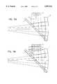
- FIGS. 5A and 5Bare side schematic views showing effective viewing angles in the absence of contrast correction.
- FIG. 6is a side schematic view showing corrected viewing angles.
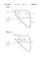
- An embodiment of the visual displaycomprises, as shown in FIG. 1, an image generator 2, a fold mirror 1 positioned to receive the image light from the image generator 2 and to reflect such image light and a reflective combiner 4 situated to receive the image light from the fold mirror 1, reflect such image light, which may be combined with light rays transmitted through the reflective combiner 4 from the ambient environment and transmit the combined environmental light rays and image light through the fold mirror 1 to the eye 5 of the user.
- An optical path 6 of the image light from the image generator 2 to the eye 5is depicted in FIG. 1.
- the present inventionprovides a substantially on-axis configuration.
- the image light from the image generatorimpinges the fold mirror at an angle 102 of about 45° (preferably, plus or minus about 5°) and/or the tangent plane 104 at the centroid 106 of the combiner 4 is at an angle 108 of about 90° (preferably, plus or minus about 5°) with respect to the output plane 100 of the image generator 2.
- An on-axis systemavoids a keystone distortion in the image (and thus avoids the requirement for additional optics if the distortion is to be corrected).
- the image lightpasses substantially directly (i.e., without passing through a intervening optical element) from the image generator to the fold mirror and/or from the fold mirror to the combiner.
- FIG. 2An embodiment illustrated in FIG. 2, includes an optical element, such as a field curvature correction lens 7, placed between the image generator 2 and fold mirror 1.
- the lens 7is a plano-convex lens with its flat surface oriented toward the image plane of the image generator.
- the various components of the depicted embodimentswill be described below in greater detail.
- separate imagesare generated and transmitted to each eye of the, user so that, in one embodiment, there will be two sets of components, depicted in the FIGS. 1 or 2, one for each eye.
- the image generator 2can be any of a plurality of imagining devices including a cathode-ray tube (CRT), light emitting diode (LED) array, liquid crystal display (LCD), field emissive device (FED), monochrome image source such as a monochrome CRT, which may be used in connection with a liquid crystal color shutter, as well as laser devices such as laser diode arrays.
- an LCD deviceincludes the capability for being backlit using any of a number of backlighting devices (not shown) such as incandescent lighting, fluorescent lighting, electro-luminescent and ambient lighting.
- the image generatorcan be a monochrome or color image source.
- a colorization elementsuch as a liquid crystal color shutter can be used, e.g., to convert a monochrome image into a frame sequential color image.
- a color shutter systemis provided, for example, in Tektronix EX100HD 1 inch Color Display System.
- a color LCDsuch as the Seiko Epson FO7KM200, 138,000 pixel, 0.7" diagonal, backlit LCD can be used, although other devices are also operable.
- the image generator 2generates an image under control of an image source 10 communicating with the image generator over a communication link 12.
- the image generatorcan receive image information from sources such as a computer, video cassette recorder (VCR), laser disc, video camera and the like.
- the communication linkcan be a cable, optical fiber or can be a wireless link, such as an infrared or a radio communication link.
- the image generator 2receives image information from a portable computer, running 3-dimensionally displayed software communicating over a cable link.
- the image generator 2is mounted substantially above the fold mirror 1 (meaning vertically above, when the device is oriented so that the axis between the eye position 5 and combiner 4 is substantially horizontal).
- the image lighttravels downward from the image generator 2 towards the fold mirror 1.
- the image lightis at least partially reflected by the fold mirror 1 in a substantially horizontal direction away from the eye of the user 5 and towards the combiner 4.
- the image lightis at least partially reflected back towards the fold mirror 1.
- light from the environmentpasses through the substantially transparent combiner 4 and travels along with the image light reflected from the combiner 4 to produce combined light.
- the combineris substantially fully reflective and substantially non-transmissive (so that, in this context, "combiner” is used only for convenience).
- the image light and/or the combined lightis at least partially transmitted through the fold mirror 1 towards the eye of the user 5.
- the amount of light, if any, which passes from the surrounding environment to the eyes of the observercan be at least partially controlled by the coatings placed on the surfaces of the combiner and the fold mirror.
- holographic optical elementscan be used to make the fold mirror and/or the combiner.
- Various holographic and non-holographic techniquescan be used for these purposes, as described more fully below and, as described, for example, in U.S. patent application 08/150,966 filed Nov. 12, 1993 for "Optically Corrected Helmet Mounted Display” and the parent application thereof, Ser. No. 07/832,237, filed Feb. 7, 1992, now U.S. Pat. No. 5,303,085, both of which are incorporated herein by reference.
- the fold mirror 1is a flat, partial reflector. In the depicted embodiment, it is positioned at approximately 45° with respect to the optical path of the image light 6.
- the fold mirrorreflects the projected image from the image source in a direction away from the eye 5 and towards the combiner.
- the fold mirroralso allows at least a portion of the light reflected from the combiner to pass through the fold mirror to the eye.
- the fold mirroris configured to reflect light evenly across the visible spectrum, (approximately 450 to 650 nanometer wavelengths).
- the fold mirroris a 50% splitter (reflecting 50% of light and passing 50% of light). It can be made holographically, dielectrically or metallically.
- the fold mirrorcan be formed using glass or plastic substrates, as well as other substantially transparent materials such as crystalline material, polycrystalline material, transparent ceramics and the like.
- the surface of the fold mirror which faces the image generatoris, typically, the reflective surface.
- the surface which is opposite the reflective surfacepreferably has an anti-reflective coating. The anti-reflective coating is useful in preventing a ghosting reflection from that surface.
- Holographic and dielectric fold mirrorscan be made to selectively reflect different polarizations at higher rates, and when used with wave retardation materials can achieve very high throughput efficiencies, such as described in patent application PCT/US94/01391.
- the fold mirror capbe produced either from vapor deposition of metallic or dielectric materials on the reflective side, and an anti-reflective coating such as Magnesium Fluoride using the same vapor deposition process. It can also be manufactured using holographic photopolymers or dichromatic gelatin (DCG) for the reflective surface. The anti-reflective surface is vapor deposited onto the back surface of the fold mirror.
- an anti-reflective coatingsuch as Magnesium Fluoride
- the combiner 4is a fully or partially reflective optical element. In one embodiment, it is spherically or aspherically curved preferably having a radius of curvature between about 50 mm and about 80 mm, more preferably between about 55 mm and about 70 mm and most preferably about 67 mm.
- the combiner 4serves as the primary magnification element for the image light.
- An optical elementis referred to as being a "powered" element if it provides image magnification.
- this itemis referred to as a "combiner”
- the combinermay be used without providing for a combination of image light with environmental light, as described more fully below.
- the combinercan be formed on a substrate of glass, plastic, or other transparent or partially transparent material or, when isolation from environmental light is desired, from opaque or substantially opaque substrates such as metal, non-transparent ceramics, plastics or glass and the like.
- the combinercan be made holographically using photopolymers, dichromated gelatin (DCG) or other similar holographic materials.
- holographic elementscan be finely tuned to reflect specific bands of wavelengths and transmit other wavelengths.
- the combineris tuned to achieve high reflection of red, green and blue wavelengths which are the wavelengths output by the image generator (and which, when combined, produce full color images).
- the holographic combineris a single line or multi-line holographic device, which can be tuned to reflect one or more wavelengths.
- a three-line holographic devicecan be tuned to reflect wavelengths of, e.g., approximately 480, 545 and 630 nanometers (plus or minus about 20 nanometers). Other wavelengths, such as wavelengths from the environment other than those in a narrow range around 480, 545 and 630 nanometers, will be transmitted through the combiner, towards the eye of the user with a high degree of transmissivity.
- the hologramcan be configured to reflect more, fewer or different wavelengths.
- Combinercan also be made using broadband dielectric technology. These combiners are made through the deposition of successive layers of dielectric material such as silicon dioxide and titanium dioxide. This type of coating can be provided so as to evenly reflect across the visible spectrum, such as evenly reflecting wavelengths between approximately 450 nanometers and 650 nanometers. Such evenness of reflection is particularly useful in maintaining color integrity of the image. Combiners made with a broadband dielectric coating are less efficient and less transmissive than holographic combiners and thus are useful in applications where high transmissivity is not required (such as virtual reality applications in which environmental light is not desired). Fully or almost fully immersive dielectric combiners can be made by dipping the combiner substrate into a light absorbing dye. The dying process can be altered to produce combiners of a given desired transmissivity specification, for example, about 1%.
- a combinercan also be formed on a substrate using an aluminum or other metallic coating in order to achieve the desired reflectivity of the combiner.
- These materialsare relatively inexpensive compared with holographic or dielectric combiners but are not as efficient. These combiners are easily made to be fully immersive and, by decreasing the thickness of the coating, can be made to be transmissive as well.
- the magnification provided by the combiner 4is configured so that center of the image from the image generator appears to the user, to have an infinite focus, (i.e., appears to be in focus to the user when the user is focusing his or her eyes at a far, essentially infinite, distance).
- portions of the image which are not at the centerhave a focus, perceived by the user, at some point closer than that at the center of the image.
- this differencewill increase as one progresses farther from the center of the generated image.
- this difference in perceived focal distanceis undesirable since, e.g., it forces the user to constantly shift his or her eye focus when viewing different portions of the generated image.
- the additional optical elementis positioned somewhere along the optical path between the image generator and the eye of the user. In the embodiment of FIG. 2, it is placed between the image generator 2 and the fold mirror 1. In the embodiment depicted in FIG. 2, the additional optical element is a plano-convex (PCX) lens.
- PCXplano-convex
- a meniscus lense.g., a negative meniscus lens can be used to simultaneously correct field curvature and to aim the image light in a more favorable direction. Aiming the image light can be useful for a number of purposes, including maintaining high contrast images, as described below. Image rays exiting from the image generator near normal (90° ⁇ about 10° with respect to the image plane) often have the highest contrast ratio.
- loss of contrastcan be reduced or eliminated by providing an optical element which accepts light rays at normal incidence from the LCD and redirects the light so as to enter the field curvature correction lens (where present) at the required angles and so as to produce the desired magnification and/or field curvature correction.
- FIG. 6depicts one such apparatus which provides a negative meniscus lens 36, preferably adjacent and/or contacting the output plane of the image generator 2.
- the negative meniscus lensis formed by an upper surface 37 of device 36 while a lower surface 37' acts as the field curvature correction lens.
- the effect of the negative meniscus lensis to provide an effective viewing angle for all portions of the image generated by the image generator 2 which is a relatively low angle (with respect to the normal direction from the output plane of the image generator) such as less than about 10°, preferably less than about 5° and more preferably less than about 3° from normal.
- Other optical elements which can achieve this manipulationare diffractive optical elements (DOEs), fresnel lenses and other refractive optical elements.
- DOEsdiffractive optical elements
- fresnel lensesfresnel lenses
- other refractive optical elementsrefractive optical elements.
- a diffractive optical elementWhen a diffractive optical element is used it can be placed directly on the LCD surface or on the field curvature correction lens or on a separate element, e.g., located between the image generator 2 and the field curvature correction lens. Such a diffractive optical element would receive light rays at normal incidence from the image generator 2 and redirect the rays through diffraction, to the proper
- Aiming the image raysis achieved using a diffractive optical element (such as a zone plate or hologram) or a Fresnel optic acting as a negative lens to accept collimated light, at substantially normal incidence from the image source, redirect it into a divergent beam which is then recollimated by the field curvature correction lens.
- a diffractive optical elementsuch as a zone plate or hologram
- a Fresnel optic acting as a negative lensto accept collimated light, at substantially normal incidence from the image source, redirect it into a divergent beam which is then recollimated by the field curvature correction lens.
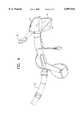
- FIGS. 3 and 4depict the use of the elements of FIG. 2 in a head mounted display.
- the opticsare fully or partially protected by being enclosed in a shroud 12, preferably with separate shrouds 12a and 12b for each eye as described in PCT application PCT/US94/09819 for Personal Visual Display System, filed on an even date herewith and incorporated herein by reference.
- a coveringsuch as visor top 14 further shields from stray light and protects the optical elements from dust or other contamination.
- the deviceis held in position by strap 16 and a forehead brace 18.
- the present inventionprovides for a high quality visual display which can combine a generated image with environmental light, but which is nevertheless lightweight and of reduced complexity and cost.
- the generated imageis magnified but is also presented to the user with a substantially flat focal field.
- the inventionprovides for high quality image and a lightweight device at least partially by reducing or minimizing the number of components
- certain additional optical componentscan be used if desired such as image intensifiers, depixelators and diffractive optical elements and Fresnel optics.
- a depixelatorWhen a depixelator is used, it can be provided as a crossed diffraction grating located parallel to the pixel plane of an image generator to receive, diffract, and transmit and thereby depixelate the light image from the image generator.
- the spatial frequency of the crossed diffraction gratingis constructed such that this spatial frequency multiplied by the shortest wavelength of the image light that is used approximately equals the center-to-center distance between adjacent pixels in the pixel plane of the image generator divided by twice the optical distance between the crossed diffraction grating and the pixel plane of the image generator.
- the modulation depth of the crossed diffraction gratingfall within the range of 80% to 120% and that the crossed diffraction grating be sinusoidal or slightly squared.
- the intensifiercan be provided as follows. If the light from the image generator is S polarized, a phase retarder, such as a quarter-wave plate or a polarization rotator, such as a liquid crystal device is positioned so that the S polarized image light reflected from the fold mirror is transmitted through e.g., a quarter-wave plate and retarded by one-quarter wave in order to exit the quarter-wave plate as circularly polarized image light.
- a phase retardersuch as a quarter-wave plate or a polarization rotator, such as a liquid crystal device
- the reflective combineris situated to receive the circularly polarized image light from the quarter-wave plate, reflect such circularly polarized image light, combine such circularly polarized image light with light rays transmitted through said reflective combiner from the surrounding environment, and transmit the combined environmental light rays and circularly polarized image light through the quarter-wave plate, which again retards the circularly polarized image light by one-quarter wave so that it exits the quarter-wave plate as P polarized light which then passes through the fold mirror with the environmental light rays and subsequently reaches the eye position of the user, as also do the environmental light rays with which the image light has been combined.
- the quarter-wave plateis attached to the reflective combiner.
- Quarter-wave platesare made from plastics and crystals or constructed holographically.
- a plastic wave plateis, however, more dispersive, and has lower optical properties than a crystalline or holographic wave plate.
- the user-mounted displaycomprises a first phase retarder such as a quarter-wave plate or a polarization rotator, located so that the P polarized image light from an image generator is transmitted through said first quarter-wave plate and retarded by one-quarter wave in order to exit the first quarter-wave plate as circularly polarized image light; a second quarter-wave plate positioned so that the circularly polarized image light from the first quarter-wave plate is transmitted through said second quarter-wave plate and retarded by one quarter-wave in order to exit the second quarter-wave plate as S polarized image light.
- a first phase retardersuch as a quarter-wave plate or a polarization rotator
- the fold mirrorreceives the S polarized image light from the second quarter-wave plate and reflects such S polarized image light through the second quarter-wave plate where the S polarized image light will again be retarded by one-quarter wave and, consequently, exit said second quarter-wave plate as circularly polarized image light.
- the reflective combinerreceives the circularly polarized image light from the second quarter-wave plate, reflects such circularly polarized image light, combines such circularly polarized image light, combines such circularly polarized image light with light rays transmitted through the combiner from the surrounding environment, and transmits the combined environmental light rays and circularly polarized image light through the second quarter-wave plate, which again retards the circularly polarized image light by one-quarter wave so that it exits the second quarter-wave plate as P polarized image light which then passes through the fold mirror with the environmental light rays and subsequently reaches the eye position of the user, as also do the environmental light rays with which the image light has been combined.
- the second quarter-wave platecan optionally be laminated to the fold mirror. This has the advantage of reducing the number of components which must be optically aligned. Additionally, it creates fewer surfaces on which an anti-reflective coating must be placed.
- the depicted configurationis an on-axis system
- the present inventioncan also be used in connection with an off-axis system.
- the depicted embodimentinvolves a binocular or biocular configuration a monocular configuration can also be used.
- the depicted embodimentshows a head-mounted display, other mounting techniques can be used such as a helmet mounted, fixed-eyepiece displays or the like.
Landscapes
- Physics & Mathematics (AREA)
- General Physics & Mathematics (AREA)
- Optics & Photonics (AREA)
Abstract
Description
This application is a continuation-in-part of Ser. No. 08/307,669, filed Apr. 21, 1995, now U.S. Pat. No. 5,864,326 which is the U.S. National Phase of PCT/US94/01390, filed Feb. 7, 1994, for "DEPIXELATED VISUAL DISPLAY" and is further a continuation-in-part of Ser. No. 08/150,966 filed Nov. 12, 1993, now abandoned, for "OPTICALLY CORRECTED ELEMENT MOUNTED DISPLAY" which is a divisional of Ser. No. 07/832,237, filed Feb. 7, 1992, now U.S. Pat. No. 5,303,085.
This invention relates to visual displays which preferably can combine generated images with a view of the environment surrounding a user and transmit such combined visual information to the eye of the user.
It is often desirable to provide visual information to a living being. Frequently, one wishes to superimpose such visual information upon the being's view of the real world. In other applications, it is desired to shield the user from a view of the environment, providing an exclusive view of the visual information.
Such displays include a number of components including, in a form known as a folded catadioptric head-mounted display, an image generator, a beam splitting fold mirror which receives the image light from the image generator, often via a series of lenses or other optical elements, and sends a fraction, designated the reflected fraction, of such image light to a reflective combiner that is either non-transmissive or both allows light from the real world to pass through such combiner and reflects the image light such that both the real-world light and the image light are transmitted through the beam splitter to the eye of the user, often via another series of lenses or other optical elements. The beam splitter will transmit a fraction, designated the transmitted fraction, of the image light reflected from the combiner. In embodiments in which the combiner is at least partially transmissive, a fraction of the real-world light is also transmitted by the beam splitter.
Previous devices included a number of additional components. Some devices have included corrective optical elements. Other devices have included a depixelator, e.g., as described in PCT/US94/01390 filed Feb. 7, 1994 for "Depixelated Visual Display" (incorporated herein by reference). Still other devices have included apparatus for intensifying the visual display such as those described in PCT/US94/01391, filed Feb. 7, 1994 for "Intensified Visual Display" (incorporated herein by reference).
In general, there are certain disadvantages to including components other than an image generator, beam splitter and reflective combiner. In most cases, each such additional item will contribute to the increased weight of the display device. When the display device is intended to be mounted on the user's head, such additional weight can contribute to discomfort and detract from the ability to move the head quickly and naturally as is desired for virtual reality applications. Furthermore, such additional devices typically must be correctly and precisely aligned and the difficulty and burden of alignment, both during the original manufacture and during any repair or maintenance that may be needed, is compounded by the number of additional components which are included in the device. Furthermore, both the optical design and the mechanical design become complicated when such additional components are included. Moreover, additional components typically increase the cost of the final device.
Accordingly, it would be useful to provide a visual display apparatus which has a reduced or minimized number of components and yet provides a visual display transmitted to the eye of the user having a desirably high quality and intensity of image.
One embodiment of the invention is a head-mounted display (HMD) that can project an image from an image generator such as a cathode ray tube (CRT) or a liquid crystal display (LCD) to one of each of the eyes of the observer or both transmit such an image and combine it with a direct view of the surrounding environment. The combiner images a CRT or LCD display surface mounted above the eye with a simple metallic, dielectric or holographic fold mirror reflecting the image towards the combiner.
According to one aspect of the present invention, the device simplifies the imaging optics by reducing the number of elements to three or fewer. One embodiment of the invention consists of an image generator such as a CRT or LCD, a combiner such as a spherical metallic, dielectric or holographically made combiner or collimator-combiner and a fold mirror such as a metallic, dielectric or holographically made fold mirror.
In one embodiment, no additional optical elements are needed to achieve the desired high quality image. Preferably, the visual display is simplified and made lightweight and less expensive by eliminating the need for certain optic elements such as relay lenses or additional corrective refractive optics. In one embodiment, a visual display provides for monochromatic and/or three-color display without refractive optics, such as by using reflective imaging optics only. In another embodiment, a single additional optical element is provided. In one embodiment, the additional optical element is provided to accommodate the curved reflecting surface of the combiner and provide an essentially flat focal field to the user. In another embodiment, a depixelator and/or an image intensifier can be provided.
FIG. 1 is a side elevational schematic view of a visual display device according to one embodiment of the present invention;
FIG. 2 is a side elevational schematic view of a visual display according to one embodiment of the present invention;
FIG. 3 is a perspective view, showing a head-mounted display device according to one embodiment of the present invention;
FIG. 4 is a side view, partially cut away, showing a head-mounted display device according to one embodiment of the present invention;
FIGS. 5A and 5B are side schematic views showing effective viewing angles in the absence of contrast correction; and
FIG. 6 is a side schematic view showing corrected viewing angles.
An embodiment of the visual display comprises, as shown in FIG. 1, animage generator 2, afold mirror 1 positioned to receive the image light from theimage generator 2 and to reflect such image light and areflective combiner 4 situated to receive the image light from thefold mirror 1, reflect such image light, which may be combined with light rays transmitted through thereflective combiner 4 from the ambient environment and transmit the combined environmental light rays and image light through thefold mirror 1 to theeye 5 of the user. Anoptical path 6 of the image light from theimage generator 2 to theeye 5 is depicted in FIG. 1. Preferably the present invention provides a substantially on-axis configuration. In the on-axis configuration of an embodiment of the present invention, the image light from the image generator impinges the fold mirror at anangle 102 of about 45° (preferably, plus or minus about 5°) and/or thetangent plane 104 at thecentroid 106 of thecombiner 4 is at anangle 108 of about 90° (preferably, plus or minus about 5°) with respect to theoutput plane 100 of theimage generator 2. An on-axis system avoids a keystone distortion in the image (and thus avoids the requirement for additional optics if the distortion is to be corrected). In one embodiment, the image light passes substantially directly (i.e., without passing through a intervening optical element) from the image generator to the fold mirror and/or from the fold mirror to the combiner.
An embodiment illustrated in FIG. 2, includes an optical element, such as a fieldcurvature correction lens 7, placed between theimage generator 2 andfold mirror 1. In the depiction of FIG. 2, thelens 7 is a plano-convex lens with its flat surface oriented toward the image plane of the image generator. The various components of the depicted embodiments will be described below in greater detail. Preferably, separate images are generated and transmitted to each eye of the, user so that, in one embodiment, there will be two sets of components, depicted in the FIGS. 1 or 2, one for each eye.
Theimage generator 2 can be any of a plurality of imagining devices including a cathode-ray tube (CRT), light emitting diode (LED) array, liquid crystal display (LCD), field emissive device (FED), monochrome image source such as a monochrome CRT, which may be used in connection with a liquid crystal color shutter, as well as laser devices such as laser diode arrays. Preferably, an LCD device includes the capability for being backlit using any of a number of backlighting devices (not shown) such as incandescent lighting, fluorescent lighting, electro-luminescent and ambient lighting. The image generator can be a monochrome or color image source. In one embodiment, a colorization element such as a liquid crystal color shutter can be used, e.g., to convert a monochrome image into a frame sequential color image. A color shutter system is provided, for example, in Tektronix EX100HD 1 inch Color Display System. In one embodiment, a color LCD such as the Seiko Epson FO7KM200, 138,000 pixel, 0.7" diagonal, backlit LCD can be used, although other devices are also operable. Theimage generator 2 generates an image under control of an image source 10 communicating with the image generator over a communication link 12. The image generator can receive image information from sources such as a computer, video cassette recorder (VCR), laser disc, video camera and the like. The communication link can be a cable, optical fiber or can be a wireless link, such as an infrared or a radio communication link. In one embodiment, theimage generator 2 receives image information from a portable computer, running 3-dimensionally displayed software communicating over a cable link.
In the depicted embodiment, theimage generator 2 is mounted substantially above the fold mirror 1 (meaning vertically above, when the device is oriented so that the axis between theeye position 5 andcombiner 4 is substantially horizontal). With reference to this configuration, the image light travels downward from theimage generator 2 towards thefold mirror 1. The image light is at least partially reflected by thefold mirror 1 in a substantially horizontal direction away from the eye of theuser 5 and towards thecombiner 4. At thecombiner 4, the image light is at least partially reflected back towards thefold mirror 1. In an embodiment in which the user will simultaneously view the image or the environmental light, light from the environment passes through the substantiallytransparent combiner 4 and travels along with the image light reflected from thecombiner 4 to produce combined light. In an embodiment in which the user will view only the generated image, without being able to view the environment (referred to as an "immersive" device), the combiner is substantially fully reflective and substantially non-transmissive (so that, in this context, "combiner" is used only for convenience). The image light and/or the combined light is at least partially transmitted through thefold mirror 1 towards the eye of theuser 5. The amount of light, if any, which passes from the surrounding environment to the eyes of the observer can be at least partially controlled by the coatings placed on the surfaces of the combiner and the fold mirror.
A number of technologies can be used to form thefold mirror 1 and thecombiner 4. In some devices, holographic optical elements (HOEs) can be used to make the fold mirror and/or the combiner. Various holographic and non-holographic techniques can be used for these purposes, as described more fully below and, as described, for example, in U.S. patent application 08/150,966 filed Nov. 12, 1993 for "Optically Corrected Helmet Mounted Display" and the parent application thereof, Ser. No. 07/832,237, filed Feb. 7, 1992, now U.S. Pat. No. 5,303,085, both of which are incorporated herein by reference.
Thefold mirror 1 is a flat, partial reflector. In the depicted embodiment, it is positioned at approximately 45° with respect to the optical path of theimage light 6. The fold mirror reflects the projected image from the image source in a direction away from theeye 5 and towards the combiner. The fold mirror also allows at least a portion of the light reflected from the combiner to pass through the fold mirror to the eye.
Preferably, the fold mirror is configured to reflect light evenly across the visible spectrum, (approximately 450 to 650 nanometer wavelengths). In one embodiment, the fold mirror is a 50% splitter (reflecting 50% of light and passing 50% of light). It can be made holographically, dielectrically or metallically. The fold mirror can be formed using glass or plastic substrates, as well as other substantially transparent materials such as crystalline material, polycrystalline material, transparent ceramics and the like. The surface of the fold mirror which faces the image generator is, typically, the reflective surface. The surface which is opposite the reflective surface preferably has an anti-reflective coating. The anti-reflective coating is useful in preventing a ghosting reflection from that surface. Holographic and dielectric fold mirrors can be made to selectively reflect different polarizations at higher rates, and when used with wave retardation materials can achieve very high throughput efficiencies, such as described in patent application PCT/US94/01391.
In one embodiment, the fold mirror cap be produced either from vapor deposition of metallic or dielectric materials on the reflective side, and an anti-reflective coating such as Magnesium Fluoride using the same vapor deposition process. It can also be manufactured using holographic photopolymers or dichromatic gelatin (DCG) for the reflective surface. The anti-reflective surface is vapor deposited onto the back surface of the fold mirror.
Thecombiner 4 is a fully or partially reflective optical element. In one embodiment, it is spherically or aspherically curved preferably having a radius of curvature between about 50 mm and about 80 mm, more preferably between about 55 mm and about 70 mm and most preferably about 67 mm. Preferably, thecombiner 4 serves as the primary magnification element for the image light. An optical element is referred to as being a "powered" element if it provides image magnification. Although, for convenience, this item is referred to as a "combiner", in some embodiments the combiner may be used without providing for a combination of image light with environmental light, as described more fully below. The combiner can be formed on a substrate of glass, plastic, or other transparent or partially transparent material or, when isolation from environmental light is desired, from opaque or substantially opaque substrates such as metal, non-transparent ceramics, plastics or glass and the like.
In one embodiment, the combiner can be made holographically using photopolymers, dichromated gelatin (DCG) or other similar holographic materials. As is well known in the art, holographic elements can be finely tuned to reflect specific bands of wavelengths and transmit other wavelengths. In one embodiment, the combiner is tuned to achieve high reflection of red, green and blue wavelengths which are the wavelengths output by the image generator (and which, when combined, produce full color images). In one embodiment, the holographic combiner is a single line or multi-line holographic device, which can be tuned to reflect one or more wavelengths. For example, a three-line holographic device can be tuned to reflect wavelengths of, e.g., approximately 480, 545 and 630 nanometers (plus or minus about 20 nanometers). Other wavelengths, such as wavelengths from the environment other than those in a narrow range around 480, 545 and 630 nanometers, will be transmitted through the combiner, towards the eye of the user with a high degree of transmissivity. Depending on the application, the hologram can be configured to reflect more, fewer or different wavelengths. Although digital holography is an operable technique, it is currently believed that this technique, which can be expensive to implement, is not needed to achieve the high-quality image of the present invention, and accordingly, a traditional (non-digital or non-synthetic) technique is presently preferred, when holograms are to be used for the combiner.
Combiner can also be made using broadband dielectric technology. These combiners are made through the deposition of successive layers of dielectric material such as silicon dioxide and titanium dioxide. This type of coating can be provided so as to evenly reflect across the visible spectrum, such as evenly reflecting wavelengths between approximately 450 nanometers and 650 nanometers. Such evenness of reflection is particularly useful in maintaining color integrity of the image. Combiners made with a broadband dielectric coating are less efficient and less transmissive than holographic combiners and thus are useful in applications where high transmissivity is not required (such as virtual reality applications in which environmental light is not desired). Fully or almost fully immersive dielectric combiners can be made by dipping the combiner substrate into a light absorbing dye. The dying process can be altered to produce combiners of a given desired transmissivity specification, for example, about 1%.
A combiner can also be formed on a substrate using an aluminum or other metallic coating in order to achieve the desired reflectivity of the combiner. These materials are relatively inexpensive compared with holographic or dielectric combiners but are not as efficient. These combiners are easily made to be fully immersive and, by decreasing the thickness of the coating, can be made to be transmissive as well.
In one embodiment, the magnification provided by thecombiner 4 is configured so that center of the image from the image generator appears to the user, to have an infinite focus, (i.e., appears to be in focus to the user when the user is focusing his or her eyes at a far, essentially infinite, distance). In many configurations, portions of the image which are not at the center have a focus, perceived by the user, at some point closer than that at the center of the image. Typically, this difference will increase as one progresses farther from the center of the generated image. In many applications this difference in perceived focal distance is undesirable since, e.g., it forces the user to constantly shift his or her eye focus when viewing different portions of the generated image.
In some embodiments it may be preferable to accept a certain amount of difference in focal distance across the generated image, e.g., in order to reduce or minimize the total weight of the visual display device, the cost, complexity and the like. In some applications, however, it is desired to include an additional optical element in order to correct this optical characteristic and present the user with a substantially flat focal field for the generated image. Embodiments of the invention can be used to reduce the aberrations and distortions produced by the spherical combiner such as image field curvature. The embodiment of FIG. 2 depicts one approach for achieving this correction. In these embodiments, additionaloptical element 7 is positioned somewhere along the optical path between the image generator and the eye of the user. In the embodiment of FIG. 2, it is placed between theimage generator 2 and thefold mirror 1. In the embodiment depicted in FIG. 2, the additional optical element is a plano-convex (PCX) lens.
In another embodiment, a meniscus lens, e.g., a negative meniscus lens can be used to simultaneously correct field curvature and to aim the image light in a more favorable direction. Aiming the image light can be useful for a number of purposes, including maintaining high contrast images, as described below. Image rays exiting from the image generator near normal (90°± about 10° with respect to the image plane) often have the highest contrast ratio.
As depicted in FIG. 5A, in configurations which include only animage generator 2, foldmirror 1 andcombiner 4, while the effective viewing angle 32 near the center of the image will be relatively close to normal (i.e., 90° to the image output plane), typically departing therefrom by no more than about 10°. However, portions of the image generated near the edges of theimage generator 2 have aneffective viewing angle 34 which is larger, and, in many cases, will be large enough (such as about 10° or more from normal) to have a degenerated or even reverse contrast. This typically presents the greatest problem when theimage generator 2 is a liquid crystal display since LCDs are often subject to loss of contrast at high viewing angles. This manifests itself in a perception of a low contrast or a reverse contrast image near the periphery or edge of the image. The problem of loss of contrast near the edge of the image is even more acute when a plano-convex lens 7 is included as depicted in FIG. 5B or when theimage generator 2 has a relatively larger size such as having a diagonal size of 1 inch or more (although some loss of contrast of the periphery may still occur for smaller image generators such as 0.7 inch diagonal image generators).
According to one embodiment of the present invention, loss of contrast can be reduced or eliminated by providing an optical element which accepts light rays at normal incidence from the LCD and redirects the light so as to enter the field curvature correction lens (where present) at the required angles and so as to produce the desired magnification and/or field curvature correction. FIG. 6 depicts one such apparatus which provides anegative meniscus lens 36, preferably adjacent and/or contacting the output plane of theimage generator 2. Preferably, the negative meniscus lens is formed by anupper surface 37 ofdevice 36 while a lower surface 37' acts as the field curvature correction lens. As can be seen from FIG. 6 the effect of the negative meniscus lens is to provide an effective viewing angle for all portions of the image generated by theimage generator 2 which is a relatively low angle (with respect to the normal direction from the output plane of the image generator) such as less than about 10°, preferably less than about 5° and more preferably less than about 3° from normal. Other optical elements which can achieve this manipulation are diffractive optical elements (DOEs), fresnel lenses and other refractive optical elements. When a diffractive optical element is used it can be placed directly on the LCD surface or on the field curvature correction lens or on a separate element, e.g., located between theimage generator 2 and the field curvature correction lens. Such a diffractive optical element would receive light rays at normal incidence from theimage generator 2 and redirect the rays through diffraction, to the proper angles required by the plano-convex lens 7 used for field curvature correction.
Aiming the image rays is achieved using a diffractive optical element (such as a zone plate or hologram) or a Fresnel optic acting as a negative lens to accept collimated light, at substantially normal incidence from the image source, redirect it into a divergent beam which is then recollimated by the field curvature correction lens.
FIGS. 3 and 4 depict the use of the elements of FIG. 2 in a head mounted display. In one embodiment, the optics are fully or partially protected by being enclosed in a shroud 12, preferably withseparate shrouds visor top 14 further shields from stray light and protects the optical elements from dust or other contamination. In the depicted embodiment, the device is held in position bystrap 16 and aforehead brace 18.
In view of the above description, a number of advantages of the present invention can be seen. The present invention provides for a high quality visual display which can combine a generated image with environmental light, but which is nevertheless lightweight and of reduced complexity and cost. In one embodiment, the generated image is magnified but is also presented to the user with a substantially flat focal field.
A number of variations and modifications can also be used. Although the invention provides for high quality image and a lightweight device at least partially by reducing or minimizing the number of components, certain additional optical components can be used if desired such as image intensifiers, depixelators and diffractive optical elements and Fresnel optics.
When a depixelator is used, it can be provided as a crossed diffraction grating located parallel to the pixel plane of an image generator to receive, diffract, and transmit and thereby depixelate the light image from the image generator. Preferably, the spatial frequency of the crossed diffraction grating is constructed such that this spatial frequency multiplied by the shortest wavelength of the image light that is used approximately equals the center-to-center distance between adjacent pixels in the pixel plane of the image generator divided by twice the optical distance between the crossed diffraction grating and the pixel plane of the image generator.
It is preferable that the modulation depth of the crossed diffraction grating fall within the range of 80% to 120% and that the crossed diffraction grating be sinusoidal or slightly squared.
When the additional optical component is an image intensifier, the intensifier can be provided as follows. If the light from the image generator is S polarized, a phase retarder, such as a quarter-wave plate or a polarization rotator, such as a liquid crystal device is positioned so that the S polarized image light reflected from the fold mirror is transmitted through e.g., a quarter-wave plate and retarded by one-quarter wave in order to exit the quarter-wave plate as circularly polarized image light. The reflective combiner is situated to receive the circularly polarized image light from the quarter-wave plate, reflect such circularly polarized image light, combine such circularly polarized image light with light rays transmitted through said reflective combiner from the surrounding environment, and transmit the combined environmental light rays and circularly polarized image light through the quarter-wave plate, which again retards the circularly polarized image light by one-quarter wave so that it exits the quarter-wave plate as P polarized light which then passes through the fold mirror with the environmental light rays and subsequently reaches the eye position of the user, as also do the environmental light rays with which the image light has been combined. Optionally, the quarter-wave plate is attached to the reflective combiner.
The precise nature of the quarter-wave plate is not critical. It is, however, preferable to employ a single-order plate so that dependence on angle and wavelength is minimized. Quarter-wave plates are made from plastics and crystals or constructed holographically. A plastic wave plate is, however, more dispersive, and has lower optical properties than a crystalline or holographic wave plate.
If the light from the image generator is P polarized, the user-mounted display comprises a first phase retarder such as a quarter-wave plate or a polarization rotator, located so that the P polarized image light from an image generator is transmitted through said first quarter-wave plate and retarded by one-quarter wave in order to exit the first quarter-wave plate as circularly polarized image light; a second quarter-wave plate positioned so that the circularly polarized image light from the first quarter-wave plate is transmitted through said second quarter-wave plate and retarded by one quarter-wave in order to exit the second quarter-wave plate as S polarized image light. The fold mirror receives the S polarized image light from the second quarter-wave plate and reflects such S polarized image light through the second quarter-wave plate where the S polarized image light will again be retarded by one-quarter wave and, consequently, exit said second quarter-wave plate as circularly polarized image light. The reflective combiner receives the circularly polarized image light from the second quarter-wave plate, reflects such circularly polarized image light, combines such circularly polarized image light, combines such circularly polarized image light with light rays transmitted through the combiner from the surrounding environment, and transmits the combined environmental light rays and circularly polarized image light through the second quarter-wave plate, which again retards the circularly polarized image light by one-quarter wave so that it exits the second quarter-wave plate as P polarized image light which then passes through the fold mirror with the environmental light rays and subsequently reaches the eye position of the user, as also do the environmental light rays with which the image light has been combined.
The second quarter-wave plate can optionally be laminated to the fold mirror. This has the advantage of reducing the number of components which must be optically aligned. Additionally, it creates fewer surfaces on which an anti-reflective coating must be placed.
Although the depicted configuration is an on-axis system, the present invention can also be used in connection with an off-axis system. Although the depicted embodiment involves a binocular or biocular configuration a monocular configuration can also be used. Although the depicted embodiment shows a head-mounted display, other mounting techniques can be used such as a helmet mounted, fixed-eyepiece displays or the like.
Although the present invention has been described by way of a preferred embodiment and certain variations and modifications, other variations and modifications can also be used, the invention being defined by the following claims.
Claims (14)
1. Head-mounted visual display apparatus for a user, comprising:
an image generator which outputs image light, said image generator having a substantially planar output surface to output said image light in an image plane, said planar output surface being non-orthogonal to the plane of the user's eyes, wherein wavelengths of said image light are from approximately 480 nanometers to approximately 630 nanometers;
a fold mirror configured to reflect light evenly across the visible spectrum, positioned to receive the image light from the image generator and to reflect at least a first portion of said image light in a first direction;
a reflective combiner situated to receive said first portion of said image light from said fold mirror, reflect at least a second portion of said image light, combined with environmental light transmitted through the reflective combiner to produce combined light, wherein at least some of said combined light is transmitted through said fold mirror in a second direction to the eye position of the user, providing an optical path from said image generator to said fold mirror to said combiner, back through said fold mirror and to said eye position of the user;
said image generator and said reflective combiner being mounted on the head of said user at a level below the top of the head of said user;
wherein said visual display apparatus is provided in the absence of any optically active components between said image generator and said fold mirror.
2. An apparatus, as claimed in claim 1, wherein said image light includes red, green and blue light.
3. Head-mounted visual display apparatus for a user, comprising:
an image generator which outputs image light, said image generator having a substantially planar output surface to output said image light in an image plane, said planar output surface being non-orthogonal to the plane of the user's eyes;
a fold mirror configured to reflect light evenly across the visible spectrum, positioned to receive the image light from the image generator and to reflect at least a first portion of said image light in a first direction;
a reflective combiner situated to receive said first portion of said image light from said fold mirror, reflect at least a second portion of said image light, combined with environmental light transmitted through the reflective combiner to produce combined light, wherein at least some of said combined light is transmitted through said fold mirror in a second direction to the eye position of the user, providing an optical path from said image generator to said fold mirror to said combiner, back through said fold mirror and to said eye position of the user;
said image generator and said reflective combiner being mounted on the head of said user at a level below the top of the head of said user;
an optical element, distinct from said combiner and said fold mirror, positioned between said fold mirror and said combiner.
4. Apparatus, as claimed in claim 3, wherein said optical element positioned between said fold mirror and said combiner comprises a phase retarder.
5. An apparatus, as claimed in claim 3, wherein said optical element is positioned for receiving said image light from said image generator prior to said image light contacting said fold mirror.
6. Head-mounted visual display apparatus for a user, comprising:
an image generator which outputs image light, said image generator having a substantially planar output surface to output said image light in an image plane, said planar output surface being non-orthogonal to the plane of the user's eyes;
a fold mirror configured to reflect light evenly across the visible spectrum, positioned to receive the image light from the image generator and to reflect at least a first portion of said image light in a first direction;
a reflective combiner situated to receive said first portion of said image light from said fold mirror, reflect at least a second portion of said image light, combined with environmental light transmitted through the reflective combiner to produce combined light, wherein at least some of said combined light is transmitted through said fold mirror in a second direction to the eye position of the user, providing an optical path from said image generator to said fold mirror to said combiner, back through said fold mirror and to said eye position of the user;
said image generator and said reflective combiner being mounted on the head of said user at a level below the top of the head of said user;
a refractive optical element located between said image generator and the fold mirror
wherein said refractive optical element avoids a reduction in contrast in the image.
7. Head-mounted visual display apparatus for a user, comprising:
an image generator which outputs image light, said image generator having a substantially planar output surface to output said image light in an image plane, said planar output surface being non-orthogonal to the plane of the user's eyes;
a fold mirror configured to reflect light evenly across the visible spectrum, positioned to receive the image light from the image generator and to reflect at least a first portion of said image light in a first direction;
a reflective combiner situated to receive said first portion of said image light from said fold mirror, reflect at least a second portion of said image light, combined with environmental light transmitted through the reflective combiner to produce combined light, wherein at least some of said combined light is transmitted through said fold mirror in a second direction to the eve position of the user, providing an optical path from said image generator to said fold mirror to said combiner, back through said fold mirror and to said eye position of the user;
said image generator and said reflective combiner being mounted on the head of said user at a level below the top of the head of said user;
wherein one of a phase retarder and a polarization rotating device is positioned along the optical path.
8. Apparatus, as claimed in claim 7, wherein said phase retarder is a quarter-wave plate.
9. Head-mounted visual display apparatus for a user, comprising:
an image generator which outputs image light, said image generator having a substantially planar output surface to output said image light in an image plane, said planar output surface being non-orthogonal to the plane of the user's eyes;
a fold mirror configured to reflect light evenly across the visible spectrum positioned to receive the image light from the image generator and to reflect at least a first portion of said image light in a first direction;
a second mirror situated to receive said first portion of said image light from said fold mirror, reflect at least a second portion of said image light, wherein at least some of said image light is transmitted through said fold mirror in a second direction to the eve position of the user, providing an optical path from said image generator to said fold mirror to said second mirror to said eve position of the user;
said image generator and said second mirror being mounted on the head of said user at a level below the top of the head of said user;
wherein said second mirror is substantially non-transmissive.
10. Visual display apparatus for a user, comprising:
an image generator having a first output surface, which outputs image light;
a fold mirror positioned to receive the image light from the image generator and to reflect at least a first portion of said image light in a first reflected direction;
a magnifier situated to receive said first portion of said image light from said fold mirror, reflect and magnify at least a second portion of said image light combined with environmental light transmitted through the magnifier to produce combined light, wherein at least some of said combined light is transmitted through said fold mirror in a second reflected direction to the eye position of the user, providing an optical path from said image generator to said fold mirror to said magnifier to said eye position of the user; and
means which redirect light received at normal incidence, for preventing loss of contrast of said image.
11. Head-mounted visual display apparatus for a user, comprising:
an image generator which outputs image light, said image generator having a substantially planar output surface to output said image light in an image plane, said planar output surface being non-orthogonal to the plane of the user's eyes;
a fold mirror configured to reflect light evenly across the visible spectrum, positioned to receive the image light from the image generator and to reflect at least a first portion of said image light in a first direction;
a reflective combiner situated to receive said first portion of said image light from said fold mirror, reflect at least a second portion of said image light, combined with environmental light transmitted through the reflective combiner to produce combined light, wherein at least some of said combined light is transmitted through said fold mirror in a second direction to the eye position of the user, providing an optical path from said image generator to said fold mirror to said combiner, back through said fold mirror and to said eye position of the user;
said image generator and said reflective combiner being mounted on the head of said user at a level below the top of the head of said user;
an optical element positioned between said fold mirror and said combiner, wherein said optical element comprises a phase retarder.
12. Head-mounted visual display apparatus for a user, comprising:
an image generator which outputs image light, said image generator having a substantially planar output surface to output said image light in an image plane, said planar output surface being non-orthogonal to the plane of the user's eyes;
a fold mirror configured to reflect light evenly across the visible spectrum, positioned to receive the image light from the image generator and to reflect at least a first portion of said image light in a first direction;
a reflective combiner situated to receive said first portion of said image light from said fold mirror, reflect at least a second portion of said image light, combined with environmental light transmitted through the reflective combiner to produce combined light, wherein at least some of said combined light is transmitted through said fold mirror in a second direction to the eye position of the user, providing an optical path from said image generator to said fold mirror to said combiner, back through said fold mirror and to said eye position of the user;
said image generator and said reflective combiner being mounted on the head of said user at a level below the top of the head of said user;
wherein at least one of said fold mirror and reflective combiner provides an on-axis configuration for said visual display apparatus.
13. An apparatus, as claimed in claim 12, wherein said on-axis configuration includes one of: (a) said fold mirror being at an angle of approximately 45° to said planar output surface, and (b) said reflective combiner being at an angle of approximately 90° to said planar output surface.
14. Head-mounted visual display apparatus for a user, comprising:
an image generator which outputs image light, said image generator having a substantially planar output surface to output said image light in an image plane, said planar output surface being non-orthogonal to the plane of the user's eyes;
a fold mirror configured to reflect light evenly across the visible spectrum, positioned to receive the image light from the image generator and to reflect at least a first portion of said image light in a first direction;
a reflective combiner situated to receive said first portion of said image light from said fold mirror, reflect at least a second portion of said image light, combined with environmental light transmitted through the reflective combiner to produce combined light, wherein at least some of said combined light is transmitted through said fold mirror in a second direction to the eye position of the user, providing an optical path from said image generator to said fold mirror to said combiner, back through said fold mirror and to said eye position of the user;
said image generator and said reflective combiner being mounted on the head of said user at a level below the top of the head of said user;
said fold mirror and said reflective combiner are used for combining a wavelength of light from said image light with said wavelength of light transmitted through said reflective combiner.
Priority Applications (2)
| Application Number | Priority Date | Filing Date | Title |
|---|---|---|---|
| US08/416,840US6097543A (en) | 1992-02-07 | 1994-08-31 | Personal visual display |
| US08/484,857US5949583A (en) | 1992-02-07 | 1995-06-07 | Head-mounted display with image generator, fold mirror and mirror for transmission to the eye position of the user |
Applications Claiming Priority (4)
| Application Number | Priority Date | Filing Date | Title |
|---|---|---|---|
| US07/832,237US5303085A (en) | 1992-02-07 | 1992-02-07 | Optically corrected helmet mounted display |
| US15096693A | 1993-11-12 | 1993-11-12 | |
| PCT/US1994/009820WO1995021396A2 (en) | 1994-02-07 | 1994-08-31 | Personal visual display |
| US08/416,840US6097543A (en) | 1992-02-07 | 1994-08-31 | Personal visual display |
Related Parent Applications (2)
| Application Number | Title | Priority Date | Filing Date |
|---|---|---|---|
| US15221393AContinuation-In-Part | 1992-02-07 | 1993-11-12 | |
| US08/307,669Continuation-In-PartUS5864326A (en) | 1992-02-07 | 1994-02-07 | Depixelated visual display |
Related Child Applications (1)
| Application Number | Title | Priority Date | Filing Date |
|---|---|---|---|
| US08/484,857DivisionUS5949583A (en) | 1992-02-07 | 1995-06-07 | Head-mounted display with image generator, fold mirror and mirror for transmission to the eye position of the user |
Publications (1)
| Publication Number | Publication Date |
|---|---|
| US6097543Atrue US6097543A (en) | 2000-08-01 |
Family
ID=26848199
Family Applications (1)
| Application Number | Title | Priority Date | Filing Date |
|---|---|---|---|
| US08/416,840Expired - Fee RelatedUS6097543A (en) | 1992-02-07 | 1994-08-31 | Personal visual display |
Country Status (1)
| Country | Link |
|---|---|
| US (1) | US6097543A (en) |
Cited By (45)
| Publication number | Priority date | Publication date | Assignee | Title |
|---|---|---|---|---|
| US20020008675A1 (en)* | 2000-06-14 | 2002-01-24 | Theodore Mayer | Method and apparatus for seamless integration of images using a transmissive/reflective mirror |
| US6510005B1 (en)* | 1998-10-27 | 2003-01-21 | Irving S. Goldstein | Filter for illusion apparatus |
| US6614830B1 (en)* | 1999-07-02 | 2003-09-02 | Milton Bernard Hollander | Laser beam adjustment |
| US20040004584A1 (en)* | 2002-03-20 | 2004-01-08 | Raymond Hebert | Head-mounted viewing system for single electronic displays using biocular lens with binocular folding mirrors |
| US20050156173A1 (en)* | 1999-09-30 | 2005-07-21 | Semiconductor Energy Laboratory Co., Ltd. | Organic electroluminescent display device |
| US20050180021A1 (en)* | 2004-02-18 | 2005-08-18 | Interactive Imaging Systems, Inc. | Micro-display engine |
| US7119965B1 (en)* | 2003-02-24 | 2006-10-10 | University Of Central Florida Research Foundation, Inc. | Head mounted projection display with a wide field of view |
| US20060236121A1 (en)* | 2005-04-14 | 2006-10-19 | Ibm Corporation | Method and apparatus for highly secure communication |
| US20060236120A1 (en)* | 2005-04-14 | 2006-10-19 | Ibm Corporation | Method and apparatus employing stress detection for highly secure communication |
| US20060259100A1 (en)* | 2003-01-17 | 2006-11-16 | Andreas Hilburg | Light therapy device |
| US20080038702A1 (en)* | 2004-09-27 | 2008-02-14 | Claude Choquet | Body Motion Training and Qualification System and Method |
| US20080064326A1 (en)* | 2006-08-24 | 2008-03-13 | Stephen Joseph Foster | Systems and Methods for Casting Captions Associated With A Media Stream To A User |
| US20080199250A1 (en)* | 2007-02-21 | 2008-08-21 | Adc Telecommunications, Inc. | Coupler for Cable Trough |
| US20090295681A1 (en)* | 2008-05-27 | 2009-12-03 | Gm Global Technology Operations, Inc. | Virtual Image System for Windshields |
| US20100198867A1 (en)* | 1998-10-19 | 2010-08-05 | Sony Corporation | Information processing apparatus and method, information processing system, and providing medium |
| WO2013096052A2 (en) | 2011-12-19 | 2013-06-27 | Dolby Laboratories Licensing Corporation | Highly-extensible and versatile personal display |
| US20140098425A1 (en)* | 2008-12-02 | 2014-04-10 | Saab Ab | Head-up display for night vision goggles |
| WO2014120388A1 (en)* | 2013-01-31 | 2014-08-07 | Google Inc. | See-through near-to-eye display with eye prescription |
| USD714786S1 (en)* | 2014-02-18 | 2014-10-07 | Kopin Corporation | Electronic viewing device |
| CN104898283A (en)* | 2015-05-25 | 2015-09-09 | 青岛歌尔声学科技有限公司 | Ocular lens system and head-mounted display |
| US20150331246A1 (en)* | 2014-01-06 | 2015-11-19 | Avegant Corporation | Apparatus, system, and method for displaying an image using a plate |
| WO2016022732A1 (en)* | 2014-08-07 | 2016-02-11 | Microsoft Technology Licensing, Llc | Near eye display with a spherical mirror and a decoupled aspherical element |
| USD756010S1 (en)* | 2014-05-30 | 2016-05-10 | Hawk Importers, Inc. | Visor magnifier with LED |
| US20160266383A1 (en)* | 2013-11-06 | 2016-09-15 | Denso Corporation | Head-up display device |
| US9454008B2 (en) | 2013-10-07 | 2016-09-27 | Resonance Technology, Inc. | Wide angle personal displays |
| CN106464818A (en)* | 2014-01-06 | 2017-02-22 | 埃维根特公司 | Imaging a curved mirror and partially transparent plate |
| CN106605171A (en)* | 2014-05-19 | 2017-04-26 | 埃维根特公司 | Apparatus, system, and method for displaying an image using a plate |
| US9720231B2 (en) | 2012-09-26 | 2017-08-01 | Dolby Laboratories Licensing Corporation | Display, imaging system and controller for eyewear display device |
| US9823474B2 (en) | 2015-04-02 | 2017-11-21 | Avegant Corp. | System, apparatus, and method for displaying an image with a wider field of view |
| US9995857B2 (en) | 2015-04-03 | 2018-06-12 | Avegant Corp. | System, apparatus, and method for displaying an image using focal modulation |
| US20190025602A1 (en)* | 2017-07-20 | 2019-01-24 | Google Llc | Compact near-eye display optics for augmented reality |
| US10303242B2 (en) | 2014-01-06 | 2019-05-28 | Avegant Corp. | Media chair apparatus, system, and method |
| CN110095868A (en)* | 2019-03-19 | 2019-08-06 | 北京灵犀微光科技有限公司 | Eliminate the optical projection system and wearable device of the curvature of field |
| US10429646B2 (en) | 2015-10-28 | 2019-10-01 | Google Llc | Free space optical combiner with prescription integration |
| KR20200118203A (en)* | 2018-02-12 | 2020-10-14 | 매트릭스 리얼리티 테크놀로지 컴퍼니 리미티드 | Augmented reality device and optical system therefor |
| US10969675B1 (en) | 2019-06-10 | 2021-04-06 | Facebook Technologies, Llc | Optical assemblies having scanning reflectors for projecting augmented reality content |
| US11048087B2 (en)* | 2019-06-10 | 2021-06-29 | Facebook Technologies, Llc | Optical assemblies having polarization volume gratings for projecting augmented reality content |
| US11181815B1 (en) | 2019-06-11 | 2021-11-23 | Facebook Technologies, Llc | Optical devices including reflective spatial light modulators for projecting augmented reality content |
| US11201672B2 (en) | 2007-05-24 | 2021-12-14 | Federal Law Enforcement Development Services, Inc. | LED light fixture |
| US11200794B2 (en) | 2015-08-11 | 2021-12-14 | Federal Law Enforcement Development Services, Inc. | Function disabler device and system |
| US11265082B2 (en) | 2007-05-24 | 2022-03-01 | Federal Law Enforcement Development Services, Inc. | LED light control assembly and system |
| US11424781B2 (en) | 2009-04-01 | 2022-08-23 | Federal Law Enforcement Development Services, Inc. | Visible light communication transceiver glasses |
| US11474349B2 (en) | 2016-09-22 | 2022-10-18 | Denso Corporation | Head-up display device |
| US11552712B2 (en) | 2013-05-06 | 2023-01-10 | Federal Law Enforcement Development Services, Inc. | Network security and variable pulse wave form with continuous communication |
| US11783345B2 (en) | 2014-01-15 | 2023-10-10 | Federal Law Enforcement Development Services, Inc. | Cyber life electronic networking and commerce operating exchange |
Citations (186)
| Publication number | Priority date | Publication date | Assignee | Title |
|---|---|---|---|---|
| US2411933A (en)* | 1943-05-27 | 1946-12-03 | Charles E Morley | Goggles |
| US2955156A (en)* | 1957-05-24 | 1960-10-04 | Morton L Heilig | Stereoscopic-television apparatus for individual use |
| US2958258A (en)* | 1953-09-21 | 1960-11-01 | Technicolor Corp | Optical projection of beam controlled object fields |
| US3043910A (en)* | 1958-05-19 | 1962-07-10 | American Optical Corp | Fiber optical image transfer devices |
| US3212102A (en)* | 1962-05-14 | 1965-10-19 | Muller Erich | Anti-glare device |
| DE2009798A1 (en) | 1969-03-04 | 1970-09-10 | Pilkington Perkin-Elmer Ltd., Liverpool, Lancashire (Grossbritannien) | Reflection device for mirroring images of an object that is not in the observer's field of vision into the observer's field of vision |
| US3589795A (en)* | 1968-07-10 | 1971-06-29 | Matsushita Electric Industrial Co Ltd | Fiber optics element with oblique internal reflector means |
| US3614314A (en)* | 1967-03-21 | 1971-10-19 | Bendix Corp | Optical display means for an all-weather landing system of an aircraft |
| US3629870A (en)* | 1969-11-28 | 1971-12-28 | Herbert J Paisley | Instrument flying training device |
| US3874783A (en)* | 1972-08-02 | 1975-04-01 | American Optical Corp | Numerical aperture expansion in fiber optic devices |
| US3915548A (en)* | 1973-04-30 | 1975-10-28 | Hughes Aircraft Co | Holographic lens and liquid crystal image source for head-up display |
| US3923370A (en)* | 1974-10-15 | 1975-12-02 | Honeywell Inc | Head mounted displays |
| US3940204A (en)* | 1975-01-23 | 1976-02-24 | Hughes Aircraft Company | Optical display systems utilizing holographic lenses |
| US4021862A (en)* | 1975-06-02 | 1977-05-10 | Nuclear Associates, Inc. | Radiation eye shield |
| US4026641A (en)* | 1975-12-30 | 1977-05-31 | The United States Of America As Represented By The Secretary Of The Army | Toric reflector display |
| US4028725A (en)* | 1976-04-21 | 1977-06-07 | Grumman Aerospace Corporation | High-resolution vision system |
| US4042957A (en)* | 1974-11-29 | 1977-08-16 | Elliott Brothers (London) Limited | Display systems |
| US4048653A (en)* | 1974-10-16 | 1977-09-13 | Redifon Limited | Visual display apparatus |
| US4257062A (en)* | 1978-12-29 | 1981-03-17 | Meredith Russell W | Personalized audio-visual system |
| US4269476A (en)* | 1978-11-07 | 1981-05-26 | Thomson-Csf | Helmet-mounted display system |
| US4310849A (en)* | 1979-06-11 | 1982-01-12 | Glass Stuart M | Stereoscopic video system |
| GB2006463B (en) | 1977-10-17 | 1982-03-17 | Hughes Aircraft Co | Holographic one tube goggle |
| US4322135A (en)* | 1978-11-29 | 1982-03-30 | Pilkington P. E. Limited | Optical apparatus |
| US4348185A (en)* | 1980-02-14 | 1982-09-07 | The United States Of America As Represented By The Secretary Of The Navy | Wide angle infinity display system |
| US4361384A (en)* | 1980-06-27 | 1982-11-30 | The United States Of America As Represented By The Secretary Of The Army | High luminance miniature display |
| US4385803A (en)* | 1980-05-19 | 1983-05-31 | Elliott Brothers (London) Limited | Display units with periscopic arrangement |
| US4395731A (en)* | 1981-10-16 | 1983-07-26 | Arnold Schoolman | Television microscope surgical method and apparatus therefor |
| US4398799A (en)* | 1980-03-04 | 1983-08-16 | Pilkington P.E. Limited | Head-up displays |
| US4437113A (en)* | 1981-12-21 | 1984-03-13 | The United States Of America As Represented By The Secretary Of The Air Force | Anti-flutter apparatus for head mounted visual display |
| US4439157A (en)* | 1982-05-03 | 1984-03-27 | The United States Of America As Represented By The Secretary Of The Navy | Helmet mounted display projector |
| US4446480A (en)* | 1981-12-14 | 1984-05-01 | The United States Of America As Represented By The Secretary Of The Navy | Head position and orientation sensor |
| US4465347A (en)* | 1982-11-15 | 1984-08-14 | The United States Of America As Represented By The Secretary Of The Air Force | Helmet mounted telescope |
| US4468101A (en)* | 1981-05-29 | 1984-08-28 | Marconi Avionics Limited | Night vision goggles |
| US4550984A (en)* | 1982-02-26 | 1985-11-05 | Thomson Csf | Head-mounted or helmet-mounted sighting device |
| US4559555A (en)* | 1982-02-24 | 1985-12-17 | Arnold Schoolman | Stereoscopic remote viewing system |
| US4561723A (en)* | 1982-04-28 | 1985-12-31 | Tomy Kogyo Co., Inc. | Electronic stereoscopic viewing device |
| FR2517916B1 (en) | 1981-12-04 | 1986-01-17 | Thomson Csf | STEREOSCOPIC VISUALIZATION APPARATUS FOR USE WITH A HELMET VIEWFINDER |
| US4571628A (en)* | 1984-03-23 | 1986-02-18 | Thirstol Thornton | Portable video viewing assembly |
| GB2143948B (en) | 1983-07-23 | 1986-08-06 | Ferranti Plc | Apparatus for determining the direction of a line of sight |
| US4630321A (en)* | 1986-04-21 | 1986-12-23 | H. L. Bouton Company, Inc. | Safety spectacles with brow protector |
| US4633324A (en)* | 1985-01-23 | 1986-12-30 | Giulie James E | CRT shield |
| US4636866A (en)* | 1982-12-24 | 1987-01-13 | Seiko Epson K.K. | Personal liquid crystal image display |
| US4641931A (en)* | 1984-04-17 | 1987-02-10 | U.S. Philips Corporation | Dual magnification telescope |
| US4651201A (en)* | 1984-06-01 | 1987-03-17 | Arnold Schoolman | Stereoscopic endoscope arrangement |
| US4652870A (en)* | 1984-02-10 | 1987-03-24 | Gec Avionics Limited | Display arrangements for head-up display systems |
| US4695129A (en)* | 1983-05-26 | 1987-09-22 | U.S. Philips Corp. | Viewer having head mounted display unit for cinerama pictures |
| US4703522A (en)* | 1985-11-16 | 1987-11-03 | Carl-Zeiss-Stiftung | Laser safety eyeglasses |
| US4706117A (en)* | 1984-06-01 | 1987-11-10 | Arnold Schoolman | Stereo laser disc viewing system |
| US4711512A (en)* | 1985-07-12 | 1987-12-08 | Environmental Research Institute Of Michigan | Compact head-up display |
| US4726075A (en)* | 1986-12-04 | 1988-02-23 | Hinrichs Matthew T | Disposable side shield for eyeglasses |
| DE3628458A1 (en) | 1986-08-21 | 1988-02-25 | Dornier System Gmbh | DEVICE FOR SPACIOUS WATCHING THREE-DIMENSIONAL TV SCREENS |
| US4737972A (en)* | 1982-02-24 | 1988-04-12 | Arnold Schoolman | Stereoscopic fluoroscope arrangement |
| US4743200A (en)* | 1984-11-13 | 1988-05-10 | Cae Electronics, Ltd. | Fiber optic coupled helmet mounted display system |
| US4751746A (en)* | 1986-12-23 | 1988-06-21 | Rustin Robby J | Combination ear protector and sunshield attachment for glasses |
| US4753514A (en)* | 1986-05-12 | 1988-06-28 | Iota Instrumentation Co. | Headwear-mounted periscopic display device |
| US4757714A (en)* | 1986-09-25 | 1988-07-19 | Insight, Inc. | Speed sensor and head-mounted data display |
| US4761056A (en)* | 1987-03-27 | 1988-08-02 | Kaiser Aerospace And Electronics Corporation | Compact helmet mounted display |
| US4763990A (en)* | 1984-02-03 | 1988-08-16 | Flight Dynamics, Inc. | Head up display system |
| US4775217A (en)* | 1981-10-14 | 1988-10-04 | Gec Avionics Limited | Night vision viewing system |
| DE3532730C2 (en) | 1985-09-13 | 1988-10-13 | Aesculap-Werke Ag Vormals Jetter & Scheerer, 7200 Tuttlingen, De | |
| US4784468A (en)* | 1987-11-24 | 1988-11-15 | Leonard J. Tierney | Display monitor shield assembly |
| US4785481A (en)* | 1987-08-03 | 1988-11-22 | Palmer Iii Francis R | Eye protection device |
| US4786966A (en)* | 1986-07-10 | 1988-11-22 | Varo, Inc. | Head mounted video display and remote camera system |
| US4796987A (en)* | 1984-12-20 | 1989-01-10 | Linden Harry A | Digital display for head mounted protection |
| US4797736A (en)* | 1987-09-02 | 1989-01-10 | Luxtec Corporation | Head mounted illumination and camera assembly |
| US4799765A (en)* | 1986-03-31 | 1989-01-24 | Hughes Aircraft Company | Integrated head-up and panel display unit |
| US4805988A (en)* | 1987-07-24 | 1989-02-21 | Nelson Dones | Personal video viewing device |
| US4806011A (en)* | 1987-07-06 | 1989-02-21 | Bettinger David S | Spectacle-mounted ocular display apparatus |
| US4807202A (en)* | 1986-04-17 | 1989-02-21 | Allan Cherri | Visual environment simulator for mobile viewer |
| USD300476S (en) | 1985-11-15 | 1989-03-28 | American Sterilizer Company | Headworn imaging unit with visor |
| FR2609778B1 (en) | 1987-01-16 | 1989-03-31 | Thomson Csf | HIGH LUMINANCE COLD LIGHT SOURCE AND USE FOR AN IMAGE VIEWING DEVICE |
| US4826287A (en)* | 1987-01-20 | 1989-05-02 | Hughes Aircraft Company | Display system having coma-control plate in relay lens |
| USD301644S (en) | 1985-11-15 | 1989-06-13 | American Sterilizer Company | Headworn imaging unit |
| US4853764A (en)* | 1988-09-16 | 1989-08-01 | Pedalo, Inc. | Method and apparatus for screenless panoramic stereo TV system |
| US4859030A (en)* | 1987-07-29 | 1989-08-22 | Honeywell, Inc. | Helmet mounted display with improved brightness |
| US4859031A (en)* | 1987-08-03 | 1989-08-22 | Kaiser Electronics | Optical collimating apparatus |
| US4863242A (en)* | 1988-07-11 | 1989-09-05 | Correa Carlos G | Universal personal computer visor/organizer assembly |
| US4864190A (en)* | 1986-06-10 | 1989-09-05 | Ancile Inc. | VDT screen |
| US4865420A (en)* | 1986-10-10 | 1989-09-12 | Schmidt Michael R | Wood for video screen |
| US4867551A (en)* | 1988-07-11 | 1989-09-19 | Perera Kalukapuge T | Display projection optical system for spectacles or sunglasses |
| US4868930A (en)* | 1988-04-25 | 1989-09-26 | Joshua Blackstone | Protective eye wear |
| US4869575A (en)* | 1986-05-12 | 1989-09-26 | Iota Instrumentation Company | Headwear-mounted periscopic display device |
| US4874214A (en)* | 1987-04-22 | 1989-10-17 | Thomson-Csf | Clear holographic helmet visor and process of producing same |
| US4874235A (en)* | 1987-11-17 | 1989-10-17 | Webster John A | Stereoscopic viewing system and method |
| US4884219A (en)* | 1987-01-21 | 1989-11-28 | W. Industries Limited | Method and apparatus for the perception of computer-generated imagery |
| US4884137A (en)* | 1986-07-10 | 1989-11-28 | Varo, Inc. | Head mounted video display and remote camera system |
| US4897715A (en)* | 1988-10-31 | 1990-01-30 | General Electric Company | Helmet display |
| US4900133A (en)* | 1988-10-27 | 1990-02-13 | Kaiser Electronics | Heads-up display combiner utilizing a cholesteric liquid crystal element |
| US4902120A (en)* | 1988-11-22 | 1990-02-20 | Weyer Frank M | Eyeglass headphones |
| US4902083A (en)* | 1988-05-31 | 1990-02-20 | Reflection Technology, Inc. | Low vibration resonant scanning unit for miniature optical display apparatus |
| US4902116A (en)* | 1987-06-03 | 1990-02-20 | Gec-Marconi Limited | Helmet display systems |
| US4904049A (en)* | 1988-09-01 | 1990-02-27 | Hughes Aircraft Company | High-contrast fiber optic diffusion faceplate with radiused fibers |
| US4930888A (en)* | 1987-11-07 | 1990-06-05 | Messerschmitt-Boelkow-Blohm Gesellschaft Mit Beschraenkter Haftung | Situation display system for attachment to a headgear |
| US4932731A (en)* | 1986-11-14 | 1990-06-12 | Yazaki Corporation | Holographic head-up display apparatus |
| US4933755A (en)* | 1989-02-15 | 1990-06-12 | Dahl Thomas R | Head mounted stereoscopic television viewer |
| US4934773A (en)* | 1987-07-27 | 1990-06-19 | Reflection Technology, Inc. | Miniature video display system |
| US4952024A (en)* | 1986-08-29 | 1990-08-28 | Gale Thomas S | Three-dimensional sight and sound reproduction apparatus for individual use |
| US4961625A (en)* | 1987-09-18 | 1990-10-09 | Flight Dynamics, Inc. | Automobile head-up display system with reflective aspheric surface |
| US4961626A (en)* | 1989-02-21 | 1990-10-09 | United Techologies Corporation | Direct incorporation of night vision in a helmet mounted display |
| US4968123A (en)* | 1989-04-24 | 1990-11-06 | United Technologies Corporation | Helmet mounted display configured for simulator use |
| US4969724A (en)* | 1988-10-27 | 1990-11-13 | Gec-Marconi Limited | Helmet supported optical systems with four reflections |
| US4969714A (en)* | 1989-02-21 | 1990-11-13 | United Technologies Corporation | Helmet mounted display having dual interchangeable optical eyepieces |
| US4970589A (en)* | 1986-07-10 | 1990-11-13 | Varo, Inc. | Head mounted video display and remote camera system |
| US4982278A (en)* | 1989-02-15 | 1991-01-01 | Dahl Thomas R | Binocular stereovision |
| US4983014A (en)* | 1988-10-17 | 1991-01-08 | Schott Glaswerke | Bundle of optical fibers for transmission of electromagnetic radiation of high luminous intensity |
| US4993790A (en)* | 1990-03-26 | 1991-02-19 | Rockwell International Corporation | Holographic lenticular screen stereoscopic avoinics display apparatus |
| US4995165A (en)* | 1987-04-14 | 1991-02-26 | The Secretary Of State For Defence In Her Britannic Majesty's Government Of The United Kingdom Of Great Britain And Northern Ireland | Roll-independent magneto meter system |
| US5003300A (en) | 1987-07-27 | 1991-03-26 | Reflection Technology, Inc. | Head mounted display for miniature video display system |
| US5005213A (en) | 1986-07-10 | 1991-04-02 | Varo, Inc. | Head mounted video display and remote camera system |
| US5015072A (en) | 1989-11-29 | 1991-05-14 | Sperry Marine Inc. | Glare reduction shield |
| US5019828A (en) | 1982-02-24 | 1991-05-28 | Schoolman Scientific Corp. | High resolution navigation and mapping system |
| US5034809A (en) | 1989-04-21 | 1991-07-23 | Palca, Inc. | Personal video viewing apparatus |
| US5035473A (en) | 1988-05-25 | 1991-07-30 | Canon Kabushiki Kaisha | Display apparatus |
| US5039198A (en) | 1989-08-02 | 1991-08-13 | Vanbeek Allen L | Stereoscopic microsurgery system |
| US5046827A (en) | 1989-07-20 | 1991-09-10 | Honeywell Inc. | Optical reconstruction filter for color mosaic displays |
| US5050966A (en) | 1988-07-06 | 1991-09-24 | Kaiser Aerospace & Electronics Corporation | Optical combiner collimating apparatus |
| US5053755A (en) | 1989-05-18 | 1991-10-01 | Hughes Aircraft Company | Automotive head-up display with high brightness in daytime and high contrast in nighttime |
| US5069529A (en) | 1989-05-26 | 1991-12-03 | Citizen Watch Co., Ltd. | Portable display equipment |
| US5081542A (en) | 1989-12-12 | 1992-01-14 | Hughes Aircraft Company | Liquid crystal light valve goggles for eye protection |
| US5089903A (en) | 1988-06-03 | 1992-02-18 | Canon Kabushiki Kaisha | Display apparatus |
| US5091719A (en) | 1989-12-26 | 1992-02-25 | General Electric Company | Helmet display |
| US5101298A (en) | 1991-03-01 | 1992-03-31 | Blaine Lentz | Television lens shade |
| US5115345A (en) | 1989-09-12 | 1992-05-19 | Hobson Michael G | Anti-glare, anti-static video monitor visor |
| US5121253A (en) | 1990-12-28 | 1992-06-09 | Waintroob Stewart B | Visor for a computer terminal display and method |
| US5124821A (en) | 1987-03-31 | 1992-06-23 | Thomson Csf | Large-field holographic binocular helmet visor |
| US5123726A (en) | 1989-10-14 | 1992-06-23 | Concept Vision Systems, Inc. | Stereoscopic viewing system and method |
| US5129716A (en) | 1987-10-23 | 1992-07-14 | Laszlo Holakovszky | Stereoscopic video image display appliance wearable on head like spectacles |
| US5130794A (en) | 1990-03-29 | 1992-07-14 | Ritchey Kurtis J | Panoramic display system |
| US5138555A (en) | 1990-06-28 | 1992-08-11 | Albrecht Robert E | Helmet mounted display adaptive predictive tracking |
| US5146623A (en) | 1989-08-26 | 1992-09-15 | Carl-Zeiss-Stiftung | Safety spectacles against laser radiation |
| US5151722A (en) | 1990-11-05 | 1992-09-29 | The Johns Hopkins University | Video display on spectacle-like frame |
| US5155627A (en) | 1991-10-04 | 1992-10-13 | Optical Coating Laboratory, Inc. | Universal bezel and anti-glare filter for monitors |
| US5162928A (en) | 1988-11-02 | 1992-11-10 | Canon Kabushiki Kaisha | Head-up display apparatus |
| US5164848A (en) | 1989-11-03 | 1992-11-17 | Gec Marconi Limited | Helmet mounted display |
| US5166778A (en) | 1991-09-05 | 1992-11-24 | General Electric Company | Single-lens color video stereoscopic helmet mountable display |
| US5170153A (en) | 1989-12-12 | 1992-12-08 | Sextant Avionique | Optical device for the display of light data collimated to infinity |
| US5184231A (en) | 1983-03-26 | 1993-02-02 | Gec-Marconi Limited | Helmet systems |
| US5182817A (en) | 1991-07-12 | 1993-02-02 | Brian Branum | Goggles having an extrusion-mounted lens |
| US5189512A (en) | 1991-07-01 | 1993-02-23 | Camair Research, Inc. | Helmet integrated display system |
| US5192960A (en) | 1990-03-22 | 1993-03-09 | Yugen Kaisha Somasha | Glasses for stereoscopic viewing |
| US5198930A (en) | 1989-02-14 | 1993-03-30 | Kabushiki Kaisha Topcon | Wide-band half-mirror |
| US5198928A (en) | 1991-06-26 | 1993-03-30 | Hughes Aircraft Company | Light weight binocular helmet visor display |
| US5200844A (en) | 1992-05-22 | 1993-04-06 | Kaiser Aerospace & Electronics Corporation | Color head-up display system |
| USD334557S (en) | 1990-10-23 | 1993-04-06 | Reflection Technology, Inc. | Combined headband and attachment arm for a miniature video display box |
| USD334742S (en) | 1990-10-03 | 1993-04-13 | Reflection Technology, Inc. | Miniature video display |
| US5216759A (en) | 1992-04-13 | 1993-06-08 | American Allsafe Company | Safety goggles lens retention |
| USD337320S (en) | 1990-10-03 | 1993-07-13 | Reflection Technology, Inc. | Combined display and headband for miniature video display unit |
| US5231379A (en) | 1987-09-18 | 1993-07-27 | Hughes Flight Dynamics, Inc. | Automobile head-up display system with apparatus for positioning source information |
| USD338514S (en) | 1990-10-09 | 1993-08-17 | W Industries Limited | Helmet for providing virtual reality environments |
| US5249081A (en) | 1990-09-29 | 1993-09-28 | Pilkington P.E. Limited | Optical apparatus for superimposing displayed visual information |
| US5255211A (en) | 1990-02-22 | 1993-10-19 | Redmond Productions, Inc. | Methods and apparatus for generating and processing synthetic and absolute real time environments |
| US5274501A (en) | 1990-07-13 | 1993-12-28 | Stroll Jr John J | Glare and eye strain prevention apparatus |
| US5274405A (en) | 1987-11-17 | 1993-12-28 | Concept Vision Systems, Inc. | Wide angle viewing system |
| US5276471A (en) | 1990-05-17 | 1994-01-04 | Sony Corporation | Image displaying device |
| US5278680A (en) | 1989-10-05 | 1994-01-11 | Seiko Epson Corporation | Projection type liquid crystal display system and method of polarized light component projection |
| US5281957A (en) | 1984-11-14 | 1994-01-25 | Schoolman Scientific Corp. | Portable computer and head mounted display |
| US5293271A (en) | 1992-04-15 | 1994-03-08 | Virtual Reality, Inc. | Retrocollimator optical system |
| US5300942A (en) | 1987-12-31 | 1994-04-05 | Projectavision Incorporated | High efficiency light valve projection system with decreased perception of spaces between pixels and/or hines |
| US5303085A (en) | 1992-02-07 | 1994-04-12 | Rallison Richard D | Optically corrected helmet mounted display |
| US5305244A (en) | 1992-04-06 | 1994-04-19 | Computer Products & Services, Inc. | Hands-free, user-supported portable computer |
| US5309169A (en) | 1993-02-01 | 1994-05-03 | Honeywell Inc. | Visor display with fiber optic faceplate correction |
| US5320538A (en) | 1992-09-23 | 1994-06-14 | Hughes Training, Inc. | Interactive aircraft training system and method |
| US5321416A (en) | 1992-07-27 | 1994-06-14 | Virtual Research Systems | Head-mounted visual display apparatus |
| US5322441A (en) | 1990-10-05 | 1994-06-21 | Texas Instruments Incorporated | Method and apparatus for providing a portable visual display |
| US5323174A (en) | 1992-12-02 | 1994-06-21 | Matthew H. Klapman | Device for determining an orientation of at least a portion of a living body |
| US5327175A (en) | 1991-12-31 | 1994-07-05 | Samsung Electronics Co., Ltd. | Circuit for detecting odd and even fields of a video signal |
| US5331149A (en) | 1990-12-31 | 1994-07-19 | Kopin Corporation | Eye tracking system having an array of photodetectors aligned respectively with an array of pixels |
| US5334991A (en) | 1992-05-15 | 1994-08-02 | Reflection Technology | Dual image head-mounted display |
| US5335299A (en) | 1987-08-11 | 1994-08-02 | Apple Computer, Inc. | Video compression algorithm |
| US5347400A (en) | 1993-05-06 | 1994-09-13 | Ken Hunter | Optical system for virtual reality helmet |
| US5357372A (en) | 1992-04-07 | 1994-10-18 | Hughes Aircraft Company | Ultra-compact, wide field of view virtual image display optical system |
| US5373857A (en) | 1993-06-18 | 1994-12-20 | Forte Technologies, Inc. | Head tracking apparatus |
| US5383053A (en) | 1992-04-07 | 1995-01-17 | Hughes Aircraft Company | Virtual image display having a high efficiency grid beamsplitter |
| US5392158A (en) | 1991-11-01 | 1995-02-21 | Sega Enterprises, Ltd. | Head-mounted image display |
| US5408346A (en) | 1993-10-20 | 1995-04-18 | Kaiser Electro-Optics, Inc. | Optical collimating device employing cholesteric liquid crystal and a non-transmissive reflector |
| US5432626A (en) | 1992-03-12 | 1995-07-11 | Hitachi, Ltd. | Liquid crystal display device with shield casing connected to frame holding the display above lower casing holding light source |
| US5451976A (en) | 1993-09-14 | 1995-09-19 | Sony Corporation | Image display apparatus |
| GB2287551A (en) | 1994-03-01 | 1995-09-20 | Virtuality | Three lens aspheric optical system for head mounted display |
| US5486841A (en) | 1992-06-17 | 1996-01-23 | Sony Corporation | Glasses type display apparatus |
| US5526184A (en) | 1992-12-10 | 1996-06-11 | Olympus Optical Co., Ltd. | Head-mounted display apparatus for observing an outside world image and/or a display image |
| GB2274727B (en) | 1993-01-29 | 1996-06-12 | Virtuality Entertainment Ltd | Optical system |
| US5528262A (en) | 1993-01-21 | 1996-06-18 | Fakespace, Inc. | Method for line field-sequential color video display |
| GB2279201B (en) | 1993-06-16 | 1996-10-30 | Ind Limited W | Improvements in earphones |
| GB2281846B (en) | 1993-09-18 | 1997-02-19 | Ind Limited W | Halter |
| US5648789A (en) | 1991-10-02 | 1997-07-15 | National Captioning Institute, Inc. | Method and apparatus for closed captioning at a performance |
| EP0582229B1 (en) | 1992-07-31 | 1998-10-07 | Canon Kabushiki Kaisha | Image display apparatus |
- 1994
- 1994-08-31USUS08/416,840patent/US6097543A/ennot_activeExpired - Fee Related
Patent Citations (194)
| Publication number | Priority date | Publication date | Assignee | Title |
|---|---|---|---|---|
| US2411933A (en)* | 1943-05-27 | 1946-12-03 | Charles E Morley | Goggles |
| US2958258A (en)* | 1953-09-21 | 1960-11-01 | Technicolor Corp | Optical projection of beam controlled object fields |
| US2955156A (en)* | 1957-05-24 | 1960-10-04 | Morton L Heilig | Stereoscopic-television apparatus for individual use |
| US3043910A (en)* | 1958-05-19 | 1962-07-10 | American Optical Corp | Fiber optical image transfer devices |
| US3212102A (en)* | 1962-05-14 | 1965-10-19 | Muller Erich | Anti-glare device |
| US3614314A (en)* | 1967-03-21 | 1971-10-19 | Bendix Corp | Optical display means for an all-weather landing system of an aircraft |
| US3589795A (en)* | 1968-07-10 | 1971-06-29 | Matsushita Electric Industrial Co Ltd | Fiber optics element with oblique internal reflector means |
| DE2009798A1 (en) | 1969-03-04 | 1970-09-10 | Pilkington Perkin-Elmer Ltd., Liverpool, Lancashire (Grossbritannien) | Reflection device for mirroring images of an object that is not in the observer's field of vision into the observer's field of vision |
| US3629870A (en)* | 1969-11-28 | 1971-12-28 | Herbert J Paisley | Instrument flying training device |
| US3874783A (en)* | 1972-08-02 | 1975-04-01 | American Optical Corp | Numerical aperture expansion in fiber optic devices |
| US3915548A (en)* | 1973-04-30 | 1975-10-28 | Hughes Aircraft Co | Holographic lens and liquid crystal image source for head-up display |
| US3923370A (en)* | 1974-10-15 | 1975-12-02 | Honeywell Inc | Head mounted displays |
| US4048653A (en)* | 1974-10-16 | 1977-09-13 | Redifon Limited | Visual display apparatus |
| US4042957A (en)* | 1974-11-29 | 1977-08-16 | Elliott Brothers (London) Limited | Display systems |
| US3940204A (en)* | 1975-01-23 | 1976-02-24 | Hughes Aircraft Company | Optical display systems utilizing holographic lenses |
| US4021862A (en)* | 1975-06-02 | 1977-05-10 | Nuclear Associates, Inc. | Radiation eye shield |
| US4026641A (en)* | 1975-12-30 | 1977-05-31 | The United States Of America As Represented By The Secretary Of The Army | Toric reflector display |
| US4028725A (en)* | 1976-04-21 | 1977-06-07 | Grumman Aerospace Corporation | High-resolution vision system |
| GB2006463B (en) | 1977-10-17 | 1982-03-17 | Hughes Aircraft Co | Holographic one tube goggle |
| US4269476A (en)* | 1978-11-07 | 1981-05-26 | Thomson-Csf | Helmet-mounted display system |
| US4322135A (en)* | 1978-11-29 | 1982-03-30 | Pilkington P. E. Limited | Optical apparatus |
| US4257062A (en)* | 1978-12-29 | 1981-03-17 | Meredith Russell W | Personalized audio-visual system |
| US4310849A (en)* | 1979-06-11 | 1982-01-12 | Glass Stuart M | Stereoscopic video system |
| US4348185A (en)* | 1980-02-14 | 1982-09-07 | The United States Of America As Represented By The Secretary Of The Navy | Wide angle infinity display system |
| US4398799A (en)* | 1980-03-04 | 1983-08-16 | Pilkington P.E. Limited | Head-up displays |
| US4385803A (en)* | 1980-05-19 | 1983-05-31 | Elliott Brothers (London) Limited | Display units with periscopic arrangement |
| US4361384A (en)* | 1980-06-27 | 1982-11-30 | The United States Of America As Represented By The Secretary Of The Army | High luminance miniature display |
| US4468101A (en)* | 1981-05-29 | 1984-08-28 | Marconi Avionics Limited | Night vision goggles |
| US4775217A (en)* | 1981-10-14 | 1988-10-04 | Gec Avionics Limited | Night vision viewing system |
| US4395731A (en)* | 1981-10-16 | 1983-07-26 | Arnold Schoolman | Television microscope surgical method and apparatus therefor |
| FR2517916B1 (en) | 1981-12-04 | 1986-01-17 | Thomson Csf | STEREOSCOPIC VISUALIZATION APPARATUS FOR USE WITH A HELMET VIEWFINDER |
| US4446480A (en)* | 1981-12-14 | 1984-05-01 | The United States Of America As Represented By The Secretary Of The Navy | Head position and orientation sensor |
| US4437113A (en)* | 1981-12-21 | 1984-03-13 | The United States Of America As Represented By The Secretary Of The Air Force | Anti-flutter apparatus for head mounted visual display |
| US5019828A (en) | 1982-02-24 | 1991-05-28 | Schoolman Scientific Corp. | High resolution navigation and mapping system |
| US4559555A (en)* | 1982-02-24 | 1985-12-17 | Arnold Schoolman | Stereoscopic remote viewing system |
| US4737972A (en)* | 1982-02-24 | 1988-04-12 | Arnold Schoolman | Stereoscopic fluoroscope arrangement |
| US4550984A (en)* | 1982-02-26 | 1985-11-05 | Thomson Csf | Head-mounted or helmet-mounted sighting device |
| US4561723A (en)* | 1982-04-28 | 1985-12-31 | Tomy Kogyo Co., Inc. | Electronic stereoscopic viewing device |
| US4439157A (en)* | 1982-05-03 | 1984-03-27 | The United States Of America As Represented By The Secretary Of The Navy | Helmet mounted display projector |
| US4465347A (en)* | 1982-11-15 | 1984-08-14 | The United States Of America As Represented By The Secretary Of The Air Force | Helmet mounted telescope |
| US4636866A (en)* | 1982-12-24 | 1987-01-13 | Seiko Epson K.K. | Personal liquid crystal image display |
| US5184231A (en) | 1983-03-26 | 1993-02-02 | Gec-Marconi Limited | Helmet systems |
| US4695129A (en)* | 1983-05-26 | 1987-09-22 | U.S. Philips Corp. | Viewer having head mounted display unit for cinerama pictures |
| GB2143948B (en) | 1983-07-23 | 1986-08-06 | Ferranti Plc | Apparatus for determining the direction of a line of sight |
| US4722601A (en)* | 1983-07-23 | 1988-02-02 | Ferranti Plc | Apparatus for determining the direction of a line of sight |
| US4763990A (en)* | 1984-02-03 | 1988-08-16 | Flight Dynamics, Inc. | Head up display system |
| US4652870A (en)* | 1984-02-10 | 1987-03-24 | Gec Avionics Limited | Display arrangements for head-up display systems |
| US4571628A (en)* | 1984-03-23 | 1986-02-18 | Thirstol Thornton | Portable video viewing assembly |
| US4641931A (en)* | 1984-04-17 | 1987-02-10 | U.S. Philips Corporation | Dual magnification telescope |
| US4651201A (en)* | 1984-06-01 | 1987-03-17 | Arnold Schoolman | Stereoscopic endoscope arrangement |
| US4706117A (en)* | 1984-06-01 | 1987-11-10 | Arnold Schoolman | Stereo laser disc viewing system |
| US4743200A (en)* | 1984-11-13 | 1988-05-10 | Cae Electronics, Ltd. | Fiber optic coupled helmet mounted display system |
| US5281957A (en) | 1984-11-14 | 1994-01-25 | Schoolman Scientific Corp. | Portable computer and head mounted display |
| US4796987A (en)* | 1984-12-20 | 1989-01-10 | Linden Harry A | Digital display for head mounted protection |
| US4633324A (en)* | 1985-01-23 | 1986-12-30 | Giulie James E | CRT shield |
| US4711512A (en)* | 1985-07-12 | 1987-12-08 | Environmental Research Institute Of Michigan | Compact head-up display |
| DE3532730C2 (en) | 1985-09-13 | 1988-10-13 | Aesculap-Werke Ag Vormals Jetter & Scheerer, 7200 Tuttlingen, De | |
| USD300476S (en) | 1985-11-15 | 1989-03-28 | American Sterilizer Company | Headworn imaging unit with visor |
| USD301644S (en) | 1985-11-15 | 1989-06-13 | American Sterilizer Company | Headworn imaging unit |
| US4703522A (en)* | 1985-11-16 | 1987-11-03 | Carl-Zeiss-Stiftung | Laser safety eyeglasses |
| US4799765A (en)* | 1986-03-31 | 1989-01-24 | Hughes Aircraft Company | Integrated head-up and panel display unit |
| US4807202A (en)* | 1986-04-17 | 1989-02-21 | Allan Cherri | Visual environment simulator for mobile viewer |
| US4630321A (en)* | 1986-04-21 | 1986-12-23 | H. L. Bouton Company, Inc. | Safety spectacles with brow protector |
| US4869575A (en)* | 1986-05-12 | 1989-09-26 | Iota Instrumentation Company | Headwear-mounted periscopic display device |
| US4753514A (en)* | 1986-05-12 | 1988-06-28 | Iota Instrumentation Co. | Headwear-mounted periscopic display device |
| US4864190A (en)* | 1986-06-10 | 1989-09-05 | Ancile Inc. | VDT screen |
| US4786966A (en)* | 1986-07-10 | 1988-11-22 | Varo, Inc. | Head mounted video display and remote camera system |
| US4884137A (en)* | 1986-07-10 | 1989-11-28 | Varo, Inc. | Head mounted video display and remote camera system |
| US4970589A (en)* | 1986-07-10 | 1990-11-13 | Varo, Inc. | Head mounted video display and remote camera system |
| US5005213A (en) | 1986-07-10 | 1991-04-02 | Varo, Inc. | Head mounted video display and remote camera system |
| DE3628458A1 (en) | 1986-08-21 | 1988-02-25 | Dornier System Gmbh | DEVICE FOR SPACIOUS WATCHING THREE-DIMENSIONAL TV SCREENS |
| US4952024A (en)* | 1986-08-29 | 1990-08-28 | Gale Thomas S | Three-dimensional sight and sound reproduction apparatus for individual use |
| US4757714A (en)* | 1986-09-25 | 1988-07-19 | Insight, Inc. | Speed sensor and head-mounted data display |
| US5162828A (en) | 1986-09-25 | 1992-11-10 | Furness Thomas A | Display system for a head mounted viewing transparency |
| US4865420A (en)* | 1986-10-10 | 1989-09-12 | Schmidt Michael R | Wood for video screen |
| US4932731A (en)* | 1986-11-14 | 1990-06-12 | Yazaki Corporation | Holographic head-up display apparatus |
| US4726075A (en)* | 1986-12-04 | 1988-02-23 | Hinrichs Matthew T | Disposable side shield for eyeglasses |
| US4751746A (en)* | 1986-12-23 | 1988-06-21 | Rustin Robby J | Combination ear protector and sunshield attachment for glasses |
| FR2609778B1 (en) | 1987-01-16 | 1989-03-31 | Thomson Csf | HIGH LUMINANCE COLD LIGHT SOURCE AND USE FOR AN IMAGE VIEWING DEVICE |
| US4826287A (en)* | 1987-01-20 | 1989-05-02 | Hughes Aircraft Company | Display system having coma-control plate in relay lens |
| US4884219A (en)* | 1987-01-21 | 1989-11-28 | W. Industries Limited | Method and apparatus for the perception of computer-generated imagery |
| US4984179A (en)* | 1987-01-21 | 1991-01-08 | W. Industries Limited | Method and apparatus for the perception of computer-generated imagery |
| US4761056A (en)* | 1987-03-27 | 1988-08-02 | Kaiser Aerospace And Electronics Corporation | Compact helmet mounted display |
| US5124821A (en) | 1987-03-31 | 1992-06-23 | Thomson Csf | Large-field holographic binocular helmet visor |
| US4995165A (en)* | 1987-04-14 | 1991-02-26 | The Secretary Of State For Defence In Her Britannic Majesty's Government Of The United Kingdom Of Great Britain And Northern Ireland | Roll-independent magneto meter system |
| US4874214A (en)* | 1987-04-22 | 1989-10-17 | Thomson-Csf | Clear holographic helmet visor and process of producing same |
| EP0288365B1 (en) | 1987-04-22 | 1993-02-24 | Thomson-Csf | Helmet-mounted holographic head-up display |
| US4902116A (en)* | 1987-06-03 | 1990-02-20 | Gec-Marconi Limited | Helmet display systems |
| US4806011A (en)* | 1987-07-06 | 1989-02-21 | Bettinger David S | Spectacle-mounted ocular display apparatus |
| US4805988A (en)* | 1987-07-24 | 1989-02-21 | Nelson Dones | Personal video viewing device |
| US4934773A (en)* | 1987-07-27 | 1990-06-19 | Reflection Technology, Inc. | Miniature video display system |
| US5003300A (en) | 1987-07-27 | 1991-03-26 | Reflection Technology, Inc. | Head mounted display for miniature video display system |
| US4859030A (en)* | 1987-07-29 | 1989-08-22 | Honeywell, Inc. | Helmet mounted display with improved brightness |
| US4859031A (en)* | 1987-08-03 | 1989-08-22 | Kaiser Electronics | Optical collimating apparatus |
| US4785481A (en)* | 1987-08-03 | 1988-11-22 | Palmer Iii Francis R | Eye protection device |
| US5335299A (en) | 1987-08-11 | 1994-08-02 | Apple Computer, Inc. | Video compression algorithm |
| US4797736A (en)* | 1987-09-02 | 1989-01-10 | Luxtec Corporation | Head mounted illumination and camera assembly |
| US5231379A (en) | 1987-09-18 | 1993-07-27 | Hughes Flight Dynamics, Inc. | Automobile head-up display system with apparatus for positioning source information |
| US4961625A (en)* | 1987-09-18 | 1990-10-09 | Flight Dynamics, Inc. | Automobile head-up display system with reflective aspheric surface |
| US5129716A (en) | 1987-10-23 | 1992-07-14 | Laszlo Holakovszky | Stereoscopic video image display appliance wearable on head like spectacles |
| US4930888A (en)* | 1987-11-07 | 1990-06-05 | Messerschmitt-Boelkow-Blohm Gesellschaft Mit Beschraenkter Haftung | Situation display system for attachment to a headgear |
| US4874235A (en)* | 1987-11-17 | 1989-10-17 | Webster John A | Stereoscopic viewing system and method |
| US5274405A (en) | 1987-11-17 | 1993-12-28 | Concept Vision Systems, Inc. | Wide angle viewing system |
| US4784468A (en)* | 1987-11-24 | 1988-11-15 | Leonard J. Tierney | Display monitor shield assembly |
| US5300942A (en) | 1987-12-31 | 1994-04-05 | Projectavision Incorporated | High efficiency light valve projection system with decreased perception of spaces between pixels and/or hines |
| US4868930A (en)* | 1988-04-25 | 1989-09-26 | Joshua Blackstone | Protective eye wear |
| US5035473A (en) | 1988-05-25 | 1991-07-30 | Canon Kabushiki Kaisha | Display apparatus |
| US4902083A (en)* | 1988-05-31 | 1990-02-20 | Reflection Technology, Inc. | Low vibration resonant scanning unit for miniature optical display apparatus |
| US5089903A (en) | 1988-06-03 | 1992-02-18 | Canon Kabushiki Kaisha | Display apparatus |
| US5050966A (en) | 1988-07-06 | 1991-09-24 | Kaiser Aerospace & Electronics Corporation | Optical combiner collimating apparatus |
| US4867551A (en)* | 1988-07-11 | 1989-09-19 | Perera Kalukapuge T | Display projection optical system for spectacles or sunglasses |
| US4863242A (en)* | 1988-07-11 | 1989-09-05 | Correa Carlos G | Universal personal computer visor/organizer assembly |
| US4904049A (en)* | 1988-09-01 | 1990-02-27 | Hughes Aircraft Company | High-contrast fiber optic diffusion faceplate with radiused fibers |
| US4853764A (en)* | 1988-09-16 | 1989-08-01 | Pedalo, Inc. | Method and apparatus for screenless panoramic stereo TV system |
| US4983014A (en)* | 1988-10-17 | 1991-01-08 | Schott Glaswerke | Bundle of optical fibers for transmission of electromagnetic radiation of high luminous intensity |
| US4969724A (en)* | 1988-10-27 | 1990-11-13 | Gec-Marconi Limited | Helmet supported optical systems with four reflections |
| US4900133A (en)* | 1988-10-27 | 1990-02-13 | Kaiser Electronics | Heads-up display combiner utilizing a cholesteric liquid crystal element |
| US4897715A (en)* | 1988-10-31 | 1990-01-30 | General Electric Company | Helmet display |
| US5162928A (en) | 1988-11-02 | 1992-11-10 | Canon Kabushiki Kaisha | Head-up display apparatus |
| US4902120A (en)* | 1988-11-22 | 1990-02-20 | Weyer Frank M | Eyeglass headphones |
| US5198930A (en) | 1989-02-14 | 1993-03-30 | Kabushiki Kaisha Topcon | Wide-band half-mirror |
| US4982278A (en)* | 1989-02-15 | 1991-01-01 | Dahl Thomas R | Binocular stereovision |
| US4933755A (en)* | 1989-02-15 | 1990-06-12 | Dahl Thomas R | Head mounted stereoscopic television viewer |
| US4969714A (en)* | 1989-02-21 | 1990-11-13 | United Technologies Corporation | Helmet mounted display having dual interchangeable optical eyepieces |
| US4961626A (en)* | 1989-02-21 | 1990-10-09 | United Techologies Corporation | Direct incorporation of night vision in a helmet mounted display |
| US5034809A (en) | 1989-04-21 | 1991-07-23 | Palca, Inc. | Personal video viewing apparatus |
| US4968123A (en)* | 1989-04-24 | 1990-11-06 | United Technologies Corporation | Helmet mounted display configured for simulator use |
| US5053755A (en) | 1989-05-18 | 1991-10-01 | Hughes Aircraft Company | Automotive head-up display with high brightness in daytime and high contrast in nighttime |
| US5069529A (en) | 1989-05-26 | 1991-12-03 | Citizen Watch Co., Ltd. | Portable display equipment |
| US5046827A (en) | 1989-07-20 | 1991-09-10 | Honeywell Inc. | Optical reconstruction filter for color mosaic displays |
| US5046827C1 (en) | 1989-07-20 | 2001-08-07 | Honeywell Inc | Optical reconstruction filter for color mosaic displays |
| US5039198A (en) | 1989-08-02 | 1991-08-13 | Vanbeek Allen L | Stereoscopic microsurgery system |
| US5146623A (en) | 1989-08-26 | 1992-09-15 | Carl-Zeiss-Stiftung | Safety spectacles against laser radiation |
| US5115345A (en) | 1989-09-12 | 1992-05-19 | Hobson Michael G | Anti-glare, anti-static video monitor visor |
| US5278680A (en) | 1989-10-05 | 1994-01-11 | Seiko Epson Corporation | Projection type liquid crystal display system and method of polarized light component projection |
| US5123726A (en) | 1989-10-14 | 1992-06-23 | Concept Vision Systems, Inc. | Stereoscopic viewing system and method |
| US5164848A (en) | 1989-11-03 | 1992-11-17 | Gec Marconi Limited | Helmet mounted display |
| US5015072A (en) | 1989-11-29 | 1991-05-14 | Sperry Marine Inc. | Glare reduction shield |
| US5081542A (en) | 1989-12-12 | 1992-01-14 | Hughes Aircraft Company | Liquid crystal light valve goggles for eye protection |
| US5170153A (en) | 1989-12-12 | 1992-12-08 | Sextant Avionique | Optical device for the display of light data collimated to infinity |
| US5091719A (en) | 1989-12-26 | 1992-02-25 | General Electric Company | Helmet display |
| US5255211A (en) | 1990-02-22 | 1993-10-19 | Redmond Productions, Inc. | Methods and apparatus for generating and processing synthetic and absolute real time environments |
| US5192960A (en) | 1990-03-22 | 1993-03-09 | Yugen Kaisha Somasha | Glasses for stereoscopic viewing |
| US4993790A (en)* | 1990-03-26 | 1991-02-19 | Rockwell International Corporation | Holographic lenticular screen stereoscopic avoinics display apparatus |
| US5130794A (en) | 1990-03-29 | 1992-07-14 | Ritchey Kurtis J | Panoramic display system |
| US5276471A (en) | 1990-05-17 | 1994-01-04 | Sony Corporation | Image displaying device |
| US5138555A (en) | 1990-06-28 | 1992-08-11 | Albrecht Robert E | Helmet mounted display adaptive predictive tracking |
| US5274501A (en) | 1990-07-13 | 1993-12-28 | Stroll Jr John J | Glare and eye strain prevention apparatus |
| US5249081A (en) | 1990-09-29 | 1993-09-28 | Pilkington P.E. Limited | Optical apparatus for superimposing displayed visual information |
| USD334742S (en) | 1990-10-03 | 1993-04-13 | Reflection Technology, Inc. | Miniature video display |
| USD337320S (en) | 1990-10-03 | 1993-07-13 | Reflection Technology, Inc. | Combined display and headband for miniature video display unit |
| US5322441A (en) | 1990-10-05 | 1994-06-21 | Texas Instruments Incorporated | Method and apparatus for providing a portable visual display |
| USD338514S (en) | 1990-10-09 | 1993-08-17 | W Industries Limited | Helmet for providing virtual reality environments |
| USD334557S (en) | 1990-10-23 | 1993-04-06 | Reflection Technology, Inc. | Combined headband and attachment arm for a miniature video display box |
| US5151722A (en) | 1990-11-05 | 1992-09-29 | The Johns Hopkins University | Video display on spectacle-like frame |
| US5121253A (en) | 1990-12-28 | 1992-06-09 | Waintroob Stewart B | Visor for a computer terminal display and method |
| US5331149A (en) | 1990-12-31 | 1994-07-19 | Kopin Corporation | Eye tracking system having an array of photodetectors aligned respectively with an array of pixels |
| US5101298A (en) | 1991-03-01 | 1992-03-31 | Blaine Lentz | Television lens shade |
| US5198928A (en) | 1991-06-26 | 1993-03-30 | Hughes Aircraft Company | Light weight binocular helmet visor display |
| US5189512A (en) | 1991-07-01 | 1993-02-23 | Camair Research, Inc. | Helmet integrated display system |
| US5182817A (en) | 1991-07-12 | 1993-02-02 | Brian Branum | Goggles having an extrusion-mounted lens |
| US5166778A (en) | 1991-09-05 | 1992-11-24 | General Electric Company | Single-lens color video stereoscopic helmet mountable display |
| US5648789A (en) | 1991-10-02 | 1997-07-15 | National Captioning Institute, Inc. | Method and apparatus for closed captioning at a performance |
| US5155627A (en) | 1991-10-04 | 1992-10-13 | Optical Coating Laboratory, Inc. | Universal bezel and anti-glare filter for monitors |
| US5392158A (en) | 1991-11-01 | 1995-02-21 | Sega Enterprises, Ltd. | Head-mounted image display |
| US5327175A (en) | 1991-12-31 | 1994-07-05 | Samsung Electronics Co., Ltd. | Circuit for detecting odd and even fields of a video signal |
| US5303085A (en) | 1992-02-07 | 1994-04-12 | Rallison Richard D | Optically corrected helmet mounted display |
| US5432626A (en) | 1992-03-12 | 1995-07-11 | Hitachi, Ltd. | Liquid crystal display device with shield casing connected to frame holding the display above lower casing holding light source |
| US5305244B1 (en) | 1992-04-06 | 1996-07-02 | Computer Products & Services I | Hands-free, user-supported portable computer |
| US5305244A (en) | 1992-04-06 | 1994-04-19 | Computer Products & Services, Inc. | Hands-free, user-supported portable computer |
| US5305244B2 (en) | 1992-04-06 | 1997-09-23 | Computer Products & Services I | Hands-free user-supported portable computer |
| US5357372A (en) | 1992-04-07 | 1994-10-18 | Hughes Aircraft Company | Ultra-compact, wide field of view virtual image display optical system |
| US5383053A (en) | 1992-04-07 | 1995-01-17 | Hughes Aircraft Company | Virtual image display having a high efficiency grid beamsplitter |
| US5216759A (en) | 1992-04-13 | 1993-06-08 | American Allsafe Company | Safety goggles lens retention |
| US5293271A (en) | 1992-04-15 | 1994-03-08 | Virtual Reality, Inc. | Retrocollimator optical system |
| US5334991A (en) | 1992-05-15 | 1994-08-02 | Reflection Technology | Dual image head-mounted display |
| US5200844A (en) | 1992-05-22 | 1993-04-06 | Kaiser Aerospace & Electronics Corporation | Color head-up display system |
| US5486841A (en) | 1992-06-17 | 1996-01-23 | Sony Corporation | Glasses type display apparatus |
| US5321416A (en) | 1992-07-27 | 1994-06-14 | Virtual Research Systems | Head-mounted visual display apparatus |
| EP0582229B1 (en) | 1992-07-31 | 1998-10-07 | Canon Kabushiki Kaisha | Image display apparatus |
| US5320538A (en) | 1992-09-23 | 1994-06-14 | Hughes Training, Inc. | Interactive aircraft training system and method |
| US5353042A (en) | 1992-12-02 | 1994-10-04 | Klapman Matthew H | Method for determining an orientation of an object |
| US5323174A (en) | 1992-12-02 | 1994-06-21 | Matthew H. Klapman | Device for determining an orientation of at least a portion of a living body |
| US5526184A (en) | 1992-12-10 | 1996-06-11 | Olympus Optical Co., Ltd. | Head-mounted display apparatus for observing an outside world image and/or a display image |
| US5528262A (en) | 1993-01-21 | 1996-06-18 | Fakespace, Inc. | Method for line field-sequential color video display |
| GB2274727B (en) | 1993-01-29 | 1996-06-12 | Virtuality Entertainment Ltd | Optical system |
| US5309169A (en) | 1993-02-01 | 1994-05-03 | Honeywell Inc. | Visor display with fiber optic faceplate correction |
| US5347400A (en) | 1993-05-06 | 1994-09-13 | Ken Hunter | Optical system for virtual reality helmet |
| GB2279201B (en) | 1993-06-16 | 1996-10-30 | Ind Limited W | Improvements in earphones |
| US5373857A (en) | 1993-06-18 | 1994-12-20 | Forte Technologies, Inc. | Head tracking apparatus |
| US5451976A (en) | 1993-09-14 | 1995-09-19 | Sony Corporation | Image display apparatus |
| GB2281846B (en) | 1993-09-18 | 1997-02-19 | Ind Limited W | Halter |
| US5408346A (en) | 1993-10-20 | 1995-04-18 | Kaiser Electro-Optics, Inc. | Optical collimating device employing cholesteric liquid crystal and a non-transmissive reflector |
| GB2287551A (en) | 1994-03-01 | 1995-09-20 | Virtuality | Three lens aspheric optical system for head mounted display |
Non-Patent Citations (52)
| Title |
|---|
| "Airlines Weigh Benefits, Costs of At-Seat Video", Aviation week & Space Technology, Aug. 15, 1994, p. 44-45. |
| "Survey of Head Mounted Displays", Real Time Graphics, Aug. 1994, vol. 3, No. 2, p. 1, 8-12. |
| Airlines Weigh Benefits, Costs of At Seat Video , Aviation week & Space Technology , Aug. 15, 1994, p. 44 45.* |
| Antonoff, "Real estate is cheap here, but the place you'd most want to visit are still under construction", Popular Science, Jun. 1993, pp. 83, 86, 124-125. |
| Antonoff, Real estate is cheap here, but the place you d most want to visit are still under construction , Popular Science , Jun. 1993, pp. 83, 86, 124 125.* |
| Assenheim et al., "Large-Screen-Projection, Avionic, and Helmet-Mounted Displays", Proceedings, The International Society for Optical Engineering, Feb. 26-28, 1991, vol. 1456, p. 179-190. |
| Assenheim et al., Large Screen Projection, Avionic, and Helmet Mounted Displays , Proceedings, The International Society for Optical Engineering, Feb. 26 28, 1991, vol. 1456, p. 179 190.* |
| Benton, "Practical Holography VIII", Proceedings, The International Society for Optical Engineering, Feb. 7-9, 1994, vol. 2176, p. 241-248. |
| Benton, Practical Holography VIII , Proceedings, The International Society for Optical Engineering, Feb. 7 9, 1994, vol. 2176, p. 241 248.* |
| Burley, et al. "A full-color wide-field-of-view holographic helmet-mounted display for pilot/vehicle interface development and human factors studies", SPIE, vol. 1290 Helmet-Mounted Displays II (1990), pp. 9-15. |
| Burley, et al. A full color wide field of view holographic helmet mounted display for pilot/vehicle interface development and human factors studies , SPIE , vol. 1290 Helmet Mounted Displays II (1990), pp. 9 15.* |
| Carr, "Is virtual Reality Virtually Here?", Training & Development, Oct. 1992, pp. 37-41. |
| Carr, Is virtual Reality Virtually Here , Training & Development , Oct. 1992, pp. 37 41.* |
| Driscoll et al., Handbook of Optics , McGraw Hill Book Company, 1978, p. 13 6.* |
| Driscoll et al., Handbook of Optics, McGraw-Hill Book Company, 1978, p. 13-6. |
| Farmer, "The right solution to the right problem . . . now", Comdex Daily, Nov. 15, 1994, p. 4. |
| Farmer, The right solution to the right problem . . . now , Comdex Daily , Nov. 15, 1994, p. 4.* |
| Fischer et al., "Living in a Virtual World", BYTE, Jul. 1990, pp. 215-221. |
| Fischer et al., Living in a Virtual World , BYTE , Jul. 1990, pp. 215 221.* |
| Fischer, "Fundamentals and Optics for Head Mounted Displays", Photonics West '95, Feb. 4-10, 1995. |
| Fischer, Fundamentals and Optics for Head Mounted Displays , Photonics West 95, Feb. 4 10, 1995.* |
| Foley, Interfaces for Advanced Computing, Scientific American , Oct. 1987, vol. 257, No. 4, pp. 126 135.* |
| Foley, Interfaces for Advanced Computing, Scientific American, Oct. 1987, vol. 257, No. 4, pp. 126-135. |
| Horn, "Seeing the invisible", U.S. News & World Report, Jan. 28, 1991. |
| Horn, Seeing the invisible , U.S. News & World Report , Jan. 28, 1991.* |
| James, "Goggles Brighten Dark Subway", The New York Times, Apr. 10, 1992. |
| James, Goggles Brighten Dark Subway , The New York Times , Apr. 10, 1992.* |
| Jones et al., "Evaluation of conformal and body-axis attitude information for spatial awareness", SPIE, vol. 1695, Helmet-Mounted Displays III (1992), pp. 146-153. |
| Jones et al., Evaluation of conformal and body axis attitude information for spatial awareness , SPIE , vol. 1695, Helmet Mounted Displays III (1992), pp. 146 153.* |
| Krueger, Artificial Reality II , 1991 Addison Wesley Publishing Company, Inc., pp. 66 82, 102 116, 130 149, 179 182, 237 239, 267 279.* |
| Krueger, Artificial Reality II, 1991 Addison-Wesley Publishing Company, Inc., pp. 66-82, 102-116, 130-149, 179-182, 237-239, 267-279. |
| Pope, "Say ahhh! Videos help you relax", The Times-Picayune, Oct. 25, 1994, p. 1, A-6. |
| Pope, Say ahhh Videos help you relax , The Times Picayune , Oct. 25, 1994, p. 1, A 6.* |
| Rotier, "Optical Approaches to the Helmet Mounted Display", SPIE, 1989, vol. 1116, p. 1, 4-17. |
| Rotier, Optical Approaches to the Helmet Mounted Display , SPIE , 1989, vol. 1116, p. 1, 4 17.* |
| Siggraph, Nikkei Electronics , Aug. 22, 1994, p. 13 14.* |
| Siggraph, Nikkei Electronics, Aug. 22, 1994, p. 13-14. |
| Starks, "stereoscopic video and the quest for virtual reality: an annotated bibliography of selected topics", SPIE, vol. 1457, Stereoscopic Displays and Applications II (1991), pp. 327-343. |
| Starks, stereoscopic video and the quest for virtual reality: an annotated bibliography of selected topics , SPIE , vol. 1457, Stereoscopic Displays and Applications II (1991), pp. 327 343.* |
| Stewart, "Through the looking glass into an artificial world-via computer", Smithsonian, vol. 21, No. 10, Jan. 1991, pp. 36-45. |
| Stewart, Through the looking glass into an artificial world via computer , Smithsonian , vol. 21, No. 10, Jan. 1991, pp. 36 45.* |
| Survey of Head Mounted Displays , Real Time Graphics , Aug. 1994, vol. 3, No. 2, p. 1, 8 12.* |
| Sutherland, "A head-mounted three dimensional display", Fall Joint Computer Conference, 1968, pp. 757-763. |
| Sutherland, A head mounted three dimensional display , Fall Joint Computer Conference, 1968, pp. 757 763.* |
| Virtual I/O, "i-glasses!", Twice CES Daily, Jan. 6, 1995, p. 30. |
| Virtual I/O, i glasses , Twice CES Daily , Jan. 6, 1995, p. 30.* |
| Virtual I/O, Specifications, Virtual Reality World , Nov./Dec. 1994, p. 11.* |
| Virtual I/O, Specifications, Virtual Reality World, Nov./Dec. 1994, p. 11. |
| Virtual I/O, VR News , Aug./Sep. 1994, p. 17.* |
| Virtual I/O, VR News, Aug./Sep. 1994, p. 17. |
| VR News , Dec. 1994, vol. 3, Issue 10, p. 4, 8, 12.* |
| VR News, Dec. 1994, vol. 3, Issue 10, p. 4, 8, 12. |
Cited By (73)
| Publication number | Priority date | Publication date | Assignee | Title |
|---|---|---|---|---|
| US20100198867A1 (en)* | 1998-10-19 | 2010-08-05 | Sony Corporation | Information processing apparatus and method, information processing system, and providing medium |
| US9594425B2 (en)* | 1998-10-19 | 2017-03-14 | Sony Corporation | Information processing apparatus and method, information processing system, and providing medium |
| US6510005B1 (en)* | 1998-10-27 | 2003-01-21 | Irving S. Goldstein | Filter for illusion apparatus |
| US6614830B1 (en)* | 1999-07-02 | 2003-09-02 | Milton Bernard Hollander | Laser beam adjustment |
| US7838883B2 (en) | 1999-09-30 | 2010-11-23 | Semiconductor Energy Laboratory Co., Ltd. | Organic electroluminescent display device |
| US20050156173A1 (en)* | 1999-09-30 | 2005-07-21 | Semiconductor Energy Laboratory Co., Ltd. | Organic electroluminescent display device |
| US8772766B2 (en) | 1999-09-30 | 2014-07-08 | Semiconductor Energy Laboratory Co., Ltd. | Organic electroluminescent display device |
| US8426876B2 (en) | 1999-09-30 | 2013-04-23 | Semiconductor Energy Laboratory Co., Ltd. | Organic electroluminescent display device |
| US20110062461A1 (en)* | 1999-09-30 | 2011-03-17 | Semiconductor Energy Laboratory Co., Ltd. | Organic electroluminescent display device |
| US9853235B2 (en) | 1999-09-30 | 2017-12-26 | Semiconductor Energy Laboratory Co., Ltd. | Organic electroluminescent display device |
| US7227510B2 (en) | 2000-06-14 | 2007-06-05 | Panoram Technologies, Inc. | Method and apparatus for seamless integration of images using a transmissive/reflective mirror |
| US20020008675A1 (en)* | 2000-06-14 | 2002-01-24 | Theodore Mayer | Method and apparatus for seamless integration of images using a transmissive/reflective mirror |
| US20040004584A1 (en)* | 2002-03-20 | 2004-01-08 | Raymond Hebert | Head-mounted viewing system for single electronic displays using biocular lens with binocular folding mirrors |
| US6972735B2 (en) | 2002-03-20 | 2005-12-06 | Raymond T. Hebert | Head-mounted viewing system for single electronic displays using biocular lens with binocular folding mirrors |
| US20060259100A1 (en)* | 2003-01-17 | 2006-11-16 | Andreas Hilburg | Light therapy device |
| US7119965B1 (en)* | 2003-02-24 | 2006-10-10 | University Of Central Florida Research Foundation, Inc. | Head mounted projection display with a wide field of view |
| US7397607B2 (en) | 2004-02-18 | 2008-07-08 | Vuzix Corporation | Micro-display engine |
| US20050180021A1 (en)* | 2004-02-18 | 2005-08-18 | Interactive Imaging Systems, Inc. | Micro-display engine |
| US20070081256A1 (en)* | 2004-02-18 | 2007-04-12 | Icuiti Corporation | Micro-Display Engine |
| US7133207B2 (en) | 2004-02-18 | 2006-11-07 | Icuiti Corporation | Micro-display engine |
| US8512043B2 (en)* | 2004-09-27 | 2013-08-20 | 123 Certification, Inc. | Body motion training and qualification system and method |
| US20080038702A1 (en)* | 2004-09-27 | 2008-02-14 | Claude Choquet | Body Motion Training and Qualification System and Method |
| US20060236121A1 (en)* | 2005-04-14 | 2006-10-19 | Ibm Corporation | Method and apparatus for highly secure communication |
| US20060236120A1 (en)* | 2005-04-14 | 2006-10-19 | Ibm Corporation | Method and apparatus employing stress detection for highly secure communication |
| US20080064326A1 (en)* | 2006-08-24 | 2008-03-13 | Stephen Joseph Foster | Systems and Methods for Casting Captions Associated With A Media Stream To A User |
| US20080199250A1 (en)* | 2007-02-21 | 2008-08-21 | Adc Telecommunications, Inc. | Coupler for Cable Trough |
| US11201672B2 (en) | 2007-05-24 | 2021-12-14 | Federal Law Enforcement Development Services, Inc. | LED light fixture |
| US11664895B2 (en) | 2007-05-24 | 2023-05-30 | Federal Law Enforcement Development Services, Inc. | LED light control assembly and system |
| US11265082B2 (en) | 2007-05-24 | 2022-03-01 | Federal Law Enforcement Development Services, Inc. | LED light control assembly and system |
| US11664897B2 (en) | 2007-05-24 | 2023-05-30 | Federal Law Enforcement Development Services, Inc. | LED light fixture |
| US20090295681A1 (en)* | 2008-05-27 | 2009-12-03 | Gm Global Technology Operations, Inc. | Virtual Image System for Windshields |
| US20140098425A1 (en)* | 2008-12-02 | 2014-04-10 | Saab Ab | Head-up display for night vision goggles |
| US8730581B2 (en)* | 2008-12-02 | 2014-05-20 | Saab Ab | Head-up display for night vision goggles |
| US11424781B2 (en) | 2009-04-01 | 2022-08-23 | Federal Law Enforcement Development Services, Inc. | Visible light communication transceiver glasses |
| US20150002374A1 (en)* | 2011-12-19 | 2015-01-01 | Dolby Laboratories Licensing Corporation | Head-Mounted Display |
| WO2013096052A2 (en) | 2011-12-19 | 2013-06-27 | Dolby Laboratories Licensing Corporation | Highly-extensible and versatile personal display |
| US10514542B2 (en)* | 2011-12-19 | 2019-12-24 | Dolby Laboratories Licensing Corporation | Head-mounted display |
| US9720231B2 (en) | 2012-09-26 | 2017-08-01 | Dolby Laboratories Licensing Corporation | Display, imaging system and controller for eyewear display device |
| JP2016508625A (en)* | 2013-01-31 | 2016-03-22 | グーグル インコーポレイテッド | See-through display device with degree |
| US9057826B2 (en) | 2013-01-31 | 2015-06-16 | Google Inc. | See-through near-to-eye display with eye prescription |
| WO2014120388A1 (en)* | 2013-01-31 | 2014-08-07 | Google Inc. | See-through near-to-eye display with eye prescription |
| US11552712B2 (en) | 2013-05-06 | 2023-01-10 | Federal Law Enforcement Development Services, Inc. | Network security and variable pulse wave form with continuous communication |
| US11824586B2 (en) | 2013-05-06 | 2023-11-21 | Federal Law Enforcement Development Services, Inc. | Network security and variable pulse wave form with continuous communication |
| US9454008B2 (en) | 2013-10-07 | 2016-09-27 | Resonance Technology, Inc. | Wide angle personal displays |
| US20160266383A1 (en)* | 2013-11-06 | 2016-09-15 | Denso Corporation | Head-up display device |
| US9766455B2 (en)* | 2013-11-06 | 2017-09-19 | Denso Corporation | Head-up display device |
| US10303242B2 (en) | 2014-01-06 | 2019-05-28 | Avegant Corp. | Media chair apparatus, system, and method |
| EP3092791A4 (en)* | 2014-01-06 | 2017-09-06 | Avegant Corporation | Imaging a curved mirror and partially transparent plate |
| CN106464818A (en)* | 2014-01-06 | 2017-02-22 | 埃维根特公司 | Imaging a curved mirror and partially transparent plate |
| US20150331246A1 (en)* | 2014-01-06 | 2015-11-19 | Avegant Corporation | Apparatus, system, and method for displaying an image using a plate |
| US10409079B2 (en)* | 2014-01-06 | 2019-09-10 | Avegant Corp. | Apparatus, system, and method for displaying an image using a plate |
| US11783345B2 (en) | 2014-01-15 | 2023-10-10 | Federal Law Enforcement Development Services, Inc. | Cyber life electronic networking and commerce operating exchange |
| USD714786S1 (en)* | 2014-02-18 | 2014-10-07 | Kopin Corporation | Electronic viewing device |
| CN106605171A (en)* | 2014-05-19 | 2017-04-26 | 埃维根特公司 | Apparatus, system, and method for displaying an image using a plate |
| USD756010S1 (en)* | 2014-05-30 | 2016-05-10 | Hawk Importers, Inc. | Visor magnifier with LED |
| WO2016022732A1 (en)* | 2014-08-07 | 2016-02-11 | Microsoft Technology Licensing, Llc | Near eye display with a spherical mirror and a decoupled aspherical element |
| US10746994B2 (en) | 2014-08-07 | 2020-08-18 | Microsoft Technology Licensing, Llc | Spherical mirror having a decoupled aspheric |
| KR20170039294A (en)* | 2014-08-07 | 2017-04-10 | 마이크로소프트 테크놀로지 라이센싱, 엘엘씨 | Near eye display with a spherical mirror and a decoupled aspherical element |
| US9823474B2 (en) | 2015-04-02 | 2017-11-21 | Avegant Corp. | System, apparatus, and method for displaying an image with a wider field of view |
| US9995857B2 (en) | 2015-04-03 | 2018-06-12 | Avegant Corp. | System, apparatus, and method for displaying an image using focal modulation |
| CN104898283A (en)* | 2015-05-25 | 2015-09-09 | 青岛歌尔声学科技有限公司 | Ocular lens system and head-mounted display |
| CN104898283B (en)* | 2015-05-25 | 2017-09-29 | 青岛歌尔声学科技有限公司 | A kind of eyepiece system and head-mounted display |
| US11651680B2 (en) | 2015-08-11 | 2023-05-16 | Federal Law Enforcement Development Services, Inc. | Function disabler device and system |
| US11200794B2 (en) | 2015-08-11 | 2021-12-14 | Federal Law Enforcement Development Services, Inc. | Function disabler device and system |
| US10429646B2 (en) | 2015-10-28 | 2019-10-01 | Google Llc | Free space optical combiner with prescription integration |
| US11474349B2 (en) | 2016-09-22 | 2022-10-18 | Denso Corporation | Head-up display device |
| US20190025602A1 (en)* | 2017-07-20 | 2019-01-24 | Google Llc | Compact near-eye display optics for augmented reality |
| KR20200118203A (en)* | 2018-02-12 | 2020-10-14 | 매트릭스 리얼리티 테크놀로지 컴퍼니 리미티드 | Augmented reality device and optical system therefor |
| CN110095868A (en)* | 2019-03-19 | 2019-08-06 | 北京灵犀微光科技有限公司 | Eliminate the optical projection system and wearable device of the curvature of field |
| US11624922B2 (en)* | 2019-06-10 | 2023-04-11 | Meta Platforms Technologies, Llc | Optical assemblies having polarization volume gratings for projecting augmented reality content |
| US11048087B2 (en)* | 2019-06-10 | 2021-06-29 | Facebook Technologies, Llc | Optical assemblies having polarization volume gratings for projecting augmented reality content |
| US10969675B1 (en) | 2019-06-10 | 2021-04-06 | Facebook Technologies, Llc | Optical assemblies having scanning reflectors for projecting augmented reality content |
| US11181815B1 (en) | 2019-06-11 | 2021-11-23 | Facebook Technologies, Llc | Optical devices including reflective spatial light modulators for projecting augmented reality content |
Similar Documents
| Publication | Publication Date | Title |
|---|---|---|
| US6097543A (en) | Personal visual display | |
| US5949583A (en) | Head-mounted display with image generator, fold mirror and mirror for transmission to the eye position of the user | |
| EP0763216A2 (en) | Personal visual display | |
| EP0834097B1 (en) | Head gear display system | |
| US5257094A (en) | Helmet mounted display system | |
| US5991087A (en) | Non-orthogonal plate in a virtual reality or heads up display | |
| EP3260907B1 (en) | Light guide optical device | |
| US5886822A (en) | Image combining system for eyeglasses and face masks | |
| JP7093729B2 (en) | See-through display system | |
| WO1991004508A2 (en) | Helmet mounted display | |
| US20230418068A1 (en) | Anamorphic directional illumination device | |
| EP1808722A2 (en) | Image Combining System for Eyeglasses and Face Masks | |
| US20250102809A1 (en) | Display device | |
| KR20010060284A (en) | Compact illumination system providing improved field of view for virtual display applications | |
| US20250102803A1 (en) | Image light guide with interference filter | |
| US20230418034A1 (en) | Anamorphic directional illumination device | |
| AU2007203023B2 (en) | A Light Guide Optical Device | |
| US20240427152A1 (en) | Anamorphic directional illumination device | |
| US20240427161A1 (en) | Anamorphic directional illumination device | |
| CN115616788B (en) | Holographic optical module, near-to-eye display system and augmented reality wearable device | |
| RU2740065C1 (en) | Augmented reality device based on holographic optical waveguide | |
| JP2000098924A (en) | Image display device |
Legal Events
| Date | Code | Title | Description |
|---|---|---|---|
| AS | Assignment | Owner name:VIRTUAL I/O, INC., WASHINGTON Free format text:ASSIGNMENT OF ASSIGNORS INTEREST;ASSIGNORS:RALLISON, RICHARD DENNIS;AMADON, GREGORY;MACK, WOLFGANG ADAM JR.;AND OTHERS;REEL/FRAME:007820/0710;SIGNING DATES FROM 19950331 TO 19950418 | |
| AS | Assignment | Owner name:I-O DISPLAY SYSTEMS LLC, CALIFORNIA Free format text:ASSIGNMENT OF ASSIGNORS INTEREST;ASSIGNOR:VIRTUAL I/O, INC.;REEL/FRAME:009075/0040 Effective date:19970910 | |
| FPAY | Fee payment | Year of fee payment:4 | |
| REMI | Maintenance fee reminder mailed | ||
| LAPS | Lapse for failure to pay maintenance fees | ||
| STCH | Information on status: patent discontinuation | Free format text:PATENT EXPIRED DUE TO NONPAYMENT OF MAINTENANCE FEES UNDER 37 CFR 1.362 | |
| FP | Lapsed due to failure to pay maintenance fee | Effective date:20080801 |