US6096271A - Random access slide stainer with liquid waste segregation - Google Patents
Random access slide stainer with liquid waste segregationDownload PDFInfo
- Publication number
- US6096271A US6096271AUS09/032,680US3268098AUS6096271AUS 6096271 AUS6096271 AUS 6096271AUS 3268098 AUS3268098 AUS 3268098AUS 6096271 AUS6096271 AUS 6096271A
- Authority
- US
- United States
- Prior art keywords
- liquid
- slide
- aspiration
- aspiration head
- head
- Prior art date
- Legal status (The legal status is an assumption and is not a legal conclusion. Google has not performed a legal analysis and makes no representation as to the accuracy of the status listed.)
- Expired - Lifetime
Links
Images


Classifications
- G—PHYSICS
- G01—MEASURING; TESTING
- G01N—INVESTIGATING OR ANALYSING MATERIALS BY DETERMINING THEIR CHEMICAL OR PHYSICAL PROPERTIES
- G01N1/00—Sampling; Preparing specimens for investigation
- G01N1/28—Preparing specimens for investigation including physical details of (bio-)chemical methods covered elsewhere, e.g. G01N33/50, C12Q
- G01N1/30—Staining; Impregnating ; Fixation; Dehydration; Multistep processes for preparing samples of tissue, cell or nucleic acid material and the like for analysis
- G01N1/31—Apparatus therefor
- G01N1/312—Apparatus therefor for samples mounted on planar substrates
- G—PHYSICS
- G01—MEASURING; TESTING
- G01N—INVESTIGATING OR ANALYSING MATERIALS BY DETERMINING THEIR CHEMICAL OR PHYSICAL PROPERTIES
- G01N1/00—Sampling; Preparing specimens for investigation
- G01N1/28—Preparing specimens for investigation including physical details of (bio-)chemical methods covered elsewhere, e.g. G01N33/50, C12Q
- G01N1/30—Staining; Impregnating ; Fixation; Dehydration; Multistep processes for preparing samples of tissue, cell or nucleic acid material and the like for analysis
- G01N1/31—Apparatus therefor
- G01N2001/317—Apparatus therefor spraying liquids onto surfaces
Definitions
- Tissue sectionsare commonly examined by microscopic examination, for both research and clinical diagnostic purposes. Thin tissue sections or cellular preparations are commonly 1-10 microns thick, and are nearly transparent if untreated. In order to visualize various histologic features, a wide array of staining procedures have been developed over the years that highlight various cellular or extracellular components of the tissues. Histochemical stains, also commonly termed “special stains,” employ chemical reactions to color various chemical moieties. Immunohistochemical stains employ antibodies as probes to color specific proteins, commonly via enzymatic deposition of a colored precipitate. Each of these histochemical and immunohistochemical stains requires the addition and removal of reagents in a defined sequence for specific time periods. Therefore, a need arises for a slide stainer that can perform a diversity of stains simultaneously under computer control, as specified by the technologist.
- histochemical and immunohistochemical stainsemploy reagents that may be toxic, carcinogenic, or immiscible in water. Because of increasingly stringent local waste disposal requirements, many laboratories must now pay to dispose of these wastes through special, hazardous, waste disposal companies. It is therefore desirable to minimize the volume of waste liquid that has to be treated as hazardous waste. With the advent of modern, sophisticated, slide staining automation, it is therefore desirable to incorporate features into an instrument to accomplish that task.
- a fourth method for rinsing slideshas been to simply dip the slides containing a reagent into a vat of liquid, such as water or buffer.
- the reagentdilutes out in the excess volume of liquid wash solution, preparing the slide for treatment with the next reagent that is scheduled to be applied.
- An example of that approachis the slide stainer described in U.S. Pat. No. 4,092,952.
- a similar (dipping of slides into a vat) approach, specially tailored for immunohistochemistry,is described in a publication by Muir and Alexander, 1987, Easier immunoperoxidase staining with labour saving incubator box. J Cain Pathol 40:348-50.
- This inventionrelates to an improved slide staining device, for the application and removal of reagents to biologic tissue sections mounted on microscope slides.
- the improvementrelates to a method of segregating liquid wastes after application to biological specimens mounted on microscope slides.
- This inventionit is possible to remove liquids from the microscope slide surface and collect some waste liquids in different containers than other liquids.
- Certain waste liquids, such as organic solvents, liquids immiscible with water, or biohazardous chemicalsare not to be flushed down the drain in many cities. Rather, local water resource regulations require that these compounds be segregated from regular aqueous waste, and disposed of through special methods.
- the inventionincorporates a novel aspiration head that efficiently removes liquid from the entire surface of the microscope slide. This invention provides a means to collect toxic waste liquids in small volumes for economical disposal.
- a slide stainercomprises a slide support adapted to support at least one microscope slide in a horizontal position to retain liquid on its surface.
- An aspiration headin fluid continuity with the source of vacuum, is caused by an actuator to contact the liquid on the slide surface.
- a liquid directordirects liquid waste to collect in a selected one of plural waste collection containers.
- the aspiration headcomprises a hollow manifold having plural apertures through a planar surface which is essentially parallel to the microscopic slide during liquid waste aspiration.
- the planar surfacecontacts the liquid on the slide but does not directly touch the biological specimen.
- plural slidesare mounted in a horizontal position on a rotary carousel and a liquid aspiration station is provided in a fixed location on the periphery of a carousel, the carousel being moved to select the slide from which liquid is aspirated.
- the preferred embodimentcomprises a rotary carousel of microscope slides carrying biologic samples, such as tissue sections or cell smears.
- the slidesare indexed to a liquid aspiration station which has an aspiration head for removing the liquid waste from the surface of the microscope slide. Since the liquid is spread out in a planar fashion, upon a flat microscope slide, the aspiration head is designed to have a similarly shaped flat bottom surface. Eight holes are present in the bottom surface of the aspiration head that allow for communication between the hollow aspiration head and the exterior.
- the hollow interioris in fluid continuity with a source of vacuum.
- Several liquid waste bottlesare positioned in a parallel configuration, between the vacuum source and the aspiration head. Each liquid waste bottle inlet is normally closed off with a solenoid valve.
- a selected bottle's solenoid valveopens.
- the aspiration headis electromechanically lowered so that it's bottom surface contacts the liquid on the microscope slide. In this manner, suction force is transmitted directly to the holes on the aspiration head, causing the liquid to be collected in the selected liquid waste bottle.
- FIG. 1is a perspective view of a first embodiment of a slide stainer.
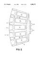
- FIG. 2is a top view of a slide frame for providing five sealed cavities above five different slides holding tissue samples.
- FIG. 3is a top view of a slide frame base.
- FIG. 4is a bottom view of a slide frame housing.
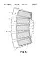
- FIG. 5is a top view of the slide frame housing with five microscope slides in their appropriate positions, showing the area to which heat is applied.
- FIG. 6is a cross-sectional view of a slide frame resting on the slide rotor.
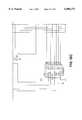
- FIG. 7is a schematic diagram of the heater and sensor wiring diagram, on the slide frame, and the interconnection with the temperature controller.
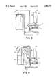
- FIG. 8is a side cross-sectional view of a cartridge pump dispensing mechanism in the liquid dispensing and removal station.
- FIG. 9is a side cross-sectional view of a bulk liquid dispensing station housed in the liquid dispensing and removal station.
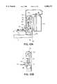
- FIGS. 10A and 10Bare side cross sectional views of a vacuum hose and transport mechanism for removing liquid reagent and wash fluids from slides contained on the slide rotor.
- FIG. 11Ais a side cross-sectional view of the aspiration head, showing its relationship to the glass slide in the slide frame.
- FIG. 11Bis a bottom end face view of the aspiration head.
- FIG. 12is a perspective view of a second embodiment of a slide stainer.
- FIG. 13is a perspective view of the liquid handling zone of the second embodiment of the slide stainer.
- FIGS. 14A and 14Bare side cross-sectional views of the liquid aspiration station of the second embodiment, with the aspiration head in the lowered (FIG. 14A) and raised (FIG. 14B) positions.
- FIG. 15is a schematic representation of the waste liquid pathways of the second embodiment.
- FIG. 16is a schematic representation of the bulk liquid dispense pathways of the second embodiment.
- FIG. 17is a schematic representation of the individual heaters on the slide rotor and the temperature control boards mounted on the slide rotor.
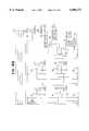
- FIGS. 18A-Dare a schematic diagram of the electronic circuitry of the temperature control board.
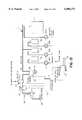
- FIG. 1shows a first embodiment 1 of the invention in perspective view.
- the first embodiment 1comprises a substantially circular assembly base 2, a slide rotor 3 rotatable on the assembly base 2, a reagent rotor 4 also rotatable on the assembly base, and a liquid dispensing and removal station 5.
- the slide rotor 3is driven to rotate by a servo motor (not shown) and carries ten slide frames 6 that are radially asserted into and detachable from it.
- a top view of single slide frame 6is shown in FIG. 2. Here, positions for five slides, each with a tissue sample, are shown in positions 7a-7e.
- the slide frame 6comprises a slide frame base 8 shown in FIG. 3.
- the slide frame base 8includes a heated area 9 which underlies each of the slide positions 7a-7e and incorporates resistive heating elements, not shown.
- the heating elementsare integrally formed in the slide frame base 8. Electricity for powering the heating elements is provided into the slide frame 6 from the assembly base 2 via first and second contacts 10.
- third and fourth contacts 11enable temperature sensing of the heated areas via thermocouples also integrally formed in the slide frame base 8. In practice, a sum of three connectors are required, since contacts 10 and 11 share the same ground connection. Therefore, one of the connectors 11 are left unused.
- FIG. 4is a top view of the slide frame housing 12 showing essentially a rigid plastic or metal frame 13 with five oval holes 14a-14e corresponding to each of the slide positions 7a-7e.
- a silicon rubber gasket 15is also provided under the frame 13.
- the slide frame housing 12, including the gasket 15 and frame 13is bolted onto the slide frame base 8 by two Allen bolts 16 to provide individual sealed cavities approximately 0.2-0.4 inches deep over each tissue sample slide placed at each of the slide positions 7a-7e.
- a total of 3 ml of reagents and/or rinsescan be placed in contact with the tissue samples of each one of the slides but a maximum quantity of 2 ml is preferable. Since the silicon gasket 15 is compressed by the frame 13 against the microscope slides (not shown), the cavities over each of the frame positions are mutually sealed from each other.
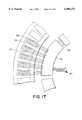
- FIG. 5is a top view of a slide frame base 8 with five microscope slides 17 in the positions denoted by 7a-7e in FIG. 3.
- the area of each slide 17 forming cavities, that are delimited by the silicone rubber gasket 15 and holes 14a-14eis indicated by an approximately rectangular line 18, marking the chamber wall.
- the area denoted by the hatched barsindicates the area of the slide frame base 8 that includes heating elements 9. The entire heated area (hatched bars) is raised to the same temperature, bringing the group of five slides to the same desired temperature.
- the portion of each slide 17 that is not above the heated areadoes not generally bear a biologic tissue specimen. Rather, it is used for labeling purposes.
- FIG. 6is a cross-sectional view of an assembled slide frame base 8 and housing 12, collectively referred to previously as the slide frame 6.
- the microscope slide 17is shown held in position, between the slide frame base 8 and housing 12.
- the slide frame 6is resting on the slide rotor 3.
- the electrical connection between the slide frame 6 and an edge connector 19is demonstrated.
- Four edge connectors per slide frame 6are provided (contacts 10 and 11 in FIGS. 2 and 3).
- the electrical connectionis fed from the edge connector 19 through the slide rotor via an insulated feed-through 20, to a terminal underneath the slide rotor 3.
- a wirethen connects the terminal to a source of power or control circuitry (not shown).
- FIG. 7is a schematic diagram, showing two out of the ten heater 91 and sensor 92 circuits that can be placed on the instrument slide rotor.
- the heateris represented schematically as a resistive element, and corresponds to the heated area (hatched bars) of FIG. 5.
- Contacts 10 and 11share a common ground connection, leaving one of the four connectors unused.
- Each of the circuitsfeeds into a temperature controller, represented schematically 21.
- Each slide framesends three wires to the temperature controller 21--a heater power conductor 22, a sensor conductor 23, and a ground connection 24.
- the temperature controller 21is mounted in a stationary position on the assembly base 2. Since the heaters and sensors are in frequent motion, they connect to the stationary temperature controller 21 via a service loop (not shown).
- the service loopcontains the wires from each of the edge connectors 19. Sufficient extra length is provided in the wires so that as the slide rotor rotates, the service loop travels around the slide rotor axis.
- the slide rotor 3does not turn more than one full revolution in either direction.
- the wires in the service loopare preferably bundled together with a wire tie, so that individual wires do not become entangled or caught underneath the slide rotor 3. Since there are three wires per circuit (wires 22-24), and there are ten slide frames 6 on the slide rotor 3, the service loop contains a minimum of thirty wires.
- the reagent rotor 4positioned above the slide rotor 3 is the reagent rotor 4.
- This reagent rotoris similarly adapted to rotate on the assembly base 2 and is driven by another servo motor (not shown) under computer control (not shown).
- the reagent rotor 4 and the slide rotor 3rotate independently of each other.
- the reagent rotor 4is adapted to carry up to ten cartridge frames 25. Each of these cartridge frames 25 are detachable from the reagent rotor 4 and can be selectively attached at any one of ten possible points of connection.
- Each cartridge frame 25is capable of carrying five of the cartridge pumps 46.
- the dispensing station 5comprises a soft hammer 26 for engaging a portion of the cartridge pumps 46.
- the cartridge pumps 46are constructed so as to dispense liquid when a portion of the cartridge pump 46, called the metering chamber 42 of the cartridge pump 46 is compressed. It is possible to dispense from any of a plurality of cartridge pumps by rotating the reagent rotor so as to align a desired cartridge pump 46 with the hammer 26. This provides the capability of dispensing precisely measured amounts of reagent to any slide positioned underneath the cartridge pump 46 adjacent to actuator 26.
- the mechanism for dispensing from the cartridge pumps 46is shown in greater detail in FIG. 8.
- the hammer 26is driven by a solenoid or linear stepping motor 43 that is mounted on a front wall 44, attached to the assembly base 2.
- a solenoid or linear stepping motor 43that is mounted on a front wall 44, attached to the assembly base 2.
- the hammeris shown compressing the metering chamber 42 portion of the cartridge pump. It is important to be able to adjust the speed of compression by the hammer 26 upon the metering chamber 42. Otherwise, too rapid a compression will cause an excessively forceful ejection of reagent from metering chamber 42, potentially damaging the tissue section underneath. Therefore, a linear stepping motor is preferred instead of a solenoid.
- the reciprocating hammer of the dispensing actuatorcould take the form of a cam, driven by a rotary motor, that engages the metering chamber 42 so that the rotation of the cam will compress the metering chamber.
- the cartridge pump 46is comprised of a liquid reservoir 45 and the metering chamber 42.
- the liquid reservoir 45 shown in this first embodiment 1is a syringe barrel.
- the metering chamber 42is comprised of a compressible elastomeric housing with a one-way inlet valve (not shown) and a one-way outlet valve (not shown), both valves aligned in a downwards direction of fluid flow.
- the dispensing station 5further includes a means to dispense liquids from a large bottle (FIG. 9).
- Bulk liquid bottles 27that can supply liquid into any one of the microscope slides 17 on any one of the slide frames 6 via rinse tubes 28.
- Each bulk liquid bottle 27is connected to its own rinse tube 28.
- the bulk liquid bottles 27are pressurized by a pump (not shown).
- the outflow tube (not shown) from each bulk liquid bottle 27passes through a valve 47 that regulates the flow of liquid from that bottle. By opening the valve for a defined period of time, under computer control (not shown), with a defined pressure within the bottle 27, a known quantity of liquid can be dispensed onto the slide 17.
- the liquids placed within the bottles 27are those that are used repeatedly among many different procedures, such as water, saline, and alcohol.
- the bulk liquid bottles 27are screwed into a female threaded cap 48 secured to the underside of the horizontal top wall 49 of the station frame.
- Compressed air from a compressor(not shown) is provided to each bulk liquid bottle 27 through a pressure regulator 50.
- Tubing from the pressure regulator 51transmits the compressed air to the inlet of the bulk liquid bottle 27.
- the pressure above the liquidenables the liquid to forced up through the dip tube 52 through the rinse hose 53 when a pinch valve 47 is opened.
- a pre-determined amount of liquidcan be dispensed through the rinse tube 28.
- the liquid dispensing and removal assembly 5further includes a liquid removal vacuum station, positioned adjacent to the rinse tubes 28 (not visible in FIG. 1).
- a liquid removal vacuum stationpositioned adjacent to the rinse tubes 28 (not visible in FIG. 1).
- the reagent rotorpositions the slide at the liquid removal vacuum station, shown in a side cross-sectional representation in FIGS. 10A and 10B.
- An external source of vacuum(not shown) is channeled through a trap flask 29, ultimately leading to a vacuum hose 30 that terminates in an aspiration head 31.
- the tubing connectionsare not shown in FIGS. 10A and 10B.
- the vacuum hose 30 and aspiration head 31are supported by a hose transport mechanism 54 that allows the aspiration head 31 to be extended down into a cavity of a slide frame 6 to remove liquid covering the tissue sample on the slide 17. As the aspiration head contacts the liquid, the liquid is sucked upwards into the tubing and collected into the trap flask 29.
- the vacuum hose transport mechanism 54comprises a motor 32.
- a reciprocating link 33is attached to a crank arm 34 so that the rotation of the motor 32 causes the reciprocating link 33 to traverse in a vertical direction.
- a bottom portion of the reciprocating link 33is connected to a lever 55 that is pivotally attached to the station frame.
- the other end of this leveris connected to a vacuum hose clamp 35 that is connected via pivot arms 36 to a plate 37 rigidly attached to the station frame.
- the net effect of these connectionsis that when the motor 32 is rotated, the slide arm 33 descends in a vertical direction.
- the lever 55is pivoted clockwise around its fulcrum causing the hose clamp 35 to pivot up and away on the two pivot arms 36 from the slide as shown in FIG. 10B.
- the motoris automatically turned off as the link 33 reaches its two extreme ends of movement by the contact of the electrical terminals 39 of the link to the contact plates 38 connected to the station frame.
- FIG. 11Ashows the aspiration head in a lowered position, in cross-section, within the cavity formed by the slide frame 6.
- the aspiration head 31comprises a hollow interior manifold 40 through which the vacuum force is transmitted across the entire lower surface of the aspiration head 31.
- Eight holes 41are drilled on the lower face of the aspiration head 31, through which the suction force is transmitted. Since the microscope slide 17 is planar, liquid on the slide surface spreads out in two dimensions. Therefore, in order to thoroughly remove liquid from all portions of the microscope slide 17, multiple aspiration sites are needed. We accomplish this with an aspiration head with a planar lower surface with multiple holes.
- Slidesare individually inserted and removed via a centrally located slide access door 63.
- the slides(not shown) are hidden from view by a circular platen 64 that is located above the slides and reagent rotor (not shown).
- Functions similar to the dispensing assembly (5 of FIG. 1) in the previous embodimentare accomplished in a somewhat similar liquid handling assembly (not shown) that is positioned in a liquid handling zone 65.
- the aspiration head 67comprises a hollow manifold 74 connected to a source of vacuum. Eight holes communicate between the bottom of the aspiration head 67 and the exterior, through which liquid is aspirated.
- vacuumis supplied to the aspiration head 67, and the head 67 is lowered adjacent to the slide, the liquid reagent on top of the slide is aspirated off and collected in a trap bottle 59 (shown schematically in FIG. 15).
- a trap bottle 59shown schematically in FIG. 15.
- the aspiration head 67is not in use, it is raised to the up position (FIG. 14B), allowing free rotation of the slide rotor 77.
- FIGS. 14A and 14Balso show the physical location of a heating element 78, represented as a resistive element inside a rectangular box with cross-hatched lines. Each slide rests directly on the heating element 78, so that heat is directly communicated to the microscope slide. A thermistor is incorporated into each heating element (not shown in FIGS. 14A and 14B). Each of forty-nine microscope slides 75 has its own heating element 78, so that the temperature of each slide 75 can be independently regulated. Power for the heating element 78 is supplied directly from a temperature control board 79 that is affixed to the underside of the slide rotor 77. Seven identical temperature control boards 79 are so mounted underneath the slide rotor 77, evenly spaced around the periphery. Each temperature control board supplies power for seven heating elements 78. The means by which this is accomplished is explained later, in reference to FIGS. 17 and 18A-D.
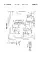
- FIG. 15A schematic diagram explaining how this is accomplished is shown in FIG. 15.
- Three different waste bottles 59are mounted on the instrument.
- Connections 70are also provided on the instrument for a large external trap bottle 71, typically of a ten or twenty liter capacity for aqueous waste.
- Valve 81is a three way valve. It can allow a direct connection between the vacuum pump 82 and the overflow trap 83, or between the pump and the ambient environment.
- valves 80A and 81are appropriately opened, the pump 82 turned on, and the aspirator head 67 lowered so as to aspirate liquid, the liquid will be directed upwards into the tubing, as represented by the arrow "fluid flow.” Liquid will then follow the only path available, and be collected into the external trap bottle 71.
- Valves 80B-80Dfunction similarly for their respective trap bottles 59.
- a small overflow trap bottle 83is also inserted into the line with its own fluid sensor 93. This provision is included so as to detect if any of the trap bottles 59, or external trap bottle 71 are overflowing with waste liquid. In that case, liquid would enter the overflow trap bottle and be detected by the fluid sensor. That information would be communicated to the controller 86, which would shut the system down and alert the instrument operator on the computer screen.
- the liquid handling zonealso includes an air-mix head 69.
- a schematic representation of the air flow into the air-mix head 69is shown in FIG. 15.
- the pumpgenerates a high velocity air stream that is channeled into the air-mix head 69.
- Air intake to the pumpis via the three way solenoid valve 81 (FIG. 15).
- the solenoid valve 81(FIG. 15) switches so as to channel air directly from the atmosphere to the pump (FIG. 15), bypassing the aspiration system and trap bottles 59 and 71.
- the high velocity air flowis focused onto the slide.
- the air-mix head 69travels back and forth along the length of the slide, pushed and pulled by a belt and pulley that is attached to a motor (not shown). The net effect of this system is to direct a curtain of air back and forth along the length of the slide, causing liquid to be mixed and spread along the surface of the microscope slide.
- the liquid handling zone 65includes a bulk liquid dispensing port 68 (FIG. 13).
- the function of the rinse tubes 28 of the first embodiment 1 (shown in FIG. 1)are all incorporated into a single bulk liquid dispensing port 68 in this preferred embodiment. Therefore, slides are positioned under the bulk liquid dispensing port 68 regardless of the bulk liquid bottle that the liquid is actually derived from.
- a schematic representation of the fluid pathways and control valvesis shown in FIG. 16.
- the bulk liquid bottles 57are each connected to a source of pressure, that is generated by a pump 85. The pressure is communicated to the bulk liquid bottles 57 via a pressure manifold 94.
- Solenoid valves 72a-72fare placed between the bulk liquid dispensing port 68 and each bulk liquid bottle 57. Liquid flows out the bulk liquid dispensing port 68 only when one or more of the valves 72a-72f are open.
- a pressure switch 84also communicates with the pressure manifold 94. It is capable of sensing the amount or pressure contained within the manifold 94. When it falls below a specified level, it communicates with the controller 86 causing activation of the pump 85. As the pump generates an increased amount of air pressure within the pressure manifold, the pressure switch resets, causing the pump to stop pumping. In this manner, a relatively constant pressure head is maintained within the pressure manifold 94.
- a dispense sensor 95is positioned underneath the bulk liquid dispensing port 68 to provide verification that liquid was dispensed when one of the solenoid valves 72a-72f were transiently opened.
- the dispense sensor 95comprises an optical sensor and an LED light source. When liquid is dispensed from the bulk liquid dispensing port 68, the liquid interrupts the light beam. The change in resistance across the sensor as a result of the decrement in light intensity is communicated to the controller 86.
- This second, preferred embodiment of the inventionincludes the capability to independently heat the forty-nine slides to different temperatures.
- a novel aspect of this embodimentis the method for independently regulating the amount of power that each of the forty-nine heaters receives.
- each heateralso incorporates a temperature sensor. Each of these sensors must communicate with the computer 86 in order to allow for appropriate temperature feedback and regulation.
- groups of up to five slideswere under a single, common temperature control mechanism. Each heating group had wires that directly connected with the temperature controller (FIG. 7). With three wires per group (power for heat, sensor feedback, and a shared ground) and ten groups of slides, at least thirty wires were contained in the service loop. If a similar system were used for forty-nine different heaters, as in this preferred embodiment, 147 wires would be required in the service loop. Such a bulky service loop would be problematic. Therefore, an alternative method is developed in this preferred embodiment.
- FIG. 17shows the relationship between each of the heating elements 78 mounted on the slide rotor 77, depicting the heating element 78 as a resistive element.
- a single sensor 87is adjacent to each heater.
- the combination of a single heating element 78 and sensor 87are so positioned so as to provide a location 88 for a single slide to be heated.
- the physical layout of this location 88is demonstrated in FIGS. 14A and 14B.
- Two wire leads from each heating element 78, and two wire leads from each sensor 87are connected directly to a temperature control board mounted on the slide rotor 77. Each temperature control board is capable of connecting to up to eight different heater and sensor pairs.
- this embodimentincorporates forty-nine slide positions, seven boards 79 are mounted to the underside of the slide rotor, each connecting to seven heater-sensor pairs. One heater-sensor position per temperature controller board 79 is not used. Also shown in FIG. 17 is the serial connection 89 of each of the seven temperature control boards, in a daisy-chain configuration, by six wires.
- the first temperature control boardis connected via a service loop 90 to the computer 86 (FIG. 16) which serves as the user interface and system controller.
- the service loopcontains only six wires.
- the computercommunicates that information to the temperature control board 79.
- the temperature control board 79directly regulates the amount of power flowing to each heater.
- the temperature control board 79 systemwas designed as a shift register.
- the machine's controlling microprocessorplaces bits of data one at a time on a transmission line, and toggles a clock line for each bit. This causes data to be sent through two shift register chips U1 and U2 on each control board, each taking eight bits. There are thus 16 ⁇ 7 or 112 bits to be sent out.
- the datacomes in on connector J9.1, and the clock line is J9.2.
- the shift registers used in this designare "double buffered," which means that the output data will not change until there is a transition on a second clock (R clock), which comes in on pin J9.3.
- J10is the "output" connector, which attaches via a short cable to J9 of the next board in line, for a total of seven boards.
- the other three pins of J9are used for power to run the electronics (J9.4), electronic ground (J9.5), and a common return line (J9.6) for temperature measurement function from the sensors.
- Component U4is an analog multiplexer which performs this function. Of the four digital bits which are received serially, one is used to enable U4, and the other three are used to select one of the component's eight channels (of which only seven are used). If pin four is driven low, U4 for that board 79 becomes active and places the voltage from one of the seven channels of that board on the shared output line at J9.6. Conversely, if pin four is pulled high, U4's output remains in a high impedance state and the output line is not driven. This allows data from a selected board 79 to be read, with the remaining boards 79 having no effect on the signal. Multiplexer U4 can only be enabled on one board 79 at a time; if more than one were turned on at a time, the signals would conflict and no useful data would be transmitted.
- Temperature sensingis accomplished by a voltage divider technique.
- a thermistor 87 and a fixed resistor(5.6 kilohms, R1-R8, contained in RS1) are placed in series across the 5 volt electronic power supply. When the thermistor is heated, its resistance drops and the voltage at the junction point with the 5.6 kilohm resistor will drop.
- the temperature control boards 79are small and inexpensive. Moreover, the heater boards are all identical. No "address" needs to be set for each board 79. Lastly, the service loop 90 is small in size.
- each temperature control board 79could be set up with a permanent "address" formed by adding jumper wires or traces cut on the board.
- the processorwould send out a packet of data which would contain an address segment and a data segment, and the data would be loaded to the board whose address matched the address sent out.
- This approachtakes less time to send data to a particular board, but the address comparison takes extra hardware. It also demands extra service loop wires to carry the data (if sent in parallel) or an extra shift register chip if the address is sent serially.
- each temperature control board 79could have its own microprocessor. They could all be connected via a serial data link to the main computer 86. This approach uses even fewer connecting wires than the present embodiment, but the cost of hardware is high. It also still implies an addressing scheme, meaning that the boards would not be identical. Also, code for the microprocessors would be required.
Landscapes
- Health & Medical Sciences (AREA)
- Life Sciences & Earth Sciences (AREA)
- Biochemistry (AREA)
- Immunology (AREA)
- Molecular Biology (AREA)
- Physics & Mathematics (AREA)
- Chemical & Material Sciences (AREA)
- Analytical Chemistry (AREA)
- Engineering & Computer Science (AREA)
- General Health & Medical Sciences (AREA)
- General Physics & Mathematics (AREA)
- Biomedical Technology (AREA)
- Pathology (AREA)
- Sampling And Sample Adjustment (AREA)
- Automatic Analysis And Handling Materials Therefor (AREA)
- Investigating Or Analysing Biological Materials (AREA)
- Sliding-Contact Bearings (AREA)
- Addition Polymer Or Copolymer, Post-Treatments, Or Chemical Modifications (AREA)
- External Artificial Organs (AREA)
Abstract
Description
Claims (8)
Priority Applications (13)
| Application Number | Priority Date | Filing Date | Title |
|---|---|---|---|
| US09/032,680US6096271A (en) | 1998-02-27 | 1998-02-27 | Random access slide stainer with liquid waste segregation |
| JP2000533731AJP4309577B2 (en) | 1998-02-27 | 1999-02-25 | Random access slide dyeing device with waste liquid separation function |
| AU27891/99AAU2789199A (en) | 1998-02-27 | 1999-02-25 | Random access slide stainer with liquid waste segregation |
| ES03078714TES2263912T3 (en) | 1998-02-27 | 1999-02-25 | POSITIONING EQUIPMENT OF SLIDES WITH RANDOM ACCESS TO THE SETTLEMENT OF LIQUID WASTE. |
| AT03078714TATE326691T1 (en) | 1998-02-27 | 1999-02-25 | COLOR DEVICE FOR MICROSCOPE SLIDES WITH RANDOM ACCESS AND SEPARATION OF LIQUID WASTE |
| DE69931408TDE69931408T2 (en) | 1998-02-27 | 1999-02-25 | Color scanner for microscope slides with "Random Access" and separation of liquid waste |
| EP03078714AEP1398613B1 (en) | 1998-02-27 | 1999-02-25 | Random access slide stainer with liquid waste segregation |
| CA002321739ACA2321739C (en) | 1998-02-27 | 1999-02-25 | Random access slide stainer with liquid waste segregation |
| ES99908460TES2212534T3 (en) | 1998-02-27 | 1999-02-25 | COLORING DEVICE OF ACCESSORIES SHEETS WITH SEPARATION OF LIQUID WASTE. |
| AT99908460TATE257245T1 (en) | 1998-02-27 | 1999-02-25 | STAINING DEVICE FOR MICROSCOPE SLIDES WITH RANDOM ACCESS AND SEPARATION OF LIQUID WASTE |
| EP99908460AEP1058826B1 (en) | 1998-02-27 | 1999-02-25 | Random access slide stainer with liquid waste segregation |
| PCT/US1999/004093WO1999044031A1 (en) | 1998-02-27 | 1999-02-25 | Random access slide stainer with liquid waste segregation |
| DE69913947TDE69913947T2 (en) | 1998-02-27 | 1999-02-25 | DYEING UNIT FOR MICROSCOPE SLAB WITH "RANDOM ACCESS" AND SEPARATION OF LIQUID WASTE |
Applications Claiming Priority (1)
| Application Number | Priority Date | Filing Date | Title |
|---|---|---|---|
| US09/032,680US6096271A (en) | 1998-02-27 | 1998-02-27 | Random access slide stainer with liquid waste segregation |
Publications (1)
| Publication Number | Publication Date |
|---|---|
| US6096271Atrue US6096271A (en) | 2000-08-01 |
Family
ID=21866251
Family Applications (1)
| Application Number | Title | Priority Date | Filing Date |
|---|---|---|---|
| US09/032,680Expired - LifetimeUS6096271A (en) | 1998-02-27 | 1998-02-27 | Random access slide stainer with liquid waste segregation |
Country Status (9)
| Country | Link |
|---|---|
| US (1) | US6096271A (en) |
| EP (2) | EP1398613B1 (en) |
| JP (1) | JP4309577B2 (en) |
| AT (2) | ATE326691T1 (en) |
| AU (1) | AU2789199A (en) |
| CA (1) | CA2321739C (en) |
| DE (2) | DE69913947T2 (en) |
| ES (2) | ES2212534T3 (en) |
| WO (1) | WO1999044031A1 (en) |
Cited By (71)
| Publication number | Priority date | Publication date | Assignee | Title |
|---|---|---|---|---|
| US6296809B1 (en)* | 1998-02-27 | 2001-10-02 | Ventana Medical Systems, Inc. | Automated molecular pathology apparatus having independent slide heaters |
| US20020094581A1 (en)* | 1998-02-24 | 2002-07-18 | Michael Cole | Method and apparatus for determining temperature of and controlling the evaporation of liquid samples |
| US6495106B1 (en)* | 1998-03-24 | 2002-12-17 | Biogenex Laboratories | Automated staining apparatus |
| US20030017075A1 (en)* | 1999-07-08 | 2003-01-23 | Lee Angros | In situ heat induced antigen recovery and staining method |
| US6582962B1 (en) | 1998-02-27 | 2003-06-24 | Ventana Medical Systems, Inc. | Automated molecular pathology apparatus having independent slide heaters |
| US6585936B1 (en)* | 2002-06-28 | 2003-07-01 | Preyas Sarabhai Shah | Slide stainer with controlled fluid flow |
| WO2003065030A1 (en)* | 2002-01-25 | 2003-08-07 | Irm, Llc | Fluid handling methods and systems |
| US20030179445A1 (en)* | 1999-10-29 | 2003-09-25 | Garrick Maenle | Cytological imaging systems and methods |
| US6673620B1 (en)* | 1999-04-20 | 2004-01-06 | Cytologix Corporation | Fluid exchange in a chamber on a microscope slide |
| US20040009098A1 (en)* | 2002-06-14 | 2004-01-15 | Torre-Bueno Jose De La | Automated slide staining apparatus |
| US20040191128A1 (en)* | 1992-05-11 | 2004-09-30 | Cytologix Corporation | Slide stainer with heating |
| US20040221477A1 (en)* | 2002-09-12 | 2004-11-11 | Lg Electronics Inc. | Structure of motor shaft in clothes dryer |
| US20040241050A1 (en)* | 1998-02-27 | 2004-12-02 | Cytologix Corporation | Random access slide stainer with independent slide heating regulation |
| US20050201901A1 (en)* | 2004-01-25 | 2005-09-15 | Fluidigm Corp. | Crystal forming devices and systems and methods for using the same |
| US20060105359A1 (en)* | 2003-05-14 | 2006-05-18 | Dakocytomation Denmark A/S | Method and apparatus for automated pre-treatment and processing of biological samples |
| US20060134793A1 (en)* | 2004-07-23 | 2006-06-22 | Dako Denmark A/S | Method and apparatus for automated pre-treatment and processing of biological samples |
| US20060148063A1 (en)* | 2003-05-14 | 2006-07-06 | Fauzzi John A | Method and apparatus for automated pre-treatment and processing of biological samples |
| US20060178776A1 (en)* | 2003-12-15 | 2006-08-10 | Feingold Gordon A | Systems and methods for the automated pre-treatment and processing of biological samples |
| USD531736S1 (en) | 2005-05-04 | 2006-11-07 | Abbott Laboratories | Reagent carrier for use in an automated analyzer |
| USD532524S1 (en) | 2005-05-04 | 2006-11-21 | Abbott Laboratories | Reagent carrier for use in an automated analyzer |
| US20060263248A1 (en)* | 2005-05-04 | 2006-11-23 | Gomm Cordell K | Reagent and sample handling device for automatic testing system |
| US20060275889A1 (en)* | 1999-07-08 | 2006-12-07 | Lee Angros | In situ heat induced antigen recovery and staining apparatus and method |
| US20060275861A1 (en)* | 1999-07-08 | 2006-12-07 | Lee Angros | In situ heat induced antigen recovery and staining apparatus and method |
| US20060281116A1 (en)* | 1999-07-08 | 2006-12-14 | Lee Angros | In situ heat induced antigen recovery and staining apparatus and method |
| USD533947S1 (en) | 2005-05-04 | 2006-12-19 | Abbott Laboratories | Reagent carrier for use in an automated analyzer |
| USD534280S1 (en) | 2005-05-04 | 2006-12-26 | Abbott Laboratories | Reagent carrier for use in an automated analyzer |
| US20070092431A1 (en)* | 2005-06-28 | 2007-04-26 | Resasco Daniel E | Methods for growing and harvesting carbon nanotubes |
| US20070122797A1 (en)* | 2001-11-13 | 2007-05-31 | De La Torre-Bueno Jose | System for tracking biological samples |
| US7270785B1 (en) | 2001-11-02 | 2007-09-18 | Ventana Medical Systems, Inc. | Automated molecular pathology apparatus having fixed slide platforms |
| US7303725B2 (en) | 2002-04-15 | 2007-12-04 | Ventana Medical Systems, Inc. | Automated high volume slide staining system |
| WO2008060347A1 (en)* | 2006-11-17 | 2008-05-22 | Sru Biosystems, Inc. | Simultaneous aspirator and dispenser for multiwell plates and similar devices |
| US7378055B2 (en) | 2002-04-26 | 2008-05-27 | Ventana Medical Systems, Inc. | Automated molecular pathology apparatus having fixed slide platforms |
| US20080154543A1 (en)* | 2006-12-22 | 2008-06-26 | Ganesh Rajagopal | Liquid waste management system |
| US7396508B1 (en)* | 2000-07-12 | 2008-07-08 | Ventana Medical Systems, Inc. | Automated molecular pathology apparatus having independent slide heaters |
| US7400983B2 (en) | 2002-12-20 | 2008-07-15 | Dako Denmark A/S | Information notification sample processing system and methods of biological slide processing |
| US20080194034A1 (en)* | 2005-04-21 | 2008-08-14 | Celerus Diagnostics, Inc. | Method And Apparatus For Automated Rapid Immunohistochemistry |
| US7425306B1 (en) | 2001-09-11 | 2008-09-16 | Ventana Medical Systems, Inc. | Slide heater |
| US7468161B2 (en) | 2002-04-15 | 2008-12-23 | Ventana Medical Systems, Inc. | Automated high volume slide processing system |
| US20080318129A1 (en)* | 2005-01-25 | 2008-12-25 | Gene Lewis | Fuel Cell Cathodes |
| US7501283B2 (en) | 2003-08-11 | 2009-03-10 | Sakura Finetek U.S.A., Inc. | Fluid dispensing apparatus |
| US20090253592A1 (en)* | 2003-12-23 | 2009-10-08 | Kram Brian H | Method and apparatus for treating a biological sample with a liquid reagent |
| US20090253163A1 (en)* | 2008-04-02 | 2009-10-08 | General Electric Company | Iterative staining of biological samples |
| US20090325309A1 (en)* | 2004-03-02 | 2009-12-31 | Favuzzi John A | Reagent Delivery System, Dispensing Device and Container for a Biological Staining Apparatus |
| US20100028978A1 (en)* | 2005-05-24 | 2010-02-04 | Angros Lee H | In situ heat induced antigen recovery and staining apparatus and method |
| US7718435B1 (en)* | 1992-05-11 | 2010-05-18 | Dako Denmark A/S | Automated slide stainer with slide housing |
| US20100144018A1 (en)* | 2008-12-10 | 2010-06-10 | Rushabh Instruments, Llc | Automated slide staining apparatus |
| US7744817B2 (en) | 2003-08-11 | 2010-06-29 | Sakura Finetek U.S.A., Inc. | Manifold assembly |
| US7767152B2 (en) | 2003-08-11 | 2010-08-03 | Sakura Finetek U.S.A., Inc. | Reagent container and slide reaction retaining tray, and method of operation |
| US20110091962A1 (en)* | 2008-01-31 | 2011-04-21 | Richard Carsillo | Automated Stainer Having Stain Level Detection |
| US20110150725A1 (en)* | 2005-05-24 | 2011-06-23 | Lee Angros | In situ heat induced antigen recovery and staining apparatus and method |
| RU2439572C2 (en)* | 2005-05-24 | 2012-01-10 | Ли Х. АНГРОС | APPARATUS FOR CAUSED BY THERMAL PROCESSING RESTORATION OF ANTIGEN in situ AND STAINING AND METHOD |
| WO2012064873A1 (en) | 2010-11-10 | 2012-05-18 | Constitution Medical, Inc. | Automated systems and methods for preparing biological specimens for examination |
| WO2012174535A1 (en) | 2011-06-17 | 2012-12-20 | Constitution Medical, Inc. | Solutions for histoprocessing of biological samples |
| US8459509B2 (en) | 2006-05-25 | 2013-06-11 | Sakura Finetek U.S.A., Inc. | Fluid dispensing apparatus |
| US8501434B2 (en) | 2010-10-06 | 2013-08-06 | Biocare, LLC | Method for processing non-liquid biological samples with dynamic application of a processing liquid |
| US8580568B2 (en) | 2011-09-21 | 2013-11-12 | Sakura Finetek U.S.A., Inc. | Traceability for automated staining system |
| US8645167B2 (en) | 2008-02-29 | 2014-02-04 | Dakocytomation Denmark A/S | Systems and methods for tracking and providing workflow information |
| US8752732B2 (en) | 2011-02-01 | 2014-06-17 | Sakura Finetek U.S.A., Inc. | Fluid dispensing system |
| US8932543B2 (en) | 2011-09-21 | 2015-01-13 | Sakura Finetek U.S.A., Inc. | Automated staining system and reaction chamber |
| US9091621B2 (en) | 2013-04-05 | 2015-07-28 | GGB Company | Multiple slide processing apparatus |
| US9518899B2 (en) | 2003-08-11 | 2016-12-13 | Sakura Finetek U.S.A., Inc. | Automated reagent dispensing system and method of operation |
| US9891147B2 (en) | 2013-04-05 | 2018-02-13 | Roche Diagnostics Hematology, Inc. | Automated systems and methods for preparing biological specimens for examination |
| CN107860632A (en)* | 2017-11-07 | 2018-03-30 | 山西大学 | A kind of drosophila wing bud active immunity group makeup is put |
| US9945763B1 (en) | 2011-02-18 | 2018-04-17 | Biocare Medical, Llc | Methods and systems for immunohistochemistry heat retrieval of biological samples |
| WO2018118985A1 (en) | 2016-12-19 | 2018-06-28 | Ventana Medical Systems, Inc. | Passive, gravity-driven system for treatment of an effluent in a diagnostic system |
| CN108663255A (en)* | 2018-08-01 | 2018-10-16 | 希肯医疗技术(苏州)有限公司 | Full-automatic immunohistochemical staining machine |
| US10184862B2 (en) | 2008-11-12 | 2019-01-22 | Ventana Medical Systems, Inc. | Methods and apparatuses for heating slides carrying specimens |
| CN110057649A (en)* | 2019-05-21 | 2019-07-26 | 广西农业职业技术学院 | Use for laboratory slide staining device |
| US10634590B2 (en) | 2014-03-11 | 2020-04-28 | Emd Millipore Corporation | IHC, tissue slide fluid exchange disposable and system |
| US10794805B2 (en) | 2013-12-13 | 2020-10-06 | Ventana Medical Systems, Inc. | Automated histological processing of biological specimens and associated technology |
| US11249095B2 (en) | 2002-04-15 | 2022-02-15 | Ventana Medical Systems, Inc. | Automated high volume slide processing system |
Families Citing this family (3)
| Publication number | Priority date | Publication date | Assignee | Title |
|---|---|---|---|---|
| SE9904349D0 (en)* | 1999-11-30 | 1999-11-30 | Active Biotech Ab | Novel device |
| JP2004317420A (en)* | 2003-04-18 | 2004-11-11 | Hitachi Software Eng Co Ltd | Measuring instrument using capillary |
| CN111693352B (en)* | 2020-06-18 | 2023-04-07 | 遵义医科大学 | Dyeing equipment |
Citations (26)
| Publication number | Priority date | Publication date | Assignee | Title |
|---|---|---|---|---|
| US3853092A (en)* | 1973-10-25 | 1974-12-10 | Corning Glass Works | Apparatus for nutating and staining a microscope slide |
| US4034700A (en)* | 1976-05-25 | 1977-07-12 | Honeywell Inc. | Slide preparation station |
| US4043292A (en)* | 1975-07-21 | 1977-08-23 | Corning Glass Works | Microscope slide staining apparatus having temperature control |
| US4092952A (en)* | 1977-08-19 | 1978-06-06 | Wilkie Ronald N | Automatic slide stainer |
| US4358470A (en)* | 1978-02-10 | 1982-11-09 | Lkb-Produkter Ab | Process and apparatus for the treatment of samples with a succession of liquids |
| US4543236A (en)* | 1979-04-14 | 1985-09-24 | Gise Hardo F Von | Incubating apparatus for selective and exact treatment of histological preparations |
| EP0201780A1 (en)* | 1985-04-27 | 1986-11-20 | Jan Hastka | Apparatus and method for cytological and histological examinations of sample slides |
| US4731335A (en)* | 1985-09-13 | 1988-03-15 | Fisher Scientific Company | Method for treating thin samples on a surface employing capillary flow |
| US4847208A (en)* | 1987-07-29 | 1989-07-11 | Bogen Steven A | Apparatus for immunohistochemical staining and method of rinsing a plurality of slides |
| US4858155A (en)* | 1985-12-24 | 1989-08-15 | Beckman Instruments, Inc. | Reaction temperature control system |
| US4865986A (en)* | 1988-10-06 | 1989-09-12 | Coy Corporation | Temperature control apparatus |
| US4933146A (en)* | 1986-07-11 | 1990-06-12 | Beckman Instruments, Inc. | Temperature control apparatus for automated clinical analyzer |
| US4985206A (en)* | 1987-09-30 | 1991-01-15 | Shandon Scientific Limited | Tissue processing apparatus |
| WO1993009486A1 (en)* | 1991-11-05 | 1993-05-13 | Hybaid Limited | Reaction temperature control device |
| US5231029A (en)* | 1989-08-23 | 1993-07-27 | Royal Postgraduate Medical School | Apparatus for the in situ hybridization of slide-mounted cell samples |
| US5246665A (en)* | 1991-06-03 | 1993-09-21 | Abbott Laboratories | Heat and air flow control for assay carrier |
| US5316452A (en)* | 1992-05-11 | 1994-05-31 | Gilbert Corporation | Dispensing assembly with interchangeable cartridge pumps |
| US5419279A (en)* | 1992-09-29 | 1995-05-30 | Hoffmann-La Roche Inc. | Apparatus for depositing and staining cytological material on a microscope slide |
| US5425918A (en)* | 1990-07-18 | 1995-06-20 | Australian Biomedical Corporation | Apparatus for automatic tissue staining for immunohistochemistry |
| US5439649A (en)* | 1993-09-29 | 1995-08-08 | Biogenex Laboratories | Automated staining apparatus |
| US5475610A (en)* | 1990-11-29 | 1995-12-12 | The Perkin-Elmer Corporation | Thermal cycler for automatic performance of the polymerase chain reaction with close temperature control |
| US5559032A (en)* | 1990-06-29 | 1996-09-24 | Pomeroy; Patrick C. | Method and apparatus for post-transfer assaying of material on solid support |
| US5595707A (en)* | 1990-03-02 | 1997-01-21 | Ventana Medical Systems, Inc. | Automated biological reaction apparatus |
| US5601141A (en)* | 1992-10-13 | 1997-02-11 | Intelligent Automation Systems, Inc. | High throughput thermal cycler |
| US5645114A (en)* | 1992-05-11 | 1997-07-08 | Cytologix Corporation | Dispensing assembly with interchangeable cartridge pumps |
| US5773293A (en)* | 1992-01-27 | 1998-06-30 | Icos Corporation | Anti-ICAM-4 antibodies and hybridomas |
Family Cites Families (2)
| Publication number | Priority date | Publication date | Assignee | Title |
|---|---|---|---|---|
| GB2234348B (en)* | 1986-12-04 | 1991-07-31 | Univ Leicester | Apparatus for reactions on a specimen with liquids |
| AUPN038995A0 (en)* | 1995-01-05 | 1995-01-27 | Australian Biomedical Corporation Limited | Method and apparatus for human or animal cell sample treatment |
- 1998
- 1998-02-27USUS09/032,680patent/US6096271A/ennot_activeExpired - Lifetime
- 1999
- 1999-02-25DEDE69913947Tpatent/DE69913947T2/ennot_activeExpired - Lifetime
- 1999-02-25EPEP03078714Apatent/EP1398613B1/ennot_activeExpired - Lifetime
- 1999-02-25CACA002321739Apatent/CA2321739C/ennot_activeExpired - Lifetime
- 1999-02-25EPEP99908460Apatent/EP1058826B1/ennot_activeExpired - Lifetime
- 1999-02-25JPJP2000533731Apatent/JP4309577B2/ennot_activeExpired - Fee Related
- 1999-02-25ATAT03078714Tpatent/ATE326691T1/ennot_activeIP Right Cessation
- 1999-02-25ESES99908460Tpatent/ES2212534T3/ennot_activeExpired - Lifetime
- 1999-02-25ATAT99908460Tpatent/ATE257245T1/ennot_activeIP Right Cessation
- 1999-02-25WOPCT/US1999/004093patent/WO1999044031A1/enactiveIP Right Grant
- 1999-02-25AUAU27891/99Apatent/AU2789199A/ennot_activeAbandoned
- 1999-02-25ESES03078714Tpatent/ES2263912T3/ennot_activeExpired - Lifetime
- 1999-02-25DEDE69931408Tpatent/DE69931408T2/ennot_activeExpired - Lifetime
Patent Citations (28)
| Publication number | Priority date | Publication date | Assignee | Title |
|---|---|---|---|---|
| US3853092A (en)* | 1973-10-25 | 1974-12-10 | Corning Glass Works | Apparatus for nutating and staining a microscope slide |
| US4043292A (en)* | 1975-07-21 | 1977-08-23 | Corning Glass Works | Microscope slide staining apparatus having temperature control |
| US4034700A (en)* | 1976-05-25 | 1977-07-12 | Honeywell Inc. | Slide preparation station |
| US4092952A (en)* | 1977-08-19 | 1978-06-06 | Wilkie Ronald N | Automatic slide stainer |
| US4358470A (en)* | 1978-02-10 | 1982-11-09 | Lkb-Produkter Ab | Process and apparatus for the treatment of samples with a succession of liquids |
| US4543236A (en)* | 1979-04-14 | 1985-09-24 | Gise Hardo F Von | Incubating apparatus for selective and exact treatment of histological preparations |
| EP0201780A1 (en)* | 1985-04-27 | 1986-11-20 | Jan Hastka | Apparatus and method for cytological and histological examinations of sample slides |
| US4731335A (en)* | 1985-09-13 | 1988-03-15 | Fisher Scientific Company | Method for treating thin samples on a surface employing capillary flow |
| US4731335B1 (en)* | 1985-09-13 | 1991-07-09 | Fisher Scientific Co | |
| US4858155A (en)* | 1985-12-24 | 1989-08-15 | Beckman Instruments, Inc. | Reaction temperature control system |
| US4933146A (en)* | 1986-07-11 | 1990-06-12 | Beckman Instruments, Inc. | Temperature control apparatus for automated clinical analyzer |
| US5073504A (en)* | 1987-07-29 | 1991-12-17 | Bogen Steven A | Apparatus and method for immunohistochemical staining |
| US4847208A (en)* | 1987-07-29 | 1989-07-11 | Bogen Steven A | Apparatus for immunohistochemical staining and method of rinsing a plurality of slides |
| US4985206A (en)* | 1987-09-30 | 1991-01-15 | Shandon Scientific Limited | Tissue processing apparatus |
| US4865986A (en)* | 1988-10-06 | 1989-09-12 | Coy Corporation | Temperature control apparatus |
| US5231029A (en)* | 1989-08-23 | 1993-07-27 | Royal Postgraduate Medical School | Apparatus for the in situ hybridization of slide-mounted cell samples |
| US5595707A (en)* | 1990-03-02 | 1997-01-21 | Ventana Medical Systems, Inc. | Automated biological reaction apparatus |
| US5559032A (en)* | 1990-06-29 | 1996-09-24 | Pomeroy; Patrick C. | Method and apparatus for post-transfer assaying of material on solid support |
| US5425918A (en)* | 1990-07-18 | 1995-06-20 | Australian Biomedical Corporation | Apparatus for automatic tissue staining for immunohistochemistry |
| US5475610A (en)* | 1990-11-29 | 1995-12-12 | The Perkin-Elmer Corporation | Thermal cycler for automatic performance of the polymerase chain reaction with close temperature control |
| US5246665A (en)* | 1991-06-03 | 1993-09-21 | Abbott Laboratories | Heat and air flow control for assay carrier |
| WO1993009486A1 (en)* | 1991-11-05 | 1993-05-13 | Hybaid Limited | Reaction temperature control device |
| US5773293A (en)* | 1992-01-27 | 1998-06-30 | Icos Corporation | Anti-ICAM-4 antibodies and hybridomas |
| US5316452A (en)* | 1992-05-11 | 1994-05-31 | Gilbert Corporation | Dispensing assembly with interchangeable cartridge pumps |
| US5645114A (en)* | 1992-05-11 | 1997-07-08 | Cytologix Corporation | Dispensing assembly with interchangeable cartridge pumps |
| US5419279A (en)* | 1992-09-29 | 1995-05-30 | Hoffmann-La Roche Inc. | Apparatus for depositing and staining cytological material on a microscope slide |
| US5601141A (en)* | 1992-10-13 | 1997-02-11 | Intelligent Automation Systems, Inc. | High throughput thermal cycler |
| US5439649A (en)* | 1993-09-29 | 1995-08-08 | Biogenex Laboratories | Automated staining apparatus |
Non-Patent Citations (6)
| Title |
|---|
| MaWhinney, W.H.B., et al., "Automated Immunochemistry," J. Clin. Pathol., 43(7):591-596 (1990). |
| MaWhinney, W.H.B., et al., Automated Immunochemistry, J. Clin. Pathol. , 43(7):591 596 (1990).* |
| Stark, E., et al., "An Automated Device for Immunocytochemistry," Journal of Immunological Methods, 107:89-92 (1988). |
| Stark, E., et al., An Automated Device for Immunocytochemistry, Journal of Immunological Methods , 107:89 92 (1988).* |
| Stross, W.P., et al., "Automation of APAAP Immunocytochemical Technique," J. Clin. Pathol., 42:106-112 (1989). |
| Stross, W.P., et al., Automation of APAAP Immunocytochemical Technique, J. Clin. Pathol. , 42:106 112 (1989).* |
Cited By (240)
| Publication number | Priority date | Publication date | Assignee | Title |
|---|---|---|---|---|
| US20040191128A1 (en)* | 1992-05-11 | 2004-09-30 | Cytologix Corporation | Slide stainer with heating |
| US7718435B1 (en)* | 1992-05-11 | 2010-05-18 | Dako Denmark A/S | Automated slide stainer with slide housing |
| US7498175B2 (en)* | 1998-02-24 | 2009-03-03 | Genevac Limited | Method and apparatus for determining temperature of and controlling the evaporation of liquid samples |
| US20020094581A1 (en)* | 1998-02-24 | 2002-07-18 | Michael Cole | Method and apparatus for determining temperature of and controlling the evaporation of liquid samples |
| US6878342B2 (en)* | 1998-02-24 | 2005-04-12 | Michael Cole | Apparatus for determining temperance of and controlling the evaporation of liquid samples |
| US20070281364A1 (en)* | 1998-02-27 | 2007-12-06 | Bogen Steven A | Random access slide stainer with independent slide heating regulation |
| US6582962B1 (en) | 1998-02-27 | 2003-06-24 | Ventana Medical Systems, Inc. | Automated molecular pathology apparatus having independent slide heaters |
| US7553672B2 (en) | 1998-02-27 | 2009-06-30 | Dako Denmark A/S | Random access slide stainer with independent slide heating regulation |
| US7217392B2 (en)* | 1998-02-27 | 2007-05-15 | Cytologix Corporation | Random access slide stainer with independent slide heating regulation |
| US20040052685A1 (en)* | 1998-02-27 | 2004-03-18 | Ventana Medical Systems, Inc. | Automated molecular pathology apparatus having independent slide heaters |
| US6296809B1 (en)* | 1998-02-27 | 2001-10-02 | Ventana Medical Systems, Inc. | Automated molecular pathology apparatus having independent slide heaters |
| US20040241050A1 (en)* | 1998-02-27 | 2004-12-02 | Cytologix Corporation | Random access slide stainer with independent slide heating regulation |
| US6495106B1 (en)* | 1998-03-24 | 2002-12-17 | Biogenex Laboratories | Automated staining apparatus |
| US20080056954A1 (en)* | 1999-04-20 | 2008-03-06 | Loeffler Herbert H | Fluid exchange in a chamber on a microscope slide |
| US7318913B2 (en) | 1999-04-20 | 2008-01-15 | Cytologix Corporation | Fluid exchange in a chamber on a microscope slide |
| US6673620B1 (en)* | 1999-04-20 | 2004-01-06 | Cytologix Corporation | Fluid exchange in a chamber on a microscope slide |
| US20040086428A1 (en)* | 1999-04-20 | 2004-05-06 | Cytologix Corporation | Fluid exchange in a chamber on a microscope slide |
| US8173068B2 (en) | 1999-04-20 | 2012-05-08 | Dako Denmark A/S | Fluid exchange in a chamber on a microscope slide |
| US10281375B2 (en) | 1999-07-08 | 2019-05-07 | Lee H. Angros | In situ heat induced antigen recovery and staining method |
| US8313694B2 (en) | 1999-07-08 | 2012-11-20 | Lee Angros | In situ heat induced antigen recovery and staining apparatus and method |
| US20050054079A1 (en)* | 1999-07-08 | 2005-03-10 | Lee Angros | In situ heat induced antigen recovery and staining apparatus and method |
| US20050053526A1 (en)* | 1999-07-08 | 2005-03-10 | Lee Angros | In situ heat induced antigen recovery and staining apparatus and method |
| US8092742B2 (en) | 1999-07-08 | 2012-01-10 | Lee Angros | In situ heat induced antigen recovery and staining apparatus and method |
| US8071023B2 (en) | 1999-07-08 | 2011-12-06 | Lee Angros | In situ heat induced antigen recovery and staining apparatus and method |
| US20030017075A1 (en)* | 1999-07-08 | 2003-01-23 | Lee Angros | In situ heat induced antigen recovery and staining method |
| US8052927B2 (en) | 1999-07-08 | 2011-11-08 | Lee Angros | In situ heat induced antigen recovery and staining method |
| US8354058B2 (en) | 1999-07-08 | 2013-01-15 | Lee Angros | In situ heat induced antigen recovery and staining apparatus and method |
| US8007721B2 (en) | 1999-07-08 | 2011-08-30 | Lee Angros | In Situ heat induced antigen recovery and staining apparatus and method |
| US8007720B2 (en) | 1999-07-08 | 2011-08-30 | Lee Angros | In situ heat induced antigen recovery and staining apparatus and method |
| US8574494B2 (en) | 1999-07-08 | 2013-11-05 | Lee Angros | In situ heat induced antigen recovery and staining method |
| US7951612B2 (en) | 1999-07-08 | 2011-05-31 | Lee H. Angros | In situ heat induced antigen recovery and staining apparatus and method |
| US10416052B2 (en) | 1999-07-08 | 2019-09-17 | Lee H. Angros | In situ heat induced antigen recovery and staining apparatus and method |
| US20060275889A1 (en)* | 1999-07-08 | 2006-12-07 | Lee Angros | In situ heat induced antigen recovery and staining apparatus and method |
| US20060275861A1 (en)* | 1999-07-08 | 2006-12-07 | Lee Angros | In situ heat induced antigen recovery and staining apparatus and method |
| US20060281116A1 (en)* | 1999-07-08 | 2006-12-14 | Lee Angros | In situ heat induced antigen recovery and staining apparatus and method |
| US7897106B2 (en) | 1999-07-08 | 2011-03-01 | Lee Angros | Situ heat induced antigen recovery and staining apparatus and method |
| US9464974B2 (en) | 1999-07-08 | 2016-10-11 | Lee H. Angros | In situ heat induced antigen recovery and staining apparatus and method |
| US20090270599A1 (en)* | 1999-07-08 | 2009-10-29 | Lee Angros | In situ heat induced antigen recovery and staining method |
| US8696988B2 (en) | 1999-07-08 | 2014-04-15 | Lee H. Angros | In situ heat induced antigen recovery and staining apparatus and method |
| US9976941B2 (en) | 1999-07-08 | 2018-05-22 | Lee H. Angros | In situ heat induced antigen recovery and staining method |
| US8329100B2 (en) | 1999-07-08 | 2012-12-11 | Lee Angros | In situ heat induced antigen recovery and staining apparatus and method |
| US8298485B2 (en) | 1999-07-08 | 2012-10-30 | Lee H. Angros | In situ heat induced antigen recovery and staining apparatus and method |
| US7476362B2 (en) | 1999-07-08 | 2009-01-13 | Lee Angros | In situ heat induced antigen recovery and staining apparatus and method |
| US7622077B2 (en) | 1999-07-08 | 2009-11-24 | Lee Angros | In situ heat induced antigen recovery and staining apparatus and method |
| US7250301B2 (en) | 1999-07-08 | 2007-07-31 | Lee Angros | In situ heat induced antigen recovery and staining method |
| US9176033B2 (en) | 1999-07-08 | 2015-11-03 | Lee H. Angros | In situ heat induced antigen recovery and staining method |
| US20070231889A1 (en)* | 1999-07-08 | 2007-10-04 | Lee Angros | In situ heat induced antigen recovery and staining method |
| US20050054080A1 (en)* | 1999-07-08 | 2005-03-10 | Lee Angros | In situ heat induced antigen recovery and staining apparatus and method |
| US7632461B2 (en) | 1999-07-08 | 2009-12-15 | Lee Angros | In situ heat induced antigen recovery and staining apparatus and method |
| US20100009429A1 (en)* | 1999-07-08 | 2010-01-14 | Angros Lee H | In situ heat induced antigen recovery and staining apparatus and method |
| US9606034B2 (en) | 1999-07-08 | 2017-03-28 | Lee H. Angros | In situ heat induced antigen recovery and staining method |
| US9772266B2 (en) | 1999-07-08 | 2017-09-26 | Lee H. Angros | In situ heat induced antigen recovery and staining method |
| US20100068096A1 (en)* | 1999-07-08 | 2010-03-18 | Lee Angros | In situ heat induced antigen recovery and staining apparatus and method |
| US7468836B2 (en) | 1999-10-29 | 2008-12-23 | Cytyc Corporation | Cytological imaging systems and methods |
| US20080013168A1 (en)* | 1999-10-29 | 2008-01-17 | Cytyc Corporation | Cytological imaging systems and methods |
| US20080018994A1 (en)* | 1999-10-29 | 2008-01-24 | Cytyc Corporation | Cytological imaging systems and methods |
| US20080013812A1 (en)* | 1999-10-29 | 2008-01-17 | Cytyc Corporation | Cytological imaging systems and methods |
| US7667890B2 (en) | 1999-10-29 | 2010-02-23 | Cytyc Corporation | Cytological imaging systems and methods |
| US20060077541A1 (en)* | 1999-10-29 | 2006-04-13 | Cytyc Corporation | Cytological imaging systems and methods |
| US20100128944A1 (en)* | 1999-10-29 | 2010-05-27 | Cytyc Corporation | Cytological imaging systems and methods |
| US20030179445A1 (en)* | 1999-10-29 | 2003-09-25 | Garrick Maenle | Cytological imaging systems and methods |
| US7446935B2 (en) | 1999-10-29 | 2008-11-04 | Cytyc Corporation | Cytological imaging systems and methods |
| US7369304B2 (en) | 1999-10-29 | 2008-05-06 | Cytyc Corporation | Cytological autofocusing imaging systems and methods |
| US7396508B1 (en)* | 2000-07-12 | 2008-07-08 | Ventana Medical Systems, Inc. | Automated molecular pathology apparatus having independent slide heaters |
| US7425306B1 (en) | 2001-09-11 | 2008-09-16 | Ventana Medical Systems, Inc. | Slide heater |
| US7404927B2 (en) | 2001-11-02 | 2008-07-29 | Ventana Medical Systems, Inc. | Automated molecular pathology apparatus having fixed slide platforms |
| US7270785B1 (en) | 2001-11-02 | 2007-09-18 | Ventana Medical Systems, Inc. | Automated molecular pathology apparatus having fixed slide platforms |
| US9633176B2 (en) | 2001-11-13 | 2017-04-25 | Dako Denmark A/S | Method for tracking and imaging biological samples |
| US9117024B2 (en) | 2001-11-13 | 2015-08-25 | Dako Denmark A/S | System for tracking biological samples |
| US20070124084A1 (en)* | 2001-11-13 | 2007-05-31 | Torre-Bueno Jose D L | Method for tracking and imaging biological samples |
| US20070122797A1 (en)* | 2001-11-13 | 2007-05-31 | De La Torre-Bueno Jose | System for tracking biological samples |
| US8676509B2 (en) | 2001-11-13 | 2014-03-18 | Dako Denmark A/S | System for tracking biological samples |
| US9659153B2 (en) | 2001-11-13 | 2017-05-23 | Dako Denmark A/S | System for tracking biological samples |
| US20030175157A1 (en)* | 2002-01-25 | 2003-09-18 | Irm, Llc | Fluid handling methods and systems |
| WO2003065030A1 (en)* | 2002-01-25 | 2003-08-07 | Irm, Llc | Fluid handling methods and systems |
| US7468161B2 (en) | 2002-04-15 | 2008-12-23 | Ventana Medical Systems, Inc. | Automated high volume slide processing system |
| US8663991B2 (en) | 2002-04-15 | 2014-03-04 | Ventana Medical Systems, Inc. | Automated high volume slide processing system |
| US7303725B2 (en) | 2002-04-15 | 2007-12-04 | Ventana Medical Systems, Inc. | Automated high volume slide staining system |
| US10302665B2 (en) | 2002-04-15 | 2019-05-28 | Ventana Medical Systems, Inc. | Automated high volume slide processing system |
| US11092611B2 (en) | 2002-04-15 | 2021-08-17 | Ventana Medical Systems, Inc. | Automated high volume slide processing system |
| US11249095B2 (en) | 2002-04-15 | 2022-02-15 | Ventana Medical Systems, Inc. | Automated high volume slide processing system |
| US9528918B2 (en) | 2002-04-15 | 2016-12-27 | Ventana Medical Systems, Inc. | Automated high volume slide processing system |
| US8048373B2 (en) | 2002-04-15 | 2011-11-01 | Ventana Medical Systems, Inc. | Automated high volume slide staining system |
| US7378055B2 (en) | 2002-04-26 | 2008-05-27 | Ventana Medical Systems, Inc. | Automated molecular pathology apparatus having fixed slide platforms |
| US20050282292A1 (en)* | 2002-06-14 | 2005-12-22 | Chroma Vision Medical Systems, Inc. | Automated slide staining apparatus |
| US6800249B2 (en) | 2002-06-14 | 2004-10-05 | Chromavision Medical Systems, Inc. | Automated slide staining apparatus |
| US20040009098A1 (en)* | 2002-06-14 | 2004-01-15 | Torre-Bueno Jose De La | Automated slide staining apparatus |
| US7226788B2 (en) | 2002-06-14 | 2007-06-05 | Carl Zeiss Microimaging Ais, Inc. | Automated slide staining apparatus |
| WO2004003570A1 (en)* | 2002-06-28 | 2004-01-08 | Preyas Sarabhai Shah | Slide stainer with controlled fluid flow |
| US6585936B1 (en)* | 2002-06-28 | 2003-07-01 | Preyas Sarabhai Shah | Slide stainer with controlled fluid flow |
| US20040221477A1 (en)* | 2002-09-12 | 2004-11-11 | Lg Electronics Inc. | Structure of motor shaft in clothes dryer |
| US7661202B2 (en)* | 2002-09-12 | 2010-02-16 | Lg Electronics Inc. | Structure of motor shaft in clothes dryer |
| US8673642B2 (en) | 2002-12-20 | 2014-03-18 | Dako Denmark A/S | Enhanced scheduling sample processing system and methods of biological slide processing |
| US9229016B2 (en) | 2002-12-20 | 2016-01-05 | Dako Denmark A/S | Information notification sample processing system and methods of biological slide processing |
| US20100017030A1 (en)* | 2002-12-20 | 2010-01-21 | Dako Denmark A/S | Systems and methods for the automated pre-treatment and processing of biological samples |
| US7648678B2 (en) | 2002-12-20 | 2010-01-19 | Dako Denmark A/S | Method and system for pretreatment of tissue slides |
| US8788217B2 (en) | 2002-12-20 | 2014-07-22 | Dako Denmark A/S | Information notification sample processing system and methods of biological slide processing |
| US8784735B2 (en) | 2002-12-20 | 2014-07-22 | Dako Denmark A/S | Apparatus for automated processing biological samples |
| US9778273B2 (en) | 2002-12-20 | 2017-10-03 | Dako Denmark A/S | Isolated communication sample processing system and methods of biological slide processing |
| US7400983B2 (en) | 2002-12-20 | 2008-07-15 | Dako Denmark A/S | Information notification sample processing system and methods of biological slide processing |
| US9599630B2 (en) | 2002-12-20 | 2017-03-21 | Dako Denmark A/S | Method and apparatus for automatic staining of tissue samples |
| US8257968B2 (en) | 2002-12-20 | 2012-09-04 | Dako Denmark A/S | Method and apparatus for automatic staining of tissue samples |
| US8216512B2 (en) | 2002-12-20 | 2012-07-10 | Dako Denmark A/S | Apparatus for automated processing biological samples |
| US7758809B2 (en) | 2002-12-20 | 2010-07-20 | Dako Cytomation Denmark A/S | Method and system for pretreatment of tissue slides |
| US8969086B2 (en) | 2002-12-20 | 2015-03-03 | Dako Denmark A/S | Enhanced scheduling sample processing system and methods of biological slide processing |
| US8529836B2 (en) | 2002-12-20 | 2013-09-10 | Dako Denmark A/S | Apparatus for automated processing biological samples |
| US10156580B2 (en) | 2002-12-20 | 2018-12-18 | Dako Denmark A/S | Information notification sample processing system and methods of biological slide processing |
| US8386195B2 (en) | 2002-12-20 | 2013-02-26 | Dako Denmark A/S | Information notification sample processing system and methods of biological slide processing |
| US9182324B2 (en) | 2002-12-20 | 2015-11-10 | Dako Denmark A/S | Systems and methods for the automated pre-treatment and processing of biological samples |
| US8394635B2 (en) | 2002-12-20 | 2013-03-12 | Dako Denmark A/S | Enhanced scheduling sample processing system and methods of biological slide processing |
| US7960178B2 (en) | 2002-12-20 | 2011-06-14 | Dako Denmark A/S | Enhanced scheduling sample processing system and methods of biological slide processing |
| US8298815B2 (en) | 2002-12-20 | 2012-10-30 | Dako Denmark A/S | Systems and methods of sample processing and temperature control |
| US8663978B2 (en) | 2002-12-20 | 2014-03-04 | Dako Denmark A/S | Method and apparatus for automatic staining of tissue samples |
| US7937228B2 (en) | 2002-12-20 | 2011-05-03 | Dako Denmark A/S | Information notification sample processing system and methods of biological slide processing |
| US20060105359A1 (en)* | 2003-05-14 | 2006-05-18 | Dakocytomation Denmark A/S | Method and apparatus for automated pre-treatment and processing of biological samples |
| US7875245B2 (en) | 2003-05-14 | 2011-01-25 | Dako Denmark A/S | Method and apparatus for automated pre-treatment and processing of biological samples |
| US7850912B2 (en) | 2003-05-14 | 2010-12-14 | Dako Denmark A/S | Method and apparatus for automated pre-treatment and processing of biological samples |
| US20060148063A1 (en)* | 2003-05-14 | 2006-07-06 | Fauzzi John A | Method and apparatus for automated pre-treatment and processing of biological samples |
| US7767152B2 (en) | 2003-08-11 | 2010-08-03 | Sakura Finetek U.S.A., Inc. | Reagent container and slide reaction retaining tray, and method of operation |
| US7501283B2 (en) | 2003-08-11 | 2009-03-10 | Sakura Finetek U.S.A., Inc. | Fluid dispensing apparatus |
| US7744817B2 (en) | 2003-08-11 | 2010-06-29 | Sakura Finetek U.S.A., Inc. | Manifold assembly |
| US9518899B2 (en) | 2003-08-11 | 2016-12-13 | Sakura Finetek U.S.A., Inc. | Automated reagent dispensing system and method of operation |
| US20070010912A1 (en)* | 2003-12-08 | 2007-01-11 | Feingold Gordon A | Systems and methods for the automated pre-treatment and processing of biological samples |
| US7603201B2 (en) | 2003-12-08 | 2009-10-13 | Dako Denmark A/S | Systems and methods for the automated pre-treatment and processing of biological samples |
| US7584019B2 (en) | 2003-12-15 | 2009-09-01 | Dako Denmark A/S | Systems and methods for the automated pre-treatment and processing of biological samples |
| US20060178776A1 (en)* | 2003-12-15 | 2006-08-10 | Feingold Gordon A | Systems and methods for the automated pre-treatment and processing of biological samples |
| US20090253592A1 (en)* | 2003-12-23 | 2009-10-08 | Kram Brian H | Method and apparatus for treating a biological sample with a liquid reagent |
| US7615371B2 (en) | 2003-12-23 | 2009-11-10 | Ventana Medical Systems, Inc. | Method and apparatus for treating a biological sample with a liquid reagent |
| US20050201901A1 (en)* | 2004-01-25 | 2005-09-15 | Fluidigm Corp. | Crystal forming devices and systems and methods for using the same |
| US8105553B2 (en)* | 2004-01-25 | 2012-01-31 | Fluidigm Corporation | Crystal forming devices and systems and methods for using the same |
| AU2010214783B2 (en)* | 2004-01-25 | 2011-07-21 | Fluidigm Corporation | Crystal forming devices and systems and methods for making and using the same |
| US20090325309A1 (en)* | 2004-03-02 | 2009-12-31 | Favuzzi John A | Reagent Delivery System, Dispensing Device and Container for a Biological Staining Apparatus |
| US8486714B2 (en) | 2004-03-02 | 2013-07-16 | Dako Denmark A/S | Reagent delivery system, dispensing device and container for a biological staining apparatus |
| US9164013B2 (en) | 2004-03-02 | 2015-10-20 | Dako Denmark A/S | Reagent delivery system, dispensing device and container for a biological staining apparatus |
| US7867443B2 (en) | 2004-07-23 | 2011-01-11 | Dako Denmark A/S | Method and apparatus for automated pre-treatment and processing of biological samples |
| US20060134793A1 (en)* | 2004-07-23 | 2006-06-22 | Dako Denmark A/S | Method and apparatus for automated pre-treatment and processing of biological samples |
| US20080318129A1 (en)* | 2005-01-25 | 2008-12-25 | Gene Lewis | Fuel Cell Cathodes |
| US8034610B2 (en) | 2005-04-21 | 2011-10-11 | Celerus Diagnostics, Inc. | Parallel processing fluidic method and apparatus for automated rapid immunohistochemistry |
| US8058010B2 (en) | 2005-04-21 | 2011-11-15 | Celerus Diagnostics, Inc. | Enhanced fluidic method and apparatus for automated rapid immunohistochemistry |
| US8178350B2 (en) | 2005-04-21 | 2012-05-15 | Celerus Diagnostics, Inc. | Method and apparatus for automated rapid immunohistochemistry |
| US20080194034A1 (en)* | 2005-04-21 | 2008-08-14 | Celerus Diagnostics, Inc. | Method And Apparatus For Automated Rapid Immunohistochemistry |
| US20080213804A1 (en)* | 2005-04-21 | 2008-09-04 | Celerus Diagnostics, Inc. | Parallel Processing Fluidic Method and Apparatus for Automated Rapid Immunohistochemistry |
| US20080286753A1 (en)* | 2005-04-21 | 2008-11-20 | Celerus Diagnostics, Inc. | Wicking Cassette Method and Apparatus for Automated Rapid Immunohistochemistry |
| US20090004691A1 (en)* | 2005-04-21 | 2009-01-01 | Celerus Diagnostics, Inc. | Enhanced Fluidic Method and Apparatus for Automated Rapid Immunohistochemistry |
| US7838283B2 (en) | 2005-04-21 | 2010-11-23 | Celerus Diagnostics, Inc. | Wicking cassette method and apparatus for automated rapid immunohistochemistry |
| US11815518B2 (en) | 2005-04-27 | 2023-11-14 | Ventana Medical Systems, Inc. | Automated high volume slide processing system |
| US10900982B2 (en) | 2005-04-27 | 2021-01-26 | Ventana Medical Systems, Inc. | Automated high volume slide processing system |
| USD533947S1 (en) | 2005-05-04 | 2006-12-19 | Abbott Laboratories | Reagent carrier for use in an automated analyzer |
| US7628954B2 (en) | 2005-05-04 | 2009-12-08 | Abbott Laboratories, Inc. | Reagent and sample handling device for automatic testing system |
| USD532524S1 (en) | 2005-05-04 | 2006-11-21 | Abbott Laboratories | Reagent carrier for use in an automated analyzer |
| USD531736S1 (en) | 2005-05-04 | 2006-11-07 | Abbott Laboratories | Reagent carrier for use in an automated analyzer |
| USD534280S1 (en) | 2005-05-04 | 2006-12-26 | Abbott Laboratories | Reagent carrier for use in an automated analyzer |
| US10191072B2 (en) | 2005-05-04 | 2019-01-29 | Abbott Laboratories | Reagent and sample handling device for automatic testing system |
| US20060263248A1 (en)* | 2005-05-04 | 2006-11-23 | Gomm Cordell K | Reagent and sample handling device for automatic testing system |
| US9057714B2 (en) | 2005-05-04 | 2015-06-16 | Abbott Laboratories | Reagent and sample handling device for automatic testing system |
| US20110229978A1 (en)* | 2005-05-24 | 2011-09-22 | Lee Angros | In situ heat induced antigen recovery and staining apparatus and method |
| US8377377B2 (en) | 2005-05-24 | 2013-02-19 | Lee H. Angros | In situ heat induced antigen recovery and staining apparatus and method |
| RU2439572C2 (en)* | 2005-05-24 | 2012-01-10 | Ли Х. АНГРОС | APPARATUS FOR CAUSED BY THERMAL PROCESSING RESTORATION OF ANTIGEN in situ AND STAINING AND METHOD |
| US9354145B2 (en) | 2005-05-24 | 2016-05-31 | Lee Angros | In situ heat induced antigen recovery and staining apparatus and method |
| US8361388B2 (en) | 2005-05-24 | 2013-01-29 | Lee H. Angros | In situ heat induced antigen recovery and staining apparatus and method |
| US20110150725A1 (en)* | 2005-05-24 | 2011-06-23 | Lee Angros | In situ heat induced antigen recovery and staining apparatus and method |
| US10697868B2 (en) | 2005-05-24 | 2020-06-30 | Lee H. Angros | In situ heat induced antigen recovery and staining apparatus and method |
| US8541244B2 (en) | 2005-05-24 | 2013-09-24 | Lee H. Angros | In situ heat induced antigen recovery and staining apparatus and method |
| US9719895B2 (en) | 2005-05-24 | 2017-08-01 | Lee H. Angros | In situ heat induced antigen recovery and staining apparatus and method |
| US20100028978A1 (en)* | 2005-05-24 | 2010-02-04 | Angros Lee H | In situ heat induced antigen recovery and staining apparatus and method |
| US11585737B2 (en) | 2005-05-24 | 2023-02-21 | Lee H. Angros | In situ heat induced antigen recovery and staining apparatus and method |
| US7842387B2 (en) | 2005-06-28 | 2010-11-30 | The Board Of Regents Of The University Of Oklahoma | Methods for growing and harvesting carbon nanotubes |
| US20070092431A1 (en)* | 2005-06-28 | 2007-04-26 | Resasco Daniel E | Methods for growing and harvesting carbon nanotubes |
| US20070010911A1 (en)* | 2005-07-07 | 2007-01-11 | Feingold Gordon A | Systems and methods for the automated pre-treatment and processing of biological samples |
| US7593787B2 (en) | 2005-07-07 | 2009-09-22 | Dako Denmark A/S | Systems and methods for the automated pre-treatment and processing of biological samples |
| US9914124B2 (en) | 2006-05-25 | 2018-03-13 | Sakura Finetek U.S.A., Inc. | Fluid dispensing apparatus |
| US8459509B2 (en) | 2006-05-25 | 2013-06-11 | Sakura Finetek U.S.A., Inc. | Fluid dispensing apparatus |
| WO2008060347A1 (en)* | 2006-11-17 | 2008-05-22 | Sru Biosystems, Inc. | Simultaneous aspirator and dispenser for multiwell plates and similar devices |
| JP2009532704A (en)* | 2006-11-17 | 2009-09-10 | エス アール ユー バイオシステムズ,インコーポレイテッド | Aspirator / distributor for multiwell plates and similar devices |
| US8061220B2 (en) | 2006-11-17 | 2011-11-22 | Sru Biosystems, Inc. | Simultaneous aspirator and dispenser for multiwell plates and similar devices |
| US20090282931A1 (en)* | 2006-11-17 | 2009-11-19 | Sru Biosystems, Inc. | Simultaneous aspirator and dispenser for multiwell plates and similar devices |
| US7628085B2 (en) | 2006-11-17 | 2009-12-08 | Sru Biosystems, Inc. | Simultaneous aspirator and dispenser for multiwell plates and similar devices |
| US20100043571A1 (en)* | 2006-11-17 | 2010-02-25 | Sru Biosystems, Inc. | Simultaneous aspirator and dispenser for multiwell plates and similar devices |
| AU2007302639B2 (en)* | 2006-11-17 | 2010-01-14 | Sru Biosystems, Inc. | Simultaneous aspirator and dispenser for multiwell plates and similar devices |
| US20080115567A1 (en)* | 2006-11-17 | 2008-05-22 | Sru Biosystems, Inc. | Simultaneous aspirator and dispenser for multiwell plates and similar devices |
| US7832291B2 (en) | 2006-11-17 | 2010-11-16 | Sru Biosystems, Inc. | Simultaneous aspirator and dispenser for multiwell plates and similar devices |
| US8449839B2 (en) | 2006-12-22 | 2013-05-28 | Abbott Laboratories | Liquid waste management system |
| US20080154543A1 (en)* | 2006-12-22 | 2008-06-26 | Ganesh Rajagopal | Liquid waste management system |
| US20110091962A1 (en)* | 2008-01-31 | 2011-04-21 | Richard Carsillo | Automated Stainer Having Stain Level Detection |
| US9767425B2 (en) | 2008-02-29 | 2017-09-19 | Dako Denmark A/S | Systems and methods for tracking and providing workflow information |
| US8645167B2 (en) | 2008-02-29 | 2014-02-04 | Dakocytomation Denmark A/S | Systems and methods for tracking and providing workflow information |
| US10832199B2 (en) | 2008-02-29 | 2020-11-10 | Agilent Technologies, Inc. | Systems and methods for tracking and providing workflow information |
| US20090253163A1 (en)* | 2008-04-02 | 2009-10-08 | General Electric Company | Iterative staining of biological samples |
| US20100068757A1 (en)* | 2008-08-29 | 2010-03-18 | Angros Lee H | In situ heat induced antigen recovery and staining apparatus and method |
| US8486335B2 (en) | 2008-08-29 | 2013-07-16 | Lee H. Angros | In situ heat induced antigen recovery and staining apparatus and method |
| US10386275B2 (en) | 2008-08-29 | 2019-08-20 | Lee H. Angros | In situ heat induced antigen recovery and staining apparatus and method |
| US12372442B2 (en) | 2008-08-29 | 2025-07-29 | Lee H. Angros | In situ heat induced antigen recovery and staining apparatus and method |
| US9267868B2 (en) | 2008-08-29 | 2016-02-23 | Lee H. Angros | In Situ heat induced antigen recovery and staining apparatus and method |
| US11668629B2 (en) | 2008-08-29 | 2023-06-06 | Lee H. Angros | In situ heat induced antigen recovery and staining apparatus and method |
| US10768079B2 (en) | 2008-08-29 | 2020-09-08 | Lee H. Angros | In situ heat induced antigen recovery and staining apparatus and method |
| US10048177B2 (en) | 2008-08-29 | 2018-08-14 | Lee H. Angros | In situ heat induced antigen recovery and staining apparatus and method |
| US9766165B2 (en) | 2008-08-29 | 2017-09-19 | Lee H. Angros | In situ heat induced antigen recovery and staining apparatus and method |
| US10281376B2 (en) | 2008-08-29 | 2019-05-07 | Lee H. Angros | In situ heat induced antigen recovery and staining apparatus and method |
| US11493410B2 (en) | 2008-11-12 | 2022-11-08 | Ventana Medical Systems, Inc. | Methods for heating microscope slides carrying specimens |
| US10520403B2 (en) | 2008-11-12 | 2019-12-31 | Ventana Medical Systems, Inc. | Apparatuses for heating microscope slides carrying specimens |
| US10184862B2 (en) | 2008-11-12 | 2019-01-22 | Ventana Medical Systems, Inc. | Methods and apparatuses for heating slides carrying specimens |
| US10429280B2 (en) | 2008-11-12 | 2019-10-01 | Ventana Medical Systems, Inc. | Methods for heating microscope slides carrying specimens |
| US8158061B2 (en) | 2008-12-10 | 2012-04-17 | Rushabh Instruments, Llc | Automated slide staining apparatus |
| US20100144018A1 (en)* | 2008-12-10 | 2010-06-10 | Rushabh Instruments, Llc | Automated slide staining apparatus |
| US8501434B2 (en) | 2010-10-06 | 2013-08-06 | Biocare, LLC | Method for processing non-liquid biological samples with dynamic application of a processing liquid |
| US9442049B2 (en) | 2010-10-06 | 2016-09-13 | Biocare Medical, Llc | Efficient processing systems and methods for biological samples |
| US8454908B2 (en) | 2010-11-10 | 2013-06-04 | Constitution Medical, Inc. | Automated systems and methods for preparing biological specimens for examination |
| US9116087B2 (en) | 2010-11-10 | 2015-08-25 | Roche Diagnostics Hematology, Inc. | Automated systems and methods for preparing biological specimens for examination |
| WO2012064873A1 (en) | 2010-11-10 | 2012-05-18 | Constitution Medical, Inc. | Automated systems and methods for preparing biological specimens for examination |
| EP3467469A1 (en) | 2010-11-10 | 2019-04-10 | Roche Diagnostics Hematology, Inc. | Automated apparatus for preparing biological specimens for examination |
| US10175153B2 (en) | 2010-11-10 | 2019-01-08 | Roche Diagnostics Hematology, Inc. | Automated systems and methods for preparing biological specimens for examination |
| US10775282B2 (en) | 2010-11-10 | 2020-09-15 | Roche Diagnostics Hematology, Inc | Automated systems and methods for preparing biological specimens for examination |
| US9016526B2 (en) | 2011-02-01 | 2015-04-28 | Sakura Finetek U.S.A., Inc. | Fluid dispensing system |
| US8752732B2 (en) | 2011-02-01 | 2014-06-17 | Sakura Finetek U.S.A., Inc. | Fluid dispensing system |
| US9945763B1 (en) | 2011-02-18 | 2018-04-17 | Biocare Medical, Llc | Methods and systems for immunohistochemistry heat retrieval of biological samples |
| EP4086605A1 (en) | 2011-06-17 | 2022-11-09 | Roche Diagnostics Hematology, Inc. | Solution and method for histoprocessing of biological samples |
| WO2012174535A1 (en) | 2011-06-17 | 2012-12-20 | Constitution Medical, Inc. | Solutions for histoprocessing of biological samples |
| US9005980B2 (en) | 2011-09-21 | 2015-04-14 | Sakura Finetek U.S.A., Inc. | Traceability for automated staining system |
| US8580568B2 (en) | 2011-09-21 | 2013-11-12 | Sakura Finetek U.S.A., Inc. | Traceability for automated staining system |
| US10295444B2 (en) | 2011-09-21 | 2019-05-21 | Sakura Finetek U.S.A., Inc. | Automated staining system and reaction chamber |
| US12281970B2 (en) | 2011-09-21 | 2025-04-22 | Sakura Finetek U.S.A., Inc. | Automated staining system and reaction chamber |
| US8932543B2 (en) | 2011-09-21 | 2015-01-13 | Sakura Finetek U.S.A., Inc. | Automated staining system and reaction chamber |
| US9891147B2 (en) | 2013-04-05 | 2018-02-13 | Roche Diagnostics Hematology, Inc. | Automated systems and methods for preparing biological specimens for examination |
| US9091621B2 (en) | 2013-04-05 | 2015-07-28 | GGB Company | Multiple slide processing apparatus |
| US12117381B2 (en) | 2013-04-05 | 2024-10-15 | Roche Diagnostics Hematology, Inc. | Automated systems and methods for preparing biological specimens for examination |
| EP3693722A1 (en) | 2013-04-05 | 2020-08-12 | Roche Diagnostics Hematology, Inc. | Automated systems and methods for preparing biological specimens for examination |
| US9435720B2 (en) | 2013-04-05 | 2016-09-06 | Hardy Diagnostics | Multiple slide processing apparatus |
| US10794805B2 (en) | 2013-12-13 | 2020-10-06 | Ventana Medical Systems, Inc. | Automated histological processing of biological specimens and associated technology |
| US12181389B2 (en) | 2013-12-13 | 2024-12-31 | Ventana Medical Systems, Inc. | Automated histological processing of biological specimens and associated technology |
| US11614387B2 (en) | 2013-12-13 | 2023-03-28 | Ventana Medical Systems, Inc. | Automated histological processing of biological specimens and associated technology |
| US10634590B2 (en) | 2014-03-11 | 2020-04-28 | Emd Millipore Corporation | IHC, tissue slide fluid exchange disposable and system |
| WO2018118985A1 (en) | 2016-12-19 | 2018-06-28 | Ventana Medical Systems, Inc. | Passive, gravity-driven system for treatment of an effluent in a diagnostic system |
| US11970406B2 (en) | 2016-12-19 | 2024-04-30 | Ventana Medical Systems, Inc. | Passive, gravity-driven system for treatment of an effluent in a diagnostic system |
| US11401177B2 (en) | 2016-12-19 | 2022-08-02 | Ventana Medical Systems, Inc. | Passive, gravity-driven system for treatment of an effluent in a diagnostic system |
| US12252417B2 (en) | 2016-12-19 | 2025-03-18 | Ventana Medical Systems, Inc. | Passive, gravity-driven system for treatment of an effluent in a diagnostic system |
| CN107860632A (en)* | 2017-11-07 | 2018-03-30 | 山西大学 | A kind of drosophila wing bud active immunity group makeup is put |
| CN107860632B (en)* | 2017-11-07 | 2020-01-03 | 山西大学 | Automatic immunohistochemical device of fruit bat wing bud |
| CN108663255B (en)* | 2018-08-01 | 2023-11-21 | 希肯医疗技术(苏州)有限公司 | Full-automatic immunohistochemical dyeing machine |
| CN108663255A (en)* | 2018-08-01 | 2018-10-16 | 希肯医疗技术(苏州)有限公司 | Full-automatic immunohistochemical staining machine |
| CN110057649A (en)* | 2019-05-21 | 2019-07-26 | 广西农业职业技术学院 | Use for laboratory slide staining device |
Also Published As
| Publication number | Publication date |
|---|---|
| DE69931408D1 (en) | 2006-06-22 |
| EP1398613B1 (en) | 2006-05-17 |
| WO1999044031A1 (en) | 1999-09-02 |
| EP1058826B1 (en) | 2004-01-02 |
| ATE257245T1 (en) | 2004-01-15 |
| DE69913947D1 (en) | 2004-02-05 |
| AU2789199A (en) | 1999-09-15 |
| ES2263912T3 (en) | 2006-12-16 |
| EP1058826A1 (en) | 2000-12-13 |
| DE69913947T2 (en) | 2004-12-09 |
| CA2321739C (en) | 2008-12-16 |
| EP1398613A3 (en) | 2004-03-31 |
| DE69931408T2 (en) | 2007-04-19 |
| JP4309577B2 (en) | 2009-08-05 |
| CA2321739A1 (en) | 1999-09-02 |
| JP2002505419A (en) | 2002-02-19 |
| EP1398613A2 (en) | 2004-03-17 |
| ES2212534T3 (en) | 2004-07-16 |
| ATE326691T1 (en) | 2006-06-15 |
Similar Documents
| Publication | Publication Date | Title |
|---|---|---|
| US6096271A (en) | Random access slide stainer with liquid waste segregation | |
| CA2321823C (en) | Random access slide stainer with independent slide heating regulation | |
| US6027691A (en) | Automatic chemistry analyzer | |
| US8303915B2 (en) | Thin film apparatus and method | |
| US20040191128A1 (en) | Slide stainer with heating | |
| CN100413594C (en) | Biological material processing device | |
| JP5889448B2 (en) | Improvements in dyeing equipment and methods | |
| CA2435789A1 (en) | System and cartridge for processing a biological sample | |
| US20210031181A1 (en) | Cartridge and device for chemical or biological assays | |
| WO2001068259A1 (en) | Automated specimen processing apparatus with fluid detection | |
| CN111693354A (en) | Frozen slice immunohistochemical staining machine and method | |
| CN214066682U (en) | Frozen section immunohistochemical dyeing machine | |
| JPH028746A (en) | Analyzer | |
| JP2005291729A (en) | Biochemical analyzer |
Legal Events
| Date | Code | Title | Description |
|---|---|---|---|
| AS | Assignment | Owner name:CYTOLOGIX CORPORATION, MASSACHUSETTS Free format text:ASSIGNMENT OF ASSIGNORS INTEREST;ASSIGNORS:BOGEN, STEVEN A.;LOEFFLER, HERBERT H.;REEL/FRAME:009058/0001 Effective date:19980319 | |
| AS | Assignment | Owner name:TRANSAMERICA BUSINESS CREDIT CORPORATION, ILLINOIS Free format text:SECURITY INTEREST;ASSIGNOR:CYTOLOGIX CORPORATION;REEL/FRAME:010648/0012 Effective date:19991227 | |
| STCF | Information on status: patent grant | Free format text:PATENTED CASE | |
| AS | Assignment | Owner name:OXFORD BIOSCIENCE PARTNERS III L.P., MASSACHUSETTS Free format text:SECURITY AGREEMENT;ASSIGNOR:CYTOLOGIX CORPORATION;REEL/FRAME:013000/0685 Effective date:20020530 Owner name:OXFORD BIOSCIENCE PARTNERS III L.P.,MASSACHUSETTS Free format text:SECURITY AGREEMENT;ASSIGNOR:CYTOLOGIX CORPORATION;REEL/FRAME:013000/0685 Effective date:20020530 | |
| AS | Assignment | Owner name:CYTOLOGIX CORPORATION, MASSACHUSETTS Free format text:TERMINATION OF SECURITY AGREEMENT;ASSIGNOR:TRANSAMERICA TECHNOLOGY FINANCE CORPORATION SUCCESSOR IN INTEREST TO TRANSAMERICA BUSINESS CREDIT CORPORATION;REEL/FRAME:013193/0960 Effective date:20020805 | |
| AS | Assignment | Owner name:CYTOLOGIX CORPORATION, MASSACHUSETTS Free format text:TERMINATION OF SECURITY AGREEMENT;ASSIGNOR:OXFORD BIOSCIENCE PARTNERS III L.P.;REEL/FRAME:013211/0579 Effective date:20020816 Owner name:CYTOLOGIX CORPORATION,MASSACHUSETTS Free format text:TERMINATION OF SECURITY AGREEMENT;ASSIGNOR:OXFORD BIOSCIENCE PARTNERS III L.P.;REEL/FRAME:013211/0579 Effective date:20020816 | |
| FEPP | Fee payment procedure | Free format text:PAT HOLDER NO LONGER CLAIMS SMALL ENTITY STATUS, ENTITY STATUS SET TO UNDISCOUNTED (ORIGINAL EVENT CODE: STOL); ENTITY STATUS OF PATENT OWNER: LARGE ENTITY | |
| REFU | Refund | Free format text:REFUND - SURCHARGE, PETITION TO ACCEPT PYMT AFTER EXP, UNINTENTIONAL (ORIGINAL EVENT CODE: R2551); ENTITY STATUS OF PATENT OWNER: LARGE ENTITY | |
| FPAY | Fee payment | Year of fee payment:4 | |
| FPAY | Fee payment | Year of fee payment:8 | |
| FEPP | Fee payment procedure | Free format text:PAYOR NUMBER ASSIGNED (ORIGINAL EVENT CODE: ASPN); ENTITY STATUS OF PATENT OWNER: LARGE ENTITY Free format text:PAYER NUMBER DE-ASSIGNED (ORIGINAL EVENT CODE: RMPN); ENTITY STATUS OF PATENT OWNER: LARGE ENTITY | |
| AS | Assignment | Owner name:DAKO DENMARK A/S, DENMARK Free format text:ASSIGNMENT OF ASSIGNORS INTEREST;ASSIGNOR:CYTOLOGIX CORPORATION;REEL/FRAME:020762/0402 Effective date:20080407 Owner name:DAKO DENMARK A/S,DENMARK Free format text:ASSIGNMENT OF ASSIGNORS INTEREST;ASSIGNOR:CYTOLOGIX CORPORATION;REEL/FRAME:020762/0402 Effective date:20080407 | |
| FPAY | Fee payment | Year of fee payment:12 |