US6096081A - Diaphysial cortical dowel - Google Patents
Diaphysial cortical dowelDownload PDFInfo
- Publication number
- US6096081A US6096081AUS09/101,903US10190398AUS6096081AUS 6096081 AUS6096081 AUS 6096081AUS 10190398 AUS10190398 AUS 10190398AUS 6096081 AUS6096081 AUS 6096081A
- Authority
- US
- United States
- Prior art keywords
- dowel
- cortical
- bone
- graft
- canal
- Prior art date
- Legal status (The legal status is an assumption and is not a legal conclusion. Google has not performed a legal analysis and makes no representation as to the accuracy of the status listed.)
- Expired - Lifetime
Links
Images


Classifications
- A—HUMAN NECESSITIES
- A61—MEDICAL OR VETERINARY SCIENCE; HYGIENE
- A61B—DIAGNOSIS; SURGERY; IDENTIFICATION
- A61B17/00—Surgical instruments, devices or methods
- A61B17/16—Instruments for performing osteoclasis; Drills or chisels for bones; Trepans
- A61B17/1662—Instruments for performing osteoclasis; Drills or chisels for bones; Trepans for particular parts of the body
- A61B17/1671—Instruments for performing osteoclasis; Drills or chisels for bones; Trepans for particular parts of the body for the spine
- A—HUMAN NECESSITIES
- A61—MEDICAL OR VETERINARY SCIENCE; HYGIENE
- A61B—DIAGNOSIS; SURGERY; IDENTIFICATION
- A61B17/00—Surgical instruments, devices or methods
- A61B17/16—Instruments for performing osteoclasis; Drills or chisels for bones; Trepans
- A61B17/1635—Instruments for performing osteoclasis; Drills or chisels for bones; Trepans for grafts, harvesting or transplants
- A—HUMAN NECESSITIES
- A61—MEDICAL OR VETERINARY SCIENCE; HYGIENE
- A61F—FILTERS IMPLANTABLE INTO BLOOD VESSELS; PROSTHESES; DEVICES PROVIDING PATENCY TO, OR PREVENTING COLLAPSING OF, TUBULAR STRUCTURES OF THE BODY, e.g. STENTS; ORTHOPAEDIC, NURSING OR CONTRACEPTIVE DEVICES; FOMENTATION; TREATMENT OR PROTECTION OF EYES OR EARS; BANDAGES, DRESSINGS OR ABSORBENT PADS; FIRST-AID KITS
- A61F2/00—Filters implantable into blood vessels; Prostheses, i.e. artificial substitutes or replacements for parts of the body; Appliances for connecting them with the body; Devices providing patency to, or preventing collapsing of, tubular structures of the body, e.g. stents
- A61F2/02—Prostheses implantable into the body
- A61F2/28—Bones
- A—HUMAN NECESSITIES
- A61—MEDICAL OR VETERINARY SCIENCE; HYGIENE
- A61F—FILTERS IMPLANTABLE INTO BLOOD VESSELS; PROSTHESES; DEVICES PROVIDING PATENCY TO, OR PREVENTING COLLAPSING OF, TUBULAR STRUCTURES OF THE BODY, e.g. STENTS; ORTHOPAEDIC, NURSING OR CONTRACEPTIVE DEVICES; FOMENTATION; TREATMENT OR PROTECTION OF EYES OR EARS; BANDAGES, DRESSINGS OR ABSORBENT PADS; FIRST-AID KITS
- A61F2/00—Filters implantable into blood vessels; Prostheses, i.e. artificial substitutes or replacements for parts of the body; Appliances for connecting them with the body; Devices providing patency to, or preventing collapsing of, tubular structures of the body, e.g. stents
- A61F2/02—Prostheses implantable into the body
- A61F2/30—Joints
- A61F2/44—Joints for the spine, e.g. vertebrae, spinal discs
- A61F2/4455—Joints for the spine, e.g. vertebrae, spinal discs for the fusion of spinal bodies, e.g. intervertebral fusion of adjacent spinal bodies, e.g. fusion cages
- A61F2/446—Joints for the spine, e.g. vertebrae, spinal discs for the fusion of spinal bodies, e.g. intervertebral fusion of adjacent spinal bodies, e.g. fusion cages having a circular or elliptical cross-section substantially parallel to the axis of the spine, e.g. cylinders or frustocones
- A—HUMAN NECESSITIES
- A61—MEDICAL OR VETERINARY SCIENCE; HYGIENE
- A61F—FILTERS IMPLANTABLE INTO BLOOD VESSELS; PROSTHESES; DEVICES PROVIDING PATENCY TO, OR PREVENTING COLLAPSING OF, TUBULAR STRUCTURES OF THE BODY, e.g. STENTS; ORTHOPAEDIC, NURSING OR CONTRACEPTIVE DEVICES; FOMENTATION; TREATMENT OR PROTECTION OF EYES OR EARS; BANDAGES, DRESSINGS OR ABSORBENT PADS; FIRST-AID KITS
- A61F2/00—Filters implantable into blood vessels; Prostheses, i.e. artificial substitutes or replacements for parts of the body; Appliances for connecting them with the body; Devices providing patency to, or preventing collapsing of, tubular structures of the body, e.g. stents
- A61F2/02—Prostheses implantable into the body
- A61F2/30—Joints
- A61F2/3094—Designing or manufacturing processes
- A—HUMAN NECESSITIES
- A61—MEDICAL OR VETERINARY SCIENCE; HYGIENE
- A61F—FILTERS IMPLANTABLE INTO BLOOD VESSELS; PROSTHESES; DEVICES PROVIDING PATENCY TO, OR PREVENTING COLLAPSING OF, TUBULAR STRUCTURES OF THE BODY, e.g. STENTS; ORTHOPAEDIC, NURSING OR CONTRACEPTIVE DEVICES; FOMENTATION; TREATMENT OR PROTECTION OF EYES OR EARS; BANDAGES, DRESSINGS OR ABSORBENT PADS; FIRST-AID KITS
- A61F2/00—Filters implantable into blood vessels; Prostheses, i.e. artificial substitutes or replacements for parts of the body; Appliances for connecting them with the body; Devices providing patency to, or preventing collapsing of, tubular structures of the body, e.g. stents
- A61F2/02—Prostheses implantable into the body
- A61F2/30—Joints
- A61F2/44—Joints for the spine, e.g. vertebrae, spinal discs
- A61F2/442—Intervertebral or spinal discs, e.g. resilient
- A—HUMAN NECESSITIES
- A61—MEDICAL OR VETERINARY SCIENCE; HYGIENE
- A61F—FILTERS IMPLANTABLE INTO BLOOD VESSELS; PROSTHESES; DEVICES PROVIDING PATENCY TO, OR PREVENTING COLLAPSING OF, TUBULAR STRUCTURES OF THE BODY, e.g. STENTS; ORTHOPAEDIC, NURSING OR CONTRACEPTIVE DEVICES; FOMENTATION; TREATMENT OR PROTECTION OF EYES OR EARS; BANDAGES, DRESSINGS OR ABSORBENT PADS; FIRST-AID KITS
- A61F2/00—Filters implantable into blood vessels; Prostheses, i.e. artificial substitutes or replacements for parts of the body; Appliances for connecting them with the body; Devices providing patency to, or preventing collapsing of, tubular structures of the body, e.g. stents
- A61F2/02—Prostheses implantable into the body
- A61F2/30—Joints
- A61F2/46—Special tools for implanting artificial joints
- A61F2/4601—Special tools for implanting artificial joints for introducing bone substitute, for implanting bone graft implants or for compacting them in the bone cavity
- A—HUMAN NECESSITIES
- A61—MEDICAL OR VETERINARY SCIENCE; HYGIENE
- A61F—FILTERS IMPLANTABLE INTO BLOOD VESSELS; PROSTHESES; DEVICES PROVIDING PATENCY TO, OR PREVENTING COLLAPSING OF, TUBULAR STRUCTURES OF THE BODY, e.g. STENTS; ORTHOPAEDIC, NURSING OR CONTRACEPTIVE DEVICES; FOMENTATION; TREATMENT OR PROTECTION OF EYES OR EARS; BANDAGES, DRESSINGS OR ABSORBENT PADS; FIRST-AID KITS
- A61F2/00—Filters implantable into blood vessels; Prostheses, i.e. artificial substitutes or replacements for parts of the body; Appliances for connecting them with the body; Devices providing patency to, or preventing collapsing of, tubular structures of the body, e.g. stents
- A61F2/02—Prostheses implantable into the body
- A61F2/30—Joints
- A61F2/46—Special tools for implanting artificial joints
- A61F2/4603—Special tools for implanting artificial joints for insertion or extraction of endoprosthetic joints or of accessories thereof
- A61F2/4611—Special tools for implanting artificial joints for insertion or extraction of endoprosthetic joints or of accessories thereof of spinal prostheses
- A—HUMAN NECESSITIES
- A61—MEDICAL OR VETERINARY SCIENCE; HYGIENE
- A61F—FILTERS IMPLANTABLE INTO BLOOD VESSELS; PROSTHESES; DEVICES PROVIDING PATENCY TO, OR PREVENTING COLLAPSING OF, TUBULAR STRUCTURES OF THE BODY, e.g. STENTS; ORTHOPAEDIC, NURSING OR CONTRACEPTIVE DEVICES; FOMENTATION; TREATMENT OR PROTECTION OF EYES OR EARS; BANDAGES, DRESSINGS OR ABSORBENT PADS; FIRST-AID KITS
- A61F2/00—Filters implantable into blood vessels; Prostheses, i.e. artificial substitutes or replacements for parts of the body; Appliances for connecting them with the body; Devices providing patency to, or preventing collapsing of, tubular structures of the body, e.g. stents
- A61F2/02—Prostheses implantable into the body
- A61F2/28—Bones
- A61F2002/2835—Bone graft implants for filling a bony defect or an endoprosthesis cavity, e.g. by synthetic material or biological material
- A61F2002/2839—Bone plugs or bone graft dowels
- A—HUMAN NECESSITIES
- A61—MEDICAL OR VETERINARY SCIENCE; HYGIENE
- A61F—FILTERS IMPLANTABLE INTO BLOOD VESSELS; PROSTHESES; DEVICES PROVIDING PATENCY TO, OR PREVENTING COLLAPSING OF, TUBULAR STRUCTURES OF THE BODY, e.g. STENTS; ORTHOPAEDIC, NURSING OR CONTRACEPTIVE DEVICES; FOMENTATION; TREATMENT OR PROTECTION OF EYES OR EARS; BANDAGES, DRESSINGS OR ABSORBENT PADS; FIRST-AID KITS
- A61F2/00—Filters implantable into blood vessels; Prostheses, i.e. artificial substitutes or replacements for parts of the body; Appliances for connecting them with the body; Devices providing patency to, or preventing collapsing of, tubular structures of the body, e.g. stents
- A61F2/02—Prostheses implantable into the body
- A61F2/30—Joints
- A61F2002/30001—Additional features of subject-matter classified in A61F2/28, A61F2/30 and subgroups thereof
- A61F2002/30003—Material related properties of the prosthesis or of a coating on the prosthesis
- A61F2002/30004—Material related properties of the prosthesis or of a coating on the prosthesis the prosthesis being made from materials having different values of a given property at different locations within the same prosthesis
- A61F2002/30057—Material related properties of the prosthesis or of a coating on the prosthesis the prosthesis being made from materials having different values of a given property at different locations within the same prosthesis made from both cortical and cancellous adjacent parts
- A—HUMAN NECESSITIES
- A61—MEDICAL OR VETERINARY SCIENCE; HYGIENE
- A61F—FILTERS IMPLANTABLE INTO BLOOD VESSELS; PROSTHESES; DEVICES PROVIDING PATENCY TO, OR PREVENTING COLLAPSING OF, TUBULAR STRUCTURES OF THE BODY, e.g. STENTS; ORTHOPAEDIC, NURSING OR CONTRACEPTIVE DEVICES; FOMENTATION; TREATMENT OR PROTECTION OF EYES OR EARS; BANDAGES, DRESSINGS OR ABSORBENT PADS; FIRST-AID KITS
- A61F2/00—Filters implantable into blood vessels; Prostheses, i.e. artificial substitutes or replacements for parts of the body; Appliances for connecting them with the body; Devices providing patency to, or preventing collapsing of, tubular structures of the body, e.g. stents
- A61F2/02—Prostheses implantable into the body
- A61F2/30—Joints
- A61F2002/30001—Additional features of subject-matter classified in A61F2/28, A61F2/30 and subgroups thereof
- A61F2002/30108—Shapes
- A61F2002/30199—Three-dimensional shapes
- A61F2002/30224—Three-dimensional shapes cylindrical
- A61F2002/30225—Flat cylinders, i.e. discs
- A—HUMAN NECESSITIES
- A61—MEDICAL OR VETERINARY SCIENCE; HYGIENE
- A61F—FILTERS IMPLANTABLE INTO BLOOD VESSELS; PROSTHESES; DEVICES PROVIDING PATENCY TO, OR PREVENTING COLLAPSING OF, TUBULAR STRUCTURES OF THE BODY, e.g. STENTS; ORTHOPAEDIC, NURSING OR CONTRACEPTIVE DEVICES; FOMENTATION; TREATMENT OR PROTECTION OF EYES OR EARS; BANDAGES, DRESSINGS OR ABSORBENT PADS; FIRST-AID KITS
- A61F2/00—Filters implantable into blood vessels; Prostheses, i.e. artificial substitutes or replacements for parts of the body; Appliances for connecting them with the body; Devices providing patency to, or preventing collapsing of, tubular structures of the body, e.g. stents
- A61F2/02—Prostheses implantable into the body
- A61F2/30—Joints
- A61F2002/30001—Additional features of subject-matter classified in A61F2/28, A61F2/30 and subgroups thereof
- A61F2002/30316—The prosthesis having different structural features at different locations within the same prosthesis; Connections between prosthetic parts; Special structural features of bone or joint prostheses not otherwise provided for
- A61F2002/30535—Special structural features of bone or joint prostheses not otherwise provided for
- A61F2002/30617—Visible markings for adjusting, locating or measuring
- A—HUMAN NECESSITIES
- A61—MEDICAL OR VETERINARY SCIENCE; HYGIENE
- A61F—FILTERS IMPLANTABLE INTO BLOOD VESSELS; PROSTHESES; DEVICES PROVIDING PATENCY TO, OR PREVENTING COLLAPSING OF, TUBULAR STRUCTURES OF THE BODY, e.g. STENTS; ORTHOPAEDIC, NURSING OR CONTRACEPTIVE DEVICES; FOMENTATION; TREATMENT OR PROTECTION OF EYES OR EARS; BANDAGES, DRESSINGS OR ABSORBENT PADS; FIRST-AID KITS
- A61F2/00—Filters implantable into blood vessels; Prostheses, i.e. artificial substitutes or replacements for parts of the body; Appliances for connecting them with the body; Devices providing patency to, or preventing collapsing of, tubular structures of the body, e.g. stents
- A61F2/02—Prostheses implantable into the body
- A61F2/30—Joints
- A61F2002/30001—Additional features of subject-matter classified in A61F2/28, A61F2/30 and subgroups thereof
- A61F2002/30621—Features concerning the anatomical functioning or articulation of the prosthetic joint
- A61F2002/30622—Implant for fusing a joint or bone material
- A—HUMAN NECESSITIES
- A61—MEDICAL OR VETERINARY SCIENCE; HYGIENE
- A61F—FILTERS IMPLANTABLE INTO BLOOD VESSELS; PROSTHESES; DEVICES PROVIDING PATENCY TO, OR PREVENTING COLLAPSING OF, TUBULAR STRUCTURES OF THE BODY, e.g. STENTS; ORTHOPAEDIC, NURSING OR CONTRACEPTIVE DEVICES; FOMENTATION; TREATMENT OR PROTECTION OF EYES OR EARS; BANDAGES, DRESSINGS OR ABSORBENT PADS; FIRST-AID KITS
- A61F2/00—Filters implantable into blood vessels; Prostheses, i.e. artificial substitutes or replacements for parts of the body; Appliances for connecting them with the body; Devices providing patency to, or preventing collapsing of, tubular structures of the body, e.g. stents
- A61F2/02—Prostheses implantable into the body
- A61F2/30—Joints
- A61F2/30767—Special external or bone-contacting surface, e.g. coating for improving bone ingrowth
- A61F2/30771—Special external or bone-contacting surface, e.g. coating for improving bone ingrowth applied in original prostheses, e.g. holes or grooves
- A61F2002/30772—Apertures or holes, e.g. of circular cross section
- A61F2002/30774—Apertures or holes, e.g. of circular cross section internally-threaded
- A—HUMAN NECESSITIES
- A61—MEDICAL OR VETERINARY SCIENCE; HYGIENE
- A61F—FILTERS IMPLANTABLE INTO BLOOD VESSELS; PROSTHESES; DEVICES PROVIDING PATENCY TO, OR PREVENTING COLLAPSING OF, TUBULAR STRUCTURES OF THE BODY, e.g. STENTS; ORTHOPAEDIC, NURSING OR CONTRACEPTIVE DEVICES; FOMENTATION; TREATMENT OR PROTECTION OF EYES OR EARS; BANDAGES, DRESSINGS OR ABSORBENT PADS; FIRST-AID KITS
- A61F2/00—Filters implantable into blood vessels; Prostheses, i.e. artificial substitutes or replacements for parts of the body; Appliances for connecting them with the body; Devices providing patency to, or preventing collapsing of, tubular structures of the body, e.g. stents
- A61F2/02—Prostheses implantable into the body
- A61F2/30—Joints
- A61F2/30767—Special external or bone-contacting surface, e.g. coating for improving bone ingrowth
- A61F2/30771—Special external or bone-contacting surface, e.g. coating for improving bone ingrowth applied in original prostheses, e.g. holes or grooves
- A61F2002/30772—Apertures or holes, e.g. of circular cross section
- A61F2002/30777—Oblong apertures
- A—HUMAN NECESSITIES
- A61—MEDICAL OR VETERINARY SCIENCE; HYGIENE
- A61F—FILTERS IMPLANTABLE INTO BLOOD VESSELS; PROSTHESES; DEVICES PROVIDING PATENCY TO, OR PREVENTING COLLAPSING OF, TUBULAR STRUCTURES OF THE BODY, e.g. STENTS; ORTHOPAEDIC, NURSING OR CONTRACEPTIVE DEVICES; FOMENTATION; TREATMENT OR PROTECTION OF EYES OR EARS; BANDAGES, DRESSINGS OR ABSORBENT PADS; FIRST-AID KITS
- A61F2/00—Filters implantable into blood vessels; Prostheses, i.e. artificial substitutes or replacements for parts of the body; Appliances for connecting them with the body; Devices providing patency to, or preventing collapsing of, tubular structures of the body, e.g. stents
- A61F2/02—Prostheses implantable into the body
- A61F2/30—Joints
- A61F2/30767—Special external or bone-contacting surface, e.g. coating for improving bone ingrowth
- A61F2/30771—Special external or bone-contacting surface, e.g. coating for improving bone ingrowth applied in original prostheses, e.g. holes or grooves
- A61F2002/30795—Blind bores, e.g. of circular cross-section
- A61F2002/30797—Blind bores, e.g. of circular cross-section internally-threaded
- A—HUMAN NECESSITIES
- A61—MEDICAL OR VETERINARY SCIENCE; HYGIENE
- A61F—FILTERS IMPLANTABLE INTO BLOOD VESSELS; PROSTHESES; DEVICES PROVIDING PATENCY TO, OR PREVENTING COLLAPSING OF, TUBULAR STRUCTURES OF THE BODY, e.g. STENTS; ORTHOPAEDIC, NURSING OR CONTRACEPTIVE DEVICES; FOMENTATION; TREATMENT OR PROTECTION OF EYES OR EARS; BANDAGES, DRESSINGS OR ABSORBENT PADS; FIRST-AID KITS
- A61F2/00—Filters implantable into blood vessels; Prostheses, i.e. artificial substitutes or replacements for parts of the body; Appliances for connecting them with the body; Devices providing patency to, or preventing collapsing of, tubular structures of the body, e.g. stents
- A61F2/02—Prostheses implantable into the body
- A61F2/30—Joints
- A61F2/30767—Special external or bone-contacting surface, e.g. coating for improving bone ingrowth
- A61F2/30771—Special external or bone-contacting surface, e.g. coating for improving bone ingrowth applied in original prostheses, e.g. holes or grooves
- A61F2002/3082—Grooves
- A—HUMAN NECESSITIES
- A61—MEDICAL OR VETERINARY SCIENCE; HYGIENE
- A61F—FILTERS IMPLANTABLE INTO BLOOD VESSELS; PROSTHESES; DEVICES PROVIDING PATENCY TO, OR PREVENTING COLLAPSING OF, TUBULAR STRUCTURES OF THE BODY, e.g. STENTS; ORTHOPAEDIC, NURSING OR CONTRACEPTIVE DEVICES; FOMENTATION; TREATMENT OR PROTECTION OF EYES OR EARS; BANDAGES, DRESSINGS OR ABSORBENT PADS; FIRST-AID KITS
- A61F2/00—Filters implantable into blood vessels; Prostheses, i.e. artificial substitutes or replacements for parts of the body; Appliances for connecting them with the body; Devices providing patency to, or preventing collapsing of, tubular structures of the body, e.g. stents
- A61F2/02—Prostheses implantable into the body
- A61F2/30—Joints
- A61F2/30767—Special external or bone-contacting surface, e.g. coating for improving bone ingrowth
- A61F2/30771—Special external or bone-contacting surface, e.g. coating for improving bone ingrowth applied in original prostheses, e.g. holes or grooves
- A61F2002/3085—Special external or bone-contacting surface, e.g. coating for improving bone ingrowth applied in original prostheses, e.g. holes or grooves with a threaded, e.g. self-tapping, bone-engaging surface, e.g. external surface
- A61F2002/30871—Trapezoidal threads
- A—HUMAN NECESSITIES
- A61—MEDICAL OR VETERINARY SCIENCE; HYGIENE
- A61F—FILTERS IMPLANTABLE INTO BLOOD VESSELS; PROSTHESES; DEVICES PROVIDING PATENCY TO, OR PREVENTING COLLAPSING OF, TUBULAR STRUCTURES OF THE BODY, e.g. STENTS; ORTHOPAEDIC, NURSING OR CONTRACEPTIVE DEVICES; FOMENTATION; TREATMENT OR PROTECTION OF EYES OR EARS; BANDAGES, DRESSINGS OR ABSORBENT PADS; FIRST-AID KITS
- A61F2/00—Filters implantable into blood vessels; Prostheses, i.e. artificial substitutes or replacements for parts of the body; Appliances for connecting them with the body; Devices providing patency to, or preventing collapsing of, tubular structures of the body, e.g. stents
- A61F2/02—Prostheses implantable into the body
- A61F2/30—Joints
- A61F2/30767—Special external or bone-contacting surface, e.g. coating for improving bone ingrowth
- A61F2/30771—Special external or bone-contacting surface, e.g. coating for improving bone ingrowth applied in original prostheses, e.g. holes or grooves
- A61F2002/30878—Special external or bone-contacting surface, e.g. coating for improving bone ingrowth applied in original prostheses, e.g. holes or grooves with non-sharp protrusions, for instance contacting the bone for anchoring, e.g. keels, pegs, pins, posts, shanks, stems, struts
- A61F2002/30879—Ribs
- A—HUMAN NECESSITIES
- A61—MEDICAL OR VETERINARY SCIENCE; HYGIENE
- A61F—FILTERS IMPLANTABLE INTO BLOOD VESSELS; PROSTHESES; DEVICES PROVIDING PATENCY TO, OR PREVENTING COLLAPSING OF, TUBULAR STRUCTURES OF THE BODY, e.g. STENTS; ORTHOPAEDIC, NURSING OR CONTRACEPTIVE DEVICES; FOMENTATION; TREATMENT OR PROTECTION OF EYES OR EARS; BANDAGES, DRESSINGS OR ABSORBENT PADS; FIRST-AID KITS
- A61F2/00—Filters implantable into blood vessels; Prostheses, i.e. artificial substitutes or replacements for parts of the body; Appliances for connecting them with the body; Devices providing patency to, or preventing collapsing of, tubular structures of the body, e.g. stents
- A61F2/02—Prostheses implantable into the body
- A61F2/30—Joints
- A61F2/3094—Designing or manufacturing processes
- A61F2002/30971—Laminates, i.e. layered products
- A—HUMAN NECESSITIES
- A61—MEDICAL OR VETERINARY SCIENCE; HYGIENE
- A61F—FILTERS IMPLANTABLE INTO BLOOD VESSELS; PROSTHESES; DEVICES PROVIDING PATENCY TO, OR PREVENTING COLLAPSING OF, TUBULAR STRUCTURES OF THE BODY, e.g. STENTS; ORTHOPAEDIC, NURSING OR CONTRACEPTIVE DEVICES; FOMENTATION; TREATMENT OR PROTECTION OF EYES OR EARS; BANDAGES, DRESSINGS OR ABSORBENT PADS; FIRST-AID KITS
- A61F2/00—Filters implantable into blood vessels; Prostheses, i.e. artificial substitutes or replacements for parts of the body; Appliances for connecting them with the body; Devices providing patency to, or preventing collapsing of, tubular structures of the body, e.g. stents
- A61F2/02—Prostheses implantable into the body
- A61F2/30—Joints
- A61F2/46—Special tools for implanting artificial joints
- A61F2/4644—Preparation of bone graft, bone plugs or bone dowels, e.g. grinding or milling bone material
- A61F2002/4649—Bone graft or bone dowel harvest sites
- A—HUMAN NECESSITIES
- A61—MEDICAL OR VETERINARY SCIENCE; HYGIENE
- A61F—FILTERS IMPLANTABLE INTO BLOOD VESSELS; PROSTHESES; DEVICES PROVIDING PATENCY TO, OR PREVENTING COLLAPSING OF, TUBULAR STRUCTURES OF THE BODY, e.g. STENTS; ORTHOPAEDIC, NURSING OR CONTRACEPTIVE DEVICES; FOMENTATION; TREATMENT OR PROTECTION OF EYES OR EARS; BANDAGES, DRESSINGS OR ABSORBENT PADS; FIRST-AID KITS
- A61F2230/00—Geometry of prostheses classified in groups A61F2/00 - A61F2/26 or A61F2/82 or A61F9/00 or A61F11/00 or subgroups thereof
- A61F2230/0063—Three-dimensional shapes
- A61F2230/0069—Three-dimensional shapes cylindrical
- A—HUMAN NECESSITIES
- A61—MEDICAL OR VETERINARY SCIENCE; HYGIENE
- A61F—FILTERS IMPLANTABLE INTO BLOOD VESSELS; PROSTHESES; DEVICES PROVIDING PATENCY TO, OR PREVENTING COLLAPSING OF, TUBULAR STRUCTURES OF THE BODY, e.g. STENTS; ORTHOPAEDIC, NURSING OR CONTRACEPTIVE DEVICES; FOMENTATION; TREATMENT OR PROTECTION OF EYES OR EARS; BANDAGES, DRESSINGS OR ABSORBENT PADS; FIRST-AID KITS
- A61F2250/00—Special features of prostheses classified in groups A61F2/00 - A61F2/26 or A61F2/82 or A61F9/00 or A61F11/00 or subgroups thereof
- A61F2250/0014—Special features of prostheses classified in groups A61F2/00 - A61F2/26 or A61F2/82 or A61F9/00 or A61F11/00 or subgroups thereof having different values of a given property or geometrical feature, e.g. mechanical property or material property, at different locations within the same prosthesis
- A—HUMAN NECESSITIES
- A61—MEDICAL OR VETERINARY SCIENCE; HYGIENE
- A61F—FILTERS IMPLANTABLE INTO BLOOD VESSELS; PROSTHESES; DEVICES PROVIDING PATENCY TO, OR PREVENTING COLLAPSING OF, TUBULAR STRUCTURES OF THE BODY, e.g. STENTS; ORTHOPAEDIC, NURSING OR CONTRACEPTIVE DEVICES; FOMENTATION; TREATMENT OR PROTECTION OF EYES OR EARS; BANDAGES, DRESSINGS OR ABSORBENT PADS; FIRST-AID KITS
- A61F2250/00—Special features of prostheses classified in groups A61F2/00 - A61F2/26 or A61F2/82 or A61F9/00 or A61F11/00 or subgroups thereof
- A61F2250/0058—Additional features; Implant or prostheses properties not otherwise provided for
- A61F2250/0096—Markers and sensors for detecting a position or changes of a position of an implant, e.g. RF sensors, ultrasound markers
- A61F2250/0097—Visible markings, e.g. indicia
- A—HUMAN NECESSITIES
- A61—MEDICAL OR VETERINARY SCIENCE; HYGIENE
- A61F—FILTERS IMPLANTABLE INTO BLOOD VESSELS; PROSTHESES; DEVICES PROVIDING PATENCY TO, OR PREVENTING COLLAPSING OF, TUBULAR STRUCTURES OF THE BODY, e.g. STENTS; ORTHOPAEDIC, NURSING OR CONTRACEPTIVE DEVICES; FOMENTATION; TREATMENT OR PROTECTION OF EYES OR EARS; BANDAGES, DRESSINGS OR ABSORBENT PADS; FIRST-AID KITS
- A61F2310/00—Prostheses classified in A61F2/28 or A61F2/30 - A61F2/44 being constructed from or coated with a particular material
- A61F2310/00005—The prosthesis being constructed from a particular material
- A61F2310/00179—Ceramics or ceramic-like structures
- A61F2310/00293—Ceramics or ceramic-like structures containing a phosphorus-containing compound, e.g. apatite
- Y—GENERAL TAGGING OF NEW TECHNOLOGICAL DEVELOPMENTS; GENERAL TAGGING OF CROSS-SECTIONAL TECHNOLOGIES SPANNING OVER SEVERAL SECTIONS OF THE IPC; TECHNICAL SUBJECTS COVERED BY FORMER USPC CROSS-REFERENCE ART COLLECTIONS [XRACs] AND DIGESTS
- Y10—TECHNICAL SUBJECTS COVERED BY FORMER USPC
- Y10S—TECHNICAL SUBJECTS COVERED BY FORMER USPC CROSS-REFERENCE ART COLLECTIONS [XRACs] AND DIGESTS
- Y10S623/00—Prosthesis, i.e. artificial body members, parts thereof, or aids and accessories therefor
- Y10S623/901—Method of manufacturing prosthetic device
Definitions
- the inventionprovides a novel dowel machined from the cortex of bone diaphyses and methods of use thereof.
- a dowel known as the Cloward Dowelhas been in use for many years. That device is a generally circular pin made by drilling an allogeneic or autogenic plug from the cancellous bone of the ilium (i.e., the hip bone). As such, this bone has two cortical surfaces (i.e., it is bicortical) and has an open, latticed or porous structure between the two cortical surfaces.
- dowelshave very poor biomechanical properties, principally being susceptible to compression. Accordingly, such dowels present the major danger of collapsing prior to fusion of the adjacent vertebra between which such a dowel is inserted.
- a dowel of greater biomechanical propertieshas been produced from allogeneic femoral or tibial condyles (i.e., the rounded prominence at the end of the femur or tibia where such bones articulate with other bones).
- the result of drilling a plug from such a condyleis a unicortical dowel.
- Such unicortical dowelsare available from most tissue banks, including the University of Florida Tissue Bank, Inc. (see, for example, our Allograft Catalog, product numbers 280012, 280014, and 280016; this catalog and these products are available on request by calling 904-462-3097, or by calling 1-800-OAGRAFT, or by writing to the University of Florida Tissue Bank, Inc. 1 Progress Boulevard, P.O.
- unicortical dowelsrepresent a major advance over the bicortical dowels of Cloward, desribed above, from a biomechanical point of view
- the biomechanical properties of the diaphysial cortical dowel of the instant inventionis expected to represent a substantial improvement over the unicortical dowels, due to the greater density of source bone, as will be evident from a reading of the full disclosure which follows.
- U.S. Pat. No. 5,015,247discloses a threaded spinal implant which, when placed between two adjacent vertebrae, directly participates and is incorporated in the ensuing fusion.
- the implantis made of a hollow metal casing which is filled with osteogenic material.
- a plurality of perforationsare provided in the casing so that bone can grow into and out of the implant.
- Metal threads and tabsare provided to insert and prevent backing out of the implant, respectively.
- the implantis made out of metal and thus is a foreign object which is inserted into the spine and is thus never fully incorporated into the fusion.
- the implantis preferably made of titanium, production of the implant requires the use of specialized metal molding and machining, and production of the implant material itself, which is expensive.
- a bone induction methodwhich consists of implanting a bone morphogenetic, protein-free ceramic in the soft tissue or bone of an animal.
- the ceramic disclosed as preferableis calcium phosphate and the use of such material for achieving spinal intervertebral joint fusions (disk arthroplasty) is suggested.
- the material and product of the '303 patentaside from its possible use for a purpose similar to that for which the instant product is designed, bears little or no resemblance to the instant invention.
- the instant inventionprovides such a graft as well as a method for making and using the graft.
- the diaphysial cortical dowel of this inventionis a graft useful in cervical or thoracic and lumbar fusions.
- the dowelis preferably obtained from the allogeneic fibula, radius, ulna and occasionally, from small humeri.
- the dimensions of such dowelsare typically between about 8-15 mm in length (depth) and about 10-14 mm in diameter.
- the dowelis preferably obtained from the humerus, femur or tibia.
- the dimensions of such dowelsare typically between about 10-30 mm in length (depth) and about 14-20 mm in diameter.
- each dowelhas the feature of having the natural intra-medullary canal of the source bone forming a cavity through the dowel, perpendicular to the length of the dowel, which can be prepacked with allogeneic cancellous bone, autogenous bone fragments, hydroxyapatite, bioglass, mixtures of these elements or any other bioceramic or osteogenic material to promote rapid fusion of the vertebrae between which the dowel is inserted.
- Such dowelsare generally referred to herein as "diaphysial" cortical dowels.
- the present inventionprovides a generally cylindrical dowel of cortical bone having a canal through the dowel generally perpendicular to the long axis of the dowel.
- the method of for preparing and using the diaphysial cortical dowel of this inventioncomprises the steps of obtaining a plug from the diaphysis of an appropriate donor bone or a plug from an alternate acceptable cortical bone source through which a perpendicular canal may be machined.
- the donorwill have been extensively screened for communicable diseases, cancer, and at-risk behavior prior to acceptance of the donor bone for dowel formation.
- the plugis then machined, preferably in a class 10 clean room, to the dimensions desired.
- a grooveis inscribed on the circumference of the dowel to prevent backing-out of the dowel.
- Another optionis to inscribe a thread onto the cylindrical surface (circumference) of the dowel to improve fixation and prevent backing out.
- Chamfering of the forward end of the dowel which is to be inserted into a cavity formed between adjacent vertebraeis also preferred.
- the curvature of the chamfered endaids in the ease of insertion.
- an instrument attachment holeis machined in the opposite end of the dowel from the chamfered end.
- a score markis inscribed on the cortical end into which the instrument attachment hole is machined so that the surgeon can align the intra-medullary canal so that the canal is parallel with the length of the recipient's spatial column.
- the surgeoncreates a cavity between two adjacent vertebra that are to be fused.
- the autogenous bone fragmentsmay be collected and packed into the intra-medullary canal of the diaphysial cortical dowel, or the dowel may be used with a pre-packed osteogenic composition.
- the dowelis mounted on an instrument via the instrument attachment hole and carefully inserted into the cavity created between the adjacent vertebrae to be fused. Over a period of several months, it is found that substantial fusion of the adjacent vertebrae occurs.
- Another objectis to improve patient incidence of safe and satisfactory fusion.
- Another object of this inventionis to provide a dowel for vertebral fusion which has improved biomechanical properties over standard Cloward Dowels and unicortical dowels known in the art.
- Another object of this inventionis to provide a dowel with improved osteogenic and vertebral fusion promoting capacity.
- Another object of this inventionis to provide a dowel with a natural canal running therethrough to accept packing having ostogenic properties.
- Another object of this inventionis to provide a method for making a novel diaphysial cortical dowel.
- Another object of this inventionis to provide a method for using the novel diaphysial cortical dowel of this invention.
- FIG. 1Adepicts the structure of a standard unicortical dowel known in the art.
- FIG. 1Bdepicts the structure of a standard Cloward Dowel known in the art.
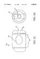
- FIG. 1Cdepicts the structure of one embodiment of the diaphysial cortical dowel of this invention.
- FIG. 2Adepicts the ACF dowel with the instrument attachment hole and score mark.
- FIG. 2Bdepicts the ATIF or ALIF dowel with the instrument attachment hole and score mark.
- FIGS. 3A and 3Bdepict one embodiment of this invention in which the dowel is threaded.
- FIGS. 3C and 3Ddepict one embodiment of this invention in which the dowel is grooved.
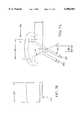
- FIG. 4Ais a side view of a dowel "blank" of this invention.
- FIG. 4Bis an end-on view of the dowel "blank”.
- FIG. 5Ais a threaded dowel of this invention.
- FIG. 5Bis an end-on view of the threaded dowel.
- FIG. 5Cis a detail of one embodiment of the thread of one embodiment of the threaded dowel of this invention.
- FIG. 6Ais a top plan view of one embodiment of a dowel threader of this invention.
- FIG. 6Bis a side view of the dowel threader of this invention.
- FIG. 6Cis an end-on view of the dowel threader of this invention showing the elements of the cutter assembly.
- FIG. 7Ais a detailed view of a single tooth of one cutter blade of the dowel threader.
- FIG. 7Bis an end-on view of the tooth profile.
- FIG. 7Cis a global side view of a cutter blade.
- FIG. 7Dis a detailed side view of cutter blade 421.
- FIG. 7Eis a detailed side view of cutter blade 422.
- the diaphysial cortical dowel of this inventionis a graft useful in cervical or thoracic and lumbar fusions.
- the dowelis preferably obtained from the fibula, radius, ulna and occasionally, from small humeri.
- the dimensions of such dowelsare typically between about 8-15 mm in length (depth) and about 10-14 mm in diameter.
- the dowelis preferably obtained from the humerus, femur or tibia.
- the dimensions of such dowelsare typically between about 10-30 mm in length (depth) and about 14°mm in diameter.
- the dowelis obtained as a transverse plug from the diaphysis of these long bones.
- the bone plugsare obtained using a diamond or hard metal tipped cutting bit which is water cleaned and cooled.
- Commercially available bitse.g. core drills
- core drillshaving a generally circular nature and an internal vacant diameter between about 10 mm to about 20 mm are amenable to use for obtention of these bone plugs.
- core drillsare available, for example, from Starlite, Inc.
- a machine for obtention of endo- and cortical dowelsconsists of a pneumatic driven miniature lathe which is fabricated from stainless steel and anodized aluminum. It has a spring loaded carriage which travels parallel to the cutter.
- the carriagerides on two runners which are 1.0 inch (2.54 cm) stainless rods and has a travel distance of approximately 8.0 inches (20.32 cm).
- One runnerhas set pin holes on the running rod which will stop the carriage from moving when the set pin is placed into the desired hole.
- the carriageis moveable from side to side with a knob which has graduations in metric and in English. This allows the graft to be positioned.
- On this carriageis a vice with clamps the graft and holds it in place while the dowel is being cut.
- the vicehas a cut out area in the jaws to allow clearance for the cutter.
- the lathehas a drive system which is a pneumatic motor with a valve controller which allows a desired RPM to be set.
- the carriageis manually pulled back and locked in place with a set pin.
- the graftis loaded into the vice and is aligned with the cutter.
- the machineis stared and the RPM is set by using a knob on the valve control.
- the set pinwhich allows the graft to be loaded onto the cutter to cut the dowel. Once the cutter has cut all the way through the graft the carriage will stop on a set pin.
- sterile wateris used to eject dowel out of the cutter. It is fully autoclavable and has a stainless steel vice and/or clamping fixture to hold grafts for cutting dowels.
- the graftcan be positioned to within 0.001" (0.3 mm) of an inch which creates dowel uniformity during the cutting process.
- the cutter used in conjunction with the above machinecan produce dowels ranging from 5 mm to 30 mm diameters and the sizes of the cutters are 10.6 mm; 11.0 mm; 12.0 mm; 13.0 mm; 14.0 mm; 16.0 mm; and 18.0 mm.
- the composition of the cuttersis stainless steel with a diamond powder cutting surface which produces a very smooth surface on the wall of the dowels.
- sterile wateris used to cool and remove debris from graft and/or dowel as the dowel is being cut (hydro infusion). The water travels down through the center of the cutter to irrigate as well as clean the dowel under pressure. In addition, the water aides in ejecting the dowel from the cutter.
- Plugs having a depth of about 8 mm to about 30 mmare, generally acceptable, with appropriate gradations in length and diameter naturally being available at the option of the machinist. Accordingly, for cervical dowels, also referred to herein as anterior cervical fusion of ACF dowels, lengths of 8 mm, 9 mm, up to about 15 mm are desirable. Dowels of differing diameter are most conveniently obtained as follows:
- Dowels for thoracic and lumbar fusionsalso referred to herein as anterior thoracic inner body fusion (ATIF) and anterior lumbar inner body fusion (ALIF) dowels, respectively, having a depth of between about 10-30 mm, and preferably between about 15-24 mm, are generally acceptable, depending on the needs of a particular patient.
- Dowels of differing diameter for thoracic and lumbar fusionsare most conveniently obtained as follows:
- a consenting donori.e., a donor card or other form of acceptance to serve as a donor
- a consenting donori.e., a donor card or other form of acceptance to serve as a donor
- communicable diseases and pathogensincluding human immunodeficiency virus, cytomegalovirus, hepatitis B, hepatitis C and several other pathogens.
- the donoror their next of kin, is interviewed to ascertain whether the donor engaged in any of a number of high risk behaviors such as having multiple sexual partners, suffering from hemophilia, engaging in intravenous drug use etc.
- the bones useful for obtention of the dowels as desribed aboveare recovered and cleaned.
- the final machined productmay be stored, frozen or freeze-dried and vacuum sealed for later use.
- each dowelSince the dowels are obtained from transverse plugs across the diaphysis of long bones, each dowel has the feature of having the natural intra-medullary canal of the source bone forming a cavity through the dowel perpendicular to the length of the dowel.
- the canal cavity in the long boneis, in vivo, filed with bone-marrow.
- no such natural cavityexists and the cancellous bone that forms the body of such dowels tends to be too brittle to accept machining of such a cavity.
- the instant dowelsby the nature of their origin, are already available with such a cavity.
- the cavitycan then be packed with autogenous bone fragments from the recipient (i.e., when the cavity between adjacent vertebrae is formed, the removed bone fragments can be used as an autogenous packing), hydroxyapatite, BIOGLASS®, mixtures of these elements or any other osteogenic material to promote rapid fusion of the vertebrae between which the dowel is inserted.
- Bioactive glassesare generally composed of SiO 2 , Na 2 O, CaO, and P 2 O 5 .
- a preferred bioactive glass, BIOGLASS® 45S5contains these compounds in the following respective weights: 45%, 24.5%; 24.4%, and 6%.
- the method for preparing and using the diaphysial cortical dowel of this inventioncomprises the steps of obtaining a plug from the diaphysis of an appropriate donor bone.
- the donorwill have been extensively screened for communicable diseases, cancer, and at-risk behavior prior to acceptance of the donor bone for dowel formation.
- the plugis then machined, preferably in a class 10 clean room, to the dimensions desired.
- the machiningis preferably conducted on a lathe such as a jeweler's lathe or machining tools may be specifically designed and adapted for this purpose. Specific tolerances for the dowels and reproduceability of the product dimensions are important features for the successful use of such dowels in the clinical setting.
- a groove 32(see FIG.
- the dowels of this inventionhave the advantage of having very good biomechanical properties amenable to such machining.
- the forward end of the dowel which is to be inserted into a cavity formed between adjacent vertebraeis preferably chamfered by appropriate abrasive means known in the art such as machining, filing or sanding.
- abrasive meansknown in the art such as machining, filing or sanding.
- the curvature of the chamfered endaids in the ease of insertion.
- the tolerance for the chamferingis fairly liberal and the desired object is merely to round or slightly point the end of the dowel that is to be inserted into the cavity formed between adjacent vertebrae to be fused.
- an instrument attachment holeis machined, for example by drilling and/or tapping. It is preferable that this end have a generally flat surface to accept the instrument for insertion of the dowel into the recipient.
- the dowelwill be of such dimensions as to fit standard insertion tools, such as those produced by Midas-Rex, Inc.
- a score markbe inscribed on the instrument attachment site of the dowel so that the surgeon can align the intra-medullary canal so that the canal is parallel with the length of the recipient's spinal column. With the aid of the score mark, once the dowel is inserted into the intervertebral cavity that is formed by the surgeon, and the canal is no longer visible, proper alignment is possible.
- FIG. 1Athere is shown, in FIG. 1A the standard unicortical dowel 100 known in the art, having a cortical surface 10, a drilled and/or tapped instrument attachment hole 15, and a body of brittle cancellous bone 20.
- FIG. 1Bthere is shown the standard bicortical dowel 200 known in the art having two cortical surfaces 10, a drilled and/or tapped instrument attachment hole 15, and a body of brittle cancellous bone 20.
- FIG. 1Cone embodiment of the novel dowel 300 of this invention is shown having a cortical surface 10 into which an instrument attachment hole 15 and alignment score mark 16 may be machined (not shown as these elements are optional but preferred). Also shown is the intramedullary canal 30 and the chamfered insertion end 40 (also optional but preferred). Also not shown but easily inscribed due to the strength of the dowel 300 are circumferential (annular) ribbing or threads.
- FIG. 2there is shown the ACF dowel in FIG. 2A and the ATIF or the ALIF dowel in FIG. 2B. Also shown, in addition to what is shown in FIG. 1, are the score mark 16 and the instrument hole 15.
- FIGS. 3A and 3Bthe threaded 31 and grooved 32 dowel of this invention are shown. While those skilled in the art would know how to prepare a grooved or threaded dowel of this invention based on the foregoing disclosure and the disclosure of application Ser. No. 08/587,070, one specific technique for preparation of preferred embodiments of this invention is discussed herein.
- FIG. 4Athere is provided a side view of a diaphysial cortical dowel of this invention, which may be used as is, or which may be further machined to have grooves or threads. For purposes of illustration only, specific dimensions of dowel diameter, length and thread pitch are provided. Those skilled in the art will recognize that these specifics may be appropriately scaled, depending on the size of the dowel required for any given application.
- a blank dowelwhich may be used to machine an 18 mm diameter by 28 mm length threaded dowel.
- Various features of the dowel blankare shown; the cortical bone 10, the tapped instrument attachment hole 15, the intra-medullary canal 30, and the chambered forward end of the dowel 40.
- the following dimensionsare also provided in inches and/or millimeters; 50--0.630" (16.0 mm); 51--0.100" (2.54 mm); 5.2--3.512" (26 mm) 54--0.50" (1.3 mm); 55--0.150" (3.8 mm); 56--0.217" (5.5 mm).
- FIG. 4GBan end-on view of the dowel blank from the instrument-attachment hole 15 (rear) end of the dowel is provided.
- the following dimensionsare provided: 57--0.7087" (18 mm).
- FIG. 5Athere is provided a view of the threaded dowel.
- the following dimensionsare provided:
- a regular or irregular hole having a diameter 58 no greater than about 0.551" (14 mm)is preferred to avoid the walls of the dowel from being too thin, and so that a minimum wall thickness 59 at the root of the thread, on both sides of the canal, is preferably 4 mm or more.
- FIG. 5Ban end-on view, from the orientation of the double arrows shown, shows the instrument attachment hole 15 and score mark 16 or driver slot 56.
- FIG. 5Cthere is shown a detail of one embodiment of the thread.
- a right hand thread with ten threads per inch at a helix angle at the root diameteris about 2.8892° is provided as follows: the pitch 60--0.100" (2.5 mm); the thread angle 61--60°; the thread crest width 62a--0.025" (0.64 mm); the thread height 63 0.039" (1 mm); and the radius of the various thread angle as it changes 64 is typically about 0.010" (0.254 mm).
- FIG. 6Athere is shown a top view of a thread cutter 400.
- a handle 401attached to a drive shaft 402 having a threaded portion 403 or a graduated segment means for controlled incremental advancement of the drive shaft 402 upon rotation of the handle 401.
- Support means 404 and 405are provided for alignment and support of the shaft 402, with either or both support means having matching threads.
- support means 405would have matching threads, while support means 404 would have a hole which may have bearings to assist in rotation of the handle 401 and shaft 402), or like graduated segment means for controlled incremental advancement of the drive shaft 402.
- a protruding element 407which corresponds in width to the driver slot 56 on the rear end of the dowel of this invention.
- a housing for the cutter assemblydescribed further below.
- the supports 404 and 405 and the housing 408 for the cutter assemblyare all mounted on a steady, solid, preferably weighty base unit 409 via screws, welding, or like attachment means at 410a-f.
- cutter blades assembly 420(comprising cutter blades 421 and 422 and guide plates 424 and 425, see FIG. 6C), is shown affixed to the cutter assembly housing 408, and an approximate travel distance 411 from the fully backed out terminal end of the drive shaft 406, to the end of the cutter assembly 420 is shown. This distance must be sufficient to allow insertion of a dowel blank and advancement of the blank through the cutter assembly 420 to allow a fully threaded dowel to emerge from the cutter assembly.
- FIG. 6Can end-on view (from the direction shown by the double arrows in FIG. 6B) of the cutter assembly 420 and cutter assembly housing 408 is provided.
- the elements of this embodiment of the cutter assemblyare now desribed in further detail: corresponding 421 and 422 cutter blades are held in place in the housing 408 by fixation wedges 423a and 423b while guide plates 424 and 425, having no cutting teeth, are held in place by fixation wedges 423c and 423d.
- Fixation wedges 423a-dare held in place by screws 426a-d.
- cutter blades 421 and 422 and guide plates 424 and 425may be fixed in place by increasing the tension created by tightening screws 426a-d, which draws the fixation wedges 423a-d into the housing 408, thereby clamping these elements in place.
- the diameter of the dowel that may be threaded according to this deviceis defined by the diameter of the aperture 427 created between the cutter blades 421 and 422 and the guide plates 424 and 425.
- all of the foregoing elementsshould preferably be manufactured from durable materials such as 440 stainless steel or like materials.
- the cutting surfaces 421a and 422a of the blades 421 and 422, described in greater detail below,are made from hard metal.
- the cutting edges 421a and 422aare disposed in relation to each other so that they are on axis.
- FIG. 7Aprovides a detail of the cutter, which maintains true tooth form from top to bottom, so that the cutter can be sharpened by surface grinding the face. This is achieved by wire-cutting the teeth such that there is about a 5° incline 62c between the descending vertices at the front and rear of each tooth, and about an 8° incline 62d between the front and rear of the top of each tooth. This aspect can best be seen in cutter blade end-on view 7B. Also, the thickness of the cutter blade: 62e, preferably about 0.100" (2.54 mm), can be seen in that figure.
- the angle 61 in FIG. 7Ais preferably about 60°.
- the width of the top of the tooth 62bis preferably about 0.025" (0.635 mm).
- the pitch 60is preferably about 0.100" (2.5 mm).
- FIG 7Cthere is shown an overall view of the cutter blades 421 or 422 which are assembled in the cutter assembly housing 408. For illustrative purposes, the following dimensions are provided.
- the entire length of the cutter blade 421bis about 1.650" (4.2 cm). Fixation wings 421c and 421d are provided to allow proper seating of the cutter blade upon insertion into the housing 408.
- a lineis provided on cutter blades 421 and 422, which allows for appropriate registration between cutter blades 421 and 422 during manufacture thereof.
- blades and the teeth thereonare appropriately registered so that as blade 421 cuts into the bone dowel as it is rotationally advanced through the cutter assembly 420, blade 422 is appropriately situated so that its matching teeth are in phase with the thread inscribed by the teeth on blade 421. This is accomplished by a combination of the fixation wings 421d and 421c properly seating in the hosing 408 such that the wall 421e abuts the housing 408 and the housing 408 walls about the insides of wings 421d and 421c.
- FIG. 7Dthere is provided a top view of cutting edge 421a.
- the cutter blade 421has twelve cutting teeth, numbered in the figure 431-442.
- the height of the toothis incremented by about 0.004" (0.1 mm), starting from about 0.002" (0.5 mm) at 431, until the final tooth height is reached, in this example, of 0.039" (1 mm) at 441 and 442.
- the truncated teeth 431-440feed into the dowel being cut along the 30° line so that the teeth cut on only two sides.
- the dotted line 443shows that the final pitch and form that the cutter will cut in the bone dowel. Similar to the foregoing description for FIG. 7D above, the cutting edge 422a is shown in greater detail in FIG. 7E, with eleven teeth 451-461 spread over the length of the blade. At 451, the first tooth at 0.004" (0.1 mm) in this example is encountered by the blank and at each successive tooth, an increase of about 0.004" (0.1 mm) is made until the final tooth height of about 0.039" (1 mm) reached at 460 and 461. Again, the dotted line 443 shows the final pitch and form that the cutter will cut in the bone dowel.
- the cutter blades 421 and 422are placed into the housing 408, clamped into place via the fixation wedges 423 and the screws 426, after the blades have been properly seated and the two blades are perfectly aligned.
- a blank dowelis then loaded into the orifice 427 and the drive shaft with the protruding element 407 is inserted into the driver slot 56 of the dowel 300.
- the score mark 16may be matched as a groove (driver slot 56) which mates with the protruding element 407 such that rotational torque may be transmitted to the dowel.
- the groovemay be oriented parallel to, perpendicular to, or at any other desired orientation with respect to the intramedullary canal of the dowel.
- the handle 401is turned, forcing the dowel to rotate and advance incrementally through the cutter assembly 420, thereby inscribing the thread defined by the cutter blades 421 and 422 into the cylindrical surface (circumference) of the dowel.
- the dowelcould be mounted in a lathe, such as those known in the art and commercially available, for example from SHERLINE PRODUCTS INC. SAN MARCOS, Calif. 92069, and a cutter blade applied as the dowel is rotated.
- a dowel made from bonecomprising a portion of the intra-medullary canal
- the portion of the canal contained within the dowel of this inventionmay be treated to modify the shape, size, texture, and composition thereof, without departing from the scope of the invention disclosed and claimed herein.
- Any desirable external feature, including grooves, threads, cross-hatching, indentations, coatings and the likecome within the scope of this invention and the appended claims.
- the dowel of this inventionmay be conveniently incorporated into known fusion procedures.
- the surgeoncreates a cavity between adjacent vertebrae that are to be fused, using conventional surgical procedures.
- the autogenous bone fragments produced in the formation of the cavitymay be collected and packed into the intra-medullary canal of the diaphysial cortical dowel, or the dowel may be used with a pre-packaged osteogenic composition.
- a dowel of the appropriate dimensionsis selected by the surgeon, based on the size of the cavity created and the needs of the particular patient undergoing the fusion.
- the dowelis mounted on an instrument via the instrument attachment hole and carefully inserted into the cavity created between the adjacent vertebra to be fused. For cervical fusions, only one dowel is needed. For lumbar fusions, two dowels may be required. In any event, the dowels may be applied laparoscopically using currently available instrumentation. Over a period of several months, it is found that substantial fusion of the adjacent vertebrae occurs.
- ProcedureThe procedure utilized the above materials to compress the ACF dowels to failure and calculate their rupture modulus.
- the patientwas prepped and draped in the routine fashion. Incision was made in the skin length of the neck and carried through the platysma muscle. Dissection was carried down to expose the anterior vertebral column and the appropriate space identified by x-ray. Discectomy and foraminotomy were then performed and there was found a central, extruded fragment of disc toward the right side. When adequate decompression had been achieved, a bone dowel was cut from bone bank fibula and counter-sunk between the vertebral bodies to afford distraction. The wound was then irrigated with Bacitracin and closed in layers with Dexon and steri strips.
- a combination bone grafting unitcomprising: a cortical shell having a selected outer shape wherein a cavity is formed therein, into which a cancellous plug is inserted.
- a cortical dowel, graft or threaded dowelis provided wherein a portion of the intra-medullary canal of a bone is included in the device to provide a canal running through the device, into which osteogenic material may be packed.
Landscapes
- Health & Medical Sciences (AREA)
- Life Sciences & Earth Sciences (AREA)
- Engineering & Computer Science (AREA)
- Biomedical Technology (AREA)
- Orthopedic Medicine & Surgery (AREA)
- Surgery (AREA)
- Oral & Maxillofacial Surgery (AREA)
- Heart & Thoracic Surgery (AREA)
- Veterinary Medicine (AREA)
- Animal Behavior & Ethology (AREA)
- General Health & Medical Sciences (AREA)
- Public Health (AREA)
- Transplantation (AREA)
- Neurology (AREA)
- Vascular Medicine (AREA)
- Dentistry (AREA)
- Nuclear Medicine, Radiotherapy & Molecular Imaging (AREA)
- Cardiology (AREA)
- Medical Informatics (AREA)
- Molecular Biology (AREA)
- Prostheses (AREA)
- Materials For Medical Uses (AREA)
- Acyclic And Carbocyclic Compounds In Medicinal Compositions (AREA)
- Saccharide Compounds (AREA)
- Surgical Instruments (AREA)
- Pharmaceuticals Containing Other Organic And Inorganic Compounds (AREA)
- Dental Preparations (AREA)
- Adornments (AREA)
Abstract
Description
______________________________________ Diameter Source ______________________________________ 10.6-11 mm fibula 12 mm radius 14 mm ulna 14+ mm small humeri ______________________________________
______________________________________ Diameter Source ______________________________________ 14-16 mm humerus 16-18 mm femur 18-20 mm tibia ______________________________________
______________________________________ Maximum Load Minimum Load Mean Load Median ______________________________________ 383 kg 200 kg 267.14 kg 264 kg 3743 Newtons 1960 Newtons 2618 Newtons 2587 Newtons ______________________________________
Claims (41)
Priority Applications (1)
| Application Number | Priority Date | Filing Date | Title |
|---|---|---|---|
| US09/101,903US6096081A (en) | 1996-01-16 | 1997-01-16 | Diaphysial cortical dowel |
Applications Claiming Priority (3)
| Application Number | Priority Date | Filing Date | Title |
|---|---|---|---|
| US08/587,070US5814084A (en) | 1996-01-16 | 1996-01-16 | Diaphysial cortical dowel |
| US09/101,903US6096081A (en) | 1996-01-16 | 1997-01-16 | Diaphysial cortical dowel |
| PCT/US1997/000630WO1997025945A1 (en) | 1996-01-16 | 1997-01-16 | Diaphysial cortical dowel |
Related Parent Applications (1)
| Application Number | Title | Priority Date | Filing Date |
|---|---|---|---|
| US08/587,070Continuation-In-PartUS5814084A (en) | 1996-01-16 | 1996-01-16 | Diaphysial cortical dowel |
Publications (1)
| Publication Number | Publication Date |
|---|---|
| US6096081Atrue US6096081A (en) | 2000-08-01 |
Family
ID=24348217
Family Applications (2)
| Application Number | Title | Priority Date | Filing Date |
|---|---|---|---|
| US08/587,070Expired - LifetimeUS5814084A (en) | 1996-01-16 | 1996-01-16 | Diaphysial cortical dowel |
| US09/101,903Expired - LifetimeUS6096081A (en) | 1996-01-16 | 1997-01-16 | Diaphysial cortical dowel |
Family Applications Before (1)
| Application Number | Title | Priority Date | Filing Date |
|---|---|---|---|
| US08/587,070Expired - LifetimeUS5814084A (en) | 1996-01-16 | 1996-01-16 | Diaphysial cortical dowel |
Country Status (12)
| Country | Link |
|---|---|
| US (2) | US5814084A (en) |
| EP (1) | EP0876129B1 (en) |
| JP (1) | JP3935506B2 (en) |
| AT (1) | ATE224680T1 (en) |
| AU (1) | AU704228B2 (en) |
| CA (1) | CA2243152C (en) |
| CZ (1) | CZ220698A3 (en) |
| DE (1) | DE69715817T2 (en) |
| ES (1) | ES2186865T3 (en) |
| HU (1) | HUP9902187A3 (en) |
| PL (1) | PL328226A1 (en) |
| WO (1) | WO1997025945A1 (en) |
Cited By (88)
| Publication number | Priority date | Publication date | Assignee | Title |
|---|---|---|---|---|
| US20020029084A1 (en)* | 1998-08-03 | 2002-03-07 | Paul David C. | Bone implants with central chambers |
| US6371988B1 (en)* | 1996-10-23 | 2002-04-16 | Sdgi Holdings, Inc. | Bone grafts |
| US20020065560A1 (en)* | 2000-06-12 | 2002-05-30 | Ortho Development Corporation | Intervertebral spacing implant system |
| US6442814B1 (en) | 1999-04-23 | 2002-09-03 | Spinal Concepts, Inc. | Apparatus for manufacturing a bone dowel |
| US6443987B1 (en) | 2000-09-15 | 2002-09-03 | Donald W. Bryan | Spinal vertebral implant |
| US6458144B1 (en)* | 1999-12-30 | 2002-10-01 | Osteotech, Inc. | Methods for manufacturing skeletal implants |
| US6500206B1 (en) | 2000-09-15 | 2002-12-31 | Donald W. Bryan | Instruments for inserting spinal vertebral implant |
| US20030028197A1 (en)* | 2000-07-06 | 2003-02-06 | Hanson David A. | Bone implants and methods |
| US20030045935A1 (en)* | 2001-02-28 | 2003-03-06 | Angelucci Christopher M. | Laminoplasty implants and methods of use |
| US6530955B2 (en)* | 1999-06-08 | 2003-03-11 | Osteotech, Inc. | Ramp-shaped intervertebral implant |
| US6554863B2 (en) | 1998-08-03 | 2003-04-29 | Synthes | Intervertebral allograft spacer |
| US6557226B1 (en) | 1999-04-23 | 2003-05-06 | Michael E. Landry | Apparatus for manufacturing a bone dowel |
| US6562073B2 (en) | 2001-02-06 | 2003-05-13 | Sdgi Holding, Inc. | Spinal bone implant |
| US6576017B2 (en) | 2001-02-06 | 2003-06-10 | Sdgi Holdings, Inc. | Spinal implant with attached ligament and methods |
| US20030171814A1 (en)* | 2000-09-08 | 2003-09-11 | Muhanna Nabil L. | System and methods for inserting a vertebral spacer |
| US6632247B2 (en) | 2000-03-22 | 2003-10-14 | Synthes (Usa) | Implants formed of coupled bone |
| US6635087B2 (en) | 2001-08-29 | 2003-10-21 | Christopher M. Angelucci | Laminoplasty implants and methods of use |
| US20040034362A1 (en)* | 2000-12-21 | 2004-02-19 | Stryker Spine | Bone graft forming guide |
| US20040073309A1 (en)* | 1997-06-03 | 2004-04-15 | Bianchi John R. | Open intervertebral spacer |
| US20040088055A1 (en)* | 2001-02-16 | 2004-05-06 | Hanson David A | Bone implants and methods |
| US20040093083A1 (en)* | 1998-10-28 | 2004-05-13 | Branch Charles L. | Interbody fusion grafts and instrumentation |
| US20040122518A1 (en)* | 2002-12-19 | 2004-06-24 | Rhoda William S. | Intervertebral implant |
| USD493225S1 (en) | 2000-06-12 | 2004-07-20 | Ortho Development Corporation | Implant |
| USRE38614E1 (en) | 1998-01-30 | 2004-10-05 | Synthes (U.S.A.) | Intervertebral allograft spacer |
| US20040219182A1 (en)* | 2003-04-29 | 2004-11-04 | Gomes Katherine A. | Novel glue for cartilage repair |
| US20040249377A1 (en)* | 2001-07-12 | 2004-12-09 | Kaes David R. | Intervertebral implant with movement resistant structure |
| US20050064042A1 (en)* | 2003-04-29 | 2005-03-24 | Musculoskeletal Transplant Foundation | Cartilage implant plug with fibrin glue and method for implantation |
| US20050131417A1 (en)* | 2003-08-22 | 2005-06-16 | Ahern James W. | Kit for treating bony defects |
| US20050125986A1 (en)* | 2003-12-16 | 2005-06-16 | Stryker Spine | Apparatus and method for cutting spinal implants |
| US20050159817A1 (en)* | 2002-04-24 | 2005-07-21 | Ferree Bret A. | Annulus preserving methods and apparatus for placement of intradiscal devices |
| US20050177236A1 (en)* | 2002-02-19 | 2005-08-11 | Claude Mathieu | Intervertebral implant |
| US20050177165A1 (en)* | 2004-02-11 | 2005-08-11 | Kerry Zang | Conical, threaded subtalar implant |
| US6986788B2 (en) | 1998-01-30 | 2006-01-17 | Synthes (U.S.A.) | Intervertebral allograft spacer |
| US20060085071A1 (en)* | 2003-02-06 | 2006-04-20 | Beat Lechmann | Intervertebral implant |
| US20060111781A1 (en)* | 2004-11-22 | 2006-05-25 | Orthopedic Development Corporation | Implant device used in minimally invasive facet joint hemi-arthroplasty |
| US20060111786A1 (en)* | 2004-11-22 | 2006-05-25 | Orthopedic Development Corporation | Metallic prosthetic implant for use in minimally invasive acromio-clavicular shoulder joint hemi-arthroplasty |
| US7056321B2 (en) | 2000-08-01 | 2006-06-06 | Endius, Incorporated | Method of securing vertebrae |
| US20070043438A1 (en)* | 2005-07-14 | 2007-02-22 | Baylor College Of Medicine | Bone and ligament graft modification system |
| US20070050028A1 (en)* | 2005-08-26 | 2007-03-01 | Conner E S | Spinal implants and methods of providing dynamic stability to the spine |
| US7226482B2 (en) | 2003-09-02 | 2007-06-05 | Synthes (U.S.A.) | Multipiece allograft implant |
| US7488348B2 (en) | 2003-05-16 | 2009-02-10 | Musculoskeletal Transplant Foundation | Cartilage allograft plug |
| US20090099603A1 (en)* | 2005-08-11 | 2009-04-16 | National University Corporation Kobe University | Minimally-Invasive Implant for Opening and Enlargement of Processus Spinosus Interspace and Method of Percutaneously Enlarging Processus Spinosus Interspace Therewith |
| US7662185B2 (en) | 1999-12-30 | 2010-02-16 | Osteotech, Inc. | Intervertebral implants |
| US20100057207A1 (en)* | 1996-10-23 | 2010-03-04 | Ray Iii Eddie F | Bone grafts |
| US7708761B2 (en) | 2004-11-22 | 2010-05-04 | Minsurg International, Inc. | Spinal plug for a minimally invasive facet joint fusion system |
| US7726002B2 (en) | 2001-12-05 | 2010-06-01 | Osteotech, Inc. | Processes for making spinal intervertebral implant, interconnections for such implant |
| US7780708B2 (en) | 2000-10-20 | 2010-08-24 | Osteotech, Inc. | Implant retaining device |
| US7815926B2 (en) | 2005-07-11 | 2010-10-19 | Musculoskeletal Transplant Foundation | Implant for articular cartilage repair |
| US7837740B2 (en) | 2007-01-24 | 2010-11-23 | Musculoskeletal Transplant Foundation | Two piece cancellous construct for cartilage repair |
| US20100305704A1 (en)* | 2006-02-27 | 2010-12-02 | Synthes Gmbh | Intervertebral implant with fixation geometry |
| US7879103B2 (en) | 2005-04-15 | 2011-02-01 | Musculoskeletal Transplant Foundation | Vertebral disc repair |
| US7901457B2 (en) | 2003-05-16 | 2011-03-08 | Musculoskeletal Transplant Foundation | Cartilage allograft plug |
| US7959683B2 (en) | 2006-07-25 | 2011-06-14 | Musculoskeletal Transplant Foundation | Packed demineralized cancellous tissue forms for disc nucleus augmentation, restoration, or replacement and methods of implantation |
| US7985247B2 (en) | 2000-08-01 | 2011-07-26 | Zimmer Spine, Inc. | Methods and apparatuses for treating the spine through an access device |
| US20110238183A1 (en)* | 2009-09-26 | 2011-09-29 | Maly Richard S | Interbody Fusion Device |
| US8043377B2 (en) | 2006-09-02 | 2011-10-25 | Osprey Biomedical, Inc. | Implantable intervertebral fusion device |
| WO2012097506A1 (en)* | 2011-01-19 | 2012-07-26 | 北京大学第三医院 | Matrix for repairing and regenerating articular cartilage and method for preparing the matrix |
| US8292968B2 (en) | 2004-10-12 | 2012-10-23 | Musculoskeletal Transplant Foundation | Cancellous constructs, cartilage particles and combinations of cancellous constructs and cartilage particles |
| US8333985B2 (en) | 2004-01-27 | 2012-12-18 | Warsaw Orthopedic, Inc. | Non-glycerol stabilized bone graft |
| US20120330360A1 (en)* | 2010-03-09 | 2012-12-27 | National University Corporation Kobe University | Inter-spinous process implant |
| US8372157B2 (en) | 2007-02-12 | 2013-02-12 | Warsaw Orthopedic, Inc. | Joint revision implant |
| US8435551B2 (en) | 2007-03-06 | 2013-05-07 | Musculoskeletal Transplant Foundation | Cancellous construct with support ring for repair of osteochondral defects |
| US8540774B2 (en) | 2007-11-16 | 2013-09-24 | DePuy Synthes Products, LLC | Low profile intervertebral implant |
| US8540746B2 (en) | 1998-08-20 | 2013-09-24 | Zimmer Spine, Inc. | Cannula for receiving surgical instruments |
| US8628575B2 (en) | 2000-08-29 | 2014-01-14 | Nabil L. Muhanna | Vertebral body replacement and method of use |
| US8961606B2 (en) | 2011-09-16 | 2015-02-24 | Globus Medical, Inc. | Multi-piece intervertebral implants |
| US9039775B2 (en) | 2003-03-31 | 2015-05-26 | DePuy Synthes Products, Inc. | Spinal fixation plates |
| US9149365B2 (en) | 2013-03-05 | 2015-10-06 | Globus Medical, Inc. | Low profile plate |
| US9192419B2 (en) | 2008-11-07 | 2015-11-24 | DePuy Synthes Products, Inc. | Zero-profile interbody spacer and coupled plate assembly |
| US9204975B2 (en) | 2011-09-16 | 2015-12-08 | Globus Medical, Inc. | Multi-piece intervertebral implants |
| US9220604B2 (en) | 2010-12-21 | 2015-12-29 | DePuy Synthes Products, Inc. | Intervertebral implants, systems, and methods of use |
| US9237957B2 (en) | 2011-09-16 | 2016-01-19 | Globus Medical, Inc. | Low profile plate |
| US9241809B2 (en) | 2010-12-21 | 2016-01-26 | DePuy Synthes Products, Inc. | Intervertebral implants, systems, and methods of use |
| US9398960B2 (en) | 2011-09-16 | 2016-07-26 | Globus Medical, Inc. | Multi-piece intervertebral implants |
| US9539109B2 (en) | 2011-09-16 | 2017-01-10 | Globus Medical, Inc. | Low profile plate |
| US9681959B2 (en) | 2011-09-16 | 2017-06-20 | Globus Medical, Inc. | Low profile plate |
| US9701940B2 (en) | 2005-09-19 | 2017-07-11 | Histogenics Corporation | Cell-support matrix having narrowly defined uniformly vertically and non-randomly organized porosity and pore density and a method for preparation thereof |
| US9707099B2 (en) | 2013-03-15 | 2017-07-18 | NuTech Spine, Inc. | Anterior lumbar fusion method and device |
| US9770340B2 (en) | 2011-09-16 | 2017-09-26 | Globus Medical, Inc. | Multi-piece intervertebral implants |
| US9848994B2 (en) | 2011-09-16 | 2017-12-26 | Globus Medical, Inc. | Low profile plate |
| US9867718B2 (en) | 2014-10-22 | 2018-01-16 | DePuy Synthes Products, Inc. | Intervertebral implants, systems, and methods of use |
| US10077420B2 (en) | 2014-12-02 | 2018-09-18 | Histogenics Corporation | Cell and tissue culture container |
| US10245155B2 (en) | 2011-09-16 | 2019-04-02 | Globus Medical, Inc. | Low profile plate |
| US10271960B2 (en) | 2017-04-05 | 2019-04-30 | Globus Medical, Inc. | Decoupled spacer and plate and method of installing the same |
| US10376385B2 (en) | 2017-04-05 | 2019-08-13 | Globus Medical, Inc. | Decoupled spacer and plate and method of installing the same |
| US10478313B1 (en) | 2014-01-10 | 2019-11-19 | Nuvasive, Inc. | Spinal fusion implant and related methods |
| US11717417B2 (en) | 2011-09-16 | 2023-08-08 | Globus Medical Inc. | Low profile plate |
| US20250177163A1 (en)* | 2022-03-04 | 2025-06-05 | Intelivation Technologies Llc | Implantable cages and plates having alignment markings and related methods of using the same |
Families Citing this family (147)
| Publication number | Priority date | Publication date | Assignee | Title |
|---|---|---|---|---|
| US5989289A (en) | 1995-10-16 | 1999-11-23 | Sdgi Holdings, Inc. | Bone grafts |
| US5814084A (en)* | 1996-01-16 | 1998-09-29 | University Of Florida Tissue Bank, Inc. | Diaphysial cortical dowel |
| US6111164A (en)* | 1996-06-21 | 2000-08-29 | Musculoskeletal Transplant Foundation | Bone graft insert |
| US5895426A (en) | 1996-09-06 | 1999-04-20 | Osteotech, Inc. | Fusion implant device and method of use |
| FR2767675B1 (en)* | 1997-08-26 | 1999-12-03 | Materiel Orthopedique En Abreg | INTERSOMATIC IMPLANT AND ANCILLARY OF PREPARATION SUITABLE FOR ALLOWING ITS POSITION |
| WO1999009914A1 (en)* | 1997-08-27 | 1999-03-04 | University Of Florida Tissue Bank, Inc. | Cortical bone cervical smith-robinson fusion implant |
| US20010031254A1 (en)* | 1998-11-13 | 2001-10-18 | Bianchi John R. | Assembled implant |
| EP1009338B1 (en)* | 1997-08-27 | 2006-10-04 | Regeneration Technologies, Inc. | Cortical bone cervical smith-robinson fusion implant |
| US6482584B1 (en) | 1998-11-13 | 2002-11-19 | Regeneration Technologies, Inc. | Cyclic implant perfusion cleaning and passivation process |
| US8291572B2 (en) | 1997-08-27 | 2012-10-23 | Rti Biologics, Inc. | Multi-component cortical bone assembled implant |
| FR2769827B1 (en)* | 1997-10-17 | 2000-05-19 | Sdm | IMPLANT FOR INTERSOMATIC SPINAL ARTHRODESIS |
| US6511509B1 (en) | 1997-10-20 | 2003-01-28 | Lifenet | Textured bone allograft, method of making and using same |
| US6652592B1 (en) | 1997-10-27 | 2003-11-25 | Regeneration Technologies, Inc. | Segmentally demineralized bone implant |
| US6090998A (en) | 1997-10-27 | 2000-07-18 | University Of Florida | Segmentally demineralized bone implant |
| DE19751284A1 (en)* | 1997-11-19 | 1999-05-27 | Leo Prof Dr Gotzen | Fixation element |
| US6143033A (en)* | 1998-01-30 | 2000-11-07 | Synthes (Usa) | Allogenic intervertebral implant |
| US6241769B1 (en)* | 1998-05-06 | 2001-06-05 | Cortek, Inc. | Implant for spinal fusion |
| US6368325B1 (en) | 1998-05-27 | 2002-04-09 | Nuvasive, Inc. | Bone blocks and methods for inserting bone blocks into intervertebral spaces |
| US6251140B1 (en) | 1998-05-27 | 2001-06-26 | Nuvasive, Inc. | Interlocking spinal inserts |
| US6290724B1 (en) | 1998-05-27 | 2001-09-18 | Nuvasive, Inc. | Methods for separating and stabilizing adjacent vertebrae |
| US6086593A (en) | 1998-06-30 | 2000-07-11 | Bonutti; Peter M. | Method and apparatus for use in operating on a bone |
| JP4156197B2 (en)* | 1998-08-06 | 2008-09-24 | ウォーソー・オーソペディック・インコーポレーテッド | Composite intervertebral spacer |
| US6099531A (en)* | 1998-08-20 | 2000-08-08 | Bonutti; Peter M. | Changing relationship between bones |
| US7125403B2 (en) | 1998-12-08 | 2006-10-24 | Intuitive Surgical | In vivo accessories for minimally invasive robotic surgery |
| DE60022620T2 (en) | 1999-01-11 | 2006-06-22 | SDGI Holdings, Inc., Wilmington | INTERMEDIATE SPACER WITH ACCESSIBLE INTERIOR THROUGH SIDE WALLS |
| US6547823B2 (en)* | 1999-01-22 | 2003-04-15 | Osteotech, Inc. | Intervertebral implant |
| US6696073B2 (en) | 1999-02-23 | 2004-02-24 | Osteotech, Inc. | Shaped load-bearing osteoimplant and methods of making same |
| US6294187B1 (en) | 1999-02-23 | 2001-09-25 | Osteotech, Inc. | Load-bearing osteoimplant, method for its manufacture and method of repairing bone using same |
| US8133421B2 (en)* | 1999-02-23 | 2012-03-13 | Warsaw Orthopedic, Inc. | Methods of making shaped load-bearing osteoimplant |
| US20070233272A1 (en)* | 1999-02-23 | 2007-10-04 | Boyce Todd M | Shaped load-bearing osteoimplant and methods of making same |
| US6241770B1 (en) | 1999-03-05 | 2001-06-05 | Gary K. Michelson | Interbody spinal fusion implant having an anatomically conformed trailing end |
| CA2363254C (en) | 1999-03-07 | 2009-05-05 | Discure Ltd. | Method and apparatus for computerized surgery |
| US6156070A (en)* | 1999-03-26 | 2000-12-05 | Howmedica Osteonics Corp. | Allograft prosthetic joints and method |
| AU4988700A (en) | 1999-05-05 | 2000-11-17 | Gary K. Michelson | Spinal fusion implants with opposed locking screws |
| EP1198208B1 (en)* | 1999-05-05 | 2013-07-10 | Warsaw Orthopedic, Inc. | Nested interbody spinal fusion implants |
| US7201776B2 (en)* | 1999-10-08 | 2007-04-10 | Ferree Bret A | Artificial intervertebral disc replacements with endplates |
| US6527773B1 (en)* | 1999-10-07 | 2003-03-04 | Osteotech, Inc. | Cervical dowel and insertion tool |
| US7060100B2 (en)* | 1999-10-08 | 2006-06-13 | Ferree Bret A | Artificial disc and joint replacements with modular cushioning components |
| US6494883B1 (en)* | 2000-05-26 | 2002-12-17 | Bret A. Ferree | Bone reinforcers |
| US20040172019A1 (en)* | 1999-10-08 | 2004-09-02 | Ferree Bret A. | Reinforcers for artificial disc replacement methods and apparatus |
| US7201774B2 (en)* | 1999-10-08 | 2007-04-10 | Ferree Bret A | Artificial intervertebral disc replacements incorporating reinforced wall sections |
| US6592624B1 (en) | 1999-11-24 | 2003-07-15 | Depuy Acromed, Inc. | Prosthetic implant element |
| US6447512B1 (en) | 2000-01-06 | 2002-09-10 | Spinal Concepts, Inc. | Instrument and method for implanting an interbody fusion device |
| US6379385B1 (en) | 2000-01-06 | 2002-04-30 | Tutogen Medical Gmbh | Implant of bone matter |
| US6893462B2 (en)* | 2000-01-11 | 2005-05-17 | Regeneration Technologies, Inc. | Soft and calcified tissue implants |
| WO2001078798A1 (en)* | 2000-02-10 | 2001-10-25 | Regeneration Technologies, Inc. | Assembled implant |
| US7182781B1 (en)* | 2000-03-02 | 2007-02-27 | Regeneration Technologies, Inc. | Cervical tapered dowel |
| WO2001070136A2 (en)* | 2000-03-22 | 2001-09-27 | Synthes (U.S.A) | Plugs for filling bony defects |
| AU2001249369A1 (en)* | 2000-03-22 | 2001-10-03 | Boyer Ii, Michael L. | Multipiece implants formed of bone material |
| US7462195B1 (en) | 2000-04-19 | 2008-12-09 | Warsaw Orthopedic, Inc. | Artificial lumbar interbody spinal implant having an asymmetrical leading end |
| US6350283B1 (en) | 2000-04-19 | 2002-02-26 | Gary K. Michelson | Bone hemi-lumbar interbody spinal implant having an asymmetrical leading end and method of installation thereof |
| AU2001274821A1 (en)* | 2000-06-13 | 2001-12-24 | Gary K. Michelson | Manufactured major long bone ring implant shaped to conform to a prepared intervertebral implantation space |
| US20020111680A1 (en)* | 2000-06-13 | 2002-08-15 | Michelson Gary K. | Ratcheted bone dowel |
| US6852126B2 (en) | 2000-07-17 | 2005-02-08 | Nuvasive, Inc. | Stackable interlocking intervertebral support system |
| US6638310B2 (en) | 2000-07-26 | 2003-10-28 | Osteotech, Inc. | Intervertebral spacer and implant insertion instrumentation |
| AU2001280962A1 (en)* | 2000-08-01 | 2002-02-13 | Regeneration Technologies, Inc. | Diaphysial cortical dowel |
| US6761738B1 (en)* | 2000-09-19 | 2004-07-13 | Sdgi Holdings, Inc. | Reinforced molded implant formed of cortical bone |
| US6520993B2 (en) | 2000-12-29 | 2003-02-18 | Depuy Acromed, Inc. | Spinal implant |
| US6989031B2 (en) | 2001-04-02 | 2006-01-24 | Sdgi Holdings, Inc. | Hemi-interbody spinal implant manufactured from a major long bone ring or a bone composite |
| US6749636B2 (en) | 2001-04-02 | 2004-06-15 | Gary K. Michelson | Contoured spinal fusion implants made of bone or a bone composite material |
| US6890355B2 (en)* | 2001-04-02 | 2005-05-10 | Gary K. Michelson | Artificial contoured spinal fusion implants made of a material other than bone |
| EP1417000B1 (en) | 2001-07-11 | 2018-07-11 | Nuvasive, Inc. | System for determining nerve proximity during surgery |
| US7018412B2 (en) | 2001-08-20 | 2006-03-28 | Ebi, L.P. | Allograft spinal implant |
| JP2005503857A (en) | 2001-09-25 | 2005-02-10 | ヌバシブ, インコーポレイテッド | Systems and methods for performing surgical procedures and surgical diagnosis |
| EP1439802A2 (en)* | 2001-10-30 | 2004-07-28 | Osteotech, Inc. | Bone implant and insertion tools |
| US6923814B1 (en) | 2001-10-30 | 2005-08-02 | Nuvasive, Inc. | System and methods for cervical spinal fusion |
| US8025684B2 (en)* | 2001-11-09 | 2011-09-27 | Zimmer Spine, Inc. | Instruments and methods for inserting a spinal implant |
| EP1482877B1 (en) | 2002-03-11 | 2007-05-30 | Spinal Concepts Inc. | Instrumentation for implanting spinal implant devices |
| WO2003101175A2 (en)* | 2002-05-30 | 2003-12-11 | Osteotech, Inc. | Method and apparatus for machining a surgical implant |
| US7618423B1 (en) | 2002-06-15 | 2009-11-17 | Nuvasive, Inc. | System and method for performing spinal fusion |
| US7582058B1 (en) | 2002-06-26 | 2009-09-01 | Nuvasive, Inc. | Surgical access system and related methods |
| US6793678B2 (en) | 2002-06-27 | 2004-09-21 | Depuy Acromed, Inc. | Prosthetic intervertebral motion disc having dampening |
| US7776049B1 (en) | 2002-10-02 | 2010-08-17 | Nuvasive, Inc. | Spinal implant inserter, implant, and method |
| US8137284B2 (en) | 2002-10-08 | 2012-03-20 | Nuvasive, Inc. | Surgical access system and related methods |
| US7691057B2 (en) | 2003-01-16 | 2010-04-06 | Nuvasive, Inc. | Surgical access system and related methods |
| WO2004084742A1 (en) | 2003-03-24 | 2004-10-07 | Theken Surgical Llc | Spinal implant adjustment device |
| US7806932B2 (en) | 2003-08-01 | 2010-10-05 | Zimmer Spine, Inc. | Spinal implant |
| US20060229627A1 (en) | 2004-10-29 | 2006-10-12 | Hunt Margaret M | Variable angle spinal surgery instrument |
| US7905840B2 (en) | 2003-10-17 | 2011-03-15 | Nuvasive, Inc. | Surgical access system and related methods |
| JP4463819B2 (en) | 2003-09-25 | 2010-05-19 | ヌヴァシヴ インコーポレイテッド | Surgical access system |
| US7918891B1 (en)* | 2004-03-29 | 2011-04-05 | Nuvasive Inc. | Systems and methods for spinal fusion |
| US7544208B1 (en) | 2004-05-03 | 2009-06-09 | Theken Spine, Llc | Adjustable corpectomy apparatus |
| US7988699B2 (en)* | 2004-10-19 | 2011-08-02 | Warsaw Orthopedic, Inc. | Adjustable instrumentation for spinal implant insertion |
| JP4025827B2 (en)* | 2005-02-10 | 2007-12-26 | フジコピアン株式会社 | Transfer pressure sensitive adhesive tape |
| USD530423S1 (en) | 2005-03-29 | 2006-10-17 | Nuvasive, Inc. | Intervertebral implant |
| US20060247634A1 (en)* | 2005-05-02 | 2006-11-02 | Warner Kenneth D | Spinous Process Spacer Implant and Technique |
| US8623088B1 (en) | 2005-07-15 | 2014-01-07 | Nuvasive, Inc. | Spinal fusion implant and related methods |
| US7867277B1 (en)* | 2005-07-15 | 2011-01-11 | Nuvasive Inc. | Spinal fusion implant and related methods |
| US8147521B1 (en) | 2005-07-20 | 2012-04-03 | Nuvasive, Inc. | Systems and methods for treating spinal deformities |
| US8328851B2 (en) | 2005-07-28 | 2012-12-11 | Nuvasive, Inc. | Total disc replacement system and related methods |
| US7815682B1 (en) | 2005-09-24 | 2010-10-19 | Nuvasive, Inc. | Spinal fusion implant and related methods |
| JP2007195571A (en)* | 2006-01-23 | 2007-08-09 | Shimane Univ | Bone screw for osteosynthesis |
| USD741488S1 (en) | 2006-07-17 | 2015-10-20 | Nuvasive, Inc. | Spinal fusion implant |
| WO2008070863A2 (en) | 2006-12-07 | 2008-06-12 | Interventional Spine, Inc. | Intervertebral implant |
| USD580551S1 (en) | 2007-02-01 | 2008-11-11 | Zimmer Spine, Inc. | Spinal implant |
| US8673005B1 (en) | 2007-03-07 | 2014-03-18 | Nuvasive, Inc. | System and methods for spinal fusion |
| US8480715B2 (en) | 2007-05-22 | 2013-07-09 | Zimmer Spine, Inc. | Spinal implant system and method |
| US8900307B2 (en) | 2007-06-26 | 2014-12-02 | DePuy Synthes Products, LLC | Highly lordosed fusion cage |
| US8685099B2 (en) | 2007-08-14 | 2014-04-01 | Warsaw Orthopedic, Inc. | Multiple component osteoimplant |
| USD671645S1 (en) | 2007-09-18 | 2012-11-27 | Nuvasive, Inc. | Intervertebral implant |
| US9101491B2 (en) | 2007-12-28 | 2015-08-11 | Nuvasive, Inc. | Spinal surgical implant and related methods |
| EP2237748B1 (en) | 2008-01-17 | 2012-09-05 | Synthes GmbH | An expandable intervertebral implant |
| US8083796B1 (en) | 2008-02-29 | 2011-12-27 | Nuvasive, Inc. | Implants and methods for spinal fusion |
| USD599019S1 (en) | 2008-03-07 | 2009-08-25 | Nuvasive, Inc. | Spinal fusion implant |
| US8936641B2 (en) | 2008-04-05 | 2015-01-20 | DePuy Synthes Products, LLC | Expandable intervertebral implant |
| USD621509S1 (en) | 2008-10-15 | 2010-08-10 | Nuvasive, Inc. | Intervertebral implant |
| USD754346S1 (en) | 2009-03-02 | 2016-04-19 | Nuvasive, Inc. | Spinal fusion implant |
| US9387090B2 (en) | 2009-03-12 | 2016-07-12 | Nuvasive, Inc. | Vertebral body replacement |
| US9687357B2 (en) | 2009-03-12 | 2017-06-27 | Nuvasive, Inc. | Vertebral body replacement |
| FR2943238B1 (en)* | 2009-03-18 | 2013-04-26 | Fournitures Hospitalieres Ind | EXTRACTION OF A HIP PROTHESIS FASTENING SCREW |
| US9526620B2 (en) | 2009-03-30 | 2016-12-27 | DePuy Synthes Products, Inc. | Zero profile spinal fusion cage |
| US9351845B1 (en) | 2009-04-16 | 2016-05-31 | Nuvasive, Inc. | Method and apparatus for performing spine surgery |
| US8287597B1 (en) | 2009-04-16 | 2012-10-16 | Nuvasive, Inc. | Method and apparatus for performing spine surgery |
| US20110040332A1 (en)* | 2009-08-11 | 2011-02-17 | Interventional Spine, Inc. | Spinous process spacer and implantation procedure |
| USD731063S1 (en) | 2009-10-13 | 2015-06-02 | Nuvasive, Inc. | Spinal fusion implant |
| US9393129B2 (en) | 2009-12-10 | 2016-07-19 | DePuy Synthes Products, Inc. | Bellows-like expandable interbody fusion cage |
| US8979860B2 (en) | 2010-06-24 | 2015-03-17 | DePuy Synthes Products. LLC | Enhanced cage insertion device |
| US9907560B2 (en) | 2010-06-24 | 2018-03-06 | DePuy Synthes Products, Inc. | Flexible vertebral body shavers |
| US8623091B2 (en) | 2010-06-29 | 2014-01-07 | DePuy Synthes Products, LLC | Distractible intervertebral implant |
| US9402732B2 (en) | 2010-10-11 | 2016-08-02 | DePuy Synthes Products, Inc. | Expandable interspinous process spacer implant |
| US8790406B1 (en) | 2011-04-01 | 2014-07-29 | William D. Smith | Systems and methods for performing spine surgery |
| US9198765B1 (en) | 2011-10-31 | 2015-12-01 | Nuvasive, Inc. | Expandable spinal fusion implants and related methods |
| USD721808S1 (en) | 2011-11-03 | 2015-01-27 | Nuvasive, Inc. | Intervertebral implant |
| USD675320S1 (en) | 2011-11-03 | 2013-01-29 | Nuvasive, Inc. | Intervertebral implant |
| EP2877127B1 (en) | 2012-07-26 | 2019-08-21 | Synthes GmbH | Expandable implant |
| US20140067069A1 (en) | 2012-08-30 | 2014-03-06 | Interventional Spine, Inc. | Artificial disc |
| US9717601B2 (en) | 2013-02-28 | 2017-08-01 | DePuy Synthes Products, Inc. | Expandable intervertebral implant, system, kit and method |
| US9522070B2 (en) | 2013-03-07 | 2016-12-20 | Interventional Spine, Inc. | Intervertebral implant |
| USD745159S1 (en) | 2013-10-10 | 2015-12-08 | Nuvasive, Inc. | Intervertebral implant |
| US9345589B2 (en) | 2013-12-19 | 2016-05-24 | Ilion Medical, Inc. | Bone implants for orthopedic procedures and corresponding methods |
| USD858769S1 (en) | 2014-11-20 | 2019-09-03 | Nuvasive, Inc. | Intervertebral implant |
| US11426290B2 (en) | 2015-03-06 | 2022-08-30 | DePuy Synthes Products, Inc. | Expandable intervertebral implant, system, kit and method |
| US9913727B2 (en) | 2015-07-02 | 2018-03-13 | Medos International Sarl | Expandable implant |
| US11510788B2 (en) | 2016-06-28 | 2022-11-29 | Eit Emerging Implant Technologies Gmbh | Expandable, angularly adjustable intervertebral cages |
| EP3474784A2 (en) | 2016-06-28 | 2019-05-01 | Eit Emerging Implant Technologies GmbH | Expandable and angularly adjustable intervertebral cages with articulating joint |
| US10537436B2 (en) | 2016-11-01 | 2020-01-21 | DePuy Synthes Products, Inc. | Curved expandable cage |
| US10888433B2 (en) | 2016-12-14 | 2021-01-12 | DePuy Synthes Products, Inc. | Intervertebral implant inserter and related methods |
| US10398563B2 (en) | 2017-05-08 | 2019-09-03 | Medos International Sarl | Expandable cage |
| US11344424B2 (en) | 2017-06-14 | 2022-05-31 | Medos International Sarl | Expandable intervertebral implant and related methods |
| US12102367B2 (en)* | 2017-06-14 | 2024-10-01 | Osteoagra Llc | Method, composition, and apparatus for stabilization of vertebral bodies |
| US10940016B2 (en) | 2017-07-05 | 2021-03-09 | Medos International Sarl | Expandable intervertebral fusion cage |
| US11446156B2 (en) | 2018-10-25 | 2022-09-20 | Medos International Sarl | Expandable intervertebral implant, inserter instrument, and related methods |
| US11426286B2 (en) | 2020-03-06 | 2022-08-30 | Eit Emerging Implant Technologies Gmbh | Expandable intervertebral implant |
| DE102020133356A1 (en) | 2020-12-14 | 2022-06-15 | Gottfried Wilhelm Leibniz Universität Hannover, Körperschaft des öffentlichen Rechts | Bone dowel and method of making same |
| US11850160B2 (en) | 2021-03-26 | 2023-12-26 | Medos International Sarl | Expandable lordotic intervertebral fusion cage |
| US11752009B2 (en) | 2021-04-06 | 2023-09-12 | Medos International Sarl | Expandable intervertebral fusion cage |
| US12090064B2 (en) | 2022-03-01 | 2024-09-17 | Medos International Sarl | Stabilization members for expandable intervertebral implants, and related systems and methods |
Citations (16)
| Publication number | Priority date | Publication date | Assignee | Title |
|---|---|---|---|---|
| US3848601A (en)* | 1972-06-14 | 1974-11-19 | G Ma | Method for interbody fusion of the spine |
| US4293962A (en)* | 1980-02-14 | 1981-10-13 | Zimmer Usa, Inc. | Bone plug inserting system |
| EP0077159A1 (en)* | 1981-10-14 | 1983-04-20 | Brian Norman Atkins | Vertebrae spreader |
| US4743146A (en)* | 1986-10-02 | 1988-05-10 | Kharkovsky Filial Golovnogo Spetsialnogo Proizvodstvennogo Konstruktorsko-Tekhnologicheskogo Bjuro Po Ratsionalnomu Primeneniju Rezhuschego Instrumenta "Orgpriminstrument" | Tool for cutting external threads |
| EP0307241A2 (en)* | 1987-09-11 | 1989-03-15 | John W. Brantigan | Surgical prosthetic implant |
| US4856503A (en)* | 1987-08-15 | 1989-08-15 | Orthoplant Endoprothetik Gmbh | Device for cutting a thread in a cup-shaped bone |
| US4877020A (en)* | 1984-11-30 | 1989-10-31 | Vich Jose M O | Apparatus for bone graft |
| US4950296A (en)* | 1988-04-07 | 1990-08-21 | Mcintyre Jonathan L | Bone grafting units |
| US5015255A (en)* | 1989-05-10 | 1991-05-14 | Spine-Tech, Inc. | Spinal stabilization method |
| US5015247A (en)* | 1988-06-13 | 1991-05-14 | Michelson Gary K | Threaded spinal implant |
| US5171279A (en)* | 1992-03-17 | 1992-12-15 | Danek Medical | Method for subcutaneous suprafascial pedicular internal fixation |
| WO1995019797A1 (en)* | 1994-01-21 | 1995-07-27 | Osteotech, Inc. | Preparation of bone for transplantation |
| US5458638A (en)* | 1989-07-06 | 1995-10-17 | Spine-Tech, Inc. | Non-threaded spinal implant |
| US5662657A (en)* | 1996-01-17 | 1997-09-02 | Sunmed, Inc. | Intramedullary bone plug |
| US5766253A (en)* | 1996-01-16 | 1998-06-16 | Surgical Dynamics, Inc. | Spinal fusion device |
| US5814084A (en)* | 1996-01-16 | 1998-09-29 | University Of Florida Tissue Bank, Inc. | Diaphysial cortical dowel |
Family Cites Families (17)
| Publication number | Priority date | Publication date | Assignee | Title |
|---|---|---|---|---|
| US4501269A (en)* | 1981-12-11 | 1985-02-26 | Washington State University Research Foundation, Inc. | Process for fusing bone joints |
| US4736738A (en)* | 1984-07-09 | 1988-04-12 | Matej Lipovsek | Instrument kit and procedure for performing posterior lumbar interbody fusion |
| US4714469A (en)* | 1987-02-26 | 1987-12-22 | Pfizer Hospital Products Group, Inc. | Spinal implant |
| GB8718627D0 (en)* | 1987-08-06 | 1987-09-09 | Showell A W Sugicraft Ltd | Spinal implants |
| CA1333209C (en)* | 1988-06-28 | 1994-11-29 | Gary Karlin Michelson | Artificial spinal fusion implants |
| US5609635A (en)* | 1988-06-28 | 1997-03-11 | Michelson; Gary K. | Lordotic interbody spinal fusion implants |
| US4961740B1 (en)* | 1988-10-17 | 1997-01-14 | Surgical Dynamics Inc | V-thread fusion cage and method of fusing a bone joint |
| US4936848A (en)* | 1989-09-22 | 1990-06-26 | Bagby George W | Implant for vertebrae |
| US5112354A (en)* | 1989-11-16 | 1992-05-12 | Northwestern University | Bone allograft material and method |
| US5147402A (en)* | 1990-12-05 | 1992-09-15 | Sulzer Brothers Limited | Implant for ingrowth of osseous tissue |
| US5192327A (en)* | 1991-03-22 | 1993-03-09 | Brantigan John W | Surgical prosthetic implant for vertebrae |
| US5290312A (en)* | 1991-09-03 | 1994-03-01 | Alphatec | Artificial vertebral body |
| US5423825A (en)* | 1992-06-10 | 1995-06-13 | Levine; Andrew S. | Spinal fusion instruments and methods |
| US5425772A (en)* | 1993-09-20 | 1995-06-20 | Brantigan; John W. | Prosthetic implant for intervertebral spinal fusion |
| US5443514A (en)* | 1993-10-01 | 1995-08-22 | Acromed Corporation | Method for using spinal implants |
| US5397364A (en)* | 1993-10-12 | 1995-03-14 | Danek Medical, Inc. | Anterior interbody fusion device |
| CN1134810A (en)* | 1995-02-17 | 1996-11-06 | 索发默达纳集团股份有限公司 | Improved interbody spinal fusion implants |
- 1996
- 1996-01-16USUS08/587,070patent/US5814084A/ennot_activeExpired - Lifetime
- 1997
- 1997-01-16CZCZ982206Apatent/CZ220698A3/enunknown
- 1997-01-16WOPCT/US1997/000630patent/WO1997025945A1/ennot_activeApplication Discontinuation
- 1997-01-16CACA002243152Apatent/CA2243152C/ennot_activeExpired - Fee Related
- 1997-01-16DEDE69715817Tpatent/DE69715817T2/ennot_activeExpired - Fee Related
- 1997-01-16JPJP52614697Apatent/JP3935506B2/ennot_activeExpired - Fee Related
- 1997-01-16ESES97902949Tpatent/ES2186865T3/ennot_activeExpired - Lifetime
- 1997-01-16USUS09/101,903patent/US6096081A/ennot_activeExpired - Lifetime
- 1997-01-16EPEP97902949Apatent/EP0876129B1/ennot_activeExpired - Lifetime
- 1997-01-16HUHU9902187Apatent/HUP9902187A3/enunknown
- 1997-01-16ATAT97902949Tpatent/ATE224680T1/ennot_activeIP Right Cessation
- 1997-01-16AUAU17005/97Apatent/AU704228B2/ennot_activeCeased
- 1997-01-16PLPL97328226Apatent/PL328226A1/enunknown
Patent Citations (17)
| Publication number | Priority date | Publication date | Assignee | Title |
|---|---|---|---|---|
| US3848601A (en)* | 1972-06-14 | 1974-11-19 | G Ma | Method for interbody fusion of the spine |
| US4293962A (en)* | 1980-02-14 | 1981-10-13 | Zimmer Usa, Inc. | Bone plug inserting system |
| EP0077159A1 (en)* | 1981-10-14 | 1983-04-20 | Brian Norman Atkins | Vertebrae spreader |
| US4877020A (en)* | 1984-11-30 | 1989-10-31 | Vich Jose M O | Apparatus for bone graft |
| US4743146A (en)* | 1986-10-02 | 1988-05-10 | Kharkovsky Filial Golovnogo Spetsialnogo Proizvodstvennogo Konstruktorsko-Tekhnologicheskogo Bjuro Po Ratsionalnomu Primeneniju Rezhuschego Instrumenta "Orgpriminstrument" | Tool for cutting external threads |
| US4878915A (en)* | 1987-01-22 | 1989-11-07 | Brantigan John W | Surgical prosthetic implant facilitating vertebral interbody fusion |
| US4856503A (en)* | 1987-08-15 | 1989-08-15 | Orthoplant Endoprothetik Gmbh | Device for cutting a thread in a cup-shaped bone |
| EP0307241A2 (en)* | 1987-09-11 | 1989-03-15 | John W. Brantigan | Surgical prosthetic implant |
| US4950296A (en)* | 1988-04-07 | 1990-08-21 | Mcintyre Jonathan L | Bone grafting units |
| US5015247A (en)* | 1988-06-13 | 1991-05-14 | Michelson Gary K | Threaded spinal implant |
| US5015255A (en)* | 1989-05-10 | 1991-05-14 | Spine-Tech, Inc. | Spinal stabilization method |
| US5458638A (en)* | 1989-07-06 | 1995-10-17 | Spine-Tech, Inc. | Non-threaded spinal implant |
| US5171279A (en)* | 1992-03-17 | 1992-12-15 | Danek Medical | Method for subcutaneous suprafascial pedicular internal fixation |
| WO1995019797A1 (en)* | 1994-01-21 | 1995-07-27 | Osteotech, Inc. | Preparation of bone for transplantation |
| US5766253A (en)* | 1996-01-16 | 1998-06-16 | Surgical Dynamics, Inc. | Spinal fusion device |
| US5814084A (en)* | 1996-01-16 | 1998-09-29 | University Of Florida Tissue Bank, Inc. | Diaphysial cortical dowel |
| US5662657A (en)* | 1996-01-17 | 1997-09-02 | Sunmed, Inc. | Intramedullary bone plug |
Cited By (201)
| Publication number | Priority date | Publication date | Assignee | Title |
|---|---|---|---|---|
| US20050004672A1 (en)* | 1995-10-16 | 2005-01-06 | John Pafford | Bone grafts |
| US20030195629A1 (en)* | 1995-10-16 | 2003-10-16 | John Pafford | Bone grafts |
| US7981156B2 (en) | 1995-10-16 | 2011-07-19 | Warsaw Orthopedic, Inc. | Bone grafts |
| US20100057207A1 (en)* | 1996-10-23 | 2010-03-04 | Ray Iii Eddie F | Bone grafts |
| US6371988B1 (en)* | 1996-10-23 | 2002-04-16 | Sdgi Holdings, Inc. | Bone grafts |
| US7329283B2 (en) | 1997-06-03 | 2008-02-12 | Warsaw Orthopedic, Inc. | Open intervertebral spacer |
| US7678149B2 (en) | 1997-06-03 | 2010-03-16 | Warsaw Orthopedic, Inc. | Open intervertebral spacer |
| US7993406B2 (en) | 1997-06-03 | 2011-08-09 | Warsaw Orthopedic, Inc. | Open intervertebral spacer |
| US20100217396A1 (en)* | 1997-06-03 | 2010-08-26 | Bianchi John R | Open intervertebral spacer |
| US20040073309A1 (en)* | 1997-06-03 | 2004-04-15 | Bianchi John R. | Open intervertebral spacer |
| US7273498B2 (en) | 1997-06-03 | 2007-09-25 | Warsaw Orthopedic, Inc. | Open intervertebral spacer |
| US20040148029A1 (en)* | 1997-06-03 | 2004-07-29 | Bianchi John R. | Open intervertebral spacer |
| US7300465B2 (en) | 1998-01-30 | 2007-11-27 | Synthes (U.S.A.) | Intervertebral allograft spacer |
| USRE38614E1 (en) | 1998-01-30 | 2004-10-05 | Synthes (U.S.A.) | Intervertebral allograft spacer |
| US6986788B2 (en) | 1998-01-30 | 2006-01-17 | Synthes (U.S.A.) | Intervertebral allograft spacer |
| US20020029084A1 (en)* | 1998-08-03 | 2002-03-07 | Paul David C. | Bone implants with central chambers |
| US7087082B2 (en) | 1998-08-03 | 2006-08-08 | Synthes (Usa) | Bone implants with central chambers |
| US6554863B2 (en) | 1998-08-03 | 2003-04-29 | Synthes | Intervertebral allograft spacer |
| US8540746B2 (en) | 1998-08-20 | 2013-09-24 | Zimmer Spine, Inc. | Cannula for receiving surgical instruments |
| US20040093083A1 (en)* | 1998-10-28 | 2004-05-13 | Branch Charles L. | Interbody fusion grafts and instrumentation |
| US20100063554A1 (en)* | 1998-10-28 | 2010-03-11 | Branch Charles L | Interbody fusion grafts and instrumentation |
| US7479160B2 (en) | 1998-10-28 | 2009-01-20 | Warsaw Orthopedic, Inc. | Interbody fusion grafts and instrumentation |
| US7998209B2 (en) | 1998-10-28 | 2011-08-16 | Warsaw Orthopedic, Inc | Interbody fusion grafts and instrumentation |
| US7637953B2 (en) | 1998-10-28 | 2009-12-29 | Warsaw Orthopedic, Inc. | Interbody fusion grafts and instrumentation |
| US6557226B1 (en) | 1999-04-23 | 2003-05-06 | Michael E. Landry | Apparatus for manufacturing a bone dowel |
| US6442814B1 (en) | 1999-04-23 | 2002-09-03 | Spinal Concepts, Inc. | Apparatus for manufacturing a bone dowel |
| US6530955B2 (en)* | 1999-06-08 | 2003-03-11 | Osteotech, Inc. | Ramp-shaped intervertebral implant |
| US6458144B1 (en)* | 1999-12-30 | 2002-10-01 | Osteotech, Inc. | Methods for manufacturing skeletal implants |
| US7662185B2 (en) | 1999-12-30 | 2010-02-16 | Osteotech, Inc. | Intervertebral implants |
| US6767369B2 (en) | 2000-03-22 | 2004-07-27 | Synthes (Usa) | Plugs for filling bony defects |
| US6632247B2 (en) | 2000-03-22 | 2003-10-14 | Synthes (Usa) | Implants formed of coupled bone |
| US7087087B2 (en) | 2000-03-22 | 2006-08-08 | Boyer Ii Michael L | Implants formed of coupled bone |
| US7115146B2 (en) | 2000-03-22 | 2006-10-03 | Boyer Ii Michael L | Multipiece implants formed of bone material |
| US20040138748A1 (en)* | 2000-03-22 | 2004-07-15 | Synthes (Usa) | Plugs for filling bony defects |
| US20040186574A1 (en)* | 2000-06-12 | 2004-09-23 | Ortho Development Corporation | Intervertebral spacing implant system |
| US20040186575A1 (en)* | 2000-06-12 | 2004-09-23 | Ortho Development Corporation | Method of implanting an intervertebral spacer |
| US20060212119A1 (en)* | 2000-06-12 | 2006-09-21 | Varga Peter P | Intervertebral spacer |
| USD501555S1 (en) | 2000-06-12 | 2005-02-01 | Ortho Development Corporation | Implant |
| US6852127B2 (en) | 2000-06-12 | 2005-02-08 | Ortho Development Corporation | Method of implanting an intervertebral spacer |
| USD493225S1 (en) | 2000-06-12 | 2004-07-20 | Ortho Development Corporation | Implant |
| US6579318B2 (en) | 2000-06-12 | 2003-06-17 | Ortho Development Corporation | Intervertebral spacer |
| US20020065560A1 (en)* | 2000-06-12 | 2002-05-30 | Ortho Development Corporation | Intervertebral spacing implant system |
| USD494274S1 (en) | 2000-06-12 | 2004-08-10 | Ortho Development Corporation | Implant |
| US7018416B2 (en) | 2000-07-06 | 2006-03-28 | Zimmer Spine, Inc. | Bone implants and methods |
| US20030028197A1 (en)* | 2000-07-06 | 2003-02-06 | Hanson David A. | Bone implants and methods |
| US9622735B2 (en) | 2000-08-01 | 2017-04-18 | Zimmer Spine, Inc. | Method for securing vertebrae |
| US8277486B2 (en) | 2000-08-01 | 2012-10-02 | Zimmer Spine, Inc. | System for performing a procedure at a spinal location |
| US7850695B2 (en) | 2000-08-01 | 2010-12-14 | Zimmer Spine, Inc. | Method of securing vertebrae |
| US9101353B2 (en) | 2000-08-01 | 2015-08-11 | Zimmer Spine, Inc. | Method of securing vertebrae |
| US7722530B2 (en) | 2000-08-01 | 2010-05-25 | Zimmer Spine, Inc. | Method of securing vertebrae |
| US7985247B2 (en) | 2000-08-01 | 2011-07-26 | Zimmer Spine, Inc. | Methods and apparatuses for treating the spine through an access device |
| US8864785B2 (en) | 2000-08-01 | 2014-10-21 | Zimmer Spine, Inc. | Method for securing vertebrae |
| US8777997B2 (en) | 2000-08-01 | 2014-07-15 | Zimmer Spine, Inc. | Method for securing vertebrae |
| US7699877B2 (en) | 2000-08-01 | 2010-04-20 | Zimmer Spine, Inc. | Method of securing vertebrae |
| US7056321B2 (en) | 2000-08-01 | 2006-06-06 | Endius, Incorporated | Method of securing vertebrae |
| US8628575B2 (en) | 2000-08-29 | 2014-01-14 | Nabil L. Muhanna | Vertebral body replacement and method of use |
| US9468539B2 (en) | 2000-08-29 | 2016-10-18 | Nabil L. Muhanna, M.D. | Vertebral body replacement and method of use |
| US20030171814A1 (en)* | 2000-09-08 | 2003-09-11 | Muhanna Nabil L. | System and methods for inserting a vertebral spacer |
| US6443987B1 (en) | 2000-09-15 | 2002-09-03 | Donald W. Bryan | Spinal vertebral implant |
| US6500206B1 (en) | 2000-09-15 | 2002-12-31 | Donald W. Bryan | Instruments for inserting spinal vertebral implant |
| US6843804B2 (en) | 2000-09-15 | 2005-01-18 | Donald W. Bryan | Spinal vertebral implant and methods of insertion |
| US8672980B2 (en) | 2000-10-20 | 2014-03-18 | Warsaw Orthopedic, Inc. | Implant retaining device |
| US7780708B2 (en) | 2000-10-20 | 2010-08-24 | Osteotech, Inc. | Implant retaining device |
| US20040034362A1 (en)* | 2000-12-21 | 2004-02-19 | Stryker Spine | Bone graft forming guide |
| US7736366B2 (en) | 2000-12-21 | 2010-06-15 | Stryker Spine | Bone graft forming guide |
| US6562073B2 (en) | 2001-02-06 | 2003-05-13 | Sdgi Holding, Inc. | Spinal bone implant |
| US20030167092A1 (en)* | 2001-02-06 | 2003-09-04 | Foley Kevin T. | Spinal bone implant |
| US6576017B2 (en) | 2001-02-06 | 2003-06-10 | Sdgi Holdings, Inc. | Spinal implant with attached ligament and methods |
| US20030195632A1 (en)* | 2001-02-06 | 2003-10-16 | Foley Kevin T. | Spinal implant with attached ligament |
| US7354452B2 (en) | 2001-02-06 | 2008-04-08 | Warsaw Orthopedic, Inc. | Spinal bone implant |
| US20040088055A1 (en)* | 2001-02-16 | 2004-05-06 | Hanson David A | Bone implants and methods |
| US20070055377A1 (en)* | 2001-02-16 | 2007-03-08 | Zimmer Spine, Inc. | Bone implants and methods |
| US20030045935A1 (en)* | 2001-02-28 | 2003-03-06 | Angelucci Christopher M. | Laminoplasty implants and methods of use |
| US20040210222A1 (en)* | 2001-02-28 | 2004-10-21 | Angelucci Christopher M. | Laminoplasty plates and methods of use |
| US20110040334A1 (en)* | 2001-07-12 | 2011-02-17 | Kaes David R | Intervertebral implant with movement resistant structure |
| US7833245B2 (en)* | 2001-07-12 | 2010-11-16 | Osteotech, Inc. | Intervertebral implant with movement resistant structure |
| US8562648B2 (en) | 2001-07-12 | 2013-10-22 | Warsaw Orthopedic, Inc. | Intervertebral implant with movement resistant structure |
| US20040249377A1 (en)* | 2001-07-12 | 2004-12-09 | Kaes David R. | Intervertebral implant with movement resistant structure |
| US6635087B2 (en) | 2001-08-29 | 2003-10-21 | Christopher M. Angelucci | Laminoplasty implants and methods of use |
| US7726002B2 (en) | 2001-12-05 | 2010-06-01 | Osteotech, Inc. | Processes for making spinal intervertebral implant, interconnections for such implant |
| US7232464B2 (en) | 2002-02-19 | 2007-06-19 | Synthes (Usa) | Intervertebral implant |
| US20050177236A1 (en)* | 2002-02-19 | 2005-08-11 | Claude Mathieu | Intervertebral implant |
| US7618456B2 (en) | 2002-02-19 | 2009-11-17 | Synthes Usa, Llc | Intervertebral implant |
| US9572681B2 (en) | 2002-02-19 | 2017-02-21 | DePuy Synthes Products, Inc. | Intervertebral implant |
| US20100094421A1 (en)* | 2002-02-19 | 2010-04-15 | Claude Mathieu | Intervertebral implant |
| US10492922B2 (en) | 2002-02-19 | 2019-12-03 | DePuy Synthes Products, Inc. | Intervertebral implant |
| US20050159817A1 (en)* | 2002-04-24 | 2005-07-21 | Ferree Bret A. | Annulus preserving methods and apparatus for placement of intradiscal devices |
| US9554919B2 (en) | 2002-12-19 | 2017-01-31 | DePuy Synthes Products, Inc. | Intervertebral implant |
| US20080161922A1 (en)* | 2002-12-19 | 2008-07-03 | Rhoda William S | Intervertebral Implant |
| US8231675B2 (en) | 2002-12-19 | 2012-07-31 | Synthes Usa, Llc | Intervertebral implant |
| US20040122518A1 (en)* | 2002-12-19 | 2004-06-24 | Rhoda William S. | Intervertebral implant |
| US7192447B2 (en) | 2002-12-19 | 2007-03-20 | Synthes (Usa) | Intervertebral implant |
| US8597356B2 (en) | 2002-12-19 | 2013-12-03 | DePuy Synthes Products, LLC | Intervertebral implant |
| US9289309B2 (en) | 2002-12-19 | 2016-03-22 | DePuy Synthes Products, Inc. | Intervertebral implant |
| US7862616B2 (en) | 2003-02-06 | 2011-01-04 | Synthes Usa, Llc | Intervertebral implant |
| US9463097B2 (en) | 2003-02-06 | 2016-10-11 | DePuy Synthes Products, Inc. | Intervertebral implant |
| US10064740B2 (en) | 2003-02-06 | 2018-09-04 | DePuy Synthes Products, LLC | Intervertebral implant |
| US7846207B2 (en) | 2003-02-06 | 2010-12-07 | Synthes Usa, Llc | Intervertebral implant |
| US8709085B2 (en) | 2003-02-06 | 2014-04-29 | DePuy Synthes Products, LLC | Intervertebral implant |
| US8715354B2 (en) | 2003-02-06 | 2014-05-06 | DePuy Synthes Products, LLC | Intervertebral implant |
| US8764831B2 (en) | 2003-02-06 | 2014-07-01 | DePuy Synthes Products, LLC | Intervertebral implant |
| US20060085071A1 (en)* | 2003-02-06 | 2006-04-20 | Beat Lechmann | Intervertebral implant |
| US10660765B2 (en) | 2003-02-06 | 2020-05-26 | DePuy Synthes Products, Inc. | Intervertebral implant |
| US9039775B2 (en) | 2003-03-31 | 2015-05-26 | DePuy Synthes Products, Inc. | Spinal fixation plates |
| US9320549B2 (en) | 2003-03-31 | 2016-04-26 | DePuy Synthes Products, Inc. | Spinal fixation plates |
| US20040219182A1 (en)* | 2003-04-29 | 2004-11-04 | Gomes Katherine A. | Novel glue for cartilage repair |
| US7067123B2 (en) | 2003-04-29 | 2006-06-27 | Musculoskeletal Transplant Foundation | Glue for cartilage repair |
| US20050064042A1 (en)* | 2003-04-29 | 2005-03-24 | Musculoskeletal Transplant Foundation | Cartilage implant plug with fibrin glue and method for implantation |
| USRE42208E1 (en) | 2003-04-29 | 2011-03-08 | Musculoskeletal Transplant Foundation | Glue for cartilage repair |
| USRE43258E1 (en) | 2003-04-29 | 2012-03-20 | Musculoskeletal Transplant Foundation | Glue for cartilage repair |
| US7488348B2 (en) | 2003-05-16 | 2009-02-10 | Musculoskeletal Transplant Foundation | Cartilage allograft plug |
| US7901457B2 (en) | 2003-05-16 | 2011-03-08 | Musculoskeletal Transplant Foundation | Cartilage allograft plug |
| US8221500B2 (en) | 2003-05-16 | 2012-07-17 | Musculoskeletal Transplant Foundation | Cartilage allograft plug |
| US20050131417A1 (en)* | 2003-08-22 | 2005-06-16 | Ahern James W. | Kit for treating bony defects |
| US20100286702A1 (en)* | 2003-08-22 | 2010-11-11 | Ahern James W | Method kit for treating bony defects |
| US8562613B2 (en)* | 2003-08-22 | 2013-10-22 | Spineology Inc. | Method kit for treating bony defects |
| US20070208424A1 (en)* | 2003-09-02 | 2007-09-06 | Dominique Messerli | Multipiece allograft implant |
| US7226482B2 (en) | 2003-09-02 | 2007-06-05 | Synthes (U.S.A.) | Multipiece allograft implant |
| US7601173B2 (en) | 2003-09-02 | 2009-10-13 | Synthes Usa, Llc | Multipiece allograft implant |
| US7347130B2 (en) | 2003-12-16 | 2008-03-25 | Stryker Spine | Apparatus and method for cutting spinal implants |
| US20050125986A1 (en)* | 2003-12-16 | 2005-06-16 | Stryker Spine | Apparatus and method for cutting spinal implants |
| WO2005058208A3 (en)* | 2003-12-16 | 2005-08-25 | Stryker Spine | Apparatus and method for cutting spinal implants |
| EP1543800A1 (en)* | 2003-12-16 | 2005-06-22 | Stryker Spine | Apparatus and method for cutting spinal implants |
| US8333985B2 (en) | 2004-01-27 | 2012-12-18 | Warsaw Orthopedic, Inc. | Non-glycerol stabilized bone graft |
| US8628581B2 (en)* | 2004-02-11 | 2014-01-14 | Osteomed Llc | Conical, threaded subtalar implant |
| US20050177165A1 (en)* | 2004-02-11 | 2005-08-11 | Kerry Zang | Conical, threaded subtalar implant |
| US8292968B2 (en) | 2004-10-12 | 2012-10-23 | Musculoskeletal Transplant Foundation | Cancellous constructs, cartilage particles and combinations of cancellous constructs and cartilage particles |
| US20060111786A1 (en)* | 2004-11-22 | 2006-05-25 | Orthopedic Development Corporation | Metallic prosthetic implant for use in minimally invasive acromio-clavicular shoulder joint hemi-arthroplasty |
| US7708761B2 (en) | 2004-11-22 | 2010-05-04 | Minsurg International, Inc. | Spinal plug for a minimally invasive facet joint fusion system |
| US7517358B2 (en) | 2004-11-22 | 2009-04-14 | Orthopedic Development Corporation | Implant device used in minimally invasive facet joint hemi-arthroplasty |
| US20060111781A1 (en)* | 2004-11-22 | 2006-05-25 | Orthopedic Development Corporation | Implant device used in minimally invasive facet joint hemi-arthroplasty |
| US7879103B2 (en) | 2005-04-15 | 2011-02-01 | Musculoskeletal Transplant Foundation | Vertebral disc repair |
| US7815926B2 (en) | 2005-07-11 | 2010-10-19 | Musculoskeletal Transplant Foundation | Implant for articular cartilage repair |
| US20070043438A1 (en)* | 2005-07-14 | 2007-02-22 | Baylor College Of Medicine | Bone and ligament graft modification system |
| US8500779B2 (en) | 2005-08-11 | 2013-08-06 | National University Corporation Kobe University | Minimally-invasive implant for opening and enlargement of processus spinosus interspace |
| US20090099603A1 (en)* | 2005-08-11 | 2009-04-16 | National University Corporation Kobe University | Minimally-Invasive Implant for Opening and Enlargement of Processus Spinosus Interspace and Method of Percutaneously Enlarging Processus Spinosus Interspace Therewith |
| US8277487B2 (en)* | 2005-08-11 | 2012-10-02 | National University Corporation Kobe University | Method of percutaneously enlarging processus spinosus interspace using minimally invasive implant |
| US20070050028A1 (en)* | 2005-08-26 | 2007-03-01 | Conner E S | Spinal implants and methods of providing dynamic stability to the spine |
| US9701940B2 (en) | 2005-09-19 | 2017-07-11 | Histogenics Corporation | Cell-support matrix having narrowly defined uniformly vertically and non-randomly organized porosity and pore density and a method for preparation thereof |
| US11696837B2 (en) | 2006-02-27 | 2023-07-11 | DePuy Synthes Products, Inc. | Intervertebral implant with fixation geometry |
| US10512548B2 (en) | 2006-02-27 | 2019-12-24 | DePuy Synthes Products, Inc. | Intervertebral implant with fixation geometry |
| US20100305704A1 (en)* | 2006-02-27 | 2010-12-02 | Synthes Gmbh | Intervertebral implant with fixation geometry |
| US7959683B2 (en) | 2006-07-25 | 2011-06-14 | Musculoskeletal Transplant Foundation | Packed demineralized cancellous tissue forms for disc nucleus augmentation, restoration, or replacement and methods of implantation |
| US8043377B2 (en) | 2006-09-02 | 2011-10-25 | Osprey Biomedical, Inc. | Implantable intervertebral fusion device |
| US8906110B2 (en) | 2007-01-24 | 2014-12-09 | Musculoskeletal Transplant Foundation | Two piece cancellous construct for cartilage repair |
| US7837740B2 (en) | 2007-01-24 | 2010-11-23 | Musculoskeletal Transplant Foundation | Two piece cancellous construct for cartilage repair |
| US8372157B2 (en) | 2007-02-12 | 2013-02-12 | Warsaw Orthopedic, Inc. | Joint revision implant |
| US8435551B2 (en) | 2007-03-06 | 2013-05-07 | Musculoskeletal Transplant Foundation | Cancellous construct with support ring for repair of osteochondral defects |
| US10543102B2 (en) | 2007-11-16 | 2020-01-28 | DePuy Synthes Products, Inc. | Low profile intervertebral implant |
| US10137003B2 (en) | 2007-11-16 | 2018-11-27 | DePuy Synthes Products, Inc. | Low profile intervertebral implant |
| US9005295B2 (en) | 2007-11-16 | 2015-04-14 | DePuy Synthes Products, LLC | Low profile intervertebral implant |
| US9744049B2 (en) | 2007-11-16 | 2017-08-29 | DePuy Synthes Products, Inc. | Low profile intervertebral implant |
| US8540774B2 (en) | 2007-11-16 | 2013-09-24 | DePuy Synthes Products, LLC | Low profile intervertebral implant |
| US9192419B2 (en) | 2008-11-07 | 2015-11-24 | DePuy Synthes Products, Inc. | Zero-profile interbody spacer and coupled plate assembly |
| US9414935B2 (en) | 2008-11-07 | 2016-08-16 | DePuy Synthes Products, Inc. | Zero-profile interbody spacer and coupled plate assembly |
| US9402735B2 (en) | 2008-11-07 | 2016-08-02 | DePuy Synthes Products, Inc. | Zero-profile interbody spacer and coupled plate assembly |
| US10531960B2 (en) | 2008-11-07 | 2020-01-14 | DePuy Synthes Products, Inc. | Zero-profile interbody spacer and coupled plate assembly |
| US10433976B2 (en) | 2008-11-07 | 2019-10-08 | DePuy Synthes Products, Inc. | Zero-profile interbody spacer and coupled plate assembly |
| US11517444B2 (en) | 2008-11-07 | 2022-12-06 | DePuy Synthes Products, Inc. | Zero-profile interbody spacer and coupled plate assembly |
| US11612492B2 (en) | 2008-11-07 | 2023-03-28 | DePuy Synthes Products, Inc. | Zero-profile interbody spacer and coupled plate assembly |
| US12263096B2 (en) | 2008-11-07 | 2025-04-01 | DePuy Synthes Products, Inc. | Zero-profile interbody spacer and coupled plate assembly |
| US20110238183A1 (en)* | 2009-09-26 | 2011-09-29 | Maly Richard S | Interbody Fusion Device |
| US9101409B2 (en)* | 2010-03-09 | 2015-08-11 | National University Corporation Kobe University | Inter-spinous process implant |
| US20120330360A1 (en)* | 2010-03-09 | 2012-12-27 | National University Corporation Kobe University | Inter-spinous process implant |
| US9241809B2 (en) | 2010-12-21 | 2016-01-26 | DePuy Synthes Products, Inc. | Intervertebral implants, systems, and methods of use |
| US11458027B2 (en) | 2010-12-21 | 2022-10-04 | DePuy Synthes Products, Inc. | Intervertebral implants, systems, and methods of use |
| US10507117B2 (en) | 2010-12-21 | 2019-12-17 | DePuy Synthes Products, Inc. | Intervertebral implants, systems, and methods of use |
| US9848992B2 (en) | 2010-12-21 | 2017-12-26 | DePuy Synthes Products, Inc. | Intervertebral implants, systems, and methods of use |
| US9220604B2 (en) | 2010-12-21 | 2015-12-29 | DePuy Synthes Products, Inc. | Intervertebral implants, systems, and methods of use |
| WO2012097506A1 (en)* | 2011-01-19 | 2012-07-26 | 北京大学第三医院 | Matrix for repairing and regenerating articular cartilage and method for preparing the matrix |
| US9770340B2 (en) | 2011-09-16 | 2017-09-26 | Globus Medical, Inc. | Multi-piece intervertebral implants |
| US8961606B2 (en) | 2011-09-16 | 2015-02-24 | Globus Medical, Inc. | Multi-piece intervertebral implants |
| US9204975B2 (en) | 2011-09-16 | 2015-12-08 | Globus Medical, Inc. | Multi-piece intervertebral implants |
| US9681959B2 (en) | 2011-09-16 | 2017-06-20 | Globus Medical, Inc. | Low profile plate |
| US10143568B2 (en) | 2011-09-16 | 2018-12-04 | Globus Medical, Inc. | Low profile plate |
| US10245155B2 (en) | 2011-09-16 | 2019-04-02 | Globus Medical, Inc. | Low profile plate |
| US11717417B2 (en) | 2011-09-16 | 2023-08-08 | Globus Medical Inc. | Low profile plate |
| US12303398B2 (en) | 2011-09-16 | 2025-05-20 | Globus Medical Inc. | Low profile plate |
| US9539109B2 (en) | 2011-09-16 | 2017-01-10 | Globus Medical, Inc. | Low profile plate |
| US9237957B2 (en) | 2011-09-16 | 2016-01-19 | Globus Medical, Inc. | Low profile plate |
| US9526630B2 (en) | 2011-09-16 | 2016-12-27 | Globus Medical, Inc. | Low profile plate |
| US9848994B2 (en) | 2011-09-16 | 2017-12-26 | Globus Medical, Inc. | Low profile plate |
| US9398960B2 (en) | 2011-09-16 | 2016-07-26 | Globus Medical, Inc. | Multi-piece intervertebral implants |
| US9364340B2 (en) | 2013-03-05 | 2016-06-14 | Globus Medical, Inc. | Low profile plate |
| US9149365B2 (en) | 2013-03-05 | 2015-10-06 | Globus Medical, Inc. | Low profile plate |
| US9707099B2 (en) | 2013-03-15 | 2017-07-18 | NuTech Spine, Inc. | Anterior lumbar fusion method and device |
| US10478313B1 (en) | 2014-01-10 | 2019-11-19 | Nuvasive, Inc. | Spinal fusion implant and related methods |
| US11540927B2 (en) | 2014-10-22 | 2023-01-03 | DePuy Synthes Products, Inc. | Intervertebral implants, systems, and methods of use |
| US9867718B2 (en) | 2014-10-22 | 2018-01-16 | DePuy Synthes Products, Inc. | Intervertebral implants, systems, and methods of use |
| US10702394B2 (en) | 2014-10-22 | 2020-07-07 | DePuy Synthes Products, Inc. | Intervertebral implants, systems, and methods of use |
| US10010432B2 (en) | 2014-10-22 | 2018-07-03 | DePuy Synthes Products, Inc. | Intervertebral implants, systems, and methods of use |
| US10130492B2 (en) | 2014-10-22 | 2018-11-20 | DePuy Synthes Products, Inc. | Intervertebral implants, systems, and methods of use |
| US10077420B2 (en) | 2014-12-02 | 2018-09-18 | Histogenics Corporation | Cell and tissue culture container |
| US11555172B2 (en) | 2014-12-02 | 2023-01-17 | Ocugen, Inc. | Cell and tissue culture container |
| US10271960B2 (en) | 2017-04-05 | 2019-04-30 | Globus Medical, Inc. | Decoupled spacer and plate and method of installing the same |
| US11678998B2 (en) | 2017-04-05 | 2023-06-20 | Globus Medical Inc. | Decoupled spacer and plate and method of installing the same |
| US11452608B2 (en) | 2017-04-05 | 2022-09-27 | Globus Medical, Inc. | Decoupled spacer and plate and method of installing the same |
| US11369489B2 (en) | 2017-04-05 | 2022-06-28 | Globus Medical, Inc. | Decoupled spacer and plate and method of installing the same |
| US11285015B2 (en) | 2017-04-05 | 2022-03-29 | Globus Medical, Inc. | Decoupled spacer and plate and method of installing the same |
| US10376385B2 (en) | 2017-04-05 | 2019-08-13 | Globus Medical, Inc. | Decoupled spacer and plate and method of installing the same |
| US20250177163A1 (en)* | 2022-03-04 | 2025-06-05 | Intelivation Technologies Llc | Implantable cages and plates having alignment markings and related methods of using the same |
Also Published As
| Publication number | Publication date |
|---|---|
| CA2243152C (en) | 2004-03-30 |
| WO1997025945A1 (en) | 1997-07-24 |
| HUP9902187A2 (en) | 1999-11-29 |
| US5814084A (en) | 1998-09-29 |
| AU1700597A (en) | 1997-08-11 |
| JP3935506B2 (en) | 2007-06-27 |
| HUP9902187A3 (en) | 2000-01-28 |
| DE69715817T2 (en) | 2003-05-28 |
| ES2186865T3 (en) | 2003-05-16 |
| CA2243152A1 (en) | 1997-07-24 |
| JP2000503231A (en) | 2000-03-21 |
| ATE224680T1 (en) | 2002-10-15 |
| CZ220698A3 (en) | 1999-06-16 |
| EP0876129B1 (en) | 2002-09-25 |
| DE69715817D1 (en) | 2002-10-31 |
| PL328226A1 (en) | 1999-01-18 |
| EP0876129A1 (en) | 1998-11-11 |
| AU704228B2 (en) | 1999-04-15 |
Similar Documents
| Publication | Publication Date | Title |
|---|---|---|
| US6096081A (en) | Diaphysial cortical dowel | |
| AU746640B2 (en) | Open intervertebral spacer | |
| US7048762B1 (en) | Elongated cortical bone implant | |
| EP1143885B1 (en) | Truncated open intervertebral spacers | |
| JP4156197B2 (en) | Composite intervertebral spacer | |
| US8291572B2 (en) | Multi-component cortical bone assembled implant | |
| WO1999009914A1 (en) | Cortical bone cervical smith-robinson fusion implant | |
| WO2002009597A2 (en) | Diaphysial cortical dowel | |
| AU756319B2 (en) | Cortical bone cervical Smith-Robinson fusion implant | |
| Grooms | Cortical bone-based composite implants |
Legal Events
| Date | Code | Title | Description |
|---|---|---|---|
| AS | Assignment | Owner name:UNIVERSITY OF FLORIDA TISSUE BANK, INC., FLORIDA Free format text:ASSIGNMENT OF ASSIGNORS INTEREST;ASSIGNORS:GROOMS, JAMIE M.;CARTER, KEVIN;DULEBOHN, DAVID;AND OTHERS;REEL/FRAME:009626/0216;SIGNING DATES FROM 19980709 TO 19980713 | |
| STCF | Information on status: patent grant | Free format text:PATENTED CASE | |
| FPAY | Fee payment | Year of fee payment:4 | |
| AS | Assignment | Owner name:REGENERATION TECHNOLOGIES, INC., FLORIDA Free format text:ASSIGNMENT OF ASSIGNORS INTEREST;ASSIGNORS:SOUTHEAST TISSUE ALLIANCE, INC.;UNIVERSITY OF FLORIDA ORTHOPAEDIC TISSUE BANK, INC.;UNIVERSITY OF FLORIDA TISSUE BANK, INC.;REEL/FRAME:015796/0186 Effective date:20050121 Owner name:REGENERATION TECHNOLOGIES, INC.,FLORIDA Free format text:ASSIGNMENT OF ASSIGNORS INTEREST;ASSIGNORS:SOUTHEAST TISSUE ALLIANCE, INC.;UNIVERSITY OF FLORIDA ORTHOPAEDIC TISSUE BANK, INC.;UNIVERSITY OF FLORIDA TISSUE BANK, INC.;REEL/FRAME:015796/0186 Effective date:20050121 | |
| FPAY | Fee payment | Year of fee payment:8 | |
| AS | Assignment | Owner name:RTI BIOLOGICS, INC., FLORIDA Free format text:CHANGE OF NAME;ASSIGNOR:REGENERATION TECHNOLOGIES, INC.;REEL/FRAME:020690/0942 Effective date:20080227 Owner name:RTI BIOLOGICS, INC.,FLORIDA Free format text:CHANGE OF NAME;ASSIGNOR:REGENERATION TECHNOLOGIES, INC.;REEL/FRAME:020690/0942 Effective date:20080227 | |
| FPAY | Fee payment | Year of fee payment:12 | |
| AS | Assignment | Owner name:TD BANK, N.A., AS ADMINISTRATIVE AGENT, FLORIDA Free format text:SECURITY AGREEMENT;ASSIGNOR:RTI SURGICAL, INC.;REEL/FRAME:030888/0001 Effective date:20130716 | |
| AS | Assignment | Owner name:RTI SURGICAL, INC., FLORIDA Free format text:CHANGE OF NAME;ASSIGNOR:RTI BIOLOGICS, INC.;REEL/FRAME:031012/0159 Effective date:20130716 | |
| AS | Assignment | Owner name:REGENERATION TECHNOLOGIES, INC. (A DELAWARE CORPOR Free format text:MERGER;ASSIGNOR:REGENERATION TECHNOLOGIES, INC. (A FLORIDA CORPORATION);REEL/FRAME:031753/0334 Effective date:20000803 | |
| AS | Assignment | Owner name:RTI SURGICAL, INC., FLORIDA Free format text:RELEASE BY SECURED PARTY;ASSIGNOR:TD BANK, N.A., AS ADMINISTRATIVE AGENT;REEL/FRAME:046327/0184 Effective date:20180605 |