US6096044A - Template assembly for facilitating the placement of interbody fusion devices - Google Patents
Template assembly for facilitating the placement of interbody fusion devicesDownload PDFInfo
- Publication number
- US6096044A US6096044AUS09/111,203US11120398AUS6096044AUS 6096044 AUS6096044 AUS 6096044AUS 11120398 AUS11120398 AUS 11120398AUS 6096044 AUS6096044 AUS 6096044A
- Authority
- US
- United States
- Prior art keywords
- tubular body
- guide foot
- template assembly
- spike
- patient
- Prior art date
- Legal status (The legal status is an assumption and is not a legal conclusion. Google has not performed a legal analysis and makes no representation as to the accuracy of the status listed.)
- Expired - Lifetime
Links
Images


Classifications
- A—HUMAN NECESSITIES
- A61—MEDICAL OR VETERINARY SCIENCE; HYGIENE
- A61B—DIAGNOSIS; SURGERY; IDENTIFICATION
- A61B18/00—Surgical instruments, devices or methods for transferring non-mechanical forms of energy to or from the body
- A61B18/04—Surgical instruments, devices or methods for transferring non-mechanical forms of energy to or from the body by heating
- A61B18/12—Surgical instruments, devices or methods for transferring non-mechanical forms of energy to or from the body by heating by passing a current through the tissue to be heated, e.g. high-frequency current
- A61B18/14—Probes or electrodes therefor
- A61B18/1482—Probes or electrodes therefor having a long rigid shaft for accessing the inner body transcutaneously in minimal invasive surgery, e.g. laparoscopy
- A—HUMAN NECESSITIES
- A61—MEDICAL OR VETERINARY SCIENCE; HYGIENE
- A61B—DIAGNOSIS; SURGERY; IDENTIFICATION
- A61B18/00—Surgical instruments, devices or methods for transferring non-mechanical forms of energy to or from the body
- A61B18/04—Surgical instruments, devices or methods for transferring non-mechanical forms of energy to or from the body by heating
- A61B18/12—Surgical instruments, devices or methods for transferring non-mechanical forms of energy to or from the body by heating by passing a current through the tissue to be heated, e.g. high-frequency current
- A61B18/14—Probes or electrodes therefor
- A61B18/1402—Probes for open surgery
- A—HUMAN NECESSITIES
- A61—MEDICAL OR VETERINARY SCIENCE; HYGIENE
- A61B—DIAGNOSIS; SURGERY; IDENTIFICATION
- A61B18/00—Surgical instruments, devices or methods for transferring non-mechanical forms of energy to or from the body
- A61B18/04—Surgical instruments, devices or methods for transferring non-mechanical forms of energy to or from the body by heating
- A61B18/12—Surgical instruments, devices or methods for transferring non-mechanical forms of energy to or from the body by heating by passing a current through the tissue to be heated, e.g. high-frequency current
- A61B18/14—Probes or electrodes therefor
- A61B18/1442—Probes having pivoting end effectors, e.g. forceps
- A61B18/1445—Probes having pivoting end effectors, e.g. forceps at the distal end of a shaft, e.g. forceps or scissors at the end of a rigid rod
- A—HUMAN NECESSITIES
- A61—MEDICAL OR VETERINARY SCIENCE; HYGIENE
- A61B—DIAGNOSIS; SURGERY; IDENTIFICATION
- A61B90/00—Instruments, implements or accessories specially adapted for surgery or diagnosis and not covered by any of the groups A61B1/00 - A61B50/00, e.g. for luxation treatment or for protecting wound edges
- A61B90/39—Markers, e.g. radio-opaque or breast lesions markers
- A—HUMAN NECESSITIES
- A61—MEDICAL OR VETERINARY SCIENCE; HYGIENE
- A61F—FILTERS IMPLANTABLE INTO BLOOD VESSELS; PROSTHESES; DEVICES PROVIDING PATENCY TO, OR PREVENTING COLLAPSING OF, TUBULAR STRUCTURES OF THE BODY, e.g. STENTS; ORTHOPAEDIC, NURSING OR CONTRACEPTIVE DEVICES; FOMENTATION; TREATMENT OR PROTECTION OF EYES OR EARS; BANDAGES, DRESSINGS OR ABSORBENT PADS; FIRST-AID KITS
- A61F2/00—Filters implantable into blood vessels; Prostheses, i.e. artificial substitutes or replacements for parts of the body; Appliances for connecting them with the body; Devices providing patency to, or preventing collapsing of, tubular structures of the body, e.g. stents
- A61F2/02—Prostheses implantable into the body
- A61F2/30—Joints
- A61F2/44—Joints for the spine, e.g. vertebrae, spinal discs
- A61F2/4455—Joints for the spine, e.g. vertebrae, spinal discs for the fusion of spinal bodies, e.g. intervertebral fusion of adjacent spinal bodies, e.g. fusion cages
- A61F2/446—Joints for the spine, e.g. vertebrae, spinal discs for the fusion of spinal bodies, e.g. intervertebral fusion of adjacent spinal bodies, e.g. fusion cages having a circular or elliptical cross-section substantially parallel to the axis of the spine, e.g. cylinders or frustocones
- A—HUMAN NECESSITIES
- A61—MEDICAL OR VETERINARY SCIENCE; HYGIENE
- A61B—DIAGNOSIS; SURGERY; IDENTIFICATION
- A61B17/00—Surgical instruments, devices or methods
- A61B17/16—Instruments for performing osteoclasis; Drills or chisels for bones; Trepans
- A61B17/17—Guides or aligning means for drills, mills, pins or wires
- A61B17/1739—Guides or aligning means for drills, mills, pins or wires specially adapted for particular parts of the body
- A61B17/1757—Guides or aligning means for drills, mills, pins or wires specially adapted for particular parts of the body for the spine
- A—HUMAN NECESSITIES
- A61—MEDICAL OR VETERINARY SCIENCE; HYGIENE
- A61B—DIAGNOSIS; SURGERY; IDENTIFICATION
- A61B17/00—Surgical instruments, devices or methods
- A61B17/34—Trocars; Puncturing needles
- A61B17/3417—Details of tips or shafts, e.g. grooves, expandable, bendable; Multiple coaxial sliding cannulas, e.g. for dilating
- A61B17/3421—Cannulas
- A—HUMAN NECESSITIES
- A61—MEDICAL OR VETERINARY SCIENCE; HYGIENE
- A61B—DIAGNOSIS; SURGERY; IDENTIFICATION
- A61B18/00—Surgical instruments, devices or methods for transferring non-mechanical forms of energy to or from the body
- A61B18/04—Surgical instruments, devices or methods for transferring non-mechanical forms of energy to or from the body by heating
- A61B18/12—Surgical instruments, devices or methods for transferring non-mechanical forms of energy to or from the body by heating by passing a current through the tissue to be heated, e.g. high-frequency current
- A61B18/14—Probes or electrodes therefor
- A—HUMAN NECESSITIES
- A61—MEDICAL OR VETERINARY SCIENCE; HYGIENE
- A61B—DIAGNOSIS; SURGERY; IDENTIFICATION
- A61B17/00—Surgical instruments, devices or methods
- A61B17/00234—Surgical instruments, devices or methods for minimally invasive surgery
- A61B2017/00238—Type of minimally invasive operation
- A61B2017/00261—Discectomy
- A—HUMAN NECESSITIES
- A61—MEDICAL OR VETERINARY SCIENCE; HYGIENE
- A61B—DIAGNOSIS; SURGERY; IDENTIFICATION
- A61B17/00—Surgical instruments, devices or methods
- A61B17/00234—Surgical instruments, devices or methods for minimally invasive surgery
- A61B2017/00349—Needle-like instruments having hook or barb-like gripping means, e.g. for grasping suture or tissue
- A—HUMAN NECESSITIES
- A61—MEDICAL OR VETERINARY SCIENCE; HYGIENE
- A61B—DIAGNOSIS; SURGERY; IDENTIFICATION
- A61B17/00—Surgical instruments, devices or methods
- A61B17/28—Surgical forceps
- A61B17/29—Forceps for use in minimally invasive surgery
- A61B2017/2926—Details of heads or jaws
- A61B2017/2927—Details of heads or jaws the angular position of the head being adjustable with respect to the shaft
- A—HUMAN NECESSITIES
- A61—MEDICAL OR VETERINARY SCIENCE; HYGIENE
- A61B—DIAGNOSIS; SURGERY; IDENTIFICATION
- A61B17/00—Surgical instruments, devices or methods
- A61B17/34—Trocars; Puncturing needles
- A61B2017/348—Means for supporting the trocar against the body or retaining the trocar inside the body
- A61B2017/3482—Means for supporting the trocar against the body or retaining the trocar inside the body inside
- A61B2017/3484—Anchoring means, e.g. spreading-out umbrella-like structure
- A61B2017/3488—Fixation to inner organ or inner body tissue
- A—HUMAN NECESSITIES
- A61—MEDICAL OR VETERINARY SCIENCE; HYGIENE
- A61B—DIAGNOSIS; SURGERY; IDENTIFICATION
- A61B90/00—Instruments, implements or accessories specially adapted for surgery or diagnosis and not covered by any of the groups A61B1/00 - A61B50/00, e.g. for luxation treatment or for protecting wound edges
- A61B90/39—Markers, e.g. radio-opaque or breast lesions markers
- A61B2090/3904—Markers, e.g. radio-opaque or breast lesions markers specially adapted for marking specified tissue
- A—HUMAN NECESSITIES
- A61—MEDICAL OR VETERINARY SCIENCE; HYGIENE
- A61B—DIAGNOSIS; SURGERY; IDENTIFICATION
- A61B90/00—Instruments, implements or accessories specially adapted for surgery or diagnosis and not covered by any of the groups A61B1/00 - A61B50/00, e.g. for luxation treatment or for protecting wound edges
- A61B90/39—Markers, e.g. radio-opaque or breast lesions markers
- A61B2090/3937—Visible markers
- A—HUMAN NECESSITIES
- A61—MEDICAL OR VETERINARY SCIENCE; HYGIENE
- A61F—FILTERS IMPLANTABLE INTO BLOOD VESSELS; PROSTHESES; DEVICES PROVIDING PATENCY TO, OR PREVENTING COLLAPSING OF, TUBULAR STRUCTURES OF THE BODY, e.g. STENTS; ORTHOPAEDIC, NURSING OR CONTRACEPTIVE DEVICES; FOMENTATION; TREATMENT OR PROTECTION OF EYES OR EARS; BANDAGES, DRESSINGS OR ABSORBENT PADS; FIRST-AID KITS
- A61F2/00—Filters implantable into blood vessels; Prostheses, i.e. artificial substitutes or replacements for parts of the body; Appliances for connecting them with the body; Devices providing patency to, or preventing collapsing of, tubular structures of the body, e.g. stents
- A61F2/02—Prostheses implantable into the body
- A61F2/30—Joints
- A61F2/44—Joints for the spine, e.g. vertebrae, spinal discs
- A61F2/442—Intervertebral or spinal discs, e.g. resilient
- A—HUMAN NECESSITIES
- A61—MEDICAL OR VETERINARY SCIENCE; HYGIENE
- A61F—FILTERS IMPLANTABLE INTO BLOOD VESSELS; PROSTHESES; DEVICES PROVIDING PATENCY TO, OR PREVENTING COLLAPSING OF, TUBULAR STRUCTURES OF THE BODY, e.g. STENTS; ORTHOPAEDIC, NURSING OR CONTRACEPTIVE DEVICES; FOMENTATION; TREATMENT OR PROTECTION OF EYES OR EARS; BANDAGES, DRESSINGS OR ABSORBENT PADS; FIRST-AID KITS
- A61F2/00—Filters implantable into blood vessels; Prostheses, i.e. artificial substitutes or replacements for parts of the body; Appliances for connecting them with the body; Devices providing patency to, or preventing collapsing of, tubular structures of the body, e.g. stents
- A61F2/02—Prostheses implantable into the body
- A61F2/28—Bones
- A61F2002/2835—Bone graft implants for filling a bony defect or an endoprosthesis cavity, e.g. by synthetic material or biological material
- A—HUMAN NECESSITIES
- A61—MEDICAL OR VETERINARY SCIENCE; HYGIENE
- A61F—FILTERS IMPLANTABLE INTO BLOOD VESSELS; PROSTHESES; DEVICES PROVIDING PATENCY TO, OR PREVENTING COLLAPSING OF, TUBULAR STRUCTURES OF THE BODY, e.g. STENTS; ORTHOPAEDIC, NURSING OR CONTRACEPTIVE DEVICES; FOMENTATION; TREATMENT OR PROTECTION OF EYES OR EARS; BANDAGES, DRESSINGS OR ABSORBENT PADS; FIRST-AID KITS
- A61F2/00—Filters implantable into blood vessels; Prostheses, i.e. artificial substitutes or replacements for parts of the body; Appliances for connecting them with the body; Devices providing patency to, or preventing collapsing of, tubular structures of the body, e.g. stents
- A61F2/02—Prostheses implantable into the body
- A61F2/30—Joints
- A61F2002/30001—Additional features of subject-matter classified in A61F2/28, A61F2/30 and subgroups thereof
- A61F2002/30316—The prosthesis having different structural features at different locations within the same prosthesis; Connections between prosthetic parts; Special structural features of bone or joint prostheses not otherwise provided for
- A61F2002/30535—Special structural features of bone or joint prostheses not otherwise provided for
- A61F2002/30593—Special structural features of bone or joint prostheses not otherwise provided for hollow
- A—HUMAN NECESSITIES
- A61—MEDICAL OR VETERINARY SCIENCE; HYGIENE
- A61F—FILTERS IMPLANTABLE INTO BLOOD VESSELS; PROSTHESES; DEVICES PROVIDING PATENCY TO, OR PREVENTING COLLAPSING OF, TUBULAR STRUCTURES OF THE BODY, e.g. STENTS; ORTHOPAEDIC, NURSING OR CONTRACEPTIVE DEVICES; FOMENTATION; TREATMENT OR PROTECTION OF EYES OR EARS; BANDAGES, DRESSINGS OR ABSORBENT PADS; FIRST-AID KITS
- A61F2/00—Filters implantable into blood vessels; Prostheses, i.e. artificial substitutes or replacements for parts of the body; Appliances for connecting them with the body; Devices providing patency to, or preventing collapsing of, tubular structures of the body, e.g. stents
- A61F2/02—Prostheses implantable into the body
- A61F2/30—Joints
- A61F2/3094—Designing or manufacturing processes
- A61F2/30942—Designing or manufacturing processes for designing or making customized prostheses, e.g. using templates, CT or NMR scans, finite-element analysis or CAD-CAM techniques
- A61F2002/30963—Designing or manufacturing processes for designing or making customized prostheses, e.g. using templates, CT or NMR scans, finite-element analysis or CAD-CAM techniques using templates, e.g. grid charts
- A—HUMAN NECESSITIES
- A61—MEDICAL OR VETERINARY SCIENCE; HYGIENE
- A61F—FILTERS IMPLANTABLE INTO BLOOD VESSELS; PROSTHESES; DEVICES PROVIDING PATENCY TO, OR PREVENTING COLLAPSING OF, TUBULAR STRUCTURES OF THE BODY, e.g. STENTS; ORTHOPAEDIC, NURSING OR CONTRACEPTIVE DEVICES; FOMENTATION; TREATMENT OR PROTECTION OF EYES OR EARS; BANDAGES, DRESSINGS OR ABSORBENT PADS; FIRST-AID KITS
- A61F2/00—Filters implantable into blood vessels; Prostheses, i.e. artificial substitutes or replacements for parts of the body; Appliances for connecting them with the body; Devices providing patency to, or preventing collapsing of, tubular structures of the body, e.g. stents
- A61F2/02—Prostheses implantable into the body
- A61F2/30—Joints
- A61F2/44—Joints for the spine, e.g. vertebrae, spinal discs
- A61F2002/448—Joints for the spine, e.g. vertebrae, spinal discs comprising multiple adjacent spinal implants within the same intervertebral space or within the same vertebra, e.g. comprising two adjacent spinal implants
Definitions
- the present inventionrelates to a template to facilitate proper positioning of an implant into the intradiscal space between adjacent vertebrae.
- the template of this inventionis particularly useful in connection with interbody fusion devices, especially of the type shown and described in pending application Ser. No. 08/411,017, filed on Mar. 27, 1995, owned by the assignee of the present invention and naming common inventors.
- the disccan be herniated or suffering from a variety of degenerative conditions, so that in either case the anatomical function of the spinal disc is disrupted.
- the most prevalent treatment for these types of conditionshas been to fuse the two adjacent vertebrae together, thereby eliminating the normal movement of the affected disc.
- the entire discmay be removed, or the disc annulus can be left intact with some or all of the disc nucleus removed.
- interbody fusion deviceWith the removal of the disc or disc nucleus, something is required in the intradiscal space to maintain the normal anatomic position of the adjacent vertebrae, at least until fusion occurs.
- One common device for maintaining the disc spaceis the interbody fusion device.
- interbody fusion devicemultiple such implants are disposed between the adjacent vertebrae, separated by space to receive bone graft material.
- An example of one such deviceis found in the above-mentioned co-pending application, Ser. No. 08/411,017, entitled INTERBODY FUSION DEVICE AND METHOD FOR RESTORATION OF NORMAL SPINAL ANATOMY, filed on Mar. 27, 1995, which disclosure and figures are incorporated by reference. Bilateral placement of two such fusion devices is depicted in FIGS. 1 and 2.
- the device 10is tapered to maintain the normal curvature of the vertebral level (L4-L5), and is threaded for engagement with the vertebral end plates E.
- the device 10can be implanted through portals formed in the disc annulus D. As illustrated in FIGS. 1 and 2, two fusion devices 10 are implanted to fill the disc space, effectively maintain the spinal curvature and provide adequate space between the implants to be filled with bone graft material.
- a midline incisionis made to expose the anterior aspect of the vertebral bodies at least one level above and below the affected motion segment.
- the soft tissuesare denuded at the target disc to provide adequate space to implant the fusion device.
- Placement and positioning of the fusion deviceis typically assessed under direct vision, and the depth of insertion of the device assessed through lateral x-ray.
- the holes through the facet jointsare 11-mm, which is an appropriate size for the smaller implant described in that patent.
- larger implantssuch as that described in the above-mentioned co-pending application, cannot fit through the same small hole, and instead require complete removal of the facet joint.
- the technique described in the '287relies upon the facet joint as a guide, it cannot be implemented in an anterior approach.
- the surgical approach described in this Ray patentcannot be used to implant the anterior fusion devices disclosed in the above-mentioned co-pending application Ser. No. 08/411,017.
- the template assemblycomprises a tubular body sized for percutaneous introduction into the human body, and particularly for introduction to the disc annulus.
- the tubular bodyhas a proximal end residing outside the patient and a distal end residing adjacent the disc annulus when the template is in use.
- the template assemblyfurther comprises an elongated guide foot pivotably connected to the distal end of the tubular body by a hinge.
- the guide footinitially assumes a first retracted position in which the foot is aligned with the longitudinal axis of the tubular body to facilitate introduction of the template via a seal or working channel anchored to the skin.
- the guide footis pivotable to a second deployed position in which the foot is oriented at an angle relative to the longitudinal axis of the tubular body. In this position, the guide foot can rest against the disc annulus.
- the template assemblyincludes an elongated deployment shaft sized to slidably extend through the tubular body to project beyond the distal end of the body.
- the deployment shafthas a generally rounded or blunt distal tip to bear against the guide foot as the shaft is pushed through the tubular body.
- the rounded tippushes against the guide foot to cause the foot to pivot about the hinge from the guide foot's first position to its second deployed position.
- the elongated shaftis threadedly engaged to the tubular body so that rotation of the shaft relative to the tubular body achieves controlled advancement of the shaft through the body.
- a handle at the proximal end of the deployment shaftprovides adequate purchase for the surgeon to rotate the shaft.
- the guide footincludes a guide bore extending therethrough.
- the guide boreis sized to receive the operative end of a marking instrument, such as the working tip of an electrocautery device.
- the template assemblyis initially introduced, preferably percutaneously, into the spinal space at the affected vertebral level.
- the deployment shaftis retracted into the tubular body and the guide foot is oriented in its first position aligned with the longitudinal axis of the body, thereby presenting the smallest profile possible.
- the deployment shaftis advanced through the tubular body to gradually push the guide foot to its pivoted second position.
- the elongated shaftcan be removed from the tubular body to permit introduction of a guide wire through the body.
- the guide wireis used to puncture the disc annulus and provide an anchor and a pivot point for the template assembly.
- the guide wireWith the guide wire firmly engaged in the spinal disc the guide foot is moved into contact with the disc annulus.
- An electrocautery instrumentis then introduced with its tip extending through the guide bore in the foot. The energized tip cauterizes the disc annulus, thereby marking the proper position for insertion of an interbody fusion device.
- the template assemblyis then pivoted about the anchored guide wire so that the guide foot is positioned at the opposite side of the disc annulus.
- a second markis made with the electrocautery instrument through the guide bore to denote the position for insertion of a second fusion device.
- the guide wire and template assemblycan then be removed. As the template assembly is removed, the tissue surrounding the surgical site will push against the guide foot causing it to pivot back to its first position aligned with the tubular body.
- the guide footdoes not include a guide bore, but instead includes a feature for itself marking the disc annulus.
- the guide footcan include a projection from the surface facing the disc that serves as an electrocautery tip.
- the template assemblyincludes an electrical connection for providing electrical energy to the projection of the guide foot.
- the template assemblyfacilitates the placement of an implant or instrument at a portion of the spine, such as the disc space between adjacent vertebrae.
- the template assemblycomprises a tubular body sized for introduction into a patient for advancement to a portion of the spine.
- the tubular bodyhas a longitudinal axis, a proximal end disposed outside the patient, a spike extending from the distal end of the tubular body along its longitudinal axis and an elongated guide foot.
- the guide foothas a first end and second end and is connected to a rotatable cam in the tubular body at the first end whereby the guide foot is pivotable outward from a first position in which the second end is adjacent the spike for introduction into the patent.
- a variable second position of the second endis at a known distance from the spike and a deployment means extends through the tubular body and operates the guide foot causing the guide foot to pivot between the first position and the variable second position.
- a template assemblyfacilitates the placement of an implant or instrument at a portion of the spine, such as the disc space between adjacent vertebrae.
- the template assemblycomprises a tubular body sized for introduction into a patient for advancement to a portion of the spine.
- the tubular bodyhas a longitudinal axis, a proximal end disposed outside the patient, and a distal end disposed adjacent the portion of the spine when the tubular body is within the patient; a spike extending from its distal end along the longitudinal axis of the tubular body, and an elongated guide foot.
- the guide foothas a first end and second end and connects to a rotatable cam in the tubular body at the first end whereby the guide foot is pivotable between a first position in which the second end is adjacent the spike for introduction into the patient, and a variable second position in which the second end is at a known distance from the spike; and deployment means extending through the tubular body and operating on the guide foot causing the guide foot to pivot between the first position and the variable second position.
- the deployment meansincludes a drive rod and a driver within the tubular body and the drive rod is threadedly engaged to a knob disposed outside the tubular body, whereby the drive rod advances through the tubular body by rotation of the knob.
- One object of the present inventionis to provide a template to facilitate accurate positioning of implants within the intradiscal space.
- a further objectresides in features of the invention that permit percutaneous introduction and use of the template assembly.
- Yet another objectis to provide a template assembly that can be easily used to mark the disc annulus, and that can be easily and quickly removed afterwards.
- the template assembly of the present inventionprovides the surgeon with an accurate mark for positioning multiple implants within the intradiscal space. Another benefit is that the template assembly can be readily adapted to accommodate different sizes of implants and readily oriented to mark different locations around the disc annulus.
- FIG. 1is an elevational view of the anterior aspect of the L4-L5 motion segment shown instrumented with a pair of interbody fusion devices.
- FIG. 2is a side elevational view of the motion segment and fusion device construct depicted in FIG. 1.
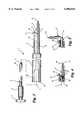
- FIG. 3is an exploded view of the components of the template assembly according to one embodiment of the present invention.
- FIG. 4is an enlarged partial cross-sectional view of the distal tip of the template assembly illustrated in FIG. 3, shown with the guide foot in its initial insertion position.
- FIG. 5is an enlarged partial cross-sectional view of the distal tip as illustrated in FIG. 4, shown with the guide foot in its second deployed position.
- FIG. 6is a partial top elevational view of the distal tip of the template assembly as illustrated in FIG. 4.
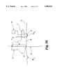
- FIG. 7is a side cross-sectional view of the guide foot.
- FIG. 8is an end elevational view of the proximal end of the guide foot.
- FIG. 9is a side elevational view of the guide foot.
- FIG. 10is an end elevational view of the distal end of the guide foot.
- FIGS. 11a-11bare pictorial representations of the template assembly percutaneously inserted into the patient.
- FIGS. 12a-12bare pictorial representations of the template assembly as the guide foot is being deployed.
- FIGS. 13a-13bare pictorial representations of the template assembly with the guide foot fully deployed.
- FIG. 14is an enlarged pictorial representation of the template assembly anchored to the disc and showing the use of an electrocautery instrument in connection with the deployed guide foot for marking the disc annulus.
- FIG. 15is a side elevational view of another embodiment of the template assembly in which the guide foot carries an electrocautery projection for marking the disc annulus.
- FIG. 16is an enlarged pictorial representation of a template assembly anchored to the disc showing an alternative embodiment of the deployment shaft and guide wire.
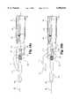
- FIGS. 17a-17bare partial views of the side and top of another embodiment of the template assembly.
- FIGS. 17c and 17dare enlarged partial fragmented cross sectional views of the distal tip of the template assembly illustrated in FIGS. 17a and 17b shown with the guide foot in its initial insertion position and second deployed position respectively.
- FIGS. 17e-17gare enlarged partial cross sectional views of the distal tip of the template assembly illustrated in FIGS. 17a-17d with slightly different guide foot operating details, showing top and side views of the guide foot in its initial insertion position and a side view of the guide foot in its second deployed position.
- FIG. 18ais an enlarged partial fragmented cross sectional view of another embodiment of the distal tip of the template assembly illustrated in FIGS. 17a-17g, wherein the guide foot has a bend and is in its initial insertion position.
- FIG. 18bis an enlarged partial fragmented cross sectional view of the distal tip of the template assembly illustrated in FIG. 18b, shown with the guide foot in its second deployed position.
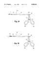
- FIG. 19is a fragmented elevational view of another embodiment of the template assembly wherein the tip portion of the guide foot is shown sectioned.
- FIG. 20is a fragmented elevational view of another embodiment of the template assembly of FIG. 19 wherein the tip portion is shown sectioned and the guide foot has a bend in it.
- the template assembly 15includes an outer tubular body 17, an inner deployment shaft 19 and a guide foot 21.
- the tubular body 17is elongated along a longitudinal axis L between its proximal end 22 and its distal end 23.
- the proximal end 22is disposed outside the skin of the patient while the distal end 23 is situated adjacent the disc annulus of the affected motion segment.
- the tubular body 17defines a central bore 24 from end to end to slidably receive the deployment shaft 19.
- the central bore 24includes a threaded bore 26.
- the proximal portion 27is larger than the distal portion 29 of the tubular body 17, primarily to provide a smaller profile in the region of the vertebrae.
- the larger diameter of the proximal portion 27provides a better grip for the spinal surgeon manipulating the template assembly 15 in situ.
- the deployment shaft 19includes an elongated probe 30 configured to project beyond the distal end 23 of the tubular body 17 and having a generally rounded or blunt tip 31 for reasons set forth below.
- a threaded portion 32having threads that mate with the threaded bore 26 of the tubular body 17.
- the proximal end of the deployment shaftis configured into a handle or knob 34 adapted to facilitate rotation of the deployment shaft 19 within the tubular body 17.
- the knob 34is preferably circular with knurling or other gripping feature defined on the circumference of the knob facilitate manual rotation of the knob.
- the guide foot 21includes a hinge portion 38 and a guide portion 45, with the portions preferably oriented at right angles so that the guide foot takes on the shape of an "L", as seen in FIG. 7.
- the hinge portion 38 of the guide footdefines a hinge boss 39 that is disposed between a pair of hinge flanges 28 projecting from the distal end 23 of the tubular body 17, as best seen in FIGS. 4 and 6.
- a hinge pin 42passes through bores in the hinge flanges 28 and a hinge bore 40 defined in the hinge boss 39 of the guide foot.
- the hinge portion 38 of the guide foot 21defines a proximal face 43 that is closely adjacent the distal end 23 of the tubular body when the guide foot is in its first retraced position shown in FIGS. 3-4. In this first position the axis A of the guide portion 45 of the guide foot is aligned with the longitudinal axis L of the tubular body.
- the guide foot 21, and particularly the hinge portion 38is circular in profile, as depicted in FIG. 8, with an effective outer diameter substantially equal to or less than the outer diameter of the tubular body 17.
- the guide foot 21presents a profile that is no larger than the tubular body, which is a beneficial feature for percutaneous introduction of the template assembly 15.
- the guide portion 45 of the guide footalso includes a tapered tip 46 at its distal end 44 to reduce the risk of trauma to the tissue at the surgical site during introduction of the template assembly.
- the guide foot 21is pivotably connected to the tubular body 17 at the hinge 37.
- the hinge 37is offset to one side of the tubular body to take advantage of the "L" shape of the guide foot 21.
- the guide foot 21initially assumes its first position, shown in FIGS. 3-4, in which the axis A of the guide portion 45 of the guide foot is aligned with, and preferably parallel to, the longitudinal axis L of the tubular body 17.
- the guide foot 21is pivotable to its second deployed position in which the axis A of the foot is at an angle, preferably perpendicular, to the longitudinal axis L, as shown in FIG. 5.
- the guide foot 21is pushed from the first position of FIG. 4 to the second position of FIG. 5 by the rounded tip 31 of the elongated probe 30.
- the guide portion 45 of the guide foot 21includes a guide bore 48 defined therethrough.
- the guide bore 48is sized to receive the working tip of a marking instrument.
- the marking instrumentis an electrocautery instrument that cauterizes the disc annulus.
- the marking instrumentmust be capable of leaving a mark on the annulus sufficient to be visually observed by the spinal surgeon. This mark will identify the proper position for inserting an implant into the disc space.
- the annuluswill be fenestrated at the mark in order to receive an interbody fusion device, such as the device described above.
- Steps in the use of the template assembly 15are depicted in FIGS. 11a-13b.
- the patient's skin Sis punctured to receive a sealed trocar 50.
- the trocar 50optimally provides a working channel for the template assembly 15, as well as for diskectomy instrumentation, fusion devices and insertion instrumentation to be used subsequently.
- One significant advantage achieved by the template assembly 15 according to this inventionis that it is well suited for use in percutaneous endoscopic procedures. It has been found that diskectomies and even fusions can be performed using minimally invasive techniques, without the necessity of the more difficult and invasive surgical procedures of the past.
- the template assembly 15With the sealed trocar 50 anchored to the skin S, the template assembly 15 is introduced with the guide foot 21 in its first position, as depicted in FIG. 11b.
- the deployment shaft 19is retracted within the tubular body 17 during this step so that the rounded tip 31 does not project beyond the distal end 23 of the body.
- the template assembly 15is withdrawn slightly to allow the guide foot to be pushed and pivoted to its second position.
- the deployment shaft 19is advanced through the tubular body 17 by rotating the knob 34 in the direction R shown in FIG. 12a.
- the knob 34 and deployment shaft 19is rotated, the probe 30 bears against the proximal face 43 of the guide foot 21 to cause the foot to pivot about the hinge 37.
- the guide footpivots progressively through the position shown in FIG. 12b to its second fully deployed position shown in FIG. 13b.
- the template assembly 15With the guide foot 21 in its second position, the template assembly 15 is advanced toward the disc until the bottom surface 49 of the foot is against the disc annulus D.
- the deployment shaft 19can be removed and replaced with a guide wire 55, as shown in FIG. 14.
- the guide wirehas a sharp tip to pierce the disc annulus D and may include means to limit and control advancement of the guide wire into the disc.
- the guide wireis advanced into the disc a sufficient distance to effectively anchor the template assembly 15 in position with the guide foot 21 in contact with the annulus D.
- An electrocautery instrument 60is then introduced to the surgical site so that the working tip 61 extends through the guide bore 48 in the guide foot 21.
- the working tip 61is energized to cauterize the disc annulus D leaving a mark M R on the annulus.
- This mark M Ris visible to the surgeon to identify the proper location for insertion of an implant into the disc space.
- the entire template assembly 15can be pivoted about the guide wire in the direction T shown in FIG. 14.
- the guide foot 21is then oriented on the left side of the guide wire, on the opposite side of the disc from the first mark M R .
- a second mark M Lcan then be made on the disc annulus D using the electrocautery instrument.
- the guide wirecan be withdrawn, followed by the template assembly 15. As the assembly is withdrawn from the surgical site, the surrounding tissue bears against the guide foot 21 to cause it to pivot about the hinge 37 and return to its first low-profile position.
- the guide foot 21'is modified from the foot 21 shown in FIG. 14. Specifically, the guide bore 48 is eliminated in favor of an electrocautery projection 25' formed in the bottom surface 49' of the guide foot.
- An electrical attachment 31'provides electrical energy to the guide foot 21'.
- the guide foot 21'is formed of an electrically conductive material and the projection 25' is configured to emulate the working tip of an electrocautery instrument.
- One benefit of this configurationis that it is not necessary to introduce a separate electrocautery instrument to the surgical site.
- the components of the template assembly 15are sized for percutaneous introduction to the disc.
- the assemblyhas an overall length of 12.5 in. (31.75 cm) from the proximal end 22 of the tubular body 17 to the distal end 44 of the guide foot 21 in its retracted first position.
- the tubular body 17has an outer diameter in the specific embodiment of about 0.437 in. (1.11 cm) at the proximal portion 27 and of about 0.250 in. (0.63 cm) at the distal portion 29.
- the central bore 24 of the tubular body 17has a diameter of 0.125 in. (0.32 cm), while the deployment shaft has a diameter of 0.120 in. (0.30 cm) to be slidably disposed within the central bore.
- the mating threads between the deployment shaft 19 and the tubular body 17are preferably 1/4-20 UNC-2B threads.
- the guide foot 21has an effective outer diameter of 0.250 in. (0.63 cm) and a length from proximal face 43 to the distal end 44 of 0.541 in. (1.37 cm).
- the guide bore 48has a diameter of 0.136 in. (0.35 cm) with its center being located 0.313 in. (0.80 cm) from the proximal face 43.
- the distance to the center of the guide bore 48establishes the spacing between the two marks M R and M L made on the disc annulus D to identify the location for insertion of the fusion implants. Referring again to FIG. 14, it can be seen that the mark M R is made at predetermined distance from the guide wire 55 anchored in the disc.
- the mark M Lis separated from the mark M R by twice that predetermined distance. This distance between marks is determined by the necessary separation between the interbody fusion devices to be introduced into the intradiscal space.
- the fusion devicesmay have a maximum diameter of about 0.787 in. (2.00 cm), which requires the two marks M R and M L to be at least that distance apart.
- the template assemblyis configured to mark the location for insertion of two bilateral fusion devices in the lower lumbar spine.
- the dimensions of the guide foot 21 and the guide bore 48, or cauterizing projection 25'will be reduced in accordance with the geometry of the spinal anatomy at the affected motion segment.
- the template assemblycan be configured to provide guide marks for the implantation of more than two fusion devices. In procedures involving three or more such devices, the template assembly can be oriented over successively made marks with the guide wire anchored into the disc at the marks. New marks can be made in the described fashion by pivoting the template assembly about the guide wire. The distance to the center of the guide bore 48 or cauterization projection 25' would be reduced accordingly.
- FIG. 16Two embodiments of the invention have been illustrated and described in detail in the foregoing description and accompanying drawings. Other embodiments are shown in FIG. 16 and following.
- the template assembly 15has been described as used with a separate guide wire 55 to anchor and orient the assembly during the marking steps.
- the deployment shaft 19was required to be removed to accommodate the guide wire 55.
- the deployment shaftcan be cannulated to receive the guide wire therethrough.
- the deployment shaft 19'need not be removed.
- the rounded tip 31 of the deployment shaftwill not traumatize the disc annulus.
- the diameter of the deployment shaftis sufficient to accept a thin guide wire.
- the guide foot 21has been described and depicted as having an "L" shape. Other configurations are contemplated by this invention, provided that the guide bore or cauterization projection can be maintained at the predetermined distances discussed above.
- the componentsare contemplated to be formed from surgical grade stainless steel or other medically suitable material.
- the guide footcan be composed of a plastic material to minimize heat conduction from the working tip of the electrocauterization instrument.
- the devicemay be fabricated of a radioluscent plastic or composite material to allow unimpeded viewing of the guide wire placement and anatomical orientation.
- Other suitable materials for the components of the template assembly 15are contemplated.
- Template assembly 100has outer tubular body 101 extending along a longitudinal axis B between its proximal end 103 and its distal end 104.
- a yoke assembly 120is fixed to the distal end 104 of the body 101.
- a round spike 110 with a tip 116is fixed to the distal end 135 of the yoke assembly and extends along the longitudinal axis B of the tubular body 101.
- Spike 110may be integrally formed with distal end 135 of the yoke assembly.
- spike 110has external threading 136 which mates with internal threading 136' formed in the distal end 135 of the yoke assembly.
- Guide foot 111has a tip 117, preferably tapered, extends generally in the longitudinal direction away from distal end 104 of the tubular body 101.
- the guide foot 111is connected to a cam 113 which sits on a pivot pin 112.
- Guide foot 111may be integrally formed with cam 113 or it may be affixed by a bolt, screw, adhesive or other means known in the art.
- the cam 113can turn on the axis of the pivot pin 112 upon which it sits.
- the cam 113has notch 113n engaged by lug 114p of a driver 114 which is fixed to the end of drive rod 115.
- Drive rod 115may be solid or a hollow tubular structure.
- the proximal portion of drive rod 115is threadedly engaged with a threaded insert 153 (see FIG. 17a) fixed within thumb wheel 152 rotatably mounted in the handle 150. Because of the threaded connection, rotation of wheel 152 causes drive rod 115 to retract relative to the outer tubular body 101 and the yoke, thus causing driver 114 to turn cam 113 on its pivot axis, causing guide foot 111 to pivot outward.
- Handle 150is affixed to outer tubular body 101 by means of a flush port assembly 130 which has a recess receiving end affixed and sealed to the proximal end of the tubular body 101.
- the flush port assembly 130has a tubular post 106 received in a hole in the front portion of the handle and fixed to it by a set screw 151.
- the guide foot 111is kept from pivoting beyond a predetermined maximum radial distance of a circle centered on the spike 110, by a stop wall 121 in a recess in the yoke 120 and a stop lug 123 on the cam 113.
- the driver 114has a notch 122 cut therein which is sized to receive the cam portion of the guide foot 111 and angled so that guide foot 111 and cam 113 are engaged and pivoted by movement of driver 114 (see FIGS. 17e-g).
- the lug 123 on cam 113engages stop wall 121 of the yoke 120 and prevents cam 113 from pivoting past an angle such that tip 117 of guide foot 111 is more than the predetermined maximum distance from spike 110.
- the stop wall 121may be located in various different embodiments so that the tip 117 of guide foot 111 has a predetermined maximum distance of 0.378 inches, 0.416 inches or 0.457 inches.
- the wheel 152is preferably circular with knurling or other gripping features defined on the circumference of the wheel to facilitate manual rotation of the wheel.
- Flush port assembly 130is used to irrigate the site being marked.
- Flush port assembly 130consists of passageway 131 for flushing irrigants through the interior of outer tubular body 101 from the proximal end 103 to the distal end 104 and out through the yoke assembly.
- Flush port assembly 130also includes a flush port cap 132 which is removable. When flush port cap 132 is on the flush port assembly 130, it prevents irritants from entering the passageway and gaining access to the site being marked.
- a handle cap 154At the end of handle 150 most distant from the proximal end 103, is a handle cap 154 with a circular hole in the center through which cautery post 155 or other electrical conducting means passes. Suitable conducting path to the foot 111 is achieved by the materials of the assembly. An insulating coating is provided on the outside of the yoke, tubular body, flush port assembly, handle and, if not otherwise managed, on the thumbwheel too.
- the guide foot 111is straight. In this embodiment when the patient's skin is penetrated by the distal end of template assembly tip 117 of guide foot 111 is adjacent to spike 110, and, because the foot is straight, guide foot 111 is generally parallel to spike 110.
- the tubular body, flush port assembly 130 and handle 150can be the same as in FIGS. 17a-17g, but guide foot 111' has a bend in it. This bend is configured so that when guide foot 111' is pivoted away from spike 110, there will be one particular distance separating spike 110 from tip 117 of guide foot 111' where an axis defined by the bend and tip 117 will be generally parallel to spike 110. This is demonstrated in FIG. 18b where cam 113 has been rotated to pivot guide foot 111' to the point where the axis defined by the bend and tip 117 is generally parallel to the longitudinal axis B along which spike 110 extends.
- Steps in the use of the template assembly 100are similar to those depicted in FIGS. 11a-13b.
- the patient's skinis punctured to receive a sealed trocar 50.
- the template assembly 100With the sealed trocar 50 anchored to the skin S, the template assembly 100 is introduced with the guide foot 111 in its first position, where tip 117 of guide foot 111 is adjacent to spike 110.
- Spike 110is advanced toward the disc until the tip 116 of the spike 110 is against the disc annulus D.
- the location of the spike 110 precisely centered with respect to the desired fusion implant sites in the discis determined, then the disc is pierced with the spike 110 to anchor the assembly to the disc.
- the template assembly 100may then be withdrawn slightly or left in place and guide foot 111 is pivoted to its second position.
- the drive rod 115is retracted through the tubular body 101 by rotating the wheel 152. As the wheel 152 is rotated, drive rod 115 retracts causing driver 114 to turn cam 113 to which guide foot 111 is attached. The tip 117 of guide foot 111 pivots away from the longitudinal axis B and spike 110 as in FIG. 17d and FIG. 18b. It is understood that alternative embodiments in which drive rod 115 and driver 114 are advanced, instead of retracted, are within the scope of the invention.
- the wheel 152is provided with markings to indicate the tip 117 location on a radius of a circle centered on the longitudinal axis B.
- the distance the tip 117 movesis known and can be continuously varied from a distance of zero when adjacent to spike 111 to the full extension as constrained by the predetermined maximum distance allowed for by yoke 120 and stop wall 121.
- the wheelmay be locked into position by, for instance, a second set screw.
- the wheel 152is rotated until the guide foot 111 is constrained from pivoting any further by lug 123 and stop wall 121.
- the predetermined maximum distance allowed for by various stops 121is set at a distance corresponding to typical implant sizes.
- FIGS. 19 and 20two other embodiments of template assembly are shown. Like elements are labeled as previously in FIGS. 17a-g and 18a-b.
- the deployment meansare altered in that instead of wheel 152, handles 200 and 201 are used to control the amount drive rod 115 moves forward.
- Handle 201is fixed to tubular body 101 as is the flush port assembly in FIGS. 17a-e.
- Handle 200is pivotably connected to handle 201 at pivot pin 202 and is pinned to the proximal end of drive rod 115.
- handles 200 and 201may be closed along a full continuum of distances in which the tip 117 moves.
- a bar 210extends from handle 200 and a corresponding bar 211 extends from handle 201.
- Bars 210 and 211have interlocking jaws or ratchets 212. These ratchets are configured so that a predetermined amount of pivoting occurs resulting in the known distances between tip 117 of guide foot 111 and the central longitudinal axis B.
- the bars 210 and 211have three stops or ratchets.
- the stopsare preferably configured so that the tip 117 pivots outward a distance of 0.378 inches at the first ratchet, 0.416 inches at the second ratchet, and 0.457 inches at the third ratchet.
- the central difference between the embodiments in FIGS. 19 and 20is that in FIG. 19 guide foot 111 is sraight and in FIG. 20 guide foot 111' has a bend in it.
- the remainder of the templateis labeled and functions like the embodiments described in FIGS. 17a-g and 18a-b.
- a yoke 120, stop 121 and lug 123could also be used with the handle deployment means in combination with the ratchets or the continuous mode of operation of the handles described.
- the handlescould be configured with just one stop or ratchet corresponding to a desired distance. In this case, a different instrument would have to be used for each size or distance required between tip 117 and spike 110. It is contemplated as within the scope of the invention that a flush port assembly 130 may be used in this embodiment, along with all other embodiments previously described.
- the guide footis formed of an electrically conductive material and the tip is configured to emulate the working tip of an electrocautery instrument.
- the guide foot, cam, driver, and drive rodmay all be formed of conductive material so that when an electrical source is attached to cautery post 155, electrical energy flows through to the guide foot.
- an electrical attachment passing through tubular bodymay provide electrical energy to guide foot 111, 111'.
- the templatecan be used to mark the location for insertion of various instruments and tools into the disc space.
- Other uses for the template assembly of the present inventionmay readily present themselves to persons of ordinary skill in this art.
Landscapes
- Health & Medical Sciences (AREA)
- Engineering & Computer Science (AREA)
- Life Sciences & Earth Sciences (AREA)
- Surgery (AREA)
- Biomedical Technology (AREA)
- Veterinary Medicine (AREA)
- Heart & Thoracic Surgery (AREA)
- Public Health (AREA)
- Animal Behavior & Ethology (AREA)
- General Health & Medical Sciences (AREA)
- Medical Informatics (AREA)
- Nuclear Medicine, Radiotherapy & Molecular Imaging (AREA)
- Molecular Biology (AREA)
- Otolaryngology (AREA)
- Physics & Mathematics (AREA)
- Plasma & Fusion (AREA)
- Oral & Maxillofacial Surgery (AREA)
- Orthopedic Medicine & Surgery (AREA)
- Neurology (AREA)
- Vascular Medicine (AREA)
- Transplantation (AREA)
- Cardiology (AREA)
- Pathology (AREA)
- Prostheses (AREA)
- Surgical Instruments (AREA)
Abstract
Description
Claims (21)
Priority Applications (12)
| Application Number | Priority Date | Filing Date | Title |
|---|---|---|---|
| US08/427,432US5645549A (en) | 1995-04-24 | 1995-04-24 | Template for positioning interbody fusion devices |
| EP96302029AEP0739614A1 (en) | 1995-04-24 | 1996-03-25 | Template for positioning interbody fusion devices |
| CA002172682ACA2172682A1 (en) | 1995-04-24 | 1996-03-26 | Template for positioning interbody fusion devices |
| ZA962811AZA962811B (en) | 1995-04-24 | 1996-04-09 | Template for positioning interbody fusion devices |
| TR96/00332ATR199600332A1 (en) | 1995-04-24 | 1996-04-22 | Template for replacing boiling tools for body use. |
| CN96108944ACN1150011A (en) | 1995-04-24 | 1996-04-23 | Template for positioning interbody fusion devices |
| NO961612ANO961612L (en) | 1995-04-24 | 1996-04-23 | Template for placing fusion devices in the body |
| AU50852/96AAU5085296A (en) | 1995-04-24 | 1996-04-23 | Template for positioning interbody fusion devices |
| JP10284996AJP3728010B2 (en) | 1995-04-24 | 1996-04-24 | Template assembly |
| US09/111,203US6096044A (en) | 1995-04-24 | 1998-07-07 | Template assembly for facilitating the placement of interbody fusion devices |
| AU48641/99AAU4864199A (en) | 1998-07-07 | 1999-07-07 | Template for positioning interbody fusion devices |
| PCT/US1999/015291WO2000001293A2 (en) | 1998-07-07 | 1999-07-07 | Template for marking interbody fusion device implantation locations |
Applications Claiming Priority (3)
| Application Number | Priority Date | Filing Date | Title |
|---|---|---|---|
| US08/427,432US5645549A (en) | 1995-04-24 | 1995-04-24 | Template for positioning interbody fusion devices |
| US08/889,473US5785707A (en) | 1995-04-24 | 1997-07-08 | Template for positioning interbody fusion devices |
| US09/111,203US6096044A (en) | 1995-04-24 | 1998-07-07 | Template assembly for facilitating the placement of interbody fusion devices |
Related Parent Applications (1)
| Application Number | Title | Priority Date | Filing Date |
|---|---|---|---|
| US08/889,473Continuation-In-PartUS5785707A (en) | 1995-04-24 | 1997-07-08 | Template for positioning interbody fusion devices |
Publications (1)
| Publication Number | Publication Date |
|---|---|
| US6096044Atrue US6096044A (en) | 2000-08-01 |
Family
ID=27667940
Family Applications (2)
| Application Number | Title | Priority Date | Filing Date |
|---|---|---|---|
| US08/427,432Expired - LifetimeUS5645549A (en) | 1995-04-24 | 1995-04-24 | Template for positioning interbody fusion devices |
| US09/111,203Expired - LifetimeUS6096044A (en) | 1995-04-24 | 1998-07-07 | Template assembly for facilitating the placement of interbody fusion devices |
Family Applications Before (1)
| Application Number | Title | Priority Date | Filing Date |
|---|---|---|---|
| US08/427,432Expired - LifetimeUS5645549A (en) | 1995-04-24 | 1995-04-24 | Template for positioning interbody fusion devices |
Country Status (9)
| Country | Link |
|---|---|
| US (2) | US5645549A (en) |
| EP (1) | EP0739614A1 (en) |
| JP (1) | JP3728010B2 (en) |
| CN (1) | CN1150011A (en) |
| AU (1) | AU5085296A (en) |
| CA (1) | CA2172682A1 (en) |
| NO (1) | NO961612L (en) |
| TR (1) | TR199600332A1 (en) |
| ZA (1) | ZA962811B (en) |
Cited By (34)
| Publication number | Priority date | Publication date | Assignee | Title |
|---|---|---|---|---|
| US6520967B1 (en)* | 1999-10-20 | 2003-02-18 | Cauthen Research Group, Inc. | Spinal implant insertion instrument for spinal interbody prostheses |
| US6723133B1 (en) | 1998-09-11 | 2004-04-20 | C. R. Bard, Inc. | Performed curved prosthesis having a reduced incidence of developing wrinkles or folds |
| US20040082958A1 (en)* | 2001-03-01 | 2004-04-29 | Michelson Gary K. | Dynamic guard and method for use thereof |
| US6740122B1 (en) | 1998-09-11 | 2004-05-25 | C. R. Bard, Inc. | Preformed curved prosthesis that is adapted to the external iliac vessels |
| US20040153062A1 (en)* | 2003-02-04 | 2004-08-05 | Mcginley Shawn E. | Surgical navigation instrument useful in marking anatomical structures |
| US20040173005A1 (en)* | 2003-03-07 | 2004-09-09 | Martone Christopher James | Self-contained portable air pressure decay test apparatus |
| US20050004578A1 (en)* | 1999-08-18 | 2005-01-06 | Lambrecht Gregory H. | Apparatus delivery in an intervertebral disc |
| US20050177159A1 (en)* | 2001-06-27 | 2005-08-11 | Guzman Pamela C. | Minimally invasive orthopaedic apparatus and methods |
| US20050216085A1 (en)* | 2001-02-04 | 2005-09-29 | Michelson Gary K | Method for using lordotic guard with moveable extensions for creating an implantation space posteriorly in the lumbar spine |
| US20070213739A1 (en)* | 2001-03-01 | 2007-09-13 | Sdgi Holdings, Inc. | Method for using dynamic lordotic guard with movable extensions for creating an implantation space posteriorly in the lumbar spine |
| US20070288031A1 (en)* | 2002-09-04 | 2007-12-13 | Dreyfuss Peter J | Offset drill guide and arthroscopic method |
| US20080039839A1 (en)* | 2005-02-23 | 2008-02-14 | Pioneer Laboratories, Inc. | Minimally invasive surgical system |
| US7500978B2 (en) | 2003-06-20 | 2009-03-10 | Intrinsic Therapeutics, Inc. | Method for delivering and positioning implants in the intervertebral disc environment |
| US7507243B2 (en) | 1999-08-18 | 2009-03-24 | Gregory Lambrecht | Devices and method for augmenting a vertebral disc |
| US7513911B2 (en) | 1999-08-18 | 2009-04-07 | Intrinsic Therapeutics, Inc. | Method of implanting dynamically stable spinal implant |
| US7524333B2 (en) | 1999-08-18 | 2009-04-28 | Intrinsic Therapeutics, Inc. | Method of anchoring an implant in an intervertebral disc |
| US20090157081A1 (en)* | 2007-12-17 | 2009-06-18 | Bradley Michael Homan | Surgical Drill For Providing Holes At An Angle |
| US7553329B2 (en) | 1999-08-18 | 2009-06-30 | Intrinsic Therapeutics, Inc. | Stabilized intervertebral disc barrier |
| US7569061B2 (en) | 2004-11-16 | 2009-08-04 | Innovative Spinal Technologies, Inc. | Off-axis anchor guidance system |
| US7637952B2 (en) | 2002-03-11 | 2009-12-29 | Zimmer Spine, Inc. | Instrumentation and procedure for implanting spinal implant devices |
| US7727241B2 (en) | 2003-06-20 | 2010-06-01 | Intrinsic Therapeutics, Inc. | Device for delivering an implant through an annular defect in an intervertebral disc |
| US20100312279A1 (en)* | 2006-08-23 | 2010-12-09 | Gephart Matthew P | Minimally Invasive Surgical System |
| US7905907B2 (en) | 2003-10-21 | 2011-03-15 | Theken Spine, Llc | Internal structure stabilization system for spanning three or more structures |
| US7959679B2 (en) | 1999-08-18 | 2011-06-14 | Intrinsic Therapeutics, Inc. | Intervertebral anulus and nucleus augmentation |
| US7972337B2 (en) | 2005-12-28 | 2011-07-05 | Intrinsic Therapeutics, Inc. | Devices and methods for bone anchoring |
| US8231678B2 (en) | 1999-08-18 | 2012-07-31 | Intrinsic Therapeutics, Inc. | Method of treating a herniated disc |
| US8323341B2 (en) | 2007-09-07 | 2012-12-04 | Intrinsic Therapeutics, Inc. | Impaction grafting for vertebral fusion |
| US8454612B2 (en) | 2007-09-07 | 2013-06-04 | Intrinsic Therapeutics, Inc. | Method for vertebral endplate reconstruction |
| US8480715B2 (en) | 2007-05-22 | 2013-07-09 | Zimmer Spine, Inc. | Spinal implant system and method |
| US9655665B2 (en) | 2007-07-03 | 2017-05-23 | Pioneer Surgical Technology, Inc. | Bone plate systems |
| US10159514B2 (en) | 2011-12-23 | 2018-12-25 | Pioneer Surgical Technology, Inc. | Method of implanting a bone plate |
| US10226291B2 (en) | 2007-07-03 | 2019-03-12 | Pioneer Surgical Technology, Inc. | Bone plate system |
| US11413129B2 (en) | 2020-06-19 | 2022-08-16 | Davol Inc. | Implantable prosthesis |
| US11877779B2 (en) | 2020-03-26 | 2024-01-23 | Xtant Medical Holdings, Inc. | Bone plate system |
Families Citing this family (57)
| Publication number | Priority date | Publication date | Assignee | Title |
|---|---|---|---|---|
| US6245072B1 (en) | 1995-03-27 | 2001-06-12 | Sdgi Holdings, Inc. | Methods and instruments for interbody fusion |
| US5645549A (en)* | 1995-04-24 | 1997-07-08 | Danek Medical, Inc. | Template for positioning interbody fusion devices |
| US6416515B1 (en) | 1996-10-24 | 2002-07-09 | Spinal Concepts, Inc. | Spinal fixation system |
| EP0934026B1 (en) | 1996-10-24 | 2009-07-15 | Zimmer Spine Austin, Inc | Apparatus for spinal fixation |
| US6045579A (en) | 1997-05-01 | 2000-04-04 | Spinal Concepts, Inc. | Adjustable height fusion device |
| US5928243A (en) | 1997-07-16 | 1999-07-27 | Spinal Concepts, Inc. | Pedicle probe and depth gage |
| US6030389A (en) | 1997-08-04 | 2000-02-29 | Spinal Concepts, Inc. | System and method for stabilizing the human spine with a bone plate |
| US6454769B2 (en) | 1997-08-04 | 2002-09-24 | Spinal Concepts, Inc. | System and method for stabilizing the human spine with a bone plate |
| US5964769A (en) | 1997-08-26 | 1999-10-12 | Spinal Concepts, Inc. | Surgical cable system and method |
| US6053921A (en) | 1997-08-26 | 2000-04-25 | Spinal Concepts, Inc. | Surgical cable system and method |
| US6004326A (en)* | 1997-09-10 | 1999-12-21 | United States Surgical | Method and instrumentation for implant insertion |
| US7776046B2 (en) | 1998-04-09 | 2010-08-17 | Warsaw Orthopedic, Inc. | Method and instrumentation for vertebral interbody fusion |
| US6428541B1 (en) | 1998-04-09 | 2002-08-06 | Sdgi Holdings, Inc. | Method and instrumentation for vertebral interbody fusion |
| US6241729B1 (en)* | 1998-04-09 | 2001-06-05 | Sdgi Holdings, Inc. | Method and instrumentation for posterior interbody fusion |
| ATE274844T1 (en) | 1998-04-09 | 2004-09-15 | Sdgi Holdings Inc | VERTEBRATE BODY DISTRACTOR |
| US6529765B1 (en) | 1998-04-21 | 2003-03-04 | Neutar L.L.C. | Instrumented and actuated guidance fixture for sterotactic surgery |
| US6546277B1 (en)* | 1998-04-21 | 2003-04-08 | Neutar L.L.C. | Instrument guidance system for spinal and other surgery |
| US6298262B1 (en) | 1998-04-21 | 2001-10-02 | Neutar, Llc | Instrument guidance for stereotactic surgery |
| AU4864199A (en) | 1998-07-07 | 2000-01-24 | Sdgi Holdings, Inc. | Template for positioning interbody fusion devices |
| US6351662B1 (en) | 1998-08-12 | 2002-02-26 | Neutar L.L.C. | Movable arm locator for stereotactic surgery |
| US6282437B1 (en) | 1998-08-12 | 2001-08-28 | Neutar, Llc | Body-mounted sensing system for stereotactic surgery |
| US6332887B1 (en) | 1999-04-06 | 2001-12-25 | Benjamin D. Knox | Spinal fusion instrumentation system |
| US6331179B1 (en) | 2000-01-06 | 2001-12-18 | Spinal Concepts, Inc. | System and method for stabilizing the human spine with a bone plate |
| US6514260B1 (en)* | 2000-03-15 | 2003-02-04 | Sdgi Holdings, Inc. | Methods and instruments for laparoscopic spinal surgery |
| KR100371308B1 (en)* | 2000-08-28 | 2003-02-07 | 구자교 | a prosthetic implant for spinal interbody fusion and a inserting apparatus thereof |
| US7766947B2 (en) | 2001-10-31 | 2010-08-03 | Ortho Development Corporation | Cervical plate for stabilizing the human spine |
| US7699849B2 (en)* | 2002-01-17 | 2010-04-20 | Concept Matrix, Llc | Diskectomy instrument with disposable blade head |
| US6726690B2 (en)* | 2002-01-17 | 2004-04-27 | Concept Matrix, Llc | Diskectomy instrument and method |
| US7585301B2 (en)* | 2002-06-12 | 2009-09-08 | Howmedica Osteonics Corp. | Modular hip inserter/positioner |
| USD549344S1 (en) | 2003-01-16 | 2007-08-21 | Concept Matrix, Llc | Diskectomy tool with convex head |
| WO2004105656A1 (en)* | 2003-05-27 | 2004-12-09 | Pentax Corporation | Surgical instrument |
| US7169405B2 (en)* | 2003-08-06 | 2007-01-30 | Warsaw Orthopedic, Inc. | Methods and devices for the treatment of intervertebral discs |
| JP4837026B2 (en)* | 2005-03-21 | 2011-12-14 | カイフォン・ソシエテ・ア・レスポンサビリテ・リミテ | Interspinous process implants with deployable wings and implantation methods |
| US20070100366A1 (en)* | 2005-10-28 | 2007-05-03 | Sara Dziedzic | Minimally invasive tissue expander systems and methods |
| US8642060B2 (en) | 2006-04-24 | 2014-02-04 | Warsaw Orthopedic, Inc. | Controlled release systems and methods for osteal growth |
| US7879027B2 (en) | 2006-04-24 | 2011-02-01 | Warsaw Orthopedic, Inc. | Controlled release devices for fusion of osteal structures |
| US8642059B2 (en)* | 2006-04-24 | 2014-02-04 | Warsaw Orthopedic, Inc. | Controlled release systems and methods for intervertebral discs |
| US7771414B2 (en) | 2006-04-24 | 2010-08-10 | Warsaw Orthopedic, Inc. | Controlled release devices for therapeutic treatments of spinal discs |
| US20080161927A1 (en)* | 2006-10-18 | 2008-07-03 | Warsaw Orthopedic, Inc. | Intervertebral Implant with Porous Portions |
| FR2908978B1 (en)* | 2006-11-28 | 2012-08-03 | Spineart Sa | PROSTHESES HOLDER AND THEIR APPLICATIONS. |
| US7875032B2 (en)* | 2007-04-13 | 2011-01-25 | Warsaw Orthopedic, Inc. | Osteochondral autograft transplantation procedure and apparatus |
| US8956278B2 (en) | 2007-12-21 | 2015-02-17 | Smith & Nephew, Inc. | Multiple portal guide |
| US9826992B2 (en) | 2007-12-21 | 2017-11-28 | Smith & Nephew, Inc. | Multiple portal guide |
| EP3251604B1 (en) | 2010-01-20 | 2020-04-22 | EON Surgical Ltd. | System of deploying an elongate unit in a body cavity |
| US8721539B2 (en)* | 2010-01-20 | 2014-05-13 | EON Surgical Ltd. | Rapid laparoscopy exchange system and method of use thereof |
| US8333807B2 (en)* | 2010-03-05 | 2012-12-18 | Biomet Manufacturing Corp. | Method and apparatus for trialing and implanting a modular femoral hip |
| US8679130B2 (en) | 2010-03-05 | 2014-03-25 | Biomet Manufacturing, Llc | Guide assembly for lateral implants and associated methods |
| US8419743B2 (en)* | 2010-03-05 | 2013-04-16 | Biomet Manufacturing Corp. | Assembly tool for modular implants and associated method |
| US8529569B2 (en) | 2010-03-05 | 2013-09-10 | Biomet Manufacturing, Llc | Method and apparatus for preparing a proximal femur |
| US8460393B2 (en) | 2010-03-05 | 2013-06-11 | Biomet Manufacturing Corp. | Modular lateral hip augments |
| US8221432B2 (en)* | 2010-03-05 | 2012-07-17 | Biomet Manufacturing Corp. | Method and apparatus for implanting a modular femoral hip |
| EP2615980B1 (en) | 2010-09-19 | 2017-08-16 | EON Surgical Ltd. | Micro laparoscopy devices and deployments thereof |
| MX2013003496A (en) | 2010-09-27 | 2013-12-02 | Smith & Nephew Inc | Device and methods for use during arthroscopic surgery. |
| WO2012061639A1 (en) | 2010-11-03 | 2012-05-10 | Smith & Nephew, Inc. | Drill guide |
| US8790352B2 (en)* | 2011-10-03 | 2014-07-29 | Smith & Nephew, Inc. | Ovoid tunnel guide and method of ACL reconstruction |
| CN104644291B (en)* | 2013-11-18 | 2017-12-12 | 宝楠生技股份有限公司 | memory type intervertebral fusion fixation device |
| WO2020092981A1 (en)* | 2018-11-01 | 2020-05-07 | Biocompatibles Uk Limited | Cryoprobe with stiffening element |
Citations (22)
| Publication number | Priority date | Publication date | Assignee | Title |
|---|---|---|---|---|
| US3848601A (en)* | 1972-06-14 | 1974-11-19 | G Ma | Method for interbody fusion of the spine |
| US3964480A (en)* | 1974-10-03 | 1976-06-22 | Froning Edward C | Apparatus for sterotaxic lateral extradural disc puncture |
| US4570624A (en)* | 1983-08-10 | 1986-02-18 | Henry Ford Hospital | Universal guide for inserting parallel pins |
| US4721116A (en)* | 1985-06-04 | 1988-01-26 | Schintgen Jean Marie | Retractable needle biopsy forceps and improved control cable therefor |
| US4772287A (en)* | 1987-08-20 | 1988-09-20 | Cedar Surgical, Inc. | Prosthetic disc and method of implanting |
| US4877020A (en)* | 1984-11-30 | 1989-10-31 | Vich Jose M O | Apparatus for bone graft |
| US4907577A (en)* | 1989-04-03 | 1990-03-13 | Wu Shing Sheng | Spinal transpedicle drill jig |
| US5112336A (en)* | 1991-05-14 | 1992-05-12 | Intermedics Orthopedics, Inc. | Drill guide and template for prosthetic devices |
| US5133720A (en)* | 1990-07-13 | 1992-07-28 | Greenberg Alex M | Surgical drill guide and retractor |
| DE9207031U1 (en)* | 1992-05-21 | 1992-11-05 | Karl Leibinger Medizintechnik GmbH & Co. KG, 7202 Mühlheim | Tubular shaft instrument for minimally invasive surgery (MIC) |
| EP0516494A1 (en)* | 1991-05-31 | 1992-12-02 | MIKROLAND Société Anonyme | Miniaturised forceps medical instrument for celio-surgery |
| US5195505A (en)* | 1990-12-27 | 1993-03-23 | United States Surgical Corporation | Surgical retractor |
| DE9217932U1 (en)* | 1992-04-01 | 1993-06-03 | Rema-Medizintechnik GmbH, 7201 Dürbheim | Endoinstrument |
| WO1994017759A1 (en)* | 1993-02-10 | 1994-08-18 | Spine-Tech, Inc. | Spinal stabilization surgical tool set |
| US5389104A (en)* | 1992-11-18 | 1995-02-14 | Symbiosis Corporation | Arthroscopic surgical instruments |
| US5403312A (en)* | 1993-07-22 | 1995-04-04 | Ethicon, Inc. | Electrosurgical hemostatic device |
| US5489292A (en)* | 1990-10-05 | 1996-02-06 | United States Surgical Corporation | Endoscopic surgical instrument with grip enhancing means |
| US5531744A (en)* | 1991-11-01 | 1996-07-02 | Medical Scientific, Inc. | Alternative current pathways for bipolar surgical cutting tool |
| US5645549A (en)* | 1995-04-24 | 1997-07-08 | Danek Medical, Inc. | Template for positioning interbody fusion devices |
| US5665092A (en)* | 1993-03-01 | 1997-09-09 | Mangiardi; John R. | Marker for surgical procedures |
| US5807393A (en)* | 1992-12-22 | 1998-09-15 | Ethicon Endo-Surgery, Inc. | Surgical tissue treating device with locking mechanism |
| US5810863A (en)* | 1996-06-06 | 1998-09-22 | Moser Medical | Trocar including an obturator with a removable knife |
Family Cites Families (1)
| Publication number | Priority date | Publication date | Assignee | Title |
|---|---|---|---|---|
| FR2662311B1 (en)* | 1990-05-17 | 1992-09-04 | Cetra Sarl | ELECTRIC CONTACT. |
- 1995
- 1995-04-24USUS08/427,432patent/US5645549A/ennot_activeExpired - Lifetime
- 1996
- 1996-03-25EPEP96302029Apatent/EP0739614A1/ennot_activeWithdrawn
- 1996-03-26CACA002172682Apatent/CA2172682A1/ennot_activeAbandoned
- 1996-04-09ZAZA962811Apatent/ZA962811B/enunknown
- 1996-04-22TRTR96/00332Apatent/TR199600332A1/enunknown
- 1996-04-23AUAU50852/96Apatent/AU5085296A/ennot_activeAbandoned
- 1996-04-23CNCN96108944Apatent/CN1150011A/enactivePending
- 1996-04-23NONO961612Apatent/NO961612L/enunknown
- 1996-04-24JPJP10284996Apatent/JP3728010B2/ennot_activeExpired - Fee Related
- 1998
- 1998-07-07USUS09/111,203patent/US6096044A/ennot_activeExpired - Lifetime
Patent Citations (22)
| Publication number | Priority date | Publication date | Assignee | Title |
|---|---|---|---|---|
| US3848601A (en)* | 1972-06-14 | 1974-11-19 | G Ma | Method for interbody fusion of the spine |
| US3964480A (en)* | 1974-10-03 | 1976-06-22 | Froning Edward C | Apparatus for sterotaxic lateral extradural disc puncture |
| US4570624A (en)* | 1983-08-10 | 1986-02-18 | Henry Ford Hospital | Universal guide for inserting parallel pins |
| US4877020A (en)* | 1984-11-30 | 1989-10-31 | Vich Jose M O | Apparatus for bone graft |
| US4721116A (en)* | 1985-06-04 | 1988-01-26 | Schintgen Jean Marie | Retractable needle biopsy forceps and improved control cable therefor |
| US4772287A (en)* | 1987-08-20 | 1988-09-20 | Cedar Surgical, Inc. | Prosthetic disc and method of implanting |
| US4907577A (en)* | 1989-04-03 | 1990-03-13 | Wu Shing Sheng | Spinal transpedicle drill jig |
| US5133720A (en)* | 1990-07-13 | 1992-07-28 | Greenberg Alex M | Surgical drill guide and retractor |
| US5489292A (en)* | 1990-10-05 | 1996-02-06 | United States Surgical Corporation | Endoscopic surgical instrument with grip enhancing means |
| US5195505A (en)* | 1990-12-27 | 1993-03-23 | United States Surgical Corporation | Surgical retractor |
| US5112336A (en)* | 1991-05-14 | 1992-05-12 | Intermedics Orthopedics, Inc. | Drill guide and template for prosthetic devices |
| EP0516494A1 (en)* | 1991-05-31 | 1992-12-02 | MIKROLAND Société Anonyme | Miniaturised forceps medical instrument for celio-surgery |
| US5531744A (en)* | 1991-11-01 | 1996-07-02 | Medical Scientific, Inc. | Alternative current pathways for bipolar surgical cutting tool |
| DE9217932U1 (en)* | 1992-04-01 | 1993-06-03 | Rema-Medizintechnik GmbH, 7201 Dürbheim | Endoinstrument |
| DE9207031U1 (en)* | 1992-05-21 | 1992-11-05 | Karl Leibinger Medizintechnik GmbH & Co. KG, 7202 Mühlheim | Tubular shaft instrument for minimally invasive surgery (MIC) |
| US5389104A (en)* | 1992-11-18 | 1995-02-14 | Symbiosis Corporation | Arthroscopic surgical instruments |
| US5807393A (en)* | 1992-12-22 | 1998-09-15 | Ethicon Endo-Surgery, Inc. | Surgical tissue treating device with locking mechanism |
| WO1994017759A1 (en)* | 1993-02-10 | 1994-08-18 | Spine-Tech, Inc. | Spinal stabilization surgical tool set |
| US5665092A (en)* | 1993-03-01 | 1997-09-09 | Mangiardi; John R. | Marker for surgical procedures |
| US5403312A (en)* | 1993-07-22 | 1995-04-04 | Ethicon, Inc. | Electrosurgical hemostatic device |
| US5645549A (en)* | 1995-04-24 | 1997-07-08 | Danek Medical, Inc. | Template for positioning interbody fusion devices |
| US5810863A (en)* | 1996-06-06 | 1998-09-22 | Moser Medical | Trocar including an obturator with a removable knife |
Cited By (94)
| Publication number | Priority date | Publication date | Assignee | Title |
|---|---|---|---|---|
| US6723133B1 (en) | 1998-09-11 | 2004-04-20 | C. R. Bard, Inc. | Performed curved prosthesis having a reduced incidence of developing wrinkles or folds |
| US6740122B1 (en) | 1998-09-11 | 2004-05-25 | C. R. Bard, Inc. | Preformed curved prosthesis that is adapted to the external iliac vessels |
| US20060217811A1 (en)* | 1999-08-18 | 2006-09-28 | Lambrecht Gregory H | Method of performing a procedure within a disc |
| US7553329B2 (en) | 1999-08-18 | 2009-06-30 | Intrinsic Therapeutics, Inc. | Stabilized intervertebral disc barrier |
| US7563282B2 (en) | 1999-08-18 | 2009-07-21 | Intrinsic Therapeutics, Inc. | Method of supporting nucleus pulposus |
| US9333087B2 (en) | 1999-08-18 | 2016-05-10 | Intrinsic Therapeutics, Inc. | Herniated disc repair |
| US8409284B2 (en) | 1999-08-18 | 2013-04-02 | Intrinsic Therapeutics, Inc. | Methods of repairing herniated segments in the disc |
| US8257437B2 (en) | 1999-08-18 | 2012-09-04 | Intrinsic Therapeutics, Inc. | Methods of intervertebral disc augmentation |
| US7553330B2 (en) | 1999-08-18 | 2009-06-30 | Intrinsic Therapeutics, Inc. | Methods of reinforcing an intervertebral disc annulus |
| US20050004578A1 (en)* | 1999-08-18 | 2005-01-06 | Lambrecht Gregory H. | Apparatus delivery in an intervertebral disc |
| US8231678B2 (en) | 1999-08-18 | 2012-07-31 | Intrinsic Therapeutics, Inc. | Method of treating a herniated disc |
| US8025698B2 (en) | 1999-08-18 | 2011-09-27 | Intrinsic Therapeutics, Inc. | Method of rehabilitating an anulus fibrosus |
| US8002836B2 (en) | 1999-08-18 | 2011-08-23 | Intrinsic Therapeutics, Inc. | Method for the treatment of the intervertebral disc anulus |
| US7717961B2 (en)* | 1999-08-18 | 2010-05-18 | Intrinsic Therapeutics, Inc. | Apparatus delivery in an intervertebral disc |
| US9706947B2 (en) | 1999-08-18 | 2017-07-18 | Intrinsic Therapeutics, Inc. | Method of performing an anchor implantation procedure within a disc |
| US7658765B2 (en) | 1999-08-18 | 2010-02-09 | Intrinsic Therapeutics, Inc. | Resilient intervertebral disc implant |
| US8021425B2 (en) | 1999-08-18 | 2011-09-20 | Intrinsic Therapeutics, Inc. | Versatile method of repairing an intervertebral disc |
| US7998213B2 (en) | 1999-08-18 | 2011-08-16 | Intrinsic Therapeutics, Inc. | Intervertebral disc herniation repair |
| US7959679B2 (en) | 1999-08-18 | 2011-06-14 | Intrinsic Therapeutics, Inc. | Intervertebral anulus and nucleus augmentation |
| US7879097B2 (en)* | 1999-08-18 | 2011-02-01 | Intrinsic Therapeutics, Inc. | Method of performing a procedure within a disc |
| US7867278B2 (en) | 1999-08-18 | 2011-01-11 | Intrinsic Therapeutics, Inc. | Intervertebral disc anulus implant |
| US7749275B2 (en) | 1999-08-18 | 2010-07-06 | Intrinsic Therapeutics, Inc. | Method of reducing spinal implant migration |
| US7507243B2 (en) | 1999-08-18 | 2009-03-24 | Gregory Lambrecht | Devices and method for augmenting a vertebral disc |
| US7513911B2 (en) | 1999-08-18 | 2009-04-07 | Intrinsic Therapeutics, Inc. | Method of implanting dynamically stable spinal implant |
| US7524333B2 (en) | 1999-08-18 | 2009-04-28 | Intrinsic Therapeutics, Inc. | Method of anchoring an implant in an intervertebral disc |
| US6520967B1 (en)* | 1999-10-20 | 2003-02-18 | Cauthen Research Group, Inc. | Spinal implant insertion instrument for spinal interbody prostheses |
| US6814737B2 (en) | 1999-10-20 | 2004-11-09 | Cauthen Research Group, Inc. | Spinal implant insertion instrument for spinal interbody prostheses |
| US20030135220A1 (en)* | 1999-10-20 | 2003-07-17 | Cauthen Joseph C. | Spinal implant insertion instrument for spinal interbody prostheses |
| US20050216085A1 (en)* | 2001-02-04 | 2005-09-29 | Michelson Gary K | Method for using lordotic guard with moveable extensions for creating an implantation space posteriorly in the lumbar spine |
| US7998143B2 (en) | 2001-03-01 | 2011-08-16 | Warsaw Orthopedic, Inc. | Dynamic guard |
| US9211198B2 (en) | 2001-03-01 | 2015-12-15 | Warsaw Orthopedic, Inc. | Method for using a guard for creating a socket posteriorly in the lumbar spine |
| US8372079B2 (en) | 2001-03-01 | 2013-02-12 | Warsaw Orthopedic, Inc. | Dynamic guard and method for use thereof |
| US20050043741A1 (en)* | 2001-03-01 | 2005-02-24 | Michelson Gary K. | Retractor for percutaneous surgery in a patient and method for use thereof |
| US20070213739A1 (en)* | 2001-03-01 | 2007-09-13 | Sdgi Holdings, Inc. | Method for using dynamic lordotic guard with movable extensions for creating an implantation space posteriorly in the lumbar spine |
| US8764755B2 (en) | 2001-03-01 | 2014-07-01 | Warsaw Orthopedic, Inc. | Method for using a guard for creating a socket posteriorly in the lumbar spine |
| US7955360B2 (en)* | 2001-03-01 | 2011-06-07 | Warsaw Orthopedic, Inc. | Method for using dynamic lordotic guard with movable extensions for creating an implantation space posteriorly in the lumbar spine |
| US20040082958A1 (en)* | 2001-03-01 | 2004-04-29 | Michelson Gary K. | Dynamic guard and method for use thereof |
| US7909832B2 (en) | 2001-03-01 | 2011-03-22 | Warsaw Orthopedic, Inc. | Retractor for percutaneous surgery in a patient and method for use thereof |
| US9597202B2 (en) | 2001-03-01 | 2017-03-21 | Warsaw Orthopedic, Inc. | Method for using a guard for creating a socket posteriorly in the spine |
| US20050261555A1 (en)* | 2001-06-27 | 2005-11-24 | Guzman Pamela C | Minimally invasive orthopaedic apparatus and methods |
| US20050177159A1 (en)* | 2001-06-27 | 2005-08-11 | Guzman Pamela C. | Minimally invasive orthopaedic apparatus and methods |
| US8328808B2 (en)* | 2001-06-27 | 2012-12-11 | Biomet, C.V. | Minimally invasive orthopaedic apparatus and methods |
| US7819877B2 (en) | 2001-06-27 | 2010-10-26 | BePuy Products, Inc. | Method and apparatus for endoscopic minimally invasive orthopaedic plating procedures |
| US8845648B2 (en) | 2001-06-27 | 2014-09-30 | Biomet C.V. | Minimally invasive orthopaedic apparatus and methods |
| US7637952B2 (en) | 2002-03-11 | 2009-12-29 | Zimmer Spine, Inc. | Instrumentation and procedure for implanting spinal implant devices |
| US8506573B2 (en)* | 2002-09-04 | 2013-08-13 | Arthrex, Inc. | Offset drill guide and arthroscopic method |
| US20070288031A1 (en)* | 2002-09-04 | 2007-12-13 | Dreyfuss Peter J | Offset drill guide and arthroscopic method |
| EP1854426A1 (en)* | 2003-02-04 | 2007-11-14 | Zimmer Technology, Inc. | Surgical navigation instrument useful in marking anatomical structures |
| US20040153062A1 (en)* | 2003-02-04 | 2004-08-05 | Mcginley Shawn E. | Surgical navigation instrument useful in marking anatomical structures |
| EP1444962A3 (en)* | 2003-02-04 | 2004-09-01 | Zimmer Technology, Inc. | Surgical navigation instrument useful in marking anatomical structures |
| US7458977B2 (en) | 2003-02-04 | 2008-12-02 | Zimmer Technology, Inc. | Surgical navigation instrument useful in marking anatomical structures |
| US20040173005A1 (en)* | 2003-03-07 | 2004-09-09 | Martone Christopher James | Self-contained portable air pressure decay test apparatus |
| US7727241B2 (en) | 2003-06-20 | 2010-06-01 | Intrinsic Therapeutics, Inc. | Device for delivering an implant through an annular defect in an intervertebral disc |
| US7500978B2 (en) | 2003-06-20 | 2009-03-10 | Intrinsic Therapeutics, Inc. | Method for delivering and positioning implants in the intervertebral disc environment |
| US7905907B2 (en) | 2003-10-21 | 2011-03-15 | Theken Spine, Llc | Internal structure stabilization system for spanning three or more structures |
| US7569061B2 (en) | 2004-11-16 | 2009-08-04 | Innovative Spinal Technologies, Inc. | Off-axis anchor guidance system |
| US9730738B2 (en) | 2005-02-23 | 2017-08-15 | Pioneer Surgical Technology, Inc. | Minimally invasive surgical system |
| US20080039839A1 (en)* | 2005-02-23 | 2008-02-14 | Pioneer Laboratories, Inc. | Minimally invasive surgical system |
| US12232782B2 (en) | 2005-02-23 | 2025-02-25 | Xtant Medical Holdings, Inc. | Minimally invasive surgical system |
| US11116553B2 (en) | 2005-02-23 | 2021-09-14 | Pioneer Surgical Technology, Inc. | Minimally invasive surgical system |
| US8192439B2 (en) | 2005-02-23 | 2012-06-05 | Pioneer Surgical Technology, Inc. | Minimally invasive surgical system |
| US10194959B2 (en) | 2005-02-23 | 2019-02-05 | Pioneer Surgical Technology, Inc. | Minimally invasive surgical system |
| US20080039840A1 (en)* | 2005-02-23 | 2008-02-14 | Pioneer Laboratories, Inc. | Minimally invasive surgical system |
| US7918878B2 (en) | 2005-02-23 | 2011-04-05 | Pioneer Surgical Technology, Inc. | Minimally invasive surgical system |
| US7922727B2 (en) | 2005-02-23 | 2011-04-12 | Pioneer Surgical Technology, Inc. | Minimally invasive surgical system |
| US8641719B2 (en) | 2005-02-23 | 2014-02-04 | Pioneer Surgical Technology, Inc. | Minimally invasive surgical system |
| US9033988B2 (en) | 2005-02-23 | 2015-05-19 | Pioneer Surgical Technology, Inc. | Minimally invasive surgical system |
| US9610106B2 (en) | 2005-12-28 | 2017-04-04 | Intrinsic Therapeutics, Inc. | Bone anchor systems |
| US10470804B2 (en) | 2005-12-28 | 2019-11-12 | Intrinsic Therapeutics, Inc. | Bone anchor delivery systems and methods |
| US7972337B2 (en) | 2005-12-28 | 2011-07-05 | Intrinsic Therapeutics, Inc. | Devices and methods for bone anchoring |
| US9039741B2 (en) | 2005-12-28 | 2015-05-26 | Intrinsic Therapeutics, Inc. | Bone anchor systems |
| US8394146B2 (en) | 2005-12-28 | 2013-03-12 | Intrinsic Therapeutics, Inc. | Vertebral anchoring methods |
| US11185354B2 (en) | 2005-12-28 | 2021-11-30 | Intrinsic Therapeutics, Inc. | Bone anchor delivery systems and methods |
| US8114082B2 (en) | 2005-12-28 | 2012-02-14 | Intrinsic Therapeutics, Inc. | Anchoring system for disc repair |
| US8551141B2 (en) | 2006-08-23 | 2013-10-08 | Pioneer Surgical Technology, Inc. | Minimally invasive surgical system |
| US20100312279A1 (en)* | 2006-08-23 | 2010-12-09 | Gephart Matthew P | Minimally Invasive Surgical System |
| US8480715B2 (en) | 2007-05-22 | 2013-07-09 | Zimmer Spine, Inc. | Spinal implant system and method |
| US10226291B2 (en) | 2007-07-03 | 2019-03-12 | Pioneer Surgical Technology, Inc. | Bone plate system |
| US9655665B2 (en) | 2007-07-03 | 2017-05-23 | Pioneer Surgical Technology, Inc. | Bone plate systems |
| US10898247B2 (en) | 2007-07-03 | 2021-01-26 | Pioneer Surgical Technology, Inc. | Bone plate system |
| US9226832B2 (en) | 2007-09-07 | 2016-01-05 | Intrinsic Therapeutics, Inc. | Interbody fusion material retention methods |
| US8454612B2 (en) | 2007-09-07 | 2013-06-04 | Intrinsic Therapeutics, Inc. | Method for vertebral endplate reconstruction |
| US10076424B2 (en) | 2007-09-07 | 2018-09-18 | Intrinsic Therapeutics, Inc. | Impaction systems |
| US10716685B2 (en) | 2007-09-07 | 2020-07-21 | Intrinsic Therapeutics, Inc. | Bone anchor delivery systems |
| US8323341B2 (en) | 2007-09-07 | 2012-12-04 | Intrinsic Therapeutics, Inc. | Impaction grafting for vertebral fusion |
| US8361155B2 (en) | 2007-09-07 | 2013-01-29 | Intrinsic Therapeutics, Inc. | Soft tissue impaction methods |
| US8771273B2 (en)* | 2007-12-17 | 2014-07-08 | Karl Storz Gmbh & Co. Kg | Surgical drill for providing holes at an angle |
| US20090157081A1 (en)* | 2007-12-17 | 2009-06-18 | Bradley Michael Homan | Surgical Drill For Providing Holes At An Angle |
| US10159514B2 (en) | 2011-12-23 | 2018-12-25 | Pioneer Surgical Technology, Inc. | Method of implanting a bone plate |
| US11696786B2 (en) | 2011-12-23 | 2023-07-11 | Pioneer Surgical Technology, Inc. | Instrument for inserting a spinal device |
| US10980575B2 (en) | 2011-12-23 | 2021-04-20 | Pioneer Surgical Technology, Inc. | Instrument for inserting a spinal device |
| US11877779B2 (en) | 2020-03-26 | 2024-01-23 | Xtant Medical Holdings, Inc. | Bone plate system |
| US11413129B2 (en) | 2020-06-19 | 2022-08-16 | Davol Inc. | Implantable prosthesis |
| US12138148B2 (en) | 2020-06-19 | 2024-11-12 | Davol Inc. | Implantable prosthesis |
Also Published As
| Publication number | Publication date |
|---|---|
| AU5085296A (en) | 1996-11-07 |
| JPH0919447A (en) | 1997-01-21 |
| NO961612D0 (en) | 1996-04-23 |
| CA2172682A1 (en) | 1996-10-25 |
| JP3728010B2 (en) | 2005-12-21 |
| CN1150011A (en) | 1997-05-21 |
| EP0739614A1 (en) | 1996-10-30 |
| ZA962811B (en) | 1996-10-14 |
| NO961612L (en) | 1996-10-25 |
| US5645549A (en) | 1997-07-08 |
| TR199600332A1 (en) | 1997-03-21 |
Similar Documents
| Publication | Publication Date | Title |
|---|---|---|
| US6096044A (en) | Template assembly for facilitating the placement of interbody fusion devices | |
| US5785707A (en) | Template for positioning interbody fusion devices | |
| US20240115274A1 (en) | Systems for treating nerves within bone | |
| US20200214762A1 (en) | Denervation methods | |
| US8317838B2 (en) | System and method for minimally invasive posterior fixation | |
| JP4223812B2 (en) | Percutaneous surgical apparatus and method | |
| US9138217B2 (en) | Surgical access system and related methods | |
| US8535309B2 (en) | Vertebral bone channeling systems | |
| JP2000511788A (en) | Percutaneous surgical device and method | |
| US20250072909A1 (en) | Percutaneous discectomy kit and method | |
| WO2000001293A2 (en) | Template for marking interbody fusion device implantation locations | |
| MXPA96001450A (en) | Template for the placement of fusion devices between cuer |
Legal Events
| Date | Code | Title | Description |
|---|---|---|---|
| AS | Assignment | Owner name:SDGI HOLDINGS, INC., TENNESSEE Free format text:ASSIGNMENT OF ASSIGNORS INTEREST;ASSIGNORS:BOYD, LAWRENCE M.;RAY, EDDIE III;REEL/FRAME:009348/0217 Effective date:19980706 | |
| AS | Assignment | Owner name:SDGI HOLDINGS, TENNESSEE Free format text:ASSIGNMENT OF ASSIGNORS INTEREST;ASSIGNOR:MCGAHAN, THOMAS;REEL/FRAME:009647/0458 Effective date:19981123 | |
| AS | Assignment | Owner name:SDGI HOLDINGS, INC. A CORPORATION OF DELAWARE, DEL Free format text:CORRECTIVE ASSIGNMENT TO CORRECT THE ASSIGNEE'S ADDRESS AN ASSIGNMENT WAS PREVIOUSLY RECORDED ON REEL 9348 FRAME 0220;ASSIGNORS:BOYD, LAWRENCE M.;RAY, EDDIE III;MCGAHAN, THOMAS;REEL/FRAME:010478/0804 Effective date:19980706 Owner name:SDGI HOLDINGS, INC., DELAWARE Free format text:CORRCECTIVE ASSIGNMENT TO CORRECT ASSIGNEE'S ADDRESS PREVIOUSLY AT REEL 9647, FRAME 0458.;ASSIGNOR:MCGAHAN, THOMAS;REEL/FRAME:010511/0970 Effective date:19981123 | |
| STCF | Information on status: patent grant | Free format text:PATENTED CASE | |
| FPAY | Fee payment | Year of fee payment:4 | |
| AS | Assignment | Owner name:WARSAW ORTHOPEDIC, INC.,INDIANA Free format text:MERGER;ASSIGNOR:SDGI HOLDINGS, INC.;REEL/FRAME:018573/0086 Effective date:20061201 Owner name:WARSAW ORTHOPEDIC, INC., INDIANA Free format text:MERGER;ASSIGNOR:SDGI HOLDINGS, INC.;REEL/FRAME:018573/0086 Effective date:20061201 | |
| FPAY | Fee payment | Year of fee payment:8 | |
| FPAY | Fee payment | Year of fee payment:12 | |
| AS | Assignment | Owner name:WARSAW ORTHOPEDIC, INC, INDIANA Free format text:CORRECTIVE ASSIGNMENT TO CORRECT T0 REMOVE APPLICATION NUMBER PREVIOUSLY RECORDED AT REEL: 018573 FRAME: 0086. ASSIGNOR(S) HEREBY CONFIRMS THE MERGER;ASSIGNOR:SDGI HOLDINGS, INC.;REEL/FRAME:033904/0891 Effective date:20061201 |