US6095381A - Self-closing seal with a sealing membrane - Google Patents
Self-closing seal with a sealing membraneDownload PDFInfo
- Publication number
- US6095381A US6095381AUS09/029,430US2943098AUS6095381AUS 6095381 AUS6095381 AUS 6095381AUS 2943098 AUS2943098 AUS 2943098AUS 6095381 AUS6095381 AUS 6095381A
- Authority
- US
- United States
- Prior art keywords
- closure
- self
- connecting wall
- head
- closing
- Prior art date
- Legal status (The legal status is an assumption and is not a legal conclusion. Google has not performed a legal analysis and makes no representation as to the accuracy of the status listed.)
- Expired - Lifetime
Links
Images


Classifications
- B—PERFORMING OPERATIONS; TRANSPORTING
- B65—CONVEYING; PACKING; STORING; HANDLING THIN OR FILAMENTARY MATERIAL
- B65D—CONTAINERS FOR STORAGE OR TRANSPORT OF ARTICLES OR MATERIALS, e.g. BAGS, BARRELS, BOTTLES, BOXES, CANS, CARTONS, CRATES, DRUMS, JARS, TANKS, HOPPERS, FORWARDING CONTAINERS; ACCESSORIES, CLOSURES, OR FITTINGS THEREFOR; PACKAGING ELEMENTS; PACKAGES
- B65D47/00—Closures with filling and discharging, or with discharging, devices
- B65D47/04—Closures with discharging devices other than pumps
- B65D47/20—Closures with discharging devices other than pumps comprising hand-operated members for controlling discharge
- B65D47/2018—Closures with discharging devices other than pumps comprising hand-operated members for controlling discharge comprising a valve or like element which is opened or closed by deformation of the container or closure
- B65D47/2031—Closures with discharging devices other than pumps comprising hand-operated members for controlling discharge comprising a valve or like element which is opened or closed by deformation of the container or closure the element being formed by a slit, narrow opening or constrictable spout, the size of the outlet passage being able to be varied by increasing or decreasing the pressure
Definitions
- the inventionrelates to a self-closing closure with a closure cap, with a through-passage opening formed in the closure cap, and with a closure membrane, assigned to the through-passage opening.
- closureshave already been disclosed in various configurations.
- disadvantageshave presented themselves to the effect that either the closure has not been sufficiently reliable or the necessary ventilation requires such a negative pressure that, in the case of conventional squeezable bottles which are provided with a closure, for example, the negative pressure formed is not sufficient or the recovery forces in the squeezable bottle have to be so pronounced that they are not really suitable for conventional usage.
- the inventionis concerned with the technical problem of specifying a self-closing closure which is easier to use.
- the aimis also to achieve a closure which is favorable in terms of production. Furthermore, it is also endeavoured to render installation as favorable as possible.
- the inventionis also concerned with the technical problem of specifying a closure membrane which is advantageous for said closure.
- the closure membranehas a bottom retaining border and a top, essentially concave closure head, the closure head and the retaining border, furthermore, being connected by a connecting wall. It is also preferred for the installed state of the closure membrane to be achieved by turning the closure membrane inside out after it has been produced by injection moulding. This produces favorable force effects.
- the concave closure headis advantageously prestressed into its closed state by radially acting forces of the inside-out connecting wall.
- rapid openingin particular for ventilating purposes, during sucking back, should also be noted.
- the connecting wallmay preferably continue into a constriction beneath a projection area of the closure head, this observation once again being based on the installed state.
- thisis achieved, in particular, in that, in the production state (injection-moulded state), the connecting wall extends essentially cylindrically, starting from the closure head.
- the connecting wallmay also be a variation here in terms of a conical configuration. Continuation into a constriction beneath the projection area of the closure head produces something of a goblet-like configuration of the closure membrane as a whole in this region.
- the connecting walladjoins the bottom of the closure head in an essentially cylindrically extending manner, in particular when the abovementioned operation of turning the closure membrane inside out after production is not carried out.
- the border side of the closure headis of a greater thickness than the boundary wall.
- the closure headmay taper inwards continuously, starting from its border region.
- the boundary wallis attached to a top region of the border edge, as seen in cross-section, of the closure head of the closure membrane--this observation once again being based on the installed state--and the boundary wall grips over a bottom, free border region of the boundary edge of the closure head.
- the resulting prestressing in the structure of the closure membraneensures a high sealing force and, on the other hand, when the structure is disrupted (dispensing operation or sucking back), breaking out also takes place straight away in response to relatively low force exertion.
- the radial opening slitspreferably provided in the closure head open, above a certain pressure, reliably and almost abruptly.
- the connecting wallruns essentially cylindrically.
- the abovedescribed prestressing to which the closure head is subjected in the inside-out state of the closure membrane, or a funnel formationmay also be influenced and varied by a change in the angle in the connecting wall (as seen in cross-section).
- the connecting wallmerges into a peripheral reinforcement region, and a fastening ring is attached to the reinforcement ring.
- the reinforcement ringhas proven to be advantageous, in particular, with respect to the closure membrane moving out telescopically in the event of pressure build-up, as is described in more detail below.
- the fastening ringserves for retaining the closure membrane in the closure.
- the fastening ringis connected to the reinforcement ring via an attachment wall which, in cross-section, extends at an angle to the connecting wall.
- a widened regionto adjoin the through-passage opening, formed in the closure cap, towards the outside, and for the closure head of the closure membrane to be assigned to this widened region.
- the connecting wallcan extend into the widened region. It is not absolutely necessary here for the connecting wall to rest against the widened region in the rest state of the closure. However, the connecting wall usually comes to butt against the widened region during a dispensing operation, this being accompanied by advantageous force conditions, which are described in more detail below, and by the opening operation in the closure head being influenced, usually assisted.
- Arranging the closure head, according to the invention, in the widened regionresults, first of all, in the closure head having a certain amount of support in the downwards direction, but, if appropriate, also in the radially lateral direction.
- the taper provided beneath the closure head by the widened region and the through-passage openingis advantageous in that it provides something of a positively locking seat for the closure membrane. Simple installation of the closure membrane is possible. Adhesive bonding or the like is not necessary. Nevertheless, the closure head has sufficient freedom of movement in order to carry out a discharge operation in an advantageous manner.
- the closure head itselfmay be comparatively thin.
- the concave configuration and the radially inwardly acting support in the widened regionproduce a comparatively high closure force, which reliably makes it possible to achieve full closure of the discharge opening.
- This influencing or assisting of the closure force, and thus also of the opening characteristics of the closure membranemay be provided on its own or in combination with the abovedescribed influencing which can be achieved by turning the closure membrane inside out.
- the closure headmay be designed with slits which, starting from a center point, extend in the radial direction. In the rest state of the closure membrane, the slits are fully closed as a result of the slit-bounding sides pressing against one another.
- the closure headUpon actuation of the container on which such a closure is fitted, the closure head is forced outwards and opening is achieved by the slits gaping open.
- the closure headhas a permanent, central opening, a supporting plate, on which the closure head is seated in a sealing manner in the rest state, being formed beneath the opening, with the result that, in this embodiment too, full closure is achieved in the rest state.
- a supporting plateyou are also referred to German Patent Application 19 51 007, which is not a prior publication, and the international Patent Application PCT/EP95/01104.
- a border beadwhich projects beyond the closure head, is formed in an outer region of the closure head.
- Such a border beadwhich nevertheless does not project beyond the through-passage opening in the rest state, is known it its own right, in a comparable closure membrane from EP-A2 545 678, which was mentioned in the introduction.
- the border beadis arranged in the area of the widened region, and thus outside the through-passage opening.
- the border beadis arranged in the area of the widened region, this means, at the same time, that this bead is turned outwards, and thus is exposed at the top.
- the beadis given support in the downward direction and radial support. This may be utilized, for the purposes of transportation safeguard, to provide a closure cover or the like which acts on the border bead. Securing of the border bead not only obstructs an opening movement of the closure head to a certain extent, but also achieves, in particular, as a result of the flexibility of the material of the closure membrane, advantageous sealing in the transporting state.
- the sealing actionis further enhanced by an increased internal pressure which may possibly arise during transportation if the container is subjected to corresponding pressure.
- a--further--widened regionwhich opens in the opposite direction, directly adjoins the through-passage opening, beneath the latter.
- One or both of the abovementioned widened regionsmay be of essentially conical design. Overall, this produces something of a double rivet-like design of the inserted closure membrane and correspondingly advantageous retention of -he closure membrane in the closure cap.
- a groove-like depressionwhich reaches as far as the through-passage opening is formed in the widened region which adjoins the through-passage opening towards the outside.
- the depressionis preferably formed vertically and/or radially. This permits advantageous ventilation, for the sucking back of air into the container after a discharge operation.
- the airflows through a channel which is formed by the widened region and the through-passage opening and is covered by the connecting wall. It is also possible for corresponding air openings to be formed, as bores or channels, just in the wall of the widened region and of the through-passage opening. The air which has been newly sucked back results in a lifting action in the region of the border bead.
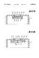
- FIG. 1shows a cross-section through a closure cap with a closure membrane in a first embodiment, the section being taken along line I--I in FIG. 3;
- FIG. 2shows an enlarged illustration of the closure according to FIG. 1;
- FIG. 3shows an illustration of a plan view of the closure according to FIG. 1;
- FIG. 4shows the closure according to FIG. 1 in the discharge state
- FIG. 5shows an illustration of the closure according to FIG. 1 with a transportation safeguard
- FIG. 6shows a cross-sectional illustration through a closure cap with a closure membrane in a further embodiment
- FIG. 7shows an illustration according to FIG. 1, in which a supporting plate is provided
- FIG. 8shows an illustration according to FIG. 5, likewise with a supporting plate
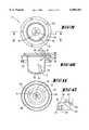
- FIG. 9shows a bottom view of a closure membrane
- FIG. 10shows a section through the closure membrane according to FIG. 9, the section being taken along line X--X in FIG. 9, with an associated installation ring which is illustrated in cross-section;
- FIG. 11shows a plan view of the subject matter of FIGS. 9 and 10;
- FIG. 12shows an enlarged detail from the illustration according to FIG. 10, after assembly with the installation ring;
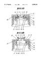
- FIG. 13shows an illustration of the subject matter of FIGS. 9 to 12 installed in a closure, in the non-actuated state
- FIG. 14shows an illustration according to FIG. 13, after an increase in the internal pressure in the container provided with the closure, but before commencement of a dispensing operation;
- FIG. 15shows the closure according to FIG. 13 in the dispensing state
- FIG. 16shows the closure according to FIG. 13 after completion of a dispensing operation and during the sucking back of air
- FIGS. 17 to 20show illustrations corresponding to FIGS. 13 to 16, but for a further installation example
- FIGS. 21 to 23show illustrations corresponding to FIGS. 13 to 16, but for a third installation example
- FIG. 24shows a further installation example, in relation to a tube closure
- FIG. 25shows an illustration according to FIGS. 21 to 23, but with a tamperproof seal
- FIG. 26shows a plan view of the closure in the region of the closure opening after the tamperproof seal and the closure membrane have been removed;
- FIG. 27shows a further embodiment.
- FIG. 1The illustrations and description relate, first of all with reference to FIG. 1, to a self-closing closure with a closure cap 1 and a closure membrane 2, only part of the closure cap 1 being illustrated. Furthermore, the closure cap 1 is part of a container which can be compressed in order to discharge fluid contents--this not being illustrated specifically.
- the closure membrane 2has a bottom, peripheral retaining border 3, a connecting wall 4, which essentially extends upwards from the retaining border 3, and a top closure head 5. Slits 6, 7 which extend radially from a centre point are formed in the closure head 5 (see also FIG. 3).
- the essential factoris that the closure cap 1 forms a through-passage opening 8, which widens outwards in the form of a widened region 9.
- the through-passage opening 8can be seen in the narrowest region of the discharge opening as a whole.
- the connecting wall 4passes through the through-passage opening 8 and, during actuation at any rate, is supported radially in the widened region 9.
- the connecting wall 4merges, via an attachment curve, which forms a top, peripheral border bead 10, into the closure head 5.
- the closure head 5is of a greater thickness than the connecting wall 4, for example two to four times the thickness of the latter, in the exemplary embodiment. The thickness varies since the closure head 5 tapers towards its center. Furthermore, bevels 11 are formed radially on the outside of the inner surface of said closure head.
- the widened region 9is of conical configuration.
- a cone angle alphais approximately 15 to 40°.
- a cone value of approximately 25°is preferred.
- FIGS. 1 to 3 and 5 to 8illustrate the non-actuated state in each case.
- the action of squeezing the container on which the closure cap 1 is fittedcauses the product to be placed under pressure and thus to press against the inner surface of the closure head 5.
- the closure head 5breaks open, with a simultaneous reduction in the cone pressure and in the pressure which the closure membrane 2 exerts radially on the cone surface 9 and with a neutralization of the prestressing, as it were, in the center, and segment-like tabs of the closure membrane are caused to gape open, this resulting in a dispensing opening 12.
- This behavioris basically the same for all the exemplary embodiments illustrated.
- the closure head of the closure membranecloses and is drawn downwards, or is drawn back, and is narrowed as a result of the support on the cone surface. It is, as it were, forced into the--top--cone surface.
- the membrane tabsare thus deflected vertically downwards, with the result that they gape open in the downward direction, in response to the slight internal pressure, and ensure good--possibly additional--ventilation of the container.
- a discharge opening taper dimension a, running from the through-passage opening 8 to the largest point of the widened region 9 still used by the connecting wall 4,is a multiple of the thickness of the connecting wall 4, preferably, for example, four times to ten times the thickness of the connecting wall 4.
- ventilation grooves 13, 14, etc.are formed in the widened region 9, but also so as to pass through the through-passage opening 8. These grooves make it possible for air to be sucked into the container--possibly additionally--during sucking back, the retaining border 3 being lifted, at least locally, from its support on the closure cap 1, in the region which is indicated by the reference numeral 15. The action of air being sucked in can take place in addition to the abovementioned ventilation as a result of top cone support and grooves which may be formed there.
- the border bead 10is important, in particular, for the purposes of a transportation safeguard, as is illustrated in FIG. 5.
- the transportation safeguardcomprises a cover 15 which has a circular closure bead 16 formed on the underside. In the closed state, the closure bead 16 interacts with the border bead 10. This not only obstructs, to a considerable extent, the closure head 5 from moving into an open position acc. to FIG. 2, but rather the internal pressure, which could result in contents being discharged, has the effect of enhancing the pressure by which the border bead 10 is pressed against the closure cover 15, and thus increasing the sealing action, since the pressure prevails directly on the inside, in the interstice 17, see FIG. 2.
- the curvature forcesare enhanced by the internal pressure and the expansion obstructed by abutment against the border bead 10, with the result that the sealing action is even enhanced in the region of the abutting flanks of the slits in the closure head.
- the action of the closure membrane being forced into the coneallows the membrane base to be shaped convexly (to a pronounced extent).
- the closure coveralso forces the membrane into the cone surface to a pronounced extent.
- a vertical opening forcewhich acts on the closure head from the interior of the container, for example, as a result of excessive internal pressure, achieves a deflection radially outwards and interception by the closure cover or the cone wall.
- the cavity between the closure cover and the closure membraneremains hygienically clean.
- the state of self-locking as a result of the cone supportalso continues, to a somewhat reduced extent, after opening of the closure cover and thus prevents product from being discharged in the normal state of the container, in particular also when the relevant container provided with the closure is arranged upside down.
- the closure capis merely designed, on the inside, essentially with an outer widened region 9.
- the through-passage opening 8constitutes the narrowest point of the widened region 9.
- the connecting wall 4 according to the exemplary embodiment of FIG. 5is unsupported but, likewise widening conically, is drawn radially downwards beneath the through-passage opening 8, following a narrow region, which widens conically to a pronounced extent, in which it butts against the closure wall, and the retaining border 3 grips behind a separate retaining protrusion 18, which projects downwards from the top closure wall 19 of the closure cap 1.
- This retaining web 18is closed all the way round in the manner of a cylinder.
- the closure membrane 2is designed with a central opening 20, which is permanently open.
- the opening 20has a supporting plate 21 beneath its underside, this supporting plate being adapted at any rate to the diameter or the cross-section of the opening 20, but being larger than the opening.
- This type of closure membrane 2once again permits considerably easier discharge of product from a container provided with such a closure. This may be advantageous, in particular, for adaptation to different viscosities.
- the opening 20is sealed only in the closed position.
- radial slitsmay also be provided, as is explained in relation to FIG. 1.
- the supportis provided in the form of a supporting ring which merely obstructs the closure membrane from moving back, this action being triggered, for example, by sucking back, into the storage chamber.
- the supporting ringmay be designed here with such a diameter that it supports the membrane outside the area of the slits 6, 7.
- this ringmay also be configured such that it additionally fulfils a closure function with respect to a slit or a central opening, as has been explained above.
- the closure membraneconsists of a flexible, easily deformable plastic material.
- FIGS. 9 to 12show a closure membrane 2 with a closure head 5 and a connecting wall 4.
- the closure head 5tapers towards the centre, as seen in cross-section.
- An inner radius R1is smaller than an outer radius R2, these two radii--alone--providing the geometry of the closure head 5.
- a reinforcement ring 24adjoins the connecting wall 4--at the top in FIG. 10. In the injection-molded state of the closure membrane 2, which is illustrated in FIGS. 9 to 12, this reinforcement ring extends essentially inwards. Its upper side forms a supporting surface 25. This supporting surface runs approximately horizontally, i.e. essentially at right angles to the direction in which the connection wall 4 extends.
- a fastening ring 26is attached to the connection wall 4, in the region of the reinforcement ring 24 in the exemplary embodiment.
- the fastening ring 26is basically comparable with the abovedescribed retaining ring 3.
- the fastening ring 26is attached via an attachment wall 27.
- the attachment wall 27extends outwards with respect to the connection wall 4.
- the direction in which the attachment wall 27 extendsis selected such that it encloses an acute angle beta with a vertical line V.
- the attachment wall 27is also essentially Z-shaped in cross-section, the middle bar of the Z (this middle bar, here, nevertheless running in a rectilinear or vertical manner rather than obliquely) forming an intermediate wall 28 which extends essentially vertically. This is adjoined by a horizontal wall 29, which merges into the fastening ring 26.
- Connection studs 30are formed so as to be oriented downwards from the horizontal wall 29 or the fastening ring 26.
- connection studs 30serve for positively locking assembly with an installation ring 31.
- the importance of the installation ring 31is explained below.
- the closure membraneconsists of a flexible silicone material or of an elastomeric plastic material, which is also comparatively flexible
- the installation ring 31consists of a normally hard plastic material. Since, as is illustrated in the exemplary embodiments, the horizontal wall 29 or fastening ring 26 has a top, essentially horizontally extending surface 32, advantageous sealing is provided in the installed state.
- the enlarged detail depicted in FIG. 12shows the closure membrane 2 assembled with the installation ring 31.
- the attachment wall 27is connected to the connecting wall 4 in the region where the reinforcement ring 24 adjoins.
- an outwardly projecting reinforcement protrusion 33is also formed all the way round. In the cross-sectional illustration, this is shown as a bay-window-like protrusion.
- the closure head 5 of the closure membrane 2is designed with radial cuts 34, starting from a center point M, which provide for use as a dispensing opening.
- radial cuts 34starting from a center point M, which provide for use as a dispensing opening.
- the centre point Mthere is a thinned section 35 in the region of the membrane tabs, which are produced as a result of the radial cuts. This is advantageous as regards the ventilation after a dispensing operation. The tips of the membrane tabs thus bend out even more easily.
- the sealing functionis not influenced to any considerable extent under slight internal pressure.
- FIGS. 13 to 16illustrate a first installation example of such a closure membrane 2.
- the thinned section 35is not provided here or in any of the further exemplary embodiments. It can be seen that, during the dispensing operation (see FIGS. 14 and 15), the horizontal surface 25 of the reinforcement ring 24 comes into abutment against a mating surface 35 in the closure cap 1.
- the geometry of the closure membrane 2which is illustrated or, as is preferably provided, with production of the closure membrane 2 with an injection-moulded state according to FIGS. 9 to 12 and inside-out installation according to FIGS.
- the closure head 5along with the connecting wall 4 which is situated beneath the closure head 5 in a goblet-like manner, lift vertically upwards, freeing the cone surface, i.e. the widened region 9, in the process.
- This lifting operationis essentially achieved by a change in angle between the attachment wall 27 and the intermediate wall 28.
- the closure membrane 2is caused, by the negative pressure in the connected container, to move back, into the position according to FIG. 16.
- the negative pressure which continues to prevailcauses the closure tabs to break out downwards, those forces which are produced as a result of contact and abutment of the closure head 5 against the connecting wall 4 and, furthermore, by the connecting wall 4 in the supporting wall 9 contributing to this action.
- the closure cap 1has a conical or funnel-like widened region 9. At the same time, this widened region 9 has on its underside, the free end surface, the abutment surface 35. Furthermore, starting from a top, essentially planar closure wall 36, the closure cap 1 has a cylindrically downwardly projecting retaining wall 37.
- the retaining wall 37is integrally formed at a lateral distance, offset radially outwards, from the widened region 9.
- a retaining recess 38is formed in the cylindrical retaining wall 37, beneath the level of the end surface 35 in the exemplary embodiment.
- This retaining recess 38has a top stop surface 39, an essentially vertically extending retaining wall 40 and a bottom retaining bead 41, which projects inwards with respect to the retaining wall 40 and has a run-on slope in the downward direction as the result of a widening in the radial direction.
- the fastening ring 26 of the closure membrane 2is clamped in this retaining recess 38, to be precise such that the top horizontal surface butts against the surface 39 of the retaining recess 38.
- the installation ring 31,consisting of conventional hard plastic material, is arranged on the underside of the foot area of the fastening ring of the closure membrane 2. As has already been explained above, the installation ring 31 may be pre-installed by connecting it to the closure membrane 2. The installation ring 31 is seated in the retaining recess 38, together with the fastening ring 26 of the closure membrane 2, such that the horizontal surface of the fastening membrane 2 is pushed upwards against the surface 39 of the retaining recess. This gives a clamping fit.
- This pressing action of the relatively flexible material of the closure membrane 2advantageously provides sealing in this region at the same time. Furthermore, very cost-effective installation is possible. All that is required is for the closure membrane 2 with the pre-installed installation ring 31 to be positioned in the retaining wall 37 from beneath and then pressed into place. As a result of the run-on ramp 42, the closure membrane 2, with the ring, clips into the retaining recess and is fastened securely.
- FIGS. 17 to 20A further installation example is illustrated in FIGS. 17 to 20, and only the differences from the previous installation example will be described in this respect.
- closure opening 43is merely of the same thickness as the closure head.
- the closure membrane 2, or the bead 10 at any rateis seated in the region of the closure opening 43, at a lateral distance from the latter, forming a peripheral gap in the process.
- the closure wall of the closure opening 43serves as an abutment surface for the surface 25 when the closure membrane 2 moves out during a dispensing operation, as can be seen from FIGS. 18 and 19.
- the fastening recess in the fastening flangeis provided at a correspondingly higher level.
- FIGS. 21 to 25provides a configuration which is comparable to FIGS. 13 to 16 as regards the support 9. Specifically, however, there is a change to the effect that the widened region 9 has individual tab-like elements 55.
- the interspaces 44 produced between the elements 55are of fundamental importance.
- the closure membrane 2is positioned in these openings 44 and is deformed there slightly in a groove-like manner. This continues as far as the region of the centre point or of the separating slits, as a result of which the ventilation is assisted to a considerable extent once again.
- a tube closureis illustrated in cross-section. Comparable conditions apply here too, but with the difference that the region 9, which runs in an essentially conically opening manner, as described, is adjoined by a cylindrical wall 45 of approximately the same height, in relation to the vertical extent of the widened region 9. With a vertical displacement of the closure head 5 essentially parallel to itself (see, for example, movement of the closure head in FIGS. 17 and 18), the outer border of the closure head, here by way of the bead 10, butts against the inner surface of the cylindrical wall 45 and moves relative to this. This means, on the one hand, that, when the closure membrane moves out, something of a wiping-off or scraping-off action takes place along the inner surface of the cylindrical wall 45.
- a tamperproof seal 46 attached via tear-off websis illustrated, in the closure opening, in FIG. 25.
- FIG. 26shows a plan view of the closure according to FIG. 25, with the tamperproof seal 46 and closure membrane 2 removed.
- a supporting ring 47is illustrated in the embodiment of FIG. 27, this supporting ring supporting the closure head 5 of the closure membrane 2 at the bottom in the installed state.
- the supporting ring 47may be connected, via one or more webs 48, to an insertion-ring body 49, which is clipped to the closure head or a downwardly projecting closure-head flange 50, which forms the widened region 9.
- the diameter of the supporting ring 47is preferably made to suit the extent of the slits in the closure membrane. It is recommended for the diameter to be somewhat larger than the extent of the slits.
- This supporting ring 47gives a similar effect, in particular during the sucking-back operation, as has already been described in conjunction with the other exemplary embodiments, in relation to the reinforcement ring: the result is a lever-like transmission of force by the internal pressure in the region of the closure tabs, with the result that the latter are caused to gape open more easily.
- this ringalso secures the closure membrane 2 in the installed position separately and independently. Such a ring may also be used in all of the exemplary embodiments.
Landscapes
- Engineering & Computer Science (AREA)
- Mechanical Engineering (AREA)
- Closures For Containers (AREA)
- Sealing Material Composition (AREA)
- Sealing Devices (AREA)
Abstract
Description
Claims (24)
Applications Claiming Priority (7)
| Application Number | Priority Date | Filing Date | Title |
|---|---|---|---|
| DE19532699 | 1995-09-05 | ||
| DE19532699 | 1995-09-05 | ||
| DE19545204 | 1995-12-05 | ||
| DE19545204 | 1995-12-05 | ||
| DE19613130 | 1996-04-02 | ||
| DE19613130ADE19613130A1 (en) | 1995-09-05 | 1996-04-02 | Self-closing closure and membrane |
| PCT/EP1996/003906WO1997009245A1 (en) | 1995-09-05 | 1996-09-05 | Self-closing seal with a sealing membrane |
Publications (1)
| Publication Number | Publication Date |
|---|---|
| US6095381Atrue US6095381A (en) | 2000-08-01 |
Family
ID=27215438
Family Applications (1)
| Application Number | Title | Priority Date | Filing Date |
|---|---|---|---|
| US09/029,430Expired - LifetimeUS6095381A (en) | 1995-09-05 | 1996-09-05 | Self-closing seal with a sealing membrane |
Country Status (9)
| Country | Link |
|---|---|
| US (1) | US6095381A (en) |
| EP (1) | EP0850177B1 (en) |
| CN (1) | CN1079355C (en) |
| AT (1) | ATE191695T1 (en) |
| AU (1) | AU7084296A (en) |
| BR (1) | BR9610107A (en) |
| CA (1) | CA2230809C (en) |
| ES (1) | ES2145484T3 (en) |
| WO (1) | WO1997009245A1 (en) |
Cited By (33)
| Publication number | Priority date | Publication date | Assignee | Title |
|---|---|---|---|---|
| US6213355B1 (en)* | 1996-05-30 | 2001-04-10 | Zeller Plastik Gmbh | Closure membrane and closure employing same |
| WO2002008080A1 (en) | 2000-07-24 | 2002-01-31 | Crown Cork & Seal Technologies Corporation | Energising ring for a closure membrane |
| US6367668B1 (en) | 1996-10-01 | 2002-04-09 | Crown Cork & Seal Technologies Corporation | Self-closing closure and closure membrane relating to same |
| US20040069815A1 (en)* | 2002-08-20 | 2004-04-15 | Masatoshi Masuda | Valve mechanism for tube-type fluid container |
| US6769577B1 (en)* | 1999-07-29 | 2004-08-03 | Weener Plastik Gmbh & Co. Kg | Self-closing valve |
| US20050159724A1 (en)* | 2003-12-18 | 2005-07-21 | Enerson Jon R. | Needleless access vial |
| US20060037976A1 (en)* | 2004-08-18 | 2006-02-23 | John Eimer | Container closure |
| US20060037977A1 (en)* | 2004-08-18 | 2006-02-23 | John Eimer | Container closure |
| US20060049208A1 (en)* | 2004-09-09 | 2006-03-09 | Daansen Warren S | Slit valves and dispensing nozzles employing same |
| US20060113331A1 (en)* | 2004-11-30 | 2006-06-01 | Kranson Industries, Inc., D/B/A Tricorbraun | Molded collapsible blow dome apparatus and method |
| US20060201976A1 (en)* | 2005-03-09 | 2006-09-14 | Owens-Illinois Closure Inc. | Integrally molded dispensing valve and method of manufacture |
| US20070056215A1 (en)* | 2005-09-12 | 2007-03-15 | Roland Weninger | Automatic device for watering cultivated plants |
| US20080009822A1 (en)* | 2003-12-18 | 2008-01-10 | Halkey-Roberts Corporation | Needleless access vial |
| US20080035677A1 (en)* | 2004-09-09 | 2008-02-14 | Daansen Warren S | Nozzle tip with slit valve for fluid dispenser |
| US20080142421A1 (en)* | 2004-11-21 | 2008-06-19 | David Mitchell Windmiller | Bottom Fillable Bottles And Systems For Charging The Same |
| US20080264979A1 (en)* | 2007-02-14 | 2008-10-30 | Avesto Tech B.V. | Dispensing valve and a container for holding fluid provided with such a dispensing valve |
| US20080302711A1 (en)* | 2005-11-21 | 2008-12-11 | David Mitchell Windmiller | Bottom fillable bottles and systems for charging the same |
| US20090256101A1 (en)* | 2008-04-09 | 2009-10-15 | Hatton Jason D | Valve Assembly |
| US7699193B2 (en) | 1999-07-29 | 2010-04-20 | Weener Plastik Gmbh & Co., Kg | Self-closing valve |
| US20110163134A1 (en)* | 2010-01-06 | 2011-07-07 | Bloom Kenneth S | Dispensing valve |
| WO2011127943A1 (en)* | 2010-04-14 | 2011-10-20 | Seaquist Closures Löffler GmbH | Closure system for a container and container with such a closure system |
| US20120006861A1 (en)* | 2010-07-06 | 2012-01-12 | Capsol S.P.A. | Dispensing cap with automatic valve for containers for transporting and dispensing liquid or creamy substances |
| USD671359S1 (en) | 2011-11-16 | 2012-11-27 | David Windmiller | Top lid assembly for bottle |
| US20120305119A1 (en)* | 2007-03-24 | 2012-12-06 | Afa Polytek B.V. | Precompression system for a liquid dispensing device and method of assembling such precompressed system |
| US20130306676A1 (en)* | 2012-05-21 | 2013-11-21 | The Coca-Cola Company | Bag in Box Cleanable Connector System |
| US20130327794A1 (en)* | 2012-05-21 | 2013-12-12 | The Coca-Cola Company | Bag in Box Cleanable Connector System Having Conical Plunger |
| US20160023818A1 (en)* | 2013-03-15 | 2016-01-28 | Tc Heartland Llc | Container |
| JP2016515985A (en)* | 2013-03-15 | 2016-06-02 | ティーシー ハートランド エルエルシーTc Heartland Llc | container |
| CN105829212A (en)* | 2013-11-01 | 2016-08-03 | Asept国际股份公司 | Dispensing valve and use thereof |
| US10442584B2 (en)* | 2015-02-03 | 2019-10-15 | Weener Plastics Netherlands B.V. | Dispensing closure with self-closing valve |
| US10836541B2 (en) | 2017-11-27 | 2020-11-17 | Gateway Plastics, Inc. | Valve for a dispensing container |
| JP2021041960A (en)* | 2019-09-10 | 2021-03-18 | ライオン株式会社 | cap |
| EP3911578B1 (en) | 2019-01-14 | 2023-08-09 | Weener Plastics Group B.V. | Valve carrier ring for self-closing dispensing valve |
Families Citing this family (6)
| Publication number | Priority date | Publication date | Assignee | Title |
|---|---|---|---|---|
| US5839614A (en) | 1991-12-06 | 1998-11-24 | Aptar Group, Inc. | Dispensing package |
| CN1079355C (en)* | 1995-09-05 | 2002-02-20 | 策拉塑料有限公司 | Self-closing seal and sealing film |
| US6405901B1 (en) | 2000-12-22 | 2002-06-18 | Seaquist Closures Foreign, Inc. | Valve with rolling sleeve |
| US6293437B1 (en) | 2000-12-22 | 2001-09-25 | Seaquist Closures Foreign, Inc. | Valve with rolling sleeve |
| GB0625896D0 (en)* | 2006-12-23 | 2007-02-07 | Colormatrix Holdings Inc | Apparatus for delivering a fluid and methods relating thereto |
| WO2015139147A1 (en) | 2014-03-19 | 2015-09-24 | Hoffmann Neopac Ag | One-way valve for a compressible container and container with such a valve |
Citations (30)
| Publication number | Priority date | Publication date | Assignee | Title |
|---|---|---|---|---|
| US2061124A (en)* | 1936-01-29 | 1936-11-17 | George J Walther | Collapsible tube closure |
| US2175052A (en)* | 1938-09-02 | 1939-10-03 | Us Rubber Co | Dispenser cap and method of making same |
| GB616957A (en)* | 1946-09-25 | 1949-01-28 | Tom Frederick Gray | Improvements relating to collapsible tubes |
| GB625610A (en)* | 1947-06-10 | 1949-06-30 | Griffiths Hughes Ltd E | Improvements in or relating to collapsible tubes for holding and extruding paste andliquid materials |
| DE830478C (en)* | 1950-02-05 | 1952-02-04 | Werner Gienapp | Closure for squeeze tubes |
| DE1486403A1 (en)* | 1965-06-02 | 1969-05-29 | Fritz Heinemann | Lip seal for tubes and other containers |
| DE2304274A1 (en)* | 1972-02-01 | 1973-08-09 | Ceskoslovenska Akademie Ved | CHECK VALVE, IN PARTICULAR AN ARTIFICIAL HEART VALVE, AND METHOD OF ITS MANUFACTURING |
| DE2609310A1 (en)* | 1975-03-10 | 1976-09-23 | Product Form Ag | Self-sealing closure for tubes or bottles - has slits and hinged lips which open or close on application or release of pressure |
| EP0046464A1 (en)* | 1979-08-16 | 1982-03-03 | AHK Alkohol Handelskontor GmbH & Co. KG | Security container |
| US4349134A (en)* | 1980-09-09 | 1982-09-14 | Ahk Alkohol Handelskontor Gmbh | Valved, resilient-walled container for safely dispensing flammable liquids |
| US4579974A (en)* | 1983-12-13 | 1986-04-01 | Atochem | Catalytic process for the preparation of hexafluoroacetone |
| US4830205A (en)* | 1987-01-21 | 1989-05-16 | Mb Group, Plc | Baby feeding packs |
| US4991745A (en)* | 1989-04-25 | 1991-02-12 | Liquid Molding Systems, Inc. | Dispensing valve with trampoline-like construction |
| EP0442379A2 (en)* | 1990-02-14 | 1991-08-21 | GUALA S.p.A. | A stopper for deformable containers, incorporating an elastic diaphragm dispenser with a self-closing orifice, and method for the manufacture thereof |
| US5213236A (en)* | 1991-12-06 | 1993-05-25 | Liquid Molding Systems, Inc. | Dispensing valve for packaging |
| WO1994000363A1 (en)* | 1992-06-25 | 1994-01-06 | The Procter & Gamble Company | A flaccid bottom delivery package having a self-sealing closure for dispensing liquid materials |
| WO1994005425A1 (en)* | 1992-09-04 | 1994-03-17 | Davstar California, Inc. | Valved container lid |
| WO1994026612A2 (en)* | 1993-05-15 | 1994-11-24 | Henkel Kommanditgesellschaft Auf Aktien | Dosing cap |
| US5409144A (en)* | 1991-12-06 | 1995-04-25 | Liquid Molding Systems Inc. | Dispensing valve for packaging |
| WO1995021098A1 (en)* | 1994-02-02 | 1995-08-10 | Henkel Kommanditgesellschaft Auf Aktien | Closure for a container for pourable products |
| DE19510007A1 (en)* | 1994-03-25 | 1995-10-05 | Design Udo Suffa Gmbh S | Fastener with cap, e.g. for liquid soap in showers |
| WO1995034500A1 (en)* | 1994-06-10 | 1995-12-21 | Aptargroup Inc. | Dispensing closure cartridge valve system |
| JPH08282703A (en)* | 1995-04-11 | 1996-10-29 | Yoshino Kogyosho Co Ltd | Valve-equipped stopper |
| DE19613130A1 (en)* | 1995-09-05 | 1997-03-06 | Design Udo Suffa Gmbh S | Self-closing closure and membrane |
| WO1997009245A1 (en)* | 1995-09-05 | 1997-03-13 | Zeller Plastik Gmbh | Self-closing seal with a sealing membrane |
| US5632420A (en)* | 1993-11-03 | 1997-05-27 | Zeller Plastik, Inc. | Dispensing package |
| WO1997030905A1 (en)* | 1996-02-21 | 1997-08-28 | Weener Plastik Gmbh & Co. Kg | Closure |
| WO1997045329A1 (en)* | 1996-05-30 | 1997-12-04 | Zeller Plastik Gmbh | Closure membrane |
| WO1998014386A1 (en)* | 1996-10-01 | 1998-04-09 | Zeller Plastik Gmbh | Closure membrane |
| WO1999010247A1 (en)* | 1997-08-21 | 1999-03-04 | Crown Cork & Seal Technologies Corporation | Valves for packaging containers |
- 1996
- 1996-09-05CNCN96196766Apatent/CN1079355C/ennot_activeExpired - Fee Related
- 1996-09-05CACA002230809Apatent/CA2230809C/ennot_activeExpired - Fee Related
- 1996-09-05WOPCT/EP1996/003906patent/WO1997009245A1/enactiveIP Right Grant
- 1996-09-05ATAT96931773Tpatent/ATE191695T1/enactive
- 1996-09-05BRBR9610107Apatent/BR9610107A/ennot_activeApplication Discontinuation
- 1996-09-05USUS09/029,430patent/US6095381A/ennot_activeExpired - Lifetime
- 1996-09-05ESES96931773Tpatent/ES2145484T3/ennot_activeExpired - Lifetime
- 1996-09-05EPEP96931773Apatent/EP0850177B1/ennot_activeExpired - Lifetime
- 1996-09-05AUAU70842/96Apatent/AU7084296A/ennot_activeAbandoned
Patent Citations (33)
| Publication number | Priority date | Publication date | Assignee | Title |
|---|---|---|---|---|
| US2061124A (en)* | 1936-01-29 | 1936-11-17 | George J Walther | Collapsible tube closure |
| US2175052A (en)* | 1938-09-02 | 1939-10-03 | Us Rubber Co | Dispenser cap and method of making same |
| GB616957A (en)* | 1946-09-25 | 1949-01-28 | Tom Frederick Gray | Improvements relating to collapsible tubes |
| GB625610A (en)* | 1947-06-10 | 1949-06-30 | Griffiths Hughes Ltd E | Improvements in or relating to collapsible tubes for holding and extruding paste andliquid materials |
| DE830478C (en)* | 1950-02-05 | 1952-02-04 | Werner Gienapp | Closure for squeeze tubes |
| DE1486403A1 (en)* | 1965-06-02 | 1969-05-29 | Fritz Heinemann | Lip seal for tubes and other containers |
| DE2304274A1 (en)* | 1972-02-01 | 1973-08-09 | Ceskoslovenska Akademie Ved | CHECK VALVE, IN PARTICULAR AN ARTIFICIAL HEART VALVE, AND METHOD OF ITS MANUFACTURING |
| DE2609310A1 (en)* | 1975-03-10 | 1976-09-23 | Product Form Ag | Self-sealing closure for tubes or bottles - has slits and hinged lips which open or close on application or release of pressure |
| EP0046464A1 (en)* | 1979-08-16 | 1982-03-03 | AHK Alkohol Handelskontor GmbH & Co. KG | Security container |
| US4349134A (en)* | 1980-09-09 | 1982-09-14 | Ahk Alkohol Handelskontor Gmbh | Valved, resilient-walled container for safely dispensing flammable liquids |
| US4579974A (en)* | 1983-12-13 | 1986-04-01 | Atochem | Catalytic process for the preparation of hexafluoroacetone |
| US4830205A (en)* | 1987-01-21 | 1989-05-16 | Mb Group, Plc | Baby feeding packs |
| US4991745A (en)* | 1989-04-25 | 1991-02-12 | Liquid Molding Systems, Inc. | Dispensing valve with trampoline-like construction |
| EP0442379A2 (en)* | 1990-02-14 | 1991-08-21 | GUALA S.p.A. | A stopper for deformable containers, incorporating an elastic diaphragm dispenser with a self-closing orifice, and method for the manufacture thereof |
| US5213236A (en)* | 1991-12-06 | 1993-05-25 | Liquid Molding Systems, Inc. | Dispensing valve for packaging |
| EP0545678A2 (en)* | 1991-12-06 | 1993-06-09 | Liquid Molding Systems, Inc. | Dispensing package |
| US5409144A (en)* | 1991-12-06 | 1995-04-25 | Liquid Molding Systems Inc. | Dispensing valve for packaging |
| WO1994000363A1 (en)* | 1992-06-25 | 1994-01-06 | The Procter & Gamble Company | A flaccid bottom delivery package having a self-sealing closure for dispensing liquid materials |
| WO1994005425A1 (en)* | 1992-09-04 | 1994-03-17 | Davstar California, Inc. | Valved container lid |
| WO1994026612A2 (en)* | 1993-05-15 | 1994-11-24 | Henkel Kommanditgesellschaft Auf Aktien | Dosing cap |
| US5632420A (en)* | 1993-11-03 | 1997-05-27 | Zeller Plastik, Inc. | Dispensing package |
| WO1995021098A1 (en)* | 1994-02-02 | 1995-08-10 | Henkel Kommanditgesellschaft Auf Aktien | Closure for a container for pourable products |
| DE19510007A1 (en)* | 1994-03-25 | 1995-10-05 | Design Udo Suffa Gmbh S | Fastener with cap, e.g. for liquid soap in showers |
| WO1995026306A1 (en)* | 1994-03-25 | 1995-10-05 | S Design Udo Suffa Gmbh | Closure |
| US5531363A (en)* | 1994-06-10 | 1996-07-02 | Aptargroup, Inc. | Dispensing closure cartridge valve system |
| WO1995034500A1 (en)* | 1994-06-10 | 1995-12-21 | Aptargroup Inc. | Dispensing closure cartridge valve system |
| JPH08282703A (en)* | 1995-04-11 | 1996-10-29 | Yoshino Kogyosho Co Ltd | Valve-equipped stopper |
| DE19613130A1 (en)* | 1995-09-05 | 1997-03-06 | Design Udo Suffa Gmbh S | Self-closing closure and membrane |
| WO1997009245A1 (en)* | 1995-09-05 | 1997-03-13 | Zeller Plastik Gmbh | Self-closing seal with a sealing membrane |
| WO1997030905A1 (en)* | 1996-02-21 | 1997-08-28 | Weener Plastik Gmbh & Co. Kg | Closure |
| WO1997045329A1 (en)* | 1996-05-30 | 1997-12-04 | Zeller Plastik Gmbh | Closure membrane |
| WO1998014386A1 (en)* | 1996-10-01 | 1998-04-09 | Zeller Plastik Gmbh | Closure membrane |
| WO1999010247A1 (en)* | 1997-08-21 | 1999-03-04 | Crown Cork & Seal Technologies Corporation | Valves for packaging containers |
Cited By (69)
| Publication number | Priority date | Publication date | Assignee | Title |
|---|---|---|---|---|
| US6213355B1 (en)* | 1996-05-30 | 2001-04-10 | Zeller Plastik Gmbh | Closure membrane and closure employing same |
| US6367668B1 (en) | 1996-10-01 | 2002-04-09 | Crown Cork & Seal Technologies Corporation | Self-closing closure and closure membrane relating to same |
| US6769577B1 (en)* | 1999-07-29 | 2004-08-03 | Weener Plastik Gmbh & Co. Kg | Self-closing valve |
| US7699193B2 (en) | 1999-07-29 | 2010-04-20 | Weener Plastik Gmbh & Co., Kg | Self-closing valve |
| WO2002008080A1 (en) | 2000-07-24 | 2002-01-31 | Crown Cork & Seal Technologies Corporation | Energising ring for a closure membrane |
| US20040040987A1 (en)* | 2000-07-24 | 2004-03-04 | Ramsey Christopher Paul | Energising ring for a closure membrane |
| US6971558B2 (en)* | 2000-07-24 | 2005-12-06 | Crown Cork & Seal Technologies Corporation | Energizing ring for a closure membrane |
| US7140517B2 (en)* | 2002-08-20 | 2006-11-28 | Masatoshi Masuda | Valve mechanism for tube shaped fluid container |
| US20040069815A1 (en)* | 2002-08-20 | 2004-04-15 | Masatoshi Masuda | Valve mechanism for tube-type fluid container |
| US20050159724A1 (en)* | 2003-12-18 | 2005-07-21 | Enerson Jon R. | Needleless access vial |
| US20080009822A1 (en)* | 2003-12-18 | 2008-01-10 | Halkey-Roberts Corporation | Needleless access vial |
| US7306127B2 (en) | 2004-08-18 | 2007-12-11 | Seaquist Closures L.L.C. | Container closure |
| US20080061469A1 (en)* | 2004-08-18 | 2008-03-13 | Seaquist Closures L.L.C. | Container Closure |
| US7842215B2 (en) | 2004-08-18 | 2010-11-30 | Seaquist Closures L.L.C. | Process of forming a container closure |
| US20060037976A1 (en)* | 2004-08-18 | 2006-02-23 | John Eimer | Container closure |
| US7306128B2 (en) | 2004-08-18 | 2007-12-11 | Seaquist Closures L.L.C. | Container closure |
| US20060037977A1 (en)* | 2004-08-18 | 2006-02-23 | John Eimer | Container closure |
| US20060049208A1 (en)* | 2004-09-09 | 2006-03-09 | Daansen Warren S | Slit valves and dispensing nozzles employing same |
| US9714714B2 (en) | 2004-09-09 | 2017-07-25 | Warren S. Daansen | Nozzle tip with slit valve for fluid dispenser |
| US8899449B2 (en) | 2004-09-09 | 2014-12-02 | Warren S. Daansen | Nozzle tip with slit valve for fluid dispenser |
| US9254498B2 (en) | 2004-09-09 | 2016-02-09 | Warren S. Daansen | Nozzle tip with slit valve for fluid dispenser |
| US20080035677A1 (en)* | 2004-09-09 | 2008-02-14 | Daansen Warren S | Nozzle tip with slit valve for fluid dispenser |
| US20080185071A1 (en)* | 2004-11-21 | 2008-08-07 | David Mitchell Windmiller | Bottom Fillable Bottles And Systems For Charging The Same |
| US20080277020A1 (en)* | 2004-11-21 | 2008-11-13 | David Mitchell Windmiller | Bottom Fillable Bottles and Systems for Charging the Same |
| US20080142421A1 (en)* | 2004-11-21 | 2008-06-19 | David Mitchell Windmiller | Bottom Fillable Bottles And Systems For Charging The Same |
| US8082956B2 (en) | 2004-11-21 | 2011-12-27 | David Mitchell Windmiller | Bottom fillable bottles and system for charging the same |
| US8113247B2 (en) | 2004-11-21 | 2012-02-14 | David Mitchell Windmiller | Bottom fillable bottles and systems for charging the same |
| US7766057B2 (en) | 2004-11-21 | 2010-08-03 | David Mitchell Windmiller | Bottom fillable bottles and systems for charging the same |
| US7824545B2 (en) | 2004-11-21 | 2010-11-02 | David Mitchell Windmiller | Bottom fillable bottles and systems for charging the same |
| US20060113331A1 (en)* | 2004-11-30 | 2006-06-01 | Kranson Industries, Inc., D/B/A Tricorbraun | Molded collapsible blow dome apparatus and method |
| US7503469B2 (en) | 2005-03-09 | 2009-03-17 | Rexam Closure Systems Inc. | Integrally molded dispensing valve and method of manufacture |
| US20060201976A1 (en)* | 2005-03-09 | 2006-09-14 | Owens-Illinois Closure Inc. | Integrally molded dispensing valve and method of manufacture |
| US20070056215A1 (en)* | 2005-09-12 | 2007-03-15 | Roland Weninger | Automatic device for watering cultivated plants |
| US8827106B2 (en) | 2005-11-21 | 2014-09-09 | David Mitchell Windmiller | Bottom fillable bottles and systems for charging the same |
| US9327882B2 (en) | 2005-11-21 | 2016-05-03 | David Mitchell Windmiller | Bottom fillable bottles and systems for charging the same |
| US8215344B2 (en) | 2005-11-21 | 2012-07-10 | David Mitchell Windmiller | Bottom fillable bottles and systems for charging the same |
| US7708035B2 (en) | 2005-11-21 | 2010-05-04 | David Mitchell Windmiller | Bottom fillable bottles and systems for charging the same |
| US20080302711A1 (en)* | 2005-11-21 | 2008-12-11 | David Mitchell Windmiller | Bottom fillable bottles and systems for charging the same |
| US20080264979A1 (en)* | 2007-02-14 | 2008-10-30 | Avesto Tech B.V. | Dispensing valve and a container for holding fluid provided with such a dispensing valve |
| US9586222B2 (en)* | 2007-03-24 | 2017-03-07 | Afa Polytek B.V. | Precompression system for a liquid dispensing device and method of assembling such precompressed system |
| US20120305119A1 (en)* | 2007-03-24 | 2012-12-06 | Afa Polytek B.V. | Precompression system for a liquid dispensing device and method of assembling such precompressed system |
| US20090256101A1 (en)* | 2008-04-09 | 2009-10-15 | Hatton Jason D | Valve Assembly |
| US8079385B2 (en) | 2008-04-09 | 2011-12-20 | Liquid Molding Systems, Inc. | Valve assembly |
| US8196608B2 (en) | 2008-04-09 | 2012-06-12 | Hatton Jason D | Valve assembly |
| WO2009126193A1 (en)* | 2008-04-09 | 2009-10-15 | Liquid Molding Systems, Inc. | Valve assembly |
| RU2482368C2 (en)* | 2008-04-09 | 2013-05-20 | Ликвид Молдинг Системз, Инк. | Valve unit |
| US8397957B2 (en) | 2010-01-06 | 2013-03-19 | Berry Plastics Corporation | Dispensing valve |
| US20110163134A1 (en)* | 2010-01-06 | 2011-07-07 | Bloom Kenneth S | Dispensing valve |
| WO2011084766A1 (en)* | 2010-01-06 | 2011-07-14 | Rexam Closure Systems Inc. | Dispensing valve |
| US8794489B2 (en) | 2010-01-06 | 2014-08-05 | Berry Plastics Corporation | Dispensing valve |
| WO2011127943A1 (en)* | 2010-04-14 | 2011-10-20 | Seaquist Closures Löffler GmbH | Closure system for a container and container with such a closure system |
| US20120006861A1 (en)* | 2010-07-06 | 2012-01-12 | Capsol S.P.A. | Dispensing cap with automatic valve for containers for transporting and dispensing liquid or creamy substances |
| US8464915B2 (en)* | 2010-07-06 | 2013-06-18 | Capsol S.P.A. | Dispensing cap with automatic valve for containers for transporting and dispensing liquid or creamy substances |
| USD671359S1 (en) | 2011-11-16 | 2012-11-27 | David Windmiller | Top lid assembly for bottle |
| US20130327794A1 (en)* | 2012-05-21 | 2013-12-12 | The Coca-Cola Company | Bag in Box Cleanable Connector System Having Conical Plunger |
| US9162806B2 (en)* | 2012-05-21 | 2015-10-20 | The Coca-Cola Company | Bag in box cleanable connector system having conical plunger |
| US9085399B2 (en)* | 2012-05-21 | 2015-07-21 | The Coca-Cola Company | Bag in box cleanable connector system |
| US20130306676A1 (en)* | 2012-05-21 | 2013-11-21 | The Coca-Cola Company | Bag in Box Cleanable Connector System |
| JP2016515985A (en)* | 2013-03-15 | 2016-06-02 | ティーシー ハートランド エルエルシーTc Heartland Llc | container |
| US20160023818A1 (en)* | 2013-03-15 | 2016-01-28 | Tc Heartland Llc | Container |
| US10518943B2 (en)* | 2013-03-15 | 2019-12-31 | Tc Heartland Llc | Container with valve |
| CN105829212A (en)* | 2013-11-01 | 2016-08-03 | Asept国际股份公司 | Dispensing valve and use thereof |
| CN105829212B (en)* | 2013-11-01 | 2019-03-08 | Asept国际股份公司 | Dispense valve and its use |
| US10442584B2 (en)* | 2015-02-03 | 2019-10-15 | Weener Plastics Netherlands B.V. | Dispensing closure with self-closing valve |
| US10836541B2 (en) | 2017-11-27 | 2020-11-17 | Gateway Plastics, Inc. | Valve for a dispensing container |
| US11377266B2 (en) | 2017-11-27 | 2022-07-05 | Silgan Specialty Packaging Llc | Valve for a dispensing container |
| EP3911578B1 (en) | 2019-01-14 | 2023-08-09 | Weener Plastics Group B.V. | Valve carrier ring for self-closing dispensing valve |
| JP2021041960A (en)* | 2019-09-10 | 2021-03-18 | ライオン株式会社 | cap |
| JP7233347B2 (en) | 2019-09-10 | 2023-03-06 | ライオン株式会社 | cap |
Also Published As
| Publication number | Publication date |
|---|---|
| AU7084296A (en) | 1997-03-27 |
| EP0850177B1 (en) | 2000-04-12 |
| CN1079355C (en) | 2002-02-20 |
| ATE191695T1 (en) | 2000-04-15 |
| CA2230809C (en) | 2009-12-22 |
| CA2230809A1 (en) | 1997-03-13 |
| BR9610107A (en) | 1999-02-23 |
| EP0850177A1 (en) | 1998-07-01 |
| MX9801783A (en) | 1998-10-31 |
| WO1997009245A1 (en) | 1997-03-13 |
| ES2145484T3 (en) | 2000-07-01 |
| CN1195329A (en) | 1998-10-07 |
Similar Documents
| Publication | Publication Date | Title |
|---|---|---|
| US6095381A (en) | Self-closing seal with a sealing membrane | |
| US6367668B1 (en) | Self-closing closure and closure membrane relating to same | |
| US6213355B1 (en) | Closure membrane and closure employing same | |
| CA2716601C (en) | One-way valve | |
| US6073805A (en) | Assembly for packaging and dispensing a liquid product | |
| US4493444A (en) | Self-closing valve-and-lid assembly | |
| US6951295B1 (en) | Flow control element and dispensing structure incorporating same | |
| US4141474A (en) | Self-closing closure utilizing a single diaphragm | |
| JP2002506781A (en) | Distribution structure with distribution valve and barrier penetrator | |
| CA2681335A1 (en) | Self-closing seal with a sealing membrane | |
| US3981419A (en) | Self-closing closures | |
| US20060138179A1 (en) | Self-closing membrane valve | |
| CN101437728B (en) | Self-closing valve with valve cover | |
| US20110000870A1 (en) | Plastic closure | |
| US2734773A (en) | ivins | |
| JP2009533284A (en) | Self-closing valve | |
| JP3693411B2 (en) | container | |
| CA2256711C (en) | Closure membrane | |
| JP3613329B2 (en) | Diaphragm pump and compatible container | |
| EP2112986B1 (en) | Dispensing closure | |
| MXPA98001783A (en) | Closure of automatic closure and membrane of cie | |
| IE45521B1 (en) | A self-closing closure utilizing a single diaphragm | |
| JP4233187B2 (en) | Liquid dispensing tool with check valve means | |
| JP4118979B2 (en) | Container lid with appropriate drainage function | |
| JPH1191815A (en) | Container cover with right amount liquid discharging function |
Legal Events
| Date | Code | Title | Description |
|---|---|---|---|
| AS | Assignment | Owner name:SDESIGN UDO SUFFA GMBH, GERMANY Free format text:ASSIGNMENT OF ASSIGNORS INTEREST;ASSIGNOR:SCHWANENBERG, SIGURD;REEL/FRAME:009177/0410 Effective date:19980321 | |
| AS | Assignment | Owner name:ZELLER PLASTIK GMBH, GERMANY Free format text:ASSIGNMENT OF ASSIGNORS INTEREST;ASSIGNOR:SDESIGN UDO SUFFA GMBH;REEL/FRAME:009442/0764 Effective date:19980323 | |
| STCF | Information on status: patent grant | Free format text:PATENTED CASE | |
| AS | Assignment | Owner name:CHASE MANHATTAN BANK, AS COLLATERAL AGENT, THE, NEW YORK Free format text:SECURITY INTEREST;ASSIGNOR:CROWN CORK & SEAL TECHNOLOGIES CORPORATION;REEL/FRAME:011667/0001 Effective date:20010302 Owner name:CHASE MANHATTAN BANK, AS COLLATERAL AGENT, THE, NE Free format text:SECURITY INTEREST;ASSIGNOR:CROWN CORK & SEAL TECHNOLOGIES CORPORATION;REEL/FRAME:011667/0001 Effective date:20010302 | |
| AS | Assignment | Owner name:CROWN CORK & SEAL TECHNOLOGIES, ILLINOIS Free format text:RELEASE OF SECURITY INTEREST;ASSIGNOR:JPMORGAN CHASE BANK;REEL/FRAME:013798/0522 Effective date:20030226 | |
| AS | Assignment | Owner name:CITICORP NORTH AMERICA, INC., AS COLLATERAL AGENT, Free format text:SECURITY INTEREST;ASSIGNOR:CROWN CORK & SEAL TECHNOLOGIES CORPORATION;REEL/FRAME:013791/0846 Effective date:20030226 | |
| FEPP | Fee payment procedure | Free format text:PAYOR NUMBER ASSIGNED (ORIGINAL EVENT CODE: ASPN); ENTITY STATUS OF PATENT OWNER: LARGE ENTITY | |
| FPAY | Fee payment | Year of fee payment:4 | |
| AS | Assignment | Owner name:CITICORP NORTH AMERICA, INC., NEW YORK Free format text:SECURITY AGREEMENT;ASSIGNOR:CROWN TECHNOLOGIES PACKAGING CORPORATION;REEL/FRAME:016283/0612 Effective date:20040901 | |
| AS | Assignment | Owner name:CROWN OBRIST GMBH, SWITZERLAND Free format text:ASSIGNMENT OF ASSIGNORS INTEREST;ASSIGNOR:CROWN PACKAGING TECHNOLOGY, INC.;REEL/FRAME:017546/0384 Effective date:20051011 | |
| FPAY | Fee payment | Year of fee payment:8 | |
| AS | Assignment | Owner name:OBRIST CLOSURES SWITZERLAND GMBH, SWITZERLAND Free format text:CHANGE OF NAME;ASSIGNOR:CROWN OBRIST GMBH;REEL/FRAME:023409/0910 Effective date:20060808 | |
| FEPP | Fee payment procedure | Free format text:PAYOR NUMBER ASSIGNED (ORIGINAL EVENT CODE: ASPN); ENTITY STATUS OF PATENT OWNER: LARGE ENTITY Free format text:PAYER NUMBER DE-ASSIGNED (ORIGINAL EVENT CODE: RMPN); ENTITY STATUS OF PATENT OWNER: LARGE ENTITY | |
| FPAY | Fee payment | Year of fee payment:12 | |
| AS | Assignment | Owner name:CROWN PACKAGING TECHNOLOGY, INC., ILLINOIS Free format text:RELEASE BY SECURED PARTY;ASSIGNOR:CITICORP NORTH AMERICA, INC.;REEL/FRAME:032449/0281 Effective date:20140314 Owner name:CROWN PACKAGING TECHNOLOGY, INC., ILLINOIS Free format text:RELEASE BY SECURED PARTY;ASSIGNOR:CITICORP NORTH AMERICA, INC.;REEL/FRAME:032449/0248 Effective date:20140314 |