US6095336A - Flotation cell with radial launders for enhancing froth removal - Google Patents
Flotation cell with radial launders for enhancing froth removalDownload PDFInfo
- Publication number
- US6095336A US6095336AUS09/170,400US17040098AUS6095336AUS 6095336 AUS6095336 AUS 6095336AUS 17040098 AUS17040098 AUS 17040098AUS 6095336 AUS6095336 AUS 6095336A
- Authority
- US
- United States
- Prior art keywords
- launder
- tank
- froth
- radial
- flotation cell
- Prior art date
- Legal status (The legal status is an assumption and is not a legal conclusion. Google has not performed a legal analysis and makes no representation as to the accuracy of the status listed.)
- Expired - Lifetime
Links
Images


Classifications
- B—PERFORMING OPERATIONS; TRANSPORTING
- B03—SEPARATION OF SOLID MATERIALS USING LIQUIDS OR USING PNEUMATIC TABLES OR JIGS; MAGNETIC OR ELECTROSTATIC SEPARATION OF SOLID MATERIALS FROM SOLID MATERIALS OR FLUIDS; SEPARATION BY HIGH-VOLTAGE ELECTRIC FIELDS
- B03D—FLOTATION; DIFFERENTIAL SEDIMENTATION
- B03D1/00—Flotation
- B03D1/08—Subsequent treatment of concentrated product
- B03D1/082—Subsequent treatment of concentrated product of the froth product, e.g. washing
- B—PERFORMING OPERATIONS; TRANSPORTING
- B03—SEPARATION OF SOLID MATERIALS USING LIQUIDS OR USING PNEUMATIC TABLES OR JIGS; MAGNETIC OR ELECTROSTATIC SEPARATION OF SOLID MATERIALS FROM SOLID MATERIALS OR FLUIDS; SEPARATION BY HIGH-VOLTAGE ELECTRIC FIELDS
- B03D—FLOTATION; DIFFERENTIAL SEDIMENTATION
- B03D1/00—Flotation
- B03D1/14—Flotation machines
- B03D1/1443—Feed or discharge mechanisms for flotation tanks
- B03D1/1462—Discharge mechanisms for the froth
- B—PERFORMING OPERATIONS; TRANSPORTING
- B03—SEPARATION OF SOLID MATERIALS USING LIQUIDS OR USING PNEUMATIC TABLES OR JIGS; MAGNETIC OR ELECTROSTATIC SEPARATION OF SOLID MATERIALS FROM SOLID MATERIALS OR FLUIDS; SEPARATION BY HIGH-VOLTAGE ELECTRIC FIELDS
- B03D—FLOTATION; DIFFERENTIAL SEDIMENTATION
- B03D1/00—Flotation
- B03D1/14—Flotation machines
- B03D1/1481—Flotation machines with a plurality of parallel plates
- B—PERFORMING OPERATIONS; TRANSPORTING
- B03—SEPARATION OF SOLID MATERIALS USING LIQUIDS OR USING PNEUMATIC TABLES OR JIGS; MAGNETIC OR ELECTROSTATIC SEPARATION OF SOLID MATERIALS FROM SOLID MATERIALS OR FLUIDS; SEPARATION BY HIGH-VOLTAGE ELECTRIC FIELDS
- B03D—FLOTATION; DIFFERENTIAL SEDIMENTATION
- B03D1/00—Flotation
- B03D1/14—Flotation machines
- B03D1/1493—Flotation machines with means for establishing a specified flow pattern
- B—PERFORMING OPERATIONS; TRANSPORTING
- B03—SEPARATION OF SOLID MATERIALS USING LIQUIDS OR USING PNEUMATIC TABLES OR JIGS; MAGNETIC OR ELECTROSTATIC SEPARATION OF SOLID MATERIALS FROM SOLID MATERIALS OR FLUIDS; SEPARATION BY HIGH-VOLTAGE ELECTRIC FIELDS
- B03D—FLOTATION; DIFFERENTIAL SEDIMENTATION
- B03D1/00—Flotation
- B03D1/14—Flotation machines
- B03D1/16—Flotation machines with impellers; Subaeration machines
- B03D1/22—Flotation machines with impellers; Subaeration machines with external blowers
- B—PERFORMING OPERATIONS; TRANSPORTING
- B03—SEPARATION OF SOLID MATERIALS USING LIQUIDS OR USING PNEUMATIC TABLES OR JIGS; MAGNETIC OR ELECTROSTATIC SEPARATION OF SOLID MATERIALS FROM SOLID MATERIALS OR FLUIDS; SEPARATION BY HIGH-VOLTAGE ELECTRIC FIELDS
- B03D—FLOTATION; DIFFERENTIAL SEDIMENTATION
- B03D1/00—Flotation
- B03D1/14—Flotation machines
- B03D1/24—Pneumatic
- B03D1/245—Injecting gas through perforated or porous area
Definitions
- This inventionrelates to froth flotation cells. More particularly, this invention relates to froth flotation cells utilized for removing mineral values from ore slurries. This invention provides froth flotation cells wherein greater collection surface area is provided through a network of launders to enhance the efficiency of froth collection. This invention also relates to an associated froth launder assembly and to a method for assembling a froth flotation cell.
- Froth flotation cellsare used to separate mineral values from mineral wastes.
- An oreis finely ground and suspended as a water-based slurry or pulp in a flotation cell.
- An impeller or rotoris turned at a high speed in the slurry to suspend the mineral particulates and to distribute or disperse air bubbles into the slurry.
- the mineral valuesattach to the air bubbles.
- the bubbles with the entrained mineral valuesthen rise to form a froth atop the pulp or slurry pool.
- the frothoverflows a weir and is collected in a launder for further processing. Examples of flotation cells are described in U.S. Pat. No. 5,611,917 to Degner, U.S. Pat. No.
- flotation cellsusually include a launder along the periphery of the flotation cell tank. Such cells are limited in their froth removal capabilities as the froth must travel to the periphery of the tank before being collected by the launder. It is therefore desirable to provide a more efficient manner of removing the froth from the tank.
- the present inventionaddresses the above-noted deficiencies and provides flotation cells with a network of launders that removes froth from throughout the tank. Additionally, baffle plates are provided in the tank to reduce the angular velocity of the slurry, thereby increasing the efficiency of the flotation cell.
- the current inventionis based on the observation that flotation cells are limited by their associated froth removal capabilities. If froth is not removed quickly and efficiently, mineral values tend to drop back into the pulp phase and then either attach once again to air bubbles or are discharged with mineral waste. Thus, the higher the rate of froth removal, the greater the efficiency of the flotation cell.
- the present inventionis directed toward achieving the goal of increasing the rate of froth removal regardless of froth flow characteristics such as angular and radial components of the froth velocity or momentum.
- a structureis simple, inexpensive to build and operate and finally is retrofittable to existing flotation cells.
- a froth flotation cellcomprises, in accordance with the present invention, a tank and an impeller or other mechanism disposed in the tank for suspending solids and dispersing air in a pulp phase or slurry in the tank while also aiding in the generation of froth from the pulp phase or slurry.
- An outer launderalso referred to herein as the "central” or “main” launder
- a plurality of radial laundershave one end attached to the outer launder and extend generally inwardly from the outer launder toward the center of the tank.
- a secondary launderalso referred to herein as the "inner” launder
- the laundersare fastened together in a manner so that the secondary launder is in fluid communication with the radial launders, and in turn the radial launders are in fluid communication with the outer launder.
- the radial laundersare circumferentially equispaced.
- the secondary laundermay be connected to the dispersing mechanism by a simple bracket assembly that includes a series of vertical members or posts attachable to the dispersing mechanism.
- the various laundersare connected to each other with a flange-type bracket and conventional fasteners. Fluid communication from one launder to the next is facilitated by creating cutouts at the connecting points of the launders. Gaskets between the flanged faces of the connecting launders create liquid-tight seals throughout the network of launders. Any other suitable method may be utilized to inter-connect the various launders provided for in the present invention.
- each individual launderis provided with a froth overflow lip which then determines the level of the froth in the tank.
- the laundersare assembled to preferably make their associated overflow lips coplanar throughout the tank.
- the overflow lipscould be arranged in a non-coplanar fashion in order to take advantage of fluid froth flow dynamics associated with a particular flotation cell design.
- a wash assemblyis placed so as to introduce a sprayed liquid at various points in the secondary launder.
- the introduction of a liquid at these pointsaccelerates the flow of the froth as it travels through the secondary and radial launders to the outer launder. This expedites the overall removal of the froth.
- a second wash assemblymay be placed so as to introduce a sprayed liquid at predetermined locations in the radial launders to increase the rate of flow of the froth as it travels through such launders.
- one or more bafflesmay be disposed in the tank to reduce the angular velocity of the pulp phase.
- the use of bafflesaids in froth removal and thus the mineral recovery from the ore slurry.
- the flotation cells according to the present inventionmay omit the use of baffles.
- the flotation cellis described without a crowder device.
- a crowder deviceis commonly used to direct froth flow radially outward in the tank.
- Those skilled in the artwill recognize that other embodiments consistent with the present invention would include the addition of a crowder device.
- a flotation cell according to the present inventionhas an increased froth removal rate, owing to the placement of launders throughout the tank which remove the froth, regardless of the froth flow dynamics (angular components, radial components, or a combination of such components).
- FIG. 1is a partial side elevational view, partially in phantom lines, of a froth flotation cell in accordance with the present invention, containing a network of launders that includes: a central launder, two of a plurality of radial launders, a secondary circumferential launder, and a plurality of baffle plates.
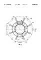
- FIG. 2is a partial top plan view of the froth flotation cell of FIG. 1, showing the central launder, secondary launder, plurality of radial launders and a wash assembly.
- FIG. 3ais an elevational view taken along the axis of a radial launder showing the connection between a radial launder and the central launder.
- FIG. 3bis a side elevational view, perpendicular to the axis of a radial launder, showing the connection between a radial launder and the central launder.
- FIG. 3cis a side elevational view, perpendicular to the axis of a radial launder, showing the connection of a radial launder to the secondary circumferential launder, the connection of the secondary circumferential launder to the standpipe of the flotation cell and a wash assembly positioned in the secondary circumferential launder.
- FIG. 1shows an embodiment of a froth flotation cell according to the present invention that includes a tank 10 and an impeller or rotor 12 rotatably disposed in the tank 10 for generating froth from a pulp phase or slurry in the tank 10.
- the impeller 12includes a plurality of vertical vanes or propeller blades 14 disposed in a generally cylindrical configuration about a rotation axis 16.
- the impeller 12is connected to a vertically oriented drive shaft 18, which is drivingly coupled at an upper end to a drive assembly 20 that includes a conventional motor, transmission belts, and bearings (none shown).
- the lower end of the impeller 12is surrounded by an upper end of a cylindrical draft tube extension or spacer element 21, which is coupled at its lower end to a conical draft tube 22.
- the draft tube 22is spaced from a lower wall or panel 24 of tank 10 by a plurality of support members 26.
- the support members 26define a plurality of openings 28 through which pulp or slurry 27 moves and is drawn into the draft tube 22.
- the upper end 12a of the impeller 12is surrounded by a perforated dispenser 30, coaxially aligned with the drive shaft 18, and acts to facilitate shearing of air bubbles and to eliminate vortexing of the pulp phase.
- a perforated dispenser 30Positioned over and about the disperser 30 is a perforated conical hood 32 for stabilizing the pulp phase.
- the impeller 12is positioned near the top of the fluid volume and the hood 32, which functions to reduce turbulence in the slurry 27.
- a crowder deviceis usually placed above the hood 32 and impeller 12.
- the structure and function of a crowder deviceis described in U.S. Pat. No. 5,661,917 to Degner, which is hereby incorporated by reference.
- the disclosures of U.S. Pat. No. 4,737,272 to Szatkowski et al. and U.S. Pat. No. 3,993,563 to Degnerare also incorporated by reference.
- the disperser 30is a standpipe 34 through which air is mixed into the pulp or slurry 27.
- the impeller 12creates a vortex within the standpipe 34 which allows for mixing and entrainment of air into the pulp or slurry 27.
- baffles 56Attached to the inside wall 11 of the tank 10 are a plurality of baffles 56.
- the baffles 56are plates which are preferably circumferentially or angularly equispaced and mounted substantially in a radial and vertical direction.
- the impeller 12 motioncauses the slurry 27 (or fluid mass) to move radially (or in an angular motion), which tends to reduce the effectiveness of the flotation cell 1.
- the use of bafflesis described in co-pending U.S. patent application Ser. No. 08/920,800, which is incorporated in writing.
- the purpose of the bafflesis to decrease the angular movement of the slurry mass 27 and to increase the radial movement of the slurry mass 27.
- the froth flotation cell 1also includes an outer launder 40 (also referred to herein as the "central” or “main launder”) at or adjacent to an outer periphery of the tank 10.
- the outer launder 40is fixed preferably near the upper end around the inside periphery of the tank 10.
- the outer launder 40may, however, be disposed at the outer side 10b of the tank 10.
- An overflow lip 44 of the outer launder 40defines or determines the froth level, which is generally located slightly above the vertical position of the overflow lip 44.
- one or more radial launderssuch as launders 36, are connected at their one end to the outer launder 40, and extend inward therefrom.
- the radial launders 36are preferably circumferentially or angularly equispaced.
- Each radial launder 36has an overflow lip 38 similar to the central launder's overflow lip 44.
- the central launder's overflow lip 44 and each radial launder's overflow lip 38are aligned in a coplanar fashion so that the definition or determination of the froth level initially set by the central overflow lip 44 is unchanged.
- a secondary launder (also referred to as the "inner" launder) 50may be disposed in the tank 10 and inside the outer launder 40. If a secondary launder 50 is utilized, then each radial launder 36 preferably has its second end connected to a secondary launder 50.
- the secondary launder 50is preferably concentric with and of smaller diameter than the outer launder 40.
- the secondary launder 50also has an overflow lip 54, which is coplanar with the radial launder overflow lips 38 and the outer launder overflow lip 44.
- the secondary launder 50may be structurally attached to the standpipe 34 by using a plurality of brackets 60 as shown in FIG. 3c.
- the radial launders 36are connected to the central launder 40 by flange-type brackets 62.
- a cutout 64 in the wall of outer launder 40is provided in order to create a continuous fluid path from the radial launder 36 to the outer launder 40.
- a gasket 66In between the radial launder 36 and the outer launder 40 is a gasket 66 which prevents fluid from leaking either in or out of the radial launders 36 and the outer launder 40.
- each radial launder 36is similarly connected to the secondary launder 50 by another flange-type bracket 70 and a gasket 72 to prevent leakage.
- the connection between each radial launder 36 and the secondary launder 50also includes a cutout (not shown) to allow for a continuous fluid path between each radial launder 36 and the inner launder 50.
- each radial launder 36is shaped so that it has a greater vertical depth at the connection with the outer launder 40 than it has at the connection with the secondary launder 50. This creates a slope in the bottom of the radial launder 36 that begins at the secondary launder 50 and continues downward until the connection at the outer launder 40.
- launders 36, 40, and 50create a network of launders which are in continuous fluid communication with each other. Froth which has been formed inside the tank 10 flows into the various launders via the overflow lips 38, 44, and 54. In this configuration, the froth may follow any of the various flow paths to reach the outer launder 40 and ultimately exit through a discharge pipe 46. For example, if the froth initially collects in the secondary launder 50, as shown by directional arrow 100 in FIG. 2, it will travel through the secondary launder 50 to one or more radial launders 36 as shown by directional arrows 102.
- This frothwill continue down the radial launder(s) 36 as shown by directional arrows 104 into the central launder 50.
- the frothflows through the central launder 50 as shown by directional arrows 106, until it exits the discharge pipe 46 as indicated by directional arrow 108.
- Frothcan also initially enter into one of the radial launders 36 or even the outer launder 40 and then follow a similar but shorter path depending on the initial point of overflow.
- the frothis carried from one launder to the next by gravity based on the slope of the radial launders 36.
- the configuration of the launders described aboveprovides a greater surface area for collecting froth throughout the tank 10, which allows faster collection of the froth and then the discharge from the tank 10 compared to launders which do not use radial and/or secondary launders. This enhances the effectiveness of the flotation cell 1. It has been determined that eight radial launders such as launders 36 and one secondary launder, such as launder 50, are sufficient for a majority of flotation cells. A lesser number of radial launders 36 may be utilized. Additionally, a flotation cell may be built without a secondary launder 50.
- a wash assembly 80may be provided.
- the wash assembly 80contains a plurality of spray nozzles 82 which, in the present embodiment, are placed so as to introduce a fluid (which is innocuous to, and compatible with, the mineral value recovery process) at various points in the secondary launder 50, see FIG. 3c.
- the introduction of a fluid at these locationsin essence, reduces the viscosity of the froth and allows the froth to travel more rapidly from the secondary launder 50 to the radial launders 36 and then to the central launder 50.
- the use of a wash assembly 80expedites the removal of froth collected in the secondary launder 50. This also allows the use of radial launders 36 with shallower slope.
- An additional wash assembly(not shown) may be placed so as to introduce sprayed liquid at a predetermined location in the radial launders 36 to further increase the flow rate of froth through the radial launders 36.
- An advantage of providing a network of launders such as described above,is that the froth is removed from the tank 10 efficiently regardless of the froth flow characteristics. For example, if froth is flowing with an angular momentum, then the froth is captured by the radial launders 36. Likewise, if the flow of the froth is either radially outward from the center of the tank, or radially inward towards the center of the tank, the froth is collected by either the outer launder 40 or the secondary launder 50 respectively.
- the present inventionalso is applicable to any type of froth flotation cell regardless of the mechanism (e.g. a pump) used to suspend mineral particulates and disperse air bubbles into the slurry.
- a froth flotation cell without a rotating impeller 12, draft tube 22, disperser 30, or hood 32can benefit from the system of launders made according to the present invention.
Landscapes
- Life Sciences & Earth Sciences (AREA)
- Engineering & Computer Science (AREA)
- Biotechnology (AREA)
- Chemical & Material Sciences (AREA)
- Dispersion Chemistry (AREA)
- Paper (AREA)
- Degasification And Air Bubble Elimination (AREA)
- Physical Water Treatments (AREA)
Abstract
Description
Claims (21)
Priority Applications (1)
| Application Number | Priority Date | Filing Date | Title |
|---|---|---|---|
| US09/170,400US6095336A (en) | 1997-08-29 | 1998-10-13 | Flotation cell with radial launders for enhancing froth removal |
Applications Claiming Priority (2)
| Application Number | Priority Date | Filing Date | Title |
|---|---|---|---|
| US92080097A | 1997-08-29 | 1997-08-29 | |
| US09/170,400US6095336A (en) | 1997-08-29 | 1998-10-13 | Flotation cell with radial launders for enhancing froth removal |
Related Parent Applications (1)
| Application Number | Title | Priority Date | Filing Date |
|---|---|---|---|
| US92080097AContinuation-In-Part | 1997-08-29 | 1997-08-29 |
Publications (1)
| Publication Number | Publication Date |
|---|---|
| US6095336Atrue US6095336A (en) | 2000-08-01 |
Family
ID=25444429
Family Applications (1)
| Application Number | Title | Priority Date | Filing Date |
|---|---|---|---|
| US09/170,400Expired - LifetimeUS6095336A (en) | 1997-08-29 | 1998-10-13 | Flotation cell with radial launders for enhancing froth removal |
Country Status (7)
| Country | Link |
|---|---|
| US (1) | US6095336A (en) |
| AR (2) | AR017034A1 (en) |
| AU (1) | AU748205B2 (en) |
| CA (1) | CA2246173C (en) |
| CL (1) | CL2010001036A1 (en) |
| PE (1) | PE51999A1 (en) |
| ZA (1) | ZA987866B (en) |
Cited By (17)
| Publication number | Priority date | Publication date | Assignee | Title |
|---|---|---|---|---|
| US20040099575A1 (en)* | 2002-11-27 | 2004-05-27 | Khan Latif A. | Method and apparatus for froth flotation |
| US20040188896A1 (en)* | 2003-01-08 | 2004-09-30 | Letelier Carlos Q. | Flotation device |
| US20060169644A1 (en)* | 2005-02-02 | 2006-08-03 | Petreco International, Inc. | Single-cell mechanical flotation system |
| CN100443192C (en)* | 2006-10-26 | 2008-12-17 | 北京矿冶研究总院 | Bubble pushing device for a flotation machine |
| DE102008014791A1 (en) | 2008-03-18 | 2009-09-24 | Siemens Aktiengesellschaft | Flotation cell for the recovery of valuable material particles |
| US20100167339A1 (en)* | 2007-06-19 | 2010-07-01 | Eastman Chemical Company | Process for microalgae conditioning and concentration |
| EP2500102A1 (en) | 2011-03-15 | 2012-09-19 | Siemens Aktiengesellschaft | Flotation apparatus with a fluid distribution element for creating a fluid flow towards the froth collecting device |
| WO2013067343A1 (en)* | 2011-11-04 | 2013-05-10 | Flsmidth A/S | Flotation cell vortex stabilizer |
| WO2017194294A1 (en) | 2016-05-09 | 2017-11-16 | Unilever N.V. | Device and method for purification of wastewater |
| CN107971143A (en)* | 2017-11-16 | 2018-05-01 | 武汉工程大学 | A kind of bilobed wheel mechanical agitation self-suction type flotation machine and method for floating |
| WO2019166687A1 (en)* | 2018-03-02 | 2019-09-06 | Outotec (Finland) Oy | Froth flotation cell |
| WO2019180682A1 (en) | 2018-03-23 | 2019-09-26 | Flsmidth A/S | Flotation machine apparatus and method of using the same |
| CN110681497A (en)* | 2019-09-29 | 2020-01-14 | 张子辉 | A flotation equipment for coal industry is convenient for collect |
| WO2021084430A1 (en) | 2019-10-28 | 2021-05-06 | Flsmidth A/S | Rotor for self-aspirated flotation cells |
| WO2022079604A1 (en) | 2020-10-12 | 2022-04-21 | Flsmidth A/S | Flotation cell vortex stabilizer |
| AU2019335749B2 (en)* | 2018-09-05 | 2022-09-01 | Bgrimm Machinery & Automation Technology Co., Ltd. | Inflation-type large flotation machine and flotation method therefor |
| CN116727116A (en)* | 2023-08-16 | 2023-09-12 | 山东瑞福锂业有限公司 | Ore flotation separation equipment |
Citations (21)
| Publication number | Priority date | Publication date | Assignee | Title |
|---|---|---|---|---|
| US1310051A (en)* | 1919-07-15 | Flotation obe-sepabatdira apparatus | ||
| US1374499A (en)* | 1915-12-27 | 1921-04-12 | William E Greenawalt | Flotation apparatus |
| US3342331A (en)* | 1965-05-24 | 1967-09-19 | Maxwell John Russell | Flotation machine |
| US3491880A (en)* | 1967-12-07 | 1970-01-27 | Arthur G Mckee Co | Flotation apparatus and process |
| US3701421A (en)* | 1970-04-29 | 1972-10-31 | Technequip Ltd | Method of mineral separation by froth floatation |
| US3701451A (en)* | 1970-09-03 | 1972-10-31 | Nelco Corp | Molded electrical junction box |
| US3802569A (en)* | 1971-09-14 | 1974-04-09 | Mitsui Mining & Smelting Co | Flotation machine |
| US3993563A (en)* | 1975-04-28 | 1976-11-23 | Envirotech Corporation | Gas ingestion and mixing device |
| US4247391A (en)* | 1979-03-09 | 1981-01-27 | Lloyd Philip J D | Froth flotation cell and method of operation |
| SU865405A1 (en)* | 1976-03-24 | 1981-09-23 | Всесоюзный Ордена Трудового Красного Знамени Научно-Исследовательский И Проектный Институт Механической Обработки Полезных Ископаемых "Механобр" | Pneumomechanical type flotation machine |
| US4311240A (en)* | 1978-09-13 | 1982-01-19 | Fried. Krupp Gessellschaft mit beschraankter Haftung | Flotation apparatus |
| US4737272A (en)* | 1986-04-11 | 1988-04-12 | Baker International Corporation | Froth flotation method and apparatus |
| US5039400A (en)* | 1987-10-07 | 1991-08-13 | Outokumpu Oy | Flotation machine |
| US5219467A (en)* | 1991-06-05 | 1993-06-15 | Outokumpu Research Oy | Method for concentrating ore slurries by means of intensive agitation conditioning and simultaneous flotation, and an apparatus for the same |
| US5234112A (en)* | 1991-10-02 | 1993-08-10 | Servicios Corporativos Frisco S.A. De C.V. | Flotation reactor with external bubble generator |
| US5251764A (en)* | 1991-03-27 | 1993-10-12 | Outomec Oy | Flotation machine |
| WO1993020945A1 (en)* | 1992-04-16 | 1993-10-28 | Atomaer Pty Ltd | Froth wash and froth removal system |
| US5431286A (en)* | 1994-01-06 | 1995-07-11 | Inco Limited | Recirculating column flotation apparatus |
| US5472094A (en)* | 1993-10-04 | 1995-12-05 | Electric Power Research Institute | Flotation machine and process for removing impurities from coals |
| US5542546A (en)* | 1994-05-07 | 1996-08-06 | Kali Und Salz Gmbh | Process and apparatus for non-agitated flotation of substances with a low degree of hydrophoby and/or low stability in the foam structure, in particular of salt mixtures |
| US5611917A (en)* | 1995-11-02 | 1997-03-18 | Baker Hughes Incorporated | Flotation cell crowder device |
- 1998
- 1998-08-28ZAZA987866Apatent/ZA987866B/enunknown
- 1998-08-28AUAU81954/98Apatent/AU748205B2/ennot_activeExpired
- 1998-08-28CACA002246173Apatent/CA2246173C/ennot_activeExpired - Lifetime
- 1998-08-31ARARP980104343Apatent/AR017034A1/enunknown
- 1998-08-31PEPE1998000809Apatent/PE51999A1/ennot_activeIP Right Cessation
- 1998-10-13USUS09/170,400patent/US6095336A/ennot_activeExpired - Lifetime
- 1999
- 1999-10-13ARARP990105184Apatent/AR020802A2/enunknown
- 2010
- 2010-09-29CLCL2010001036Apatent/CL2010001036A1/enunknown
Patent Citations (21)
| Publication number | Priority date | Publication date | Assignee | Title |
|---|---|---|---|---|
| US1310051A (en)* | 1919-07-15 | Flotation obe-sepabatdira apparatus | ||
| US1374499A (en)* | 1915-12-27 | 1921-04-12 | William E Greenawalt | Flotation apparatus |
| US3342331A (en)* | 1965-05-24 | 1967-09-19 | Maxwell John Russell | Flotation machine |
| US3491880A (en)* | 1967-12-07 | 1970-01-27 | Arthur G Mckee Co | Flotation apparatus and process |
| US3701421A (en)* | 1970-04-29 | 1972-10-31 | Technequip Ltd | Method of mineral separation by froth floatation |
| US3701451A (en)* | 1970-09-03 | 1972-10-31 | Nelco Corp | Molded electrical junction box |
| US3802569A (en)* | 1971-09-14 | 1974-04-09 | Mitsui Mining & Smelting Co | Flotation machine |
| US3993563A (en)* | 1975-04-28 | 1976-11-23 | Envirotech Corporation | Gas ingestion and mixing device |
| SU865405A1 (en)* | 1976-03-24 | 1981-09-23 | Всесоюзный Ордена Трудового Красного Знамени Научно-Исследовательский И Проектный Институт Механической Обработки Полезных Ископаемых "Механобр" | Pneumomechanical type flotation machine |
| US4311240A (en)* | 1978-09-13 | 1982-01-19 | Fried. Krupp Gessellschaft mit beschraankter Haftung | Flotation apparatus |
| US4247391A (en)* | 1979-03-09 | 1981-01-27 | Lloyd Philip J D | Froth flotation cell and method of operation |
| US4737272A (en)* | 1986-04-11 | 1988-04-12 | Baker International Corporation | Froth flotation method and apparatus |
| US5039400A (en)* | 1987-10-07 | 1991-08-13 | Outokumpu Oy | Flotation machine |
| US5251764A (en)* | 1991-03-27 | 1993-10-12 | Outomec Oy | Flotation machine |
| US5219467A (en)* | 1991-06-05 | 1993-06-15 | Outokumpu Research Oy | Method for concentrating ore slurries by means of intensive agitation conditioning and simultaneous flotation, and an apparatus for the same |
| US5234112A (en)* | 1991-10-02 | 1993-08-10 | Servicios Corporativos Frisco S.A. De C.V. | Flotation reactor with external bubble generator |
| WO1993020945A1 (en)* | 1992-04-16 | 1993-10-28 | Atomaer Pty Ltd | Froth wash and froth removal system |
| US5472094A (en)* | 1993-10-04 | 1995-12-05 | Electric Power Research Institute | Flotation machine and process for removing impurities from coals |
| US5431286A (en)* | 1994-01-06 | 1995-07-11 | Inco Limited | Recirculating column flotation apparatus |
| US5542546A (en)* | 1994-05-07 | 1996-08-06 | Kali Und Salz Gmbh | Process and apparatus for non-agitated flotation of substances with a low degree of hydrophoby and/or low stability in the foam structure, in particular of salt mixtures |
| US5611917A (en)* | 1995-11-02 | 1997-03-18 | Baker Hughes Incorporated | Flotation cell crowder device |
Cited By (37)
| Publication number | Priority date | Publication date | Assignee | Title |
|---|---|---|---|---|
| US20040099575A1 (en)* | 2002-11-27 | 2004-05-27 | Khan Latif A. | Method and apparatus for froth flotation |
| US6793079B2 (en) | 2002-11-27 | 2004-09-21 | University Of Illinois | Method and apparatus for froth flotation |
| US20040256294A1 (en)* | 2002-11-27 | 2004-12-23 | Khan Latif A. | Apparatus for froth cleaning |
| US20050051465A1 (en)* | 2002-11-27 | 2005-03-10 | Khan Latif A. | Method for froth flotation |
| US7328806B2 (en) | 2002-11-27 | 2008-02-12 | University Of Illinois | Apparatus for froth cleaning |
| US20040188896A1 (en)* | 2003-01-08 | 2004-09-30 | Letelier Carlos Q. | Flotation device |
| US7404924B2 (en)* | 2003-01-08 | 2008-07-29 | Ffe Minerals Corp. | Flotation device |
| US20060169644A1 (en)* | 2005-02-02 | 2006-08-03 | Petreco International, Inc. | Single-cell mechanical flotation system |
| US7438809B2 (en)* | 2005-02-02 | 2008-10-21 | Petreco International Inc. | Single-cell mechanical flotation system |
| WO2006083730A3 (en)* | 2005-02-02 | 2009-04-09 | Cameron Int Corp | Single-cell mechanical flotation system |
| CN100443192C (en)* | 2006-10-26 | 2008-12-17 | 北京矿冶研究总院 | Bubble pushing device for a flotation machine |
| US8512998B2 (en) | 2007-06-19 | 2013-08-20 | Renewable Algal Energy, Llc | Process for microalgae conditioning and concentration |
| US20100167339A1 (en)* | 2007-06-19 | 2010-07-01 | Eastman Chemical Company | Process for microalgae conditioning and concentration |
| EP2167431A4 (en)* | 2007-06-19 | 2012-11-07 | Renewable Algal Energy Llc | Process and apparatus for adsorptive bubble separation |
| US9358553B2 (en) | 2007-06-19 | 2016-06-07 | Renewable Algal Energy, Llc | Process for microalgae conditioning and concentration |
| EP3138818A1 (en)* | 2007-06-19 | 2017-03-08 | Renewable Algal Energy, LLC | Process and apparatus for adsorptive bubble separation |
| DE102008014791A1 (en) | 2008-03-18 | 2009-09-24 | Siemens Aktiengesellschaft | Flotation cell for the recovery of valuable material particles |
| WO2009115348A1 (en)* | 2008-03-18 | 2009-09-24 | Siemens Aktiengesellschaft | Flotation cell for obtaining valuable material particles |
| EP2500102A1 (en) | 2011-03-15 | 2012-09-19 | Siemens Aktiengesellschaft | Flotation apparatus with a fluid distribution element for creating a fluid flow towards the froth collecting device |
| WO2012123258A1 (en) | 2011-03-15 | 2012-09-20 | Siemens Aktiengesellschaft | Flotation device comprising a fluid distribution element for generating a flow that is directed at the foam collecting unit |
| WO2013067343A1 (en)* | 2011-11-04 | 2013-05-10 | Flsmidth A/S | Flotation cell vortex stabilizer |
| WO2017194294A1 (en) | 2016-05-09 | 2017-11-16 | Unilever N.V. | Device and method for purification of wastewater |
| CN107971143B (en)* | 2017-11-16 | 2019-10-22 | 武汉工程大学 | A double-impeller mechanical stirring self-priming flotation machine and flotation method |
| CN107971143A (en)* | 2017-11-16 | 2018-05-01 | 武汉工程大学 | A kind of bilobed wheel mechanical agitation self-suction type flotation machine and method for floating |
| EP3758850A4 (en)* | 2018-03-02 | 2021-10-27 | Outotec (Finland) Oy | FOAM FLOTATION CELL |
| US20200391225A1 (en)* | 2018-03-02 | 2020-12-17 | Outotec (Finland) Oy | Froth flotation cell |
| WO2019166687A1 (en)* | 2018-03-02 | 2019-09-06 | Outotec (Finland) Oy | Froth flotation cell |
| AU2018411260B2 (en)* | 2018-03-02 | 2022-07-28 | Metso Finland Oy | Froth flotation cell |
| US12330170B2 (en)* | 2018-03-02 | 2025-06-17 | Outotec (Finland) Oy | Froth flotation cell |
| WO2019180682A1 (en) | 2018-03-23 | 2019-09-26 | Flsmidth A/S | Flotation machine apparatus and method of using the same |
| AU2019335749B2 (en)* | 2018-09-05 | 2022-09-01 | Bgrimm Machinery & Automation Technology Co., Ltd. | Inflation-type large flotation machine and flotation method therefor |
| CN110681497A (en)* | 2019-09-29 | 2020-01-14 | 张子辉 | A flotation equipment for coal industry is convenient for collect |
| CN110681497B (en)* | 2019-09-29 | 2021-10-26 | 张子辉 | A flotation equipment for coal industry is convenient for collect |
| WO2021084430A1 (en) | 2019-10-28 | 2021-05-06 | Flsmidth A/S | Rotor for self-aspirated flotation cells |
| WO2022079604A1 (en) | 2020-10-12 | 2022-04-21 | Flsmidth A/S | Flotation cell vortex stabilizer |
| CN116727116A (en)* | 2023-08-16 | 2023-09-12 | 山东瑞福锂业有限公司 | Ore flotation separation equipment |
| CN116727116B (en)* | 2023-08-16 | 2023-10-24 | 山东瑞福锂业有限公司 | Ore flotation separation equipment |
Also Published As
| Publication number | Publication date |
|---|---|
| CL2010001036A1 (en) | 2011-02-11 |
| CA2246173A1 (en) | 1999-02-28 |
| AR020802A2 (en) | 2002-05-29 |
| PE51999A1 (en) | 1999-06-14 |
| AR017034A1 (en) | 2001-08-22 |
| ZA987866B (en) | 1999-03-01 |
| AU8195498A (en) | 1999-03-11 |
| CA2246173C (en) | 2009-07-14 |
| AU748205B2 (en) | 2002-05-30 |
Similar Documents
| Publication | Publication Date | Title |
|---|---|---|
| US6095336A (en) | Flotation cell with radial launders for enhancing froth removal | |
| US3972815A (en) | Mixing apparatus | |
| US5407584A (en) | Water clarification method | |
| US6811699B2 (en) | Method and apparatus for mixing fluids, separating fluids, and separating solids from fluids | |
| CN111570100B (en) | Jet atomization flotation equipment | |
| US4842478A (en) | Dental suction apparatus | |
| US5464536A (en) | Apparatus for centrifugally separating a fluid mixture into its component parts | |
| EP0171143B1 (en) | Pump | |
| CA1038090A (en) | Reactor for biological water treatment | |
| US4434061A (en) | Solids-liquid separation | |
| US4163723A (en) | Continuously operated liquid-solids separator | |
| WO2013067343A1 (en) | Flotation cell vortex stabilizer | |
| US6036871A (en) | Method and device for separating heavier from lighter parts of aqueous slurries by means of centrifugal force effects | |
| AU777248B2 (en) | Flotation cells with devices to enhance recovery of froth containing mineral values | |
| CN212740998U (en) | Coagulation sedimentation system with coagulation sedimentation tank and rotational flow air flotation | |
| CN111570097B (en) | Flotation complete equipment | |
| US4613431A (en) | Froth flotation separation apparatus | |
| EP0496765A1 (en) | Method and apparatus for separation by flotation in a centrifugal field | |
| US4815929A (en) | Eddy pump | |
| US4871448A (en) | Mechanical flotation machine | |
| US2969879A (en) | Liquid and gas mixing machine | |
| EP0069119A1 (en) | RECOVERY SYSTEM FOR LIQUIDS. | |
| US6090286A (en) | Separator centrifuge | |
| CN1122731A (en) | Bubble floatation machine with separated stirring part and separation part | |
| US6116582A (en) | Mixer for mixing two fluids in a container having a hollow rotor with a pervious portion and a liquid seal covering a non-pervious rotor portion |
Legal Events
| Date | Code | Title | Description |
|---|---|---|---|
| AS | Assignment | Owner name:BAKER HUGHES INCORPORATED, TEXAS Free format text:ASSIGNMENT OF ASSIGNORS INTEREST;ASSIGNORS:REDDEN, LORIN;HUNT, JERRY W.;FOOT, DONALD G., JR.;REEL/FRAME:009623/0244;SIGNING DATES FROM 19981118 TO 19981201 | |
| STCF | Information on status: patent grant | Free format text:PATENTED CASE | |
| AS | Assignment | Owner name:GL&V MANAGEMENT HUNGARY KFT., HUNGARY Free format text:ASSIGNMENT OF ASSIGNORS INTEREST;ASSIGNOR:BAKER HUGHES INCORPORATED;REEL/FRAME:014027/0715 Effective date:20021108 | |
| FEPP | Fee payment procedure | Free format text:PAYOR NUMBER ASSIGNED (ORIGINAL EVENT CODE: ASPN); ENTITY STATUS OF PATENT OWNER: LARGE ENTITY Free format text:PAYER NUMBER DE-ASSIGNED (ORIGINAL EVENT CODE: RMPN); ENTITY STATUS OF PATENT OWNER: LARGE ENTITY | |
| FPAY | Fee payment | Year of fee payment:4 | |
| FPAY | Fee payment | Year of fee payment:8 | |
| SULP | Surcharge for late payment | Year of fee payment:7 | |
| REMI | Maintenance fee reminder mailed | ||
| AS | Assignment | Owner name:VENTOMATIC A/S, DENMARK Free format text:ASSIGNMENT OF ASSIGNORS INTEREST;ASSIGNOR:GL&V MANAGEMENT HUNGARY KFT.;REEL/FRAME:020540/0590 Effective date:20070806 | |
| AS | Assignment | Owner name:FLSMIDTH TECHNOLOGY A/S, DENMARK Free format text:CHANGE OF NAME;ASSIGNOR:VENTOMATIC A/S;REEL/FRAME:020555/0239 Effective date:20071211 | |
| FEPP | Fee payment procedure | Free format text:PAYER NUMBER DE-ASSIGNED (ORIGINAL EVENT CODE: RMPN); ENTITY STATUS OF PATENT OWNER: LARGE ENTITY Free format text:PAYOR NUMBER ASSIGNED (ORIGINAL EVENT CODE: ASPN); ENTITY STATUS OF PATENT OWNER: LARGE ENTITY | |
| AS | Assignment | Owner name:FLSMIDTH A/S, DENMARK Free format text:MERGER;ASSIGNOR:FLSMIDTH TECHNOLOGY A/S;REEL/FRAME:022868/0067 Effective date:20080907 | |
| FPAY | Fee payment | Year of fee payment:12 |