US6094261A - Method and apparatus for distinguishing fiber-optic cables - Google Patents
Method and apparatus for distinguishing fiber-optic cablesDownload PDFInfo
- Publication number
- US6094261A US6094261AUS09/015,829US1582998AUS6094261AUS 6094261 AUS6094261 AUS 6094261AUS 1582998 AUS1582998 AUS 1582998AUS 6094261 AUS6094261 AUS 6094261A
- Authority
- US
- United States
- Prior art keywords
- light
- cable
- cables
- fiber
- light source
- Prior art date
- Legal status (The legal status is an assumption and is not a legal conclusion. Google has not performed a legal analysis and makes no representation as to the accuracy of the status listed.)
- Expired - Lifetime
Links
- 238000000034methodMethods0.000titleclaimsabstractdescription14
- 230000003287optical effectEffects0.000claimsdescription8
- 230000008878couplingEffects0.000claims2
- 238000010168coupling processMethods0.000claims2
- 238000005859coupling reactionMethods0.000claims2
- 238000001429visible spectrumMethods0.000claims2
- 230000013011matingEffects0.000claims1
- 238000009434installationMethods0.000abstractdescription6
- 239000003990capacitorSubstances0.000description6
- 238000012360testing methodMethods0.000description4
- 238000010586diagramMethods0.000description3
- 239000004065semiconductorSubstances0.000description3
- 230000004075alterationEffects0.000description2
- 238000001514detection methodMethods0.000description2
- 230000006872improvementEffects0.000description2
- 238000004519manufacturing processMethods0.000description2
- 230000007246mechanismEffects0.000description2
- 238000012986modificationMethods0.000description2
- 230000004048modificationEffects0.000description2
- 230000008569processEffects0.000description2
- RYGMFSIKBFXOCR-UHFFFAOYSA-NCopperChemical compound[Cu]RYGMFSIKBFXOCR-UHFFFAOYSA-N0.000description1
- 238000013019agitationMethods0.000description1
- XAGFODPZIPBFFR-UHFFFAOYSA-NaluminiumChemical compound[Al]XAGFODPZIPBFFR-UHFFFAOYSA-N0.000description1
- 229910052782aluminiumInorganic materials0.000description1
- 230000005540biological transmissionEffects0.000description1
- 238000005253claddingMethods0.000description1
- 239000003086colorantSubstances0.000description1
- 238000010276constructionMethods0.000description1
- 229910052802copperInorganic materials0.000description1
- 239000010949copperSubstances0.000description1
- 239000000835fiberSubstances0.000description1
- 239000011521glassSubstances0.000description1
- 230000005923long-lasting effectEffects0.000description1
- 239000013307optical fiberSubstances0.000description1
- 230000001960triggered effectEffects0.000description1
- 230000000007visual effectEffects0.000description1
Images


Classifications
- G—PHYSICS
- G02—OPTICS
- G02B—OPTICAL ELEMENTS, SYSTEMS OR APPARATUS
- G02B6/00—Light guides; Structural details of arrangements comprising light guides and other optical elements, e.g. couplings
- G02B6/24—Coupling light guides
- G02B6/42—Coupling light guides with opto-electronic elements
- G02B6/4292—Coupling light guides with opto-electronic elements the light guide being disconnectable from the opto-electronic element, e.g. mutually self aligning arrangements
- G—PHYSICS
- G02—OPTICS
- G02B—OPTICAL ELEMENTS, SYSTEMS OR APPARATUS
- G02B6/00—Light guides; Structural details of arrangements comprising light guides and other optical elements, e.g. couplings
- G02B6/24—Coupling light guides
- G02B6/42—Coupling light guides with opto-electronic elements
- G02B6/4201—Packages, e.g. shape, construction, internal or external details
- G02B6/4202—Packages, e.g. shape, construction, internal or external details for coupling an active element with fibres without intermediate optical elements, e.g. fibres with plane ends, fibres with shaped ends, bundles
- G—PHYSICS
- G02—OPTICS
- G02B—OPTICAL ELEMENTS, SYSTEMS OR APPARATUS
- G02B6/00—Light guides; Structural details of arrangements comprising light guides and other optical elements, e.g. couplings
- G02B6/46—Processes or apparatus adapted for installing or repairing optical fibres or optical cables
- G02B6/56—Processes for repairing optical cables
- G02B6/562—Processes for repairing optical cables locatable, e.g. using magnetic means
- G—PHYSICS
- G02—OPTICS
- G02B—OPTICAL ELEMENTS, SYSTEMS OR APPARATUS
- G02B6/00—Light guides; Structural details of arrangements comprising light guides and other optical elements, e.g. couplings
- G02B6/24—Coupling light guides
- G02B6/42—Coupling light guides with opto-electronic elements
- G02B6/4201—Packages, e.g. shape, construction, internal or external details
- G02B6/4204—Packages, e.g. shape, construction, internal or external details the coupling comprising intermediate optical elements, e.g. lenses, holograms
Definitions
- the inventionpertains to a method and apparatus for distinguishing one fiber-optic cable from another when multiple cable termination points are grouped together.
- fiber-optic cablesto transmit digital data in local area networks, such as in office buildings is becoming increasingly more common. Some of the reasons for this phenomenon are the superior band width and superior transmission qualities of fiber-optic cables as compared to electrical wires made of copper or aluminum.
- a plurality of cablesare run to the same location. For example, in an office building, one end of a fiber-optic cable commonly terminates in a wiring closet along with possibly hundreds of other similar fiber-optic cables.
- the cablesare run through the ceilings and walls of the building to various other termination points in the building, such as offices, cubicles, secretarial stations, or data stations elsewhere in the building. Even at these types of locations, there may be many fiber-optic cable ends for connection to office and data equipment.
- an installerutilizes an ordinary flashlight with a specially designed adaptor for connecting to fiber-optic cable termination connectors. Particularly, he couples the flashlight to one end of the fiber-optic cable and then looks for the light coming out of the other end of the cable.
- This method of distinguishing fiber-optic cables from each othercan be extremely difficult for several reasons.
- the incandescent, white, light generated by an ordinary flashlightis not particularly well focused or of particularly strong intensity.
- the magnitude of the lightis constant in time. Accordingly, it is sometimes very difficult to detect with the naked eye the light coming out of the opposite end of the cable because it is weak and of the same color as the ambient light in the room.
- the cladding for many types of fiber-optic cables as well as the ferrule of most fiber optic connectorsare white, i.e., the same color as the light, thus making it even more difficult to detect.
- MarzariU.S. Pat. No. 4,797,556 issued to Marzari et al. (hereinafter Marzari) discloses one such complex optical continuity testing apparatus comprising equipment for transmitting infrared test light pulses down a fiber-optic cable and separate receiving equipment for detecting the pulses at the opposite end.
- the light pulsesare infrared and, therefore, are not detectable by the naked eye, but only by specifically designed receiving end equipment which then generates a visual and/or audible signal indicative of the power of the received light.
- Jeunansdiscloses an optical fiber testing device using a pulsed laser diode. Again, this device is not designed for detection of the pulsed light by the human eye, but rather by specially designed detection equipment. In fact, the light transmitted down the cable under test is reflected back by "sensor" equipment positioned at the opposite end of the cable, and detected at the same end from which it was transmitted. Accordingly, this device assumes that the identity of the opposite ends of the cable is already known. Further, since it uses a laser diode to generate the transmitted light, it would be inadvisable to use the naked eye to detect the light output at the opposite end since it might be harmful.
- Nimuradiscloses a method for identifying a specific fiber-optic cable out of a number of similar optical cables. This patent pertains primarily to detecting fluctuations in the light transmissive qualities of the cable due to physical agitation of the cable at a point intermediate its two ends. Accordingly, this device is not designed nor practical for tracing cables at a construction site.
- the inventionis a method and apparatus for distinguishing various fiber-optic cables from each other during and after an installation. It includes a fiber-optic light source that creates a high-intensity, colored, pulsed, light beam.
- the light beamis also reasonably highly collated, but not to the extent of a laser light source. Since the light is colored, it is more easily visible when it exits the opposite end of the cable. Further, because it is high-intensity, and highly collated, it also is more easily detectable by the naked eye at the opposite end of the cable. Finally, the fact that the beam is pulsed makes it more easily detectable, since it is easier for the naked eye to detect the on/off pulses of a light source as opposed to a steady state on or off condition.
- FIG. 1is a perspective view of a tool in accordance with the present invention.
- FIG. 2is a cross-sectional view of a tool in accordance with the present invention.
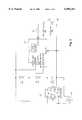
- FIG. 3is a block circuit diagram of a tool in accordance with the present invention.
- FIG. 4is a partially pictorial, partially schematic diagram of a fiber-optic cable installation in a building utilizing the present invention.
- the tool 10 in accordance with the present inventionis a hand-held, pocket-sized light source.
- the deviceincludes an enclosure 12 within which a battery 14 for providing power to drive the light source 22 may be contained.
- a manually operable switch 18Positioned on the front panel 16 is a manually operable switch 18 for turning the tool 10 on and off and selecting between two modes of operation, namely steady state and pulsed.
- the pulsed modethe light source 22 generates a pulsed light beam at a 50% duty cycle at a rate of about 3-5 hertz.
- the steady-state modethe light source 22 generates a steady beam.
- An adaptor mechanism 20 housing the light source 22appears on plate 16.
- the adaptor mechanism 20is designed to accept one or more of the standard type fiber-optic cable end couplers used in most installations, including ST, SC, FC, FDDI (FDS), and ESCON (RSD).
- the light source 22may be a high-intensity incandescent light bulb in a colored glass shade. However, preferably, the light source 22 is a high-intensity LED which generates a beam of a particular color which is easily distinguishable from ambient light. LEDs are commonly available on the market in colors such as green, red, blue, and orange. Such LEDs are particularly desirable because they are low power, generate highly intense, relatively highly collated beams and have relatively instant on/off characteristics such that they can be pulsed at a high rate without loss of intensity.
- the light generated by the light source 22exits the tool 10 through coupler 20 and into the cable (not shown).
- a lensmay be included in the coupler 20 to help direct the light into a narrowly focused beam directed into the cable.
- a second LED 19is an indicator LED that indicates whether the tool 10 is on, and, if so, the present mode of operation.
- the indicator LED 19preferably is coupled in series with the light source LED 22 such that, when the tool 10 is in the pulsed mode, the indicator LED 19 pulses in unison with the light source LED 22 and, when the tool is in the steady-state mode, the light source LED 22 and the indicator LED 19 are both steady on. Accordingly, the condition of the indicator LED discloses the mode of the unit. When the light source LED 22 is off, the indicator LED 19 is, of course, also off.
- the enclosure 12encloses a printed circuit board 21 upon which is mounted the LED 22, the indicator LED 19, a switch circuit 23 (including manual switch 18), and a pulser circuit 27.
- FIG. 3is a circuit diagram illustrating in greater detail the basic electrical components of the tool in accordance with the present invention, e.g., battery 14, LEDs 19 and 22, integrated circuit 23 and 27, and associated circuit elements.
- a power sourcesuch as battery 14 is provided.
- the batteryis a long-lasting 9 volt NiCad battery.
- the battery 14also may comprise one or more standard household batteries of any reasonable size such as AAA, AA, C, D.
- Switch circuit 23is a slide switch which may be a SS039-P023BA (2P3T) switch manufactured by T-MEC of Taiwan.
- Pulser circuit 27is a precision timer capable of generating a pulsed output signal.
- the ICM7555 manufactured by Harris Semiconductoris one such general purpose precision timer that may be used.
- switch circuit 23which is a three position switch.
- the right and left sides of the switchare mechanically coupled such that jumper 31 moves in unison with manually operated jumper 29.
- Each of the jumpersconnect two adjacent terminals of the switch circuit 23.
- the switchis shown in FIG. 3 in the middle position, in which terminals b and c on the left side of the switch are coupled by jumper 29 and terminals f and g on the right side are coupled together by jumper 31. In this position the tool is off. Particularly, as can be seen in FIG. 3, terminals a and d are coupled to the positive side of the battery 14, while neither of terminals b or c are coupled thereto. Thus, in the middle position, no power is provided to the circuit.
- the toolIn the upper position, i.e., with jumper 29 connecting terminals a and b and jumper 31 connecting terminals e and f, the tool will be in the steady-state mode. Particularly, power will be supplied from the battery to the V cc rail via terminals a and b in order to provide power to timer circuit 27. Further jumper 31 will be coupled across switch circuit terminals e and f, thus shorting out capacitor C1. As can be seen in the Figure, in this configuration, RESET is held high (no RESET) while the trigger and threshold terminals of pulser circuit 27 are tied to ground.
- the voltage into the discharge terminal of pulser circuit 27will be constant at a voltage level between V cc and ground dictated by the voltage divider formed by resistors R1 and R2.
- the values of resistors R1 and R2are selected to prevent discharge of the pulser.
- the Harris Semiconductor ICM7555 pulsergenerates a constant current at its output terminal, thus causing both light source LED 22 and indicator LED 19 to glow steadily.
- the Harris Semiconductor ICM7555 timer 27will be set up as an astable multivibrator thus causing the tool to operate in the pulsed mode. Particularly, power will be supplied from the battery via terminals c and d to the V cc rail to power the pulser circuit 27. Further jumper 31 will be coupled across switch circuit terminals g and h. Thus the threshold and trigger terminals of timer 27 will be coupled to ground through capacitor Cl. In this configuration, reset is still held high (no RESET) and the timer will operate as an astable multivibrator.
- capacitor C1As current pours into capacitor C1, the voltage presented to the trigger, threshold and discharge terminals will rise until the timer is triggered causing the output to turn off, thus turning off the LEDs 19 and 22.
- the capacitor C1When the output turns off, the capacitor C1 will discharge through the discharge terminal timer 27 until the voltage across capacitor C1 drops low enough to cause the threshold and trigger voltages to turn the output back on, thus causing the capacitor C1 to start charging again.
- This processruns continuously (an astable multivibrator) while the switch is in the lower position.
- the pulse generatormay be adjustable and the tool 10 may include a dial or other means for controlling the rate and/or duty cycle of the pulse generator, such is believed to be unnecessary.
- the light sourceis pulsed on and off at a 50% duty cycle at a rate of between 1 and 10 hertz and more preferably at a rate of between 3 and 6 hertz.
- FIG. 4illustrates the use of the present invention in the exemplary environment of an office building.
- a wiring closet 110is shown in an office building 100.
- a plurality of fiber-optic cables 112 1 -112 21terminate at one or more junction boxes or patch panels 104 in the closet 110. It would not be unusual for the number of fiber-optic cables terminating in a wiring closet in an office building to exceed 100 cables. Cables are routed through the walls and ceilings of the building 100 to various termination points such as individual offices 118, secretarial stations or cubicles 120 and other equipment closets 124. At many locations, particularly equipment closets and other wiring closets, many fiber-optic cables may terminate which originated either at wiring closet 110 or other locations.
- cablesmay share the same route for any span of their entire lengths. For instance, cables may 1) share the same route for their entire length (e.g., cables 112 7-11 or 2) may start at the same location, share the same route for a span and then split off (e.g., cables 112 8 and 112 9 , or 3) may share the same route only for an intermediate span (not shown). Accordingly, at termination points, a group of several fiber-optic cables may exit from the wall bundled together in a group. Since, in many cases, all of the cables are essentially identical in appearance, it is difficult to ascertain the origination points of the various cables.
- the installercan return to the origination end of a cable, unhook it from the junction box and couple it to the tool 10 of the present invention.
- the installercan then turn the tool 10 on in the pulsed mode so that it begins to emit into the cable, the colored, pulsed, high-intensity, light beam heretofore described.
- the installercan then return to the location or locations where he or she believes that cable may terminate and observe with the naked eye which of the many possible cables is emitting a pulsed, colored, light beam at the same frequency and color of the light source 22.
- the processcan be repeated for as many cables as necessary.
- the tool of the present inventionis extremely light-weight, inexpensive to manufacture and simple to use. It does not require any receiving end equipment other than the naked eye.
Landscapes
- Physics & Mathematics (AREA)
- General Physics & Mathematics (AREA)
- Optics & Photonics (AREA)
- Light Guides In General And Applications Therefor (AREA)
Abstract
Description
Claims (8)
Priority Applications (1)
| Application Number | Priority Date | Filing Date | Title |
|---|---|---|---|
| US09/015,829US6094261A (en) | 1998-01-29 | 1998-01-29 | Method and apparatus for distinguishing fiber-optic cables |
Applications Claiming Priority (1)
| Application Number | Priority Date | Filing Date | Title |
|---|---|---|---|
| US09/015,829US6094261A (en) | 1998-01-29 | 1998-01-29 | Method and apparatus for distinguishing fiber-optic cables |
Publications (1)
| Publication Number | Publication Date |
|---|---|
| US6094261Atrue US6094261A (en) | 2000-07-25 |
Family
ID=21773871
Family Applications (1)
| Application Number | Title | Priority Date | Filing Date |
|---|---|---|---|
| US09/015,829Expired - LifetimeUS6094261A (en) | 1998-01-29 | 1998-01-29 | Method and apparatus for distinguishing fiber-optic cables |
Country Status (1)
| Country | Link |
|---|---|
| US (1) | US6094261A (en) |
Cited By (31)
| Publication number | Priority date | Publication date | Assignee | Title |
|---|---|---|---|---|
| US20020069277A1 (en)* | 2000-11-22 | 2002-06-06 | Caveney Jack E. | Network revision system with local system ports |
| US20040213522A1 (en)* | 2003-04-28 | 2004-10-28 | Richard Hwang | Fiber optic cable identification kit and its method |
| US20060282529A1 (en)* | 2005-06-14 | 2006-12-14 | Panduit Corp. | Method and apparatus for monitoring physical network topology information |
| US20070032124A1 (en)* | 2005-08-08 | 2007-02-08 | Panduit Corp. | Systems and methods for detecting a patch cord end connection |
| US20070117444A1 (en)* | 2005-11-18 | 2007-05-24 | Panduit Corp. | Smart cable provisioning for a patch cord management system |
| US20070132503A1 (en)* | 2005-12-06 | 2007-06-14 | Panduit Corp. | Power patch panel with guided mac capability |
| US20070207666A1 (en)* | 2006-02-14 | 2007-09-06 | Panduit Corp. | Method and Apparatus for Patch Panel Patch Cord Documentation and Revision |
| US20070243725A1 (en)* | 2005-08-26 | 2007-10-18 | Panduit Corp. | Patch Field Documentation and Revision Systems |
| US20080043631A1 (en)* | 2005-05-19 | 2008-02-21 | Panduit Corp. | Method and Apparatus for Documenting Network Paths |
| US20080045075A1 (en)* | 2004-11-03 | 2008-02-21 | Panduit Corp. | Method and Apparatus for Patch Panel Patch Cord Documentation and Revision |
| US20080049627A1 (en)* | 2005-06-14 | 2008-02-28 | Panduit Corp. | Method and Apparatus for Monitoring Physical Network Topology Information |
| US7359634B1 (en)* | 2003-08-01 | 2008-04-15 | Cisco Technology, Inc. | Light color recognition for optical connection verification |
| US7373069B2 (en) | 2005-07-15 | 2008-05-13 | Daniel Otoniel Lazo | Fiber optic tester |
| US20080214140A1 (en)* | 2005-09-28 | 2008-09-04 | Panduit Corp. | Powered patch panel |
| US7455527B2 (en) | 2004-05-03 | 2008-11-25 | Panduit Corp. | Powered patch panel |
| US7519000B2 (en) | 2002-01-30 | 2009-04-14 | Panduit Corp. | Systems and methods for managing a network |
| WO2009019389A3 (en)* | 2007-07-23 | 2009-04-23 | France Telecom | Signal detection in optical fibre |
| US7656903B2 (en) | 2002-01-30 | 2010-02-02 | Panduit Corp. | System and methods for documenting networks with electronic modules |
| US20100157516A1 (en)* | 2008-12-22 | 2010-06-24 | Panduit Corp. | Physical infrastructure management system |
| US20100184323A1 (en)* | 2008-11-12 | 2010-07-22 | Panduit Corp. | Patch Cord with Insertion Detection and Light Illumination Capabilities |
| US20100210134A1 (en)* | 2009-02-19 | 2010-08-19 | Panduit Corp. | Cross connect patch guidance system |
| US20100238428A1 (en)* | 2007-06-07 | 2010-09-23 | Afl Telecommunications Llc | Method for detecting fiber optic fibers and ribbons |
| US20100267274A1 (en)* | 2007-10-19 | 2010-10-21 | Panduit Corp | Communication port identification system |
| US7938700B2 (en) | 2008-02-21 | 2011-05-10 | Panduit Corp. | Intelligent inter-connect and cross-connect patching system |
| US20110211456A1 (en)* | 2006-12-13 | 2011-09-01 | Panduit Corp. | High Performance Three-Port Switch For Managed Ethernet Systems |
| US20120086935A1 (en)* | 2010-10-07 | 2012-04-12 | At&T Intellectual Property I, L.P. | Identifiable visible light sources for fiber optic cables |
| US8208134B1 (en) | 2009-09-17 | 2012-06-26 | Erkan Gunal | Rapid visual fiber optic cable tester |
| US8325770B2 (en) | 2003-08-06 | 2012-12-04 | Panduit Corp. | Network managed device installation and provisioning technique |
| US20130021603A1 (en)* | 2011-07-18 | 2013-01-24 | Hobbes & Co., Ltd. | Optical signal inspection device |
| US8467041B2 (en) | 2010-12-01 | 2013-06-18 | Mark A. Dinjian | Fiber optic port signature applicator |
| US11047766B2 (en) | 2018-04-11 | 2021-06-29 | Afl Telecommunications Llc | Systems and methods for identification and testing of optical fibers |
Citations (20)
| Publication number | Priority date | Publication date | Assignee | Title |
|---|---|---|---|---|
| US3884585A (en)* | 1974-02-25 | 1975-05-20 | Us Navy | Fiber break detection methods for cables using multi-fiber optical bundles |
| US4288161A (en)* | 1979-06-04 | 1981-09-08 | Lockheed Corporation | Optical probe for detecting transitory and repetitive light signals |
| US4445086A (en)* | 1982-02-22 | 1984-04-24 | The Boeing Company | Multiconductor cable tester |
| US4671653A (en)* | 1985-09-23 | 1987-06-09 | Northern Telecom Limited | Test instrument for an optical fiber |
| US4671629A (en)* | 1984-04-26 | 1987-06-09 | Buehler Ltd. | Microscope for examining the surface finish of fiber optic ends |
| US4672198A (en)* | 1986-01-24 | 1987-06-09 | At&T Company And At&T Bell Laboratories | Signal sampler microbending fiber test clip |
| US4797556A (en)* | 1986-03-21 | 1989-01-10 | Amp Incorporated | Optical continuity testing apparatus with pulsating transmitter |
| US4800265A (en)* | 1986-03-21 | 1989-01-24 | Amp Incorporated | Optical fiber continuity testing with pulsating optical test signal |
| US4812743A (en)* | 1988-01-13 | 1989-03-14 | Northern Telecom Limited | Method and apparatus for detecting a narrowband signal |
| US4840482A (en)* | 1987-04-17 | 1989-06-20 | Sumitomo Electric Industries, Ltd. | Method of coated fiber identification in optical transmission network |
| US4870269A (en)* | 1987-02-02 | 1989-09-26 | Photonetics | Optical-fiber detection device which involves testing for good performance |
| US4940892A (en)* | 1989-04-05 | 1990-07-10 | Amp Incorporated | Optical discontinuity monitor system |
| US4981333A (en)* | 1989-09-27 | 1991-01-01 | Fotec, Inc. | Universal launch cable assembly and integrated idealized light source system using same |
| US5090018A (en)* | 1990-08-02 | 1992-02-18 | Siemens Aktiengesellschaft | Pulsed laser system for visually detecting faults in optical waveguides |
| US5196899A (en)* | 1991-07-19 | 1993-03-23 | Robert Serwatka | Fiber optic test light with multiple connector adapters |
| US5329348A (en)* | 1991-10-04 | 1994-07-12 | The Furukawa Electric Co., Ltd. | Method of identifying a particular optical cable out of a number of similar optical cables |
| US5463707A (en)* | 1993-08-25 | 1995-10-31 | Rohm Co., Ltd. | Optical fiber receptacle and method of producing the same |
| US5521701A (en)* | 1992-01-30 | 1996-05-28 | General Fiber Optics, Inc. | Optical power meter |
| US5570176A (en)* | 1995-02-13 | 1996-10-29 | Nortech Fibronic Inc. | Apparatus for converting a multimeter to an optical power meter |
| US5612780A (en)* | 1996-06-05 | 1997-03-18 | Harris Corporation | Device for detecting light emission from optical fiber |
- 1998
- 1998-01-29USUS09/015,829patent/US6094261A/ennot_activeExpired - Lifetime
Patent Citations (20)
| Publication number | Priority date | Publication date | Assignee | Title |
|---|---|---|---|---|
| US3884585A (en)* | 1974-02-25 | 1975-05-20 | Us Navy | Fiber break detection methods for cables using multi-fiber optical bundles |
| US4288161A (en)* | 1979-06-04 | 1981-09-08 | Lockheed Corporation | Optical probe for detecting transitory and repetitive light signals |
| US4445086A (en)* | 1982-02-22 | 1984-04-24 | The Boeing Company | Multiconductor cable tester |
| US4671629A (en)* | 1984-04-26 | 1987-06-09 | Buehler Ltd. | Microscope for examining the surface finish of fiber optic ends |
| US4671653A (en)* | 1985-09-23 | 1987-06-09 | Northern Telecom Limited | Test instrument for an optical fiber |
| US4672198A (en)* | 1986-01-24 | 1987-06-09 | At&T Company And At&T Bell Laboratories | Signal sampler microbending fiber test clip |
| US4797556A (en)* | 1986-03-21 | 1989-01-10 | Amp Incorporated | Optical continuity testing apparatus with pulsating transmitter |
| US4800265A (en)* | 1986-03-21 | 1989-01-24 | Amp Incorporated | Optical fiber continuity testing with pulsating optical test signal |
| US4870269A (en)* | 1987-02-02 | 1989-09-26 | Photonetics | Optical-fiber detection device which involves testing for good performance |
| US4840482A (en)* | 1987-04-17 | 1989-06-20 | Sumitomo Electric Industries, Ltd. | Method of coated fiber identification in optical transmission network |
| US4812743A (en)* | 1988-01-13 | 1989-03-14 | Northern Telecom Limited | Method and apparatus for detecting a narrowband signal |
| US4940892A (en)* | 1989-04-05 | 1990-07-10 | Amp Incorporated | Optical discontinuity monitor system |
| US4981333A (en)* | 1989-09-27 | 1991-01-01 | Fotec, Inc. | Universal launch cable assembly and integrated idealized light source system using same |
| US5090018A (en)* | 1990-08-02 | 1992-02-18 | Siemens Aktiengesellschaft | Pulsed laser system for visually detecting faults in optical waveguides |
| US5196899A (en)* | 1991-07-19 | 1993-03-23 | Robert Serwatka | Fiber optic test light with multiple connector adapters |
| US5329348A (en)* | 1991-10-04 | 1994-07-12 | The Furukawa Electric Co., Ltd. | Method of identifying a particular optical cable out of a number of similar optical cables |
| US5521701A (en)* | 1992-01-30 | 1996-05-28 | General Fiber Optics, Inc. | Optical power meter |
| US5463707A (en)* | 1993-08-25 | 1995-10-31 | Rohm Co., Ltd. | Optical fiber receptacle and method of producing the same |
| US5570176A (en)* | 1995-02-13 | 1996-10-29 | Nortech Fibronic Inc. | Apparatus for converting a multimeter to an optical power meter |
| US5612780A (en)* | 1996-06-05 | 1997-03-18 | Harris Corporation | Device for detecting light emission from optical fiber |
Cited By (65)
| Publication number | Priority date | Publication date | Assignee | Title |
|---|---|---|---|---|
| US7370106B2 (en)* | 2000-11-22 | 2008-05-06 | Panduit Corp. | Network revision system with local system ports |
| US20020069277A1 (en)* | 2000-11-22 | 2002-06-06 | Caveney Jack E. | Network revision system with local system ports |
| US7656903B2 (en) | 2002-01-30 | 2010-02-02 | Panduit Corp. | System and methods for documenting networks with electronic modules |
| US7519000B2 (en) | 2002-01-30 | 2009-04-14 | Panduit Corp. | Systems and methods for managing a network |
| US20040213522A1 (en)* | 2003-04-28 | 2004-10-28 | Richard Hwang | Fiber optic cable identification kit and its method |
| US6888996B2 (en)* | 2003-04-28 | 2005-05-03 | Richard Hwang | Fiber optic cable identification kit and its method |
| US7359634B1 (en)* | 2003-08-01 | 2008-04-15 | Cisco Technology, Inc. | Light color recognition for optical connection verification |
| US8325770B2 (en) | 2003-08-06 | 2012-12-04 | Panduit Corp. | Network managed device installation and provisioning technique |
| US7455527B2 (en) | 2004-05-03 | 2008-11-25 | Panduit Corp. | Powered patch panel |
| US20080045075A1 (en)* | 2004-11-03 | 2008-02-21 | Panduit Corp. | Method and Apparatus for Patch Panel Patch Cord Documentation and Revision |
| US7517243B2 (en) | 2004-11-03 | 2009-04-14 | Panduit Corp. | Method and apparatus for patch panel patch cord documentation and revision |
| US7756047B2 (en) | 2005-05-19 | 2010-07-13 | Panduit Corp. | Method and apparatus for documenting network paths |
| US7613124B2 (en) | 2005-05-19 | 2009-11-03 | Panduit Corp. | Method and apparatus for documenting network paths |
| US20080043631A1 (en)* | 2005-05-19 | 2008-02-21 | Panduit Corp. | Method and Apparatus for Documenting Network Paths |
| US20080049627A1 (en)* | 2005-06-14 | 2008-02-28 | Panduit Corp. | Method and Apparatus for Monitoring Physical Network Topology Information |
| US20060282529A1 (en)* | 2005-06-14 | 2006-12-14 | Panduit Corp. | Method and apparatus for monitoring physical network topology information |
| US7373069B2 (en) | 2005-07-15 | 2008-05-13 | Daniel Otoniel Lazo | Fiber optic tester |
| US7636050B2 (en) | 2005-08-08 | 2009-12-22 | Panduit Corp. | Systems and methods for detecting a patch cord end connection |
| US20110234416A1 (en)* | 2005-08-08 | 2011-09-29 | Panduit Corp. | Systems and Methods for Detecting a Patch Cord End Connection |
| US20070032124A1 (en)* | 2005-08-08 | 2007-02-08 | Panduit Corp. | Systems and methods for detecting a patch cord end connection |
| US8482421B2 (en) | 2005-08-08 | 2013-07-09 | Panduit Corp. | Systems and methods for detecting a patch cord end connection |
| US7969320B2 (en) | 2005-08-08 | 2011-06-28 | Panduit Corp. | Systems and methods for detecting a patch cord end connection |
| US7563102B2 (en) | 2005-08-26 | 2009-07-21 | Panduit Corp. | Patch field documentation and revision systems |
| US20070243725A1 (en)* | 2005-08-26 | 2007-10-18 | Panduit Corp. | Patch Field Documentation and Revision Systems |
| US9049499B2 (en) | 2005-08-26 | 2015-06-02 | Panduit Corp. | Patch field documentation and revision systems |
| US7978845B2 (en) | 2005-09-28 | 2011-07-12 | Panduit Corp. | Powered patch panel |
| US20080214140A1 (en)* | 2005-09-28 | 2008-09-04 | Panduit Corp. | Powered patch panel |
| US20070117444A1 (en)* | 2005-11-18 | 2007-05-24 | Panduit Corp. | Smart cable provisioning for a patch cord management system |
| US7811119B2 (en) | 2005-11-18 | 2010-10-12 | Panduit Corp. | Smart cable provisioning for a patch cord management system |
| US20070132503A1 (en)* | 2005-12-06 | 2007-06-14 | Panduit Corp. | Power patch panel with guided mac capability |
| US7768418B2 (en) | 2005-12-06 | 2010-08-03 | Panduit Corp. | Power patch panel with guided MAC capability |
| US7488206B2 (en) | 2006-02-14 | 2009-02-10 | Panduit Corp. | Method and apparatus for patch panel patch cord documentation and revision |
| US20070207666A1 (en)* | 2006-02-14 | 2007-09-06 | Panduit Corp. | Method and Apparatus for Patch Panel Patch Cord Documentation and Revision |
| US7534137B2 (en) | 2006-02-14 | 2009-05-19 | Panduit Corp. | Method and apparatus for patch panel patch cord documentation and revision |
| US20110211456A1 (en)* | 2006-12-13 | 2011-09-01 | Panduit Corp. | High Performance Three-Port Switch For Managed Ethernet Systems |
| US20100238428A1 (en)* | 2007-06-07 | 2010-09-23 | Afl Telecommunications Llc | Method for detecting fiber optic fibers and ribbons |
| WO2009019389A3 (en)* | 2007-07-23 | 2009-04-23 | France Telecom | Signal detection in optical fibre |
| US20100267274A1 (en)* | 2007-10-19 | 2010-10-21 | Panduit Corp | Communication port identification system |
| US8477031B2 (en) | 2007-10-19 | 2013-07-02 | Panduit Corp. | Communication port identification system |
| US7938700B2 (en) | 2008-02-21 | 2011-05-10 | Panduit Corp. | Intelligent inter-connect and cross-connect patching system |
| US9866458B2 (en) | 2008-02-21 | 2018-01-09 | Panduit Corp. | Intelligent inter-connect and cross-connect patching system |
| US8419465B2 (en) | 2008-02-21 | 2013-04-16 | Panduit Corp. | Intelligent inter-connect and cross-connect patching system |
| US8246397B2 (en) | 2008-02-21 | 2012-08-21 | Panduit Corp. | Intelligent inter-connect and cross-connect patching system |
| US8715001B2 (en) | 2008-02-21 | 2014-05-06 | Panduit Corp. | Intelligent inter-connect and cross-connect patching system |
| US8414319B2 (en) | 2008-11-12 | 2013-04-09 | Panduit Corp. | Patch cord with insertion detection and light illumination capabilities |
| US20100184323A1 (en)* | 2008-11-12 | 2010-07-22 | Panduit Corp. | Patch Cord with Insertion Detection and Light Illumination Capabilities |
| US8267706B2 (en) | 2008-11-12 | 2012-09-18 | Panduit Corp. | Patch cord with insertion detection and light illumination capabilities |
| US8708724B2 (en) | 2008-11-12 | 2014-04-29 | Panduit Corp. | Patch cord insertion detection and light illumination capabilities |
| US8306935B2 (en) | 2008-12-22 | 2012-11-06 | Panduit Corp. | Physical infrastructure management system |
| US9026486B2 (en) | 2008-12-22 | 2015-05-05 | Panduit Corp. | Physical infrastructure management system |
| US8719205B2 (en) | 2008-12-22 | 2014-05-06 | Panduit Corp. | Physical infrastructure management system |
| US10516580B2 (en) | 2008-12-22 | 2019-12-24 | Panduit Corp. | Physical infrastructure management system |
| US20100157516A1 (en)* | 2008-12-22 | 2010-06-24 | Panduit Corp. | Physical infrastructure management system |
| US8721360B2 (en) | 2009-02-19 | 2014-05-13 | Panduit Corp. | Methods for patch cord guidance |
| US8382511B2 (en) | 2009-02-19 | 2013-02-26 | Panduit Corp. | Cross connect patch guidance system |
| US8128428B2 (en) | 2009-02-19 | 2012-03-06 | Panduit Corp. | Cross connect patch guidance system |
| US20100210134A1 (en)* | 2009-02-19 | 2010-08-19 | Panduit Corp. | Cross connect patch guidance system |
| US8208134B1 (en) | 2009-09-17 | 2012-06-26 | Erkan Gunal | Rapid visual fiber optic cable tester |
| US8797518B2 (en)* | 2010-10-07 | 2014-08-05 | At&T Intellectual Property I, L.P. | Identifiable visible light sources for fiber optic cables |
| US20120086935A1 (en)* | 2010-10-07 | 2012-04-12 | At&T Intellectual Property I, L.P. | Identifiable visible light sources for fiber optic cables |
| US8467041B2 (en) | 2010-12-01 | 2013-06-18 | Mark A. Dinjian | Fiber optic port signature applicator |
| US8823925B2 (en) | 2010-12-01 | 2014-09-02 | Mark A. Dinjian | Fiber optic port signature applicator |
| US8520201B2 (en)* | 2011-07-18 | 2013-08-27 | Hobbes & Co., Ltd. | Optical signal inspection device |
| US20130021603A1 (en)* | 2011-07-18 | 2013-01-24 | Hobbes & Co., Ltd. | Optical signal inspection device |
| US11047766B2 (en) | 2018-04-11 | 2021-06-29 | Afl Telecommunications Llc | Systems and methods for identification and testing of optical fibers |
Similar Documents
| Publication | Publication Date | Title |
|---|---|---|
| US6094261A (en) | Method and apparatus for distinguishing fiber-optic cables | |
| US4839599A (en) | Multipiece cable testing device which functions as flashlight, continuity checker, and cable identifier | |
| CA2102978C (en) | Light curtain system with individual beam indicators and method of operation | |
| US3942859A (en) | Electrical conductor with light indicating means | |
| US7373069B2 (en) | Fiber optic tester | |
| KR101469597B1 (en) | Method and apparatus for propagating optical signals along with power feed to illuminators and electrical appliances | |
| EP0144897B1 (en) | Fiber optics system with self test capability | |
| US20100238428A1 (en) | Method for detecting fiber optic fibers and ribbons | |
| JPH10107739A (en) | Optical interconnect module | |
| CN107850737A (en) | For tracking the system and method for cable and cable for such system and method | |
| JPH09508980A (en) | Optical fiber connection monitor, patch panel control system and its use | |
| WO2016081298A1 (en) | Traceable optical fiber cable and filtered viewing device for enhanced traceability | |
| US10962443B1 (en) | Multi-fiber connector visual polarity and continuity tester | |
| US8823925B2 (en) | Fiber optic port signature applicator | |
| US4814693A (en) | Data cable test apparatus and method | |
| US20080061762A1 (en) | Remote Continuity and Cable Identifier and Polarity Checker System and Method | |
| US4632544A (en) | Optical cable testing | |
| US7218387B2 (en) | Method and apparatus for providing visual information indicative of tested fiber optic component | |
| US10254197B2 (en) | Optical fiber monitoring system | |
| CN202836924U (en) | Fiber hunting module and fiber hunting instrument | |
| CN1641386A (en) | Remote lamp status display via fiber optic system | |
| KR102004879B1 (en) | Optical fault position finding device type SFP | |
| KR200188728Y1 (en) | Optical cable test device | |
| CN109357844A (en) | A kind of quick hunting system of visible light | |
| US20090040064A1 (en) | Apparatus for Producing an Electric Signal Provided With Luminous Means Characterizing Said Signal |
Legal Events
| Date | Code | Title | Description |
|---|---|---|---|
| AS | Assignment | Owner name:L-COM, INC., MASSACHUSETTS Free format text:ASSIGNMENT OF ASSIGNORS INTEREST;ASSIGNOR:CONTARINO, JR., ALFRED F.;REEL/FRAME:009010/0348 Effective date:19980122 | |
| STCF | Information on status: patent grant | Free format text:PATENTED CASE | |
| FEPP | Fee payment procedure | Free format text:PAYOR NUMBER ASSIGNED (ORIGINAL EVENT CODE: ASPN); ENTITY STATUS OF PATENT OWNER: SMALL ENTITY | |
| FPAY | Fee payment | Year of fee payment:4 | |
| AS | Assignment | Owner name:FREEPORT FINANCIAL LLC, ILLINOIS Free format text:SECURITY INTEREST;ASSIGNOR:L-COM, INC.;REEL/FRAME:017564/0553 Effective date:20060424 | |
| FPAY | Fee payment | Year of fee payment:8 | |
| FPAY | Fee payment | Year of fee payment:12 | |
| AS | Assignment | Owner name:L-COM, INC., MASSACHUSETTS Free format text:RELEASE OF SECURITY INTEREST IN INTELLECTUAL PROPERTY COLLATERAL;ASSIGNOR:FREEPORT FINANCIAL LLC, AS AGENT;REEL/FRAME:028680/0698 Effective date:20120725 | |
| AS | Assignment | Owner name:GENERAL ELECTRIC CAPITAL CORPORATION, AS COLLATERA Free format text:PATENT SECURITY AGREEMENT;ASSIGNOR:L-COM, INC.;REEL/FRAME:029047/0947 Effective date:20120924 | |
| AS | Assignment | Owner name:ANTARES CAPITAL LP, AS AGENT, ILLINOIS Free format text:ASSIGNMENT OF INTELLECTUAL PROPERTY SECURITY AGREEMENT;ASSIGNOR:GENERAL ELECTRIC CAPITAL CORPORATION, AS COLLATERAL AGENT;REEL/FRAME:036433/0539 Effective date:20150821 | |
| AS | Assignment | Owner name:ANTARES CAPITAL LP, AS ADMINISTRATIVE AGENT, ILLIN Free format text:SECURITY INTEREST;ASSIGNOR:L-COM, INC.;REEL/FRAME:039271/0549 Effective date:20160727 Owner name:MILESTEK CORPORATION, TEXAS Free format text:TERMINATION AND RELEASE OF GRANT OF SECURITY INTEREST IN INTELLECTUAL PROPERTY RIGHTS;ASSIGNOR:ANTARES CAPITAL LP, AS AGENT (AS SUCCESSOR IN INTEREST TO GENERAL ELECTRIC CAPITAL CORPORATION, AS AGENT);REEL/FRAME:039492/0592 Effective date:20160727 Owner name:L-COM, INC., MASSACHUSETTS Free format text:TERMINATION AND RELEASE OF GRANT OF SECURITY INTEREST IN INTELLECTUAL PROPERTY RIGHTS;ASSIGNOR:ANTARES CAPITAL LP, AS AGENT (AS SUCCESSOR IN INTEREST TO GENERAL ELECTRIC CAPITAL CORPORATION, AS AGENT);REEL/FRAME:039492/0592 Effective date:20160727 | |
| AS | Assignment | Owner name:ANTARES CAPITAL LP, AS ADMINISTRATIVE AGENT, ILLIN Free format text:SECURITY INTEREST;ASSIGNOR:L-COM, INC.;REEL/FRAME:039280/0614 Effective date:20160727 | |
| AS | Assignment | Owner name:INFINITE ELECTRONICS INTERNATIONAL, INC., CALIFORNIA Free format text:PATENT RELEASE 2L;ASSIGNOR:ANTARES CAPITAL LP, AS ADMINISTRATIVE AGENT;REEL/FRAME:055489/0136 Effective date:20210302 Owner name:INFINITE ELECTRONICS INTERNATIONAL, INC., CALIFORNIA Free format text:PATENT RELEASE;ASSIGNOR:ANTARES CAPITAL LP, AS ADMINISTRATIVE AGENT;REEL/FRAME:055490/0130 Effective date:20210302 |