US6092815A - Active chassis in a motor vehicle - Google Patents
Active chassis in a motor vehicleDownload PDFInfo
- Publication number
- US6092815A US6092815AUS09/203,152US20315298AUS6092815AUS 6092815 AUS6092815 AUS 6092815AUS 20315298 AUS20315298 AUS 20315298AUS 6092815 AUS6092815 AUS 6092815A
- Authority
- US
- United States
- Prior art keywords
- roll moment
- sub
- suspension system
- recited
- axle
- Prior art date
- Legal status (The legal status is an assumption and is not a legal conclusion. Google has not performed a legal analysis and makes no representation as to the accuracy of the status listed.)
- Expired - Fee Related
Links
- 239000000725suspensionSubstances0.000claimsabstractdescription49
- 238000000034methodMethods0.000abstractdescription8
- 230000001276controlling effectEffects0.000description10
- 238000005259measurementMethods0.000description4
- 238000010586diagramMethods0.000description3
- 238000006073displacement reactionMethods0.000description3
- 238000013016dampingMethods0.000description2
- 230000001133accelerationEffects0.000description1
- 230000033001locomotionEffects0.000description1
- 230000001105regulatory effectEffects0.000description1
Images


Classifications
- B—PERFORMING OPERATIONS; TRANSPORTING
- B60—VEHICLES IN GENERAL
- B60G—VEHICLE SUSPENSION ARRANGEMENTS
- B60G17/00—Resilient suspensions having means for adjusting the spring or vibration-damper characteristics, for regulating the distance between a supporting surface and a sprung part of vehicle or for locking suspension during use to meet varying vehicular or surface conditions, e.g. due to speed or load
- B60G17/02—Spring characteristics, e.g. mechanical springs and mechanical adjusting means
- B60G17/027—Mechanical springs regulated by fluid means
- B60G17/0272—Mechanical springs regulated by fluid means the mechanical spring being a coil spring
- B—PERFORMING OPERATIONS; TRANSPORTING
- B60—VEHICLES IN GENERAL
- B60G—VEHICLE SUSPENSION ARRANGEMENTS
- B60G17/00—Resilient suspensions having means for adjusting the spring or vibration-damper characteristics, for regulating the distance between a supporting surface and a sprung part of vehicle or for locking suspension during use to meet varying vehicular or surface conditions, e.g. due to speed or load
- B60G17/015—Resilient suspensions having means for adjusting the spring or vibration-damper characteristics, for regulating the distance between a supporting surface and a sprung part of vehicle or for locking suspension during use to meet varying vehicular or surface conditions, e.g. due to speed or load the regulating means comprising electric or electronic elements
- B60G17/018—Resilient suspensions having means for adjusting the spring or vibration-damper characteristics, for regulating the distance between a supporting surface and a sprung part of vehicle or for locking suspension during use to meet varying vehicular or surface conditions, e.g. due to speed or load the regulating means comprising electric or electronic elements characterised by the use of a specific signal treatment or control method
- B—PERFORMING OPERATIONS; TRANSPORTING
- B60—VEHICLES IN GENERAL
- B60G—VEHICLE SUSPENSION ARRANGEMENTS
- B60G2800/00—Indexing codes relating to the type of movement or to the condition of the vehicle and to the end result to be achieved by the control action
- B60G2800/01—Attitude or posture control
- B60G2800/012—Rolling condition
- B60G2800/0122—Roll rigidity ratio; Warping
- B—PERFORMING OPERATIONS; TRANSPORTING
- B60—VEHICLES IN GENERAL
- B60G—VEHICLE SUSPENSION ARRANGEMENTS
- B60G2800/00—Indexing codes relating to the type of movement or to the condition of the vehicle and to the end result to be achieved by the control action
- B60G2800/90—System Controller type
- B60G2800/91—Suspension Control
- B60G2800/915—Suspension load distribution
Definitions
- the present inventionrelates to an active chassis in a motor vehicle and to a method of controlling a chassis.
- German Patent Application No. 44 14 022 A1describes a chassis equipped with an active suspension system between the wheels and the body of the vehicle.
- the suspension systemhas a passive spring element assigned to each wheel and an active, controllable supporting unit on which the spring element is supported and whose stroke position can be adjusted with the help of a hydraulic displacement unit.
- the stroke positions of the supporting unitsare detected by displacement sensors, and the actual supporting forces acting between the wheels and the body of the vehicle are determined from the stroke positions in an electronic controller according to a linear relationship.
- the supporting forcesare compared in the electronic controller with predetermined setpoint supporting forces calculated from setpoint stroke positions.
- the control deviationthen results in a control signal to adjust the supporting units.
- German Patent Application No. 44 14 022 A1does not describe other possible uses.
- German Patent Application No. 41 17 897 A1describes a control concept for damping the stroke, pitch and roll motions of a chassis. This concept, which also permits adjustment of the roll torque distribution between the front and rear axles as an additional degree of freedom of the "chassis" system, is based on a variant of skyhook damping, as a result of which a controlling force, which depends on the rate of buildup, is determined.
- vertical buildup ratesmust first be determined at selected locations on the chassis. The vertical buildup rates are then used to calculate the rates of stroke, roll and pitch, which are then converted to quasi-modal rates from which setpoint forces for actively adjustable hydraulic cylinders are determined.
- German Patent Application No. 41 17 897 A1is capable of influencing a majority of degrees of freedom of the system.
- several control matrices with a plurality of coefficientsare needed for the control concept due to its complexity. Further, any determination of optimal coefficient values will be of great expense.
- Another disadvantageis that any buildup rates must be measured by sensors and the measurement of the buildup rates are more complicated that measurement of simple changes in position.
- An object of the present inventionis to provide an easily implemented method of controlling the roll moment distribution between the front and rear axles of a vehicle.
- the present inventionprovides an active chassis in a motor vehicle, with a controllable suspension system (1) comprising passive spring elements (3) between a wheel (5) of the vehicle and the vehicle body (6), as well as supporting units (4) which are provided for the spring elements (3) and can be adjusted by a control signal.
- Transducers (7)are provided for the supporting units (4) to detect state variables of the supporting units (4), as is a control unit (8) to generate the control signal from a setpoint signal (T soll ), which is predefined via an input element (9), and an actual signal (T soll , MW V ) determined from the state variables thus detected.
- the present inventionis characterized in that the roll moment distribution (T soll ) to be set between front and rear axles of the vehicle can be preselected as the setpoint signal in the input element (9), and an actual signal (T ist , MW V ) representing the actual roll moment distribution can be determined in the control unit (8) as a function of the state variables of the supporting units (4).
- the present inventionalso provides a method of controlling an active chassis in a motor vehicle, with a controllable suspension system (1) comprising passive spring elements (3) between a wheel (5) of the vehicle and the vehicle body (6) as well as controllable supporting units (4) provided for the spring elements (3).
- the state variables of the supporting units (4)is detected, manipulated and compared with setpoints (T soll , MW Vsoll ) to form a control signal.
- the methodis characterized in that the roll moment distribution (T soll ) to be set between a front axle and a rear axle of a vehicle is preselected, and the actual roll moment distribution (T ist ) is regulated to conform to the setpoint roll moment distribution (T soll ).
- the entire roll moment acting on the vehicle when turning a cornermay be distributed between the front and rear axles according to a predetermined percentage distribution.
- the roll moment distributionis specifically set in the form of a restraint as an additional degree of freedom of the system with statically redundant vehicles with four wheels used in order to provide a positive influence on driving performance.
- the actual roll moment distributioncan be attributed exclusively to the state variables characterizing the suspension system.
- these state variablesmay be position variables of the suspension strut, in particular the stroke of the supporting unit or the total stroke of the spring element and the supporting unit.
- the supporting force in the suspension strutcan be determined from the stroke, and the roll moments acting on each axle can be determined from the supporting force.
- the pressure in the supporting unitsis determined first as a state variable and used to determine the actuator force in the supporting units. This can be used to form the basis for calculating the roll moment.
- the control unithas various control elements where the measurement signals are processed further, converted as needed and compared with the setpoint signals generated in the input element.
- a control signalis generated from the control unit and is preferably sent to a final controlling element for adjusting the supporting units.
- the roll momentsare determined according to a predefined rule in a first processing element using the state variables obtained.
- the actual roll moment distributionis calculated from the roll moments acting on the respective axles in a second processing element downstream, including an adder and a divider.
- the control deviation from a predefined roll moment distributionis formed in a downstream subtractor, then in a third processing element, the control deviation is converted into a control deviation for the desired setpoint roll moment at the front axle by processing it with the total roll moment, and finally it is multiplied by a gain factor to obtain a suitably dimensioned control signal.
- the preselected roll moment distributionis first multiplied by the total roll moment in a setpoint manipulator, with the resulting generated signal representing the setpoint roll moment to be defined for the front axle.
- the actual roll moment occurring at the front axleis subtracted from this in a downstream subtractor.
- the difference, as the control deviation,is multiplied by a gain factor.
- FIG. 1shows a suspension strut having a passive spring element and an active supporting unit of the present invention
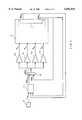
- FIG. 2shows a block diagram of an embodiment of the present invention for controlling a roll moment distribution
- FIG. 3shows a block diagram of another embodiment of the present invention for controlling a roll moment distribution.
- FIG. 1illustrates a suspension system 1 which is part of an active chassis.
- the suspension system 1has a total of four suspension struts 2, each arranged between a wheel 5 of a vehicle and a vehicle body 6.
- Each suspension strut 2has a passive spring element 3 and an active supporting unit 4.
- the active supporting unit 4can be connected in series with the passive spring element 3.
- the active supporting unit 4can be designed as a plunger.
- Spring element 3has spring constant c. Supporting force F in the suspension strut 2 is calculated accordingly with the equation:
- x Pdenotes a stroke of the supporting unit 4 or a plunger and x f denotes a spring stroke.
- FIG. 2illustrates a control concept provided to obtain a desired distribution of any roll moments on front and rear axles, e.g., MW H and MW V respectively, as the moments rotate about a longitudinal axis of a vehicle.
- a vehicle with active controlis represented as a controlled system in block 10.
- Stroke x P of the supporting unit 4 and stroke x f of the springs 3are sensed by sensors 7, preferably designed as position pickups.
- the sensed stroke x P of the supporting unit 4 and stroke x f of the springs 3are then sent to a first processing element 11 where supporting force F in a suspension strut 2 is calculated according to the above equation.
- sensors 7measure only a stroke x P of a supporting unit 4. If a vehicle is on a flat road surface, this embodiment of the present invention yields control results of equivalent quality to those obtained by measuring the stroke x P of the supporting unit 4 and the stroke x f of the springs 3.
- roll moment MW v for the front axleis:
- Roll moments MW V and MW H in signal formare sent to a second processing element 12 which is downstream from first processing element 11 and represents a combination of an adder and a divider.
- Processing element 12produces actual roll moment distribution T ist as its output signal by first adding incoming roll moments MW V and MW H in the adder and then in the divider dividing roll moment MW V acting on the front axle by the sum of the two roll moments according to the following equation:
- T istcan assume values between 0 and 1.
- the value 0can indicate that the entire roll moment acting on the vehicle is applied to the rear axle.
- the value 1can indicate that the entire roll moment is acting on the front axle.
- Third processing element 14supplies as its output signal the difference ⁇ MW V of the desired and actual roll moments on the front axle by multiplying control deviation ⁇ T by the sum of roll moments MW V , MW H according to the following equation:
- the number of amplifiers 17a-17dcorresponds to the number of suspension struts 2.
- the signs in front of gain factors K Tare selected so that control signals R vl for the left front and R hr for the right rear are positive, while control signals R vr for the right front and R hl for the left rear are negative.
- Control signals Rhave a physical dimension of a control voltage and are each sent to a final controlling element of a suspension strut 2 to control oil streams flowing into the supporting units 4 by controlling servo-valves.
- FIG. 3illustrates another embodiment of the present invention.
- state variablesare measured via transducers 7 and then used to determine roll moments MW V and MW H on the front and rear axles in first processing element 11.
- the roll moments MW V and MW Hare sent to a setpoint manipulator 15 which is designed as an adder and multiplier.
- the total of the roll momentsis multiplied by roll moment distribution T soll preset in input element 9, thus yielding as the output value a setpoint MW Vsoll for the roll moment to be preset for the front axle according to the following equation:
- control equationcan be obtained by combining the individual terms:
Landscapes
- Engineering & Computer Science (AREA)
- Mechanical Engineering (AREA)
- Vehicle Body Suspensions (AREA)
Abstract
Description
F=c*(x.sub.P -x.sub.f)
MW.sub.V =(F.sub.vl -F.sub.vr)*tread.sub.front
T.sub.ist =MW.sub.V /(MW.sub.V +MW.sub.H).
ΔT=T.sub.soll -T.sub.ist,
ΔMW.sub.V =ΔT*(MW.sub.V +MW.sub.H).
R=±K.sub.T *ΔMW.sub.V.
MW.sub.Vsoll =T.sub.soll *(MW.sub.V +MW.sub.H).
R=±K.sub.T *[MW.sub.V *(1-T.sub.soll)-MW.sub.H *T.sub.soll ].
Claims (15)
R.sub.vl =R.sub.hr =+K.sub.T *[MW.sub.V *(1-T.sub.soll)-MW.sub.H *T.sub.soll ]
R.sub.vr =R.sub.hl =-K.sub.T *[MW.sub.V *(1-T.sub.soll)-MW.sub.H *T.sub.soll ]
Applications Claiming Priority (2)
| Application Number | Priority Date | Filing Date | Title |
|---|---|---|---|
| DE19753205 | 1997-12-01 | ||
| DE19753205ADE19753205C2 (en) | 1997-12-01 | 1997-12-01 | Adjustable suspension system in an active chassis of a motor vehicle |
Publications (1)
| Publication Number | Publication Date |
|---|---|
| US6092815Atrue US6092815A (en) | 2000-07-25 |
Family
ID=7850366
Family Applications (1)
| Application Number | Title | Priority Date | Filing Date |
|---|---|---|---|
| US09/203,152Expired - Fee RelatedUS6092815A (en) | 1997-12-01 | 1998-12-01 | Active chassis in a motor vehicle |
Country Status (3)
| Country | Link |
|---|---|
| US (1) | US6092815A (en) |
| EP (1) | EP0919408B1 (en) |
| DE (2) | DE19753205C2 (en) |
Cited By (8)
| Publication number | Priority date | Publication date | Assignee | Title |
|---|---|---|---|---|
| US6352142B1 (en)* | 1999-03-22 | 2002-03-05 | Hyundai Motor Company | Active suspension system |
| US20050228565A1 (en)* | 2004-04-08 | 2005-10-13 | Herbert Lohner | Coordination of a vehicle dynamics control system with other vehicles stability systems |
| US20060212199A1 (en)* | 2005-03-16 | 2006-09-21 | Toyota Jidosha Kabushiki Kaisha | Suspension system |
| US20070040340A1 (en)* | 2004-02-03 | 2007-02-22 | Dirk Kesselgruber | Actuator, in particular for a chassis |
| US20150028551A1 (en)* | 2013-07-25 | 2015-01-29 | Tenneco Automotive Operating Company Inc. | Recuperating Passive And Active Suspension |
| US10434835B2 (en) | 2016-02-24 | 2019-10-08 | Tenneco Automotive Operating Company Inc. | Monotube active suspension system having different system layouts for controlling pump flow distribution |
| US20220266817A1 (en)* | 2019-05-09 | 2022-08-25 | Zf Friedrichshafen Ag | Method, control device and system for stabilizing a vehicle |
| US20240246539A1 (en)* | 2023-01-25 | 2024-07-25 | Dr. Ing. H.C. F. Porsche Aktiengesellschaft | Method for operating an active roll support system of a motor vehicle |
Families Citing this family (1)
| Publication number | Priority date | Publication date | Assignee | Title |
|---|---|---|---|---|
| DE102019002659A1 (en) | 2019-04-11 | 2019-10-17 | Daimler Ag | Device for roll stabilization of a vehicle |
Citations (11)
| Publication number | Priority date | Publication date | Assignee | Title |
|---|---|---|---|---|
| US4801155A (en)* | 1986-06-12 | 1989-01-31 | Nissan Motor Company, Limited | Actively controlled automotive suspension system with adjustable rolling-stability |
| DE3818188A1 (en)* | 1988-05-28 | 1989-12-07 | Daimler Benz Ag | ACTIVE SUSPENSION SYSTEM |
| DE3821609A1 (en)* | 1988-06-27 | 1989-12-28 | Bayerische Motoren Werke Ag | CONTROL DEVICE FOR STABILIZING A VEHICLE |
| US4961595A (en)* | 1988-10-18 | 1990-10-09 | Nissan Motor Company, Limited | Active suspension system for an automotive vehicle with slip angle dependent control for enhanced steering characteristics |
| US5104143A (en)* | 1989-09-27 | 1992-04-14 | Toyota Jidosha Kabushiki Kaisha | Vehicle suspension system with roll control variable according to vehicle speed |
| GB2252277A (en)* | 1990-11-30 | 1992-08-05 | Atsugi Unisia Corp | Suspension control system |
| DE4117897A1 (en)* | 1991-05-31 | 1992-12-03 | Bosch Gmbh Robert | SYSTEM FOR GENERATING SIGNALS FOR CONTROLLING OR CONTROLLING A CHASSIS CONTROLLABLE OR ADJUSTABLE IN ITS MOTION PROCESSES |
| US5228719A (en)* | 1991-04-10 | 1993-07-20 | Nissan Motor Co., Ltd. | Automotive active suspension system for anti-rolling control |
| US5253174A (en)* | 1990-12-27 | 1993-10-12 | Toyota Jidosha Kabushiki Kaisha | Active suspension with variable roll rigidity distribution ratio |
| DE4323544A1 (en)* | 1992-07-14 | 1994-01-20 | Mazda Motor | Vehicle suspension system with variable suspension characteristics - controls supply and discharge of fluid in to or out of hydraulic cylinders provided respectively between motor vehicle body and each wheel |
| DE4414022A1 (en)* | 1994-04-22 | 1995-10-26 | Daimler Benz Ag | Active suspension system |
- 1997
- 1997-12-01DEDE19753205Apatent/DE19753205C2/ennot_activeExpired - Fee Related
- 1998
- 1998-11-04DEDE59804037Tpatent/DE59804037D1/ennot_activeExpired - Fee Related
- 1998-11-04EPEP98120916Apatent/EP0919408B1/ennot_activeExpired - Lifetime
- 1998-12-01USUS09/203,152patent/US6092815A/ennot_activeExpired - Fee Related
Patent Citations (12)
| Publication number | Priority date | Publication date | Assignee | Title |
|---|---|---|---|---|
| US4801155A (en)* | 1986-06-12 | 1989-01-31 | Nissan Motor Company, Limited | Actively controlled automotive suspension system with adjustable rolling-stability |
| DE3818188A1 (en)* | 1988-05-28 | 1989-12-07 | Daimler Benz Ag | ACTIVE SUSPENSION SYSTEM |
| DE3821609A1 (en)* | 1988-06-27 | 1989-12-28 | Bayerische Motoren Werke Ag | CONTROL DEVICE FOR STABILIZING A VEHICLE |
| US4961595A (en)* | 1988-10-18 | 1990-10-09 | Nissan Motor Company, Limited | Active suspension system for an automotive vehicle with slip angle dependent control for enhanced steering characteristics |
| US5104143A (en)* | 1989-09-27 | 1992-04-14 | Toyota Jidosha Kabushiki Kaisha | Vehicle suspension system with roll control variable according to vehicle speed |
| GB2252277A (en)* | 1990-11-30 | 1992-08-05 | Atsugi Unisia Corp | Suspension control system |
| US5253174A (en)* | 1990-12-27 | 1993-10-12 | Toyota Jidosha Kabushiki Kaisha | Active suspension with variable roll rigidity distribution ratio |
| US5228719A (en)* | 1991-04-10 | 1993-07-20 | Nissan Motor Co., Ltd. | Automotive active suspension system for anti-rolling control |
| DE4117897A1 (en)* | 1991-05-31 | 1992-12-03 | Bosch Gmbh Robert | SYSTEM FOR GENERATING SIGNALS FOR CONTROLLING OR CONTROLLING A CHASSIS CONTROLLABLE OR ADJUSTABLE IN ITS MOTION PROCESSES |
| US5488562A (en)* | 1991-05-31 | 1996-01-30 | Robert Bosch Gmbh | System for generating signals for control or regulation of a chassis controllable or regulable in its sequences of movement |
| DE4323544A1 (en)* | 1992-07-14 | 1994-01-20 | Mazda Motor | Vehicle suspension system with variable suspension characteristics - controls supply and discharge of fluid in to or out of hydraulic cylinders provided respectively between motor vehicle body and each wheel |
| DE4414022A1 (en)* | 1994-04-22 | 1995-10-26 | Daimler Benz Ag | Active suspension system |
Cited By (15)
| Publication number | Priority date | Publication date | Assignee | Title |
|---|---|---|---|---|
| US6352142B1 (en)* | 1999-03-22 | 2002-03-05 | Hyundai Motor Company | Active suspension system |
| US20070040340A1 (en)* | 2004-02-03 | 2007-02-22 | Dirk Kesselgruber | Actuator, in particular for a chassis |
| US20050228565A1 (en)* | 2004-04-08 | 2005-10-13 | Herbert Lohner | Coordination of a vehicle dynamics control system with other vehicles stability systems |
| US7305292B2 (en)* | 2004-04-08 | 2007-12-04 | Robert Bosch Gmbh | Coordination of a vehicle dynamics control system with other vehicles stability systems |
| CN100462249C (en)* | 2005-03-16 | 2009-02-18 | 丰田自动车株式会社 | Suspension System |
| EP1705038A1 (en) | 2005-03-16 | 2006-09-27 | Toyota Jidosha Kabushiki Kaisha | Suspension system with roll stiffness distribution control device |
| US20060212199A1 (en)* | 2005-03-16 | 2006-09-21 | Toyota Jidosha Kabushiki Kaisha | Suspension system |
| US7725226B2 (en) | 2005-03-16 | 2010-05-25 | Toyota Jidosha Kabushiki Kaisha | Vehicle suspension system with roll stiffness distribution control |
| US20150028551A1 (en)* | 2013-07-25 | 2015-01-29 | Tenneco Automotive Operating Company Inc. | Recuperating Passive And Active Suspension |
| US9108484B2 (en)* | 2013-07-25 | 2015-08-18 | Tenneco Automotive Operating Company Inc. | Recuperating passive and active suspension |
| US9586456B2 (en) | 2013-07-25 | 2017-03-07 | Tenneco Automotive Operating Company Inc. | Recuperating passive and active suspension |
| US10434835B2 (en) | 2016-02-24 | 2019-10-08 | Tenneco Automotive Operating Company Inc. | Monotube active suspension system having different system layouts for controlling pump flow distribution |
| US20220266817A1 (en)* | 2019-05-09 | 2022-08-25 | Zf Friedrichshafen Ag | Method, control device and system for stabilizing a vehicle |
| US12246702B2 (en)* | 2019-05-09 | 2025-03-11 | Zf Friedrichshafen Ag | Method, control device and system for stabilizing a vehicle |
| US20240246539A1 (en)* | 2023-01-25 | 2024-07-25 | Dr. Ing. H.C. F. Porsche Aktiengesellschaft | Method for operating an active roll support system of a motor vehicle |
Also Published As
| Publication number | Publication date |
|---|---|
| EP0919408B1 (en) | 2002-05-08 |
| DE19753205A1 (en) | 1999-06-10 |
| DE19753205C2 (en) | 2000-07-13 |
| DE59804037D1 (en) | 2002-06-13 |
| EP0919408A1 (en) | 1999-06-02 |
Similar Documents
| Publication | Publication Date | Title |
|---|---|---|
| DE60010421T2 (en) | Rollover detection of a motor vehicle | |
| US6549842B1 (en) | Method and apparatus for determining an individual wheel surface coefficient of adhesion | |
| US5001636A (en) | Yaw motion control device | |
| US6529803B2 (en) | Roll over stability control for an automotive vehicle having rear wheel steering | |
| US6496758B2 (en) | Rollover stability control for an automotive vehicle using front wheel actuators | |
| EP0249246B1 (en) | Actively controlled automotive suspension system with adjustable rolling stability | |
| US7421954B2 (en) | Active suspension controller | |
| US5189615A (en) | Semi-active suspension control | |
| US7308351B2 (en) | Method for coordinating a vehicle dynamics control system with an active normal force adjustment system | |
| US5488562A (en) | System for generating signals for control or regulation of a chassis controllable or regulable in its sequences of movement | |
| US5586032A (en) | System for controlling a vehicle undercarriage based on road safety, travel comfort and standard modes of operation | |
| US6863356B2 (en) | Device and method for operating a motor vehicle | |
| CN108891410B (en) | Vehicle attitude control device | |
| EP0983919A2 (en) | A method for detecting a bank angle experienced by a moving vehicle | |
| US20030163231A1 (en) | Roll over stability control for an automotive vehicle | |
| US5556176A (en) | Method for controlling vehicle brake pressure as a function of the deviation of the actual slip of wheels relative to a desired slip | |
| JPH04505737A (en) | Vehicle steering system | |
| GB2382336A (en) | Vehicle yaw stability control | |
| JPS60154946A (en) | Regulator for graking force | |
| US6092815A (en) | Active chassis in a motor vehicle | |
| EP1659008B1 (en) | Method for the regulation or control of the damping force of an adjustable vehicle damper | |
| US5563789A (en) | System to generate signals for control or regulation of a controllable or regulable chassis | |
| US5646848A (en) | Method for proportionally controlling the brakes of a vehicle based on tire deformation | |
| JP2895198B2 (en) | Rear wheel steering angle control method | |
| JPH06331464A (en) | System to determine adhesion coefficient of vehicle |
Legal Events
| Date | Code | Title | Description |
|---|---|---|---|
| AS | Assignment | Owner name:DAIMLER-CHRYSLER AKTIENGESELLSCHAFT, GERMANY Free format text:ASSIGNMENT OF ASSIGNORS INTEREST;ASSIGNORS:RUTZ, RUDIGER;WINKLER, MARTIN;REEL/FRAME:009834/0256;SIGNING DATES FROM 19990202 TO 19990212 | |
| FEPP | Fee payment procedure | Free format text:PAYOR NUMBER ASSIGNED (ORIGINAL EVENT CODE: ASPN); ENTITY STATUS OF PATENT OWNER: LARGE ENTITY | |
| FPAY | Fee payment | Year of fee payment:4 | |
| FPAY | Fee payment | Year of fee payment:8 | |
| AS | Assignment | Owner name:DAIMLER AG, GERMANY Free format text:CHANGE OF NAME;ASSIGNOR:DAIMLER CHRYSLER AG;REEL/FRAME:021029/0447 Effective date:20071019 | |
| AS | Assignment | Owner name:RAMSLE TECHNOLOGY GROUP GMBH, LLC, DELAWARE Free format text:ASSIGNMENT OF ASSIGNORS INTEREST;ASSIGNOR:DAIMLER AG;REEL/FRAME:021719/0080 Effective date:20080727 | |
| FEPP | Fee payment procedure | Free format text:PAYOR NUMBER ASSIGNED (ORIGINAL EVENT CODE: ASPN); ENTITY STATUS OF PATENT OWNER: LARGE ENTITY Free format text:PAYER NUMBER DE-ASSIGNED (ORIGINAL EVENT CODE: RMPN); ENTITY STATUS OF PATENT OWNER: LARGE ENTITY | |
| FEPP | Fee payment procedure | Free format text:PAYOR NUMBER ASSIGNED (ORIGINAL EVENT CODE: ASPN); ENTITY STATUS OF PATENT OWNER: LARGE ENTITY Free format text:PAYER NUMBER DE-ASSIGNED (ORIGINAL EVENT CODE: RMPN); ENTITY STATUS OF PATENT OWNER: LARGE ENTITY | |
| REMI | Maintenance fee reminder mailed | ||
| LAPS | Lapse for failure to pay maintenance fees | ||
| STCH | Information on status: patent discontinuation | Free format text:PATENT EXPIRED DUE TO NONPAYMENT OF MAINTENANCE FEES UNDER 37 CFR 1.362 | |
| FP | Lapsed due to failure to pay maintenance fee | Effective date:20120725 | |
| AS | Assignment | Owner name:HANGER SOLUTIONS, LLC, GEORGIA Free format text:ASSIGNMENT OF ASSIGNORS INTEREST;ASSIGNOR:INTELLECTUAL VENTURES ASSETS 158 LLC;REEL/FRAME:051486/0425 Effective date:20191206 | |
| AS | Assignment | Owner name:INTELLECTUAL VENTURES ASSETS 158 LLC, DELAWARE Free format text:ASSIGNMENT OF ASSIGNORS INTEREST;ASSIGNOR:OL SECURITY LIMITED LIABILITY COMPANY;REEL/FRAME:051846/0192 Effective date:20191126 | |
| AS | Assignment | Owner name:21ST CENTURY GARAGE LLC, GEORGIA Free format text:ASSIGNMENT OF ASSIGNORS INTEREST;ASSIGNOR:HANGER SOLUTIONS, LLC;REEL/FRAME:052606/0910 Effective date:20200221 |