US6092774A - Keyboard positioning system - Google Patents
Keyboard positioning systemDownload PDFInfo
- Publication number
- US6092774A US6092774AUS09/198,086US19808698AUS6092774AUS 6092774 AUS6092774 AUS 6092774AUS 19808698 AUS19808698 AUS 19808698AUS 6092774 AUS6092774 AUS 6092774A
- Authority
- US
- United States
- Prior art keywords
- tray
- pair
- base
- rail
- members
- Prior art date
- Legal status (The legal status is an assumption and is not a legal conclusion. Google has not performed a legal analysis and makes no representation as to the accuracy of the status listed.)
- Expired - Lifetime
Links
- 238000005096rolling processMethods0.000claimsabstractdescription8
- 230000000284resting effectEffects0.000claimsdescription2
- 230000003014reinforcing effectEffects0.000claims2
- 230000007246mechanismEffects0.000abstractdescription18
- 238000005553drillingMethods0.000abstractdescription3
- 230000006378damageEffects0.000abstractdescription2
- 230000008878couplingEffects0.000abstract1
- 238000010168coupling processMethods0.000abstract1
- 238000005859coupling reactionMethods0.000abstract1
- 238000000034methodMethods0.000description4
- 239000000463materialSubstances0.000description3
- 238000006073displacement reactionMethods0.000description2
- 238000009434installationMethods0.000description2
- 239000002184metalSubstances0.000description2
- 229910052751metalInorganic materials0.000description2
- 150000002739metalsChemical class0.000description2
- 229920003023plasticPolymers0.000description2
- 239000004033plasticSubstances0.000description2
- 210000000707wristAnatomy0.000description2
- 239000002131composite materialSubstances0.000description1
- 230000001066destructive effectEffects0.000description1
- 239000006260foamSubstances0.000description1
- 239000011521glassSubstances0.000description1
- 238000003780insertionMethods0.000description1
- 230000037431insertionEffects0.000description1
- 238000012986modificationMethods0.000description1
- 230000004048modificationEffects0.000description1
- 238000000465mouldingMethods0.000description1
- 238000006748scratchingMethods0.000description1
- 230000002393scratching effectEffects0.000description1
Images


Classifications
- A—HUMAN NECESSITIES
- A47—FURNITURE; DOMESTIC ARTICLES OR APPLIANCES; COFFEE MILLS; SPICE MILLS; SUCTION CLEANERS IN GENERAL
- A47B—TABLES; DESKS; OFFICE FURNITURE; CABINETS; DRAWERS; GENERAL DETAILS OF FURNITURE
- A47B21/00—Tables or desks for office equipment, e.g. typewriters, keyboards
- A47B21/03—Tables or desks for office equipment, e.g. typewriters, keyboards with substantially horizontally extensible or adjustable parts other than drawers, e.g. leaves
- A47B21/0314—Platforms for supporting office equipment
- Y—GENERAL TAGGING OF NEW TECHNOLOGICAL DEVELOPMENTS; GENERAL TAGGING OF CROSS-SECTIONAL TECHNOLOGIES SPANNING OVER SEVERAL SECTIONS OF THE IPC; TECHNICAL SUBJECTS COVERED BY FORMER USPC CROSS-REFERENCE ART COLLECTIONS [XRACs] AND DIGESTS
- Y10—TECHNICAL SUBJECTS COVERED BY FORMER USPC
- Y10S—TECHNICAL SUBJECTS COVERED BY FORMER USPC CROSS-REFERENCE ART COLLECTIONS [XRACs] AND DIGESTS
- Y10S248/00—Supports
- Y10S248/917—Video display screen support
- Y10S248/918—Ancillary device support associated with a video display screen
Definitions
- Keyboard positioning apparatusare commonly used to support keyboards associated with computer terminals and the like.
- the positioning apparatusis typically mounted to a desk and includes a keyboard support tray which can be pulled out from underneath the desk.
- Conventional positioning apparatusemploy fasteners for attachment beneath the desk.
- fastenerssuch as screws
- the use of fastenersrequires holes to be drilled, and limits the apparatus to certain support surfaces that can receive the fasteners. It generally precludes the use of glass desk tops, for example.
- the attachment procedurecan be complicated and time-consuming, and requires the use of tools. It is also inconvenient to change the location of attachment for the apparatus, because the fasteners are not readily removable.
- clampscan be used in place of fasteners, they protrude under the desk with a substantial length and can block the movement of the keyboard on the support tray when it is slid under the desk.
- the present inventionis directed to a keyboard positioning system which avoids the problems and disadvantages of the prior art. This goal is accomplished by providing keyboard positioning apparatus that do not require complex mounting mechanisms or drilling holes in the desk.
- a specific embodimentemploys an apparatus that is supported on top of the desk.
- Another specific embodimentemploys a tool-less, adjustable, out-board clamping mechanism for releasably mounting the apparatus to the desk without requiring holes to be drilled in the base.
- the apparatus of the present inventioncan be easily adapted to a variety of support bases such as desks. The apparatus are easy to assemble and can be moved easily without destruction to the desks or similar support bases.
- an apparatus for supporting a keyboard relative to a basecomprises a tray guide supported on the base, the tray guide having a pair of spaced guide members.
- a tray railhas a pair of rail members each slidably engaging one of the pair of spaced guide members to slide between a front and a rear of the rail members.
- Each rail memberhas at least two rollers for providing rolling motion of the rail members on the base.
- a trayis coupled to the tray rail for supporting a keyboard.
- the tray guideis supported for providing sliding of the tray rail to at least partially overhang an edge of the base.
- an apparatus for supporting a keyboard relative to a basecomprises a keyboard tray having a plurality of rollers for providing rolling contact with the base and a pair of spaced rails disposed near two sides of the tray and extending at least substantially parallel to one another.
- a mechanismis positioned on the base for providing sliding movement of the pair of rails relative to the base to support the keyboard tray between a position with the rollers resting on the base and another position with the keyboard tray overhanging at least partially over an edge of the base.
- an apparatus for supporting a keyboard relative to a basecomprises a pair of spaced brackets.
- a pair of clampsreleasably couple the pair of spaced brackets nondestructively underneath the base.
- a pair of spaced slide membersare each coupled to one of the spaced brackets.
- a trayhas two sides each slidably coupled to one of the spaced slide members for supporting a keyboard to move in and out beneath the base.
- an apparatus for supporting a keyboard relative to a basecomprises a keyboard tray having two sides each housing a plurality of rolling members and a pair of spaced brackets.
- a pair of clampsreleasably couple the pair of spaced brackets nondestructively underneath the base adjacent and external to the two sides of the keyboard tray.
- a mechanismis coupled to the spaced brackets for providing sliding support of the plurality of rolling members housed in the two sides of the keyboard tray.
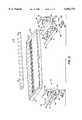
- FIG. 1is an exploded perspective view of a keyboard positioning system in accordance with an embodiment of the present invention
- FIG. 2is a partially exploded perspective view of a keyboard positioning system in accordance with another embodiment of the present invention.
- FIG. 3is a cross-sectional view of a sliding mechanism of the keyboard positioning system of FIG. 2;
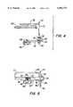
- FIG. 4is a close-up exploded perspective view of a clamp of the keyboard positioning system of FIG. 2;
- FIG. 5is a schematic elevational view of a clamped portion of the assembled keyboard positioning system of FIG. 2.
- FIG. 1shows a keyboard positioning system 10 which includes a keyboard tray 12 for supporting a keyboard (not shown).
- the tray 12typically is substantially rectangular, and preferably is large enough to hold a mouse as well as a keyboard, and includes openings in the rear portion for accommodating cables for the keyboard and mouse (not shown).
- the tray 12includes an optional keyboard pad 14 that may be made of a variety of materials such as foam or a gel for supporting the user's wrists, and may have different shapes.
- the pad 14is disposed in the front portion of the tray 12 and typically extends substantially across the length of the tray 12.
- the tray 12has a plurality of rollers 16 at the bottom to provide rolling support of the tray 12 relative to the surface of a base such as a desktop or the like (not shown).
- a basesuch as a desktop or the like
- the tray 12has four rollers 16 spaced near its four corners.
- the tray 12further includes a pair of spaced tray rail members 18 that are at least substantially parallel to one another and extend from the front to the back of the tray 12.
- the rail members 18are typically straight and substantially planar.
- the rail members 18are typically mounted near or at the bottom of the tray 12 along the right and left sides thereof.
- railmount screws 19are used to mount the rail members 18.
- the tray 12has two pairs of rollers 16 and each pair of rollers 16 are attached near the front and back ends of each tray rail member 18.
- a pair of tray guide members 20are supported on the base to provide guiding support for the rail members 18.
- the tray guide members 20serve as tracks on which the rail members 18 slide freely back and forth to allow the tray 12 to roll in and out on the base.
- the guide members 20have the substantially vertical configuration with upper constraints 22 to provide sliding support for the rail members 18.
- the rails members 18include protrusions or stops (not shown) near the front and back ends to limit the range of sliding movement of the rail members 18 relative to the guide members 20 to prevent disengagement between them.
- the guide bottom 24 of each guide member 20is supported on the base to have a substantially fixed position for constraining the movement of the tray 12.
- the embodiment shown in FIG. 1advantageously fixes the position of the guide members 20 relative to the base without requiring any permanent mounting of the guide bottoms 24 to the base or drilling holes in the base, as discussed below.
- the keyboard positioning system 10includes a platform 30 which is used, for example, for supporting a monitor or display, a computer terminal, and/or the like.
- the platform 30typically has a planar, substantially rectangular shape, and is supported on the base by a plurality of legs 32.
- the legs 32are desirably adjustable in height, for instance, by using stackable leg portions 34.
- each leg 32has two substantially circular cylindrical leg portions 34 that are stacked together.
- a leg washer 36 and a leg nut 38that cooperate with a leg screw 40 for attaching the leg 32 to the platform 30.
- Each leg 32further includes a leg pad 42 connected at the bottom which prevents scratching the surface of the base.
- the tray guide members 20are conveniently coupled to the pair of legs 32 at the front portion of the platform 30.
- the guide bottoms 24 of the guide members 20are shaped for easy attachment near the bottom of the legs 32, for instance, between the leg portions 34 and the leg pads 42.
- the weight of the platform 30 as well as the weight of any equipment (such as computer terminal and monitor) placed over the platform 30is used to fix the positions of the tray guide members 20 to provide stable support for the tray rail members 18 and the tray 12 without the need for complicated or destructive mounting to the base.
- the components of the keyboard positioning system 10are typically made of plastic or the like that can be made by molding or similar methods.
- the system 10will be typically light in weight. If additional structural or flexural strength is needed for the platform 30, particularly along its length, for supporting heavy equipment thereon, one or more support members or beams 44 are attached underneath the platform 30 to extend substantially across the length of the platform 30.
- the support members 44may also be oriented differently, such as diagonally across the platform 30.
- the platform 30 and the tray guide members 20will be at least substantially fixed in position on the base.
- the tray 12slides freely relative to the tray guide members 20 via the tray rail members 18 in and out below the platform 30, which is sufficiently tall to allow the tray 12 and keyboard (not shown) to slide thereunder. Because of the stable support provided by the tray guide members 20, the tray 12 at least partially overhangs an edge of the base when it is pulled out from under the platform 30 without toppling the platform 30 or otherwise creating any instability of the system 10.
- the tray guide member 20form a cantilever support for the tray rail members 18 and tray 12 in the overhang position under the weight of the platform 30 and any equipment disposed thereon.
- a keyboard positioning system 50employs a tool-less mounting mechanism for releasably supporting a keyboard tray 52 underneath a base (not shown) without requiring holes to be drilled in the base.
- the keyboard tray 52also has an optional pad 53 for supporting the user's wrists.
- the system 50includes a pair of spaced support brackets 54 that are disposed on left and right sides of the keyboard tray 52 and typically are substantially parallel to one another.
- the brackets 54typically are substantially L-shaped and have upper surfaces 56 that are mounted to the bottom of the base via upper apertures 57, as discussed in more detail below.
- Each bracket 54has at least two legs 58 with a plurality of spaced apertures 60.
- the bracket apertures 60 in the embodiment shownare substantially vertically spaced.
- the system 50further includes a pair of slide brackets or members 62 each having a slide 64 coupled to at least a pair of angles 66 via angle fasteners 68 or similar means. Each angle 66 has an angle aperture 68. In the embodiment, the slides 64 are at least substantially horizontal and parallel to one another.
- a pair of bracket fastenerssuch as screws 72 extend through the angle apertures 70 and the bracket apertures 60 to secure the connection with washers and nuts 73. Because of the plurality of spaced bracket apertures 60 defining different heights, the height of the slide members 62 relative to the base is set by selecting the appropriate bracket apertures 60 for attachment.
- the embodiment of the system 10 of FIG. 2employs a ball bearing slide mechanism such as those used in drawers to provide sliding between the tray 52 and the slide members 62.
- the parallel sides 76 of the tray 52serve as bearing housings for housing a plurality of ball bearings 78, as best seen in FIG. 3.
- the slides 76are sufficiently long to provide stable, balanced support for the tray 52, but remains relatively short to allow the full range of in and out movement of the tray 52 underneath the base.
- the ball bearing slide mechanismfacilitates easy and quick installation of the system 10. It is understood that other slide mechanisms known in the art may be adapted to provide sliding between the tray 52 and the slides 76.
- the system 50employs a tool-less clamping mechanism 112 having a pair of clamps 114 for releasably mounting the upper portions 56 of the support brackets 54 to the bottom surface of a support base 117 (see FIG. 5).
- the pair of clamps 114are spaced across the length of the tray 52, and are disposed just external to the two sides 76 of the tray 52.
- the clamping mechanism 112 having this characteristicis referred to as an out-board mechanism.
- an example of a clamp 114 of the clamping mechanism 112includes a clamp top 130 slidably coupled to a clamp bottom 132.
- the clamp top 130 and clamp bottom 132are typically disposed horizontally.
- the clamp top 130is formed, desirably into a general L-shape, with a clamp slide portion 131 which extends downward to the clamp bottom 132.
- the clamp bottom 132includes a folded portion 134 having an upper opening 136 disposed above and substantially aligned with an engagement opening 138 in the lower portion of the clamp bottom 132.
- the clamp slide portion 131 of the clamp top 130extends slidably through the pair of openings 136, 138 to adjust a clamp spacing between the clamp top 130 and clamp bottom 132.
- the sliding displacement between the clamp top 130 and clamp bottom 132is substantially vertical.
- Other embodimentsmay include a sloped slide portion 131 so that the displacement is slanted.
- the clamp slide portion 131is engageable with the clamp bottom 132 to lock into a selected clamp spacing between the clamp top 130 and clamp bottom 132.
- the clamp slide portion 131has a toothed or corrugated surface 140 which is engageable with an angled engagement edge 141 of the engagement opening 138 of the clamp bottom 132 (as best seen in FIG. 4).
- a clamp cap 142is preferably provided at the end of the clamp slide portion 131.
- the clamp cap 142has a size that prevents it from passing through the openings 136, 138. When assembled, the clamp cap 142 prevents the clamp bottom 132 from slipping off the clamp top 130.
- the clamp bottom 132further includes a threaded aperture 144 for receiving a clamp knob 146.
- the clamp knob 146has a screw portion 148 that is adjustably coupled with the threaded aperture 144 and has a tip 150 that protrudes through the aperture 144 into the clamp spacing.
- the tip 150fits through the upper aperture 57 of the upper portion 56 and cooperates with a clip 152 to capture and secure the connection between the knob 146 and the upper portion 56 of the bracket 54.
- the clip 152may be an E-style circle clip, a cotter pin, or the like.
- the clamp slide portion 131 of the clamp top 130is inserted through the openings 136, 138 of the folded portion 134 of the clamp bottom 132.
- the clamp slide portion 131will generally need to be tilted slightly or so formed that the angled edge 141 of the opening 138 does not get caught in the corrugations of the corrugated surface 140.
- the engagement opening 138is sufficiently large to allow the clamp slide portion 131 to pass through in a tilted or bent manner.
- the folded portion 134advantageously provides a stable and precise guide for the clamp slide portion 131 to facilitate smooth, accurate adjustment of the clamp spacing.
- the clamp top 130 and clamp bottom 132are brought sufficiently close together to clamp the upper portion 56 and base 117 therebetween, as best seen in FIG. 5.
- An optional clamp foot 154may be provided between the clamp top 130 and the support base 117.
- the clamp foot 154preferably has a larger surface area than the clamp top 130 to provide more stable clamping and distribute the clamp forces more evenly on the base 117.
- the engagement between the corrugated surface 140 of the clamp top 130 and engagement edge 141 of the clamp bottom 132is releasable.
- the clamp knob 146is tightened toward the base 117 until the tip 150 with the clip 152 bears against the bottom surface of the base 117, as best seen in FIG. 5.
- This clamp knob 146exerts a force on the clamp bottom 132 to ensure a secure engagement between the corrugated surface 140 and the angled edge 141.
- the clamp knob 146can be very short. The short clamp knob 146 protects the clamp 114 by limiting torque forces it sustains.
- the clamping mechanism 112is easily adjustable by releasing the clamp knob 146.
- the pair of clamps 114can be oriented nonparallel to one another to facilitate corner mounting to a corner rather than a straight edge of the support base 117.
- the clamping mechanism 112does not require holes to be drilled in the base 117. Installation of the clamping mechanism 112 is simple and fast, and can be performed by one person without any tools.
- the components of the system 50can be made of a variety of materials, such as plastics, metals, and the like.
- FIG. 1shows wheel-like rollers 16
- other types of rollerssuch as spherically shaped rollers
- Other mounting devicescan be used to mount the rail members 18.
- the guide members 20can take on a variety of shapes other than the substantially vertical configuration shown in FIG. 1.
- the bracket apertures 60 in the embodiment shown in FIG. 2can be inclined at an angle instead.
- Alternative ways of securing the knob 146 to the upper portion 56such as threading the upper aperture 57 to threadingly engage the screw portion 148 of the knob 146 can be used instead of a clip.
Landscapes
- Drawers Of Furniture (AREA)
Abstract
Description
Claims (10)
Priority Applications (1)
| Application Number | Priority Date | Filing Date | Title |
|---|---|---|---|
| US09/198,086US6092774A (en) | 1998-11-23 | 1998-11-23 | Keyboard positioning system |
Applications Claiming Priority (1)
| Application Number | Priority Date | Filing Date | Title |
|---|---|---|---|
| US09/198,086US6092774A (en) | 1998-11-23 | 1998-11-23 | Keyboard positioning system |
Publications (1)
| Publication Number | Publication Date |
|---|---|
| US6092774Atrue US6092774A (en) | 2000-07-25 |
Family
ID=22731933
Family Applications (1)
| Application Number | Title | Priority Date | Filing Date |
|---|---|---|---|
| US09/198,086Expired - LifetimeUS6092774A (en) | 1998-11-23 | 1998-11-23 | Keyboard positioning system |
Country Status (1)
| Country | Link |
|---|---|
| US (1) | US6092774A (en) |
Cited By (19)
| Publication number | Priority date | Publication date | Assignee | Title |
|---|---|---|---|---|
| US6354658B1 (en)* | 2000-04-26 | 2002-03-12 | Michael L. Sher | Arm chair mounted keyboard support apparatus |
| US6568836B2 (en) | 2001-09-19 | 2003-05-27 | Midmark Corporation | Track mounting system |
| US6644605B1 (en)* | 1999-12-17 | 2003-11-11 | Cnd Development, Inc. | Computer keyboard tray |
| US20040195482A1 (en)* | 2002-10-30 | 2004-10-07 | Kollar Kevin J. | Adjustable support for data entry/interface device for computers or the like |
| US6903924B1 (en) | 1999-12-17 | 2005-06-07 | Jeff D. Tyner | Computer keyboard tray |
| US6935605B2 (en) | 2003-02-04 | 2005-08-30 | Tg3 Electronics Incorporated | Computer keyboard with release clip |
| US20050285004A1 (en)* | 2004-05-06 | 2005-12-29 | Acco Brands, Inc. | Over-under desk apparatus and method |
| US7086634B1 (en)* | 2000-09-20 | 2006-08-08 | 3M Innovative Properties Company | Adjustable keyboard tray |
| US7124988B1 (en) | 2002-09-11 | 2006-10-24 | Leonard Arnold Duffy | Folding cantilever support and method |
| US20070001077A1 (en)* | 2005-06-30 | 2007-01-04 | 3M Innovative Properties Company | Adjustable keyboard support assembly |
| US20080117173A1 (en)* | 2006-11-15 | 2008-05-22 | Acco Brands Usa Llc | Keyboard and handheld input device system |
| WO2008128327A1 (en)* | 2007-04-18 | 2008-10-30 | Daniel David Karmazyn | Keyboard support |
| US20100127143A1 (en)* | 2007-11-28 | 2010-05-27 | Daniel David Karmazyn | Keyboard support |
| US20130312644A1 (en)* | 2012-05-25 | 2013-11-28 | Heman Miller, Inc. | Keyboard tray and attached mouse platform having multiple degrees of movement |
| GB2530623A (en)* | 2014-08-07 | 2016-03-30 | Gillian Eileen Perks | An adjustable tableware holder for a table |
| US10386014B2 (en)* | 2017-12-22 | 2019-08-20 | Xu Bo Pei | Desk platform structure for fitness bike |
| US10948013B2 (en) | 2017-07-10 | 2021-03-16 | Hewlett-Packard Development Company, L.P. | Ball carriages |
| USD929410S1 (en)* | 2019-03-26 | 2021-08-31 | Aidata Corp. Ltd. | Keyboard tray |
| US20240335031A1 (en)* | 2023-04-07 | 2024-10-10 | CKnapp Sales, Inc. | Slideable keyboard tray with tilt adjustment |
Citations (40)
| Publication number | Priority date | Publication date | Assignee | Title |
|---|---|---|---|---|
| US4063830A (en)* | 1976-07-28 | 1977-12-20 | Ban Stephan C | Lockable and separable pivotal connector joint |
| US4157876A (en)* | 1976-11-15 | 1979-06-12 | Digiulio Mario | Lockable articulated joint |
| US4201427A (en)* | 1978-08-07 | 1980-05-06 | Keystone Consolidated Industries, Inc. | Sewing machine positioner device |
| US4320884A (en)* | 1979-03-05 | 1982-03-23 | Bengt Leo | Tripod arm |
| US4379429A (en)* | 1980-04-15 | 1983-04-12 | Triumph-Adler A.G. | Height and inclination adjustable support shelf |
| US4384532A (en)* | 1980-10-31 | 1983-05-24 | Staff Arthur B | Table extension for the handicapped |
| US4402481A (en)* | 1981-02-27 | 1983-09-06 | Mitutoyo Mfg. Co., Ltd. | Articulated device for service component |
| US4431329A (en)* | 1980-02-15 | 1984-02-14 | Baitella Carlo | Articulated support stand |
| US4453687A (en)* | 1982-03-01 | 1984-06-12 | Sweere Harry C | Swivel/tilt mounting device for a cathode ray tube |
| US4568052A (en)* | 1982-10-25 | 1986-02-04 | Esselte Pendaflex Corporation | Apparatus for supporting an object in a desired position |
| US4573655A (en)* | 1984-11-08 | 1986-03-04 | Sekula Vulic | Swivel clamp |
| US4585195A (en)* | 1984-02-23 | 1986-04-29 | Mcfadden Joseph T | Universal joint |
| US4616798A (en)* | 1982-06-07 | 1986-10-14 | Haworth, Inc. | Adjustable support for CRT keyboard |
| US4625657A (en)* | 1984-05-15 | 1986-12-02 | Weber-Knapp Company | Adjustable keyboard supporting mechanism |
| US4632349A (en)* | 1984-03-21 | 1986-12-30 | Anstey Pty. Ltd. | Support assembly |
| US4645155A (en)* | 1986-03-19 | 1987-02-24 | Knoll International, Inc. | Arm with adjustable swivel connection |
| US4657214A (en)* | 1985-11-19 | 1987-04-14 | Foster Daniel F | Computer mounting stand |
| US4691888A (en)* | 1984-08-06 | 1987-09-08 | Cotterill Michael J | Keyboard support |
| US4706919A (en)* | 1986-12-17 | 1987-11-17 | Haworth, Inc. | Keyboard support with automatic lowering mechanism |
| US4717112A (en)* | 1986-11-04 | 1988-01-05 | Pirkle Fred L | Computer workstation |
| US4736689A (en)* | 1984-12-21 | 1988-04-12 | Tiffany Industries, Inc. | Retractable shelf assembly |
| US4901972A (en)* | 1989-01-19 | 1990-02-20 | Curtis Manufacturing Company, Inc. | Keyboard storage with sliding shelf |
| US4931978A (en)* | 1988-10-21 | 1990-06-05 | Ring King Visibles | Computer support device with power control devices |
| US5031867A (en)* | 1986-09-04 | 1991-07-16 | Cotterill Michael J | Keyboard support apparatus |
| US5062609A (en)* | 1990-07-16 | 1991-11-05 | Curtis Manufacturing Company, Inc. | Combined keyboard storage, monitor support and document storage shelf apparatus |
| US5161760A (en)* | 1991-04-24 | 1992-11-10 | Terbrack William H | Movable keyboard forearm, wrist and hand support device |
| US5176351A (en)* | 1990-12-18 | 1993-01-05 | 2749394 Canada Inc. | Adjustable keyboard support |
| US5242139A (en)* | 1992-03-05 | 1993-09-07 | Aldrich Steven H | Keyboard support |
| US5257767A (en)* | 1990-06-13 | 1993-11-02 | Waterloo Furniture Components, Ltd. | Adjustable support mechanism for a keyboard platform |
| US5292097A (en)* | 1989-10-31 | 1994-03-08 | Russell Edwin R | Work surface support |
| US5314152A (en)* | 1992-03-09 | 1994-05-24 | Curtis Manufacturing Company, Inc. | Nestable, stackable printer support stand |
| US5443237A (en)* | 1994-05-06 | 1995-08-22 | Stadtmauer; Seymour H. | Computer keyboard support system |
| US5483898A (en)* | 1994-02-24 | 1996-01-16 | Krueger International | Tilting and sliding surface assembly for a table |
| US5490466A (en)* | 1994-03-15 | 1996-02-13 | Howe Furniture Corporation | Adjustable keyboard support |
| US5533820A (en)* | 1993-07-28 | 1996-07-09 | Ambrose; Frederic C. | Keyboard positioning system |
| US5582375A (en)* | 1992-04-20 | 1996-12-10 | Martin; Michael | Adjustable ergonomic support for computer keyboards |
| US5584596A (en)* | 1994-06-10 | 1996-12-17 | Knoll, Inc. | Caliper control for universal support arm |
| US5588375A (en)* | 1992-05-19 | 1996-12-31 | Cotterill; Michael J. | Mounting track |
| US5595428A (en)* | 1995-07-28 | 1997-01-21 | Huang; Michael | Ergonomic keyboard drawer |
| US5626323A (en)* | 1995-05-31 | 1997-05-06 | Nova Solutions, Inc. | Adjustable keyboard holder |
- 1998
- 1998-11-23USUS09/198,086patent/US6092774A/ennot_activeExpired - Lifetime
Patent Citations (40)
| Publication number | Priority date | Publication date | Assignee | Title |
|---|---|---|---|---|
| US4063830A (en)* | 1976-07-28 | 1977-12-20 | Ban Stephan C | Lockable and separable pivotal connector joint |
| US4157876A (en)* | 1976-11-15 | 1979-06-12 | Digiulio Mario | Lockable articulated joint |
| US4201427A (en)* | 1978-08-07 | 1980-05-06 | Keystone Consolidated Industries, Inc. | Sewing machine positioner device |
| US4320884A (en)* | 1979-03-05 | 1982-03-23 | Bengt Leo | Tripod arm |
| US4431329A (en)* | 1980-02-15 | 1984-02-14 | Baitella Carlo | Articulated support stand |
| US4379429A (en)* | 1980-04-15 | 1983-04-12 | Triumph-Adler A.G. | Height and inclination adjustable support shelf |
| US4384532A (en)* | 1980-10-31 | 1983-05-24 | Staff Arthur B | Table extension for the handicapped |
| US4402481A (en)* | 1981-02-27 | 1983-09-06 | Mitutoyo Mfg. Co., Ltd. | Articulated device for service component |
| US4453687A (en)* | 1982-03-01 | 1984-06-12 | Sweere Harry C | Swivel/tilt mounting device for a cathode ray tube |
| US4616798A (en)* | 1982-06-07 | 1986-10-14 | Haworth, Inc. | Adjustable support for CRT keyboard |
| US4568052A (en)* | 1982-10-25 | 1986-02-04 | Esselte Pendaflex Corporation | Apparatus for supporting an object in a desired position |
| US4585195A (en)* | 1984-02-23 | 1986-04-29 | Mcfadden Joseph T | Universal joint |
| US4632349A (en)* | 1984-03-21 | 1986-12-30 | Anstey Pty. Ltd. | Support assembly |
| US4625657A (en)* | 1984-05-15 | 1986-12-02 | Weber-Knapp Company | Adjustable keyboard supporting mechanism |
| US4691888A (en)* | 1984-08-06 | 1987-09-08 | Cotterill Michael J | Keyboard support |
| US4573655A (en)* | 1984-11-08 | 1986-03-04 | Sekula Vulic | Swivel clamp |
| US4736689A (en)* | 1984-12-21 | 1988-04-12 | Tiffany Industries, Inc. | Retractable shelf assembly |
| US4657214A (en)* | 1985-11-19 | 1987-04-14 | Foster Daniel F | Computer mounting stand |
| US4645155A (en)* | 1986-03-19 | 1987-02-24 | Knoll International, Inc. | Arm with adjustable swivel connection |
| US5031867A (en)* | 1986-09-04 | 1991-07-16 | Cotterill Michael J | Keyboard support apparatus |
| US4717112A (en)* | 1986-11-04 | 1988-01-05 | Pirkle Fred L | Computer workstation |
| US4706919A (en)* | 1986-12-17 | 1987-11-17 | Haworth, Inc. | Keyboard support with automatic lowering mechanism |
| US4931978A (en)* | 1988-10-21 | 1990-06-05 | Ring King Visibles | Computer support device with power control devices |
| US4901972A (en)* | 1989-01-19 | 1990-02-20 | Curtis Manufacturing Company, Inc. | Keyboard storage with sliding shelf |
| US5292097A (en)* | 1989-10-31 | 1994-03-08 | Russell Edwin R | Work surface support |
| US5257767A (en)* | 1990-06-13 | 1993-11-02 | Waterloo Furniture Components, Ltd. | Adjustable support mechanism for a keyboard platform |
| US5062609A (en)* | 1990-07-16 | 1991-11-05 | Curtis Manufacturing Company, Inc. | Combined keyboard storage, monitor support and document storage shelf apparatus |
| US5176351A (en)* | 1990-12-18 | 1993-01-05 | 2749394 Canada Inc. | Adjustable keyboard support |
| US5161760A (en)* | 1991-04-24 | 1992-11-10 | Terbrack William H | Movable keyboard forearm, wrist and hand support device |
| US5242139A (en)* | 1992-03-05 | 1993-09-07 | Aldrich Steven H | Keyboard support |
| US5314152A (en)* | 1992-03-09 | 1994-05-24 | Curtis Manufacturing Company, Inc. | Nestable, stackable printer support stand |
| US5582375A (en)* | 1992-04-20 | 1996-12-10 | Martin; Michael | Adjustable ergonomic support for computer keyboards |
| US5588375A (en)* | 1992-05-19 | 1996-12-31 | Cotterill; Michael J. | Mounting track |
| US5533820A (en)* | 1993-07-28 | 1996-07-09 | Ambrose; Frederic C. | Keyboard positioning system |
| US5483898A (en)* | 1994-02-24 | 1996-01-16 | Krueger International | Tilting and sliding surface assembly for a table |
| US5490466A (en)* | 1994-03-15 | 1996-02-13 | Howe Furniture Corporation | Adjustable keyboard support |
| US5443237A (en)* | 1994-05-06 | 1995-08-22 | Stadtmauer; Seymour H. | Computer keyboard support system |
| US5584596A (en)* | 1994-06-10 | 1996-12-17 | Knoll, Inc. | Caliper control for universal support arm |
| US5626323A (en)* | 1995-05-31 | 1997-05-06 | Nova Solutions, Inc. | Adjustable keyboard holder |
| US5595428A (en)* | 1995-07-28 | 1997-01-21 | Huang; Michael | Ergonomic keyboard drawer |
Cited By (22)
| Publication number | Priority date | Publication date | Assignee | Title |
|---|---|---|---|---|
| US6644605B1 (en)* | 1999-12-17 | 2003-11-11 | Cnd Development, Inc. | Computer keyboard tray |
| US6903924B1 (en) | 1999-12-17 | 2005-06-07 | Jeff D. Tyner | Computer keyboard tray |
| US6354658B1 (en)* | 2000-04-26 | 2002-03-12 | Michael L. Sher | Arm chair mounted keyboard support apparatus |
| US7086634B1 (en)* | 2000-09-20 | 2006-08-08 | 3M Innovative Properties Company | Adjustable keyboard tray |
| US6568836B2 (en) | 2001-09-19 | 2003-05-27 | Midmark Corporation | Track mounting system |
| US7124988B1 (en) | 2002-09-11 | 2006-10-24 | Leonard Arnold Duffy | Folding cantilever support and method |
| US20040195482A1 (en)* | 2002-10-30 | 2004-10-07 | Kollar Kevin J. | Adjustable support for data entry/interface device for computers or the like |
| US6971624B2 (en) | 2002-10-30 | 2005-12-06 | Knape & Vogt Manufacturing Co. | Adjustable support for data entry/interface device |
| US6935605B2 (en) | 2003-02-04 | 2005-08-30 | Tg3 Electronics Incorporated | Computer keyboard with release clip |
| US20050285004A1 (en)* | 2004-05-06 | 2005-12-29 | Acco Brands, Inc. | Over-under desk apparatus and method |
| US20070001077A1 (en)* | 2005-06-30 | 2007-01-04 | 3M Innovative Properties Company | Adjustable keyboard support assembly |
| US7575205B2 (en)* | 2005-06-30 | 2009-08-18 | 3M Innovative Properties Company | Adjustable keyboard support assembly |
| US20080117173A1 (en)* | 2006-11-15 | 2008-05-22 | Acco Brands Usa Llc | Keyboard and handheld input device system |
| WO2008128327A1 (en)* | 2007-04-18 | 2008-10-30 | Daniel David Karmazyn | Keyboard support |
| US20100127143A1 (en)* | 2007-11-28 | 2010-05-27 | Daniel David Karmazyn | Keyboard support |
| US20130312644A1 (en)* | 2012-05-25 | 2013-11-28 | Heman Miller, Inc. | Keyboard tray and attached mouse platform having multiple degrees of movement |
| GB2530623A (en)* | 2014-08-07 | 2016-03-30 | Gillian Eileen Perks | An adjustable tableware holder for a table |
| GB2530623B (en)* | 2014-08-07 | 2017-04-19 | Eileen Perks Gillian | An adjustable tableware holder for a table |
| US10948013B2 (en) | 2017-07-10 | 2021-03-16 | Hewlett-Packard Development Company, L.P. | Ball carriages |
| US10386014B2 (en)* | 2017-12-22 | 2019-08-20 | Xu Bo Pei | Desk platform structure for fitness bike |
| USD929410S1 (en)* | 2019-03-26 | 2021-08-31 | Aidata Corp. Ltd. | Keyboard tray |
| US20240335031A1 (en)* | 2023-04-07 | 2024-10-10 | CKnapp Sales, Inc. | Slideable keyboard tray with tilt adjustment |
Similar Documents
| Publication | Publication Date | Title |
|---|---|---|
| US6092774A (en) | Keyboard positioning system | |
| US5896817A (en) | Computer desk with tilted work surface | |
| US4511111A (en) | Portable keyboard support | |
| US5400993A (en) | Adjustable overhead suspension apparatus for TV and VCR | |
| US4567835A (en) | Manual adjustable terminal table | |
| US5213401A (en) | Support for computer terminal and computer keyboard | |
| US5165644A (en) | Mounting apparatus for a video display | |
| US4660791A (en) | Electronic module support stand | |
| US5683066A (en) | Support for central processing unit | |
| US7111564B2 (en) | Combination frame structure for table combination table using combination frame structure | |
| US20040007651A1 (en) | Universal support for electronic devices | |
| US5330147A (en) | Video monitor clamp | |
| US20040025754A1 (en) | Work station | |
| EP0611283B1 (en) | Modular desk with adjustable monitor support | |
| US20070101908A1 (en) | Bar counter attachable to balcony rails | |
| EP0595824A1 (en) | Computer work station. | |
| US8459191B2 (en) | Laptop computer desk | |
| US5988571A (en) | TV/VCR mount | |
| US7455270B2 (en) | Support arm mechanism | |
| US6098552A (en) | Temporary work surface for construction site | |
| FI77967C (en) | ADP table | |
| US20010003961A1 (en) | Laptop computer workstation | |
| KR100467066B1 (en) | adjustable keyboard stand | |
| US20050211863A1 (en) | Computer workstation | |
| US5074221A (en) | Lift mechanism for tiltable worksurface |
Legal Events
| Date | Code | Title | Description |
|---|---|---|---|
| AS | Assignment | Owner name:ACCO BRANDS, INC., CALIFORNIA Free format text:ASSIGNMENT OF ASSIGNORS INTEREST;ASSIGNOR:CHOY, ANDREW LEE;REEL/FRAME:009609/0317 Effective date:19981120 | |
| STCF | Information on status: patent grant | Free format text:PATENTED CASE | |
| FEPP | Fee payment procedure | Free format text:PAYER NUMBER DE-ASSIGNED (ORIGINAL EVENT CODE: RMPN); ENTITY STATUS OF PATENT OWNER: LARGE ENTITY | |
| FPAY | Fee payment | Year of fee payment:4 | |
| AS | Assignment | Owner name:CITICORP NORTH AMERICA, AS ADMINISTRATIVE AGENT, I Free format text:PATENT SECURITY AGREEMENT;ASSIGNORS:ACCO BRANDS CORPORATION, A DELAWARE CORPORATION;ACCO BRANDS USA LLC, A DELAWARE LIMITED LIABILITY COMPANY BOONE INTERNATIONAL, INC., A CALIFORNIA CORPORATION GENERAL BINDING CORPORATION, A DELAWARE CORPORATION;BOONE INTERNATIONAL, INC., A CALIFORNIA CORPORATION;AND OTHERS;REEL/FRAME:016914/0813 Effective date:20050817 | |
| FPAY | Fee payment | Year of fee payment:8 | |
| AS | Assignment | Owner name:BOONE INTERNATIONAL, INC., ILLINOIS Free format text:RELEASE BY SECURED PARTY;ASSIGNOR:CITICORP NORTH AMERICA, INC.;REEL/FRAME:023348/0861 Effective date:20090930 Owner name:GENERAL BINDING CORPORATION, ILLINOIS Free format text:RELEASE BY SECURED PARTY;ASSIGNOR:CITICORP NORTH AMERICA, INC.;REEL/FRAME:023348/0861 Effective date:20090930 Owner name:ACCO BRANDS USA LLC, ILLINOIS Free format text:RELEASE BY SECURED PARTY;ASSIGNOR:CITICORP NORTH AMERICA, INC.;REEL/FRAME:023348/0861 Effective date:20090930 Owner name:ACCO BRANDS CORPORATION, ILLINOIS Free format text:RELEASE BY SECURED PARTY;ASSIGNOR:CITICORP NORTH AMERICA, INC.;REEL/FRAME:023348/0861 Effective date:20090930 Owner name:ACCO BRANDS USA LLC, ILLINOIS Free format text:CHANGE OF NAME;ASSIGNOR:ACCO BRANDS, INC.;REEL/FRAME:023348/0709 Effective date:20050727 | |
| AS | Assignment | Owner name:U.S. BANK NATIONAL ASSOCIATION, ILLINOIS Free format text:SECURITY AGREEMENT;ASSIGNORS:ACCO BRANDS CORPORATION;ACCO BRANDS USA LLC;DAY-TIMERS INC.;AND OTHERS;REEL/FRAME:023355/0322 Effective date:20090930 | |
| AS | Assignment | Owner name:DEUTSCHE BANK AG NEW YORK, NEW YORK Free format text:SECURITY AGREEMENT;ASSIGNORS:ACCO BRANDS CORPORATION;ACCO BRANDS USA LLC;DAY-TIMERS INC.;AND OTHERS;REEL/FRAME:023390/0821 Effective date:20090930 | |
| FPAY | Fee payment | Year of fee payment:12 | |
| AS | Assignment | Owner name:ACCO BRANDS CORPORATION, ILLINOIS Free format text:RELEASE BY SECURED PARTY;ASSIGNOR:U.S. BANK NATIONAL ASSOCIATION, AS COLLATERAL TRUSTEE;REEL/FRAME:028176/0970 Effective date:20120430 | |
| AS | Assignment | Owner name:ACCO BRANDS CORPORATION, ILLINOIS Free format text:RELEASE BY SECURED PARTY;ASSIGNOR:DEUTSCHE BANK AG NEW YORK BRANCH, AS COLLATERAL AGENT;REEL/FRAME:028184/0256 Effective date:20120430 | |
| AS | Assignment | Owner name:BARCLAYS BANK PLC, AS ADMINISTRATIVE AGENT, NEW YO Free format text:SECURITY AGREEMENT;ASSIGNOR:ACCO BRANDS USA LLC;REEL/FRAME:028217/0360 Effective date:20120430 | |
| AS | Assignment | Owner name:ACCO BRANDS USA LLC, ILLINOIS Free format text:CORRECTIVE ASSIGNMENT TO CORRECT THE ASSIGNEE NAME ON THE RELEASE OF SECURITY INTEREST IN PATENTS PREVIOUSLY RECORDED ON REEL 028176 FRAME 0970. ASSIGNOR(S) HEREBY CONFIRMS THE CORRECT ASSIGNEE IS ACCO BRANDS USA LLC;ASSIGNOR:U.S. BANK NATIONAL ASSOCIATION, AS COLLATERAL TRUSTEE;REEL/FRAME:028349/0457 Effective date:20120430 | |
| AS | Assignment | Owner name:ACCO BRANDS USA LLC, ILLINOIS Free format text:CORRECTIVE ASSIGNMENT TO CORRECT THE ASSIGNEE NAME ON THE RELEASE OF SECURITY INTEREST IN PATENTS PREVIOUSLY RECORDED ON REEL 028184 FRAME 0256. ASSIGNOR(S) HEREBY CONFIRMS THE CORRECT ASSIGNEE IS ACCO BRANDS USA LLC;ASSIGNOR:DEUTSCHE BANK AG NEW YORK BRANCH, AS COLLATERAL AGENT;REEL/FRAME:028496/0558 Effective date:20120430 | |
| AS | Assignment | Owner name:BANK OF AMERICA, N.A., AS NEW ADMINISTRATIVE AGENT Free format text:ASSIGNMENT AND ASSUMPTION OF INTELLECTUAL PROPERTY SECURITY AGREEMENT RECORDED AT R/F 028217/0360;ASSIGNOR:BARCLAYS BANK PLC, AS EXISTING ADMINISTRATIVE AGENT, EXISTING SWING LINE LENDER AND EXISTING L/C ISSUER;REEL/FRAME:030427/0574 Effective date:20130513 |