US6092610A - Actively controlled rotary steerable system and method for drilling wells - Google Patents
Actively controlled rotary steerable system and method for drilling wellsDownload PDFInfo
- Publication number
- US6092610A US6092610AUS09/019,468US1946898AUS6092610AUS 6092610 AUS6092610 AUS 6092610AUS 1946898 AUS1946898 AUS 1946898AUS 6092610 AUS6092610 AUS 6092610A
- Authority
- US
- United States
- Prior art keywords
- tool collar
- bit shaft
- longitudinal axis
- bit
- drilling
- Prior art date
- Legal status (The legal status is an assumption and is not a legal conclusion. Google has not performed a legal analysis and makes no representation as to the accuracy of the status listed.)
- Expired - Lifetime
Links
- 238000005553drillingMethods0.000titleclaimsabstractdescription375
- 238000000034methodMethods0.000titleclaimsdescription62
- 239000012530fluidSubstances0.000claimsdescription57
- 238000012545processingMethods0.000claimsdescription28
- 230000033001locomotionEffects0.000claimsdescription26
- 230000007246mechanismEffects0.000claimsdescription22
- 238000005259measurementMethods0.000claimsdescription20
- 230000015572biosynthetic processEffects0.000claimsdescription19
- 230000005540biological transmissionEffects0.000claimsdescription13
- 230000008859changeEffects0.000claimsdescription7
- 230000001360synchronised effectEffects0.000claimsdescription7
- 230000008878couplingEffects0.000claimsdescription5
- 238000010168coupling processMethods0.000claimsdescription5
- 238000005859coupling reactionMethods0.000claimsdescription5
- 238000012937correctionMethods0.000claimsdescription4
- 230000005484gravityEffects0.000claimsdescription4
- 230000004044responseEffects0.000claimsdescription4
- 238000007789sealingMethods0.000claimsdescription4
- 230000001050lubricating effectEffects0.000claimsdescription3
- 230000002708enhancing effectEffects0.000claimsdescription2
- 230000001681protective effectEffects0.000claimsdescription2
- 230000001939inductive effectEffects0.000claims3
- 230000007274generation of a signal involved in cell-cell signalingEffects0.000claims1
- 230000000087stabilizing effectEffects0.000claims1
- 230000000694effectsEffects0.000description6
- 230000006870functionEffects0.000description6
- 239000003921oilSubstances0.000description6
- 230000001965increasing effectEffects0.000description5
- 230000003993interactionEffects0.000description5
- 238000004519manufacturing processMethods0.000description5
- 239000004020conductorSubstances0.000description4
- 238000010586diagramMethods0.000description4
- 238000004891communicationMethods0.000description3
- 230000036961partial effectEffects0.000description3
- 238000012546transferMethods0.000description3
- 238000004364calculation methodMethods0.000description2
- 230000005251gamma rayEffects0.000description2
- 238000003384imaging methodMethods0.000description2
- 230000006698inductionEffects0.000description2
- 230000000717retained effectEffects0.000description2
- 230000005355Hall effectEffects0.000description1
- 230000004888barrier functionEffects0.000description1
- 238000005452bendingMethods0.000description1
- 238000013461designMethods0.000description1
- 238000006073displacement reactionMethods0.000description1
- 230000005674electromagnetic inductionEffects0.000description1
- 230000010354integrationEffects0.000description1
- 230000002452interceptive effectEffects0.000description1
- 230000000670limiting effectEffects0.000description1
- 239000010687lubricating oilSubstances0.000description1
- 230000014759maintenance of locationEffects0.000description1
- 230000009347mechanical transmissionEffects0.000description1
- 230000035515penetrationEffects0.000description1
- 239000003209petroleum derivativeSubstances0.000description1
- 230000008569processEffects0.000description1
- 230000006641stabilisationEffects0.000description1
- 238000011105stabilizationMethods0.000description1
- 239000003381stabilizerSubstances0.000description1
- 230000001960triggered effectEffects0.000description1
Images


Classifications
- E—FIXED CONSTRUCTIONS
- E21—EARTH OR ROCK DRILLING; MINING
- E21B—EARTH OR ROCK DRILLING; OBTAINING OIL, GAS, WATER, SOLUBLE OR MELTABLE MATERIALS OR A SLURRY OF MINERALS FROM WELLS
- E21B7/00—Special methods or apparatus for drilling
- E21B7/04—Directional drilling
- E21B7/06—Deflecting the direction of boreholes
- E21B7/068—Deflecting the direction of boreholes drilled by a down-hole drilling motor
- E—FIXED CONSTRUCTIONS
- E21—EARTH OR ROCK DRILLING; MINING
- E21B—EARTH OR ROCK DRILLING; OBTAINING OIL, GAS, WATER, SOLUBLE OR MELTABLE MATERIALS OR A SLURRY OF MINERALS FROM WELLS
- E21B4/00—Drives for drilling, used in the borehole
- E21B4/20—Drives for drilling, used in the borehole combined with surface drive
- E—FIXED CONSTRUCTIONS
- E21—EARTH OR ROCK DRILLING; MINING
- E21B—EARTH OR ROCK DRILLING; OBTAINING OIL, GAS, WATER, SOLUBLE OR MELTABLE MATERIALS OR A SLURRY OF MINERALS FROM WELLS
- E21B41/00—Equipment or details not covered by groups E21B15/00 - E21B40/00
- E21B41/0085—Adaptations of electric power generating means for use in boreholes
- E—FIXED CONSTRUCTIONS
- E21—EARTH OR ROCK DRILLING; MINING
- E21B—EARTH OR ROCK DRILLING; OBTAINING OIL, GAS, WATER, SOLUBLE OR MELTABLE MATERIALS OR A SLURRY OF MINERALS FROM WELLS
- E21B44/00—Automatic control systems specially adapted for drilling operations, i.e. self-operating systems which function to carry out or modify a drilling operation without intervention of a human operator, e.g. computer-controlled drilling systems; Systems specially adapted for monitoring a plurality of drilling variables or conditions
- E21B44/005—Below-ground automatic control systems
Definitions
- This inventionrelates generally to methods and apparatus for drilling wells, particularly wells for the production of petroleum products, and more specifically concerns an actively controlled rotary steerable drilling system that can be connected directly to a rotary drill string or can be connected in a rotary drill string in assembly with a mud motor and/or thruster and/or flexible sub to enable selective decoupling of the actively controlled rotary steerable drilling system from the rotary drill string, such as for mud motor powered drilling, with or without drill string rotation, and to enable precision control of the direction of a bore being drilled by a drill bit and precision control of the rotary speed, torque and weight on bit being imparted to the drill bit.
- an actively controlled rotary steerable drilling systemthat can be connected directly to a rotary drill string or can be connected in a rotary drill string in assembly with a mud motor and/or thruster and/or flexible sub to enable selective decoupling of the actively controlled rotary steerable drilling system from the rotary drill string, such as for mud motor powered drilling, with or without drill string rotation, and to enable
- a controllable dump valveis provided in the fluid circuitry of the mud motor to controllably dump or divert a portion of the drilling fluid flow from the fluid circuit of the mud motor to the annulus or to bypass a portion of the drilling fluid flow past the rotor of the mud motor.
- This mud motor dump or bypass control valvecan be automatically operated responsive to sensor signals from the rotary steerable drilling system or can be operated responsive to signals from the surface or both.
- a drilling fluid powered thrusteris provided in the drill string and is located above or below the rotary steerable drilling system.
- the thrusterhas a similarly controllable dump or bypass valve in its drilling fluid circuitry which is selectively adjustable by the control circuitry of the rotary steerable drilling system for the purpose of controlling the downward mechanical force, i.e., weight of the drill bit against the formation being drilled.
- the dump or bypass valves of the mud motor and thrusterare thus both independently controlled downhole by the control system of the rotary steerable drilling tool responsive to feedback signals from various sensors and can be selectively controlled by telemetry from the surface as well.
- This inventionalso concerns an actively controlled rotary steerable drilling system incorporating a turbine powered electric motor drive mechanism for geostationary positioning of a drill bit during its rotation by the rotary drill string, mud motor, or both and having the capability for selective employment of the electric motor as a brake when the torque of the bit/formation interaction is prevalent as compared to internal friction.
- An oil or gas welloften has a subsurface section that is drilled directionally, i.e., inclined at an angle with respect to the vertical and with the inclination having a particular compass heading or azimuth.
- wells having deviated sectionsmay be drilled at any desired location, such as for "horizontal" borehole orientation or deviated branch bores from a primary borehole, for example, a significant number of deviated wells are drilled in the marine environment.
- a number of deviated wellsare drilled from a single offshore production platform in a manner such that the bottoms of the boreholes are distributed over a large area of a producing horizon over which the platform is typically centrally located and wellheads for each of the wells are located on the platform structure.
- a typical procedure for drilling a directional boreholeis to remove the drill string and drill bit by which the initial, vertical section of the well was drilled using conventional rotary drilling techniques, and run in at the lower end of the drill string a mud motor having a bent housing which drives the bit in response to circulation of drilling fluid.
- the bent housingprovides a bend angle such that the axis below the bend point, which corresponds to the rotation axis of the bit, has a "toolface” angle with respect to a reference, as viewed from above.
- the toolface angleor simply “toolface” establishes the azimuth or compass heading at which the deviated borehole section will be drilled as the mud motor is operated.
- the mud motor and drill bitare lowered, with the drill string non-rotatable to maintain the selected toolface, and the drilling fluid pumps, "mud pumps", are energized to develop fluid flow through the drill string and mud motor, thereby imparting rotary motion to the mud motor output shaft and the drill bit that is fixed thereto.
- the presence of the bend anglecauses the bit to drill on a curve until a desired borehole inclination has been established.
- the drill stringis then rotated so that its rotation is superimposed over that of the mud motor output shaft, which causes the bend section to merely orbit around the axis of the borehole so that the drill bit drills straight ahead at whatever inclination and azimuth have been established.
- the same directional drilling techniquescan be used as the maximum depth of the wellbore is approached to curve the wellbore to horizontal and then extend it horizontally into or through the production zone.
- Measurement-while-drilling "MWD" systemscommonly are included in the drill string above the mud motor to monitor the progress of the borehole being drilled so that corrective measures can be instituted if the various borehole parameters indicate variance from the projected plan.
- a non-rotating drill stringmay cause increased frictional drag so that there is less control over the "weight on bit” and the rate of drill bit penetration can decrease, which can result in substantially increased drilling costs.
- a non-rotating drill stringis more likely to get stuck in the wellbore than a rotating one, particularly where the drill string extends through a permeable zone that causes significant build up of mud cake on the borehole wall.
- the '953 patentpresents a directional drilling apparatus and method in which the drill bit is coupled to the lower end of a drill string through a universal joint, and the bit shaft is pivotally rotated within the steerable drilling tool collar at a speed which is equal and opposite to the rotational speed of the drill string.
- the present inventionis significantly advanced as compared to the subject matter of the '953 patent in that the angle of the bit shaft or mandrel relative to the drill collar of the present invention is variable rather than being fixed.
- a braking systemelectrical, mechanical or hydraulic
- the presence of various position measurement systems and position signal responsive control in the rotary steerable drilling system of the present inventiondistinguishes it from the prior art.
- the present inventionis also distinguished from the teachings of the prior art in the assembly of drilling system controllable mud motor and thruster apparatus and a flexible sub that can be arranged in any suitable assembly to enable directionally controlled drilling to be selectively powered by the rotary drill string, the mud motor, or both, and to provide for precision control of weight on bit and accuracy of drill bit orientation during drilling.
- the '682 patentpresents a system for maintaining a downhole instrumentation package in a roll stabilized orientation by means of an impeller.
- the roll stabilized instrumentationis used for modulating fluid pressure to a set of radial pistons which are sequentially activated to urge the bit in a desired direction.
- the drill bit steering system of the '682 patentmost notably differs from the concept of the present invention in the different means that is utilized for deviating the drill bit in the desired direction. Namely, the '682 patent describes a mechanism which uses pistons to force the bit in a desired lateral direction within the borehole.
- the rotary steerable drilling system of the present inventionkeeps the drill bit pointing in a desired borehole direction, despite rotation of the drill collar, by utilizing an impeller to drive an alternator, the output of which drives an electric motor to rotate the bit shaft axis about a universal joint at the same rotational frequency as the bit shaft is driven in rotary manner by the tool collar.
- the rotary steerable drilling system of the present inventionalso utilizes a braking system (electrical, hydraulic or mechanical) to control the rotation of the bit shaft when the torque of the bit/formation interaction is prevalent as compared to internal friction.
- the sensors and electronics of the toolmay be rotated along with the drilling tool collar or may be maintained geostationary along with the axis of the bit shaft of the rotary steerable drilling system.
- an actively controlled rotary steerable drilling toolhaving a collar or housing that is connected directly to a rotary drill string that is driven by the rotary table of a drilling rig.
- the description hereinis directed particularly to an electronically energized and actively controlled rotary steerable drilling tool, it is not intended to so restrict the present invention.
- This inventionis equally applicable to hydraulically controlled rotary steerable drilling tools and rotary steerable drilling tools incorporating both electronic and hydraulic control features.
- a bit shaft having a drill bit connected theretois mounted within the collar by means of an omnidirectional mount and is rotatable directly by the tool collar for the purpose of drilling.
- a lower section of the bit shaftprojects from the lower end of the collar and provides support for the drill bit.
- the bit shaft axisis counter-rotated with respect to the tool collar about its pivotal mount and is thus maintained pointed in a given direction, which is inclined by a variable angle with respect to the axis of the tool, thus allowing the drill bit to drill a wellbore on a curve that is determined by the selected angle.
- a straight borecan be drilled either by setting the angle between the bit shaft axis and the tool axis to zero or by rotating the bit shaft axis around the tool axis at a different frequency.
- the angle between the axis of the bit shaft and the axis of the collar of the drilling toolis obtained by means of an offsetting mandrel which counter-rotates with respect to the collar and which maintains the bit shaft axis geostationary.
- the rotary steerable drilling tool of the present inventionincorporates a mechanism that is operated downhole for controllably changing this angle as desired for the purpose of controllably steering the drill bit being rotated by the tool.
- Torqueis transmitted from the tool collar to the bit shaft directly through the universal joint.
- the resistive torque Tres acting between the collar and the offsetting mandrel and its supports, which is mainly due to friction, tends to rotate the offsetting mandrel together with the collar so that an over-gauge hole would be drilled.
- an electric motor powered by a mud powered turbine and alternatoris employed which generates enough power to counteract the resistive torque.
- An electric, hydraulic or mechanical brakeis employed to counteract the effect of the interaction between the formation and the bit, which interaction could result in a torque opposite to the internal resistive torque of the rotary steerable drilling system.
- the motor and the brakeare servo-controlled to guarantee that the toolface is maintained in the presence of external disturbances. Since it should always remain geostationary, the offsetting mandrel should always be pivotally rotated at a speed equal and opposite the rotational speed of the collar, with respect to the collar.
- a drilling fluid powered turbineis connected in driving relation with the electromagnetic brake.
- a transmission mechanism having a gear trainis used between the turbine and the offsetting mandrel so that the offsetting mandrel is rotated at a slower speed and with enhanced power for achieving geostationary positioning of the bit shaft.
- the toolhas the capability of selectively incorporating many electronic sensing, measuring, feedback and positioning systems.
- a three-dimensional positioning system of the toolcan employ magnetic sensors for sensing the earth's magnetic field and can employ accelerometers and gyroscopic sensors for accurately determining the position of the tool at any point in time.
- the rotary steerable drilling toolwill typically be provided with three accelerometers and three magnetometers.
- a single gyroscopic sensorwill typically be incorporated within the tool to provide rotational speed feedback and to assist in stabilization of the mandrel, although a plurality of gyroscopic sensors may be employed as well without departing from the spirit and scope of this invention.
- the signal processing system of the electronics on-board the toolachieves real time position measurement while the tool is rotating and while it is rotating the bit shaft and drill bit during drilling operations.
- the sensors and electronics processing system of the toolalso provides for continuous measurement of the azimuth and the actual angle of inclination as drilling progresses so that immediate corrective measures can be taken in real time, without necessitating interruption of the drilling process.
- the toolincorporates a position based control loop using magnetic sensors, accelerometers and gyroscopic sensors to provide position signals for controlling the motor and the brake of the tool.
- the electric motor for driving the offsetting mandrelalso is controllable by the internal control system of the tool to provide a braking function as needed to counteract the effect of the interaction between the formation and the drill bit resulting in torque that is opposite to the internal resistive torque of the tool.
- the toolmay incorporate a measuring while drilling (MWD) system for feedback, positive displacement motor/turbine, gamma ray detectors, resistivity logging, density and porosity logging, sonic logging, borehole imaging, look ahead and look around instrumentation, inclination at the bit measurement, bit rotational speed measurement, vibration below the motor sensors, weight on bit, torque on bit, bit side force, a soft weight system with a thruster controlled by the tool to maximize drilling efficiency, a variable gauge stabilizer controlled by the tool, or a mud motor dump valve controlled from the tool to control drilling speed and torque.
- MWDmeasuring while drilling
- the toolmay also incorporate other measurement devices that are useful for well drilling and completion.
- the design of the tooladds downhole soft-torque intrinsically to minimize bit wear and to achieve maximum drilling efficiency.
- Softwareis employed in the operational control system electronics on-board the tool to minimize stick-slip.
- the toolprovides the possibility of programming the tool from the surface so as to establish or change the tool azimuth and inclination and to establish or change the bend angle relation of the bit shaft to the tool collar.
- the electronic memory of the on-board electronics of the toolis capable of retaining, utilizing and transmitting a complete wellbore profile and accomplishing geosteering capability downhole so it can be employed from kick-off to extended reach drilling.
- a flexible submay be employed with the tool to decouple the rotary steerable drilling tool from the rest of the bottom-hole assembly and drill string and allow navigation from the rotary steerable drilling system.
- the actively controlled rotary steerable drilling toolmay also be provided with an induction telemetry coil or coils to transmit logging and drilling information that is obtained during drilling operations to the MWD system bidirectionally through the flexible sub, the motor, the thruster and other measurement subs.
- the rotary steerable drilling tooltypically incorporates an inductor within the tool collar.
- the toolalso incorporates transmitters and receivers located in predetermined axially spaced relation to thus cause signals to traverse a predetermined distance through the subsurface formation adjacent the wellbore and thus measure its resistivity.
- the electronics of the resistivity system of the toolare capable of rotation along with rotary components of the tool and will thus withstand the effects of drill string rotation as well.
- certain components of the electronics system of the rotary steerable drilling toolmay be geostationary.
- a drilling fluid driven turbineis interconnected in driving relation with an alternator to develop electrical energy from the power of the flowing drilling fluid.
- a mechanical transmissionmay be interposed between the turbine and the alternator.
- An electric motorwhich is not mechanically interconnected with the turbine or alternator, has its electrical supply input connected to the electrical output of the alternator, with an electrical control system being in assembly with the motor for its operational control.
- a brakewhich is not mechanically interconnected with the turbine or alternator is available to maintain the bit shaft axis geostationary when the formation friction effect prevails.
- the bit shaft positioning systememploys a universal bit shaft support employing balls and rings establishing a hook-like joint which provides the bit shaft with both efficient support in the axial direction and torque and at the same time minimizes friction at the universal joint. Friction of the universal joint is also minimized by ensuring the presence of lubricating oil about the components thereof and by excluding drilling fluid from the universal joint while permitting significant cyclical steering control movement of the bit shaft relative to the tool collar as drilling is in progress.
- the universal jointmay take the form of a spline type joint or a universal joint incorporating splines and rings.
- the electric motor of the rotary steerable drilling systemis powered by electric current that is generated by drilling fluid flow through a turbine.
- the turbinecan have variable efficiency, which is achieved by moving the stator relative to the rotor.
- the turbinemay also have multiple stages or it may be provided with braking such as by a resistor load.
- FIG. 1is a schematic illustration showing a well being drilled in accordance with the present invention and showing deviation of the lower portion of the wellbore by the actively controlled rotary steerable drilling system and method hereof;
- FIG. 2is a schematic illustration showing a well being drilled by the actively controlled rotary steerable drilling system and method hereof and employing in the rotary drill string a mud motor located above the actively controlled rotary steerable drilling system and rotating the tool collar of the steerable drilling system at a speed that is different from the rotary speed of the drill string;
- FIG. 3is a schematic illustration similar to that of FIG. 2 and showing the mud motor located below the actively controlled rotary steerable drilling system and providing for direct rotation of the drill bit at a speed different from the drill string;
- FIG. 4is a schematic illustration showing a thruster being located in the drill string immediately above the actively controlled rotary steerable drilling system for controlling weight on bit while rotary drilling speed and torque are being controlled by the rotary steerable drilling system;
- FIG. 5is a schematic illustration showing a thruster being located in a drill string immediately below the actively controlled rotary steerable drilling system
- FIG. 6is a schematic illustration showing a thruster being located in a drill string immediately below a mud motor and connected above the actively controlled rotary steerable drilling system and providing for rotation of the rotary steerable drilling system at a rotational speed that differs from that of the drill string;
- FIG. 7is a schematic illustration showing a thruster located in a drill string immediately above a mud motor and with the mud motor located above the actively controlled rotary steerable drilling system;
- FIG. 8is a schematic illustration showing the actively controlled rotary steerable drilling system located in a drill string and showing a mud motor connected below the rotary steerable drilling system and a thruster connected below the mud motor so that the mud motor provides support for the drill bit;
- FIG. 9is a schematic illustration showing the actively controlled rotary steerable drilling system located in a drill string and showing a thruster connected below the rotary steerable drilling system and further showing a mud motor connected below the thruster and supporting the drill bit;
- FIG. 10is a schematic illustration of the rotary steerable drilling system of the present invention showing the straight condition of a flexible sub
- FIG. 11is a schematic illustration of the rotary steerable system of FIG. 10 showing the bending of the flexible sub;
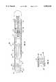
- FIG. 12is a schematic illustration in longitudinal section showing an actively controlled rotary steerable drilling system representing the preferred embodiment of the present invention and having a turbine driven alternator, with the electric current output thereof being utilized to drive an electric motor having a motor output shaft connected in driving relation with an omnidirectional bit shaft support and positioning mechanism for maintaining the longitudinal axis of the bit shaft geostationary and at a predetermined angle relative to the axis of rotation of the tool collar;
- FIG. 13is a schematic illustration in section showing a turbine which may be utilized for the turbines of FIGS. 12 and 14, and illustrating turbine stator positioning relative to the rotor for controlling the efficiency and power output of the turbine;
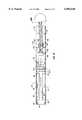
- FIG. 14is a schematic longitudinal sectional view of an actively controlled rotary steerable drilling system representing an alternative embodiment of the present invention and showing a turbine connected in driving relation with an alternator and with the turbine and alternator being located in the same section of the tool collar as the motor, offsetting mandrel and bit shaft and further showing a mechanism providing omnidirectional pivotal support within the tool collar for the bit shaft;
- FIG. 15is a schematic longitudinal sectional view of an actively controlled rotary steerable drilling system representing an alternative embodiment of the present invention and showing a turbine connected in driving relation with a gear box via a turbine drive shaft extending through the electronics, sensors and brake section of the drilling system and with the output of the gear box connected in driving relation with an offsetting mandrel for accomplishing geostationary positioning of the axis of a bit shaft;
- FIG. 16is a partial longitudinal sectional view illustrating a further alternative embodiment of the present invention showing a rotary steerable drilling tool having a hydraulically powered system for orienting the bit shaft of the tool during drilling operations;
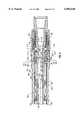
- FIG. 17is a longitudinal sectional view showing the lower portion of the actively controlled rotary steerable drilling system of FIG. 12 in greater detail;
- FIG. 18is a longitudinal sectional view showing the upper portion of the actively controlled rotary steerable drilling system of FIG. 12 in greater detail;
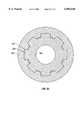
- FIG. 19is a transverse sectional view taken along line 19--19 of FIG. 17;
- FIG. 20is a transverse sectional view taken along line 20--20 of FIG. 18;
- FIG. 21is a partial transverse sectional view of an alternative embodiment of the present invention showing a spline type universal joint for omnidirectional support of the bit shaft within the tool collar and for imparting driving rotation to the bit shaft for rotation of the drill bit;
- FIG. 22Ais a schematic illustration in transverse section showing the bit shaft positioning rings relatively positioned for straight drilling and showing coincidence of the longitudinal axes of the bit shaft and tool collar for zero angulation of the bit shaft;
- FIG. 22Bis a sectional view taken along line 22B--22B of FIG. 22A and showing the coaxial relationships of the bit shaft positioning rings for straight drilling;
- FIG. 22Cis a schematic illustration in transverse section showing the bit shaft positioning rings located at positions for maximum offset and thus maximum lateral positioning of the centerline of the bit shaft for maximum angulation of the bit shaft relative to the tool collar;
- FIG. 22Dis a sectional view taken along line 22D--22D of FIG. 22C showing the offset axial relationships of the bit shaft positioning rings for maximum offset and thus drilling at maximum rate of curvature;
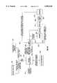
- FIG. 23is a block diagram schematic illustration showing the control architecture of the preferred embodiment of the rotary steerable drilling system of the present invention, showing the concept of turbine powered braking and brake control for the purpose of steering the drill bit that is oriented by the tool;
- FIG. 24is a block diagram schematic illustration showing the control architecture of an alternative embodiment of the present invention having a drilling fluid powered turbine and brake for controlling bit shaft positioning relative to the tool collar and a position signal responsive brake controller for controlling the brake and for controlling turbine efficiency; and
- FIG. 25is a transverse sectional view taken along line 25--25 of FIG. 21 showing a splined drive connection between the bit shaft and drilling tool collar.
- a wellbore 10is shown being drilled by a rotary drill bit 12 that is connected at the lower end of a drill string 14 that extends upwardly to the surface where it is driven by the rotary table 16 of a typical drilling rig (not shown).
- the drill string 14typically incorporates a drill pipe 18 having one or more drill collars 20 connected therein for the purpose of applying weight to the drill bit 12.
- the wellbore 10is shown as having a vertical or substantially vertical upper section 22 and a deviated, curved or horizontal lower section 24 which is being drilled under the control of an actively controlled rotary steerable drilling tool shown generally at 26 which is constructed in accordance with the present invention.
- a lower section of drill pipe 28may be used to connect the drill collars 20 to the drilling tool 26 so that the drill collars will remain in the vertical section 22 of the wellbore 10.
- the lower section 24 of the wellbore 10will have been deviated from the vertical section 22 by the steering activity of the drilling tool 26 in accordance with the principles set forth herein.
- the drill string immediately adjacent the rotary steerable drilling toolmay incorporate a flexible sub, also shown in FIGS. 10 and 11, which can provide the rotary steerable drilling system with enhanced accuracy of drilling.
- drilling fluid or "mud”is circulated by surface pumps down through the drill string 14 where it exits through jets that are defined in the drill bit 12 and returns to the surface through an annulus 30 between the drill string 14 and the wall of the wellbore 10.
- the rotary steerable drilling tool 26is constructed and arranged to cause the drill bit 12 to drill along a curved path that is designated by the control settings of the drilling tool 26.
- the angle of the bit shaft supporting the drill bit 12 with respect to the tubular collar of the drilling tool 26is maintained even though the drill bit and drilling tool are being rotated by the drill string 14, thereby causing the drill bit to be steered for drilling a deviated wellbore.
- Steering of the drilling toolis selectively accomplished from the standpoint of inclination and from the standpoint of azimuth, i.e., left and right. Additionally, the settings of the steerable drilling tool 26 may be changed as desired to cause the drill bit to selectively alter the course of the wellbore being drilled to thereby direct the deviated wellbore for precision steering of the drill bit and thus precision control of the wellbore being drilled.
- FIGS. 2 and 3are schematic illustrations showing the rotary steerable drilling system of the present invention located within a wellbore 10 being drilled and further showing a method of drilling wherein a mud motor M is utilized within the rotary drill string either above the steerable drilling tool as shown in FIG. 2 or below the steerable drilling tool as shown in FIG. 3.
- This unique arrangementpermits rotation of the drill string 14 at a desired rotational speed and rotation of the mud motor output at a different rotational speed to provide for optimum drilling characteristics without causing excessive fatigue of the drill string.
- the rotational speed of the drill bitis the same as that of the drill string.
- the rotary table of the drilling rigcan be set at an optimum rotational speed for the drill string and the mud motor will be capable of adding rotational speed to the drill bit that is driven by the mud motor output.
- the rotary tablecan be operated at a rotational speed of 50 revolutions per minute for example, to allow breaking of the friction between the borehole and the drill string, a rotational speed that will not limit the service life of the drill string due to fatigue, while the rotational speed of the drill bit can be increased by the mud motor to provide for enhanced drilling characteristics to thus enable extended reach drilling.
- the rotary steerable drilling systemcan be operated at the mud motor controlled rotational speed when located below the mud motor and can be rotated at drill string speed if connected directly to the drill string. If the mud motor is located below the rotary steerable drilling tool, its rotary output is imparted directly to the drill bit. Steering characteristics during drilling will have greater precision when the mud motor is located above the rotary steerable drilling tool for the reason that the distance from the rotary steerable drilling tool to the drill bit is a principal controlling factor from the standpoint of steering precision.
- the rotary steerable drilling system of the present inventionmay be connected in a drill string in association with other drilling tools such as mud motors, as described above, for controlling rotational speed and torque, and thrusters for controlling weight on bit.
- the arrangement of these components within a drill stringmay be selected by drilling personnel according to a wide variety of characteristics, such as the tightness of the curved wellbore section being drilled, the characteristics of the formation being drilled, the character of drilling equipment being employed for drilling, and the depth at which drilling is taking place.
- the schematic illustration of FIG. 4shows the rotary steerable drilling tool 26 connected in the drill string 14 along with a drilling fluid powered thruster T, which is provided to control weight on bit.
- the thrusteris comprised mainly of a hydraulically controlled piston, the lower part of the bottom hole assembly being connected to the piston.
- the coupling 27 between the rotary steerable drilling tool 26 and the thruster Tmay be a simple pipe coupling, or a tool section permitting integration of the control features, electronic, hydraulic, or a combination of electronic and hydraulic controls, between the rotary steerable drilling tool and the thruster. If desired, the coupling 27 may take the form of the flexible sub shown in FIGS. 10 and 11. As shown in FIG. 5, a thruster T is connected below the rotary steerable drilling tool 26 and this is positionable in angulated relation with the collar of the drilling tool 26 by adjusting the position of the bit shaft of the tool.
- the bit shaftprovides support for the thruster while the thruster provides support for the drill bit as well as controlling weight on bit.
- the arrangement of the rotary steerable drilling system 26 and the thruster Tis as shown in FIG. 4.
- a mud motor Mis connected to the drill string 14 above the thruster to thus provide for rotation of the thruster and the collar of the rotary steerable drilling tool at a speed of rotation that is different from the rotational speed of the drill string, while at the same time controlling weight on bit.
- the schematic illustration of FIG. 7shows a mud motor M connected above the rotary steerable drilling tool 26 and shows a thruster T connected in the drill string 14 above the mud motor.
- FIG. 8shows the rotary steerable drilling tool connected to the drill string 14 and having a mud motor M connected to the geostationary bit shaft of the tool and thus subject to angulation relative to the tool collar along with the bit shaft.
- a thruster Tis located below the mud motor M for supporting the drill bit and for controlling weight on bit. The thruster T is positioned relative to the collar of the rotary steerable drilling tool 26 by the output shaft of the mud motor M and the mud motor is positioned for controlled steering by the bit shaft of the rotary steerable drilling tool.
- FIG. 9shows the rotary steerable drilling tool 26 connected to the drill string 14 and having a thruster T supported and oriented by the bit shaft relative to the collar of the tool.
- a mud motor Mis positioned below the thruster so that its output shaft both supports and drives the drill bit.
- the drill bitis thus steered by the rotary steerable drilling tool and is rotationally driven by both the rotary speed of the drill string and the rotary speed of the mud motor output shaft. This enables the drill bit to be rotated at a speed that is greater than or equal to the rotational speed of the drill string, while at the same time weight on bit is controlled by the thruster.
- the thruster Tmay be provided with a control valve D1 in the fluid circuit thereof while a control valve D2 may be provided in the fluid circuit of the mud motor M.
- These control valvesare selectively positioned by the control circuitry of the rotary steerable drilling system, indicated schematically by the line C, to thus permit the thruster and/or the mud motor to be integrated into the control system of the rotary steerable drilling system.
- the mud motor and thrusterare subject to feedback responsive control in the same manner as the rotary steerable drilling system.
- the control valve D2 in the mud motor Mcan be controlled by the rotary steerable drilling system to control the rotary speed of the output shaft of the mud motor and to thus control torque at the drill bit.
- the control valve D1 of the thrusteris selectively positioned by the control system of the rotary steerable drilling system to control weight on bit.
- the rotary steerable drilling system of the present inventionprovides for effective steering of the drill bit and for enhanced drilling characteristics by efficiently controlling torque at the drill bit and controlling weight on bit to thus promote extended reach drilling.
- FIGS. 10 and 11show a drill string 14 having an actively controlled rotary steerable drilling system 26 connected therein for steering a bit shaft having a drill bit 12 connected thereto.
- the drill string 14also incorporates a mud motor M for increasing the speed of rotation of the drill bit 12 and a flexible sub 28 for the purpose of enhancing the precision of steering that is accomplished by the rotary steerable drilling system.
- the flexible sub 28also accomplishes selective decoupling of the rotary steerable drilling system from the drill string to thus enhance the steering capability thereof.
- an actively controlled rotary steerable drilling system constructed in accordance with the principles of the present inventionis shown generally at 26, as mentioned above, and represents the preferred embodiment.
- the actively controlled rotary steerable drilling system 26has a tubular collar 32 which at its upper end defines an internally threaded section 34 enabling its connection directly to the flexible sub 28 or to the rotary output shaft of a mud motor and thruster, depending upon the manner by which the steerable drilling tool 26 is to be employed.
- FIG. 12an actively controlled rotary steerable drilling system constructed in accordance with the principles of the present invention is shown generally at 26, as mentioned above, and represents the preferred embodiment.
- the actively controlled rotary steerable drilling system 26has a tubular collar 32 which at its upper end defines an internally threaded section 34 enabling its connection directly to the flexible sub 28 or to the rotary output shaft of a mud motor and thruster, depending upon the manner by which the steerable drilling tool 26 is to be employed.
- an electromagnetic induction system 36 and an electrical wire communication link 38to provide for communication of signals from the rotary steerable drilling tool 26 to an uphole MWD system to send downhole data back to the surface in real time and to facilitate communication of control signals from drilling control equipment at the surface to the tool during drilling operations.
- the collar 32also defines an electronics and sensor support section 40 having therein various sensor equipment.
- the support section 40may define a receptacle 42 within which is located a magnetometer, accelerometer, and gyroscopic sensor having the capability of providing electronic output signals that are utilized dynamically for steering of the tool.
- a number of electronic components of the actively controlled rotary steerable drilling system 26may also be incorporated within the electronics and sensor support section 40.
- a formation resistivity measurement system 41may be located within the collar 32 for rotation along with the collar and will incorporate vertically spaced transmitters and receivers to enable electromagnetic signals to determine formation resistivity.
- the method and apparatus for measuring resistivity of the earth formation being drilled, and to do so while rotary drilling operations are in progress,may conveniently take the form that is set forth in U.S. Pat. No. 5,594,343, which patent is incorporated herein by reference.
- the apparatus and electronics of the resistivity measurement systemmay rotate with the collar 32 or it may rotate with other components of the actively controlled rotary steering tool.
- the system for resistivity measurementmay also be physically located at any other desired location within the tool 26 as desired to enhance manufacture or use of the rotary steerable drilling system.
- sensing and measuring systemsmay also be incorporated within the electronics and sensor support section 40, including, for example, a gamma ray measurement system or a sonic imaging system.
- the drilling tool 26may also incorporate rotational speed sensing equipment, bit shaft vibration sensors and the like.
- electronic data processing systemsmay also be included within the electronics package of the tool for receiving and processing various data input thereto and providing signal output that is used for steering control and for controlling other factors encountered during well drilling.
- the electronic data processing systemsmay be selectively located within the tool so as to be rotatable along with the tool collar or counter-rotatable within the tool collar along with the bit shaft and its operational components.
- a fluid energized turbine mechanism shown generally at 48having a stator 50 which is preferably disposed in fixed relation with the tubular collar 32 and a rotor 52 that is mounted for rotation relative to the stator 50.
- the relative positions of the rotor 52 and stator 50are adjustable, either or both of the rotor and stator may be subject to position controlling movement, for the purpose of controllably varying the efficiency and thus the power output of the turbine 48.
- the rotor 52is provided with a turbine output shaft 54 which is disposed in driving relation with an alternator 56 via a transmission 58.
- turbine efficiency controlcan be achieved by mounting the stator 50 so as to be controllably movable by the drilling system electronics responsive to turbine output demand.
- the turbinemay also be braked electrically to limit free spin thereof, thus increasing the power that is available from the turbine.
- the heat that is developed during such electric brakingwill be dissipated efficiently by the drilling fluid which flows through the tool.
- the drilling fluid flow through the toolalso serves to cool the various internal components of the tool, such as the electronics package, the alternator and the bit shaft positioning motor.
- the alternator 56as shown in FIG. 14, functions as resistance to turbine output and because of its resistance, the alternator 56 is utilized as an electromagnetic brake.
- the alternator 56is provided with a transmission mechanism 58 which permits the turbine 48 to operate at optimum rotational velocity for efficient operation of the alternator.
- the alternator 56provides an electrical output that is electrically coupled with the operational and control circuitry of an electric motor 60 so that the electrical energy generated by the turbine driven alternator 56 is employed to drive the electric motor 60.
- a gear box or transmission 61 driven by the electric motor 60has its rotary output connected in driving relation with an offsetting mandrel 62 which is rotatably driven by the internal rotor of the electric motor 60 and to which is fixed a rotary drive head 64 having an eccentrically located positioning receptacle 66 therein which receives an end 68 of a bit shaft 70.
- the offsetting mandrel 62 and the rotary drive head 64are counter-rotated with respect to the rotation of the collar 32 to maintain the axis of the bit shaft 70 geostationary during drilling.
- the bit shaft 70is mounted for rotation within the tubular collar 32 intermediate its extremities for omnidirectional movement about a pivot-like universal joint 72 which is preferably of the ball pivot configuration and function shown in FIGS.
- Certain components of the electronic data processing systemsmay be located geostationary in the rotary drive head 64.
- the accelerometers, magnetic sensors and gyroscopic sensormay be located in the rotary drive head 64.
- An inclination sensoris located on the rotary drive head 64 to thereby provide a measurement reflecting the position of the drive head within the borehole.
- the precise position of the rotary components of the drilling toolestablish a known position index from which steering correction is determined.
- position indicating sensorsbe located in geostationary relation with respect to the rotary drive system for the bit shaft.
- the rotary drive head 64 of the offsetting mandrel 62may be provided with various position indicators, such as accelerometers, magnetometers, and gyroscopic sensors which are disposed in fixed relation with the rotary drive head 64 or any other component that is rotatable concurrently therewith.
- FIG. 14an alternative embodiment of the present invention is shown generally at 26A, wherein like components, as compared to the embodiment of FIG. 12, are shown by like reference numerals.
- the basic difference in the embodiments of FIGS. 12 and 14is the location of the turbine 48 and alternator 56 with respect to the electronics and sensor support section 40 of the rotary steerable drilling system 26.
- the electronics and sensor support section 40is located above the turbine 48.
- the stator 50 and rotor 52 of the turbine 48 of FIG. 14can be relatively adjustable, with the stator 50 preferably being linearly movable within the collar 32 relative to the rotor 52 to adjust the efficiency and thus the power output of the turbine.
- the turbine output shaft 54is connected in driving relation with an alternator 56 which may have a transmission 58 for permitting the turbine and alternator to run at appropriate speeds for optimum torque output.
- the heat that is generated by motor operation and braking and by the system electronicswill be continually dissipated by the drilling fluid that flows continuously through the rotary steerable drilling system.
- the alternator 56powers an electric motor 60.
- the output shaft of the electric motor 60functions as an offsetting mandrel 62 and is provided with a rotary drive head 64 having a positioning receptacle 66 located eccentrically therein and receiving the driven end 68 of a bit shaft 70 for rotating the bit shaft about its universal joint support 72 in the manner described above in connection with the preferred embodiment of FIG. 12.
- the omnidirectional or universal joint support 72 for the bit shaft 70may be of the ball type as shown in FIGS. 17 and 19, or of the splined type as shown in FIGS. 21 and 25.
- the rotary steerable drilling system 26Bincorporates an elongate, tubular tool collar 32 which is adapted for connection to a drill string or rotary components of a drill string so that the tool collar 32 is rotated during well drilling operations.
- a turbineshown generally at 48 is mounted and includes a rotor and stator assembly, with the rotor being driven by drilling fluid flow 49 through the tool collar.
- the electronics and sensors and the brake mechanism 35 of the rotary steerable drilling systemare secured within the tool collar 32 by mounting elements 33 so that an annulus 37 exists which defines a flow path through which drilling fluid is allowed to flow. Heat that is developed in the electronics and sensors and brake mechanism 35 during operation is carried away by the drilling fluid that flows continuously through the rotary steerable drilling system 26B.
- the rotor of the turbineimparts driving rotation to a drive shaft which is rotated at a speed that is optimum for turbine operation, though typically excessive for offsetting mandrel and bit shaft rotation and having a torque output that is insufficient for geostationary bit shaft axis positioning.
- a gear train 39also centrally mounted within the tool collar 32, has its input mechanism connected to the turbine driven shaft and has its output connected to impart driving rotation to an offsetting mandrel 62.
- the offsetting mandrel 62in the same manner as is shown in FIG. 14, is provided with a rotary drive head 64 defining an eccentric positioning receptacle 66 which receives the upper end 68 of a universally rotatable bit shaft 70.
- the bit shaft 70is mounted within the tool collar 32 by a universal joint 72 in the manner and for the purpose described above.
- a turbine 48is mounted within the tool collar 32 and incorporates a stator 50 and rotor 52, with the output shaft 54 of the rotor coupled in driving relation with a hydraulic pump 53.
- the turbine 48may be mounted within the tool collar 32 above the electronics and sensor support section 40 as shown, or below this section.
- a hydraulic motor 55is mounted within the tool collar 32 and is operated by pressurized hydraulic fluid from the pump 53 for driving the offsetting mandrel 62.
- the hydraulic motor 55may incorporate a braking system or have a braking system in combination therewith so as to function as a motor and brake in the manner and for the purpose described herein. Additionally, the rotary output of the hydraulic motor 55 may be altered by a gear box 57 so as to provide the desired rotational speed and power for efficient steering while drilling.
- FIGS. 17 and 18the mechanism of the actively controlled rotary steerable drilling tool 26 of FIG. 12 is shown in detail and represents the preferred embodiment of this invention.
- a bit shaft support receptacle 82which is defined by a tubular extension 84 of the tool collar 80.
- a tubular sleeve 86having a thrust ring 90 which is spring loaded against a bit shaft rotation ring 94 and defines a spherical surface segment 92.
- Bit shaft rotation ring 94is positioned about the bit shaft 96 and defines a corresponding spherical surface segment 98 that is in supported engagement with the spherical surface segment 92 of the thrust ring 90, thus causing the thrust ring 90 to transfer thrust force from the bit shaft rotation ring 94 to the tubular tool collar 80 while at the same time allowing the bit shaft to pivot about the pivot point 99 about which the spherical surface segment 92 is generated.
- a segmented retainer 97is positioned within a circular retainer groove 101 of the bit shaft 96 and is secured within the circular retainer groove 101 by an overlying circular section of the bit shaft rotation ring 94.
- a second thrust ring 100is positioned about the bit shaft 96 and defines a spherical surface segment 106, in turn centered about pivot point 99, facing in the same direction as the spherical surface segment 92 of the thrust ring 90.
- the second thrust ring 100defines a planar thrust transmitting shoulder surface 102 which is disposed in thrust transmitting engagement with the bit shaft rotation ring 94 and with the segmented retainer 97.
- a second bit shaft rotation ring 104is positioned about the bit shaft 96 and defines a spherical surface segment 107 that is concentric with the spherical surface segment 98 and is disposed in thrust force transmitting engagement with the spherical surface segment 106 of the thrust ring 100 so as to permit rotation of the bit shaft 96 about the pivot point 99 about which both the spherical surface segments 92 and 106 are generated.
- the bit shaft rotation ring 104is retained in engagement with the thrust ring 100 by means of a spring that is positioned by a first ball support ring 108.
- the thrust rings 90 and 100can change location and diameters with respect to pivot point 99 without departing from the scope of the present invention.
- the chain of thrust rings between the tool collar 80 and the bit shaft 96is a preferred embodiment mechanism which functions to transmit axial forces from the tool collar 80 to the bit shaft 96, and to contain bit shaft 96 axially and radially within shaft support receptacle 82.
- This bi-directional force transmission embodimentallows for the bit shaft 96 to pivot about the pivot point 99 and permits the axis of the bit shaft to remain geostationary while rotating in a specified direction.
- Alternative methods of transmitting forcesinclude angular contact radial bearings, which would also allow for pivoting of the bit shaft about pivot point 99, or a combination of tapered thrust rings and angular contact radial bearings which would similarly allow force transmission and pivoting.
- the first ball support 108 ringdefines a circular groove segment surface 110 having a plurality of pockets in close fitting relation with a plurality of ball bearings 112 that are received within spherical bearing grooves 114 in the bit shaft 96.
- Ball support ring 108is rotationally constrained with respect to the tool collar 80 using a plurality of keys or splines as shown at 211 in FIG. 19.
- a second circular ball support ring 116is positioned so that a circular groove segment surface 118 thereof defines a plurality of pockets in loose fitting relation with the ball bearings 112 and is also rotationally constrained with respect to the tool collar 80 by splines 211.
- the second ball support ring 116is in turn supported by a retainer sleeve 120 which is threadedly secured to the tubular extension 84 of the tool collar 80.
- FIG. 25An alternative embodiment for transmitting torque between the collar 182 and the bit shaft 188 is shown in FIG. 25 where collar 182 transmits torque to the bit shaft 188 through flat or circular contact surfaces 301 of bit shaft extensions 300.
- a plurality of bit shaft extensions 300can exist, either as integral parts of the bit shaft 188 or as additional pieces retained in the bit shaft.
- the combination of ball support ring 108, ball bearings 112 and spherical bearing grooves 114 shown in FIGS. 17 and 19defines a means of transmitting drilling torque from the tool collar 80 to the bit shaft 96, and in turn to the drill bit.
- the oversize groove segment surfaces 110 and 118 in ball support rings 108 and 116allow for pivoting of the bit shaft 96 about the pivot point 99 while at the same time transmitting drilling torque from the tool collar 80 to the bit shaft 96.
- this embodimenttransmits thrust and torque loads between the tool collar 80 and the bit shaft 96 while allowing the bit shaft axis to remain geostationary while being rotated by the tool collar 80 to achieve drilling in a selected direction.
- the tubular tool collar 80is provided with means for sealing outside drilling mud from inside lubricating and protecting oil about the universal joint.
- One suitable means for accomplishing such sealingis a bellows type sealing assembly 126 which creates an effective barrier to exclude drilling fluid from the universal joint assembly while accommodating pivotal movement of the bit shaft 96 relative to the tool collar 80.
- FIGS. 22A-DA preferred method for creating this offset is shown in FIGS. 22A-D, where the offsetting mandrel is attached rotationally to an outer ring 400 having an offset internal surface 401, this circular internal surface having a centerline at an offset and at an angle to the outside diameter of the inner ring 406 as is more clearly evident in FIG. 22B.
- FIG. 22A-DA preferred method for creating this offset is shown in FIGS. 22A-D, where the offsetting mandrel is attached rotationally to an outer ring 400 having an offset internal surface 401, this circular internal surface having a centerline at an offset and at an angle to the outside diameter of the inner ring 406 as is more clearly evident in FIG. 22B.
- the offsets from the outer and inner ringssubtract, which causes the center of the bit shaft axis 402 (aligned to internal diameter 407 of the inner ring 406) to be aligned with the longitudinal axis of the offsetting mandrel. Consequently, as depicted in FIGS. 22A and 22B, the center 405 of the inner ring (bit shaft) 406 is coincident with the center 404 of the outer ring (offsetting mandrel) 404, thereby causing the rotary steerable drilling tool to drill a straight wellbore.
- the bit shaft positioning ringscan have any relative rotational positioning between the ring positions of FIG. 22A and 22B and the ring positions of FIGS.
- the angled relation of the longitudinal axis of the bit shaft with respect to the longitudinal axis of the drill collaris variable between 0° and a predetermined maximum angle depending upon the relative positions of the bit shaft positioning rings.
- These ringscan be rotated with respect to each other by various mechanical or electrical means, including but not limited to a geared motor.
- one of the rings of the offsetting mechanismcan be defined by the eccentric receptacle 134 of the concentric drive element 132 at the lower end of the offsetting mandrel 130 as shown in FIG. 17.
- the eccentric receptacle 134 of the offsetting mandrel 130is rotated by the concentric drive element 132 the eccentric receptacle 134 subjects the upper end of the bit shaft 96 to lateral positioning with respect to the axis of rotation of the offsetting mandrel 130 as determined by the relative positions of the rings 400 and 406 of FIGS.
- the bit shaft 96to be rotated about its universal support so that its longitudinal axis 133 becomes positioned in angular relation with the axis of rotation 135 of the tubular tool collar 80 as shown in FIG. 17.
- the offsetting mandrel drive motorwhether electric, hydraulic or a drive turbine, counter-rotates the tubular drive shaft and the concentric drive element of the offsetting mandrel 130 at the same rotational frequency as that of the tubular tool collar 80, the concentric drive element 132 maintains the longitudinal axis 133 of the bit shaft 96 at a geostationary angle with respect to the axis of rotation of the tubular tool collar 80.
- bit shaft 96Since the tool collar 80 is in direct rotational driving relation with the bit shaft 96, rotation of the tool collar 80 by the drill string or by a mud motor connected to the drill string, causes the bit shaft 96 to rotate the drill bit supported thereby at the angle of inclination and azimuth that is established by such orientation of the bit shaft. This causes the drill bit to drill a curved borehole that is permitted to continue its curvature until such time as a desired borehole inclination has been established. The drilling tool is then controlled by signals from the surface or by feedback signals from its various on-board control systems such that its steering control mechanism is neutralized and the resulting borehole being drilled will continue straight along the selected angle of inclination and azimuth that has been established by the curved borehole.
- the "ring within a ring" bit shaft adjustment featurefacilitates bit shaft angulation adjustment as drilling operations are in progress, without necessitating cessation of drilling or withdrawal of the drilling equipment from the wellbore.
- the offsetting mandrel 130is provided with an offset flow passage section 150 which directs flowing drilling fluid from the flow passage 152 of the tubular drive shaft and permits unrestricted flow of drilling fluid through the offsetting mandrel 130 even when the bit shaft 96 has been positioned thereby for its maximum angle with respect to the tool collar 80.
- a tubular pressure compensator 154is positioned about the offsetting mandrel 130 as shown in FIG. 18 and separates an oil chamber 158 from an annular chamber 159 and is intended to contain a protective oil medium within the oil chamber 158.
- the pressure compensator 154is connected and sealed to the lower end 164 of a tubular electronics carrier 166 which is also shown in the cross-sectional illustration of FIG. 20.
- the tubular electronics carrier 166defines a weighted section 168 extending circumferentially in the range of about 90 degrees as shown in FIG. 20 and providing for retention of various system control components such as a magnetometer, a gyroscopic device, an accelerometer, a resistivity sensor arrangement and the like. Additionally, the weighted section 168 provides counterbalancing forces during shaft rotation to offset the lateral loads of rotary bit shaft actuation and thus minimize vibration of the rotary steerable drilling tool during its operation.
- a partial circumferential space 170is defined internally of the tool collar 80 and externally of the tubular electronics carrier 166 and provides for location of the system electronics 172 of the rotary steerable drilling tool.
- the system electronics 172 and the various system control componentsare counter-rotated by the drive motor at the same rotational speed as that of the tool collar 80 so that the electronics and system control components are essentially geostationary during drilling operations.
- an alterative embodiment of the present invention having a splined universal jointis shown generally at 180, having a tool collar 182 that is adapted for connection to a drill string for rotation in the manner described above.
- the tool collar 182defines an elongate tubular extension 184 which defines an internal receptacle 186 having an omnidirectional drive connection or universal joint located therein for permitting angulation of the bit shaft 188 with respect to the tool collar 182 for geostationary positioning of the bit shaft and drill bit for drilling a curved wellbore.
- a shoulder within the internal receptacle 186provides support for a thrust ring 190 having a spherical surface segment 192.
- a bit shaft rotation ring 194is located about the bit shaft 188 and defines a spherical surface segment 196 that is disposed in force transmitting and pivotally movable relation with the thrust ring 190.
- the bit shaft rotation ring 194defines a circular recess within which is positioned a circular thrust flange 200.
- a second thrust ring 204also encompassing the bit shaft 188, is positioned with one axial end thereof disposed in abutment with the circular thrust flange 200 and the bit shaft rotation ring 194.
- the lower circular face of the second thrust ring 204is defined by a circular spherical surface segment 206, being a segment of a sphere that is concentric with the spherical surface segment 192.
- the circular spherical surface segment 206is engaged by an external upwardly facing spherical surface segment 207 of a lower thrust ring 208 so that positioning of the longitudinal axis of the bit shaft 188 relative to the longitudinal axis of the tool collar 182 occurs about pivot point 209.
- the system electronics 240incorporate a programmable electronic memory and processor 242 which is programmed with appropriate algorithms for desired toolface calculation, establishing the borehole curvature that is desired to steer the borehole being drilled to a subsurface zone of interest.
- the system electronicsis programmable downhole and programmable during drilling to enable drilling personnel to selectively steer the drill bit as drilling is in progress.
- Data from magnetometers 244provides the system electronics with the position of the tool collar with respect to the earth's magnetic field.
- Data from one or more gyroscopic sensors 246provides the system electronics with the angular velocity of the output shaft, i.e., the bit shaft of the rotary steerable drilling system.
- the data from the magnetometers and gyroscopic sensorsis available to the system electronics by selection of an OR gate circuit 248 which is capable of automatic actuation by the system electronics and selective actuation by control signals from the surface.
- At least one and preferably a plurality of accelerometers 250are provided within the rotary steerable drilling system and provide data input to the system electronics that identifies the position of the tool collar in real time with respect to gravity.
- the system electronics 240calculates the instantaneous desired angle between the scribe line of the tool collar and the scribe line of the offsetting mandrel and transmits signals to a motor controller 252 representing the desired angle.
- An angular position sensor 260is located within the tubular tool collar and is positioned in non-rotatable relation about a portion of the drive shaft of the brushless direct current motor/brake 256 which is capable of rotationally driving the offsetting mandrel or rotationally braking the offsetting mandrel as controlled by the system electronics 240 responsive to various signal input.
- the purpose of the angular position sensor or resolver 260is to identify the real time position of the motor/brake shaft at any given point in time relative to the tool collar and to communicate motor/brake position signals to the motor controller 252 via signal conductor 257.
- the motor shaftis driven in a rotary direction that is counter to the rotation of the tubular tool collar by the drill string to which the tubular tool collar is connected and at the same frequency as the rotational frequency of the tool collar.
- the angular position sensor or resolvermay take the form that is shown and described in U.S. Pat. No. 5,375,098, which is incorporated herein by reference.
- the output shaft of the motor/brake 256drives a gear box 262 to thus permit the motor to operate at its optimum rotational speed for desired torque and to permit the output shaft 258 to be rotated in synchronous relation with the speed of tool collar rotation.
- a switch/trigger 264such as a Hall effect sensor or other trigger circuit, is provided which, when triggered, provides the actual position of the offsetting mandrel with respect to the tool collar.
- the signals of the switch/triggerare input to the motor controller 252 via signal conductor 265 to identify the bit shaft position change, if any, that is necessary for the drill bit to follow a programmed curved track during steerable drilling operations.
- the angular position sensor 260may be mounted on the output shaft of the gear box 262.
- FIG. 24the system control architecture for the alternative embodiment of FIG. 14 is shown wherein the motive force for counter-rotational control of the offsetting mandrel and thus geostationary positioning of the axis of rotation of the bit shaft is achieved by a drilling fluid powered turbine and brake and is controlled in part by controlling the efficiency of the turbine. That portion of the system control architecture, for establishing a control signal representing the desired angle between the scribe line of the tool collar and the scribe or reference line of the offsetting mandrel is substantially of the form that is described above in connection with FIG. 23.
- This angle control signalis supplied to a brake controller 266 which also receives position signal input via trigger signal conductor 268 from a trigger circuit 270 and via a resolver signal conductor 272 from a resolver 274.
- the control signal output of the brake controller 266is supplied to an efficiency control circuit 276 for controlling the efficiency of the turbine 278 and is supplied to a brake 280 for controllably braking the output shaft of the turbine 278 and thus for controlling rotation of the shaft that is sensed by the resolver.
- a gear box 280may have its input connected with the turbine driven and braked shaft and may be appropriately geared to drive its output shaft 282 within the desired speed range for efficient bit shaft positioning and efficient curved borehole drilling.
- An alternative optionis to include within the system a turbine control mechanism capable of modifying the power produced by the turbine by changing its efficiency.
- this featurecan be achieved by housing the rotor 52 of the turbine 48 in a stator 50 defining a conical surface 53, and by moving the stator 50 linearly with respect to the rotor 52, thus defining a selectively variable turbine.
- the mounting system for the turbine 48 within the rotary steerable drilling toolwill cause the stator 50 to be mounted within the tool collar for controlled linear movement responsive to the system electronics and brake controller.
- the mounting system for the statoris actuated by the control electronics of the drilling tool, i.e., position signal responsive brake controller 266 and efficiency control 276 as shown in FIG. 24, so that its adjustable positioning can be achieved with the drilling tool located downhole and can be achieved while the drilling tool is in operation to effectively maintain rotational speed and torque of the turbine within desired limits for effective operation.
- control electronics of the drilling tooli.e., position signal responsive brake controller 266 and efficiency control 276 as shown in FIG. 24, so that its adjustable positioning can be achieved with the drilling tool located downhole and can be achieved while the drilling tool is in operation to effectively maintain rotational speed and torque of the turbine within desired limits for effective operation.
- Such a turbine control mechanismwould be used to reduce the power output of the turbine at higher flow rates. At lower flow rates the turbine would work at its maximum efficiency to insure that the turbine power is always larger than the resistive power. Since the turbine control mechanism would mainly respond to flow rate variations its response bandwidth need not be very high.
Landscapes
- Engineering & Computer Science (AREA)
- Geology (AREA)
- Life Sciences & Earth Sciences (AREA)
- Mining & Mineral Resources (AREA)
- Environmental & Geological Engineering (AREA)
- Fluid Mechanics (AREA)
- Physics & Mathematics (AREA)
- General Life Sciences & Earth Sciences (AREA)
- Geochemistry & Mineralogy (AREA)
- Mechanical Engineering (AREA)
- Earth Drilling (AREA)
- Fluid-Driven Valves (AREA)
- Fluid-Pressure Circuits (AREA)
- Electrical Discharge Machining, Electrochemical Machining, And Combined Machining (AREA)
- Perforating, Stamping-Out Or Severing By Means Other Than Cutting (AREA)
Abstract
Description
1. Field of the Invention
This invention relates generally to methods and apparatus for drilling wells, particularly wells for the production of petroleum products, and more specifically concerns an actively controlled rotary steerable drilling system that can be connected directly to a rotary drill string or can be connected in a rotary drill string in assembly with a mud motor and/or thruster and/or flexible sub to enable selective decoupling of the actively controlled rotary steerable drilling system from the rotary drill string, such as for mud motor powered drilling, with or without drill string rotation, and to enable precision control of the direction of a bore being drilled by a drill bit and precision control of the rotary speed, torque and weight on bit being imparted to the drill bit. For mud motor speed and torque control, a controllable dump valve is provided in the fluid circuitry of the mud motor to controllably dump or divert a portion of the drilling fluid flow from the fluid circuit of the mud motor to the annulus or to bypass a portion of the drilling fluid flow past the rotor of the mud motor. This mud motor dump or bypass control valve can be automatically operated responsive to sensor signals from the rotary steerable drilling system or can be operated responsive to signals from the surface or both. For controlling weight on bit a drilling fluid powered thruster is provided in the drill string and is located above or below the rotary steerable drilling system. The thruster has a similarly controllable dump or bypass valve in its drilling fluid circuitry which is selectively adjustable by the control circuitry of the rotary steerable drilling system for the purpose of controlling the downward mechanical force, i.e., weight of the drill bit against the formation being drilled. The dump or bypass valves of the mud motor and thruster are thus both independently controlled downhole by the control system of the rotary steerable drilling tool responsive to feedback signals from various sensors and can be selectively controlled by telemetry from the surface as well. This invention also concerns an actively controlled rotary steerable drilling system incorporating a turbine powered electric motor drive mechanism for geostationary positioning of a drill bit during its rotation by the rotary drill string, mud motor, or both and having the capability for selective employment of the electric motor as a brake when the torque of the bit/formation interaction is prevalent as compared to internal friction.
2. Description of the Related Art
An oil or gas well often has a subsurface section that is drilled directionally, i.e., inclined at an angle with respect to the vertical and with the inclination having a particular compass heading or azimuth. Although wells having deviated sections may be drilled at any desired location, such as for "horizontal" borehole orientation or deviated branch bores from a primary borehole, for example, a significant number of deviated wells are drilled in the marine environment. In such case, a number of deviated wells are drilled from a single offshore production platform in a manner such that the bottoms of the boreholes are distributed over a large area of a producing horizon over which the platform is typically centrally located and wellheads for each of the wells are located on the platform structure.
Whether well drilling is being done on land or in a marine environment, there exists a present need in well drilling activities for extended reach drilling, which is accomplished according to the teachings of the present invention by achieving better transfer of weight and torque to the drill bit during drilling operations. High performance/power drilling is also achieved by the present invention by causing good transfer of weight and torque to the drill bit being controlled by the rotary steerable drilling system set forth in detail below. In circumstances where the well being drilled is of complex trajectory, the capability provided by the rotary steerable drilling system of this invention to steer the drill bit while the drill bit is being rotated by the collar of the tool enables drilling personnel to readily navigate the wellbore from one subsurface oil reservoir to another. The rotary steerable drilling tool enables steering of the wellbore both from the standpoint of inclination and from the standpoint of azimuth so that two or more subsurface zones of interest can be controllably intersected by the wellbore being drilled.
A typical procedure for drilling a directional borehole is to remove the drill string and drill bit by which the initial, vertical section of the well was drilled using conventional rotary drilling techniques, and run in at the lower end of the drill string a mud motor having a bent housing which drives the bit in response to circulation of drilling fluid. The bent housing provides a bend angle such that the axis below the bend point, which corresponds to the rotation axis of the bit, has a "toolface" angle with respect to a reference, as viewed from above. The toolface angle, or simply "toolface", establishes the azimuth or compass heading at which the deviated borehole section will be drilled as the mud motor is operated. After the toolface has been established by slowly rotating the drill string and observing the output of various orientation devices, the mud motor and drill bit are lowered, with the drill string non-rotatable to maintain the selected toolface, and the drilling fluid pumps, "mud pumps", are energized to develop fluid flow through the drill string and mud motor, thereby imparting rotary motion to the mud motor output shaft and the drill bit that is fixed thereto. The presence of the bend angle causes the bit to drill on a curve until a desired borehole inclination has been established. To drill a borehole section along the desired inclination and azimuth, the drill string is then rotated so that its rotation is superimposed over that of the mud motor output shaft, which causes the bend section to merely orbit around the axis of the borehole so that the drill bit drills straight ahead at whatever inclination and azimuth have been established. If desired, the same directional drilling techniques can be used as the maximum depth of the wellbore is approached to curve the wellbore to horizontal and then extend it horizontally into or through the production zone. Measurement-while-drilling "MWD" systems commonly are included in the drill string above the mud motor to monitor the progress of the borehole being drilled so that corrective measures can be instituted if the various borehole parameters indicate variance from the projected plan.
Various problems can arise when sections of the well are being drilled with the drill string non-rotatable and with a mud motor being operated by drilling fluid flow. The reactive torque caused by operation of a mud motor can cause the toolface to gradually change so that the borehole is not being deepened at the desired azimuth. If not corrected, the wellbore may extend to a point that is too close to another wellbore, the wellbore may miss the desired "subsurface target", or the wellbore may simply be of excessive length due to "wandering". These undesirable factors can cause the drilling costs of the wellbore to be excessive and can decrease the drainage efficiency of fluid production from a subsurface formation of interest. Moreover, a non-rotating drill string may cause increased frictional drag so that there is less control over the "weight on bit" and the rate of drill bit penetration can decrease, which can result in substantially increased drilling costs. Of course, a non-rotating drill string is more likely to get stuck in the wellbore than a rotating one, particularly where the drill string extends through a permeable zone that causes significant build up of mud cake on the borehole wall.
Two patents of interest to the subject matter of the present invention are U.S. Pat. Nos. 5,113,953 and 5,265,682. The '953 patent presents a directional drilling apparatus and method in which the drill bit is coupled to the lower end of a drill string through a universal joint, and the bit shaft is pivotally rotated within the steerable drilling tool collar at a speed which is equal and opposite to the rotational speed of the drill string. The present invention is significantly advanced as compared to the subject matter of the '953 patent in that the angle of the bit shaft or mandrel relative to the drill collar of the present invention is variable rather than being fixed. Additionally, the provision of a braking system (electrical, mechanical or hydraulic) in the rotary steerable drilling tool of the present invention is another significant advance over the teachings of the prior art. Even further, the presence of various position measurement systems and position signal responsive control in the rotary steerable drilling system of the present invention distinguishes it from the prior art. The present invention is also distinguished from the teachings of the prior art in the assembly of drilling system controllable mud motor and thruster apparatus and a flexible sub that can be arranged in any suitable assembly to enable directionally controlled drilling to be selectively powered by the rotary drill string, the mud motor, or both, and to provide for precision control of weight on bit and accuracy of drill bit orientation during drilling.
The '682 patent presents a system for maintaining a downhole instrumentation package in a roll stabilized orientation by means of an impeller. The roll stabilized instrumentation is used for modulating fluid pressure to a set of radial pistons which are sequentially activated to urge the bit in a desired direction. The drill bit steering system of the '682 patent most notably differs from the concept of the present invention in the different means that is utilized for deviating the drill bit in the desired direction. Namely, the '682 patent describes a mechanism which uses pistons to force the bit in a desired lateral direction within the borehole. In contrast, the rotary steerable drilling system of the present invention keeps the drill bit pointing in a desired borehole direction, despite rotation of the drill collar, by utilizing an impeller to drive an alternator, the output of which drives an electric motor to rotate the bit shaft axis about a universal joint at the same rotational frequency as the bit shaft is driven in rotary manner by the tool collar. The rotary steerable drilling system of the present invention also utilizes a braking system (electrical, hydraulic or mechanical) to control the rotation of the bit shaft when the torque of the bit/formation interaction is prevalent as compared to internal friction. Within the scope of the present invention the sensors and electronics of the tool may be rotated along with the drilling tool collar or may be maintained geostationary along with the axis of the bit shaft of the rotary steerable drilling system.
It is a principal feature of the present invention to provide a novel drilling system that is driven by a rotary drill string and permits selective drilling of curved wellbore sections by precision steering of the drill bit being rotated by the drill string and drilling tool;
It is also a feature of the present invention to provide a novel actively controlled rotary steerable well drilling system having a bit shaft that is rotatably driven by the collar during drilling and which is mounted intermediate its length for omnidirectional pivotal movement within the collar for the purpose of geostationary positioning of the bit shaft and drill bit relative to the tool collar to thereby continuously point the drill bit supported thereby at a desired angle for the drilling of a curved wellbore;
It is another feature of the present invention to provide a novel actively controlled rotary steerable well drilling system having an offsetting mandrel which is rotated counter to the direction of rotary movement of the tool collar and at the same frequency of rotation, thus imparting rotary motion to the bit shaft about its omnidirectional pivotal mount to maintain the bit shaft geostationary;
It is another feature of the present invention to provide a novel actively controlled rotary steerable well drilling system having within the tool a drilling fluid powered turbine that is connected in driving relation with an alternator for generation of sufficient electrical power to drive a motor that counteracts the resistive torque between the collar or housing of the drilling tool and the offsetting mandrel that counter-rotates within the tool collar and accomplishes geostationary positioning of the movable bit shaft for the purpose of drill bit steering;
It is another feature of the present invention to provide a novel actively controlled rotary steerable well drilling system having on-board electronic power and control system circuitry that is mounted throughout the length of the tool and is rotatable along with the drill string driven tool collar;
It is an even further feature of the present invention to provide a novel actively controlled rotary steerable well drilling system having sensors and electronics that are rotatable along with the drill collar thereof or geostationary in line with the offsetting mandrel thereof;
It is also a feature of the present invention to provide a novel actively controlled rotary steerable well drilling system having therein an electrically, hydraulically, or mechanically controlled braking system for maintaining the offsetting mandrel and bit shaft axis geostationary during drilling;
It is an even further feature of the present invention to provide an embodiment of the actively controlled rotary steerable well drilling system having a brake that controls the drilling fluid powered turbine and which is controlled based on the real-time measurement of the toolface; and
It is another feature of an embodiment of the present invention to provide a novel actively controlled rotary steerable well drilling system having a transmission mechanism interconnecting the brake and the drilling fluid powered turbine and providing for appropriate dissipation of energy by the brake while allowing the drilling fluid powered turbine to operate at an efficient rotary speed for optimum generation of power.
Briefly, the various objects and features of the present invention are realized through the provision of an actively controlled rotary steerable drilling tool having a collar or housing that is connected directly to a rotary drill string that is driven by the rotary table of a drilling rig. Though the description herein is directed particularly to an electronically energized and actively controlled rotary steerable drilling tool, it is not intended to so restrict the present invention. This invention is equally applicable to hydraulically controlled rotary steerable drilling tools and rotary steerable drilling tools incorporating both electronic and hydraulic control features. A bit shaft having a drill bit connected thereto is mounted within the collar by means of an omnidirectional mount and is rotatable directly by the tool collar for the purpose of drilling. A lower section of the bit shaft projects from the lower end of the collar and provides support for the drill bit. According to the concept of this invention, the bit shaft axis is counter-rotated with respect to the tool collar about its pivotal mount and is thus maintained pointed in a given direction, which is inclined by a variable angle with respect to the axis of the tool, thus allowing the drill bit to drill a wellbore on a curve that is determined by the selected angle. A straight bore can be drilled either by setting the angle between the bit shaft axis and the tool axis to zero or by rotating the bit shaft axis around the tool axis at a different frequency. The angle between the axis of the bit shaft and the axis of the collar of the drilling tool is obtained by means of an offsetting mandrel which counter-rotates with respect to the collar and which maintains the bit shaft axis geostationary. The rotary steerable drilling tool of the present invention incorporates a mechanism that is operated downhole for controllably changing this angle as desired for the purpose of controllably steering the drill bit being rotated by the tool. Torque is transmitted from the tool collar to the bit shaft directly through the universal joint. As the collar is rotated by the drill string, the resistive torque Tres acting between the collar and the offsetting mandrel and its supports, which is mainly due to friction, tends to rotate the offsetting mandrel together with the collar so that an over-gauge hole would be drilled. To prevent this or, more specifically, to keep the bit shaft geostationary despite the rotation of the collar, an electric motor powered by a mud powered turbine and alternator is employed which generates enough power to counteract the resistive torque. An electric, hydraulic or mechanical brake is employed to counteract the effect of the interaction between the formation and the bit, which interaction could result in a torque opposite to the internal resistive torque of the rotary steerable drilling system. In addition, the motor and the brake are servo-controlled to guarantee that the toolface is maintained in the presence of external disturbances. Since it should always remain geostationary, the offsetting mandrel should always be pivotally rotated at a speed equal and opposite the rotational speed of the collar, with respect to the collar. In another embodiment of this invention a drilling fluid powered turbine is connected in driving relation with the electromagnetic brake. To allow the turbine to rotate at higher speeds more suited to the operation of an axial turbine, a transmission mechanism having a gear train is used between the turbine and the offsetting mandrel so that the offsetting mandrel is rotated at a slower speed and with enhanced power for achieving geostationary positioning of the bit shaft.
To enhance the flexibility of the actively controlled rotary steerable drilling tool, the tool has the capability of selectively incorporating many electronic sensing, measuring, feedback and positioning systems. A three-dimensional positioning system of the tool can employ magnetic sensors for sensing the earth's magnetic field and can employ accelerometers and gyroscopic sensors for accurately determining the position of the tool at any point in time. For control the rotary steerable drilling tool will typically be provided with three accelerometers and three magnetometers. A single gyroscopic sensor will typically be incorporated within the tool to provide rotational speed feedback and to assist in stabilization of the mandrel, although a plurality of gyroscopic sensors may be employed as well without departing from the spirit and scope of this invention. The signal processing system of the electronics on-board the tool achieves real time position measurement while the tool is rotating and while it is rotating the bit shaft and drill bit during drilling operations. The sensors and electronics processing system of the tool also provides for continuous measurement of the azimuth and the actual angle of inclination as drilling progresses so that immediate corrective measures can be taken in real time, without necessitating interruption of the drilling process. The tool incorporates a position based control loop using magnetic sensors, accelerometers and gyroscopic sensors to provide position signals for controlling the motor and the brake of the tool. With regard to braking, it should be borne in mind that the electric motor for driving the offsetting mandrel also is controllable by the internal control system of the tool to provide a braking function as needed to counteract the effect of the interaction between the formation and the drill bit resulting in torque that is opposite to the internal resistive torque of the tool. Also from the standpoint of operational flexibility, the tool may incorporate a measuring while drilling (MWD) system for feedback, positive displacement motor/turbine, gamma ray detectors, resistivity logging, density and porosity logging, sonic logging, borehole imaging, look ahead and look around instrumentation, inclination at the bit measurement, bit rotational speed measurement, vibration below the motor sensors, weight on bit, torque on bit, bit side force, a soft weight system with a thruster controlled by the tool to maximize drilling efficiency, a variable gauge stabilizer controlled by the tool, or a mud motor dump valve controlled from the tool to control drilling speed and torque. The tool may also incorporate other measurement devices that are useful for well drilling and completion.
The design of the tool adds downhole soft-torque intrinsically to minimize bit wear and to achieve maximum drilling efficiency. Software is employed in the operational control system electronics on-board the tool to minimize stick-slip. Additionally, the tool provides the possibility of programming the tool from the surface so as to establish or change the tool azimuth and inclination and to establish or change the bend angle relation of the bit shaft to the tool collar. The electronic memory of the on-board electronics of the tool is capable of retaining, utilizing and transmitting a complete wellbore profile and accomplishing geosteering capability downhole so it can be employed from kick-off to extended reach drilling. Additionally, a flexible sub may be employed with the tool to decouple the rotary steerable drilling tool from the rest of the bottom-hole assembly and drill string and allow navigation from the rotary steerable drilling system.
In addition to other sensing and measuring features of this invention, the actively controlled rotary steerable drilling tool may also be provided with an induction telemetry coil or coils to transmit logging and drilling information that is obtained during drilling operations to the MWD system bidirectionally through the flexible sub, the motor, the thruster and other measurement subs. For induction telemetry the rotary steerable drilling tool typically incorporates an inductor within the tool collar. The tool also incorporates transmitters and receivers located in predetermined axially spaced relation to thus cause signals to traverse a predetermined distance through the subsurface formation adjacent the wellbore and thus measure its resistivity. Such a system is described in U.S. Pat. No. 5,594,343, which is incorporated herein by reference.
The electronics of the resistivity system of the tool, as well as the electronics of the various measurement and control systems, are capable of rotation along with rotary components of the tool and will thus withstand the effects of drill string rotation as well. In the alternative, certain components of the electronics system of the rotary steerable drilling tool may be geostationary.
In the preferred embodiment of the present invention a drilling fluid driven turbine is interconnected in driving relation with an alternator to develop electrical energy from the power of the flowing drilling fluid. For optimum turbine and alternator operation a mechanical transmission may be interposed between the turbine and the alternator. An electric motor, which is not mechanically interconnected with the turbine or alternator, has its electrical supply input connected to the electrical output of the alternator, with an electrical control system being in assembly with the motor for its operational control. In addition, a brake which is not mechanically interconnected with the turbine or alternator is available to maintain the bit shaft axis geostationary when the formation friction effect prevails. The rotary output of the motor is used to drive the geostationary mandrel of the rotary steerable drilling tool, thus turbine and alternator operation cannot interfere directly with operation of the motor and bit shaft orientation control. For the purpose of mechanical efficiency, according to the preferred embodiment, the bit shaft positioning system employs a universal bit shaft support employing balls and rings establishing a hook-like joint which provides the bit shaft with both efficient support in the axial direction and torque and at the same time minimizes friction at the universal joint. Friction of the universal joint is also minimized by ensuring the presence of lubricating oil about the components thereof and by excluding drilling fluid from the universal joint while permitting significant cyclical steering control movement of the bit shaft relative to the tool collar as drilling is in progress. Alternatively, instead of the ball and ring type universal joint, the universal joint may take the form of a spline type joint or a universal joint incorporating splines and rings.
The electric motor of the rotary steerable drilling system is powered by electric current that is generated by drilling fluid flow through a turbine. To control the electrical power output the turbine can have variable efficiency, which is achieved by moving the stator relative to the rotor. The turbine may also have multiple stages or it may be provided with braking such as by a resistor load.
So that the manner in which the above recited features, advantages and objects of the present invention are attained can be understood in detail, a more particular description of the invention, briefly summarized above, may be had by reference to the preferred embodiment thereof which is illustrated in the appended drawings, which drawings are incorporated as a part hereof.
It is to be noted however, that the appended drawings illustrate only a typical embodiment of this invention and are therefore not to be considered limiting of its scope, for the invention may admit to other equally effective embodiments.
In the Drawings:
FIG. 1 is a schematic illustration showing a well being drilled in accordance with the present invention and showing deviation of the lower portion of the wellbore by the actively controlled rotary steerable drilling system and method hereof;
FIG. 2 is a schematic illustration showing a well being drilled by the actively controlled rotary steerable drilling system and method hereof and employing in the rotary drill string a mud motor located above the actively controlled rotary steerable drilling system and rotating the tool collar of the steerable drilling system at a speed that is different from the rotary speed of the drill string;
FIG. 3 is a schematic illustration similar to that of FIG. 2 and showing the mud motor located below the actively controlled rotary steerable drilling system and providing for direct rotation of the drill bit at a speed different from the drill string;
FIG. 4 is a schematic illustration showing a thruster being located in the drill string immediately above the actively controlled rotary steerable drilling system for controlling weight on bit while rotary drilling speed and torque are being controlled by the rotary steerable drilling system;
FIG. 5 is a schematic illustration showing a thruster being located in a drill string immediately below the actively controlled rotary steerable drilling system;
FIG. 6 is a schematic illustration showing a thruster being located in a drill string immediately below a mud motor and connected above the actively controlled rotary steerable drilling system and providing for rotation of the rotary steerable drilling system at a rotational speed that differs from that of the drill string;
FIG. 7 is a schematic illustration showing a thruster located in a drill string immediately above a mud motor and with the mud motor located above the actively controlled rotary steerable drilling system;
FIG. 8 is a schematic illustration showing the actively controlled rotary steerable drilling system located in a drill string and showing a mud motor connected below the rotary steerable drilling system and a thruster connected below the mud motor so that the mud motor provides support for the drill bit;
FIG. 9 is a schematic illustration showing the actively controlled rotary steerable drilling system located in a drill string and showing a thruster connected below the rotary steerable drilling system and further showing a mud motor connected below the thruster and supporting the drill bit;
FIG. 10 is a schematic illustration of the rotary steerable drilling system of the present invention showing the straight condition of a flexible sub;
FIG. 11 is a schematic illustration of the rotary steerable system of FIG. 10 showing the bending of the flexible sub;
FIG. 12 is a schematic illustration in longitudinal section showing an actively controlled rotary steerable drilling system representing the preferred embodiment of the present invention and having a turbine driven alternator, with the electric current output thereof being utilized to drive an electric motor having a motor output shaft connected in driving relation with an omnidirectional bit shaft support and positioning mechanism for maintaining the longitudinal axis of the bit shaft geostationary and at a predetermined angle relative to the axis of rotation of the tool collar;
FIG. 13 is a schematic illustration in section showing a turbine which may be utilized for the turbines of FIGS. 12 and 14, and illustrating turbine stator positioning relative to the rotor for controlling the efficiency and power output of the turbine;
FIG. 14 is a schematic longitudinal sectional view of an actively controlled rotary steerable drilling system representing an alternative embodiment of the present invention and showing a turbine connected in driving relation with an alternator and with the turbine and alternator being located in the same section of the tool collar as the motor, offsetting mandrel and bit shaft and further showing a mechanism providing omnidirectional pivotal support within the tool collar for the bit shaft;
FIG. 15 is a schematic longitudinal sectional view of an actively controlled rotary steerable drilling system representing an alternative embodiment of the present invention and showing a turbine connected in driving relation with a gear box via a turbine drive shaft extending through the electronics, sensors and brake section of the drilling system and with the output of the gear box connected in driving relation with an offsetting mandrel for accomplishing geostationary positioning of the axis of a bit shaft;
FIG. 16 is a partial longitudinal sectional view illustrating a further alternative embodiment of the present invention showing a rotary steerable drilling tool having a hydraulically powered system for orienting the bit shaft of the tool during drilling operations;
FIG. 17 is a longitudinal sectional view showing the lower portion of the actively controlled rotary steerable drilling system of FIG. 12 in greater detail;
FIG. 18 is a longitudinal sectional view showing the upper portion of the actively controlled rotary steerable drilling system of FIG. 12 in greater detail;
FIG. 19 is a transverse sectional view taken alongline 19--19 of FIG. 17;
FIG. 20 is a transverse sectional view taken alongline 20--20 of FIG. 18;
FIG. 21 is a partial transverse sectional view of an alternative embodiment of the present invention showing a spline type universal joint for omnidirectional support of the bit shaft within the tool collar and for imparting driving rotation to the bit shaft for rotation of the drill bit;
FIG. 22A is a schematic illustration in transverse section showing the bit shaft positioning rings relatively positioned for straight drilling and showing coincidence of the longitudinal axes of the bit shaft and tool collar for zero angulation of the bit shaft;
FIG. 22B is a sectional view taken alongline 22B--22B of FIG. 22A and showing the coaxial relationships of the bit shaft positioning rings for straight drilling;
FIG. 22C is a schematic illustration in transverse section showing the bit shaft positioning rings located at positions for maximum offset and thus maximum lateral positioning of the centerline of the bit shaft for maximum angulation of the bit shaft relative to the tool collar;
FIG. 22D is a sectional view taken alongline 22D--22D of FIG. 22C showing the offset axial relationships of the bit shaft positioning rings for maximum offset and thus drilling at maximum rate of curvature;
FIG. 23 is a block diagram schematic illustration showing the control architecture of the preferred embodiment of the rotary steerable drilling system of the present invention, showing the concept of turbine powered braking and brake control for the purpose of steering the drill bit that is oriented by the tool;
FIG. 24 is a block diagram schematic illustration showing the control architecture of an alternative embodiment of the present invention having a drilling fluid powered turbine and brake for controlling bit shaft positioning relative to the tool collar and a position signal responsive brake controller for controlling the brake and for controlling turbine efficiency; and
FIG. 25 is a transverse sectional view taken alongline 25--25 of FIG. 21 showing a splined drive connection between the bit shaft and drilling tool collar.
Referring now to the drawings and first to FIG. 1, awellbore 10 is shown being drilled by arotary drill bit 12 that is connected at the lower end of adrill string 14 that extends upwardly to the surface where it is driven by the rotary table 16 of a typical drilling rig (not shown). Thedrill string 14 typically incorporates adrill pipe 18 having one ormore drill collars 20 connected therein for the purpose of applying weight to thedrill bit 12. Thewellbore 10 is shown as having a vertical or substantially verticalupper section 22 and a deviated, curved or horizontallower section 24 which is being drilled under the control of an actively controlled rotary steerable drilling tool shown generally at 26 which is constructed in accordance with the present invention. To provide the flexibility that is needed in thecurved section 24 of the wellbore 10 a lower section ofdrill pipe 28 may be used to connect thedrill collars 20 to thedrilling tool 26 so that the drill collars will remain in thevertical section 22 of thewellbore 10. Thelower section 24 of thewellbore 10 will have been deviated from thevertical section 22 by the steering activity of thedrilling tool 26 in accordance with the principles set forth herein. As shown at 28 in FIG. 1, the drill string immediately adjacent the rotary steerable drilling tool, may incorporate a flexible sub, also shown in FIGS. 10 and 11, which can provide the rotary steerable drilling system with enhanced accuracy of drilling. In accordance with the usual practice, drilling fluid or "mud" is circulated by surface pumps down through thedrill string 14 where it exits through jets that are defined in thedrill bit 12 and returns to the surface through anannulus 30 between thedrill string 14 and the wall of thewellbore 10. As will be described in detail below, the rotarysteerable drilling tool 26 is constructed and arranged to cause thedrill bit 12 to drill along a curved path that is designated by the control settings of thedrilling tool 26. The angle of the bit shaft supporting thedrill bit 12 with respect to the tubular collar of thedrilling tool 26 is maintained even though the drill bit and drilling tool are being rotated by thedrill string 14, thereby causing the drill bit to be steered for drilling a deviated wellbore. Steering of the drilling tool is selectively accomplished from the standpoint of inclination and from the standpoint of azimuth, i.e., left and right. Additionally, the settings of thesteerable drilling tool 26 may be changed as desired to cause the drill bit to selectively alter the course of the wellbore being drilled to thereby direct the deviated wellbore for precision steering of the drill bit and thus precision control of the wellbore being drilled.
FIGS. 2 and 3 are schematic illustrations showing the rotary steerable drilling system of the present invention located within awellbore 10 being drilled and further showing a method of drilling wherein a mud motor M is utilized within the rotary drill string either above the steerable drilling tool as shown in FIG. 2 or below the steerable drilling tool as shown in FIG. 3. This unique arrangement permits rotation of thedrill string 14 at a desired rotational speed and rotation of the mud motor output at a different rotational speed to provide for optimum drilling characteristics without causing excessive fatigue of the drill string. When the rotary steerable drilling system of the present invention is connected directly to the drill string, the rotational speed of the drill bit is the same as that of the drill string. This limits the maximum rotational speed of the drill bit because enhanced rotational speed of the drill string could limit drill string service life due to fatigue. When the mud motor M of FIGS. 2 and 3 is run in combination with the rotary steerable drilling system, the rotary table of the drilling rig can be set at an optimum rotational speed for the drill string and the mud motor will be capable of adding rotational speed to the drill bit that is driven by the mud motor output. The rotary table can be operated at a rotational speed of 50 revolutions per minute for example, to allow breaking of the friction between the borehole and the drill string, a rotational speed that will not limit the service life of the drill string due to fatigue, while the rotational speed of the drill bit can be increased by the mud motor to provide for enhanced drilling characteristics to thus enable extended reach drilling. The rotary steerable drilling system can be operated at the mud motor controlled rotational speed when located below the mud motor and can be rotated at drill string speed if connected directly to the drill string. If the mud motor is located below the rotary steerable drilling tool, its rotary output is imparted directly to the drill bit. Steering characteristics during drilling will have greater precision when the mud motor is located above the rotary steerable drilling tool for the reason that the distance from the rotary steerable drilling tool to the drill bit is a principal controlling factor from the standpoint of steering precision.
It should be borne in mind that the rotary steerable drilling system of the present invention may be connected in a drill string in association with other drilling tools such as mud motors, as described above, for controlling rotational speed and torque, and thrusters for controlling weight on bit. Moreover, the arrangement of these components within a drill string may be selected by drilling personnel according to a wide variety of characteristics, such as the tightness of the curved wellbore section being drilled, the characteristics of the formation being drilled, the character of drilling equipment being employed for drilling, and the depth at which drilling is taking place. The schematic illustration of FIG. 4 shows the rotarysteerable drilling tool 26 connected in thedrill string 14 along with a drilling fluid powered thruster T, which is provided to control weight on bit. The thruster is comprised mainly of a hydraulically controlled piston, the lower part of the bottom hole assembly being connected to the piston. Thecoupling 27 between the rotarysteerable drilling tool 26 and the thruster T may be a simple pipe coupling, or a tool section permitting integration of the control features, electronic, hydraulic, or a combination of electronic and hydraulic controls, between the rotary steerable drilling tool and the thruster. If desired, thecoupling 27 may take the form of the flexible sub shown in FIGS. 10 and 11. As shown in FIG. 5, a thruster T is connected below the rotarysteerable drilling tool 26 and this is positionable in angulated relation with the collar of thedrilling tool 26 by adjusting the position of the bit shaft of the tool. In this case, the bit shaft provides support for the thruster while the thruster provides support for the drill bit as well as controlling weight on bit. As shown in FIG. 6, the arrangement of the rotarysteerable drilling system 26 and the thruster T is as shown in FIG. 4. Additionally, a mud motor M is connected to thedrill string 14 above the thruster to thus provide for rotation of the thruster and the collar of the rotary steerable drilling tool at a speed of rotation that is different from the rotational speed of the drill string, while at the same time controlling weight on bit. The schematic illustration of FIG. 7 shows a mud motor M connected above the rotarysteerable drilling tool 26 and shows a thruster T connected in thedrill string 14 above the mud motor. If desired, the coupling between either the rotary steerable drilling tool and the mud motor or between the mud motor and the thruster or both may be provided by a flexible sub of the character set forth in FIGS. 10 and 11. FIG. 8 shows the rotary steerable drilling tool connected to thedrill string 14 and having a mud motor M connected to the geostationary bit shaft of the tool and thus subject to angulation relative to the tool collar along with the bit shaft. A thruster T is located below the mud motor M for supporting the drill bit and for controlling weight on bit. The thruster T is positioned relative to the collar of the rotarysteerable drilling tool 26 by the output shaft of the mud motor M and the mud motor is positioned for controlled steering by the bit shaft of the rotary steerable drilling tool. The schematic illustration of FIG. 9 shows the rotarysteerable drilling tool 26 connected to thedrill string 14 and having a thruster T supported and oriented by the bit shaft relative to the collar of the tool. A mud motor M is positioned below the thruster so that its output shaft both supports and drives the drill bit. The drill bit is thus steered by the rotary steerable drilling tool and is rotationally driven by both the rotary speed of the drill string and the rotary speed of the mud motor output shaft. This enables the drill bit to be rotated at a speed that is greater than or equal to the rotational speed of the drill string, while at the same time weight on bit is controlled by the thruster.
As shown diagrammatically in FIG. 9, the thruster T may be provided with a control valve D1 in the fluid circuit thereof while a control valve D2 may be provided in the fluid circuit of the mud motor M. These control valves are selectively positioned by the control circuitry of the rotary steerable drilling system, indicated schematically by the line C, to thus permit the thruster and/or the mud motor to be integrated into the control system of the rotary steerable drilling system. In this manner the mud motor and thruster are subject to feedback responsive control in the same manner as the rotary steerable drilling system. The control valve D2 in the mud motor M can be controlled by the rotary steerable drilling system to control the rotary speed of the output shaft of the mud motor and to thus control torque at the drill bit. The control valve D1 of the thruster is selectively positioned by the control system of the rotary steerable drilling system to control weight on bit. Thus, the rotary steerable drilling system of the present invention provides for effective steering of the drill bit and for enhanced drilling characteristics by efficiently controlling torque at the drill bit and controlling weight on bit to thus promote extended reach drilling.
FIGS. 10 and 11 show adrill string 14 having an actively controlled rotarysteerable drilling system 26 connected therein for steering a bit shaft having adrill bit 12 connected thereto. Thedrill string 14 also incorporates a mud motor M for increasing the speed of rotation of thedrill bit 12 and aflexible sub 28 for the purpose of enhancing the precision of steering that is accomplished by the rotary steerable drilling system. Theflexible sub 28 also accomplishes selective decoupling of the rotary steerable drilling system from the drill string to thus enhance the steering capability thereof.
Referring to FIGS. 12, 14 and 15, an actively controlled rotary steerable drilling system constructed in accordance with the principles of the present invention is shown generally at 26, as mentioned above, and represents the preferred embodiment. The actively controlled rotarysteerable drilling system 26 has atubular collar 32 which at its upper end defines an internally threadedsection 34 enabling its connection directly to theflexible sub 28 or to the rotary output shaft of a mud motor and thruster, depending upon the manner by which thesteerable drilling tool 26 is to be employed. Referring to the alternative embodiment of FIG. 14, within the upper portion of thecollar 32 there is provided anelectromagnetic induction system 36 and an electricalwire communication link 38 to provide for communication of signals from the rotarysteerable drilling tool 26 to an uphole MWD system to send downhole data back to the surface in real time and to facilitate communication of control signals from drilling control equipment at the surface to the tool during drilling operations. Thecollar 32 also defines an electronics andsensor support section 40 having therein various sensor equipment. Thesupport section 40 may define areceptacle 42 within which is located a magnetometer, accelerometer, and gyroscopic sensor having the capability of providing electronic output signals that are utilized dynamically for steering of the tool. A number of electronic components of the actively controlled rotarysteerable drilling system 26 may also be incorporated within the electronics andsensor support section 40. For example, a formationresistivity measurement system 41 may be located within thecollar 32 for rotation along with the collar and will incorporate vertically spaced transmitters and receivers to enable electromagnetic signals to determine formation resistivity. The method and apparatus for measuring resistivity of the earth formation being drilled, and to do so while rotary drilling operations are in progress, may conveniently take the form that is set forth in U.S. Pat. No. 5,594,343, which patent is incorporated herein by reference. The apparatus and electronics of the resistivity measurement system may rotate with thecollar 32 or it may rotate with other components of the actively controlled rotary steering tool. The system for resistivity measurement may also be physically located at any other desired location within thetool 26 as desired to enhance manufacture or use of the rotary steerable drilling system. Various other sensing and measuring systems may also be incorporated within the electronics andsensor support section 40, including, for example, a gamma ray measurement system or a sonic imaging system. Thedrilling tool 26 may also incorporate rotational speed sensing equipment, bit shaft vibration sensors and the like. Additionally, electronic data processing systems may also be included within the electronics package of the tool for receiving and processing various data input thereto and providing signal output that is used for steering control and for controlling other factors encountered during well drilling. The electronic data processing systems may be selectively located within the tool so as to be rotatable along with the tool collar or counter-rotatable within the tool collar along with the bit shaft and its operational components.
As shown in FIGS. 12 and 14, immediately above or below the electronics andsensor support section 40 there is provided a fluid energized turbine mechanism shown generally at 48 having astator 50 which is preferably disposed in fixed relation with thetubular collar 32 and arotor 52 that is mounted for rotation relative to thestator 50. As shown in FIG. 13, the relative positions of therotor 52 andstator 50 are adjustable, either or both of the rotor and stator may be subject to position controlling movement, for the purpose of controllably varying the efficiency and thus the power output of theturbine 48. Therotor 52 is provided with aturbine output shaft 54 which is disposed in driving relation with analternator 56 via atransmission 58. Since theturbine output shaft 54 is connected in driving relation with thetransmission 58, turbine efficiency control can be achieved by mounting thestator 50 so as to be controllably movable by the drilling system electronics responsive to turbine output demand. The turbine may also be braked electrically to limit free spin thereof, thus increasing the power that is available from the turbine. The heat that is developed during such electric braking will be dissipated efficiently by the drilling fluid which flows through the tool. The drilling fluid flow through the tool also serves to cool the various internal components of the tool, such as the electronics package, the alternator and the bit shaft positioning motor. In one embodiment of the present invention thealternator 56, as shown in FIG. 14, functions as resistance to turbine output and because of its resistance, thealternator 56 is utilized as an electromagnetic brake. In accordance with the preferred embodiment of this invention, thealternator 56 is provided with atransmission mechanism 58 which permits theturbine 48 to operate at optimum rotational velocity for efficient operation of the alternator. Thealternator 56 provides an electrical output that is electrically coupled with the operational and control circuitry of an electric motor 60 so that the electrical energy generated by the turbine drivenalternator 56 is employed to drive the electric motor 60.
A gear box ortransmission 61 driven by the electric motor 60 has its rotary output connected in driving relation with an offsettingmandrel 62 which is rotatably driven by the internal rotor of the electric motor 60 and to which is fixed arotary drive head 64 having an eccentrically locatedpositioning receptacle 66 therein which receives anend 68 of abit shaft 70. The offsettingmandrel 62 and therotary drive head 64 are counter-rotated with respect to the rotation of thecollar 32 to maintain the axis of thebit shaft 70 geostationary during drilling. Thebit shaft 70 is mounted for rotation within thetubular collar 32 intermediate its extremities for omnidirectional movement about a pivot-like universal joint 72 which is preferably of the ball pivot configuration and function shown in FIGS. 17 and 19 and described below, and if desired, may be of the splined configuration shown in FIGS. 21 and 25, also described in detail below. Certain components of the electronic data processing systems may be located geostationary in therotary drive head 64. For example, the accelerometers, magnetic sensors and gyroscopic sensor may be located in therotary drive head 64. An inclination sensor is located on therotary drive head 64 to thereby provide a measurement reflecting the position of the drive head within the borehole.
To permit accuracy of downhole steering of the rotary steerable drilling system, the precise position of the rotary components of the drilling tool establish a known position index from which steering correction is determined. As such, it is desirable that position indicating sensors be located in geostationary relation with respect to the rotary drive system for the bit shaft. Accordingly, therotary drive head 64 of the offsettingmandrel 62 may be provided with various position indicators, such as accelerometers, magnetometers, and gyroscopic sensors which are disposed in fixed relation with therotary drive head 64 or any other component that is rotatable concurrently therewith. These position indicating components eliminate the need for precision location of the drill string and thecollar 32 of the rotarysteerable drilling system 26 as the drilling operation progresses and facilitate real time position signal feedback to the signal processing package of the drilling system so that tracking corrections can be established automatically by the control system of the rotary steerable drilling system to maintain the desired course of the drill bit.
Referring now to the schematic illustration of FIG. 14, an alternative embodiment of the present invention is shown generally at 26A, wherein like components, as compared to the embodiment of FIG. 12, are shown by like reference numerals. It should be borne in mind that the basic difference in the embodiments of FIGS. 12 and 14 is the location of theturbine 48 andalternator 56 with respect to the electronics andsensor support section 40 of the rotarysteerable drilling system 26. Within thetubular tool collar 32, as shown in FIG. 14, the electronics andsensor support section 40 is located above theturbine 48. Thestator 50 androtor 52 of theturbine 48 of FIG. 14 can be relatively adjustable, with thestator 50 preferably being linearly movable within thecollar 32 relative to therotor 52 to adjust the efficiency and thus the power output of the turbine. Theturbine output shaft 54 is connected in driving relation with analternator 56 which may have atransmission 58 for permitting the turbine and alternator to run at appropriate speeds for optimum torque output. The heat that is generated by motor operation and braking and by the system electronics will be continually dissipated by the drilling fluid that flows continuously through the rotary steerable drilling system. Thealternator 56 powers an electric motor 60. The output shaft of the electric motor 60 functions as an offsettingmandrel 62 and is provided with arotary drive head 64 having a positioningreceptacle 66 located eccentrically therein and receiving the drivenend 68 of abit shaft 70 for rotating the bit shaft about its universaljoint support 72 in the manner described above in connection with the preferred embodiment of FIG. 12. With regard to the omnidirectional or universaljoint support 72 for thebit shaft 70, it should be borne in mind that the omnidirectional or universal joint support may be of the ball type as shown in FIGS. 17 and 19, or of the splined type as shown in FIGS. 21 and 25.
Referring now to the schematic illustration of FIG. 15, another alternative embodiment of the present invention is shown generally at 26B, wherein like components, as compared to the embodiment of FIG. 12, are also shown by like reference numerals. The rotarysteerable drilling system 26B incorporates an elongate,tubular tool collar 32 which is adapted for connection to a drill string or rotary components of a drill string so that thetool collar 32 is rotated during well drilling operations. Within the tool collar 32 a turbine, shown generally at 48 is mounted and includes a rotor and stator assembly, with the rotor being driven by drillingfluid flow 49 through the tool collar. As shown schematically, the electronics and sensors and thebrake mechanism 35 of the rotary steerable drilling system are secured within thetool collar 32 by mountingelements 33 so that anannulus 37 exists which defines a flow path through which drilling fluid is allowed to flow. Heat that is developed in the electronics and sensors andbrake mechanism 35 during operation is carried away by the drilling fluid that flows continuously through the rotarysteerable drilling system 26B. The rotor of the turbine imparts driving rotation to a drive shaft which is rotated at a speed that is optimum for turbine operation, though typically excessive for offsetting mandrel and bit shaft rotation and having a torque output that is insufficient for geostationary bit shaft axis positioning. Thus, agear train 39, also centrally mounted within thetool collar 32, has its input mechanism connected to the turbine driven shaft and has its output connected to impart driving rotation to an offsettingmandrel 62. The offsettingmandrel 62, in the same manner as is shown in FIG. 14, is provided with arotary drive head 64 defining aneccentric positioning receptacle 66 which receives theupper end 68 of a universallyrotatable bit shaft 70. Thebit shaft 70 is mounted within thetool collar 32 by a universal joint 72 in the manner and for the purpose described above.
Referring now to FIG. 16, it should be borne in mind that the scope of the present invention is intended to encompass rotary steerable drilling tools having hydraulically powered offsetting mandrel rotational control and bit shaft positioning control as well as turbine/alternator powered motor control as presented in the embodiments of FIGS. 12 and 14. As shown in FIG. 16, aturbine 48 is mounted within thetool collar 32 and incorporates astator 50 androtor 52, with theoutput shaft 54 of the rotor coupled in driving relation with ahydraulic pump 53. Theturbine 48 may be mounted within thetool collar 32 above the electronics andsensor support section 40 as shown, or below this section. Ahydraulic motor 55 is mounted within thetool collar 32 and is operated by pressurized hydraulic fluid from thepump 53 for driving the offsettingmandrel 62. If desired, thehydraulic motor 55 may incorporate a braking system or have a braking system in combination therewith so as to function as a motor and brake in the manner and for the purpose described herein. Additionally, the rotary output of thehydraulic motor 55 may be altered by agear box 57 so as to provide the desired rotational speed and power for efficient steering while drilling.
With reference now to FIGS. 17 and 18, the mechanism of the actively controlled rotarysteerable drilling tool 26 of FIG. 12 is shown in detail and represents the preferred embodiment of this invention. Within the lower end of thetubular tool collar 80 there is defined a bit shaft support receptacle 82 which is defined by atubular extension 84 of thetool collar 80. Within the receptacle 82 is located atubular sleeve 86 having athrust ring 90 which is spring loaded against a bitshaft rotation ring 94 and defines a spherical surface segment 92. Bitshaft rotation ring 94 is positioned about thebit shaft 96 and defines a correspondingspherical surface segment 98 that is in supported engagement with the spherical surface segment 92 of thethrust ring 90, thus causing thethrust ring 90 to transfer thrust force from the bitshaft rotation ring 94 to thetubular tool collar 80 while at the same time allowing the bit shaft to pivot about thepivot point 99 about which the spherical surface segment 92 is generated. A segmented retainer 97 is positioned within acircular retainer groove 101 of thebit shaft 96 and is secured within thecircular retainer groove 101 by an overlying circular section of the bitshaft rotation ring 94. A second thrust ring 100 is positioned about thebit shaft 96 and defines aspherical surface segment 106, in turn centered aboutpivot point 99, facing in the same direction as the spherical surface segment 92 of thethrust ring 90. The second thrust ring 100 defines a planar thrust transmittingshoulder surface 102 which is disposed in thrust transmitting engagement with the bitshaft rotation ring 94 and with the segmented retainer 97. A second bit shaft rotation ring 104 is positioned about thebit shaft 96 and defines aspherical surface segment 107 that is concentric with thespherical surface segment 98 and is disposed in thrust force transmitting engagement with thespherical surface segment 106 of the thrust ring 100 so as to permit rotation of thebit shaft 96 about thepivot point 99 about which both thespherical surface segments 92 and 106 are generated. The bit shaft rotation ring 104 is retained in engagement with the thrust ring 100 by means of a spring that is positioned by a firstball support ring 108. The thrust rings 90 and 100 can change location and diameters with respect to pivotpoint 99 without departing from the scope of the present invention.
The chain of thrust rings between thetool collar 80 and thebit shaft 96 is a preferred embodiment mechanism which functions to transmit axial forces from thetool collar 80 to thebit shaft 96, and to containbit shaft 96 axially and radially within shaft support receptacle 82. This bi-directional force transmission embodiment allows for thebit shaft 96 to pivot about thepivot point 99 and permits the axis of the bit shaft to remain geostationary while rotating in a specified direction. Alternative methods of transmitting forces include angular contact radial bearings, which would also allow for pivoting of the bit shaft aboutpivot point 99, or a combination of tapered thrust rings and angular contact radial bearings which would similarly allow force transmission and pivoting.
Thefirst ball support 108 ring defines a circular groove segment surface 110 having a plurality of pockets in close fitting relation with a plurality ofball bearings 112 that are received withinspherical bearing grooves 114 in thebit shaft 96.Ball support ring 108 is rotationally constrained with respect to thetool collar 80 using a plurality of keys or splines as shown at 211 in FIG. 19. A second circularball support ring 116 is positioned so that a circulargroove segment surface 118 thereof defines a plurality of pockets in loose fitting relation with theball bearings 112 and is also rotationally constrained with respect to thetool collar 80 bysplines 211. The secondball support ring 116 is in turn supported by aretainer sleeve 120 which is threadedly secured to thetubular extension 84 of thetool collar 80.
An alternative embodiment for transmitting torque between thecollar 182 and thebit shaft 188 is shown in FIG. 25 wherecollar 182 transmits torque to thebit shaft 188 through flat or circular contact surfaces 301 ofbit shaft extensions 300. A plurality ofbit shaft extensions 300 can exist, either as integral parts of thebit shaft 188 or as additional pieces retained in the bit shaft.
The combination ofball support ring 108,ball bearings 112 andspherical bearing grooves 114 shown in FIGS. 17 and 19 defines a means of transmitting drilling torque from thetool collar 80 to thebit shaft 96, and in turn to the drill bit. The oversize groove segment surfaces 110 and 118 in ball support rings 108 and 116 allow for pivoting of thebit shaft 96 about thepivot point 99 while at the same time transmitting drilling torque from thetool collar 80 to thebit shaft 96.
Thus, this embodiment transmits thrust and torque loads between thetool collar 80 and thebit shaft 96 while allowing the bit shaft axis to remain geostationary while being rotated by thetool collar 80 to achieve drilling in a selected direction.
At its lower end, thetubular tool collar 80 is provided with means for sealing outside drilling mud from inside lubricating and protecting oil about the universal joint. One suitable means for accomplishing such sealing is a bellowstype sealing assembly 126 which creates an effective barrier to exclude drilling fluid from the universal joint assembly while accommodating pivotal movement of thebit shaft 96 relative to thetool collar 80.
Angular positioning of thebit shaft 96 relative to thetubular tool collar 80 is achieved by an eccentric positioning mechanism shown generally at 128 in FIG. 17. The offsettingmandrel 130 is rotatably supported within thetool collar 80 bybearings 142 and is provided with an offsetting mechanism to achieve angular offset of the longitudinal axis of thebit shaft 96 relative to the longitudinal axis of thetool collar 80. A preferred method for creating this offset is shown in FIGS. 22A-D, where the offsetting mandrel is attached rotationally to anouter ring 400 having an offsetinternal surface 401, this circular internal surface having a centerline at an offset and at an angle to the outside diameter of theinner ring 406 as is more clearly evident in FIG. 22B. In FIG. 22A the offsets from the outer and inner rings subtract, which causes the center of the bit shaft axis 402 (aligned tointernal diameter 407 of the inner ring 406) to be aligned with the longitudinal axis of the offsetting mandrel. Consequently, as depicted in FIGS. 22A and 22B, thecenter 405 of the inner ring (bit shaft) 406 is coincident with thecenter 404 of the outer ring (offsetting mandrel) 404, thereby causing the rotary steerable drilling tool to drill a straight wellbore.
Ifinner ring 406 is rotated 180° relative to theouter ring 400 as shown in FIGS. 22C and 22D, then the resulting geometry of the outer andinner rings bit shaft axis 402 throughpoint 405 to be at the maximum offset 403 with respect to theouter ring 400, thus locating the bit shaft at its maximum angle with respect to the drill collar to drill in a desired direction. To achieve a lesser angle of the bit shaft with respect to the tool collar than occurs with the ring setting of FIGS. 22C and 22D, the bit shaft positioning rings can have any relative rotational positioning between the ring positions of FIG. 22A and 22B and the ring positions of FIGS. 22C and 22D to thus drill a bore having a lesser degree of curvature being determined by the relative positions of therings
It should also be borne in mind that one of the rings of the offsetting mechanism can be defined by theeccentric receptacle 134 of theconcentric drive element 132 at the lower end of the offsettingmandrel 130 as shown in FIG. 17. As theeccentric receptacle 134 of the offsettingmandrel 130 is rotated by theconcentric drive element 132 theeccentric receptacle 134 subjects the upper end of thebit shaft 96 to lateral positioning with respect to the axis of rotation of the offsettingmandrel 130 as determined by the relative positions of therings bit shaft 96 to be rotated about its universal support so that its longitudinal axis 133 becomes positioned in angular relation with the axis ofrotation 135 of thetubular tool collar 80 as shown in FIG. 17. Since the offsetting mandrel drive motor, whether electric, hydraulic or a drive turbine, counter-rotates the tubular drive shaft and the concentric drive element of the offsettingmandrel 130 at the same rotational frequency as that of thetubular tool collar 80, theconcentric drive element 132 maintains the longitudinal axis 133 of thebit shaft 96 at a geostationary angle with respect to the axis of rotation of thetubular tool collar 80. Since thetool collar 80 is in direct rotational driving relation with thebit shaft 96, rotation of thetool collar 80 by the drill string or by a mud motor connected to the drill string, causes thebit shaft 96 to rotate the drill bit supported thereby at the angle of inclination and azimuth that is established by such orientation of the bit shaft. This causes the drill bit to drill a curved borehole that is permitted to continue its curvature until such time as a desired borehole inclination has been established. The drilling tool is then controlled by signals from the surface or by feedback signals from its various on-board control systems such that its steering control mechanism is neutralized and the resulting borehole being drilled will continue straight along the selected angle of inclination and azimuth that has been established by the curved borehole. The "ring within a ring" bit shaft adjustment feature facilitates bit shaft angulation adjustment as drilling operations are in progress, without necessitating cessation of drilling or withdrawal of the drilling equipment from the wellbore.
To accommodate pivoting excursion of thebit shaft 96 without interfering with fluid flow through the flow passage 148 of the bit shaft, the offsettingmandrel 130 is provided with an offsetflow passage section 150 which directs flowing drilling fluid from theflow passage 152 of the tubular drive shaft and permits unrestricted flow of drilling fluid through the offsettingmandrel 130 even when thebit shaft 96 has been positioned thereby for its maximum angle with respect to thetool collar 80. Atubular pressure compensator 154 is positioned about the offsettingmandrel 130 as shown in FIG. 18 and separates an oil chamber 158 from anannular chamber 159 and is intended to contain a protective oil medium within the oil chamber 158. Thepressure compensator 154 is connected and sealed to the lower end 164 of atubular electronics carrier 166 which is also shown in the cross-sectional illustration of FIG. 20. Thetubular electronics carrier 166 defines aweighted section 168 extending circumferentially in the range of about 90 degrees as shown in FIG. 20 and providing for retention of various system control components such as a magnetometer, a gyroscopic device, an accelerometer, a resistivity sensor arrangement and the like. Additionally, theweighted section 168 provides counterbalancing forces during shaft rotation to offset the lateral loads of rotary bit shaft actuation and thus minimize vibration of the rotary steerable drilling tool during its operation. A partialcircumferential space 170 is defined internally of thetool collar 80 and externally of thetubular electronics carrier 166 and provides for location of thesystem electronics 172 of the rotary steerable drilling tool. Thesystem electronics 172 and the various system control components are counter-rotated by the drive motor at the same rotational speed as that of thetool collar 80 so that the electronics and system control components are essentially geostationary during drilling operations.
Referring now to FIG. 21, an alterative embodiment of the present invention having a splined universal joint is shown generally at 180, having atool collar 182 that is adapted for connection to a drill string for rotation in the manner described above. Thetool collar 182 defines an elongatetubular extension 184 which defines aninternal receptacle 186 having an omnidirectional drive connection or universal joint located therein for permitting angulation of thebit shaft 188 with respect to thetool collar 182 for geostationary positioning of the bit shaft and drill bit for drilling a curved wellbore. A shoulder within theinternal receptacle 186 provides support for athrust ring 190 having a spherical surface segment 192. A bitshaft rotation ring 194 is located about thebit shaft 188 and defines aspherical surface segment 196 that is disposed in force transmitting and pivotally movable relation with thethrust ring 190. The bitshaft rotation ring 194 defines a circular recess within which is positioned a circular thrust flange 200. A second thrust ring 204, also encompassing thebit shaft 188, is positioned with one axial end thereof disposed in abutment with the circular thrust flange 200 and the bitshaft rotation ring 194. The lower circular face of the second thrust ring 204 is defined by a circular spherical surface segment 206, being a segment of a sphere that is concentric with the spherical surface segment 192. The circular spherical surface segment 206 is engaged by an external upwardly facing spherical surface segment 207 of alower thrust ring 208 so that positioning of the longitudinal axis of thebit shaft 188 relative to the longitudinal axis of thetool collar 182 occurs aboutpivot point 209.
Referring now to FIG. 23, the system control architecture of the rotary steerable drilling system of the present invention is shown by way of block diagram illustration. Thesystem electronics 240 incorporate a programmable electronic memory andprocessor 242 which is programmed with appropriate algorithms for desired toolface calculation, establishing the borehole curvature that is desired to steer the borehole being drilled to a subsurface zone of interest. The system electronics is programmable downhole and programmable during drilling to enable drilling personnel to selectively steer the drill bit as drilling is in progress.
As steerable well drilling is in progress various data is acquired and input to the system electronics for utilization in toolface calculation. Data frommagnetometers 244 provides the system electronics with the position of the tool collar with respect to the earth's magnetic field. Data from one or moregyroscopic sensors 246 provides the system electronics with the angular velocity of the output shaft, i.e., the bit shaft of the rotary steerable drilling system. For purposes of control, the data from the magnetometers and gyroscopic sensors is available to the system electronics by selection of anOR gate circuit 248 which is capable of automatic actuation by the system electronics and selective actuation by control signals from the surface. At least one and preferably a plurality ofaccelerometers 250 are provided within the rotary steerable drilling system and provide data input to the system electronics that identifies the position of the tool collar in real time with respect to gravity.
Utilizing the various data input from the magnetometers, gyroscopic sensors and accelerometers, thesystem electronics 240 calculates the instantaneous desired angle between the scribe line of the tool collar and the scribe line of the offsetting mandrel and transmits signals to amotor controller 252 representing the desired angle.
Anangular position sensor 260, a resolver for example, is located within the tubular tool collar and is positioned in non-rotatable relation about a portion of the drive shaft of the brushless direct current motor/brake 256 which is capable of rotationally driving the offsetting mandrel or rotationally braking the offsetting mandrel as controlled by thesystem electronics 240 responsive to various signal input. The purpose of the angular position sensor orresolver 260 is to identify the real time position of the motor/brake shaft at any given point in time relative to the tool collar and to communicate motor/brake position signals to themotor controller 252 viasignal conductor 257. It should be borne in mind that the motor shaft is driven in a rotary direction that is counter to the rotation of the tubular tool collar by the drill string to which the tubular tool collar is connected and at the same frequency as the rotational frequency of the tool collar. The angular position sensor or resolver may take the form that is shown and described in U.S. Pat. No. 5,375,098, which is incorporated herein by reference. The output shaft of the motor/brake 256 drives a gear box 262 to thus permit the motor to operate at its optimum rotational speed for desired torque and to permit the output shaft 258 to be rotated in synchronous relation with the speed of tool collar rotation. A switch/trigger 264, such as a Hall effect sensor or other trigger circuit, is provided which, when triggered, provides the actual position of the offsetting mandrel with respect to the tool collar. The signals of the switch/trigger are input to themotor controller 252 viasignal conductor 265 to identify the bit shaft position change, if any, that is necessary for the drill bit to follow a programmed curved track during steerable drilling operations. Alternatively, theangular position sensor 260 may be mounted on the output shaft of the gear box 262.
With reference now to FIG. 24, the system control architecture for the alternative embodiment of FIG. 14 is shown wherein the motive force for counter-rotational control of the offsetting mandrel and thus geostationary positioning of the axis of rotation of the bit shaft is achieved by a drilling fluid powered turbine and brake and is controlled in part by controlling the efficiency of the turbine. That portion of the system control architecture, for establishing a control signal representing the desired angle between the scribe line of the tool collar and the scribe or reference line of the offsetting mandrel is substantially of the form that is described above in connection with FIG. 23. This angle control signal is supplied to abrake controller 266 which also receives position signal input viatrigger signal conductor 268 from atrigger circuit 270 and via aresolver signal conductor 272 from aresolver 274. The control signal output of thebrake controller 266 is supplied to anefficiency control circuit 276 for controlling the efficiency of theturbine 278 and is supplied to abrake 280 for controllably braking the output shaft of theturbine 278 and thus for controlling rotation of the shaft that is sensed by the resolver. To ensure that the turbine rotated and brake controlled shaft, typically the offsetting mandrel, is rotated at the proper speed for efficient positioning control of the bit shaft, agear box 280 may have its input connected with the turbine driven and braked shaft and may be appropriately geared to drive itsoutput shaft 282 within the desired speed range for efficient bit shaft positioning and efficient curved borehole drilling.
An alternative option is to include within the system a turbine control mechanism capable of modifying the power produced by the turbine by changing its efficiency. As shown at 276 and 278 in the block diagram system control architecture of FIG. 24 and schematically in FIG. 13, this feature can be achieved by housing therotor 52 of theturbine 48 in astator 50 defining aconical surface 53, and by moving thestator 50 linearly with respect to therotor 52, thus defining a selectively variable turbine. The mounting system for theturbine 48 within the rotary steerable drilling tool will cause thestator 50 to be mounted within the tool collar for controlled linear movement responsive to the system electronics and brake controller. The mounting system for the stator is actuated by the control electronics of the drilling tool, i.e., position signalresponsive brake controller 266 andefficiency control 276 as shown in FIG. 24, so that its adjustable positioning can be achieved with the drilling tool located downhole and can be achieved while the drilling tool is in operation to effectively maintain rotational speed and torque of the turbine within desired limits for effective operation.
Such a turbine control mechanism would be used to reduce the power output of the turbine at higher flow rates. At lower flow rates the turbine would work at its maximum efficiency to insure that the turbine power is always larger than the resistive power. Since the turbine control mechanism would mainly respond to flow rate variations its response bandwidth need not be very high.
In view of the foregoing it is evident that the present invention is one well adapted to attain all of the objects and features herein set forth, together with other objects and features which are inherent in the apparatus disclosed herein.
As will be readily apparent to those skilled in the art, the present invention may easily be produced in other specific forms without departing from its spirit or essential characteristics. The present embodiments are, therefore, to be considered as merely illustrative and not restrictive, the scope of the invention being indicated by the claims rather than the foregoing description, and all changes which come within the meaning and range of equivalence of the claims are therefore intended to be embraced therein.
Claims (69)
1. A method for drilling a well and simultaneously steering a drill bit with an actively controlled rotary steerable drilling system, comprising:
rotating a tool collar connected to a drill string, said tool collar defining a longitudinal axis;
with bit shaft positioning means, pivotally rotating a bit shaft supported within said tool collar for rotational movement about a pivot point within said tool collar and in a direction counter to rotation of said tool collar, said bit shaft being rotatably driven by said tool collar and being adapted for supporting a drill bit;
transmitting steering control signals to said bit shaft positioning means causing synchronous pivotal counter-rotation of said bit shaft by said bit shaft positioning means about said pivot point with respect to rotation of said tool collar, and maintaining said longitudinal axis of said bit shaft substantially geostationary and selectively axially inclined relative to the longitudinal axis of said tool collar during rotation of said bit shaft by said tool collar; and
selectively rotationally braking said bit shaft positioning means in reference to external disturbances acting to divert said drill bit from its projected course.
2. The method of claim 1, wherein said transmitting steering control signals comprises:
sensing the location and orientation of said tool collar and the angular position of said bit shaft axis relative to said tool collar and generating real time position signals;
electronically processing said real time position signals and generating said steering control signals; and
controlling said bit shaft axis positioning means in respect to said steering control signals.
3. The method of claim 1, wherein said transmitting steering control signals comprises:
transmitting control signals from a surface location to on-board electronics of said rotary steerable drilling system; and
controlling said bit shaft axis positioning means in response to said steering control signals.
4. A method for drilling a well and simultaneously steering a drill bit with an actively controlled rotary steerable drilling system, comprising:
rotating a tool collar connected to a drill string, said tool collar defining a longitudinal axis;
with bit shaft positioning means, counter-rotating a bit shaft supported for rotational movement about a pivot point within said tool collar, said bit shaft being rotatably driven by said tool collar and being adapted for supporting a drill bit;
dynamically sensing the angular position of said longitudinal axis of said bit shaft relative to said longitudinal axis of said tool collar, the position of said tool collar with respect to the earth and the orientation of said longitudinal axis of said bit shaft relative to said tool collar and providing position signals; and
processing said position signals and developing steering control signals causing synchronous pivotal counter-rotation of said bit shaft about said pivot point by said bit shaft positioning means with respect to rotation of said tool collar for maintaining said longitudinal axis of said bit shaft substantially geostationary and selectively axially inclined relative to the longitudinal axis of said tool collar during rotation of said bit shaft by said tool collar; and
selectively rotationally braking said bit shaft positioning means in reference to external disturbances acting to divert said drill bit from its projected course.
5. The method of claim 4, wherein said maintaining said longitudinal axis of said bit shaft comprises:
responsive to said steering control signals, with said bit shaft positioning means selectively positioning said longitudinal axis of said bit shaft at any selected position between 0° and a predetermined angle relative to the longitudinal axis of said tool collar.
6. The method of claim 5, wherein said selectively positioning said longitudinal axis of said bit shaft is accomplished responsive to said steering control signals during drilling.
7. The method of claim 5, further comprising:
selectively rotatably positioning a first ring located eccentrically with the longitudinal axis of an offsetting mandrel in said bit shaft axis positioning means and a second ring located concentrically with the longitudinal axis of said bit shaft, with said first and second rings in inter-engaging and relatively rotatable adjustable relation for establishing a selected angle of said longitudinal axis of said bit shaft with respect to said longitudinal axis of said tool collar.
8. The method of claim 7, further comprising:
selectively changing the relative rotational positions of said first and second rings during drilling and thereby selectively changing the angle of said longitudinal axis of said bit shaft with respect to said longitudinal axis of said tool collar and thus changing the steering course of the wellbore being drilled while drilling is in progress.
9. A method for drilling a wellbore with a rotary steerable drilling system connected to a drill string while simultaneously selectively orienting a drill bit being rotated thereby, comprising:
rotating a tool collar with a rotating drill string, said tool collar defining a longitudinal axis and having a bit shaft pivotally mounted therein, said bit shaft defining a longitudinal axis disposed for omnidirectional pivotal movement relative to said tool collar;
operating a turbine within said tool collar with drilling fluid flowing through said tool collar and rotating an output shaft of said turbine;
driving an alternator with said output shaft of said turbine and producing an electrical output of said alternator;
operating an electric motor with said electrical output of said alternator and with a rotary output shaft of said electric motor driving an offsetting mandrel within said tool collar in synchronous pivotal counter-rotational relation with tool collar rotation and translating rotary motion of said offsetting mandrel into pivotal movement of said bit shaft within said tool collar for geostationary orientation of said longitudinal axis of said bit shaft in selected angular relation with said longitudinal axis of said tool collar for drilling a curved wellbore; and
selectively rotationally braking said offsetting mandrel in reference to external disturbances acting to divert said drill bit from its projected course.
10. The method of claim 9, further comprising:
changing the efficiency of said turbine to thus change the power input thereof to said alternator and thus change the electric power input to said electric motor at a given drilling fluid flow rate.
11. The method of claim 9, further comprising:
selectively changing the angle of said longitudinal axis of said bit shaft with respect to said longitudinal axis of said tool collar to any angular relation within a range of angular positioning from 0 for straight wellbore drilling to an angular relation for curved wellbore drilling.
12. The method of claim 11, further comprising:
selectively rotatably positioning a first ring located eccentrically with the longitudinal axis of said offsetting mandrel and a second ring located concentrically with said longitudinal axis of said bit shaft, with said first and second rings in inter-engaging relation for establishing a selected angle of said longitudinal axis of said bit shaft with respect to said tool collar.
13. The method of claim 12, further comprising:
selectively changing the relative rotational positions of said first and second rings during drilling and thereby selectively changing the angle of said longitudinal axis of said bit shaft with respect to said longitudinal axis of said tool collar while rotary drilling is in progress.
14. The method of claim 9, further comprising:
pivotally supporting said bit shaft within said tool collar while maintaining rotary driving relation between said bit shaft and said tool collar; and
transmitting between said tool collar and said bit shaft axial forces acting on said bit shaft in either axial direction.
15. The method of claim 9, wherein said rotary steerable drilling system comprises on-board electronics for signal processing and steering control signal generation and said drill string incorporates a system for formation measuring while drilling and formation position sensing, said method further comprising:
conducting formation measuring while drilling and generating formation measuring signals;
conducting formation position sensing for sensing the subsurface position of said rotary steerable drilling system and generating drilling system position signals;
providing real time signal telemetry of said formation measuring signals and subsurface position signals to said on-board electronics of said rotary steerable drilling system;
processing said formation measuring signals and said subsurface position signals in said on-board electronics and generating steering control signals; and
controlling said rotational positioning of said offsetting mandrel relative to said bit shaft responsive to said steering control signals.
16. The method of claim 9, wherein said tool collar houses an accelerometer providing signals, said method further comprising:
electronically processing said signals of said accelerometer means to selectively measure the orientation of the longitudinal axis of said tool collar and said longitudinal axis of said bit shaft with respect to the earth's gravity field; and
actuating said bit shaft responsive to said processed signals for positioning said longitudinal axis of said bit shaft at a predetermined orientation with respect to the earth's gravity field for controllably steering the drill bit during wellbore drilling.
17. The method of claim 9, wherein said tool collar houses a magnetometer for providing signals, said method further comprising:
electronically processing said signals of said magnetometer to selectively measure the orientation of said longitudinal axis of said tool collar and said longitudinal axis of said bit shaft with respect to the earth's magnetic field; and
actuating said bit shaft responsive to said measurement signals for positioning said longitudinal axis of said bit shaft at a predetermined orientation with respect to the earth's magnetic field for controllably steering the drill bit during wellbore drilling.
18. The method of claim 9, wherein said tool collar houses a gyroscopic sensor for providing signals, said method further comprising:
electronically processing said signals of said gyroscopic sensor; and
stabilizing said longitudinal axis of said bit shaft responsive to said electronically processed signals of said gyroscopic sensor.
19. The method of claim 9, wherein said tool collar houses an accelerator and a magnetometer for providing signals, said method further comprising:
selectively electronically processing said signals of said accelerator and said magnetometer with respect to a predetermined toolface angle and providing control signals representing a bit shaft axis deviation angle; and
actuating said bit shaft responsive to said control signals for positioning said longitudinal axis of said bit shaft at a selected bit shaft axis deviation angle for controllably steering the drill bit during wellbore drilling.
20. The method of claim 9, wherein said tool collar having an accelerometer, a magnetometer and a gyroscopic sensor for providing position indicating signals, said method further comprising:
selectively electronically processing said signals of said accelerometer, said magnetometer and said gyroscopic sensor and providing control signals representing bit shaft axis deviation angle; and
actuating said bit shaft responsive to said control signals for positioning said longitudinal axis of said bit shaft at a selected bit shaft axis shaft deviation angle for controllably steering the drill bit during wellbore drilling.
21. The method of claim 9, wherein said tool collar houses a magnetometer and a gyroscopic sensor providing position indicating signals, said method further comprising:
selectively electronically processing said position indicating signals of said magnetometer and said gyroscopic sensor and providing control signals representing bit shaft axis deviation angle; and
actuating said bit shaft responsive to said control signals for positioning said longitudinal axis of said bit shaft at a selected bit shaft axis deviation angle for controllably steering the drill bit during wellbore drilling.
22. The method of claim 9, wherein said tool collar houses therein system electronics for processing position indicating signals and generating bit shaft axis angle control signals, and position indicating sensors, said method further comprising:
conducting signal telemetry between said system electronics and position indicating sensors of said tool collar during well drilling; and
processing said signal telementry for generation of bit shaft steering signals during well drilling.
23. The method of claim 22, further comprising:
maintaining at least some of said position indicating sensors and at least a part of said system electronics in substantially geostationary position during rotation of said tool collar by said drill string.
24. The method of claim 22, further comprising:
maintaining at least some of said position indicating sensors in fixed relation with said offsetting mandrel during rotation of said tool collar.
25. The method of claim 22, further comprising:
maintaining at least some of said position indicating sensors in fixed relation with said bit shaft during rotation of said tool collar.
26. The method of claim 9, wherein said tool collar houses system electronics therein for processing position indicating signals and generating bit shaft steering angle control signals, and position indicating sensors, said method further comprising:
conducting signal telemetry between said system electronics and position indicating sensors of said tool collar by means of inductive coupling during well drilling for generation of bit shaft position signals during well drilling; and
processing said bit shaft position signals by said system electronics and providing steering control signals for selectively positioning said longitudinal axis of said bit shaft relative to said longitudinal axis of said tool collar.
27. The method of claim 9, wherein said tool collar houses system electronics therein for processing position indicating signals and generating bit shaft angle control signals, and position indicating sensors, said method further comprising:
conducting signal telemetry between said system electronics and position indicating sensors of said tool collar by electrical contacts during well drilling for generation of bit shaft axis position control signals during well drilling.
28. The method of claim 9, wherein said tool collar houses therein system electronics for processing position indicating signals and generating bit shaft axis angle control signals, and position indicating sensors, said method further comprising:
maintaining at least some of said position indicating sensors and at least a part of said system electronics substantially geostationary during drilling.
29. The method of claim 9, wherein a measuring while drilling system is located in said drill string, and system electronics and position sensors are located within said rotatable tool collar, said method further comprising:
conducting inductive transmission between said system electronics and position sensors within said rotatable tool collar and said measuring while drilling system.
30. The method of claim 9, wherein a measuring while drilling system is located in said drill string, and system electronics and position sensors are located within said rotatable tool collar, and wherein a flexible sub is interposed in said drill string between said rotatable tool collar and said measuring while drilling system, said method further comprising:
conducting inductive signal telemetry around said flexible sub and between said system electronics and said position sensors of said rotatable tool collar and said measuring while drilling system.
31. The method of claim 9, further comprising:
conducting control signals to said rotary steerable drilling system via flowing drilling fluid by selectively varying the flow rate of the drilling fluid flowing through said rotary steerable drilling system.
32. A method for drilling a wellbore with a rotary steerable drilling system connected to a drill string while simultaneously selectively orienting a drill bit being rotated thereby, comprising:
rotating a tool collar with a rotating drill string, said tool collar defining a longitudinal axis and having a bit shaft pivotally mounted therein, said bit shaft defining a longitudinal axis disposed for omnidirectional pivotal movement relative to said tool collar;
operating a turbine within said tool collar with drilling fluid flowing through said tool collar and rotating an output shaft of said turbine;
driving an alternator with said output shaft of said turbine and producing an electrical output of said alternator;
operating an electric motor with said electrical output of said alternator and with a rotary output shaft of said electric motor driving an offsetting mandrel within said tool collar in synchronous pivotal counter-rotational relation with tool collar rotation, said offsetting mandrel defines an eccentric receptacle having at least one eccentric ring therein and said bit shaft is engaged within said eccentric ring and translating rotary motion of said offsetting mandrel into pivotal movement of said bit shaft within said tool collar for geostationary orientation of said longitudinal axis of said bit shaft in selected angular relation with said longitudinal axis of said tool collar for drilling a curved wellbore; and
selectively adjusting the relative position of said eccentric ring with respect to said eccentric receptacle for selectively establishing said angular relation of said longitudinal axis of said bit shaft relative to said longitudinal axis of said tool collar at a selected angle between 0 and a predetermined angle.
33. A method for drilling a wellbore with a rotary steerable drilling system while simultaneously selectively orienting a drill bit being rotated by a rotatable tool collar of said rotary steerable drilling system, said tool collar defining a longitudinal axis and connected for rotation by a drill string of well drilling equipment, comprising:
rotating said tool collar having a bit shaft mounted therein for pivotal movement relative to said tool collar, said bit shaft defining a longitudinal axis and being rotatably driven by said tool collar;
counter-rotating an offsetting mandrel within said tool collar, said offsetting mandrel having an offset driving connection with said bit shaft and translating rotary motion of said offsetting mandrel into rotary pivoting of said bit shaft about a pivot point within said tool collar;
applying braking for maintaining said longitudinal axis of said bit shaft geostationary and in predetermined angular relation with said longitudinal axis of said tool collar; and
selectively orienting said longitudinal axis of said bit shaft in angular relation with said longitudinal axis of said tool collar for causing the drill bit to drill a curved wellbore in a selected direction.
34. A method for drilling a wellbore with an actively controlled rotary steerable drilling system, comprising:
rotating a tool collar connected to a drill string, said tool collar defining a longitudinal axis;
imparting driving rotation to a bit shaft pivotally supported by said tool collar for pivotal movement of the longitudinal axis thereof about a pivot point relative to the longitudinal axis of said tool collar;
driving a turbine mounted within said tool collar by drilling fluid flow through said tool collar, said turbine having rotary driving connection with an offsetting mandrel mounted for rotation within said tool collar, said offsetting mandrel imparting pivotal counter-rotation to said bit shaft at the same rotary frequency as rotation of said tool collar and establishing a selected angular relation of said longitudinal axis of said bit shaft with said longitudinal axis of said tool collar; and
selectively applying braking force for maintaining said longitudinal axis of said bit shaft substantially geostationary and selectively axially inclined with respect to said longitudinal axis of said tool collar for selectively steering said drill bit and the wellbore being drilled thereby.
35. The method of claim 34, further comprising:
sensing the position of said tool collar with respect to the earth and the orientation of said longitudinal axis of said bit shaft relative to said longitudinal axis of said tool collar and providing position signals;
processing said position signals by system electronics of said rotary steerable drilling system for generation of steering control signals; and
transmitting said steering control signals to said offsetting mandrel causing synchronous pivotal counter-rotation of said bit shaft axis about said pivot point with respect to rotation of said tool collar and maintaining said longitudinal axis of said bit shaft substantially geostationary and selectively axially inclined relative to said longitudinal axis of said tool collar during rotation of said bit shaft by said tool collar.
36. The method of claim 34, wherein said turbine is in rotary driving relation with an alternator, said braking being electromagnetic braking, and further comprising:
rotationally driving said alternator with said turbine, said alternator generating electrical current responsive to said rotational driving thereof and generating heat responsive to resistive load; and
dissipating heat from said alternator by drilling fluid flowing about said alternator.
37. An actively controlled rotary steerable drilling system for well drilling, comprising:
a tool collar being adapted for connection to a drill string for rotation by the drill string and defining a longitudinal axis;
a bit shaft being supported within said tool collar for pivotal movement about a pivot point and being rotatably driven by said tool collar, said bit shaft defining a longitudinal axis and being adapted for supporting a drill bit;
a bit shaft position sensor within said tool collar for dynamically sensing the angular position of said longitudinal axis of said bit shaft relative to said longitudinal axis of said tool collar and providing bit shaft position signals;
system electronics processing said bit shaft position signals of said bit shaft position sensor and causing synchronous pivotal counter-rotation of said bit shaft about said pivot point with respect to rotation of said tool collar and maintaining said longitudinal axis of said bit shaft substantially geostationary and selectively axially inclined relative to the longitudinal axis of said tool collar during rotation of said bit shaft by said tool collar; and
a brake within said tool collar for applying a braking force for maintaining said longitudinal axis of said bit shaft substantially geostationary and selectively axially inclined with respect to said longitudinal axis of said tool collar for selectively steering said drill bit and the wellbore being drilled thereby.
38. The actively controlled rotary steerable drilling system of claim 37, further comprising:
an offsetting mandrel being rotatable within said drilling tool collar and having offsetting driving relation with said bit shaft for imparting rotary pivotal movement to said bit shaft about a pivot point within said tool collar; and
a drive motor imparting counter-rotation to said offsetting mandrel at the same frequency of rotation as the rotation of said tool collar.
39. The actively controlled rotary steerable drilling system of claim 38, wherein:
said offsetting mandrel defines a longitudinal axis coincident with said longitudinal axis of said tool collar and has a variable drive connection with said bit shaft for selectively adjusting the angular relation of said longitudinal axis of said bit shaft with respect to said longitudinal axis of said tool collar within an angular range between 0 and a predetermined angle.
40. The actively controlled rotary steerable drilling system of claim 39, further comprising:
position measurement sensors providing position signals representing the real time position of said tool collar and the angular position of said bit shaft relative to said tool collar during rotation of said tool collar and said bit shaft; and
electronic signal processing circuitry processing said position signals and providing correction signals when the angular position of said bit shaft relative to said tool collar is beyond permissible limits; and
a bit shaft positioning mechanism being responsive to said correction signals for adjusting the angular position of said bit shaft relative to said tool collar to return said bit shaft to a position within permissible limits relative to said tool collar.
41. The actively controlled rotary steerable drilling system of claim 39, wherein said variable drive connection comprises:
said offsetting mandrel defining a bit shaft drive receptacle receiving an end of said bit shaft and being eccentric with said longitudinal axis;
a pair of interengaging eccentric rings being located within said bit shaft drive receptacle with one of said interengaging eccentric rings being in force transmitting contact with said bit shaft and the other of said interengaging eccentric rings being in contact with said bit shaft drive receptacle, said interengaging eccentric rings being relatively positionable for establishing angular positioning of said axis of rotation of said tool collar and said longitudinal axis of said bit shaft; and
means for selectively positioning said interengaging eccentric rings.
42. The actively controlled rotary steerable drilling system of claim 38, wherein said means imparting rotation to said offsetting mandrel comprises:
a rotary motor within said tool collar and being in rotary driving relation with said offsetting mandrel;
a drilling fluid energized power source within said tool collar providing power for driving said rotary motor; and
a motor control for controlling operation of said rotary motor based on real-time measurement of the rotary and angular position of said bit shaft relative to said tool collar.
43. The actively controlled rotary steerable drilling system of claim 42, wherein said motor control comprising:
a position based control loop is integrated with said actively controlled rotary steerable drilling system and said system includes magnetometers, accelerometers and gyroscopic sensors transmitting position indicating signals; and
system electronics processing said position indicating signals and providing motor control signal output for controlling operation of said rotary motor.
44. The actively controlled rotary steerable drilling system of claim 42, wherein:
said rotary motor is an electric motor; and
said drilling fluid energized power source is a turbine driven alternator located within said drilling tool collar providing an electric current output connected in operating relation with said electric motor.
45. The actively controlled rotary steerable drilling system of claim 42, wherein:
said rotary motor is an electric motor; and
said drilling fluid energized power source being a turbine driven alternator located within said drilling tool collar providing an electric current output connected in operating relation with said electric motor; and
said brake selectively applying rotary braking force to said offsetting mandrel.
46. The actively controlled rotary steerable drilling system of claim 42, wherein:
said rotary motor is a hydraulic motor having driving capability for rotating said offsetting mandrel and having rotary braking capability for applying rotary braking force to said offsetting mandrel; and
said drilling fluid energized power source is a drilling fluid driven turbine located within said drilling tool collar providing a rotary power output connected in rotary driving relation with a hydraulic pump.
47. The actively controlled rotary steerable drilling system of claim 37, wherein:
a universal joint is located within said tool collar and supports said bit shaft for pivotal movement relative to said tool collar; and
said universal joint has force transmitting support means permitting pivotal movement of said bit shaft about said pivot point located coincident with said longitudinal axis of said tool collar and transmitting forces from said bit shaft to said tool collar and from said tool collar to said bit shaft.
48. The actively controlled rotary steerable drilling system of claim 47, further comprising:
spaced seals in sealing engagement with said tool collar and said bit shaft and defining a sealed internal chamber within which said universal joint is located; and
a protective and lubricating fluid medium being located within said sealed internal chamber and protecting and lubricating said universal joint.
49. The actively controlled rotary steerable drilling system of claim 48, wherein:
one of said spaced seals is a bellows seal member of tubular configuration having one end thereof sealed to said tool collar and the other end thereof sealed to said bit shaft, said bellows seal member separating said internal chamber from the drilling fluid in the well being drilled.
50. The actively controlled rotary steerable drilling system of claim 37, wherein a universal joint pivotally supporting said bit shaft is located within said tool collar, said universal joint comprising:
ball support structure located within said tool collar defining internal pockets;
said bit shaft defining external pockets disposed for registry with said internal pockets; and
a plurality of pivot ball elements being engaged within said internal pockets and said external pockets and supporting said bit shaft for pivotal movement of the longitudinal axis thereof between 0 and a predetermined angle relative to the longitudinal axis of said tool collar and about a pivot point within said tool collar and coincident with said longitudinal axes of said bit shaft and said tool collar.
51. The actively controlled rotary steerable drilling system of claim 50, further comprising:
at least one thrust force transmission ring interposed between said bit shaft and said tool collar and defining spherical surface generated about said pivot point, said thrust force transmission ring permitting pivotal movement of said bit shaft within said tool collar and simultaneously transmitting forces between said bit shaft and said tool collar.
52. The actively controlled rotary steerable drilling system of claim 51, wherein said at least one thrust force transmission ring comprises:
a first thrust ring interposed between said bit shaft and said tool collar in thrust force transmitting relation with said tool collar, said first thrust ring defining a concave spherical surface segment oriented about said pivot point;
a first bit shaft rotation ring interposed between said bit shaft and said tool collar and defining a convex spherical surface segment in arcuately movable engagement with said concave spherical surface segment of said first thrust ring;
a first retainer in force transmitting relation with said bit shaft and securing said first thrust ring and said bit shaft rotation ring in force transmitting relation with said tool collar and said bit shaft;
a second thrust ring interposed between said tool collar and said bit shaft and being in force transmitting relation with said retainer, said second thrust ring defining a concave spherical surface segment oriented about said pivot point;
a second bit shaft rotation ring interposed between said tool collar and said bit shaft and defining a convex spherical surface segment in arcuately movable force transmitting engagement with said concave spherical surface segment of said second thrust ring; and
a retainer element retaining said second thrust ring and said second bit shaft rotation ring in fixed relation with respect to said tool collar.
53. The actively controlled rotary steerable drilling system of claim 37, further comprising:
at least one magnetometer located within said tool collar providing electronic output signals for dynamically steering said drilling system by selectively orienting said bit shaft during rotation thereof by said tool collar.
54. The actively controlled rotary steerable drilling system of claim 37, further comprising:
a gyroscopic sensor located within said tool collar providing electronic signals for pointing said bit shaft at a desired angle for a period of time.
55. The actively controlled rotary steerable drilling system of claim 37, further comprising:
said tool collar having a reference; and
an accelerometer located within said tool collar providing electronic signals representing the angle between said reference of said tool collar and the gravity field.
56. The actively controlled rotary steerable drilling system of claim 37, further comprising:
an electronic control system located within said tool collar rotatable by said tool collar during drilling.
57. The actively controlled rotary steerable drilling system of claim 37, further comprising:
a thruster connected in said drill string adjacent said tool collar and actuated responsive to control signals of said rotary steerable drilling system for controlling weight on bit during operation of said rotary steerable drilling system.
58. The actively controlled rotary steerable drilling system of claim 57, further comprising:
system electronics located within said tool collar and having programmable thruster control circuitry; and
a drilling fluid control valve located within said thruster and controllably coupled with said system electronics, said control valve being selectively actuated by said system electronics for controlling drilling fluid actuation of said thruster and for minimizing stick-slip of said drill bit and for controlling drill bit speed during drilling.
59. The actively controlled rotary steerable drilling system of claim 58, wherein:
said system electronics comprises programmable circuitry programmable with the complete well profile of the well being drilled and providing said actively controlled rotary steerable drilling system with geosteering capability downhole to permit use of said actively controlled rotary steerable drilling system for drilling the entire deviated section of the wellbore.
60. The actively controlled rotary steerable drilling system of claim 37, further comprising:
a mud motor connected within said drill string above said tool collar establishing a different speed of rotation of said tool collar as compared with the speed of rotation of said drill string.
61. The actively controlled rotary steerable drilling system of claim 60, further comprising:
system electronics within said tool collar;
a control valve located within said mud motor and controllably coupled with said system electronics, said control valve being selectively actuated by said system electronics for controlling drilling fluid actuation of said mud motor.
62. The actively controlled rotary steerable drilling system of claim 37, further comprising:
a mud motor connected within said drill string below said tool collar establishing a different speed of rotation of said drill bit as compared with the speed of rotation of said drill string and said tool collar.
63. The actively controlled rotary steerable drilling system of claim 37, further comprising:
a thruster connected in said drill string adjacent said tool collar and controlling weight on bit during operation of said rotary steerable drilling system; and
a mud motor connected within said drill string establishing a different speed of rotation of said drill bit compared with the speed of rotation of said drill string.
64. The actively controlled rotary steerable drilling system of claim 63, further comprising:
system electronics within said tool collar; and
control valves within the fluid circuits of said thruster and said mud motor controllably actuated by said system electronics for controlling the efficiency of said thruster and said mud motor for adjustment of weight on bit, rotational speed of said bit shaft and thus torque on said bit shaft and said drill bit.
65. The actively controlled rotary steerable drilling system of claim 37, further comprising:
a flexible sub connected in said drill string adjacent said tool collar for enhancing the accuracy of angular positioning of said bit shaft relative to said tool collar.
66. The actively controlled rotary steerable drilling system of claim 37, further comprising:
a measurement sensor located near said drill bit, said measurement sensor permitting position sensing and measurement close to said drill bit and facilitating drilling system controlled steering decisions downhole.
67. The actively controlled rotary steerable drilling system of claim 37, further comprising:
an accelerometer integrated with said bit shaft providing positioning signals reflecting inclination of said bit shaft during drilling.
68. The actively controlled rotary steerable drilling system of claim 37, further comprising:
means for controlling speed and/or torque in response to control signals of said rotary steerable drilling system during drilling.
69. The actively controlled rotary steerable drilling system of claim 68, wherein the controlling means comprises a mud motor.
Priority Applications (6)
| Application Number | Priority Date | Filing Date | Title |
|---|---|---|---|
| US09/019,468US6092610A (en) | 1998-02-05 | 1998-02-05 | Actively controlled rotary steerable system and method for drilling wells |
| CA002291600ACA2291600C (en) | 1998-02-05 | 1999-12-06 | Actively controlled rotary steerable system and method for drilling wells |
| EP99123998AEP1106777B1 (en) | 1998-02-05 | 1999-12-08 | Method and apparatus for steering a directional drilling tool |
| NO19996088ANO312474B1 (en) | 1998-02-05 | 1999-12-09 | Active controlled, controllable rotation system and well drilling method |
| CNB991278895ACN100379936C (en) | 1998-02-05 | 1999-12-10 | Automatically controlled rotation-controllable drilling system and drilling method |
| BR9906088-4ABR9906088A (en) | 1998-02-05 | 1999-12-29 | Valve for actuation of pneumatic cylinders in general |
Applications Claiming Priority (7)
| Application Number | Priority Date | Filing Date | Title |
|---|---|---|---|
| US09/019,468US6092610A (en) | 1998-02-05 | 1998-02-05 | Actively controlled rotary steerable system and method for drilling wells |
| CA002291600ACA2291600C (en) | 1998-02-05 | 1999-12-06 | Actively controlled rotary steerable system and method for drilling wells |
| AU63180/99AAU766588B2 (en) | 1999-12-07 | 1999-12-07 | Actively controlled rotary steerable system and method for drilling wells |
| EP99123998AEP1106777B1 (en) | 1998-02-05 | 1999-12-08 | Method and apparatus for steering a directional drilling tool |
| NO19996088ANO312474B1 (en) | 1998-02-05 | 1999-12-09 | Active controlled, controllable rotation system and well drilling method |
| CNB991278895ACN100379936C (en) | 1998-02-05 | 1999-12-10 | Automatically controlled rotation-controllable drilling system and drilling method |
| BR9906088-4ABR9906088A (en) | 1998-02-05 | 1999-12-29 | Valve for actuation of pneumatic cylinders in general |
Publications (1)
| Publication Number | Publication Date |
|---|---|
| US6092610Atrue US6092610A (en) | 2000-07-25 |
Family
ID=27560628
Family Applications (1)
| Application Number | Title | Priority Date | Filing Date |
|---|---|---|---|
| US09/019,468Expired - LifetimeUS6092610A (en) | 1998-02-05 | 1998-02-05 | Actively controlled rotary steerable system and method for drilling wells |
Country Status (6)
| Country | Link |
|---|---|
| US (1) | US6092610A (en) |
| EP (1) | EP1106777B1 (en) |
| CN (1) | CN100379936C (en) |
| BR (1) | BR9906088A (en) |
| CA (1) | CA2291600C (en) |
| NO (1) | NO312474B1 (en) |
Cited By (321)
| Publication number | Priority date | Publication date | Assignee | Title |
|---|---|---|---|---|
| US6267185B1 (en)* | 1999-08-03 | 2001-07-31 | Schlumberger Technology Corporation | Apparatus and method for communication with downhole equipment using drill string rotation and gyroscopic sensors |
| US6290003B1 (en)* | 1999-01-30 | 2001-09-18 | Smart Stabilizer Systems Limited | Controllable stabilizer |
| US6290002B1 (en)* | 1999-02-03 | 2001-09-18 | Halliburton Energy Services, Inc. | Pneumatic hammer drilling assembly for use in directional drilling |
| US6315062B1 (en)* | 1999-09-24 | 2001-11-13 | Vermeer Manufacturing Company | Horizontal directional drilling machine employing inertial navigation control system and method |
| WO2002035048A1 (en)* | 2000-10-27 | 2002-05-02 | Vermeer Manufacturing Company | Solid-state inertial navigation control system for a horizontal drilling machine |
| WO2002046567A1 (en)* | 2000-12-07 | 2002-06-13 | Institut Francais Du Petrole | Rotary directional drilling device comprising stabilised deflecting means |
| US20020135179A1 (en)* | 2001-03-23 | 2002-09-26 | Boyle Bruce W. | Low-loss inductive couplers for use in wired pipe strings |
| US6467557B1 (en) | 1998-12-18 | 2002-10-22 | Western Well Tool, Inc. | Long reach rotary drilling assembly |
| US6470976B2 (en)* | 1999-09-24 | 2002-10-29 | Vermeer Manufacturing Company | Excavation system and method employing adjustable down-hole steering and above-ground tracking |
| US6470974B1 (en)* | 1999-04-14 | 2002-10-29 | Western Well Tool, Inc. | Three-dimensional steering tool for controlled downhole extended-reach directional drilling |
| EP1258593A3 (en)* | 2001-05-09 | 2003-01-08 | Schlumberger Technology B.V. | Rotary steerable drilling tool |
| US20030010534A1 (en)* | 1998-12-21 | 2003-01-16 | Chen Chen-Kang D. | Steerable drilling system and method |
| US6513606B1 (en)* | 1998-11-10 | 2003-02-04 | Baker Hughes Incorporated | Self-controlled directional drilling systems and methods |
| US6540032B1 (en)* | 1999-10-13 | 2003-04-01 | Baker Hughes Incorporated | Apparatus for transferring electrical energy between rotating and non-rotating members of downhole tools |
| US20030094310A1 (en)* | 1997-10-27 | 2003-05-22 | Halliburton Energy Services, Inc. | Three dimensional steerable system and method for steering bit to drill borehole |
| US6568485B2 (en)* | 2001-04-17 | 2003-05-27 | Thomas E. Falgout, Sr. | Stalled motor by-pass valve |
| WO2003052236A1 (en) | 2001-12-19 | 2003-06-26 | Schlumberger Holdings Limited | Hybrid rotary steerable system |
| US6595303B2 (en) | 2000-11-03 | 2003-07-22 | Canadian Downhole Drill Systems | Rotary steerable drilling tool |
| US6601658B1 (en) | 1999-11-10 | 2003-08-05 | Schlumberger Wcp Ltd | Control method for use with a steerable drilling system |
| US6608565B1 (en)* | 2000-01-27 | 2003-08-19 | Scientific Drilling International | Downward communication in a borehole through drill string rotary modulation |
| US20030183423A1 (en)* | 2002-03-29 | 2003-10-02 | Brazil Stewart Blake | Rotary control of rotary steerables using servo-accelerometers |
| US6662110B1 (en) | 2003-01-14 | 2003-12-09 | Schlumberger Technology Corporation | Drilling rig closed loop controls |
| US20040050590A1 (en)* | 2002-09-16 | 2004-03-18 | Pirovolou Dimitrios K. | Downhole closed loop control of drilling trajectory |
| US20040050589A1 (en)* | 1998-05-15 | 2004-03-18 | Philip Head | Method of downhole drilling and apparatus therefor |
| US20040073369A1 (en)* | 2002-10-09 | 2004-04-15 | Pathfinder Energy Services, Inc . | Supplemental referencing techniques in borehole surveying |
| US20040144570A1 (en)* | 2001-05-05 | 2004-07-29 | Spring Gregson William Martin | Downhole torque-generating and generator combination apparatus |
| US20040160223A1 (en)* | 2003-02-18 | 2004-08-19 | Pathfinder Energy Services, Inc. | Passive ranging techniques in borehole surveying |
| US20040163443A1 (en)* | 2003-02-18 | 2004-08-26 | Pathfinder Energy Services, Inc. | Downhole referencing techniques in borehole surveying |
| US6810971B1 (en) | 2002-02-08 | 2004-11-02 | Hard Rock Drilling & Fabrication, L.L.C. | Steerable horizontal subterranean drill bit |
| US6810972B2 (en) | 2002-02-08 | 2004-11-02 | Hard Rock Drilling & Fabrication, L.L.C. | Steerable horizontal subterranean drill bit having a one bolt attachment system |
| US6810973B2 (en) | 2002-02-08 | 2004-11-02 | Hard Rock Drilling & Fabrication, L.L.C. | Steerable horizontal subterranean drill bit having offset cutting tooth paths |
| US20040216921A1 (en)* | 1998-11-10 | 2004-11-04 | Baker Hughes Incorporated | Self-controlled directional drilling systems and methods |
| US6814168B2 (en) | 2002-02-08 | 2004-11-09 | Hard Rock Drilling & Fabrication, L.L.C. | Steerable horizontal subterranean drill bit having elevated wear protector receptacles |
| WO2004097160A2 (en) | 2003-04-25 | 2004-11-11 | Intersyn Technologies | System and method using a continuously variable transmission to control one or more system components |
| US6827159B2 (en) | 2002-02-08 | 2004-12-07 | Hard Rock Drilling & Fabrication, L.L.C. | Steerable horizontal subterranean drill bit having an offset drilling fluid seal |
| US20040249573A1 (en)* | 2003-06-09 | 2004-12-09 | Pathfinder Energy Services, Inc. | Well twinning techniques in borehole surveying |
| US6840336B2 (en) | 2001-06-05 | 2005-01-11 | Schlumberger Technology Corporation | Drilling tool with non-rotating sleeve |
| US6857486B2 (en) | 2001-08-19 | 2005-02-22 | Smart Drilling And Completion, Inc. | High power umbilicals for subterranean electric drilling machines and remotely operated vehicles |
| US20050056463A1 (en)* | 2003-09-15 | 2005-03-17 | Baker Hughes Incorporated | Steerable bit assembly and methods |
| US20050236189A1 (en)* | 2004-03-11 | 2005-10-27 | Rankin Robert E Iii | Coiled tubing directional drilling apparatus |
| US6962214B2 (en) | 2001-04-02 | 2005-11-08 | Schlumberger Wcp Ltd. | Rotary seal for directional drilling tools |
| US20050274548A1 (en)* | 2004-05-21 | 2005-12-15 | Vermeer Manufacturing | System for directional boring including a drilling head with overrunning clutch and method of boring |
| US20060022887A1 (en)* | 2002-09-25 | 2006-02-02 | Halliburton Energy Services Inc. | Ruggedized multi-layer printed circuit board based downhole antenna |
| US20060037785A1 (en)* | 2004-08-18 | 2006-02-23 | Watson Graham R | Rotary Drill Bit |
| US20060113113A1 (en)* | 2002-02-19 | 2006-06-01 | Smith International, Inc. | Steerable underreamer/stabilizer assembly and method |
| US20060157280A1 (en)* | 2005-01-20 | 2006-07-20 | Baker Hughes Incorporated | Drilling efficiency through beneficial management of rock stress levels via controlled oscillations of subterranean cutting elements |
| US20060180244A1 (en)* | 1997-07-24 | 2006-08-17 | Adan Ayala | Portable work bench |
| US7136795B2 (en) | 1999-11-10 | 2006-11-14 | Schlumberger Technology Corporation | Control method for use with a steerable drilling system |
| US20060254819A1 (en)* | 2005-05-12 | 2006-11-16 | Moriarty Keith A | Apparatus and method for measuring while drilling |
| US7168507B2 (en) | 2002-05-13 | 2007-01-30 | Schlumberger Technology Corporation | Recalibration of downhole sensors |
| US20070107937A1 (en)* | 2005-11-14 | 2007-05-17 | Pathfinder Energy Services, Inc. | Rotary steerable tool including drill string rotation measurement apparatus |
| US20070144789A1 (en)* | 2005-10-25 | 2007-06-28 | Simon Johnson | Representation of whirl in fixed cutter drill bits |
| US20070151767A1 (en)* | 2005-12-08 | 2007-07-05 | Schlumberger Technology Corporation | Steering of bent housing mud motor downhole rotation device |
| US20070163808A1 (en)* | 2006-01-18 | 2007-07-19 | Smith International, Inc. | Drilling and hole enlargement device |
| US20070163810A1 (en)* | 2006-01-18 | 2007-07-19 | Smith International, Inc. | Flexible directional drilling apparatus and method |
| US20070186639A1 (en)* | 2003-12-22 | 2007-08-16 | Spross Ronald L | System, method and apparatus for petrophysical and geophysical measurements at the drilling bit |
| US20070241670A1 (en)* | 2006-04-17 | 2007-10-18 | Battelle Memorial Institute | Organic materials with phosphine sulfide moieties having tunable electric and electroluminescent properties |
| US20070251726A1 (en)* | 2006-04-28 | 2007-11-01 | Schlumberger Technology Corporation | Rotary Steerable Drilling System |
| US20070256861A1 (en)* | 2006-05-05 | 2007-11-08 | Hulick Kent E | Bit face orientation control in drilling operations |
| US20070261887A1 (en)* | 2006-05-11 | 2007-11-15 | Satish Pai | Steering Systems for Coiled Tubing Drilling |
| EP1857631A1 (en)* | 2006-05-19 | 2007-11-21 | Services Pétroliers Schlumberger | Directional control drilling system |
| EP1867829A1 (en)* | 2006-06-15 | 2007-12-19 | PathFindar Enargy Services, Inc | Apparatus and method for downhole dynamics measurements |
| US20080034856A1 (en)* | 2006-08-08 | 2008-02-14 | Scientific Drilling International | Reduced-length measure while drilling apparatus using electric field short range data transmission |
| US20080047754A1 (en)* | 2006-08-25 | 2008-02-28 | Smith International, Inc. | Passive vertical drilling motor stabilization |
| US7377333B1 (en) | 2007-03-07 | 2008-05-27 | Pathfinder Energy Services, Inc. | Linear position sensor for downhole tools and method of use |
| US20080128171A1 (en)* | 2004-07-09 | 2008-06-05 | Halliburton Energy Services, Inc. | Closed Loop Control Bore Hole Drilling System |
| US20080135293A1 (en)* | 2006-12-07 | 2008-06-12 | Schlumberger Technology Corporation | Methods and apparatus for navigating a tool downhole |
| US20080135292A1 (en)* | 2006-12-07 | 2008-06-12 | Schlumberger Technology Corporation | Apparatus for eliiminating net drill bit torque and controlling drill bit walk |
| US20080142268A1 (en)* | 2006-12-13 | 2008-06-19 | Geoffrey Downton | Rotary steerable drilling apparatus and method |
| US20080142274A1 (en)* | 2006-03-23 | 2008-06-19 | Hall David R | Downhole Hammer Assembly |
| US20080156531A1 (en)* | 2006-12-07 | 2008-07-03 | Nabors Global Holdings Ltd. | Automated mse-based drilling apparatus and methods |
| US20080185186A1 (en)* | 2007-02-05 | 2008-08-07 | Clark Brent A | Drilling assembly |
| US20080264692A1 (en)* | 2007-04-30 | 2008-10-30 | Smith International, Inc. | Locking clutch for downhole motor |
| US20080294343A1 (en)* | 2007-05-22 | 2008-11-27 | Pathfinder Energy Services, Inc. | Gravity zaimuth measurement at a non-rotting housing |
| WO2008156375A1 (en)* | 2007-06-20 | 2008-12-24 | Tuteedee As | Apparatus for directional control of a drilling tool |
| US20080314641A1 (en)* | 2007-06-20 | 2008-12-25 | Mcclard Kevin | Directional Drilling System and Software Method |
| US20090032302A1 (en)* | 2007-07-30 | 2009-02-05 | Geoff Downton | Tool face sensor method |
| US20090044980A1 (en)* | 2007-08-15 | 2009-02-19 | Schlumberger Technology Corporation | System and method for directional drilling a borehole with a rotary drilling system |
| US20090044978A1 (en)* | 2007-08-15 | 2009-02-19 | Schlumberger Technology Corporation | Stochastic bit noise control |
| WO2009022114A1 (en)* | 2007-08-15 | 2009-02-19 | Schlumberger Technology B.V. | System and method for directionally drilling a borehole with a rotary drilling system |
| US20090044977A1 (en)* | 2007-08-15 | 2009-02-19 | Schlumberger Technology Corporation | System and method for controlling a drilling system for drilling a borehole in an earth formation |
| US20090044979A1 (en)* | 2007-08-15 | 2009-02-19 | Schlumberger Technology Corporation | Drill bit gauge pad control |
| US20090044981A1 (en)* | 2007-08-15 | 2009-02-19 | Schlumberger Technology Corporation | Method and system for steering a directional drilling system |
| US20090078462A1 (en)* | 2007-09-21 | 2009-03-26 | Nabors Global Holdings Ltd. | Directional Drilling Control |
| US20090090555A1 (en)* | 2006-12-07 | 2009-04-09 | Nabors Global Holdings, Ltd. | Automated directional drilling apparatus and methods |
| US20090107722A1 (en)* | 2007-10-24 | 2009-04-30 | Schlumberger Technology Corporation | Morphible bit |
| WO2009039453A3 (en)* | 2007-09-21 | 2009-05-07 | Nabors Global Holdings Ltd | Directional drilling control |
| US20090153355A1 (en)* | 2005-02-28 | 2009-06-18 | Applied Technologies Associates, Inc. | Electric field communication for short range data transmission in a borehole |
| US20090159336A1 (en)* | 2007-12-21 | 2009-06-25 | Nabors Global Holdings, Ltd. | Integrated Quill Position and Toolface Orientation Display |
| US20090166089A1 (en)* | 2006-03-27 | 2009-07-02 | Francois Millet | Drilling Tool Steering Device |
| US20090194334A1 (en)* | 2007-08-15 | 2009-08-06 | Schlumberger Technology Corporation | System and method for drilling |
| US20090236145A1 (en)* | 2008-03-20 | 2009-09-24 | Schlumberger Technology Corporation | Analysis refracted acoustic waves measured in a borehole |
| US20090260884A1 (en)* | 2008-04-16 | 2009-10-22 | Baker Hughes Incorporated | Steering Device for Downhole Tools |
| US20090272579A1 (en)* | 2008-04-30 | 2009-11-05 | Schlumberger Technology Corporation | Steerable bit |
| US20090288881A1 (en)* | 2008-05-22 | 2009-11-26 | Schlumberger Technology Corporation | Methods and apparatus to form a well |
| US20090301782A1 (en)* | 2008-06-06 | 2009-12-10 | James Mather | Methods and apparatus to determine and use wellbore diameters |
| US20090308659A1 (en)* | 2008-06-17 | 2009-12-17 | Smart Stabilizer Systems Limited | Steering component, steering assembly and method of steering a drill bit in a borehole |
| US20100004867A1 (en)* | 2008-07-01 | 2010-01-07 | Schlumberger Technology Corporation | Forward models for gamma ray measurement analysis of subterranean formations |
| US20100006341A1 (en)* | 2008-07-11 | 2010-01-14 | Schlumberger Technology Corporation | Steerable piloted drill bit, drill system, and method of drilling curved boreholes |
| US20100038141A1 (en)* | 2007-08-15 | 2010-02-18 | Schlumberger Technology Corporation | Compliantly coupled gauge pad system with movable gauge pads |
| US20100071956A1 (en)* | 2008-09-25 | 2010-03-25 | Baker Hughes Incorporated | Drill Bit With Adjustable Axial Pad For Controlling Torsional Fluctuations |
| US20100071962A1 (en)* | 2008-09-25 | 2010-03-25 | Baker Hughes Incorporated | Drill Bit With Adjustable Steering Pads |
| US20100101867A1 (en)* | 2008-10-27 | 2010-04-29 | Olivier Sindt | Self-stabilized and anti-whirl drill bits and bottom-hole assemblies and systems for using the same |
| US20100101781A1 (en)* | 2008-10-23 | 2010-04-29 | Baker Hughes Incorporated | Coupling For Downhole Tools |
| EP2182165A2 (en) | 2008-11-03 | 2010-05-05 | Halliburton Energy Service, Inc. | Drilling apparatus and method |
| US20100126774A1 (en)* | 2008-11-26 | 2010-05-27 | Schlumberger Technology Corporation | Valve-controlled downhole motor |
| US20100130027A1 (en)* | 2008-11-26 | 2010-05-27 | Schlumberger Technology Corporation | Rotating electrical connections and methods of using the same |
| US20100133006A1 (en)* | 2008-12-01 | 2010-06-03 | Schlumberger Technology Corporation | Downhole communication devices and methods of use |
| WO2010064144A1 (en) | 2008-12-04 | 2010-06-10 | Schlumberger Holdings Limited | Method and system for brazing cutter teeth to a bit body |
| US20100139983A1 (en)* | 2008-12-04 | 2010-06-10 | Schlumberger Technology Corporation | Rotary steerable devices and methods of use |
| US20100140876A1 (en)* | 2008-12-04 | 2010-06-10 | Schlumberger Technology Corporation | Sealing gland and methods of use |
| US20100139980A1 (en)* | 2008-12-04 | 2010-06-10 | Fabio Neves | Ball piston steering devices and methods of use |
| US20100175922A1 (en)* | 2009-01-15 | 2010-07-15 | Schlumberger Technology Corporation | Directional drilling control devices and methods |
| US20100187009A1 (en)* | 2009-01-27 | 2010-07-29 | Schlumberger Technology Corporation | Adjustable downhole motors and methods for use |
| US20100212964A1 (en)* | 2009-02-26 | 2010-08-26 | Baker Hughes Incorporated | Drill Bit With Adjustable Cutters |
| US20100217530A1 (en)* | 2009-02-20 | 2010-08-26 | Nabors Global Holdings, Ltd. | Drilling scorecard |
| US20100243242A1 (en)* | 2009-03-27 | 2010-09-30 | Boney Curtis L | Method for completing tight oil and gas reservoirs |
| WO2010115777A2 (en) | 2009-03-30 | 2010-10-14 | Shell Internationale Research Maatschappij B.V. | Method and steering assembly for drilling a borehole in an earth formation |
| US20100307742A1 (en)* | 2007-11-12 | 2010-12-09 | Phillips Wayne J | Method of determining and utilizing high fidelity wellbore trajectory |
| US7866416B2 (en) | 2007-06-04 | 2011-01-11 | Schlumberger Technology Corporation | Clutch for a jack element |
| US20110024191A1 (en)* | 2008-12-19 | 2011-02-03 | Canrig Drilling Technology Ltd. | Apparatus and methods for guiding toolface orientation |
| US20110031025A1 (en)* | 2009-08-04 | 2011-02-10 | Baker Hughes Incorporated | Drill Bit With An Adjustable Steering Device |
| WO2011018610A2 (en) | 2009-08-11 | 2011-02-17 | Schlumberger Holdings Limited | Control systems and methods for directional drilling utilizing the same |
| US20110042144A1 (en)* | 2007-12-21 | 2011-02-24 | Downton Geoffrey C | Steerable drilling system |
| US20110061935A1 (en)* | 2008-05-23 | 2011-03-17 | Mullins Oliver C | Drilling wells in compartmentalized reservoirs |
| WO2011030095A2 (en) | 2009-09-09 | 2011-03-17 | Schlumberger Holdings Limited | Valves, bottom hole assemblies, and methods of selectively actuating a motor |
| US20110100716A1 (en)* | 2007-12-19 | 2011-05-05 | Michael Shepherd | Steerable system |
| WO2011058295A2 (en) | 2009-11-13 | 2011-05-19 | Schlumberger Holdings Limited (Shl) | Stators for downhole motors, methods for fabricating the same, and downhole motors incorporating the same |
| WO2011058296A2 (en) | 2009-11-13 | 2011-05-19 | Schlumberger Holdings Limited | Stator inserts, methods of fabricating the same, and downhole motors incorporating the same |
| US20110116959A1 (en)* | 2009-11-13 | 2011-05-19 | Hossein Akbari | Stators for downwhole motors, methods for fabricating the same, and downhole motors incorporating the same |
| US20110139508A1 (en)* | 2009-12-11 | 2011-06-16 | Kjell Haugvaldstad | Gauge pads, cutters, rotary components, and methods for directional drilling |
| US20110139513A1 (en)* | 2009-12-15 | 2011-06-16 | Downton Geoffrey C | Eccentric steering device and methods of directional drilling |
| US20110139448A1 (en)* | 2009-12-11 | 2011-06-16 | Reinhart Ciglenec | Formation fluid sampling |
| WO2011076846A1 (en) | 2009-12-23 | 2011-06-30 | Shell Internationale Research Maatschappij B.V. | Method of drilling and jet drilling system |
| US7975392B1 (en)* | 2010-03-10 | 2011-07-12 | National Oilwell Varco, L.P. | Downhole tool |
| US20110186353A1 (en)* | 2010-02-01 | 2011-08-04 | Aps Technology, Inc. | System and Method for Monitoring and Controlling Underground Drilling |
| US20110198848A1 (en)* | 2010-02-15 | 2011-08-18 | Schlumberger Technology Corporation | System and method for downhole power generation |
| US20110214963A1 (en)* | 2008-09-10 | 2011-09-08 | Smith International, Inc. | Locking clutch for downhole motor |
| US20110220417A1 (en)* | 2009-09-09 | 2011-09-15 | Demosthenis Pafitis | Drill bits and methods of drilling curved boreholes |
| US20110220414A1 (en)* | 2007-06-21 | 2011-09-15 | Massoud Panahi | Multi-coupling reduced length measure while drilling apparatus |
| US20120037428A1 (en)* | 2010-08-11 | 2012-02-16 | Andrei Plop | System and method for drilling a deviated wellbore |
| CN101358520B (en)* | 2007-07-30 | 2012-03-07 | 中国石化集团胜利石油管理局钻井工艺研究院 | Thrust execution device of automatic vertical drilling |
| DE102011119465A1 (en) | 2010-11-29 | 2012-05-31 | Prad Research And Development Ltd. | Underground engine or downhole pump components, methods of making the same and downhole motors provided therewith |
| DE102011122353A1 (en) | 2010-12-23 | 2012-06-28 | Schlumberger Technology B.V. | Wired mud engine components, methods for their manufacture and underground engines with the same |
| US8225883B2 (en) | 2005-11-21 | 2012-07-24 | Schlumberger Technology Corporation | Downhole percussive tool with alternating pressure differentials |
| CN102606073A (en)* | 2012-04-06 | 2012-07-25 | 西安石油大学 | Guide mechanism for directing rotary steering drilling tool |
| US8235146B2 (en) | 2009-12-11 | 2012-08-07 | Schlumberger Technology Corporation | Actuators, actuatable joints, and methods of directional drilling |
| US8267196B2 (en) | 2005-11-21 | 2012-09-18 | Schlumberger Technology Corporation | Flow guide actuation |
| US8281882B2 (en) | 2005-11-21 | 2012-10-09 | Schlumberger Technology Corporation | Jack element for a drill bit |
| US8301382B2 (en) | 2009-03-27 | 2012-10-30 | Schlumberger Technology Corporation | Continuous geomechanically stable wellbore trajectories |
| US8297378B2 (en) | 2005-11-21 | 2012-10-30 | Schlumberger Technology Corporation | Turbine driven hammer that oscillates at a constant frequency |
| US8297375B2 (en) | 2005-11-21 | 2012-10-30 | Schlumberger Technology Corporation | Downhole turbine |
| WO2012152914A2 (en) | 2011-05-12 | 2012-11-15 | 2TD Drilling AS | Device and method for directional drilling |
| US8316964B2 (en) | 2006-03-23 | 2012-11-27 | Schlumberger Technology Corporation | Drill bit transducer device |
| US8360174B2 (en) | 2006-03-23 | 2013-01-29 | Schlumberger Technology Corporation | Lead the bit rotary steerable tool |
| WO2012027271A3 (en)* | 2010-08-26 | 2013-03-21 | Wells David A H | Counter rotating drilling system |
| US8497685B2 (en) | 2007-05-22 | 2013-07-30 | Schlumberger Technology Corporation | Angular position sensor for a downhole tool |
| US8499857B2 (en) | 2007-09-06 | 2013-08-06 | Schlumberger Technology Corporation | Downhole jack assembly sensor |
| US8515677B1 (en) | 2002-08-15 | 2013-08-20 | Smart Drilling And Completion, Inc. | Methods and apparatus to prevent failures of fiber-reinforced composite materials under compressive stresses caused by fluids and gases invading microfractures in the materials |
| US8522897B2 (en) | 2005-11-21 | 2013-09-03 | Schlumberger Technology Corporation | Lead the bit rotary steerable tool |
| US8528664B2 (en) | 2005-11-21 | 2013-09-10 | Schlumberger Technology Corporation | Downhole mechanism |
| US20130319764A1 (en)* | 2012-05-30 | 2013-12-05 | Tellus Oilfield, Inc. | Drilling system, biasing mechanism and method for directionally drilling a borehole |
| US20130341095A1 (en)* | 2012-06-21 | 2013-12-26 | Cedric Perrin | Instrumented Drilling System |
| US8640793B2 (en) | 2011-10-19 | 2014-02-04 | Earth Tool Company, Llc | Dynamic steering tool |
| US8714246B2 (en) | 2008-05-22 | 2014-05-06 | Schlumberger Technology Corporation | Downhole measurement of formation characteristics while drilling |
| WO2014098842A1 (en)* | 2012-12-19 | 2014-06-26 | Halliburton Energy Services, Inc. | Directional drilling using a rotating housing and a selectively offsetable drive shaft |
| WO2014098900A1 (en)* | 2012-12-21 | 2014-06-26 | Halliburton Energy Services, Inc. | Directional control of a rotary steerable drilling assembly using a variable flow fluid pathway |
| WO2014120326A1 (en)* | 2013-01-29 | 2014-08-07 | Schlumberger Canada Limited | High dogleg steerable tool |
| US8869916B2 (en) | 2010-09-09 | 2014-10-28 | National Oilwell Varco, L.P. | Rotary steerable push-the-bit drilling apparatus with self-cleaning fluid filter |
| US8881844B2 (en) | 2007-08-31 | 2014-11-11 | Precision Energy Services, Inc. | Directional drilling control using periodic perturbation of the drill bit |
| US8890341B2 (en) | 2011-07-29 | 2014-11-18 | Schlumberger Technology Corporation | Harvesting energy from a drillstring |
| US8893824B2 (en) | 2003-11-26 | 2014-11-25 | Schlumberger Technology Corporation | Steerable drilling system |
| US20140345944A1 (en)* | 2013-05-22 | 2014-11-27 | Naizhen Liu | Rotary steerable drilling tool with a linear motor |
| WO2014196958A1 (en)* | 2013-06-04 | 2014-12-11 | Halliburton Energy Services, Inc. | Dynamic geo-stationary actuation for a fully-rotating rotary steerable system |
| US20150021094A1 (en)* | 2008-04-18 | 2015-01-22 | Shell Oil Company | Dual motor systems and non-rotating sensors for use in developing wellbores in subsurface formations |
| US20150068804A1 (en)* | 2013-06-09 | 2015-03-12 | Smith International, Inc. | Downhole tool for increasing a wellbore diameter |
| US9004196B2 (en) | 2009-04-23 | 2015-04-14 | Schlumberger Technology Corporation | Drill bit assembly having aligned features |
| WO2015057217A1 (en)* | 2013-10-16 | 2015-04-23 | Halliburton Energy Services, Incl | Downhole mud motor with adjustable bend angle |
| US9016400B2 (en) | 2010-09-09 | 2015-04-28 | National Oilwell Varco, L.P. | Downhole rotary drilling apparatus with formation-interfacing members and control system |
| WO2015061047A1 (en)* | 2013-10-25 | 2015-04-30 | Schlumberger Canada Limited | Multi-angle rotary steerable drilling |
| US9022141B2 (en) | 2011-11-20 | 2015-05-05 | Schlumberger Technology Corporation | Directional drilling attitude hold controller |
| US9022144B2 (en) | 2009-04-23 | 2015-05-05 | Schlumberger Technology Corporation | Drill bit assembly having electrically isolated gap joint for measurement of reservoir properties |
| US9038747B2 (en) | 2011-06-20 | 2015-05-26 | David L. Abney, Inc. | Adjustable bent drilling tool having in situ drilling direction change capability |
| US9038750B2 (en) | 2011-06-08 | 2015-05-26 | Gas Technology Institute | Rotary joint for subterranean drilling |
| US9057223B2 (en) | 2012-06-21 | 2015-06-16 | Schlumberger Technology Corporation | Directional drilling system |
| WO2015094345A1 (en)* | 2013-12-20 | 2015-06-25 | Halliburton Energy Services, Inc. | Enhancing torque electric motor drive and control system for rotary steerable system |
| WO2015094192A1 (en)* | 2013-12-17 | 2015-06-25 | Halliburton Energy Services, Inc. | Dual-type speed control mechanism for a turbine |
| WO2015101517A2 (en) | 2014-01-03 | 2015-07-09 | Nabors Lux Finance 2 S.A.R.L. | Directional drilling tool with eccentric coupling |
| CN104775803A (en)* | 2012-10-19 | 2015-07-15 | 中国石油大学(华东) | Method for controlling well track following and stability of dynamic point-bit rotary steering drilling tool |
| US9109403B2 (en) | 2009-04-23 | 2015-08-18 | Schlumberger Technology Corporation | Drill bit assembly having electrically isolated gap joint for electromagnetic telemetry |
| US9121223B2 (en) | 2012-07-11 | 2015-09-01 | Schlumberger Technology Corporation | Drilling system with flow control valve |
| US9134448B2 (en) | 2009-10-20 | 2015-09-15 | Schlumberger Technology Corporation | Methods for characterization of formations, navigating drill paths, and placing wells in earth boreholes |
| US20150268651A1 (en)* | 2012-12-07 | 2015-09-24 | Aircelle | Method for controlling a drilling robot, and drilling robot implementing said method |
| RU2564546C2 (en)* | 2010-04-23 | 2015-10-10 | Дженерал Электрик Компани | Drilling block rotary-controlled tool |
| US9157278B2 (en) | 2012-03-01 | 2015-10-13 | Baker Hughes Incorporated | Apparatus including load driven by a motor coupled to an alternator |
| CN105180889A (en)* | 2014-06-19 | 2015-12-23 | 航天科工惯性技术有限公司 | Dynamic rotation attitude measurement apparatus used for well drilling, and method thereof |
| US20150368974A1 (en)* | 2013-06-18 | 2015-12-24 | Ce Liu | Rotary steerable drilling tool with electromagnetic steering system |
| US20160017693A1 (en)* | 2012-06-20 | 2016-01-21 | Halliburton Energy Services, Inc. | Fluid-Driven Power Generation Unit for a Drill String Assembly |
| WO2016014374A1 (en)* | 2014-07-21 | 2016-01-28 | Schlumberger Canada Limited | Downhole actively controlled power generation mechanism |
| US20160032710A1 (en)* | 2013-03-14 | 2016-02-04 | Smith International, Inc. | Tool for measuring wellbore geometry |
| US9273517B2 (en) | 2010-08-19 | 2016-03-01 | Schlumberger Technology Corporation | Downhole closed-loop geosteering methodology |
| US9290995B2 (en) | 2012-12-07 | 2016-03-22 | Canrig Drilling Technology Ltd. | Drill string oscillation methods |
| US9303457B2 (en) | 2012-08-15 | 2016-04-05 | Schlumberger Technology Corporation | Directional drilling using magnetic biasing |
| WO2016057445A1 (en)* | 2014-10-09 | 2016-04-14 | Tercel Oilfield Products Usa Llc | Steering assembly for directional drilling of a wellbore |
| US9371696B2 (en) | 2012-12-28 | 2016-06-21 | Baker Hughes Incorporated | Apparatus and method for drilling deviated wellbores that utilizes an internally tilted drive shaft in a drilling assembly |
| WO2016108822A1 (en)* | 2014-12-29 | 2016-07-07 | Halliburton Energy Services, Inc. | Toolface control with pulse width modulation |
| WO2016109538A1 (en)* | 2014-12-30 | 2016-07-07 | National Oilwell Varco, L.P. | Systems and methods to control directional drilling for hydrocarbon wells |
| US9394745B2 (en) | 2010-06-18 | 2016-07-19 | Schlumberger Technology Corporation | Rotary steerable tool actuator tool face control |
| US9404354B2 (en) | 2012-06-15 | 2016-08-02 | Schlumberger Technology Corporation | Closed loop well twinning methods |
| US9435649B2 (en) | 2010-10-05 | 2016-09-06 | Schlumberger Technology Corporation | Method and system for azimuth measurements using a gyroscope unit |
| WO2016144303A1 (en)* | 2015-03-06 | 2016-09-15 | Halliburton Energy Systems, Inc. | Load-bearing universal joint with self-energizing seals for a rotary steerable drilling tool |
| NO20150360A1 (en)* | 2015-03-24 | 2016-09-26 | Norhard As | DEVICE FOR DRILLING AND AT THE SAME TIME OF DIRECTORY DRILLING THROUGH BASIC CONDITIONS OF VARIOUS CONSISTENCY |
| US9464482B1 (en) | 2016-01-06 | 2016-10-11 | Isodrill, Llc | Rotary steerable drilling tool |
| WO2016172577A1 (en)* | 2015-04-24 | 2016-10-27 | Turbon Drill Industries, Inc. | Offset shaft bearing assembly |
| US9483607B2 (en) | 2011-11-10 | 2016-11-01 | Schlumberger Technology Corporation | Downhole dynamics measurements using rotating navigation sensors |
| EP3091171A1 (en)* | 2015-01-27 | 2016-11-09 | Nabors Lux Finance 2 S.a.r.l. | Method and apparatus for orienting a downhole tool |
| US9512713B2 (en) | 2011-11-02 | 2016-12-06 | Rasgas Company Limited | Well access tools |
| US9528320B2 (en)* | 2013-11-25 | 2016-12-27 | Halliburton Energy Services, Inc. | Rotary steerable drilling system |
| US9556679B2 (en) | 2011-08-19 | 2017-01-31 | Precision Energy Services, Inc. | Rotary steerable assembly inhibiting counterclockwise whirl during directional drilling |
| US9587440B2 (en) | 2015-03-25 | 2017-03-07 | China University Of Petroleum | Dynamic point-the-bit rotary steerable drilling tool and measuring method thereof |
| US9586699B1 (en) | 1999-08-16 | 2017-03-07 | Smart Drilling And Completion, Inc. | Methods and apparatus for monitoring and fixing holes in composite aircraft |
| US9625361B1 (en) | 2001-08-19 | 2017-04-18 | Smart Drilling And Completion, Inc. | Methods and apparatus to prevent failures of fiber-reinforced composite materials under compressive stresses caused by fluids and gases invading microfractures in the materials |
| GB2543400A (en)* | 2015-10-12 | 2017-04-19 | Halliburton Energy Services Inc | Hybrid drive for a fully rotating downhole tool |
| US9657561B1 (en) | 2016-01-06 | 2017-05-23 | Isodrill, Inc. | Downhole power conversion and management using a dynamically variable displacement pump |
| US9663993B2 (en) | 2013-12-30 | 2017-05-30 | Halliburton Energy Services, Inc. | Directional drilling system and methods |
| US20170159362A1 (en)* | 2015-05-21 | 2017-06-08 | Halliburton Energy Services, Inc. | Flow control module for a rotary steerable drilling assembly |
| US20170264219A1 (en)* | 2014-11-28 | 2017-09-14 | Hitachi Koki Co., Ltd. | Electric tool |
| US9777540B2 (en) | 2012-10-16 | 2017-10-03 | Halliburton Energy Services, Inc. | Drilling motor with one-way rotary clutch |
| US9784035B2 (en) | 2015-02-17 | 2017-10-10 | Nabors Drilling Technologies Usa, Inc. | Drill pipe oscillation regime and torque controller for slide drilling |
| US9797204B2 (en) | 2014-09-18 | 2017-10-24 | Halliburton Energy Services, Inc. | Releasable locking mechanism for locking a housing to a drilling shaft of a rotary drilling system |
| EP3094895A4 (en)* | 2014-03-21 | 2017-10-25 | Halliburton Energy Services, Inc. | Apparatus with a rotary seal assembly axially coincident with a shaft tilting focal point |
| US9850712B2 (en) | 2013-12-12 | 2017-12-26 | Schlumberger Technology Corporation | Determining drilling state for trajectory control |
| US9856699B2 (en)* | 2014-03-18 | 2018-01-02 | Paul L. Anderson | Methods and apparatus for forming hole in ground |
| US9869140B2 (en) | 2014-07-07 | 2018-01-16 | Schlumberger Technology Corporation | Steering system for drill string |
| US9909367B2 (en) | 2012-08-29 | 2018-03-06 | Nov Downhole Eurasia Limited | Downhole tool with rotational drive coupling and associated methods |
| CN107780834A (en)* | 2017-08-22 | 2018-03-09 | 裴绪建 | A kind of guiding type rotary steering drilling tool |
| US9915138B2 (en) | 2008-09-25 | 2018-03-13 | Baker Hughes, A Ge Company, Llc | Drill bit with hydraulically adjustable axial pad for controlling torsional fluctuations |
| US20180073299A1 (en)* | 2015-05-08 | 2018-03-15 | Halliburton Energy Services, Inc. | Drilling Apparatus With A Unitary Bearing Housing |
| US9926779B2 (en) | 2011-11-10 | 2018-03-27 | Schlumberger Technology Corporation | Downhole whirl detection while drilling |
| US9932820B2 (en) | 2013-07-26 | 2018-04-03 | Schlumberger Technology Corporation | Dynamic calibration of axial accelerometers and magnetometers |
| EP3201431A4 (en)* | 2014-12-30 | 2018-05-02 | Halliburton Energy Services, Inc. | Condition monitoring of electric motor |
| US9988846B2 (en)* | 2014-12-10 | 2018-06-05 | National Oilwell DHT, L.P. | Gauge for bent housing motor drill bit |
| US20180155986A1 (en)* | 2015-07-02 | 2018-06-07 | Halliburton Energy Services, Inc. | Drilling Apparatus With A Fixed Internally Tilted Driveshaft |
| US10006249B2 (en) | 2014-07-24 | 2018-06-26 | Schlumberger Technology Corporation | Inverted wellbore drilling motor |
| US10017999B1 (en)* | 2014-08-05 | 2018-07-10 | Russell W. Earles, Sr. | Downhole vibratory tool for placement in drillstrings |
| US10024104B2 (en) | 2014-12-31 | 2018-07-17 | Halliburton Energy Services, Inc. | Improving geosteering inversion using look-ahead look-around electromagnetic tool |
| US10041303B2 (en) | 2014-02-14 | 2018-08-07 | Halliburton Energy Services, Inc. | Drilling shaft deflection device |
| US10060257B2 (en) | 2015-05-19 | 2018-08-28 | Halliburton Energy Services, Inc. | Down-hole communication across a mud motor |
| US10066438B2 (en) | 2014-02-14 | 2018-09-04 | Halliburton Energy Services, Inc. | Uniformly variably configurable drag members in an anit-rotation device |
| WO2018160464A1 (en)* | 2017-02-28 | 2018-09-07 | General Electric Company | Hybrid rotary steerable system and method |
| US10094209B2 (en) | 2014-11-26 | 2018-10-09 | Nabors Drilling Technologies Usa, Inc. | Drill pipe oscillation regime for slide drilling |
| US10107037B2 (en) | 2013-03-05 | 2018-10-23 | Halliburton Energy Services, Inc. | Roll reduction system for rotary steerable system |
| CN108825134A (en)* | 2018-07-27 | 2018-11-16 | 深圳市市政设计研究院有限公司 | A kind of drill bit guidance system and arc large scale piperoof construction method |
| WO2018218330A1 (en)* | 2017-05-31 | 2018-12-06 | Halliburton Energy Services, Inc. | Shaft deflector with a deflection adjusting mechanism |
| US10161196B2 (en) | 2014-02-14 | 2018-12-25 | Halliburton Energy Services, Inc. | Individually variably configurable drag members in an anti-rotation device |
| US10161189B2 (en) | 2014-06-24 | 2018-12-25 | Pine Tree Gas, Llc | Systems and methods for drilling wellbores having a short radius of curvature |
| US10184873B2 (en) | 2014-09-30 | 2019-01-22 | Schlumberger Technology Corporation | Vibrating wire viscometer and cartridge for the same |
| US20190032421A1 (en)* | 2017-07-27 | 2019-01-31 | Turbo Drill Industries, Inc. | Articulated universal joint with backlash reduction |
| US10214964B2 (en) | 2013-03-29 | 2019-02-26 | Schlumberger Technology Corporation | Closed loop control of drilling toolface |
| WO2019045716A1 (en)* | 2017-08-31 | 2019-03-07 | Halliburton Energy Services, Inc. | DOWNHOLE ASSEMBLY WITH DIRECTIONAL TRAPPER WITH RIFLE |
| WO2019045718A1 (en)* | 2017-08-31 | 2019-03-07 | Halliburton Energy Services, Inc. | Push-the-bit bottom hole assembly with reamer |
| CN109441350A (en)* | 2018-12-03 | 2019-03-08 | 中国石油集团川庆钻探工程有限公司 | RG rotary guider and using method |
| USD843381S1 (en) | 2013-07-15 | 2019-03-19 | Aps Technology, Inc. | Display screen or portion thereof with a graphical user interface for analyzing and presenting drilling data |
| US10267091B2 (en) | 2016-07-14 | 2019-04-23 | Baker Hughes, A Ge Company, Llc | Drilling assembly utilizing tilted disintegrating device for drilling deviated wellbores |
| US10280693B2 (en) | 2016-12-14 | 2019-05-07 | Helmerich & Payne, Inc. | Mobile utility articulating boom system |
| US10287821B2 (en) | 2017-03-07 | 2019-05-14 | Weatherford Technology Holdings, Llc | Roll-stabilized rotary steerable system |
| US10316598B2 (en) | 2014-07-07 | 2019-06-11 | Schlumberger Technology Corporation | Valve system for distributing actuating fluid |
| US10364608B2 (en) | 2016-09-30 | 2019-07-30 | Weatherford Technology Holdings, Llc | Rotary steerable system having multiple independent actuators |
| US20190242248A1 (en)* | 2018-02-06 | 2019-08-08 | Halliburton Energy Services, Inc. | Hydraulic positioning control for downhole tools |
| US10378286B2 (en) | 2015-04-30 | 2019-08-13 | Schlumberger Technology Corporation | System and methodology for drilling |
| US10378283B2 (en) | 2016-07-14 | 2019-08-13 | Baker Hughes, A Ge Company, Llc | Rotary steerable system with a steering device around a drive coupled to a disintegrating device for forming deviated wellbores |
| US10378282B2 (en) | 2017-03-10 | 2019-08-13 | Nabors Drilling Technologies Usa, Inc. | Dynamic friction drill string oscillation systems and methods |
| EP3530876A1 (en)* | 2012-08-21 | 2019-08-28 | Halliburton Energy Services Inc. | Turbine drilling assembly with near drill bit sensors |
| US10415363B2 (en) | 2016-09-30 | 2019-09-17 | Weatherford Technology Holdings, Llc | Control for rotary steerable system |
| US10435951B2 (en) | 2014-04-29 | 2019-10-08 | Halliburton Energy Services Inc. | Tool face control of a downhole tool with reduced drill string friction |
| WO2019211655A1 (en)* | 2018-05-04 | 2019-11-07 | Saudi Arabian Oil Company | Monitoring operating conditions of a rotary steerable system |
| US10472955B2 (en) | 2015-01-27 | 2019-11-12 | Nabors Lux 2 Sarl | Method of providing continuous survey data while drilling |
| US10472944B2 (en) | 2013-09-25 | 2019-11-12 | Aps Technology, Inc. | Drilling system and associated system and method for monitoring, controlling, and predicting vibration in an underground drilling operation |
| US10577866B2 (en) | 2014-11-19 | 2020-03-03 | Halliburton Energy Services, Inc. | Drilling direction correction of a steerable subterranean drill in view of a detected formation tendency |
| RU2719875C1 (en)* | 2019-05-14 | 2020-04-23 | Публичное акционерное общество «Татнефть» имени В.Д. Шашина | Assembly of drill string bottom for drilling of offshoots from horizontal part of uncased well |
| US10633924B2 (en) | 2015-05-20 | 2020-04-28 | Schlumberger Technology Corporation | Directional drilling steering actuators |
| US10641077B2 (en) | 2017-04-13 | 2020-05-05 | Weatherford Technology Holdings, Llc | Determining angular offset between geomagnetic and gravitational fields while drilling wellbore |
| US10641044B2 (en) | 2014-12-29 | 2020-05-05 | Halliburton Energy Services, Inc. | Variable stiffness fixed bend housing for directional drilling |
| US10662754B2 (en) | 2013-07-06 | 2020-05-26 | Evolution Engineering Inc. | Directional drilling apparatus and methods |
| US10731418B2 (en) | 2016-07-14 | 2020-08-04 | Baker Hughes, A Ge Company, Llc | Rotary steerable drilling assembly with a rotating steering device for drilling deviated wellbores |
| US20200300293A1 (en)* | 2019-03-22 | 2020-09-24 | Baker Hughes, A Ge Company, Llc | Self-aligning bearing assembly for downhole tools |
| US10830004B2 (en) | 2015-05-20 | 2020-11-10 | Schlumberger Technology Corporation | Steering pads with shaped front faces |
| US10858934B2 (en) | 2018-03-05 | 2020-12-08 | Baker Hughes, A Ge Company, Llc | Enclosed module for a downhole system |
| US10883355B2 (en)* | 2014-11-10 | 2021-01-05 | Halliburton Energy Services, Inc. | Nonlinear toolface control system for a rotary steerable drilling tool |
| US10907412B2 (en) | 2016-03-31 | 2021-02-02 | Schlumberger Technology Corporation | Equipment string communication and steering |
| US10947819B2 (en) | 2016-12-08 | 2021-03-16 | Schlumberger Technology Corporation | Active alternator control in a downhole tool string |
| US10947814B2 (en) | 2018-08-22 | 2021-03-16 | Schlumberger Technology Corporation | Pilot controlled actuation valve system |
| CN112502626A (en)* | 2020-11-26 | 2021-03-16 | 中国石油天然气集团有限公司 | Full-rotation directional type guiding tool and design method for improving build-up rate structure |
| US11175431B2 (en) | 2017-06-14 | 2021-11-16 | Gyrodata, Incorporated | Gyro-magnetic wellbore surveying |
| US11193363B2 (en) | 2017-12-04 | 2021-12-07 | Gyrodata, Incorporated | Steering control of a drilling tool |
| US11203925B2 (en)* | 2019-12-06 | 2021-12-21 | China University Of Geosciences (Beijing) | Drilling device at extracting opening for extraction of coalbed methane |
| US11230887B2 (en) | 2018-03-05 | 2022-01-25 | Baker Hughes, A Ge Company, Llc | Enclosed module for a downhole system |
| US20220034166A1 (en)* | 2018-12-21 | 2022-02-03 | Halliburton Energy Services, Inc. | Drilling A Borehole With A Steering System Using A Modular Cam Arrangement |
| CN114016913A (en)* | 2021-11-01 | 2022-02-08 | 西安石油大学 | Directional guide nipple offset adjusting device structure of rotary guide drilling tool |
| US11286723B2 (en)* | 2014-10-17 | 2022-03-29 | Halliburton Energy Services, Inc. | Rotary steerable system |
| US11286718B2 (en) | 2018-02-23 | 2022-03-29 | Schlumberger Technology Corporation | Rotary steerable system with cutters |
| US11293229B2 (en)* | 2018-03-27 | 2022-04-05 | Halliburton Energy Services, Inc. | Autonomously driven rotary steering system |
| CN114370229A (en)* | 2020-10-16 | 2022-04-19 | 中石化石油工程技术服务有限公司 | Steering Drilling Device |
| US11365584B2 (en) | 2017-04-03 | 2022-06-21 | Halliburton Energy Services, Inc. | Pressure balanced seal assembly |
| CN114646282A (en)* | 2022-03-16 | 2022-06-21 | 大连理工大学盘锦产业技术研究院 | A rotary steerable downhole distance measuring device and method |
| US11384633B2 (en) | 2019-05-20 | 2022-07-12 | Caterpillar Global Mining Equipment Llc | Drill head position determination system |
| US11396775B2 (en) | 2016-07-14 | 2022-07-26 | Baker Hughes, A Ge Company, Llc | Rotary steerable drilling assembly with a rotating steering device for drilling deviated wellbores |
| US11401754B2 (en) | 2020-01-17 | 2022-08-02 | Caterpillar Global Mining Equipment Llc | Systems and methods for drill head position determination |
| CN114857119A (en)* | 2022-05-31 | 2022-08-05 | 中国石油天然气集团有限公司 | Hydraulic control decoding and reversing system of underground traction robot |
| US11434748B2 (en) | 2019-04-01 | 2022-09-06 | Schlumberger Technology Corporation | Instrumented rotary tool with sensor in cavity |
| WO2022228393A1 (en)* | 2021-04-25 | 2022-11-03 | 万晓跃 | Flexible rotary drilling guide device |
| US11585189B2 (en)* | 2018-12-26 | 2023-02-21 | Halliburton Energy Services, Inc. | Systems and methods for recycling excess energy |
| US11592457B2 (en)* | 2021-02-18 | 2023-02-28 | Arcbyt, Inc. | Methods and systems for tunnel profiling |
| US20230144439A1 (en)* | 2021-11-09 | 2023-05-11 | Halliburton Energy Services, Inc. | Directional pulse power drilling |
| US11668184B2 (en) | 2019-04-01 | 2023-06-06 | Schlumberger Technology Corporation | Instrumented rotary tool with compliant connecting portions |
| CN116411793A (en)* | 2023-03-31 | 2023-07-11 | 中国石油大学(华东) | Single-motor rotary steerable stable platform, drilling system and drilling method |
| US11725494B2 (en) | 2006-12-07 | 2023-08-15 | Nabors Drilling Technologies Usa, Inc. | Method and apparatus for automatically modifying a drilling path in response to a reversal of a predicted trend |
| RU2811586C1 (en)* | 2023-10-18 | 2024-01-15 | Общество С Ограниченной Ответственностью Научно-Производственное Предприятие "Буринтех" | Device for hydromechanical control of directional rotary drilling |
| EP4276271A3 (en)* | 2022-05-02 | 2024-02-07 | National Oilwell Varco, L.P. | Automated systems and methods for controlling the operation of downhole-adjustable motors |
| WO2024076839A3 (en)* | 2022-10-06 | 2024-05-23 | Conocophillips Company | Bha with electric directional drilling motor |
| CN119411950A (en)* | 2024-11-22 | 2025-02-11 | 长江大学 | A fully rotating eccentric cylinder push-type high temperature resistant guide tool |
Families Citing this family (68)
| Publication number | Priority date | Publication date | Assignee | Title |
|---|---|---|---|---|
| CN100432367C (en)* | 2002-09-10 | 2008-11-12 | 中国地质大学(武汉) | Automatic perpendicular drilling tool |
| GB0305617D0 (en)* | 2003-03-12 | 2003-04-16 | Target Well Control Ltd | Determination of Device Orientation |
| BRPI0416910B1 (en)* | 2003-11-28 | 2015-11-03 | Shell Int Research | method of removing a body of material, and drill bit to drill a borehole in an earth formation |
| WO2005066452A1 (en)* | 2003-12-29 | 2005-07-21 | Noble Drilling Services, Inc. | Turbine generator system and method |
| US6998724B2 (en)* | 2004-02-18 | 2006-02-14 | Fmc Technologies, Inc. | Power generation system |
| GB2420358B (en) | 2004-11-17 | 2008-09-03 | Schlumberger Holdings | System and method for drilling a borehole |
| US9416594B2 (en) | 2004-11-17 | 2016-08-16 | Schlumberger Technology Corporation | System and method for drilling a borehole |
| US9206647B2 (en)* | 2008-04-18 | 2015-12-08 | Dreco Energy Services Ulc | Method and apparatus for controlling downhole rotational rate of a drilling tool |
| US9963937B2 (en) | 2008-04-18 | 2018-05-08 | Dreco Energy Services Ulc | Method and apparatus for controlling downhole rotational rate of a drilling tool |
| CN102308057B (en)* | 2009-02-13 | 2014-06-18 | 普拉德研究及开发股份有限公司 | Offset Stochastic control |
| FR2943130A1 (en)* | 2009-03-13 | 2010-09-17 | Bouygues Travaux Publics | Device for determining position and orientation of secondary body i.e. front body, relative to main body i.e. rear body, of dual-body or multiple-body mole, has slide arranged between joints and instrumented by elongation sensor |
| CN101798907B (en)* | 2010-03-31 | 2012-10-17 | 北京市三一重机有限公司 | Turning ring |
| CN102022081B (en)* | 2010-11-10 | 2013-05-15 | 中国海洋石油总公司 | Method and device for drilling under condition of complicated stratum |
| CN102536206B (en)* | 2011-12-30 | 2014-05-28 | 中北大学 | Method for drilling azimuth measurement based on magnetic inclinometer in magnetic casing |
| CN104411912B (en)* | 2012-05-18 | 2017-07-04 | 史密斯国际有限公司 | For the eccentric adjusting coupling device of MTR |
| CA2895185C (en)* | 2013-02-06 | 2017-07-04 | Halliburton Energy Services, Inc. | Systems and methods for rotationally orienting a whipstock assembly |
| CN103883251B (en)* | 2013-04-24 | 2016-04-20 | 中国石油化工股份有限公司 | A kind of horizontal well orientation preferentially Landing Control method based on rotary steerable drilling |
| CN103883254B (en)* | 2013-11-18 | 2016-04-20 | 中国石油化工股份有限公司 | A kind of universal method based on steerable drilling orientation preferentially Landing Control |
| NO347141B1 (en) | 2013-12-05 | 2023-06-05 | Halliburton Energy Services Inc | Method and System using directional casing-while-drilling |
| CN104120974B (en)* | 2014-07-22 | 2016-01-20 | 中国地质大学(武汉) | A kind of swinging type rotary steerable drilling drilling tool |
| CN104196451B (en)* | 2014-08-27 | 2016-04-27 | 中国石油集团长城钻探工程有限公司 | Rotary steerable drilling system |
| CN105525875B (en)* | 2014-09-28 | 2017-09-15 | 中国石油化工集团公司 | rotary steerable drilling device |
| WO2016115628A1 (en) | 2015-01-20 | 2016-07-28 | L.O.M. Laboratories Inc. | Retractable needle syringe with unitary propellant release module |
| CN104912539B (en)* | 2015-06-18 | 2018-01-12 | 中国地质大学(北京) | Turbodrill closed loop drilling system and the pressure of the drill control method |
| US10550682B2 (en) | 2015-10-22 | 2020-02-04 | Micropulse, Llc. | Programmable integrated measurement while drilling directional controller |
| CN105484666B (en)* | 2016-01-06 | 2018-11-02 | 无锡凯通钻具有限公司 | A kind of double-wall drill pipe drives the guiding forward method of full geosteering drill bit |
| WO2017180526A1 (en)* | 2016-04-13 | 2017-10-19 | MicroPulse, LLC | Programmable integrated measurement while drilling directional controller |
| CN108547342B (en)* | 2016-08-16 | 2020-12-22 | 嘉兴市晨阳箱包有限公司 | a breaker |
| CN107219085B (en)* | 2017-06-06 | 2023-05-12 | 西安石油大学 | Dynamic steering simulation device for dynamic pointing rotary drilling tools |
| CN107187568A (en)* | 2017-06-14 | 2017-09-22 | 桂林电子科技大学 | A kind of move in mud robot under water of imitative earthworm |
| US10378338B2 (en)* | 2017-06-28 | 2019-08-13 | Merlin Technology, Inc. | Advanced passive interference management in directional drilling system, apparatus and methods |
| CN107386970B (en)* | 2017-07-28 | 2019-03-12 | 徐梓辰 | A kind of magnetic drive formula guide drilling tool guiding execution system and its implementation |
| CN107630657B (en)* | 2017-08-31 | 2019-04-12 | 中国化学工程第十四建设有限公司 | The mud kinetic energy reforming unit of construction is bored suitable for big drop massif interior orientation |
| CN108035677B (en)* | 2017-11-14 | 2019-08-16 | 中国科学院地质与地球物理研究所 | A kind of hybrid rotary guiding device |
| CN108331543A (en)* | 2017-12-27 | 2018-07-27 | 中国石油集团长城钻探工程有限公司 | A kind of rotary steering drilling tool |
| CN108301768A (en)* | 2017-12-27 | 2018-07-20 | 中国石油集团长城钻探工程有限公司 | A kind of drilling direction control system |
| CN108170169B (en)* | 2017-12-29 | 2021-02-02 | 三一重工股份有限公司 | Mast sag control method and device |
| CN108150483B (en)* | 2018-01-03 | 2024-04-26 | 中国石油天然气集团有限公司 | Hydraulic module bearing test device |
| CN107965279B (en)* | 2018-01-24 | 2023-08-22 | 西南石油大学 | Automatic centering tool under well of off-weight impeller formula |
| CN108643838B (en)* | 2018-03-29 | 2019-11-12 | 西南石油大学 | A Downhole Adjustable Steering Drilling Tool |
| CN108846999B (en)* | 2018-07-01 | 2020-04-17 | 林文辉 | Clay soil burial survival signal generating device |
| CN108877154A (en)* | 2018-07-01 | 2018-11-23 | 张勇 | A kind of burial of sandy soil is sought survival signal generation apparatus |
| CN108555891B (en)* | 2018-07-09 | 2021-12-31 | 玉环市梓鑫机械有限公司 | Underground excavation robot |
| CN108952575A (en)* | 2018-07-24 | 2018-12-07 | 徐芝香 | Torticollis static state directional type rotary steerable tool |
| CN109162690A (en)* | 2018-08-23 | 2019-01-08 | 北方爆破科技有限公司 | A kind of drilling machine intelligence control system |
| CN109296316A (en)* | 2018-10-11 | 2019-02-01 | 北京六合伟业科技股份有限公司 | A kind of rotary steering bottom hole assembly |
| CN109630023B (en)* | 2018-12-01 | 2024-05-10 | 谭雄卫 | Method for laying horizontal pipeline in weak stratum and ground direction adjusting device |
| CN109443603B (en)* | 2018-12-07 | 2024-04-09 | 湖南科技大学 | Hollow inclusion installation device for self-propelled ground stress test |
| CN109989707A (en)* | 2019-04-23 | 2019-07-09 | 西南石油大学 | Two-speed PDC bit driven by a turbo-generator motor |
| CN110043185B (en)* | 2019-05-20 | 2020-11-06 | 中国海洋石油集团有限公司 | Underground screw motor |
| CN110617011A (en)* | 2019-06-06 | 2019-12-27 | 万晓跃 | Rotary steering drilling tool based on weight-on-bit steering transmission structure |
| CN114704204A (en)* | 2019-06-06 | 2022-07-05 | 万晓跃 | Easily-deflecting hybrid rotary steering drilling system |
| CN112127809A (en)* | 2019-06-06 | 2020-12-25 | 万晓跃 | Rotary guide device |
| CN110671050B (en)* | 2019-09-29 | 2020-12-25 | 北京工业大学 | Directional rotary steering drilling tool |
| CN111364975A (en)* | 2020-02-25 | 2020-07-03 | 华北科技学院 | A direction finding and positioning device for ground boreholes in underground goafs |
| CN111364976B (en)* | 2020-04-02 | 2023-09-19 | 中国铁建重工集团股份有限公司 | Inclined plane drill bit direction recognition device and system of horizontal core drilling machine |
| CN113915294B (en)* | 2020-07-08 | 2023-03-28 | 中国石油化工股份有限公司 | Turbo drill speed reducer and turbo drill with same |
| CN111855271B (en)* | 2020-07-28 | 2023-09-15 | 中国海洋石油集团有限公司 | A coring instrument that can drill cores at specified orientations underground |
| CN113404429B (en)* | 2021-07-19 | 2023-12-22 | 万晓跃 | Composite steering drilling tool and method |
| CN114352654A (en)* | 2020-10-13 | 2022-04-15 | 中国石油天然气集团有限公司 | Drilling tool clutch device |
| CN113700433B (en)* | 2021-09-09 | 2023-05-12 | 西南石油大学 | Self-generating wind pressure electromagnetic combined impact autorotation type air hammer and use method thereof |
| CN115992646A (en)* | 2021-10-19 | 2023-04-21 | 中国石油化工股份有限公司 | Rotary sliding orientation tool |
| CN117365292A (en)* | 2022-06-30 | 2024-01-09 | 中国石油天然气集团有限公司 | A build slope adjustment mechanism for rotating guiding system |
| CN116295791A (en)* | 2022-10-21 | 2023-06-23 | 贵州省地质矿产勘查开发局111地质大队 | Design method of self-driven link-shaped curved deformable drill string vibration sensor |
| CN116084839B (en)* | 2023-04-11 | 2023-06-27 | 中南大学 | Spatial Attitude Adaptive Intelligent Targeting Drilling Tool System in Complex Geological Environment |
| CN119308601A (en)* | 2023-07-12 | 2025-01-14 | 中国石油天然气集团有限公司 | Directional steering device and drilling tool for continuous pipe drilling |
| CN117780257B (en)* | 2024-02-27 | 2024-05-10 | 衡德(山东)勘察测绘有限公司 | Geological exploration data intelligent monitoring system and method based on big data |
| CN118128431B (en)* | 2024-04-08 | 2024-08-23 | 海隆石油科技(北京)有限公司 | Small-size automatic drilling direction control system |
Citations (97)
| Publication number | Priority date | Publication date | Assignee | Title |
|---|---|---|---|---|
| US33751A (en)* | 1861-11-19 | Improvement in oilers | ||
| US2319236A (en)* | 1940-08-22 | 1943-05-18 | Sperry Sun Well Surveying Co | Deflecting tool |
| US2687282A (en)* | 1952-01-21 | 1954-08-24 | Eastman Oil Well Survey Co | Reaming bit structure for earth bores |
| US2694549A (en)* | 1952-01-21 | 1954-11-16 | Eastman Oil Well Survey Co | Joint structure between flexible shafting and drill bit structure for drilling lateral bores |
| US2876992A (en)* | 1954-11-04 | 1959-03-10 | Eastman Oil Well Survey Co | Deflecting tools |
| US3068946A (en)* | 1958-12-15 | 1962-12-18 | Eastman Oil Well Survey Co | Knuckle joint |
| US3098534A (en)* | 1960-06-14 | 1963-07-23 | Carr Warren Farrell | Directional drill with hydraulically extended shoe |
| US3370657A (en)* | 1965-10-24 | 1968-02-27 | Trudril Inc | Stabilizer and deflecting tool |
| US3457999A (en)* | 1967-08-31 | 1969-07-29 | Intern Systems & Controls Corp | Fluid actuated directional drilling sub |
| US3561549A (en)* | 1968-06-07 | 1971-02-09 | Smith Ind International Inc | Slant drilling tools for oil wells |
| US3575247A (en)* | 1969-03-06 | 1971-04-20 | Shell Oil Co | Diamond bit unit |
| US3637032A (en)* | 1970-01-22 | 1972-01-25 | John D Jeter | Directional drilling apparatus |
| US3667556A (en)* | 1970-01-05 | 1972-06-06 | John Keller Henderson | Directional drilling apparatus |
| US3743034A (en)* | 1971-05-03 | 1973-07-03 | Shell Oil Co | Steerable drill string |
| US3799279A (en)* | 1972-09-25 | 1974-03-26 | R Farris | Optionally stabilized drilling tool |
| US3878903A (en)* | 1973-12-04 | 1975-04-22 | Martin Dee Cherrington | Apparatus and process for drilling underground arcuate paths |
| US3903974A (en)* | 1974-03-12 | 1975-09-09 | Roy H Cullen | Drilling assembly, deviation sub therewith, and method of using same |
| US4040495A (en)* | 1975-12-22 | 1977-08-09 | Smith International, Inc. | Drilling apparatus |
| US4040494A (en)* | 1975-06-09 | 1977-08-09 | Smith International, Inc. | Drill director |
| US4076084A (en)* | 1973-07-16 | 1978-02-28 | Amoco Production Company | Oriented drilling tool |
| US4080115A (en)* | 1976-09-27 | 1978-03-21 | A-Z International Tool Company | Progressive cavity drive train |
| US4184553A (en)* | 1978-10-25 | 1980-01-22 | Conoco, Inc. | Method for controlling direction of horizontal borehole |
| US4185704A (en)* | 1978-05-03 | 1980-01-29 | Maurer Engineering Inc. | Directional drilling apparatus |
| US4211292A (en)* | 1978-07-27 | 1980-07-08 | Evans Robert F | Borehole angle control by gage corner removal effects |
| US4220213A (en)* | 1978-12-07 | 1980-09-02 | Hamilton Jack E | Method and apparatus for self orienting a drill string while drilling a well bore |
| US4291773A (en)* | 1978-07-27 | 1981-09-29 | Evans Robert F | Strictive material deflectable collar for use in borehole angle control |
| US4305474A (en)* | 1980-02-04 | 1981-12-15 | Conoco Inc. | Thrust actuated drill guidance device |
| US4416339A (en)* | 1982-01-21 | 1983-11-22 | Baker Royce E | Bit guidance device and method |
| US4428441A (en)* | 1979-04-04 | 1984-01-31 | Mobil Oil Corporation | Method and apparatus for reducing the differential pressure sticking tendency of a drill string |
| US4449595A (en)* | 1982-05-17 | 1984-05-22 | Holbert Don R | Method and apparatus for drilling a curved bore |
| US4456080A (en)* | 1980-09-19 | 1984-06-26 | Holbert Don R | Stabilizer method and apparatus for earth-boring operations |
| US4461359A (en)* | 1982-04-23 | 1984-07-24 | Conoco Inc. | Rotary drill indexing system |
| US4465147A (en)* | 1982-02-02 | 1984-08-14 | Shell Oil Company | Method and means for controlling the course of a bore hole |
| US4492276A (en)* | 1982-11-17 | 1985-01-08 | Shell Oil Company | Down-hole drilling motor and method for directional drilling of boreholes |
| US4523652A (en)* | 1983-07-01 | 1985-06-18 | Atlantic Richfield Company | Drainhole drilling assembly and method |
| US4560013A (en)* | 1984-02-16 | 1985-12-24 | Baker Oil Tools, Inc. | Apparatus for directional drilling and the like of subterranean wells |
| US4635736A (en)* | 1985-11-22 | 1987-01-13 | Shirley Kirk R | Drill steering apparatus |
| US4637479A (en)* | 1985-05-31 | 1987-01-20 | Schlumberger Technology Corporation | Methods and apparatus for controlled directional drilling of boreholes |
| US4638873A (en)* | 1984-05-23 | 1987-01-27 | Welborn Austin E | Direction and angle maintenance tool and method for adjusting and maintaining the angle of deviation of a directionally drilled borehole |
| US4662458A (en)* | 1985-10-23 | 1987-05-05 | Nl Industries, Inc. | Method and apparatus for bottom hole measurement |
| US4667751A (en)* | 1985-10-11 | 1987-05-26 | Smith International, Inc. | System and method for controlled directional drilling |
| US4697651A (en)* | 1986-12-22 | 1987-10-06 | Mobil Oil Corporation | Method of drilling deviated wellbores |
| US4699224A (en)* | 1986-05-12 | 1987-10-13 | Sidewinder Joint Venture | Method and apparatus for lateral drilling in oil and gas wells |
| US4714118A (en)* | 1986-05-22 | 1987-12-22 | Flowmole Corporation | Technique for steering and monitoring the orientation of a powered underground boring device |
| US4732223A (en)* | 1984-06-12 | 1988-03-22 | Universal Downhole Controls, Ltd. | Controllable downhole directional drilling tool |
| US4739843A (en)* | 1986-05-12 | 1988-04-26 | Sidewinder Tool Joint Venture | Apparatus for lateral drilling in oil and gas wells |
| GB2172324B (en)* | 1985-03-16 | 1988-07-20 | Cambridge Radiation Tech | Drilling apparatus |
| GB2172325B (en)* | 1985-03-16 | 1988-07-20 | Cambridge Radiation Tech | Drilling apparatus |
| GB2177738B (en)* | 1985-07-13 | 1988-08-03 | Cambridge Radiation Tech | Control of drilling courses in the drilling of bore holes |
| US4807708A (en)* | 1985-12-02 | 1989-02-28 | Drilex Uk Limited And Eastman Christensen Company | Directional drilling of a drill string |
| US4811798A (en)* | 1986-10-30 | 1989-03-14 | Team Construction And Fabrication, Inc. | Drilling motor deviation tool |
| US4821815A (en)* | 1986-05-22 | 1989-04-18 | Flowmole Corporation | Technique for providing an underground tunnel utilizing a powered boring device |
| US4836301A (en)* | 1986-05-16 | 1989-06-06 | Shell Oil Company | Method and apparatus for directional drilling |
| US4848490A (en)* | 1986-07-03 | 1989-07-18 | Anderson Charles A | Downhole stabilizers |
| US4858705A (en)* | 1985-05-07 | 1989-08-22 | Institut Francais Du Petrole | Assembly for making oriented bore-holes |
| US4867255A (en)* | 1988-05-20 | 1989-09-19 | Flowmole Corporation | Technique for steering a downhole hammer |
| US4880067A (en)* | 1988-02-17 | 1989-11-14 | Baroid Technology, Inc. | Apparatus for drilling a curved borehole |
| US4895214A (en)* | 1988-11-18 | 1990-01-23 | Schoeffler William N | Directional drilling tool |
| US4901804A (en)* | 1988-08-15 | 1990-02-20 | Eastman Christensen Company | Articulated downhole surveying instrument assembly |
| US4938298A (en)* | 1989-02-24 | 1990-07-03 | Becfield Horizontal Drilling Services Company | Directional well control |
| US4947944A (en)* | 1987-06-16 | 1990-08-14 | Preussag Aktiengesellschaft | Device for steering a drilling tool and/or drill string |
| US4948925A (en)* | 1989-11-30 | 1990-08-14 | Amoco Corporation | Apparatus and method for rotationally orienting a fluid conducting conduit |
| US4951760A (en)* | 1985-01-07 | 1990-08-28 | Smf International | Remote control actuation device |
| US4995465A (en)* | 1989-11-27 | 1991-02-26 | Conoco Inc. | Rotary drillstring guidance by feedrate oscillation |
| US5050692A (en)* | 1987-08-07 | 1991-09-24 | Baker Hughes Incorporated | Method for directional drilling of subterranean wells |
| US5052501A (en)* | 1990-08-01 | 1991-10-01 | Douglas Wenzel | Adjustable bent housing |
| USRE33751E (en) | 1985-10-11 | 1991-11-26 | Smith International, Inc. | System and method for controlled directional drilling |
| GB2246151A (en)* | 1990-07-17 | 1992-01-22 | Camco Drilling Group Ltd | A drilling system and method for controlling the direction of holes being drilled or cored in subsurface formations |
| US5103919A (en)* | 1990-10-04 | 1992-04-14 | Amoco Corporation | Method of determining the rotational orientation of a downhole tool |
| US5113953A (en)* | 1988-11-03 | 1992-05-19 | Noble James B | Directional drilling apparatus and method |
| US5117927A (en)* | 1991-02-01 | 1992-06-02 | Anadrill | Downhole adjustable bent assemblies |
| US5131479A (en)* | 1990-03-07 | 1992-07-21 | Institut Francais Du Petrole | Rotary drilling device comprising means for adjusting the azimuth angle of the path of the drilling tool and corresponding drilling process |
| US5139094A (en)* | 1991-02-01 | 1992-08-18 | Anadrill, Inc. | Directional drilling methods and apparatus |
| US5163521A (en)* | 1990-08-27 | 1992-11-17 | Baroid Technology, Inc. | System for drilling deviated boreholes |
| EP0520733A1 (en)* | 1991-06-25 | 1992-12-30 | Camco Drilling Group Limited | Steerable rotary drilling system |
| EP0530045A1 (en)* | 1991-08-30 | 1993-03-03 | Camco Drilling Group Limited | Modulated bias units for steerable rotary drilling systems |
| US5213168A (en)* | 1991-11-01 | 1993-05-25 | Amoco Corporation | Apparatus for drilling a curved subterranean borehole |
| US5220963A (en)* | 1989-12-22 | 1993-06-22 | Patton Consulting, Inc. | System for controlled drilling of boreholes along planned profile |
| US5265687A (en)* | 1992-05-15 | 1993-11-30 | Kidco Resources Ltd. | Drilling short radius curvature well bores |
| US5305830A (en)* | 1991-08-02 | 1994-04-26 | Institut Francais Du Petrole | Method and device for carrying out measurings and/or servicings in a wellbore or a well in the process of being drilled |
| US5305838A (en)* | 1990-12-28 | 1994-04-26 | Andre Pauc | Device comprising two articulated elements in a plane, applied to a drilling equipment |
| US5311953A (en)* | 1992-08-07 | 1994-05-17 | Baroid Technology, Inc. | Drill bit steering |
| US5311952A (en)* | 1992-05-22 | 1994-05-17 | Schlumberger Technology Corporation | Apparatus and method for directional drilling with downhole motor on coiled tubing |
| US5316093A (en)* | 1988-12-30 | 1994-05-31 | Institut Francais Du Petrole | Fitting for controlled trajectory drilling, comprising a variable geometry stabilizer and use of this fitting |
| US5325714A (en)* | 1993-05-12 | 1994-07-05 | Baker Hughes Incorporated | Steerable motor system with integrated formation evaluation logging capacity |
| US5332048A (en)* | 1992-10-23 | 1994-07-26 | Halliburton Company | Method and apparatus for automatic closed loop drilling system |
| US5343966A (en)* | 1991-06-19 | 1994-09-06 | Vector Oil Tool Ltd. | Adjustable bent housing |
| US5375098A (en)* | 1992-08-21 | 1994-12-20 | Schlumberger Technology Corporation | Logging while drilling tools, systems, and methods capable of transmitting data at a plurality of different frequencies |
| US5410303A (en)* | 1991-05-15 | 1995-04-25 | Baroid Technology, Inc. | System for drilling deivated boreholes |
| US5421420A (en)* | 1994-06-07 | 1995-06-06 | Schlumberger Technology Corporation | Downhole weight-on-bit control for directional drilling |
| US5467834A (en)* | 1994-08-08 | 1995-11-21 | Maverick Tool Company | Method and apparatus for short radius drilling of curved boreholes |
| US5484029A (en)* | 1994-08-05 | 1996-01-16 | Schlumberger Technology Corporation | Steerable drilling tool and system |
| US5520256A (en)* | 1994-11-01 | 1996-05-28 | Schlumberger Technology Corporation | Articulated directional drilling motor assembly |
| EP0744526A1 (en)* | 1995-05-24 | 1996-11-27 | Baker Hughes Incorporated | Method for controlling a drilling tool |
| US5594343A (en)* | 1994-12-02 | 1997-01-14 | Schlumberger Technology Corporation | Well logging apparatus and method with borehole compensation including multiple transmitting antennas asymmetrically disposed about a pair of receiving antennas |
| US5617926A (en)* | 1994-08-05 | 1997-04-08 | Schlumberger Technology Corporation | Steerable drilling tool and system |
| US5738178A (en)* | 1995-11-17 | 1998-04-14 | Baker Hughes Incorporated | Method and apparatus for navigational drilling with a downhole motor employing independent drill string and bottomhole assembly rotary orientation and rotation |
Family Cites Families (8)
| Publication number | Priority date | Publication date | Assignee | Title |
|---|---|---|---|---|
| DE3735018C2 (en)* | 1987-07-25 | 1995-02-16 | Schmidt Paul | Ram drilling machine |
| US4854397A (en)* | 1988-09-15 | 1989-08-08 | Amoco Corporation | System for directional drilling and related method of use |
| GB9222298D0 (en)* | 1992-10-23 | 1992-12-09 | Stirling Design Int | Directional drilling tool |
| JP3727077B2 (en) | 1994-09-27 | 2005-12-14 | 新日本石油株式会社 | Extraction method of carotenoid compounds from bacterial cells |
| EP0718641B1 (en)* | 1994-12-12 | 2003-08-13 | Baker Hughes Incorporated | Drilling system with downhole apparatus for transforming multiple downhole sensor measurements into parameters of interest and for causing the drilling direction to change in response thereto |
| US5842149A (en)* | 1996-10-22 | 1998-11-24 | Baker Hughes Incorporated | Closed loop drilling system |
| EP0759115B1 (en)* | 1995-03-28 | 2000-05-17 | Japan National Oil Corporation | Device for controlling the drilling direction of drill bit |
| WO1998017894A2 (en)* | 1996-10-22 | 1998-04-30 | Baker Hughes Incorporated | Drilling system with integrated bottom hole assembly |
- 1998
- 1998-02-05USUS09/019,468patent/US6092610A/ennot_activeExpired - Lifetime
- 1999
- 1999-12-06CACA002291600Apatent/CA2291600C/ennot_activeExpired - Fee Related
- 1999-12-08EPEP99123998Apatent/EP1106777B1/ennot_activeExpired - Lifetime
- 1999-12-09NONO19996088Apatent/NO312474B1/ennot_activeIP Right Cessation
- 1999-12-10CNCNB991278895Apatent/CN100379936C/ennot_activeExpired - Fee Related
- 1999-12-29BRBR9906088-4Apatent/BR9906088A/ennot_activeIP Right Cessation
Patent Citations (102)
| Publication number | Priority date | Publication date | Assignee | Title |
|---|---|---|---|---|
| US33751A (en)* | 1861-11-19 | Improvement in oilers | ||
| US2319236A (en)* | 1940-08-22 | 1943-05-18 | Sperry Sun Well Surveying Co | Deflecting tool |
| US2687282A (en)* | 1952-01-21 | 1954-08-24 | Eastman Oil Well Survey Co | Reaming bit structure for earth bores |
| US2694549A (en)* | 1952-01-21 | 1954-11-16 | Eastman Oil Well Survey Co | Joint structure between flexible shafting and drill bit structure for drilling lateral bores |
| US2876992A (en)* | 1954-11-04 | 1959-03-10 | Eastman Oil Well Survey Co | Deflecting tools |
| US3068946A (en)* | 1958-12-15 | 1962-12-18 | Eastman Oil Well Survey Co | Knuckle joint |
| US3098534A (en)* | 1960-06-14 | 1963-07-23 | Carr Warren Farrell | Directional drill with hydraulically extended shoe |
| US3370657A (en)* | 1965-10-24 | 1968-02-27 | Trudril Inc | Stabilizer and deflecting tool |
| US3457999A (en)* | 1967-08-31 | 1969-07-29 | Intern Systems & Controls Corp | Fluid actuated directional drilling sub |
| US3561549A (en)* | 1968-06-07 | 1971-02-09 | Smith Ind International Inc | Slant drilling tools for oil wells |
| US3575247A (en)* | 1969-03-06 | 1971-04-20 | Shell Oil Co | Diamond bit unit |
| US3667556A (en)* | 1970-01-05 | 1972-06-06 | John Keller Henderson | Directional drilling apparatus |
| US3637032A (en)* | 1970-01-22 | 1972-01-25 | John D Jeter | Directional drilling apparatus |
| US3743034A (en)* | 1971-05-03 | 1973-07-03 | Shell Oil Co | Steerable drill string |
| US3799279A (en)* | 1972-09-25 | 1974-03-26 | R Farris | Optionally stabilized drilling tool |
| US4076084A (en)* | 1973-07-16 | 1978-02-28 | Amoco Production Company | Oriented drilling tool |
| US3878903A (en)* | 1973-12-04 | 1975-04-22 | Martin Dee Cherrington | Apparatus and process for drilling underground arcuate paths |
| US3903974A (en)* | 1974-03-12 | 1975-09-09 | Roy H Cullen | Drilling assembly, deviation sub therewith, and method of using same |
| US4040494A (en)* | 1975-06-09 | 1977-08-09 | Smith International, Inc. | Drill director |
| US4040495A (en)* | 1975-12-22 | 1977-08-09 | Smith International, Inc. | Drilling apparatus |
| US4080115A (en)* | 1976-09-27 | 1978-03-21 | A-Z International Tool Company | Progressive cavity drive train |
| US4185704A (en)* | 1978-05-03 | 1980-01-29 | Maurer Engineering Inc. | Directional drilling apparatus |
| US4211292A (en)* | 1978-07-27 | 1980-07-08 | Evans Robert F | Borehole angle control by gage corner removal effects |
| US4291773A (en)* | 1978-07-27 | 1981-09-29 | Evans Robert F | Strictive material deflectable collar for use in borehole angle control |
| US4184553A (en)* | 1978-10-25 | 1980-01-22 | Conoco, Inc. | Method for controlling direction of horizontal borehole |
| US4220213A (en)* | 1978-12-07 | 1980-09-02 | Hamilton Jack E | Method and apparatus for self orienting a drill string while drilling a well bore |
| US4428441A (en)* | 1979-04-04 | 1984-01-31 | Mobil Oil Corporation | Method and apparatus for reducing the differential pressure sticking tendency of a drill string |
| US4305474A (en)* | 1980-02-04 | 1981-12-15 | Conoco Inc. | Thrust actuated drill guidance device |
| US4456080A (en)* | 1980-09-19 | 1984-06-26 | Holbert Don R | Stabilizer method and apparatus for earth-boring operations |
| US4416339A (en)* | 1982-01-21 | 1983-11-22 | Baker Royce E | Bit guidance device and method |
| US4465147A (en)* | 1982-02-02 | 1984-08-14 | Shell Oil Company | Method and means for controlling the course of a bore hole |
| US4461359A (en)* | 1982-04-23 | 1984-07-24 | Conoco Inc. | Rotary drill indexing system |
| US4449595A (en)* | 1982-05-17 | 1984-05-22 | Holbert Don R | Method and apparatus for drilling a curved bore |
| US4492276B1 (en)* | 1982-11-17 | 1991-07-30 | Shell Oil Co | |
| US4492276A (en)* | 1982-11-17 | 1985-01-08 | Shell Oil Company | Down-hole drilling motor and method for directional drilling of boreholes |
| US4523652A (en)* | 1983-07-01 | 1985-06-18 | Atlantic Richfield Company | Drainhole drilling assembly and method |
| US4560013A (en)* | 1984-02-16 | 1985-12-24 | Baker Oil Tools, Inc. | Apparatus for directional drilling and the like of subterranean wells |
| US4638873A (en)* | 1984-05-23 | 1987-01-27 | Welborn Austin E | Direction and angle maintenance tool and method for adjusting and maintaining the angle of deviation of a directionally drilled borehole |
| US4732223A (en)* | 1984-06-12 | 1988-03-22 | Universal Downhole Controls, Ltd. | Controllable downhole directional drilling tool |
| US4951760A (en)* | 1985-01-07 | 1990-08-28 | Smf International | Remote control actuation device |
| GB2172324B (en)* | 1985-03-16 | 1988-07-20 | Cambridge Radiation Tech | Drilling apparatus |
| GB2172325B (en)* | 1985-03-16 | 1988-07-20 | Cambridge Radiation Tech | Drilling apparatus |
| US4858705A (en)* | 1985-05-07 | 1989-08-22 | Institut Francais Du Petrole | Assembly for making oriented bore-holes |
| US4637479A (en)* | 1985-05-31 | 1987-01-20 | Schlumberger Technology Corporation | Methods and apparatus for controlled directional drilling of boreholes |
| GB2177738B (en)* | 1985-07-13 | 1988-08-03 | Cambridge Radiation Tech | Control of drilling courses in the drilling of bore holes |
| USRE33751E (en) | 1985-10-11 | 1991-11-26 | Smith International, Inc. | System and method for controlled directional drilling |
| US4667751A (en)* | 1985-10-11 | 1987-05-26 | Smith International, Inc. | System and method for controlled directional drilling |
| US4662458A (en)* | 1985-10-23 | 1987-05-05 | Nl Industries, Inc. | Method and apparatus for bottom hole measurement |
| US4635736A (en)* | 1985-11-22 | 1987-01-13 | Shirley Kirk R | Drill steering apparatus |
| US4807708A (en)* | 1985-12-02 | 1989-02-28 | Drilex Uk Limited And Eastman Christensen Company | Directional drilling of a drill string |
| US4699224A (en)* | 1986-05-12 | 1987-10-13 | Sidewinder Joint Venture | Method and apparatus for lateral drilling in oil and gas wells |
| US4739843A (en)* | 1986-05-12 | 1988-04-26 | Sidewinder Tool Joint Venture | Apparatus for lateral drilling in oil and gas wells |
| US4836301A (en)* | 1986-05-16 | 1989-06-06 | Shell Oil Company | Method and apparatus for directional drilling |
| US4821815A (en)* | 1986-05-22 | 1989-04-18 | Flowmole Corporation | Technique for providing an underground tunnel utilizing a powered boring device |
| US4714118A (en)* | 1986-05-22 | 1987-12-22 | Flowmole Corporation | Technique for steering and monitoring the orientation of a powered underground boring device |
| US4848490A (en)* | 1986-07-03 | 1989-07-18 | Anderson Charles A | Downhole stabilizers |
| US4811798A (en)* | 1986-10-30 | 1989-03-14 | Team Construction And Fabrication, Inc. | Drilling motor deviation tool |
| US4697651A (en)* | 1986-12-22 | 1987-10-06 | Mobil Oil Corporation | Method of drilling deviated wellbores |
| US4947944A (en)* | 1987-06-16 | 1990-08-14 | Preussag Aktiengesellschaft | Device for steering a drilling tool and/or drill string |
| US5050692A (en)* | 1987-08-07 | 1991-09-24 | Baker Hughes Incorporated | Method for directional drilling of subterranean wells |
| US4880067A (en)* | 1988-02-17 | 1989-11-14 | Baroid Technology, Inc. | Apparatus for drilling a curved borehole |
| EP0343800A2 (en)* | 1988-05-20 | 1989-11-29 | Utilx Corporation | Apparatus for providing an underground tunnel |
| US4867255A (en)* | 1988-05-20 | 1989-09-19 | Flowmole Corporation | Technique for steering a downhole hammer |
| US4901804A (en)* | 1988-08-15 | 1990-02-20 | Eastman Christensen Company | Articulated downhole surveying instrument assembly |
| US5113953A (en)* | 1988-11-03 | 1992-05-19 | Noble James B | Directional drilling apparatus and method |
| US4895214A (en)* | 1988-11-18 | 1990-01-23 | Schoeffler William N | Directional drilling tool |
| US5316093A (en)* | 1988-12-30 | 1994-05-31 | Institut Francais Du Petrole | Fitting for controlled trajectory drilling, comprising a variable geometry stabilizer and use of this fitting |
| US4938298A (en)* | 1989-02-24 | 1990-07-03 | Becfield Horizontal Drilling Services Company | Directional well control |
| US4995465A (en)* | 1989-11-27 | 1991-02-26 | Conoco Inc. | Rotary drillstring guidance by feedrate oscillation |
| US4948925A (en)* | 1989-11-30 | 1990-08-14 | Amoco Corporation | Apparatus and method for rotationally orienting a fluid conducting conduit |
| US5220963A (en)* | 1989-12-22 | 1993-06-22 | Patton Consulting, Inc. | System for controlled drilling of boreholes along planned profile |
| US5131479A (en)* | 1990-03-07 | 1992-07-21 | Institut Francais Du Petrole | Rotary drilling device comprising means for adjusting the azimuth angle of the path of the drilling tool and corresponding drilling process |
| GB2246151A (en)* | 1990-07-17 | 1992-01-22 | Camco Drilling Group Ltd | A drilling system and method for controlling the direction of holes being drilled or cored in subsurface formations |
| US5052501A (en)* | 1990-08-01 | 1991-10-01 | Douglas Wenzel | Adjustable bent housing |
| US5163521A (en)* | 1990-08-27 | 1992-11-17 | Baroid Technology, Inc. | System for drilling deviated boreholes |
| US5103919A (en)* | 1990-10-04 | 1992-04-14 | Amoco Corporation | Method of determining the rotational orientation of a downhole tool |
| US5305838A (en)* | 1990-12-28 | 1994-04-26 | Andre Pauc | Device comprising two articulated elements in a plane, applied to a drilling equipment |
| US5139094A (en)* | 1991-02-01 | 1992-08-18 | Anadrill, Inc. | Directional drilling methods and apparatus |
| US5117927A (en)* | 1991-02-01 | 1992-06-02 | Anadrill | Downhole adjustable bent assemblies |
| US5602541A (en)* | 1991-05-15 | 1997-02-11 | Baroid Technology, Inc. | System for drilling deviated boreholes |
| US5410303A (en)* | 1991-05-15 | 1995-04-25 | Baroid Technology, Inc. | System for drilling deivated boreholes |
| US5343966A (en)* | 1991-06-19 | 1994-09-06 | Vector Oil Tool Ltd. | Adjustable bent housing |
| EP0520733A1 (en)* | 1991-06-25 | 1992-12-30 | Camco Drilling Group Limited | Steerable rotary drilling system |
| US5265682A (en)* | 1991-06-25 | 1993-11-30 | Camco Drilling Group Limited | Steerable rotary drilling systems |
| US5305830A (en)* | 1991-08-02 | 1994-04-26 | Institut Francais Du Petrole | Method and device for carrying out measurings and/or servicings in a wellbore or a well in the process of being drilled |
| EP0530045A1 (en)* | 1991-08-30 | 1993-03-03 | Camco Drilling Group Limited | Modulated bias units for steerable rotary drilling systems |
| US5213168A (en)* | 1991-11-01 | 1993-05-25 | Amoco Corporation | Apparatus for drilling a curved subterranean borehole |
| US5265687A (en)* | 1992-05-15 | 1993-11-30 | Kidco Resources Ltd. | Drilling short radius curvature well bores |
| US5311952A (en)* | 1992-05-22 | 1994-05-17 | Schlumberger Technology Corporation | Apparatus and method for directional drilling with downhole motor on coiled tubing |
| US5311953A (en)* | 1992-08-07 | 1994-05-17 | Baroid Technology, Inc. | Drill bit steering |
| US5375098A (en)* | 1992-08-21 | 1994-12-20 | Schlumberger Technology Corporation | Logging while drilling tools, systems, and methods capable of transmitting data at a plurality of different frequencies |
| US5332048A (en)* | 1992-10-23 | 1994-07-26 | Halliburton Company | Method and apparatus for automatic closed loop drilling system |
| US5325714A (en)* | 1993-05-12 | 1994-07-05 | Baker Hughes Incorporated | Steerable motor system with integrated formation evaluation logging capacity |
| US5421420A (en)* | 1994-06-07 | 1995-06-06 | Schlumberger Technology Corporation | Downhole weight-on-bit control for directional drilling |
| US5529133A (en)* | 1994-08-05 | 1996-06-25 | Schlumberger Technology Corporation | Steerable drilling tool and system |
| US5484029A (en)* | 1994-08-05 | 1996-01-16 | Schlumberger Technology Corporation | Steerable drilling tool and system |
| US5617926A (en)* | 1994-08-05 | 1997-04-08 | Schlumberger Technology Corporation | Steerable drilling tool and system |
| US5467834A (en)* | 1994-08-08 | 1995-11-21 | Maverick Tool Company | Method and apparatus for short radius drilling of curved boreholes |
| US5520256A (en)* | 1994-11-01 | 1996-05-28 | Schlumberger Technology Corporation | Articulated directional drilling motor assembly |
| US5594343A (en)* | 1994-12-02 | 1997-01-14 | Schlumberger Technology Corporation | Well logging apparatus and method with borehole compensation including multiple transmitting antennas asymmetrically disposed about a pair of receiving antennas |
| EP0744526A1 (en)* | 1995-05-24 | 1996-11-27 | Baker Hughes Incorporated | Method for controlling a drilling tool |
| US5738178A (en)* | 1995-11-17 | 1998-04-14 | Baker Hughes Incorporated | Method and apparatus for navigational drilling with a downhole motor employing independent drill string and bottomhole assembly rotary orientation and rotation |
Non-Patent Citations (16)
| Title |
|---|
| Anadrill Schlumberger Brochure, Anadrill Tightens Directional Control with Downhole Adjustable Stabilizers, no date.* |
| Anadrill Schlumberger Brochure, Anadrill Tightens Directional Control with Downhole-Adjustable Stabilizers, no date. |
| Baker Hughes Inteq. "Rotary Directional Drilling System Enhances Steering with Less Torque and Drag", Hart's Petroleum Engineer International, Apr. 1997, p. 30. |
| Baker Hughes Inteq. Rotary Directional Drilling System Enhances Steering with Less Torque and Drag , Hart s Petroleum Engineer International, Apr. 1997, p. 30.* |
| Barr, J.D., et al., "Steerable Rotary Drilling With an Experimental System", SPE/IADC 29382, presented at the 1995 SPE/IADC Drilling Conference, Amsterdam, The Netherlands, Feb. 28-Mar. 2, 1995, 16 pages. |
| Barr, J.D., et al., Steerable Rotary Drilling With an Experimental System , SPE/IADC 29382, presented at the 1995 SPE/IADC Drilling Conference, Amsterdam, The Netherlands, Feb. 28 Mar. 2, 1995, 16 pages.* |
| Bell, S., "Automated rotary steerable tool passes test", World Oil, Dec. 1996, p. 31. |
| Bell, S., Automated rotary steerable tool passes test , World Oil, Dec. 1996, p. 31.* |
| Colebrook, M.A., et al., "Application of Steerable Rotary Drilling Technology to Drill Extended Reach Wells", IADC/SPE 39327, presented at the 1998 IADC/SPE Drilling Conference, Dallas, Texas, Mar. 3-6, 1998, 11 pages. |
| Colebrook, M.A., et al., Application of Steerable Rotary Drilling Technology to Drill Extended Reach Wells , IADC/SPE 39327, presented at the 1998 IADC/SPE Drilling Conference, Dallas, Texas, Mar. 3 6, 1998, 11 pages.* |
| Oppelt, J., et al., "Rotary Steerable Drilling System: Status of Development", Current Issues in Drilling Technology, GEOPEC, Aberdeen, UK, Sep. 18 and 19, 1996. |
| Oppelt, J., et al., Rotary Steerable Drilling System: Status of Development , Current Issues in Drilling Technology, GEOPEC, Aberdeen, UK, Sep. 18 and 19, 1996.* |
| Rich, G., et al., "Rotary Closed Loop Drilling System Designed For The Next Millennium", Hart's Petroleum Engineer International, May 1997, pp. 47-53. |
| Rich, G., et al., Rotary Closed Loop Drilling System Designed For The Next Millennium , Hart s Petroleum Engineer International, May 1997, pp. 47 53.* |
| Warren, T.M., "Trends toward rotary steerable directional systems", World Oil, May 1997, pp. 43-47. |
| Warren, T.M., Trends toward rotary steerable directional systems , World Oil, May 1997, pp. 43 47.* |
Cited By (617)
| Publication number | Priority date | Publication date | Assignee | Title |
|---|---|---|---|---|
| US20060180244A1 (en)* | 1997-07-24 | 2006-08-17 | Adan Ayala | Portable work bench |
| US7195083B2 (en) | 1997-10-27 | 2007-03-27 | Halliburton Energy Services, Inc | Three dimensional steering system and method for steering bit to drill borehole |
| US6843332B2 (en)* | 1997-10-27 | 2005-01-18 | Halliburton Energy Services, Inc. | Three dimensional steerable system and method for steering bit to drill borehole |
| US20050098350A1 (en)* | 1997-10-27 | 2005-05-12 | Halliburton Energy Services, Inc. | Three dimensional steering system and method for steering bit to drill borehole |
| US6607044B1 (en)* | 1997-10-27 | 2003-08-19 | Halliburton Energy Services, Inc. | Three dimensional steerable system and method for steering bit to drill borehole |
| US20030094310A1 (en)* | 1997-10-27 | 2003-05-22 | Halliburton Energy Services, Inc. | Three dimensional steerable system and method for steering bit to drill borehole |
| US6598687B2 (en) | 1997-10-27 | 2003-07-29 | Halliburton Energy Services, Inc. | Three dimensional steerable system |
| US20040050589A1 (en)* | 1998-05-15 | 2004-03-18 | Philip Head | Method of downhole drilling and apparatus therefor |
| US7134512B2 (en)* | 1998-05-15 | 2006-11-14 | Philip Head | Method of downhole drilling and apparatus therefor |
| US7413032B2 (en) | 1998-11-10 | 2008-08-19 | Baker Hughes Incorporated | Self-controlled directional drilling systems and methods |
| US20040216921A1 (en)* | 1998-11-10 | 2004-11-04 | Baker Hughes Incorporated | Self-controlled directional drilling systems and methods |
| US6513606B1 (en)* | 1998-11-10 | 2003-02-04 | Baker Hughes Incorporated | Self-controlled directional drilling systems and methods |
| US6467557B1 (en) | 1998-12-18 | 2002-10-22 | Western Well Tool, Inc. | Long reach rotary drilling assembly |
| US7147066B2 (en)* | 1998-12-21 | 2006-12-12 | Halliburton Energy Services, Inc. | Steerable drilling system and method |
| US20030010534A1 (en)* | 1998-12-21 | 2003-01-16 | Chen Chen-Kang D. | Steerable drilling system and method |
| US6290003B1 (en)* | 1999-01-30 | 2001-09-18 | Smart Stabilizer Systems Limited | Controllable stabilizer |
| US6290002B1 (en)* | 1999-02-03 | 2001-09-18 | Halliburton Energy Services, Inc. | Pneumatic hammer drilling assembly for use in directional drilling |
| US20040084219A1 (en)* | 1999-04-14 | 2004-05-06 | Western Well Tool, Inc. | Three-dimensional steering tool for controlled downhole extended-reach directional drilling |
| US6470974B1 (en)* | 1999-04-14 | 2002-10-29 | Western Well Tool, Inc. | Three-dimensional steering tool for controlled downhole extended-reach directional drilling |
| US6708783B2 (en) | 1999-04-14 | 2004-03-23 | Western Well Tool, Inc. | Three-dimensional steering tool for controlled downhole extended-reach directional drilling |
| US20040173381A1 (en)* | 1999-04-14 | 2004-09-09 | Moore N. Bruce | Three-dimensional steering tool for controlled downhole extended-reach directional drilling |
| US6942044B2 (en) | 1999-04-14 | 2005-09-13 | Western Well Tools, Inc. | Three-dimensional steering tool for controlled downhole extended-reach directional drilling |
| US6267185B1 (en)* | 1999-08-03 | 2001-07-31 | Schlumberger Technology Corporation | Apparatus and method for communication with downhole equipment using drill string rotation and gyroscopic sensors |
| US9586699B1 (en) | 1999-08-16 | 2017-03-07 | Smart Drilling And Completion, Inc. | Methods and apparatus for monitoring and fixing holes in composite aircraft |
| US6719069B2 (en) | 1999-09-24 | 2004-04-13 | Vermeer Manufacturing Company | Underground boring machine employing navigation sensor and adjustable steering |
| US6315062B1 (en)* | 1999-09-24 | 2001-11-13 | Vermeer Manufacturing Company | Horizontal directional drilling machine employing inertial navigation control system and method |
| US7607494B2 (en) | 1999-09-24 | 2009-10-27 | Vermeer Manufacturing Company | Earth penetrating apparatus and method employing radar imaging and rate sensing |
| US6470976B2 (en)* | 1999-09-24 | 2002-10-29 | Vermeer Manufacturing Company | Excavation system and method employing adjustable down-hole steering and above-ground tracking |
| US7143844B2 (en) | 1999-09-24 | 2006-12-05 | Vermeer Manufacturing Company | Earth penetrating apparatus and method employing radar imaging and rate sensing |
| US6484818B2 (en)* | 1999-09-24 | 2002-11-26 | Vermeer Manufacturing Company | Horizontal directional drilling machine and method employing configurable tracking system interface |
| US20050173153A1 (en)* | 1999-09-24 | 2005-08-11 | Vermeer Manufacturing Company, Pella, Ia | Earth penetrating apparatus and method employing radar imaging and rate sensing |
| US6540032B1 (en)* | 1999-10-13 | 2003-04-01 | Baker Hughes Incorporated | Apparatus for transferring electrical energy between rotating and non-rotating members of downhole tools |
| US20030213620A1 (en)* | 1999-10-13 | 2003-11-20 | Baker Hughes Incorporated | Apparatus for transferring electrical energy between rotating and non-rotating members of downhole tools |
| US7136795B2 (en) | 1999-11-10 | 2006-11-14 | Schlumberger Technology Corporation | Control method for use with a steerable drilling system |
| US6601658B1 (en) | 1999-11-10 | 2003-08-05 | Schlumberger Wcp Ltd | Control method for use with a steerable drilling system |
| US6608565B1 (en)* | 2000-01-27 | 2003-08-19 | Scientific Drilling International | Downward communication in a borehole through drill string rotary modulation |
| WO2002035048A1 (en)* | 2000-10-27 | 2002-05-02 | Vermeer Manufacturing Company | Solid-state inertial navigation control system for a horizontal drilling machine |
| US6892830B2 (en) | 2000-11-03 | 2005-05-17 | Nql Energy Services Canada Ltd. | Rotary steerable drilling tool and associated method of use |
| US6595303B2 (en) | 2000-11-03 | 2003-07-22 | Canadian Downhole Drill Systems | Rotary steerable drilling tool |
| WO2002046567A1 (en)* | 2000-12-07 | 2002-06-13 | Institut Francais Du Petrole | Rotary directional drilling device comprising stabilised deflecting means |
| FR2817903A1 (en)* | 2000-12-07 | 2002-06-14 | Inst Francais Du Petrole | ROTARY DIRECTIONAL DRILLING DEVICE COMPRISING A STABILIZED BENDING MEANS |
| US6866306B2 (en)* | 2001-03-23 | 2005-03-15 | Schlumberger Technology Corporation | Low-loss inductive couplers for use in wired pipe strings |
| US20020135179A1 (en)* | 2001-03-23 | 2002-09-26 | Boyle Bruce W. | Low-loss inductive couplers for use in wired pipe strings |
| US6962214B2 (en) | 2001-04-02 | 2005-11-08 | Schlumberger Wcp Ltd. | Rotary seal for directional drilling tools |
| US6568485B2 (en)* | 2001-04-17 | 2003-05-27 | Thomas E. Falgout, Sr. | Stalled motor by-pass valve |
| US20040144570A1 (en)* | 2001-05-05 | 2004-07-29 | Spring Gregson William Martin | Downhole torque-generating and generator combination apparatus |
| US7141901B2 (en)* | 2001-05-05 | 2006-11-28 | Gregson William Martin Spring | Downhole torque-generating and generator combination apparatus |
| EP1258593A3 (en)* | 2001-05-09 | 2003-01-08 | Schlumberger Technology B.V. | Rotary steerable drilling tool |
| AU769053B2 (en)* | 2001-05-09 | 2004-01-15 | Schlumberger Technology B.V. | Rotary steerable drilling tool |
| US6837315B2 (en) | 2001-05-09 | 2005-01-04 | Schlumberger Technology Corporation | Rotary steerable drilling tool |
| US6840336B2 (en) | 2001-06-05 | 2005-01-11 | Schlumberger Technology Corporation | Drilling tool with non-rotating sleeve |
| US9625361B1 (en) | 2001-08-19 | 2017-04-18 | Smart Drilling And Completion, Inc. | Methods and apparatus to prevent failures of fiber-reinforced composite materials under compressive stresses caused by fluids and gases invading microfractures in the materials |
| US6857486B2 (en) | 2001-08-19 | 2005-02-22 | Smart Drilling And Completion, Inc. | High power umbilicals for subterranean electric drilling machines and remotely operated vehicles |
| GB2399121A (en)* | 2001-12-19 | 2004-09-08 | Schlumberger Holdings | Hybrid rotary steerable system |
| GB2413346B (en)* | 2001-12-19 | 2006-06-14 | Schlumberger Holdings | Hybrid rotary steerable system |
| GB2406110B (en)* | 2001-12-19 | 2005-12-14 | Schlumberger Holdings | Hybrid rotary steerable system |
| US20030121702A1 (en)* | 2001-12-19 | 2003-07-03 | Geoff Downton | Hybrid Rotary Steerable System |
| WO2003052237A1 (en)* | 2001-12-19 | 2003-06-26 | Schlumberger Holdings Limited | Hybrid rotary steerable system |
| WO2003052236A1 (en) | 2001-12-19 | 2003-06-26 | Schlumberger Holdings Limited | Hybrid rotary steerable system |
| US7188685B2 (en)* | 2001-12-19 | 2007-03-13 | Schlumberge Technology Corporation | Hybrid rotary steerable system |
| GB2406110A (en)* | 2001-12-19 | 2005-03-23 | Schlumberger Holdings | Hybrid rotary steerable system |
| GB2413346A (en)* | 2001-12-19 | 2005-10-26 | Schlumberger Holdings | Rotary steerable system for directional drilling |
| GB2399121B (en)* | 2001-12-19 | 2005-09-14 | Schlumberger Holdings | Hybrid rotary steerable system |
| US6827159B2 (en) | 2002-02-08 | 2004-12-07 | Hard Rock Drilling & Fabrication, L.L.C. | Steerable horizontal subterranean drill bit having an offset drilling fluid seal |
| US6814168B2 (en) | 2002-02-08 | 2004-11-09 | Hard Rock Drilling & Fabrication, L.L.C. | Steerable horizontal subterranean drill bit having elevated wear protector receptacles |
| US6810973B2 (en) | 2002-02-08 | 2004-11-02 | Hard Rock Drilling & Fabrication, L.L.C. | Steerable horizontal subterranean drill bit having offset cutting tooth paths |
| US6810972B2 (en) | 2002-02-08 | 2004-11-02 | Hard Rock Drilling & Fabrication, L.L.C. | Steerable horizontal subterranean drill bit having a one bolt attachment system |
| US6810971B1 (en) | 2002-02-08 | 2004-11-02 | Hard Rock Drilling & Fabrication, L.L.C. | Steerable horizontal subterranean drill bit |
| US20060113113A1 (en)* | 2002-02-19 | 2006-06-01 | Smith International, Inc. | Steerable underreamer/stabilizer assembly and method |
| US7513318B2 (en) | 2002-02-19 | 2009-04-07 | Smith International, Inc. | Steerable underreamer/stabilizer assembly and method |
| US20030183423A1 (en)* | 2002-03-29 | 2003-10-02 | Brazil Stewart Blake | Rotary control of rotary steerables using servo-accelerometers |
| US6742604B2 (en)* | 2002-03-29 | 2004-06-01 | Schlumberger Technology Corporation | Rotary control of rotary steerables using servo-accelerometers |
| US7168507B2 (en) | 2002-05-13 | 2007-01-30 | Schlumberger Technology Corporation | Recalibration of downhole sensors |
| US8515677B1 (en) | 2002-08-15 | 2013-08-20 | Smart Drilling And Completion, Inc. | Methods and apparatus to prevent failures of fiber-reinforced composite materials under compressive stresses caused by fluids and gases invading microfractures in the materials |
| US20040050590A1 (en)* | 2002-09-16 | 2004-03-18 | Pirovolou Dimitrios K. | Downhole closed loop control of drilling trajectory |
| US7839346B2 (en)* | 2002-09-25 | 2010-11-23 | Halliburton Energy Services, Inc. | Ruggedized multi-layer printed circuit board based downhole antenna |
| US20060022887A1 (en)* | 2002-09-25 | 2006-02-02 | Halliburton Energy Services Inc. | Ruggedized multi-layer printed circuit board based downhole antenna |
| US7002484B2 (en) | 2002-10-09 | 2006-02-21 | Pathfinder Energy Services, Inc. | Supplemental referencing techniques in borehole surveying |
| US20040073369A1 (en)* | 2002-10-09 | 2004-04-15 | Pathfinder Energy Services, Inc . | Supplemental referencing techniques in borehole surveying |
| US6662110B1 (en) | 2003-01-14 | 2003-12-09 | Schlumberger Technology Corporation | Drilling rig closed loop controls |
| US20040163443A1 (en)* | 2003-02-18 | 2004-08-26 | Pathfinder Energy Services, Inc. | Downhole referencing techniques in borehole surveying |
| US20040160223A1 (en)* | 2003-02-18 | 2004-08-19 | Pathfinder Energy Services, Inc. | Passive ranging techniques in borehole surveying |
| US6937023B2 (en) | 2003-02-18 | 2005-08-30 | Pathfinder Energy Services, Inc. | Passive ranging techniques in borehole surveying |
| US6882937B2 (en) | 2003-02-18 | 2005-04-19 | Pathfinder Energy Services, Inc. | Downhole referencing techniques in borehole surveying |
| WO2004097160A3 (en)* | 2003-04-25 | 2005-03-10 | Intersyn Technologies | System and method using a continuously variable transmission to control one or more system components |
| US20040262044A1 (en)* | 2003-04-25 | 2004-12-30 | Stuart Schaaf | Systems and methods for directionally drilling a borehole using a continuously variable transmission |
| EA009968B1 (en)* | 2003-04-25 | 2008-04-28 | ИНТЕРСИН Ай Пи ХОЛДИНГЗ, ЛЛС. | System and method using a continuously variable transmission to control one or more system components |
| WO2004097160A2 (en) | 2003-04-25 | 2004-11-11 | Intersyn Technologies | System and method using a continuously variable transmission to control one or more system components |
| US7481281B2 (en) | 2003-04-25 | 2009-01-27 | Intersyn Ip Holdings, Llc | Systems and methods for the drilling and completion of boreholes using a continuously variable transmission to control one or more system components |
| US20050000733A1 (en)* | 2003-04-25 | 2005-01-06 | Stuart Schaaf | Systems and methods for performing mud pulse telemetry using a continuously variable transmission |
| US7234543B2 (en) | 2003-04-25 | 2007-06-26 | Intersyn Ip Holdings, Llc | Systems and methods for directionally drilling a borehole using a continuously variable transmission |
| US20040262043A1 (en)* | 2003-04-25 | 2004-12-30 | Stuart Schuaf | Systems and methods for the drilling and completion of boreholes using a continuously variable transmission to control one or more system components |
| US6985814B2 (en) | 2003-06-09 | 2006-01-10 | Pathfinder Energy Services, Inc. | Well twinning techniques in borehole surveying |
| US20040249573A1 (en)* | 2003-06-09 | 2004-12-09 | Pathfinder Energy Services, Inc. | Well twinning techniques in borehole surveying |
| US20080041629A1 (en)* | 2003-09-15 | 2008-02-21 | Baker Hughes Incorporated | Steerable bit system assembly and methods |
| US20080053705A1 (en)* | 2003-09-15 | 2008-03-06 | Baker Hughes Incorporated | Steerable bit system assembly and methods |
| US7287604B2 (en) | 2003-09-15 | 2007-10-30 | Baker Hughes Incorporated | Steerable bit assembly and methods |
| US7802637B2 (en) | 2003-09-15 | 2010-09-28 | Baker Hughes Incorporated | Steerable bit system assembly and methods |
| US7931098B2 (en) | 2003-09-15 | 2011-04-26 | Baker Hughes Incorporated | Steerable bit system assembly and methods |
| US20050056463A1 (en)* | 2003-09-15 | 2005-03-17 | Baker Hughes Incorporated | Steerable bit assembly and methods |
| US8893824B2 (en) | 2003-11-26 | 2014-11-25 | Schlumberger Technology Corporation | Steerable drilling system |
| US7743654B2 (en)* | 2003-12-22 | 2010-06-29 | Halliburton Energy Services, Inc. | System, method and apparatus for petrophysical and geophysical measurements at the drilling bit |
| US20070186639A1 (en)* | 2003-12-22 | 2007-08-16 | Spross Ronald L | System, method and apparatus for petrophysical and geophysical measurements at the drilling bit |
| US7243739B2 (en) | 2004-03-11 | 2007-07-17 | Rankin Iii Robert E | Coiled tubing directional drilling apparatus |
| US20050236189A1 (en)* | 2004-03-11 | 2005-10-27 | Rankin Robert E Iii | Coiled tubing directional drilling apparatus |
| US7641000B2 (en)* | 2004-05-21 | 2010-01-05 | Vermeer Manufacturing Company | System for directional boring including a drilling head with overrunning clutch and method of boring |
| US20050274548A1 (en)* | 2004-05-21 | 2005-12-15 | Vermeer Manufacturing | System for directional boring including a drilling head with overrunning clutch and method of boring |
| US8393413B2 (en)* | 2004-07-09 | 2013-03-12 | Halliburton Energy Services, Inc. | Closed loop control bore hole drilling system |
| US20080128171A1 (en)* | 2004-07-09 | 2008-06-05 | Halliburton Energy Services, Inc. | Closed Loop Control Bore Hole Drilling System |
| US20060037785A1 (en)* | 2004-08-18 | 2006-02-23 | Watson Graham R | Rotary Drill Bit |
| US7318492B2 (en) | 2004-08-18 | 2008-01-15 | Reedhycalog Uk Ltd | Rotary drill bit |
| US20070295537A1 (en)* | 2005-01-20 | 2007-12-27 | Baker Hughes Incorporated | Drilling Efficiency Through Beneficial Management of Rock Stress Levels VIA Controlled Oscillations of Subterranean Cutting Levels |
| US7730970B2 (en) | 2005-01-20 | 2010-06-08 | Baker Hughes Incorporated | Drilling efficiency through beneficial management of rock stress levels via controlled oscillations of subterranean cutting levels |
| US7341116B2 (en) | 2005-01-20 | 2008-03-11 | Baker Hughes Incorporated | Drilling efficiency through beneficial management of rock stress levels via controlled oscillations of subterranean cutting elements |
| US20060157280A1 (en)* | 2005-01-20 | 2006-07-20 | Baker Hughes Incorporated | Drilling efficiency through beneficial management of rock stress levels via controlled oscillations of subterranean cutting elements |
| US20090153355A1 (en)* | 2005-02-28 | 2009-06-18 | Applied Technologies Associates, Inc. | Electric field communication for short range data transmission in a borehole |
| US8258976B2 (en) | 2005-02-28 | 2012-09-04 | Scientific Drilling International, Inc. | Electric field communication for short range data transmission in a borehole |
| US20060254819A1 (en)* | 2005-05-12 | 2006-11-16 | Moriarty Keith A | Apparatus and method for measuring while drilling |
| US8827006B2 (en) | 2005-05-12 | 2014-09-09 | Schlumberger Technology Corporation | Apparatus and method for measuring while drilling |
| US7457734B2 (en) | 2005-10-25 | 2008-11-25 | Reedhycalog Uk Limited | Representation of whirl in fixed cutter drill bits |
| US20070144789A1 (en)* | 2005-10-25 | 2007-06-28 | Simon Johnson | Representation of whirl in fixed cutter drill bits |
| US7426967B2 (en) | 2005-11-14 | 2008-09-23 | Pathfinder Energy Services, Inc. | Rotary steerable tool including drill string rotation measurement apparatus |
| US20070107937A1 (en)* | 2005-11-14 | 2007-05-17 | Pathfinder Energy Services, Inc. | Rotary steerable tool including drill string rotation measurement apparatus |
| US8528664B2 (en) | 2005-11-21 | 2013-09-10 | Schlumberger Technology Corporation | Downhole mechanism |
| US8225883B2 (en) | 2005-11-21 | 2012-07-24 | Schlumberger Technology Corporation | Downhole percussive tool with alternating pressure differentials |
| US8408336B2 (en) | 2005-11-21 | 2013-04-02 | Schlumberger Technology Corporation | Flow guide actuation |
| US8522897B2 (en) | 2005-11-21 | 2013-09-03 | Schlumberger Technology Corporation | Lead the bit rotary steerable tool |
| US8267196B2 (en) | 2005-11-21 | 2012-09-18 | Schlumberger Technology Corporation | Flow guide actuation |
| US8281882B2 (en) | 2005-11-21 | 2012-10-09 | Schlumberger Technology Corporation | Jack element for a drill bit |
| US8297378B2 (en) | 2005-11-21 | 2012-10-30 | Schlumberger Technology Corporation | Turbine driven hammer that oscillates at a constant frequency |
| US8297375B2 (en) | 2005-11-21 | 2012-10-30 | Schlumberger Technology Corporation | Downhole turbine |
| US20070151767A1 (en)* | 2005-12-08 | 2007-07-05 | Schlumberger Technology Corporation | Steering of bent housing mud motor downhole rotation device |
| US7987927B2 (en)* | 2005-12-08 | 2011-08-02 | Schlumberger Technology Corporation | Steering of bent housing mud motor downhole rotation device |
| GB2433082B (en)* | 2005-12-08 | 2010-10-13 | Schlumberger Holdings | Steerable drilling system and control arrangement for use therein |
| US7506703B2 (en) | 2006-01-18 | 2009-03-24 | Smith International, Inc. | Drilling and hole enlargement device |
| US20070163808A1 (en)* | 2006-01-18 | 2007-07-19 | Smith International, Inc. | Drilling and hole enlargement device |
| US8640792B2 (en) | 2006-01-18 | 2014-02-04 | Smith International, Inc. | Flexible directional drilling apparatus and related methods |
| US20110067925A1 (en)* | 2006-01-18 | 2011-03-24 | Smith International, Inc. | Flexible directional drilling apparatus and related methods |
| US20070163810A1 (en)* | 2006-01-18 | 2007-07-19 | Smith International, Inc. | Flexible directional drilling apparatus and method |
| US7861802B2 (en) | 2006-01-18 | 2011-01-04 | Smith International, Inc. | Flexible directional drilling apparatus and method |
| US8011457B2 (en) | 2006-03-23 | 2011-09-06 | Schlumberger Technology Corporation | Downhole hammer assembly |
| US20080142274A1 (en)* | 2006-03-23 | 2008-06-19 | Hall David R | Downhole Hammer Assembly |
| US8316964B2 (en) | 2006-03-23 | 2012-11-27 | Schlumberger Technology Corporation | Drill bit transducer device |
| US8360174B2 (en) | 2006-03-23 | 2013-01-29 | Schlumberger Technology Corporation | Lead the bit rotary steerable tool |
| US20090166089A1 (en)* | 2006-03-27 | 2009-07-02 | Francois Millet | Drilling Tool Steering Device |
| US8887834B2 (en) | 2006-03-27 | 2014-11-18 | Francois Millet | Drilling tool steering device |
| US20070241670A1 (en)* | 2006-04-17 | 2007-10-18 | Battelle Memorial Institute | Organic materials with phosphine sulfide moieties having tunable electric and electroluminescent properties |
| US8590636B2 (en) | 2006-04-28 | 2013-11-26 | Schlumberger Technology Corporation | Rotary steerable drilling system |
| US20070251726A1 (en)* | 2006-04-28 | 2007-11-01 | Schlumberger Technology Corporation | Rotary Steerable Drilling System |
| US20070256861A1 (en)* | 2006-05-05 | 2007-11-08 | Hulick Kent E | Bit face orientation control in drilling operations |
| US7404454B2 (en)* | 2006-05-05 | 2008-07-29 | Varco I/P, Inc. | Bit face orientation control in drilling operations |
| GB2450846A (en)* | 2006-05-11 | 2009-01-07 | Schlumberger Holdings | Steering systems for coiled tubing drilling |
| GB2450846B (en)* | 2006-05-11 | 2012-05-09 | Schlumberger Holdings | Steering systems for coiled tubing drilling |
| US20070261887A1 (en)* | 2006-05-11 | 2007-11-15 | Satish Pai | Steering Systems for Coiled Tubing Drilling |
| US8408333B2 (en) | 2006-05-11 | 2013-04-02 | Schlumberger Technology Corporation | Steer systems for coiled tubing drilling and method of use |
| WO2007132407A1 (en)* | 2006-05-11 | 2007-11-22 | Schlumberger Canada Limited | Steering systems for coiled tubing drilling |
| RU2443844C2 (en)* | 2006-05-11 | 2012-02-27 | Шлюмбергер Текнолоджи Б.В. | Well shaft drilling system and method for implementing well shaft drilling operations |
| US20100025115A1 (en)* | 2006-05-19 | 2010-02-04 | Spyro Kotsonis | Directional control drilling system |
| EP1857631A1 (en)* | 2006-05-19 | 2007-11-21 | Services Pétroliers Schlumberger | Directional control drilling system |
| WO2007134748A1 (en)* | 2006-05-19 | 2007-11-29 | Services Petroliers Schlumberger | Directional control drilling system |
| US8191652B2 (en)* | 2006-05-19 | 2012-06-05 | Schlumberger Technology Corporation | Directional control drilling system |
| US20070289373A1 (en)* | 2006-06-15 | 2007-12-20 | Pathfinder Energy Services, Inc. | Apparatus and method for downhole dynamics measurements |
| EP1867829A1 (en)* | 2006-06-15 | 2007-12-19 | PathFindar Enargy Services, Inc | Apparatus and method for downhole dynamics measurements |
| US7571643B2 (en) | 2006-06-15 | 2009-08-11 | Pathfinder Energy Services, Inc. | Apparatus and method for downhole dynamics measurements |
| US20080034856A1 (en)* | 2006-08-08 | 2008-02-14 | Scientific Drilling International | Reduced-length measure while drilling apparatus using electric field short range data transmission |
| US20080047754A1 (en)* | 2006-08-25 | 2008-02-28 | Smith International, Inc. | Passive vertical drilling motor stabilization |
| US7650952B2 (en) | 2006-08-25 | 2010-01-26 | Smith International, Inc. | Passive vertical drilling motor stabilization |
| US20080135292A1 (en)* | 2006-12-07 | 2008-06-12 | Schlumberger Technology Corporation | Apparatus for eliiminating net drill bit torque and controlling drill bit walk |
| US20080156531A1 (en)* | 2006-12-07 | 2008-07-03 | Nabors Global Holdings Ltd. | Automated mse-based drilling apparatus and methods |
| US20090090555A1 (en)* | 2006-12-07 | 2009-04-09 | Nabors Global Holdings, Ltd. | Automated directional drilling apparatus and methods |
| US7938197B2 (en) | 2006-12-07 | 2011-05-10 | Canrig Drilling Technology Ltd. | Automated MSE-based drilling apparatus and methods |
| US11725494B2 (en) | 2006-12-07 | 2023-08-15 | Nabors Drilling Technologies Usa, Inc. | Method and apparatus for automatically modifying a drilling path in response to a reversal of a predicted trend |
| US8672055B2 (en) | 2006-12-07 | 2014-03-18 | Canrig Drilling Technology Ltd. | Automated directional drilling apparatus and methods |
| US9784089B2 (en) | 2006-12-07 | 2017-10-10 | Nabors Drilling Technologies Usa, Inc. | Automated directional drilling apparatus and methods |
| US20080135293A1 (en)* | 2006-12-07 | 2008-06-12 | Schlumberger Technology Corporation | Methods and apparatus for navigating a tool downhole |
| US7757782B2 (en)* | 2006-12-07 | 2010-07-20 | Schlumberger Technology Corporation | Methods and apparatus for navigating a tool downhole |
| US12264573B2 (en) | 2006-12-07 | 2025-04-01 | Nabors Drilling Technologies Usa, Ltd. | Method and apparatus for steering a bit using a quill and based on learned relationships |
| US7610970B2 (en)* | 2006-12-07 | 2009-11-03 | Schlumberger Technology Corporation | Apparatus for eliminating net drill bit torque and controlling drill bit walk |
| US11434743B2 (en) | 2006-12-07 | 2022-09-06 | Nabors Drilling Technologies Usa, Inc. | Automated directional drilling apparatus and methods |
| US20080142268A1 (en)* | 2006-12-13 | 2008-06-19 | Geoffrey Downton | Rotary steerable drilling apparatus and method |
| US20080185186A1 (en)* | 2007-02-05 | 2008-08-07 | Clark Brent A | Drilling assembly |
| US7377333B1 (en) | 2007-03-07 | 2008-05-27 | Pathfinder Energy Services, Inc. | Linear position sensor for downhole tools and method of use |
| US20080264692A1 (en)* | 2007-04-30 | 2008-10-30 | Smith International, Inc. | Locking clutch for downhole motor |
| US7735581B2 (en) | 2007-04-30 | 2010-06-15 | Smith International, Inc. | Locking clutch for downhole motor |
| EP1988252A2 (en) | 2007-04-30 | 2008-11-05 | Smith International, Inc. | Locking clutch for downhole motor |
| US7725263B2 (en) | 2007-05-22 | 2010-05-25 | Smith International, Inc. | Gravity azimuth measurement at a non-rotating housing |
| US20080294343A1 (en)* | 2007-05-22 | 2008-11-27 | Pathfinder Energy Services, Inc. | Gravity zaimuth measurement at a non-rotting housing |
| US8497685B2 (en) | 2007-05-22 | 2013-07-30 | Schlumberger Technology Corporation | Angular position sensor for a downhole tool |
| US7866416B2 (en) | 2007-06-04 | 2011-01-11 | Schlumberger Technology Corporation | Clutch for a jack element |
| US8307919B2 (en) | 2007-06-04 | 2012-11-13 | Schlumberger Technology Corporation | Clutch for a jack element |
| GB2465500A (en)* | 2007-06-20 | 2010-05-26 | Tuteedee As | Apparatus for directional control of a drilling tool |
| GB2465500B (en)* | 2007-06-20 | 2012-03-21 | Tuteedee As | Apparatus for directional control of a drilling tool |
| NO334262B1 (en)* | 2007-06-20 | 2014-01-20 | 2TD Drilling AS | Device for directional control of drilling tools |
| WO2008156375A1 (en)* | 2007-06-20 | 2008-12-24 | Tuteedee As | Apparatus for directional control of a drilling tool |
| US20080314641A1 (en)* | 2007-06-20 | 2008-12-25 | Mcclard Kevin | Directional Drilling System and Software Method |
| US20100236830A1 (en)* | 2007-06-20 | 2010-09-23 | Tuteedee As | Apparatus for directional control of a drilling tool |
| US8453765B2 (en) | 2007-06-20 | 2013-06-04 | 2TD Drilling AS | Apparatus for directional control of a drilling tool |
| US8069716B2 (en)* | 2007-06-21 | 2011-12-06 | Scientific Drilling International, Inc. | Multi-coupling reduced length measure while drilling apparatus |
| US20110220414A1 (en)* | 2007-06-21 | 2011-09-15 | Massoud Panahi | Multi-coupling reduced length measure while drilling apparatus |
| CN101358520B (en)* | 2007-07-30 | 2012-03-07 | 中国石化集团胜利石油管理局钻井工艺研究院 | Thrust execution device of automatic vertical drilling |
| US7669669B2 (en) | 2007-07-30 | 2010-03-02 | Schlumberger Technology Corporation | Tool face sensor method |
| US20090032302A1 (en)* | 2007-07-30 | 2009-02-05 | Geoff Downton | Tool face sensor method |
| US20090044980A1 (en)* | 2007-08-15 | 2009-02-19 | Schlumberger Technology Corporation | System and method for directional drilling a borehole with a rotary drilling system |
| US8727036B2 (en) | 2007-08-15 | 2014-05-20 | Schlumberger Technology Corporation | System and method for drilling |
| US20100038139A1 (en)* | 2007-08-15 | 2010-02-18 | Schlumberger Technology Corporation | Compliantly coupled cutting system |
| US8534380B2 (en) | 2007-08-15 | 2013-09-17 | Schlumberger Technology Corporation | System and method for directional drilling a borehole with a rotary drilling system |
| US8899352B2 (en) | 2007-08-15 | 2014-12-02 | Schlumberger Technology Corporation | System and method for drilling |
| US8066085B2 (en) | 2007-08-15 | 2011-11-29 | Schlumberger Technology Corporation | Stochastic bit noise control |
| US7845430B2 (en) | 2007-08-15 | 2010-12-07 | Schlumberger Technology Corporation | Compliantly coupled cutting system |
| US8550185B2 (en) | 2007-08-15 | 2013-10-08 | Schlumberger Technology Corporation | Stochastic bit noise |
| US7971661B2 (en) | 2007-08-15 | 2011-07-05 | Schlumberger Technology Corporation | Motor bit system |
| US8763726B2 (en) | 2007-08-15 | 2014-07-01 | Schlumberger Technology Corporation | Drill bit gauge pad control |
| US8757294B2 (en) | 2007-08-15 | 2014-06-24 | Schlumberger Technology Corporation | System and method for controlling a drilling system for drilling a borehole in an earth formation |
| US20090194334A1 (en)* | 2007-08-15 | 2009-08-06 | Schlumberger Technology Corporation | System and method for drilling |
| US20090044981A1 (en)* | 2007-08-15 | 2009-02-19 | Schlumberger Technology Corporation | Method and system for steering a directional drilling system |
| US20090044979A1 (en)* | 2007-08-15 | 2009-02-19 | Schlumberger Technology Corporation | Drill bit gauge pad control |
| EA017791B1 (en)* | 2007-08-15 | 2013-03-29 | Шлюмбергер Текнолоджи Б.В. | System and method for directionally drilling a borehole with a rotary drilling system |
| US8720604B2 (en) | 2007-08-15 | 2014-05-13 | Schlumberger Technology Corporation | Method and system for steering a directional drilling system |
| US20090044977A1 (en)* | 2007-08-15 | 2009-02-19 | Schlumberger Technology Corporation | System and method for controlling a drilling system for drilling a borehole in an earth formation |
| WO2009022114A1 (en)* | 2007-08-15 | 2009-02-19 | Schlumberger Technology B.V. | System and method for directionally drilling a borehole with a rotary drilling system |
| US20090044978A1 (en)* | 2007-08-15 | 2009-02-19 | Schlumberger Technology Corporation | Stochastic bit noise control |
| US20100038141A1 (en)* | 2007-08-15 | 2010-02-18 | Schlumberger Technology Corporation | Compliantly coupled gauge pad system with movable gauge pads |
| US8720605B2 (en) | 2007-08-15 | 2014-05-13 | Schlumberger Technology Corporation | System for directionally drilling a borehole with a rotary drilling system |
| US8881844B2 (en) | 2007-08-31 | 2014-11-11 | Precision Energy Services, Inc. | Directional drilling control using periodic perturbation of the drill bit |
| US8499857B2 (en) | 2007-09-06 | 2013-08-06 | Schlumberger Technology Corporation | Downhole jack assembly sensor |
| WO2009039453A3 (en)* | 2007-09-21 | 2009-05-07 | Nabors Global Holdings Ltd | Directional drilling control |
| US7823655B2 (en)* | 2007-09-21 | 2010-11-02 | Canrig Drilling Technology Ltd. | Directional drilling control |
| US8360171B2 (en) | 2007-09-21 | 2013-01-29 | Canrig Drilling Technology Ltd. | Directional drilling control apparatus and methods |
| US8602126B2 (en) | 2007-09-21 | 2013-12-10 | Canrig Drilling Technology Ltd. | Directional drilling control apparatus and methods |
| US20090078462A1 (en)* | 2007-09-21 | 2009-03-26 | Nabors Global Holdings Ltd. | Directional Drilling Control |
| US20110024187A1 (en)* | 2007-09-21 | 2011-02-03 | Canrig Drilling Technology Ltd. | Directional drilling control apparatus and methods |
| WO2009055199A2 (en) | 2007-10-24 | 2009-04-30 | Services Petroliers Schlumberger | Morphible bit |
| US20090107722A1 (en)* | 2007-10-24 | 2009-04-30 | Schlumberger Technology Corporation | Morphible bit |
| US7836975B2 (en) | 2007-10-24 | 2010-11-23 | Schlumberger Technology Corporation | Morphable bit |
| US20100307742A1 (en)* | 2007-11-12 | 2010-12-09 | Phillips Wayne J | Method of determining and utilizing high fidelity wellbore trajectory |
| US8442769B2 (en) | 2007-11-12 | 2013-05-14 | Schlumberger Technology Corporation | Method of determining and utilizing high fidelity wellbore trajectory |
| US8464811B2 (en)* | 2007-12-19 | 2013-06-18 | Schlumberger Technology Corporation | Steerable system |
| US8800687B2 (en) | 2007-12-19 | 2014-08-12 | Schlumberger Technology Corporation | Steerable system |
| US20110100716A1 (en)* | 2007-12-19 | 2011-05-05 | Michael Shepherd | Steerable system |
| US20110042144A1 (en)* | 2007-12-21 | 2011-02-24 | Downton Geoffrey C | Steerable drilling system |
| US8517121B2 (en) | 2007-12-21 | 2013-08-27 | Schlumberger Technology Corporation | Steerable drilling system |
| US7802634B2 (en) | 2007-12-21 | 2010-09-28 | Canrig Drilling Technology Ltd. | Integrated quill position and toolface orientation display |
| US20090159336A1 (en)* | 2007-12-21 | 2009-06-25 | Nabors Global Holdings, Ltd. | Integrated Quill Position and Toolface Orientation Display |
| US20090236145A1 (en)* | 2008-03-20 | 2009-09-24 | Schlumberger Technology Corporation | Analysis refracted acoustic waves measured in a borehole |
| US8813869B2 (en) | 2008-03-20 | 2014-08-26 | Schlumberger Technology Corporation | Analysis refracted acoustic waves measured in a borehole |
| US8360172B2 (en)* | 2008-04-16 | 2013-01-29 | Baker Hughes Incorporated | Steering device for downhole tools |
| US20090260884A1 (en)* | 2008-04-16 | 2009-10-22 | Baker Hughes Incorporated | Steering Device for Downhole Tools |
| US9528322B2 (en)* | 2008-04-18 | 2016-12-27 | Shell Oil Company | Dual motor systems and non-rotating sensors for use in developing wellbores in subsurface formations |
| US20150021094A1 (en)* | 2008-04-18 | 2015-01-22 | Shell Oil Company | Dual motor systems and non-rotating sensors for use in developing wellbores in subsurface formations |
| US20090272579A1 (en)* | 2008-04-30 | 2009-11-05 | Schlumberger Technology Corporation | Steerable bit |
| US7779933B2 (en) | 2008-04-30 | 2010-08-24 | Schlumberger Technology Corporation | Apparatus and method for steering a drill bit |
| US8714246B2 (en) | 2008-05-22 | 2014-05-06 | Schlumberger Technology Corporation | Downhole measurement of formation characteristics while drilling |
| US8061444B2 (en) | 2008-05-22 | 2011-11-22 | Schlumberger Technology Corporation | Methods and apparatus to form a well |
| US20090288881A1 (en)* | 2008-05-22 | 2009-11-26 | Schlumberger Technology Corporation | Methods and apparatus to form a well |
| EP2966257A1 (en) | 2008-05-22 | 2016-01-13 | Schlumberger Holdings Limited | Method and system to form a well |
| US9664032B2 (en) | 2008-05-23 | 2017-05-30 | Schlumberger Technology Corporation | Drilling wells in compartmentalized reservoirs |
| US9279323B2 (en) | 2008-05-23 | 2016-03-08 | Schlumberger Technology Corporation | Drilling wells in compartmentalized reservoirs |
| US20110061935A1 (en)* | 2008-05-23 | 2011-03-17 | Mullins Oliver C | Drilling wells in compartmentalized reservoirs |
| US8839858B2 (en) | 2008-05-23 | 2014-09-23 | Schlumberger Technology Corporation | Drilling wells in compartmentalized reservoirs |
| US20090301782A1 (en)* | 2008-06-06 | 2009-12-10 | James Mather | Methods and apparatus to determine and use wellbore diameters |
| US7954252B2 (en)* | 2008-06-06 | 2011-06-07 | Schlumberger Technology Corporation | Methods and apparatus to determine and use wellbore diameters |
| GB2460929B (en)* | 2008-06-17 | 2010-11-10 | Smart Stabilizer Systems Ltd | Steering component, steering assembly and method of steering a drill bit in a borehole |
| AU2009202053B2 (en)* | 2008-06-17 | 2014-10-23 | Smart Stabilizer Systems Limited | Steering component, steering assembly and method of steering a drill bit in a borehole |
| US20090308659A1 (en)* | 2008-06-17 | 2009-12-17 | Smart Stabilizer Systems Limited | Steering component, steering assembly and method of steering a drill bit in a borehole |
| GB2460929A (en)* | 2008-06-17 | 2009-12-23 | Smart Stabilizer Systems Ltd | Steering Component, Steering Assembly And Method Of Steering A Drill Bit In A Borehole |
| US8286732B2 (en) | 2008-06-17 | 2012-10-16 | Smart Stabilizer Systems Centre | Steering component, steering assembly and method of steering a drill bit in a borehole |
| US8556002B2 (en) | 2008-06-17 | 2013-10-15 | Smart Stabilizer Systems Limited | Steering component, steering assembly and method of steering a drill bit in a borehole |
| US7818128B2 (en) | 2008-07-01 | 2010-10-19 | Schlumberger Technology Corporation | Forward models for gamma ray measurement analysis of subterranean formations |
| US20100004867A1 (en)* | 2008-07-01 | 2010-01-07 | Schlumberger Technology Corporation | Forward models for gamma ray measurement analysis of subterranean formations |
| US20100006341A1 (en)* | 2008-07-11 | 2010-01-14 | Schlumberger Technology Corporation | Steerable piloted drill bit, drill system, and method of drilling curved boreholes |
| US8960329B2 (en) | 2008-07-11 | 2015-02-24 | Schlumberger Technology Corporation | Steerable piloted drill bit, drill system, and method of drilling curved boreholes |
| US9187955B2 (en) | 2008-09-10 | 2015-11-17 | Smith International, Inc. | Locking clutch for downhole motor |
| US8776915B2 (en) | 2008-09-10 | 2014-07-15 | Smith International, Inc. | Locking clutch for downhole motor |
| US20110214963A1 (en)* | 2008-09-10 | 2011-09-08 | Smith International, Inc. | Locking clutch for downhole motor |
| US7971662B2 (en) | 2008-09-25 | 2011-07-05 | Baker Hughes Incorporated | Drill bit with adjustable steering pads |
| US8205686B2 (en) | 2008-09-25 | 2012-06-26 | Baker Hughes Incorporated | Drill bit with adjustable axial pad for controlling torsional fluctuations |
| US10001005B2 (en) | 2008-09-25 | 2018-06-19 | Baker Hughes, A Ge Company, Llc | Drill bit with hydraulically adjustable axial pad for controlling torsional fluctuations |
| US20100071962A1 (en)* | 2008-09-25 | 2010-03-25 | Baker Hughes Incorporated | Drill Bit With Adjustable Steering Pads |
| US20100071956A1 (en)* | 2008-09-25 | 2010-03-25 | Baker Hughes Incorporated | Drill Bit With Adjustable Axial Pad For Controlling Torsional Fluctuations |
| US9915138B2 (en) | 2008-09-25 | 2018-03-13 | Baker Hughes, A Ge Company, Llc | Drill bit with hydraulically adjustable axial pad for controlling torsional fluctuations |
| US20100101781A1 (en)* | 2008-10-23 | 2010-04-29 | Baker Hughes Incorporated | Coupling For Downhole Tools |
| WO2010048521A3 (en)* | 2008-10-23 | 2010-08-19 | Baker Hughes Incorporated | Coupling for downhole tools |
| US20100101867A1 (en)* | 2008-10-27 | 2010-04-29 | Olivier Sindt | Self-stabilized and anti-whirl drill bits and bottom-hole assemblies and systems for using the same |
| EP2182165A3 (en)* | 2008-11-03 | 2013-07-03 | Halliburton Energy Service, Inc. | Drilling apparatus and method |
| EP2182165A2 (en) | 2008-11-03 | 2010-05-05 | Halliburton Energy Service, Inc. | Drilling apparatus and method |
| US20100130027A1 (en)* | 2008-11-26 | 2010-05-27 | Schlumberger Technology Corporation | Rotating electrical connections and methods of using the same |
| US20100126774A1 (en)* | 2008-11-26 | 2010-05-27 | Schlumberger Technology Corporation | Valve-controlled downhole motor |
| US7819666B2 (en) | 2008-11-26 | 2010-10-26 | Schlumberger Technology Corporation | Rotating electrical connections and methods of using the same |
| US8146679B2 (en) | 2008-11-26 | 2012-04-03 | Schlumberger Technology Corporation | Valve-controlled downhole motor |
| US20100133006A1 (en)* | 2008-12-01 | 2010-06-03 | Schlumberger Technology Corporation | Downhole communication devices and methods of use |
| US8179278B2 (en) | 2008-12-01 | 2012-05-15 | Schlumberger Technology Corporation | Downhole communication devices and methods of use |
| US8276805B2 (en) | 2008-12-04 | 2012-10-02 | Schlumberger Technology Corporation | Method and system for brazing |
| US20100139980A1 (en)* | 2008-12-04 | 2010-06-10 | Fabio Neves | Ball piston steering devices and methods of use |
| US8157024B2 (en) | 2008-12-04 | 2012-04-17 | Schlumberger Technology Corporation | Ball piston steering devices and methods of use |
| US7980328B2 (en) | 2008-12-04 | 2011-07-19 | Schlumberger Technology Corporation | Rotary steerable devices and methods of use |
| US20100140329A1 (en)* | 2008-12-04 | 2010-06-10 | Schlumberger Technology Corporation | Method and system for brazing |
| US8376366B2 (en) | 2008-12-04 | 2013-02-19 | Schlumberger Technology Corporation | Sealing gland and methods of use |
| US20100140876A1 (en)* | 2008-12-04 | 2010-06-10 | Schlumberger Technology Corporation | Sealing gland and methods of use |
| WO2010064144A1 (en) | 2008-12-04 | 2010-06-10 | Schlumberger Holdings Limited | Method and system for brazing cutter teeth to a bit body |
| US8474552B2 (en) | 2008-12-04 | 2013-07-02 | Schlumberger Technology Corporation | Piston devices and methods of use |
| US20100139983A1 (en)* | 2008-12-04 | 2010-06-10 | Schlumberger Technology Corporation | Rotary steerable devices and methods of use |
| US20110024191A1 (en)* | 2008-12-19 | 2011-02-03 | Canrig Drilling Technology Ltd. | Apparatus and methods for guiding toolface orientation |
| US8528663B2 (en) | 2008-12-19 | 2013-09-10 | Canrig Drilling Technology Ltd. | Apparatus and methods for guiding toolface orientation |
| US20100175922A1 (en)* | 2009-01-15 | 2010-07-15 | Schlumberger Technology Corporation | Directional drilling control devices and methods |
| US8783382B2 (en) | 2009-01-15 | 2014-07-22 | Schlumberger Technology Corporation | Directional drilling control devices and methods |
| US20100187009A1 (en)* | 2009-01-27 | 2010-07-29 | Schlumberger Technology Corporation | Adjustable downhole motors and methods for use |
| US7975780B2 (en) | 2009-01-27 | 2011-07-12 | Schlumberger Technology Corporation | Adjustable downhole motors and methods for use |
| US20100217530A1 (en)* | 2009-02-20 | 2010-08-26 | Nabors Global Holdings, Ltd. | Drilling scorecard |
| US8510081B2 (en) | 2009-02-20 | 2013-08-13 | Canrig Drilling Technology Ltd. | Drilling scorecard |
| US20100212964A1 (en)* | 2009-02-26 | 2010-08-26 | Baker Hughes Incorporated | Drill Bit With Adjustable Cutters |
| US8061455B2 (en) | 2009-02-26 | 2011-11-22 | Baker Hughes Incorporated | Drill bit with adjustable cutters |
| US8301382B2 (en) | 2009-03-27 | 2012-10-30 | Schlumberger Technology Corporation | Continuous geomechanically stable wellbore trajectories |
| US20100243242A1 (en)* | 2009-03-27 | 2010-09-30 | Boney Curtis L | Method for completing tight oil and gas reservoirs |
| WO2010115777A2 (en) | 2009-03-30 | 2010-10-14 | Shell Internationale Research Maatschappij B.V. | Method and steering assembly for drilling a borehole in an earth formation |
| US9022144B2 (en) | 2009-04-23 | 2015-05-05 | Schlumberger Technology Corporation | Drill bit assembly having electrically isolated gap joint for measurement of reservoir properties |
| US9109403B2 (en) | 2009-04-23 | 2015-08-18 | Schlumberger Technology Corporation | Drill bit assembly having electrically isolated gap joint for electromagnetic telemetry |
| US9004196B2 (en) | 2009-04-23 | 2015-04-14 | Schlumberger Technology Corporation | Drill bit assembly having aligned features |
| US20110031025A1 (en)* | 2009-08-04 | 2011-02-10 | Baker Hughes Incorporated | Drill Bit With An Adjustable Steering Device |
| US20110147089A1 (en)* | 2009-08-04 | 2011-06-23 | Baker Hughes Incorporated | Drill bit with an adjustable steering device |
| US8240399B2 (en) | 2009-08-04 | 2012-08-14 | Baker Hughes Incorporated | Drill bit with an adjustable steering device |
| US8087479B2 (en) | 2009-08-04 | 2012-01-03 | Baker Hughes Incorporated | Drill bit with an adjustable steering device |
| US20110036632A1 (en)* | 2009-08-11 | 2011-02-17 | Oleg Polynstev | Control systems and methods for directional drilling utilizing the same |
| WO2011018610A2 (en) | 2009-08-11 | 2011-02-17 | Schlumberger Holdings Limited | Control systems and methods for directional drilling utilizing the same |
| US8919459B2 (en) | 2009-08-11 | 2014-12-30 | Schlumberger Technology Corporation | Control systems and methods for directional drilling utilizing the same |
| US8469117B2 (en) | 2009-09-09 | 2013-06-25 | Schlumberger Technology Corporation | Drill bits and methods of drilling curved boreholes |
| US20110220417A1 (en)* | 2009-09-09 | 2011-09-15 | Demosthenis Pafitis | Drill bits and methods of drilling curved boreholes |
| US8307914B2 (en) | 2009-09-09 | 2012-11-13 | Schlumberger Technology Corporation | Drill bits and methods of drilling curved boreholes |
| WO2011030095A2 (en) | 2009-09-09 | 2011-03-17 | Schlumberger Holdings Limited | Valves, bottom hole assemblies, and methods of selectively actuating a motor |
| US8469104B2 (en) | 2009-09-09 | 2013-06-25 | Schlumberger Technology Corporation | Valves, bottom hole assemblies, and method of selectively actuating a motor |
| US9134448B2 (en) | 2009-10-20 | 2015-09-15 | Schlumberger Technology Corporation | Methods for characterization of formations, navigating drill paths, and placing wells in earth boreholes |
| DE112010004366T5 (en) | 2009-11-13 | 2012-11-29 | Prad Research And Development Ltd. | Borehole motors stators, methods of making, and borehole motors containing them |
| DE112010004390T5 (en) | 2009-11-13 | 2012-08-23 | Schlumberger Technology B.V. | Borehole Motors Stators, Manufacturing Processes, and Wellbore Motors Containing Them |
| US9347266B2 (en) | 2009-11-13 | 2016-05-24 | Schlumberger Technology Corporation | Stator inserts, methods of fabricating the same, and downhole motors incorporating the same |
| WO2011058296A2 (en) | 2009-11-13 | 2011-05-19 | Schlumberger Holdings Limited | Stator inserts, methods of fabricating the same, and downhole motors incorporating the same |
| US20110116960A1 (en)* | 2009-11-13 | 2011-05-19 | Hossein Akbari | Stator inserts, methods of fabricating the same, and downhole motors incorporating the same |
| US8777598B2 (en) | 2009-11-13 | 2014-07-15 | Schlumberger Technology Corporation | Stators for downwhole motors, methods for fabricating the same, and downhole motors incorporating the same |
| US20110116961A1 (en)* | 2009-11-13 | 2011-05-19 | Hossein Akbari | Stators for downhole motors, methods for fabricating the same, and downhole motors incorporating the same |
| WO2011058295A2 (en) | 2009-11-13 | 2011-05-19 | Schlumberger Holdings Limited (Shl) | Stators for downhole motors, methods for fabricating the same, and downhole motors incorporating the same |
| US10233926B2 (en) | 2009-11-13 | 2019-03-19 | Schlumberger Technology Corporation | Stators for downhole motors, methods for fabricating the same, and downhole motors incorporating the same |
| US20110116959A1 (en)* | 2009-11-13 | 2011-05-19 | Hossein Akbari | Stators for downwhole motors, methods for fabricating the same, and downhole motors incorporating the same |
| DE112010004392T5 (en) | 2009-11-13 | 2012-10-11 | Schlumberger Technology B.V. | Stator inserts, methods of making same, and downhole motors that use them |
| WO2011058294A2 (en) | 2009-11-13 | 2011-05-19 | Schlumberger Holdings Limited | Stators for downhole motors, methods for fabricating the same, and downhole motors incorporating the same |
| US20110139508A1 (en)* | 2009-12-11 | 2011-06-16 | Kjell Haugvaldstad | Gauge pads, cutters, rotary components, and methods for directional drilling |
| US8245781B2 (en) | 2009-12-11 | 2012-08-21 | Schlumberger Technology Corporation | Formation fluid sampling |
| US8235146B2 (en) | 2009-12-11 | 2012-08-07 | Schlumberger Technology Corporation | Actuators, actuatable joints, and methods of directional drilling |
| US8235145B2 (en) | 2009-12-11 | 2012-08-07 | Schlumberger Technology Corporation | Gauge pads, cutters, rotary components, and methods for directional drilling |
| US20110139448A1 (en)* | 2009-12-11 | 2011-06-16 | Reinhart Ciglenec | Formation fluid sampling |
| US8905159B2 (en) | 2009-12-15 | 2014-12-09 | Schlumberger Technology Corporation | Eccentric steering device and methods of directional drilling |
| US20110139513A1 (en)* | 2009-12-15 | 2011-06-16 | Downton Geoffrey C | Eccentric steering device and methods of directional drilling |
| WO2011076846A1 (en) | 2009-12-23 | 2011-06-30 | Shell Internationale Research Maatschappij B.V. | Method of drilling and jet drilling system |
| US8453764B2 (en) | 2010-02-01 | 2013-06-04 | Aps Technology, Inc. | System and method for monitoring and controlling underground drilling |
| US8684108B2 (en) | 2010-02-01 | 2014-04-01 | Aps Technology, Inc. | System and method for monitoring and controlling underground drilling |
| US9696198B2 (en) | 2010-02-01 | 2017-07-04 | Aps Technology, Inc. | System and method for monitoring and controlling underground drilling |
| US8640791B2 (en) | 2010-02-01 | 2014-02-04 | Aps Technology, Inc. | System and method for monitoring and controlling underground drilling |
| US20110186353A1 (en)* | 2010-02-01 | 2011-08-04 | Aps Technology, Inc. | System and Method for Monitoring and Controlling Underground Drilling |
| US10416024B2 (en) | 2010-02-01 | 2019-09-17 | Aps Technology, Inc. | System and method for monitoring and controlling underground drilling |
| US20110198848A1 (en)* | 2010-02-15 | 2011-08-18 | Schlumberger Technology Corporation | System and method for downhole power generation |
| US8853879B2 (en) | 2010-02-15 | 2014-10-07 | Schlumberger Technology Corporation | System and method for downhole power generation and selective interruption of a magnetic field |
| US7975392B1 (en)* | 2010-03-10 | 2011-07-12 | National Oilwell Varco, L.P. | Downhole tool |
| RU2564546C2 (en)* | 2010-04-23 | 2015-10-10 | Дженерал Электрик Компани | Drilling block rotary-controlled tool |
| US9394745B2 (en) | 2010-06-18 | 2016-07-19 | Schlumberger Technology Corporation | Rotary steerable tool actuator tool face control |
| US8919458B2 (en)* | 2010-08-11 | 2014-12-30 | Schlumberger Technology Corporation | System and method for drilling a deviated wellbore |
| US20120037428A1 (en)* | 2010-08-11 | 2012-02-16 | Andrei Plop | System and method for drilling a deviated wellbore |
| US9273517B2 (en) | 2010-08-19 | 2016-03-01 | Schlumberger Technology Corporation | Downhole closed-loop geosteering methodology |
| WO2012027271A3 (en)* | 2010-08-26 | 2013-03-21 | Wells David A H | Counter rotating drilling system |
| US9016400B2 (en) | 2010-09-09 | 2015-04-28 | National Oilwell Varco, L.P. | Downhole rotary drilling apparatus with formation-interfacing members and control system |
| US8869916B2 (en) | 2010-09-09 | 2014-10-28 | National Oilwell Varco, L.P. | Rotary steerable push-the-bit drilling apparatus with self-cleaning fluid filter |
| US9476263B2 (en) | 2010-09-09 | 2016-10-25 | National Oilwell Varco, L.P. | Rotary steerable push-the-bit drilling apparatus with self-cleaning fluid filter |
| US9435649B2 (en) | 2010-10-05 | 2016-09-06 | Schlumberger Technology Corporation | Method and system for azimuth measurements using a gyroscope unit |
| US9309884B2 (en) | 2010-11-29 | 2016-04-12 | Schlumberger Technology Corporation | Downhole motor or pump components, method of fabrication the same, and downhole motors incorporating the same |
| DE102011119465A1 (en) | 2010-11-29 | 2012-05-31 | Prad Research And Development Ltd. | Underground engine or downhole pump components, methods of making the same and downhole motors provided therewith |
| US9175515B2 (en) | 2010-12-23 | 2015-11-03 | Schlumberger Technology Corporation | Wired mud motor components, methods of fabricating the same, and downhole motors incorporating the same |
| US10502002B2 (en) | 2010-12-23 | 2019-12-10 | Schlumberger Technology Corporation | Wired mud motor components, methods of fabricating the same, and downhole motors incorporating the same |
| DE102011122353A1 (en) | 2010-12-23 | 2012-06-28 | Schlumberger Technology B.V. | Wired mud engine components, methods for their manufacture and underground engines with the same |
| WO2012152914A2 (en) | 2011-05-12 | 2012-11-15 | 2TD Drilling AS | Device and method for directional drilling |
| US9644427B2 (en) | 2011-05-12 | 2017-05-09 | Nabors Lux Finance 2 Sarl | Device for directional drilling |
| WO2012152914A3 (en)* | 2011-05-12 | 2013-10-31 | 2TD Drilling AS | Device and method for directional drilling |
| US9038750B2 (en) | 2011-06-08 | 2015-05-26 | Gas Technology Institute | Rotary joint for subterranean drilling |
| US9038747B2 (en) | 2011-06-20 | 2015-05-26 | David L. Abney, Inc. | Adjustable bent drilling tool having in situ drilling direction change capability |
| US8890341B2 (en) | 2011-07-29 | 2014-11-18 | Schlumberger Technology Corporation | Harvesting energy from a drillstring |
| US9556679B2 (en) | 2011-08-19 | 2017-01-31 | Precision Energy Services, Inc. | Rotary steerable assembly inhibiting counterclockwise whirl during directional drilling |
| US8640793B2 (en) | 2011-10-19 | 2014-02-04 | Earth Tool Company, Llc | Dynamic steering tool |
| US9512713B2 (en) | 2011-11-02 | 2016-12-06 | Rasgas Company Limited | Well access tools |
| US9926779B2 (en) | 2011-11-10 | 2018-03-27 | Schlumberger Technology Corporation | Downhole whirl detection while drilling |
| US9483607B2 (en) | 2011-11-10 | 2016-11-01 | Schlumberger Technology Corporation | Downhole dynamics measurements using rotating navigation sensors |
| US9022141B2 (en) | 2011-11-20 | 2015-05-05 | Schlumberger Technology Corporation | Directional drilling attitude hold controller |
| US9835020B2 (en) | 2011-11-20 | 2017-12-05 | Schlumberger Technology Corporation | Directional drilling attitude hold controller |
| US9157278B2 (en) | 2012-03-01 | 2015-10-13 | Baker Hughes Incorporated | Apparatus including load driven by a motor coupled to an alternator |
| CN102606073A (en)* | 2012-04-06 | 2012-07-25 | 西安石油大学 | Guide mechanism for directing rotary steering drilling tool |
| US10895113B2 (en) | 2012-05-30 | 2021-01-19 | B&W Mud Motors, Llc | Drilling system, biasing mechanism and method for directionally drilling a borehole |
| US9556678B2 (en)* | 2012-05-30 | 2017-01-31 | Penny Technologies S.À R.L. | Drilling system, biasing mechanism and method for directionally drilling a borehole |
| US10301877B2 (en) | 2012-05-30 | 2019-05-28 | C&J Spec-Rent Services, Inc. | Drilling system, biasing mechanism and method for directionally drilling a borehole |
| US20130319764A1 (en)* | 2012-05-30 | 2013-12-05 | Tellus Oilfield, Inc. | Drilling system, biasing mechanism and method for directionally drilling a borehole |
| US9404354B2 (en) | 2012-06-15 | 2016-08-02 | Schlumberger Technology Corporation | Closed loop well twinning methods |
| US20160017693A1 (en)* | 2012-06-20 | 2016-01-21 | Halliburton Energy Services, Inc. | Fluid-Driven Power Generation Unit for a Drill String Assembly |
| US10273784B2 (en)* | 2012-06-20 | 2019-04-30 | Halliburton Energy Services, Inc. | Fluid-driven power generation unit for a drill string assembly |
| US9057223B2 (en) | 2012-06-21 | 2015-06-16 | Schlumberger Technology Corporation | Directional drilling system |
| US20130341095A1 (en)* | 2012-06-21 | 2013-12-26 | Cedric Perrin | Instrumented Drilling System |
| US9140114B2 (en)* | 2012-06-21 | 2015-09-22 | Schlumberger Technology Corporation | Instrumented drilling system |
| WO2013191974A3 (en)* | 2012-06-21 | 2014-05-08 | Schlumberger Canada Limited | Instrumented drilling system |
| US9121223B2 (en) | 2012-07-11 | 2015-09-01 | Schlumberger Technology Corporation | Drilling system with flow control valve |
| US9303457B2 (en) | 2012-08-15 | 2016-04-05 | Schlumberger Technology Corporation | Directional drilling using magnetic biasing |
| EP3530876A1 (en)* | 2012-08-21 | 2019-08-28 | Halliburton Energy Services Inc. | Turbine drilling assembly with near drill bit sensors |
| US9909367B2 (en) | 2012-08-29 | 2018-03-06 | Nov Downhole Eurasia Limited | Downhole tool with rotational drive coupling and associated methods |
| US9777540B2 (en) | 2012-10-16 | 2017-10-03 | Halliburton Energy Services, Inc. | Drilling motor with one-way rotary clutch |
| CN104775803A (en)* | 2012-10-19 | 2015-07-15 | 中国石油大学(华东) | Method for controlling well track following and stability of dynamic point-bit rotary steering drilling tool |
| CN104775803B (en)* | 2012-10-19 | 2017-07-14 | 中国石油大学(华东) | A kind of well track to dynamic guiding type rotary steering drilling tool is servo-actuated and stable control method |
| US9772616B2 (en)* | 2012-12-07 | 2017-09-26 | Aircelle | Method for controlling a drilling robot, and drilling robot implementing said method |
| US20150268651A1 (en)* | 2012-12-07 | 2015-09-24 | Aircelle | Method for controlling a drilling robot, and drilling robot implementing said method |
| US9290995B2 (en) | 2012-12-07 | 2016-03-22 | Canrig Drilling Technology Ltd. | Drill string oscillation methods |
| AU2012397283B2 (en)* | 2012-12-19 | 2016-06-09 | Halliburton Energy Services, Inc. | Directional drilling using a rotating housing and a selectively offsetable drive shaft |
| US9957755B2 (en)* | 2012-12-19 | 2018-05-01 | Halliburton Energy Services, Inc. | Directional drilling using a rotating housing and a selectively offsetable drive shaft |
| WO2014098842A1 (en)* | 2012-12-19 | 2014-06-26 | Halliburton Energy Services, Inc. | Directional drilling using a rotating housing and a selectively offsetable drive shaft |
| RU2602851C1 (en)* | 2012-12-19 | 2016-11-20 | Хэллибертон Энерджи Сервисиз, Инк. | Directional drilling using rotary housing and selectively deflecting driving shaft |
| RU2618535C2 (en)* | 2012-12-21 | 2017-05-04 | Хэллибертон Энерджи Сервисиз, Инк. | Method for rotational controlled drilling assembly control with channels with varying fluid flow |
| AU2012397243B2 (en)* | 2012-12-21 | 2016-10-27 | Halliburton Energy Services, Inc. | Directional control of a rotary steerable drilling assembly using a variable flow fluid pathway |
| WO2014098900A1 (en)* | 2012-12-21 | 2014-06-26 | Halliburton Energy Services, Inc. | Directional control of a rotary steerable drilling assembly using a variable flow fluid pathway |
| US10006250B2 (en) | 2012-12-21 | 2018-06-26 | Halliburton Energy Services, Inc. | Directional control of a rotary steerable drilling assembly using a variable fluid flow pathway |
| US9371696B2 (en) | 2012-12-28 | 2016-06-21 | Baker Hughes Incorporated | Apparatus and method for drilling deviated wellbores that utilizes an internally tilted drive shaft in a drilling assembly |
| US9366087B2 (en) | 2013-01-29 | 2016-06-14 | Schlumberger Technology Corporation | High dogleg steerable tool |
| WO2014120326A1 (en)* | 2013-01-29 | 2014-08-07 | Schlumberger Canada Limited | High dogleg steerable tool |
| US10107037B2 (en) | 2013-03-05 | 2018-10-23 | Halliburton Energy Services, Inc. | Roll reduction system for rotary steerable system |
| US20160032710A1 (en)* | 2013-03-14 | 2016-02-04 | Smith International, Inc. | Tool for measuring wellbore geometry |
| US10995552B2 (en) | 2013-03-29 | 2021-05-04 | Schlumberger Technology Corporation | Closed loop control of drilling toolface |
| US10214964B2 (en) | 2013-03-29 | 2019-02-26 | Schlumberger Technology Corporation | Closed loop control of drilling toolface |
| US20160356088A1 (en)* | 2013-05-22 | 2016-12-08 | Naizhen Liu | Method for controlling drilling directions of a drill bit by a rotary steerable drilling tool |
| US20140345944A1 (en)* | 2013-05-22 | 2014-11-27 | Naizhen Liu | Rotary steerable drilling tool with a linear motor |
| US9447641B2 (en)* | 2013-05-22 | 2016-09-20 | Naizhen Liu | Rotary steerable drilling tool with a linear motor |
| US10443309B2 (en) | 2013-06-04 | 2019-10-15 | Halliburton Energy Services, Inc. | Dynamic geo-stationary actuation for a fully-rotating rotary steerable system |
| GB2528411B (en)* | 2013-06-04 | 2017-05-24 | Halliburton Energy Services Inc | Dynamic geo-stationary actuation for a fully-rotating rotary steerable system |
| GB2528411A (en)* | 2013-06-04 | 2016-01-20 | Halliburton Energy Services Inc | Dynamic geo-stationary actuation for a fully-rotating rotary steerable system |
| WO2014196958A1 (en)* | 2013-06-04 | 2014-12-11 | Halliburton Energy Services, Inc. | Dynamic geo-stationary actuation for a fully-rotating rotary steerable system |
| NO343120B1 (en)* | 2013-06-04 | 2018-11-12 | Halliburton Energy Services Inc | Dynamic geo-stationary actuation for a fully-rotating rotary steerable system |
| US10156097B2 (en)* | 2013-06-09 | 2018-12-18 | Smith International, Inc. | Downhole tool for increasing a wellbore diameter |
| US20150068804A1 (en)* | 2013-06-09 | 2015-03-12 | Smith International, Inc. | Downhole tool for increasing a wellbore diameter |
| US9580968B2 (en)* | 2013-06-18 | 2017-02-28 | Bitswave, Inc. | Rotary steerable drilling tool with electromagnetic steering system |
| US20150368974A1 (en)* | 2013-06-18 | 2015-12-24 | Ce Liu | Rotary steerable drilling tool with electromagnetic steering system |
| US10662754B2 (en) | 2013-07-06 | 2020-05-26 | Evolution Engineering Inc. | Directional drilling apparatus and methods |
| USD928195S1 (en) | 2013-07-15 | 2021-08-17 | Aps Technology, Inc. | Display screen or portion thereof with a graphical user interface for analyzing and presenting drilling data |
| USD843381S1 (en) | 2013-07-15 | 2019-03-19 | Aps Technology, Inc. | Display screen or portion thereof with a graphical user interface for analyzing and presenting drilling data |
| US11078772B2 (en) | 2013-07-15 | 2021-08-03 | Aps Technology, Inc. | Drilling system for monitoring and displaying drilling parameters for a drilling operation of a drilling system |
| US9932820B2 (en) | 2013-07-26 | 2018-04-03 | Schlumberger Technology Corporation | Dynamic calibration of axial accelerometers and magnetometers |
| US10472944B2 (en) | 2013-09-25 | 2019-11-12 | Aps Technology, Inc. | Drilling system and associated system and method for monitoring, controlling, and predicting vibration in an underground drilling operation |
| GB2537477B (en)* | 2013-10-16 | 2020-08-19 | Halliburton Energy Services Inc | Downhole mud motor with adjustable bend angle |
| WO2015057217A1 (en)* | 2013-10-16 | 2015-04-23 | Halliburton Energy Services, Incl | Downhole mud motor with adjustable bend angle |
| GB2537477A (en)* | 2013-10-16 | 2016-10-19 | Halliburton Energy Services Inc | Downhole mud motor with adjustable bend angle |
| US9988847B2 (en) | 2013-10-16 | 2018-06-05 | Halliburton Energy Services, Inc. | Downhole mud motor with adjustable bend angle |
| US9828804B2 (en)* | 2013-10-25 | 2017-11-28 | Schlumberger Technology Corporation | Multi-angle rotary steerable drilling |
| US20150114719A1 (en)* | 2013-10-25 | 2015-04-30 | Schlumberger Technology Corporation | Multi-Angle Rotary Steerable Drilling |
| WO2015061047A1 (en)* | 2013-10-25 | 2015-04-30 | Schlumberger Canada Limited | Multi-angle rotary steerable drilling |
| US9528320B2 (en)* | 2013-11-25 | 2016-12-27 | Halliburton Energy Services, Inc. | Rotary steerable drilling system |
| US9850712B2 (en) | 2013-12-12 | 2017-12-26 | Schlumberger Technology Corporation | Determining drilling state for trajectory control |
| US10280684B2 (en)* | 2013-12-17 | 2019-05-07 | Halliburton Energy Services, Inc. | Dual-type speed control mechanism for a turbine |
| GB2537247A (en)* | 2013-12-17 | 2016-10-12 | Halliburton Energy Services Inc | Dual-type speed control mechanism for a turbine |
| RU2627332C1 (en)* | 2013-12-17 | 2017-08-07 | Халлибертон Энерджи Сервисез, Инк. | Double type speed control mechanism for turbine |
| WO2015094192A1 (en)* | 2013-12-17 | 2015-06-25 | Halliburton Energy Services, Inc. | Dual-type speed control mechanism for a turbine |
| NO346758B1 (en)* | 2013-12-17 | 2022-12-19 | Halliburton Energy Services Inc | Methods and system for speed control of a fluid-controlled drive mechanism. |
| GB2537247B (en)* | 2013-12-17 | 2017-05-24 | Halliburton Energy Services Inc | Dual-type speed control mechanism for a turbine |
| US9850710B2 (en) | 2013-12-20 | 2017-12-26 | Halliburton Energy Services, Inc. | Enhancing torque electric motor drive and control system for rotary steerable system |
| AU2013408193B2 (en)* | 2013-12-20 | 2016-09-22 | Halliburton Energy Services, Inc. | Enhancing torque electric motor drive and control system for rotary steerable system |
| WO2015094345A1 (en)* | 2013-12-20 | 2015-06-25 | Halliburton Energy Services, Inc. | Enhancing torque electric motor drive and control system for rotary steerable system |
| GB2534773B (en)* | 2013-12-20 | 2020-07-08 | Halliburton Energy Services Inc | Enhancing torque electric motor drive and control system for rotary steerable system |
| GB2534773A (en)* | 2013-12-20 | 2016-08-03 | Halliburton Energy Services Inc | Enhancing torque electric motor drive and control system for rotary stearable system |
| US9663993B2 (en) | 2013-12-30 | 2017-05-30 | Halliburton Energy Services, Inc. | Directional drilling system and methods |
| WO2015101517A2 (en) | 2014-01-03 | 2015-07-09 | Nabors Lux Finance 2 S.A.R.L. | Directional drilling tool with eccentric coupling |
| US9447640B2 (en) | 2014-01-03 | 2016-09-20 | Nabors Lux Finance 2 Sarl | Directional drilling tool with eccentric coupling |
| US10161196B2 (en) | 2014-02-14 | 2018-12-25 | Halliburton Energy Services, Inc. | Individually variably configurable drag members in an anti-rotation device |
| US10066438B2 (en) | 2014-02-14 | 2018-09-04 | Halliburton Energy Services, Inc. | Uniformly variably configurable drag members in an anit-rotation device |
| US10041303B2 (en) | 2014-02-14 | 2018-08-07 | Halliburton Energy Services, Inc. | Drilling shaft deflection device |
| US9856699B2 (en)* | 2014-03-18 | 2018-01-02 | Paul L. Anderson | Methods and apparatus for forming hole in ground |
| US10081983B2 (en) | 2014-03-21 | 2018-09-25 | Halliburton Energy Services, Inc. | Apparatus with a rotary seal assembly axially coincident with a shaft tilting focal point |
| EP3094895A4 (en)* | 2014-03-21 | 2017-10-25 | Halliburton Energy Services, Inc. | Apparatus with a rotary seal assembly axially coincident with a shaft tilting focal point |
| US10435951B2 (en) | 2014-04-29 | 2019-10-08 | Halliburton Energy Services Inc. | Tool face control of a downhole tool with reduced drill string friction |
| CN105180889B (en)* | 2014-06-19 | 2017-11-17 | 航天科工惯性技术有限公司 | A kind of dynamic rotary attitude measuring and method for drilling well |
| CN105180889A (en)* | 2014-06-19 | 2015-12-23 | 航天科工惯性技术有限公司 | Dynamic rotation attitude measurement apparatus used for well drilling, and method thereof |
| US10161189B2 (en) | 2014-06-24 | 2018-12-25 | Pine Tree Gas, Llc | Systems and methods for drilling wellbores having a short radius of curvature |
| US9869140B2 (en) | 2014-07-07 | 2018-01-16 | Schlumberger Technology Corporation | Steering system for drill string |
| US10316598B2 (en) | 2014-07-07 | 2019-06-11 | Schlumberger Technology Corporation | Valve system for distributing actuating fluid |
| WO2016014374A1 (en)* | 2014-07-21 | 2016-01-28 | Schlumberger Canada Limited | Downhole actively controlled power generation mechanism |
| US9677384B2 (en) | 2014-07-21 | 2017-06-13 | Schlumberger Technology Corporation | Downhole actively controlled power generation mechanism |
| US10006249B2 (en) | 2014-07-24 | 2018-06-26 | Schlumberger Technology Corporation | Inverted wellbore drilling motor |
| US20180313164A1 (en)* | 2014-08-05 | 2018-11-01 | Russell W. Earles, Sr. | Downhole Vibratory Tool for Placement in Drillstrings |
| US10563465B2 (en)* | 2014-08-05 | 2020-02-18 | Russell W. Earles, Sr. | Downhole vibratory tool for placement in drillstrings |
| US10017999B1 (en)* | 2014-08-05 | 2018-07-10 | Russell W. Earles, Sr. | Downhole vibratory tool for placement in drillstrings |
| US9797204B2 (en) | 2014-09-18 | 2017-10-24 | Halliburton Energy Services, Inc. | Releasable locking mechanism for locking a housing to a drilling shaft of a rotary drilling system |
| US10184873B2 (en) | 2014-09-30 | 2019-01-22 | Schlumberger Technology Corporation | Vibrating wire viscometer and cartridge for the same |
| WO2016057445A1 (en)* | 2014-10-09 | 2016-04-14 | Tercel Oilfield Products Usa Llc | Steering assembly for directional drilling of a wellbore |
| GB2547151A (en)* | 2014-10-09 | 2017-08-09 | Kinetic Upstream Tech Llc | Steering assembly for directional drilling of a wellbore |
| GB2547151B (en)* | 2014-10-09 | 2019-04-10 | Kinetic Upstream Tech Llc | Steering assembly for directional drilling of a wellbore |
| US10253567B2 (en) | 2014-10-09 | 2019-04-09 | Kinetic Upstream Technologies, Llc | Steering assembly for directional drilling of a wellbore |
| US11286723B2 (en)* | 2014-10-17 | 2022-03-29 | Halliburton Energy Services, Inc. | Rotary steerable system |
| US10883355B2 (en)* | 2014-11-10 | 2021-01-05 | Halliburton Energy Services, Inc. | Nonlinear toolface control system for a rotary steerable drilling tool |
| US10577866B2 (en) | 2014-11-19 | 2020-03-03 | Halliburton Energy Services, Inc. | Drilling direction correction of a steerable subterranean drill in view of a detected formation tendency |
| US10094209B2 (en) | 2014-11-26 | 2018-10-09 | Nabors Drilling Technologies Usa, Inc. | Drill pipe oscillation regime for slide drilling |
| US20170264219A1 (en)* | 2014-11-28 | 2017-09-14 | Hitachi Koki Co., Ltd. | Electric tool |
| US10666168B2 (en)* | 2014-11-28 | 2020-05-26 | Koki Holdings Co., Ltd. | Electric tool |
| US9988846B2 (en)* | 2014-12-10 | 2018-06-05 | National Oilwell DHT, L.P. | Gauge for bent housing motor drill bit |
| WO2016108822A1 (en)* | 2014-12-29 | 2016-07-07 | Halliburton Energy Services, Inc. | Toolface control with pulse width modulation |
| US10871063B2 (en) | 2014-12-29 | 2020-12-22 | Halliburton Energy Services, Inc. | Toolface control with pulse width modulation |
| US10641044B2 (en) | 2014-12-29 | 2020-05-05 | Halliburton Energy Services, Inc. | Variable stiffness fixed bend housing for directional drilling |
| US10054917B2 (en) | 2014-12-30 | 2018-08-21 | National Oilwell Varco, L.P. | Drilling direct control user interface |
| US10519718B2 (en) | 2014-12-30 | 2019-12-31 | National Oilwell Varco, L.P. | Systems and methods to control directional drilling for hydrocarbon wells |
| WO2016109538A1 (en)* | 2014-12-30 | 2016-07-07 | National Oilwell Varco, L.P. | Systems and methods to control directional drilling for hydrocarbon wells |
| US10829994B2 (en) | 2014-12-30 | 2020-11-10 | National Oilwell Varco, L.P. | Drilling direct control user interface |
| EP3201431A4 (en)* | 2014-12-30 | 2018-05-02 | Halliburton Energy Services, Inc. | Condition monitoring of electric motor |
| US10018030B2 (en) | 2014-12-30 | 2018-07-10 | Halliburton Energy Services, Inc. | Condition monitoring of electric motor |
| US10024104B2 (en) | 2014-12-31 | 2018-07-17 | Halliburton Energy Services, Inc. | Improving geosteering inversion using look-ahead look-around electromagnetic tool |
| EP3091171A1 (en)* | 2015-01-27 | 2016-11-09 | Nabors Lux Finance 2 S.a.r.l. | Method and apparatus for orienting a downhole tool |
| US9951562B2 (en) | 2015-01-27 | 2018-04-24 | Nabors Lux 2 | Method and apparatus for orienting a downhole tool |
| US10472955B2 (en) | 2015-01-27 | 2019-11-12 | Nabors Lux 2 Sarl | Method of providing continuous survey data while drilling |
| US9784035B2 (en) | 2015-02-17 | 2017-10-10 | Nabors Drilling Technologies Usa, Inc. | Drill pipe oscillation regime and torque controller for slide drilling |
| WO2016144303A1 (en)* | 2015-03-06 | 2016-09-15 | Halliburton Energy Systems, Inc. | Load-bearing universal joint with self-energizing seals for a rotary steerable drilling tool |
| US10538974B2 (en) | 2015-03-06 | 2020-01-21 | Halliburton Energy Services, Inc. | Load-bearing universal joint with self-energizing seals for a rotary steerable drilling tool |
| GB2549048A (en)* | 2015-03-06 | 2017-10-04 | Halliburton Energy Services Inc | Load-bearing universal joint with self-energizing seals for a rotary steerable drilling tool |
| NO20150360A1 (en)* | 2015-03-24 | 2016-09-26 | Norhard As | DEVICE FOR DRILLING AND AT THE SAME TIME OF DIRECTORY DRILLING THROUGH BASIC CONDITIONS OF VARIOUS CONSISTENCY |
| NO346960B1 (en)* | 2015-03-24 | 2023-03-20 | Forte Energi Bergboring As | SYSTEM AND METHOD FOR DIRECTIONAL DRILLING AND SIMULTANEOUS LINING OF A BOREHOLE |
| US9587440B2 (en) | 2015-03-25 | 2017-03-07 | China University Of Petroleum | Dynamic point-the-bit rotary steerable drilling tool and measuring method thereof |
| US10113362B2 (en) | 2015-04-24 | 2018-10-30 | Turbo Drill Industries, Inc. | Offset shaft bearing assembly |
| WO2016172577A1 (en)* | 2015-04-24 | 2016-10-27 | Turbon Drill Industries, Inc. | Offset shaft bearing assembly |
| EP3286400A4 (en)* | 2015-04-24 | 2019-09-25 | Turbo Drill Industries, Inc. | DEVIATION TREE BEARING ASSEMBLY |
| US11008813B2 (en) | 2015-04-30 | 2021-05-18 | Schlumberger Technology Corporation | System and methodology for drilling |
| US10378286B2 (en) | 2015-04-30 | 2019-08-13 | Schlumberger Technology Corporation | System and methodology for drilling |
| US20180073299A1 (en)* | 2015-05-08 | 2018-03-15 | Halliburton Energy Services, Inc. | Drilling Apparatus With A Unitary Bearing Housing |
| US10472890B2 (en)* | 2015-05-08 | 2019-11-12 | Halliburton Energy Services, Inc. | Drilling apparatus with a unitary bearing housing |
| US10060257B2 (en) | 2015-05-19 | 2018-08-28 | Halliburton Energy Services, Inc. | Down-hole communication across a mud motor |
| US10633924B2 (en) | 2015-05-20 | 2020-04-28 | Schlumberger Technology Corporation | Directional drilling steering actuators |
| US10830004B2 (en) | 2015-05-20 | 2020-11-10 | Schlumberger Technology Corporation | Steering pads with shaped front faces |
| US20170159362A1 (en)* | 2015-05-21 | 2017-06-08 | Halliburton Energy Services, Inc. | Flow control module for a rotary steerable drilling assembly |
| US10240396B2 (en)* | 2015-05-21 | 2019-03-26 | Halliburton Energy Services, Inc. | Flow control module for a rotary steerable drilling assembly |
| US10443308B2 (en)* | 2015-07-02 | 2019-10-15 | Halliburton Energy Services, Inc. | Drilling apparatus with a fixed internally tilted driveshaft |
| US20180155986A1 (en)* | 2015-07-02 | 2018-06-07 | Halliburton Energy Services, Inc. | Drilling Apparatus With A Fixed Internally Tilted Driveshaft |
| US10563461B2 (en) | 2015-10-12 | 2020-02-18 | Halliburton Energy Services, Inc. | Hybrid drive for a fully rotating downhole tool |
| GB2543400A (en)* | 2015-10-12 | 2017-04-19 | Halliburton Energy Services Inc | Hybrid drive for a fully rotating downhole tool |
| WO2017065738A1 (en)* | 2015-10-12 | 2017-04-20 | Halliburton Energy Services, Inc. | Hybrid drive for a fully rotating downhole tool |
| US20180252042A1 (en)* | 2015-10-12 | 2018-09-06 | Halliburton Energy Services, Inc. | Hybrid drive for a fully rotating downhole tool |
| NO346138B1 (en)* | 2015-10-12 | 2022-03-14 | Halliburton Energy Services Inc | A method and a rotary steerable drilling system |
| GB2543400B (en)* | 2015-10-12 | 2020-05-13 | Halliburton Energy Services Inc | Hybrid drive for a fully rotating downhole tool |
| US9657561B1 (en) | 2016-01-06 | 2017-05-23 | Isodrill, Inc. | Downhole power conversion and management using a dynamically variable displacement pump |
| US9464482B1 (en) | 2016-01-06 | 2016-10-11 | Isodrill, Llc | Rotary steerable drilling tool |
| US11634951B2 (en) | 2016-03-31 | 2023-04-25 | Schlumberger Technology Corporation | Equipment string communication and steering |
| US10907412B2 (en) | 2016-03-31 | 2021-02-02 | Schlumberger Technology Corporation | Equipment string communication and steering |
| US11414932B2 (en) | 2016-03-31 | 2022-08-16 | Schlumberger Technology Corporation | Equipment string communication and steering |
| US10378283B2 (en) | 2016-07-14 | 2019-08-13 | Baker Hughes, A Ge Company, Llc | Rotary steerable system with a steering device around a drive coupled to a disintegrating device for forming deviated wellbores |
| EP3485130A4 (en)* | 2016-07-14 | 2020-04-08 | Baker Hughes, a GE company, LLC | DRILLING ARRANGEMENT WITH INCLINED DEGREASING DEVICE FOR DRILLING BRANCHED HOLES |
| US10267091B2 (en) | 2016-07-14 | 2019-04-23 | Baker Hughes, A Ge Company, Llc | Drilling assembly utilizing tilted disintegrating device for drilling deviated wellbores |
| US10731418B2 (en) | 2016-07-14 | 2020-08-04 | Baker Hughes, A Ge Company, Llc | Rotary steerable drilling assembly with a rotating steering device for drilling deviated wellbores |
| US11396775B2 (en) | 2016-07-14 | 2022-07-26 | Baker Hughes, A Ge Company, Llc | Rotary steerable drilling assembly with a rotating steering device for drilling deviated wellbores |
| EP4219881A1 (en)* | 2016-07-14 | 2023-08-02 | Baker Hughes, A Ge Company, Llc | Drilling assembly utilizing tilted disintegrating device for drilling deviated wellbores |
| US10934781B2 (en) | 2016-09-30 | 2021-03-02 | Weatherford Technology Holdings, Llc | Rotary steerable system having multiple independent actuators |
| US10415363B2 (en) | 2016-09-30 | 2019-09-17 | Weatherford Technology Holdings, Llc | Control for rotary steerable system |
| US11136877B2 (en) | 2016-09-30 | 2021-10-05 | Weatherford Technology Holdings, Llc | Control for rotary steerable system |
| US10364608B2 (en) | 2016-09-30 | 2019-07-30 | Weatherford Technology Holdings, Llc | Rotary steerable system having multiple independent actuators |
| US11643909B2 (en) | 2016-12-08 | 2023-05-09 | Schlumberger Technology Corporation | Active alternator control in a downhole tool string |
| US10947819B2 (en) | 2016-12-08 | 2021-03-16 | Schlumberger Technology Corporation | Active alternator control in a downhole tool string |
| US11365591B2 (en) | 2016-12-14 | 2022-06-21 | Helmerich & Payne, Inc. | Mobile boom system |
| US10597948B2 (en) | 2016-12-14 | 2020-03-24 | Helmerich & Payne, Inc. | Mobile boom system |
| US10781644B2 (en) | 2016-12-14 | 2020-09-22 | Helmerich & Payne, Inc. | Mobile boom system |
| US10280693B2 (en) | 2016-12-14 | 2019-05-07 | Helmerich & Payne, Inc. | Mobile utility articulating boom system |
| RU2721982C1 (en)* | 2017-02-28 | 2020-05-25 | Дженерал Электрик Компани | Hybrid rotary controlled system and method |
| WO2018160464A1 (en)* | 2017-02-28 | 2018-09-07 | General Electric Company | Hybrid rotary steerable system and method |
| US11028646B2 (en) | 2017-02-28 | 2021-06-08 | General Electric Company | Hybrid rotary steerable system and method |
| US10287821B2 (en) | 2017-03-07 | 2019-05-14 | Weatherford Technology Holdings, Llc | Roll-stabilized rotary steerable system |
| US10378282B2 (en) | 2017-03-10 | 2019-08-13 | Nabors Drilling Technologies Usa, Inc. | Dynamic friction drill string oscillation systems and methods |
| US11365584B2 (en) | 2017-04-03 | 2022-06-21 | Halliburton Energy Services, Inc. | Pressure balanced seal assembly |
| US10641077B2 (en) | 2017-04-13 | 2020-05-05 | Weatherford Technology Holdings, Llc | Determining angular offset between geomagnetic and gravitational fields while drilling wellbore |
| WO2018218330A1 (en)* | 2017-05-31 | 2018-12-06 | Halliburton Energy Services, Inc. | Shaft deflector with a deflection adjusting mechanism |
| US10995553B2 (en) | 2017-05-31 | 2021-05-04 | Halliburton Energy Services, Inc. | Shaft deflector with a deflection adjusting mechanism |
| US11175431B2 (en) | 2017-06-14 | 2021-11-16 | Gyrodata, Incorporated | Gyro-magnetic wellbore surveying |
| US10612316B2 (en)* | 2017-07-27 | 2020-04-07 | Turbo Drill Industries, Inc. | Articulated universal joint with backlash reduction |
| US20190032421A1 (en)* | 2017-07-27 | 2019-01-31 | Turbo Drill Industries, Inc. | Articulated universal joint with backlash reduction |
| CN107780834A (en)* | 2017-08-22 | 2018-03-09 | 裴绪建 | A kind of guiding type rotary steering drilling tool |
| US11174681B2 (en) | 2017-08-31 | 2021-11-16 | Halliburton Energy Services, Inc. | Push-the-bit bottom hole assembly with reamer |
| WO2019045716A1 (en)* | 2017-08-31 | 2019-03-07 | Halliburton Energy Services, Inc. | DOWNHOLE ASSEMBLY WITH DIRECTIONAL TRAPPER WITH RIFLE |
| WO2019045718A1 (en)* | 2017-08-31 | 2019-03-07 | Halliburton Energy Services, Inc. | Push-the-bit bottom hole assembly with reamer |
| US11274499B2 (en) | 2017-08-31 | 2022-03-15 | Halliburton Energy Services, Inc. | Point-the-bit bottom hole assembly with reamer |
| US11193363B2 (en) | 2017-12-04 | 2021-12-07 | Gyrodata, Incorporated | Steering control of a drilling tool |
| US11035225B2 (en)* | 2018-02-06 | 2021-06-15 | Halliburton Energy Services, Inc. | Hydraulic positioning control for downhole tools |
| US20190242248A1 (en)* | 2018-02-06 | 2019-08-08 | Halliburton Energy Services, Inc. | Hydraulic positioning control for downhole tools |
| US11286718B2 (en) | 2018-02-23 | 2022-03-29 | Schlumberger Technology Corporation | Rotary steerable system with cutters |
| US11879334B2 (en) | 2018-02-23 | 2024-01-23 | Schlumberger Technology Corporation | Rotary steerable system with cutters |
| US11230887B2 (en) | 2018-03-05 | 2022-01-25 | Baker Hughes, A Ge Company, Llc | Enclosed module for a downhole system |
| US10858934B2 (en) | 2018-03-05 | 2020-12-08 | Baker Hughes, A Ge Company, Llc | Enclosed module for a downhole system |
| US11293229B2 (en)* | 2018-03-27 | 2022-04-05 | Halliburton Energy Services, Inc. | Autonomously driven rotary steering system |
| US10738587B2 (en) | 2018-05-04 | 2020-08-11 | Saudi Arabian Oil Company | Monitoring operating conditions of a rotary steerable system |
| WO2019211655A1 (en)* | 2018-05-04 | 2019-11-07 | Saudi Arabian Oil Company | Monitoring operating conditions of a rotary steerable system |
| CN108825134A (en)* | 2018-07-27 | 2018-11-16 | 深圳市市政设计研究院有限公司 | A kind of drill bit guidance system and arc large scale piperoof construction method |
| US11795781B2 (en) | 2018-08-22 | 2023-10-24 | Schlumberger Technology Corporation | Actuation valve system with pilot and main valves |
| US10947814B2 (en) | 2018-08-22 | 2021-03-16 | Schlumberger Technology Corporation | Pilot controlled actuation valve system |
| CN109441350B (en)* | 2018-12-03 | 2024-03-01 | 中国石油天然气集团有限公司 | RG rotary guide and use method thereof |
| CN109441350A (en)* | 2018-12-03 | 2019-03-08 | 中国石油集团川庆钻探工程有限公司 | RG rotary guider and using method |
| US20220034166A1 (en)* | 2018-12-21 | 2022-02-03 | Halliburton Energy Services, Inc. | Drilling A Borehole With A Steering System Using A Modular Cam Arrangement |
| US11629555B2 (en)* | 2018-12-21 | 2023-04-18 | Halliburton Energy Services, Inc. | Drilling a borehole with a steering system using a modular cam arrangement |
| US11585189B2 (en)* | 2018-12-26 | 2023-02-21 | Halliburton Energy Services, Inc. | Systems and methods for recycling excess energy |
| US11835086B2 (en)* | 2019-03-22 | 2023-12-05 | Baker Hughes Holdings Llc | Self-aligning bearing assembly for downhole tools |
| US20200300293A1 (en)* | 2019-03-22 | 2020-09-24 | Baker Hughes, A Ge Company, Llc | Self-aligning bearing assembly for downhole tools |
| US11732571B2 (en) | 2019-04-01 | 2023-08-22 | Schlumberger Technology Corporation | Downhole tool with sensor set(s) sensitive to circumferential, axial, or radial forces |
| US11434748B2 (en) | 2019-04-01 | 2022-09-06 | Schlumberger Technology Corporation | Instrumented rotary tool with sensor in cavity |
| US11668184B2 (en) | 2019-04-01 | 2023-06-06 | Schlumberger Technology Corporation | Instrumented rotary tool with compliant connecting portions |
| RU2719875C1 (en)* | 2019-05-14 | 2020-04-23 | Публичное акционерное общество «Татнефть» имени В.Д. Шашина | Assembly of drill string bottom for drilling of offshoots from horizontal part of uncased well |
| US11384633B2 (en) | 2019-05-20 | 2022-07-12 | Caterpillar Global Mining Equipment Llc | Drill head position determination system |
| US11203925B2 (en)* | 2019-12-06 | 2021-12-21 | China University Of Geosciences (Beijing) | Drilling device at extracting opening for extraction of coalbed methane |
| US11401754B2 (en) | 2020-01-17 | 2022-08-02 | Caterpillar Global Mining Equipment Llc | Systems and methods for drill head position determination |
| CN114370229A (en)* | 2020-10-16 | 2022-04-19 | 中石化石油工程技术服务有限公司 | Steering Drilling Device |
| CN112502626A (en)* | 2020-11-26 | 2021-03-16 | 中国石油天然气集团有限公司 | Full-rotation directional type guiding tool and design method for improving build-up rate structure |
| US11592457B2 (en)* | 2021-02-18 | 2023-02-28 | Arcbyt, Inc. | Methods and systems for tunnel profiling |
| WO2022228393A1 (en)* | 2021-04-25 | 2022-11-03 | 万晓跃 | Flexible rotary drilling guide device |
| CN114016913A (en)* | 2021-11-01 | 2022-02-08 | 西安石油大学 | Directional guide nipple offset adjusting device structure of rotary guide drilling tool |
| US20230144439A1 (en)* | 2021-11-09 | 2023-05-11 | Halliburton Energy Services, Inc. | Directional pulse power drilling |
| CN114646282B (en)* | 2022-03-16 | 2023-06-27 | 大连理工大学盘锦产业技术研究院 | Rotary guide underground ranging device and method |
| CN114646282A (en)* | 2022-03-16 | 2022-06-21 | 大连理工大学盘锦产业技术研究院 | A rotary steerable downhole distance measuring device and method |
| EP4276271A3 (en)* | 2022-05-02 | 2024-02-07 | National Oilwell Varco, L.P. | Automated systems and methods for controlling the operation of downhole-adjustable motors |
| CN114857119A (en)* | 2022-05-31 | 2022-08-05 | 中国石油天然气集团有限公司 | Hydraulic control decoding and reversing system of underground traction robot |
| CN114857119B (en)* | 2022-05-31 | 2024-04-26 | 中国石油天然气集团有限公司 | Underground traction robot hydraulic control decoding and reversing system |
| WO2024076839A3 (en)* | 2022-10-06 | 2024-05-23 | Conocophillips Company | Bha with electric directional drilling motor |
| CN116411793A (en)* | 2023-03-31 | 2023-07-11 | 中国石油大学(华东) | Single-motor rotary steerable stable platform, drilling system and drilling method |
| RU2811586C1 (en)* | 2023-10-18 | 2024-01-15 | Общество С Ограниченной Ответственностью Научно-Производственное Предприятие "Буринтех" | Device for hydromechanical control of directional rotary drilling |
| CN119411950A (en)* | 2024-11-22 | 2025-02-11 | 长江大学 | A fully rotating eccentric cylinder push-type high temperature resistant guide tool |
Also Published As
| Publication number | Publication date |
|---|---|
| CN1299915A (en) | 2001-06-20 |
| BR9906088A (en) | 2001-03-20 |
| NO312474B1 (en) | 2002-05-13 |
| CN100379936C (en) | 2008-04-09 |
| CA2291600C (en) | 2006-04-18 |
| CA2291600A1 (en) | 2001-06-06 |
| NO996088D0 (en) | 1999-12-09 |
| NO996088L (en) | 2001-06-11 |
| EP1106777B1 (en) | 2006-03-01 |
| EP1106777A1 (en) | 2001-06-13 |
Similar Documents
| Publication | Publication Date | Title |
|---|---|---|
| US6092610A (en) | Actively controlled rotary steerable system and method for drilling wells | |
| US6109372A (en) | Rotary steerable well drilling system utilizing hydraulic servo-loop | |
| CA2291922C (en) | Rotary steerable well drilling system utilizing sliding sleeve | |
| US8827006B2 (en) | Apparatus and method for measuring while drilling | |
| US6837315B2 (en) | Rotary steerable drilling tool | |
| US7004263B2 (en) | Directional casing drilling | |
| EP0441890B1 (en) | Directional drilling apparatus and method | |
| US8360172B2 (en) | Steering device for downhole tools | |
| RU2239042C2 (en) | Method for drilling a well and concurrently directing drilling crown actively controlled by rotating drill system and actively controlled rotating directed system | |
| US5727641A (en) | Articulated directional drilling motor assembly | |
| CA2161312C (en) | Articulated directional drilling motor assembly | |
| EP0728911B1 (en) | Directional drilling motor assembly | |
| AU766588B2 (en) | Actively controlled rotary steerable system and method for drilling wells | |
| US11396775B2 (en) | Rotary steerable drilling assembly with a rotating steering device for drilling deviated wellbores | |
| US20120031676A1 (en) | Apparatus and method for directional drilling | |
| US20150090497A1 (en) | Directional Drilling Using Variable Bit Speed, Thrust, and Active Deflection | |
| CA2578828C (en) | Torque transmitting coupling | |
| WO2022026559A1 (en) | A rotary steerable drilling assembly with a rotating steering device for drilling deviated wellbores |
Legal Events
| Date | Code | Title | Description |
|---|---|---|---|
| STCF | Information on status: patent grant | Free format text:PATENTED CASE | |
| FPAY | Fee payment | Year of fee payment:4 | |
| FPAY | Fee payment | Year of fee payment:8 | |
| FPAY | Fee payment | Year of fee payment:12 |