US6092362A - Gas-turbine combustor with load-responsive premix burners - Google Patents
Gas-turbine combustor with load-responsive premix burnersDownload PDFInfo
- Publication number
- US6092362A US6092362AUS08/979,322US97932297AUS6092362AUS 6092362 AUS6092362 AUS 6092362AUS 97932297 AUS97932297 AUS 97932297AUS 6092362 AUS6092362 AUS 6092362A
- Authority
- US
- United States
- Prior art keywords
- fuel
- premix
- burners
- pressure
- control valve
- Prior art date
- Legal status (The legal status is an assumption and is not a legal conclusion. Google has not performed a legal analysis and makes no representation as to the accuracy of the status listed.)
- Expired - Lifetime
Links
Images


Classifications
- F—MECHANICAL ENGINEERING; LIGHTING; HEATING; WEAPONS; BLASTING
- F02—COMBUSTION ENGINES; HOT-GAS OR COMBUSTION-PRODUCT ENGINE PLANTS
- F02C—GAS-TURBINE PLANTS; AIR INTAKES FOR JET-PROPULSION PLANTS; CONTROLLING FUEL SUPPLY IN AIR-BREATHING JET-PROPULSION PLANTS
- F02C9/00—Controlling gas-turbine plants; Controlling fuel supply in air- breathing jet-propulsion plants
- F02C9/26—Control of fuel supply
- F02C9/32—Control of fuel supply characterised by throttling of fuel
- F02C9/34—Joint control of separate flows to main and auxiliary burners
Definitions
- the present inventionrelates to a fuel flow controller for a gas-turbine combustor provided with a plurality of premix burners.
- Recent gas turbinestend to increase the ratio of premix combustion to diffusion combustion to reduce Nox emission of the gas-turbine combustor.
- Premix combustionas compared with diffusion combustion, is effective in reducing the production of Nox and, on the other hand, narrows the range of stable combustion. It is important to develop a gas-turbine combustor capable of operating in the predetermined range of fuel-air ratio for premix combustion to ensure the stable operation of a gas turbine in the entire range of operating load.
- a gas turbineoperates in a diffusion combustion mode in a low-load period from the start of operation to a low-load operating state in which the gas turbine operates under a low load in the range of 5 to 35% of the rated load in which stable premix combustion can be sustained, and the ratio of premix combustion is increased gradually as the load on the gas turbine increases from the low load to the rated load. Therefore, the emission of Nox during low-load operation may be reduced by employing a premix combustion arrangement provided with a plurality of premix burners and capable of realizing conditions for stable combustion during low-load operation.
- a premix combustion arrangementrequires the development of a gas controller for controlling the flow rates of the gas to be supplied to the plurality of premix burners.
- An invention disclosed in JP-A No. 6-257748provides a method of controlling the supply of fuel to a plurality of combustion chambers by a fuel controller comprising at least one fuel control trim valve, an orifice connected in series to the fuel control trim valve, and a fuel orifice connected in parallel to the fuel control trim valve.
- a gas turbine provided with a plurality of premix burnersperforms fuel change more frequently and needs more time to reach a rated operating condition than a gas turbine provided with a single premix burner, which makes the output of the plant vary greatly and increases unburned gas.
- the plurality of premix burnerscause the variation of the amount of fuel supplied to the premix burners in which combustion is sustained due to the pressure variation of the fuel supplied, whereby the possibility of unstable combustion, flashback, blowout or combustion oscillation is increased.
- a main fuel pipefor distributing fuel to the plurality of fuel pipes
- a pressure controllerfor controlling the opening of the pressure control valve placed in the main fuel pipe connected to the fuel pipes provided with the flow control valves by a predetermined special control procedure different from a normal control procedure while the openings of the flow control valves of the fuel pipes connected to the burners to be started or stopped are varied when the number of the operating burners is changed.
- a combustorprovided with a plurality of premix burners and one diffusion burner, and capable of varying the number of the operating premix burners according to the variation of load thereon comprises:
- pressure control valvesplaced in a fuel pipe for supplying fuel to the diffusion burner, and in a premix fuel pipe for supplying fuel to the fuel pipes for the premix burners, respectively, to control pressures in the fuel pipes;
- a fuel distribution ratio setting devicefor controlling the respective openings of the flow control valves according to load
- a pressure ratio setting devicefor controlling the opening of the pressure control valve placed in the premix main fuel pipe by a predetermined control procedure when the number of the operating burners is changed.
- the pressure ratio setting deviceholds each of the pressure control valves at a predetermined opening in a period in which the opening of the flow control valve for supplying the fuel to one of the premix burners varies from zero to a predetermined value when adding premix combustion by the premix burner to diffusion combustion by the diffusion burner.
- a combustorprovided with a plurality of premix burners and one diffusion burner, and capable of varying the number of the operating premix burners according to the variation of load thereon comprises:
- pressure control valvesplaced in a main fuel pipe connected to the fuel pipes for the premix burners and the fuel pipe for the diffusion burner, respectively, to control pressures in the fuel pipes;
- a fuel distribution ratio setting devicefor controlling the respective openings of the flow control valves according to load
- a pressure ratio setting devicefor controlling the respective openings of the pressure control valves by a predetermined control procedure when the number of the operating premix burners is changed.
- the pressure ratio setting devicevaries the opening of each of the pressure control valves at a predetermined rate in a period in which the opening of each of the flow control valves for supplying the fuel to the premix burners to be started or to be stopped is varied between zero and a predetermined value when increasing or decreasing the number of the operating premix burners from the number of the operating premix burners in a premix combustion mode in which the diffuse burner and a predetermined number of the premix burners are in operation.
- the pressure ratio setting devicecontrols the opening of the pressure control valve so as to suppress pressure variation in the fuel pipe in a period in which the opening of each of the flow control valves for supplying the fuel to the premix burners to be started or to be stopped when increasing or decreasing the number of the operating premix burners from the number of the operating premix burners in a premix combustion mode in which the diffuse burner and a predetermined number of the premix burners are in operation.
- the opening of each of the premix pressure control valvesis varied at an optional rate so as to absorb pressure variation in the fuel pipe caused by the variation of the flow of the fuel. Therefore, the variation of fuel supply pressure which occurs when varying the flow of the fuel to the premix combustor can be suppressed in a short time and, therefore, the rated operating condition or the stopped condition of the combustor can be achieved in a short time to suppress the variation of the output of the plant.
- Unstable burning in the premix burners during the variation of fuel flow to the premix burnerscan be avoided and the amount of unburned gas can be reduced by holding the fuel-air ratio of the mixture supplied to the operating premix combustors constant.
- the pressure variation in the premix burners and the pressure variation in the diffusion burnercan be made to cancel out each other by using the single pressure control valve placed in the main fuel pipe connected to the fuel pipes connected to the premix burners and the diffusion burner, and pressure variation in the pipes can be suppressed in a short time, the total flow of the fuel between the pressure control valve and each of the flow control valves varies in a narrow range and hence stable fuel supply can be achieved.
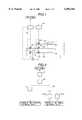
- FIG. 1is a diagrammatic view of a gas-turbine combustor in a preferred embodiment according to the present invention
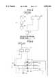
- FIG. 2is a block diagram of a fuel distribution ratio setting device employed in the present invention
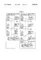
- FIG. 3is diagrams showing the variations of set values set by a premix fuel ratio calculator and a fuel flow distributor for premix burners employed in the present invention with load;
- FIG. 4is a block diagram of a pressure ratio setting device employed in the present invention.
- FIG. 5is diagrams showing set values set by the pressure ratio setting device
- FIG. 6is a diagrammatic view of a gas-turbine combustor in another embodiment according to the present invention.
- FIG. 7is diagrams showing set values set by a pressure ratio setting device
- FIG. 8is graphs showing fuel characteristics when fuel supply is changed.
- FIG. 9is diagrams showing the opening of valves when load is disconnected.
- the gas-turbine combustor 1has a single diffusion burner and two premix burners.
- a fuel distribution ratio setting device 14provides a fuel flow control signal to control the respective openings of flow control valves 4-a, 4-b and 10 for flow control.
- a pressure ratio setting device 15provides a pressure control signal to control pressures in pipes by controlling pressure control valves 6 and 12.
- a pressure gauge 16is connected to the exit side of the premix pressure control valve 6.
- the gas-turbine combustor 1is provided with a single diffusion nozzle 8 and two premix nozzles 2-a and 2-b.
- Pipes 9, 11 and 13are connected to the diffusion nozzle 8, the flow control valve 10 and the pressure control valve 12 are interposed between the pipes 9 and 11 and between the pipes 11 and 13, respectively.
- Pipes 3-a, 3-b, 5 and 7are connected to the premix nozzles 2-a and 2-b as shown in FIG. 1.
- the flow control valves 4-a and 4-bare interposed between the 3-a and 5 and between the pipes 3-b and 5, respectively.
- the premix pressure control valve 6is interposed between the pipes 5 and 7.
- the pipe 7is a main premix fuel pipe for supplying the fuel through the pipes 3-a and 3-b to the premix nozzles 2-a and 2-b.
- the pressure control valve 12adjusts the pressure of the fuel of a supply pressure supplied thereto through the pipe 13 to a predetermined pressure, the fuel of the predetermined pressure flows through the pipe 11 to the flow control valve 10, the flow control valve 10 adjusts the flow of the fuel to a predetermined flow, and the fuel is supplied at the predetermined flow to the diffusion nozzle 8 for combustion in the gas-turbine combustor 1.
- the opening of the pressure control valve 12is regulated on the basis of a pressure control signal provided by the pressure ratio setting device 15, and the opening of the flow control valve 10 is regulated on the basis of a flow control signal provided by the fuel distribution ratio setting device 14.
- the premix pressure control valve 6adjusts the pressure of the fuel of a supply pressure supplied thereto through the pipe 7 to a predetermined pressure.
- the pressure gauge 16 connected to the pipe 5measures the pressure of the fuel adjusted by the premix pressure control valve 6 and gives a control signal representing the measured pressure of the fuel to the pressure ratio setting device 15.
- the fuel of the predetermined pressureis distributed by the pipe 5 to the flow control valves 4-a and 4-b.
- the flow control valves 4-a and 4-bcontrol the flow of the fuel so that the fuel is supplied at predetermined flows through the pipes 3-a and 3-b to the premix nozzles 2-a and 2-b for combustion in the gas-turbine combustor 1.
- the respective openings of the flow control valves 4-a and 4-bare regulated on the basis of a flow control signal provided by the fuel distribution ratio setting device 14.
- a load signal representing load on the plantis given to the fuel distribution ratio setting device 14 and the pressure ratio setting device 15, and opening signals corresponding to operating condition are given to the premix pressure control valve 6 and the flow control valves 4-a, 4-b and 10.
- the fuel distribution ratio setting device 14 and the pressure ratio setting device 15will be described in detail with reference to FIGS. 2, 3, 4 and 5.
- a fuel signal converter 17converts a load signal representing load on the plant into a fuel flow signal and gives the fuel flow signal to a premix fuel ratio calculator 18.
- Predetermined premix-diffusion fuel distribution ratios respectively corresponding to loadsare set in the premix fuel ratio calculator 18.
- the premix fuel ratio calculator 18provides fuel flow signals specifying flows of the fuel to be supplied to the premix burners and the diffusion burner.
- One of the output signals of the premix fuel ratio calculator 18is given to a valve opening signal generator 19, and then the valve opening signal generator 19 provides a valve opening signal specifying an opening for the flow control valve 10 corresponding to the fuel flow signal.
- the other output signal of the premix fuel ratio calculator 18is given to a premix fuel flow distributor 20 for the premix burners. Distribution ratios for the premix burners respectively corresponding to loads are stored in the premix fuel flow distributor 20.
- the premix fuel flow distributor 20gives opening signals to opening signal generators 21-a and 21-b.
- the opening signal generators 21-a and 21-bgive opening signals to the fuel control valves 4-a and 4-b.
- FIG. 3is diagrams typically showing set values corresponding to load and set by the premix fuel ratio calculator 18 and the premix fuel flow distributor 20 shown in FIG. 2.
- the upper graphshows the variation of the set premix-diffusion fuel distribution ratio with openings for the flow control valves 4-a and 4-b shown in FIG. 1 with load.
- the gas-turbine combustor 1operates in a diffusion combustion mode in which the fuel is supplied only through the diffusion flow control valve 10 for only diffusion combustion.
- the gas-turbine combustor 1operates in a diffusion-dominant combustion mode in which the fuel is supplied through the diffusion flow control valve 10 and the premix flow control valve 4-a, the premix flow control valve 4-a is kept at a fixed opening and the opening of the diffusion flow control valve 10 is increased with the increase of load.
- the premix flow control valve 4-bis opened at a predetermined opening and the gas-turbine combustor 1 starts operating in a premix-dominant combustion mode in which both the premix burners operate for combustion.
- the diffusion flow control valve 10may be closed and the gas-turbine combustor 1 may operate in a premix combustion mode in which only premix combustion is performed for the further reduction of Nox emission.
- a load signal representing load on the plantis given to a supply pressure setting device 22 and a fuel supply mode deciding device 23.
- the supply pressure setting device 22provides a signal representing a set supply pressure corresponding to the load signal.
- a subtractor 25gives a differential signal representing the difference between the pressure measured by the pressure gage 16 and the set supply pressure to a PI controller 28.
- the PI controller 26provides signals representing variations to be made in the openings of the pressure control valves 6 and 12 to reduce the differential signal provided by the subtractor 25 to zero.
- the fuel supply mode deciding device 23decides whether fuel supply to the premix burners is to be started or whether fuel supply to the premix burners is to be stopped, and whether the premix burners are to be operated on the basis of a set value corresponding to the load signal.
- the fuel supply mode deciding device 23examines the load signal and decides whether or not the load represented by the load signal coincides with a fuel supply mode changing load, i.e., a load which requires the increase or decrease of operating burning systems to which the fuel is supplied.
- a fuel supply mode changing loadi.e., a load which requires the increase or decrease of operating burning systems to which the fuel is supplied.
- Optimum set valuesare stored in an opening change rate setting device 24 for a state in which the premix burners are operated partly in addition to diffusion combustion, and a state in which where the fuel is supplied to all the premix burners as shown in FIG. 3.
- the subtractor 25which receives the output signal of the pressure gage 16 processes the output signal of the supply pressure setting device 22, and gives a signal representing the results of operation to the PI controller 26.
- the output of the PI controller 26is transferred through a switch 27 to the pressure control valves 6 and 12 shown in FIG. 1.
- the output of the opening change rate setting device 24is transferred through the switch 27 to the pressure control valves 6 and 12.
- FIG. 5shows set values set by the pressure ratio setting device 15. If the fuel supply mode deciding device 23 decides supplying the fuel to part of the premix burners, the premix flow control valves 4-a and 4-b, the diffusion flow control valve 10 and the premix pressure control valve 6 are regulated by a fuel supply mode change signal provided by the fuel supply mode deciding device 23 in modes expressed by diagrams on the left-hand side in FIG. 5.
- the fuel supply mode deciding device 23Upon the start of opening of the premix flow control valve 4-a, the fuel supply mode deciding device 23 provides a signal to operate the switch 27 so as to select the opening change rate setting device 24 and a signal is given to the premix pressure control valve 6 so that the set value provided by the opening change rate setting device 24 is held forcibly constant until the opening of the premix flow control valve 4-a stops varying. Consequently, the opening of the premix pressure control valve 6 is kept constant during the period.
- the switch 27After the opening of the premix flow control valve 4-a has increased to a desired opening, the switch 27 is returned to a position for starting the supply pressure control operation of the PI controller 26.
- the supply pressure control operation of the PI controller 26causes the supply pressure controlled by the premix supply pressure control valve 6 to pulsate.
- the fuel supply mode deciding device 23decides that all the premix burners are to be operated (the number of the operating premix burners is to be increased, if any premix burner has been in operation) and provides a fuel supply mode change signal to that effect, the premix flow control valves 4-a and 4-b, the diffusion flow control valve 10 and the premix pressure control valve 6 are controlled in modes expressed by diagrams on the right-hand side in FIG. 5.
- the opening of the premix flow control valve 4-a connected to the premix burner 2-a which has been in operationis kept constant, the switch 27 is operated by the output signal of the fuel Supply mode deciding device 23 so as to connect the opening change rate setting device 24 to the premix pressure control valve 6 to give a predetermined set opening change rate to the premix pressure control valve 6 until the opening of the premix flow control valve 4-b changes from zero to a desired opening or to a substantially full opening. Therefore, during this period, the premix pressure control valve 6 operates at the predetermined opening change rate.
- the opening change rate setting device 24sets an opening change rate so that pressure variation in the pipe 5 caused by the fuel flowing through the premix flow control valve 4-b is absorbed. For example, the predetermined rate opens the pressure control valve in expectation of pressure drop in the fuel pipe due to the sudden increase of the flow rate of the fuel. Thus pressure variation is suppressed.
- the opening of the premix flow control valve 6can be changed to a desired opening at a fixed change rate when the desired opening of the premix flow control valve 6 for a combustion mode in which the diffusion nozzle 8 and the premix nozzle 2-a are in operation for combustion is changed to a desired opening of the premix flow control valve 6 to a combustion mode in which the diffusion nozzle 8 and the premix nozzles 2-a and 2-b are in operation for combustion.
- the switch 27is operated so as to start supply pressure control operation using the output of the PI controller 26 upon the increase of the opening of the premix flow control valve 4-b to a desired opening or to a fixed opening.
- the supply pressure control operation of the PI controller 26causes the supply pressure controlled by the premix supply pressure control valve 6 to pulsate.
- a supply pressure control operation similar to the foregoing supply pressure control operationis carried out when the fixed opening of the premix flow control valve 4-b is decreased to zero.
- the opening of the premix pressure control valve 6is decreased at a predetermined change rate during the closing operation of the flow control valve.
- the opening of the premix flow control valve 4-a connected to the premix burner 2-a operating for combustion at a predetermined fuel-air ratiois held constant, and the closed premix flow control valve 4-b is opened (or the fully open premix flow control valve 4-b is closed), the opening of the premix pressure control valve 6 is changed at the predetermined change rate so that the variation of the pressure in the fuel pipe 5 attributable to the variation of the flow of the fuel is suppressed or absorbed. Therefore, the pressure variation in the fuel pipe 5 can be suppressed in a short time and hence the time necessary for making the gas-turbine combustor reach a rated operating state (or an inoperative state) can be shortened and the range of variation of the output of the plant can be narrowed.
- the unstable burning operation of the premix burners during the fuel supply mode changing operationcan be avoided and the emission of the unburned fuel can be reduced by holding the fuel-air ratio for the operating premix burners.
- FIG. 6shows a gas-turbine combustor in another embodiment according to the present invention, which is provided with a single pressure control valve 12 instead of the pressure control valves 6 and 12 employed in the gas-turbine combustor of FIG. 1.
- pressures in the fuel pipesare measured by pressure sensors, and the pressure control valve 12 is controlled in a feedback control mode on the basis of the output signals of the pressure sensors.
- a valve 10is opened to supply the fuel to the diffusion nozzle 8 for diffusion combustion.
- a diffusion burnerprovided with the diffusion nozzle 8 is used as a pilot burner.
- a valve 4-ais opened to supply the fuel to the premix nozzle 2-a.
- a valve 4-bis opened to supply the fuel also to the premix nozzle 2-b.
- valve 10is closed to stop fuel supply to the diffusion nozzle 8 upon the increase of the load to a predetermined level and the gas-turbine combustor is operated in a premix combustion mode which is effective in reducing the emission of Nox.
- valves 10, 4-a and 4-bare operated in modes expressed by diagrams on the left-hand side of FIG. 7.
- the respective operating modes of the valves 10 and 4-aare similar to those illustrated in FIG. 5.
- the opening of the pressure control valve 12is increased at a predetermined opening rate while the respective openings of the valves 10 and 4-a are varied.
- the valves 10, 4-a and 4-bare operated in modes expressed by diagrams on the right-hand side of FIG. 7, which is substantially similar to those illustrated in FIG. 5, when the number of the premix burners is increased.
- the rate of changing the opening of the pressure control valve 12 when the valve 4-a is opened to change the operating mode of the gas-turbine combustor from a diffusion combustion mode to a diffusion-and-premix combustion modemay be greater than that of the pressure control valve 12 when the valve 4-b is opened to change the operating mode of the gas-turbine combustor from the diffusion-and-premix combustion mode to a premix combustion mode.
- the flow control valve 4-bis closed, the opening of the flow control valve 4-a is held constant, and the flow control valve 10 is opened.
- the flow control valve 4-bis closed, the flow of the fuel in fuel pipes 5 and 7 varies and the pressures of the fuel in the pipes 5 and 7 rise.
- the flow of the fuel in a pipe 11varies and the pressure of the fuel in the pipe 11 drops when the flow control valve 10 is opened.
- the pressure variation which occurs when changing the fuel supply modecan be suppressed in a short time by controlling the pressure of the fuel supplied to the combustion nozzles by the pressure control valve 12 placed in the main fuel pipe 13, whereby stable combustion can be achieved.
- the pressure variationcan be further quickly suppressed by closing the pressure control valve 12 at the foregoing predetermined change rate.
- Increase of the volume of the internal space of the fuel pipe between the pressure control valve 12 and the flow control valve 10 and the increase of the opening of the flow control valve 10 for supplying the fuel to the diffusion burnerare effective in making the pressure in the fuel pipes 5 and 7 and the pressure in the fuel pipe 11 cancel out each other smoothly.
- the fuel pipes for supplying the fuel to the premix burners and the fuel pipe for supplying the fuel to the diffusion burnerare connected to the single pressure control valve 12 to make the fuel pressure variation in the premix combustion system and the fuel pressure variation in the diffusion combustion system cancel out each other when changing the fuel supply mode, so that the variation of the flow in the fuel pipes can be suppressed in a short time, the total flow of the fuel between the pressure control valve 12 and the flow control valves 4-a, 4-b and 10 varies in a narrow range and hence the fuel can be stably supplied.
- FIG. 9A mode of operation of the gas-turbine combustor when the load is disconnected from the gas-turbine combustor will be described with reference to FIG. 9 showing the operations of the valves when a load disconnection signal is given and the operating mode of the gas-turbine combustor changes from a diffusion-and-premix combustion mode to a diffusion combustion mode in which fuel supply to the premix nozzles is stopped.
- the operations of the valves of the gas-turbine combustor shown in FIG. 1 provided with the two pressure control valves respectively for the premix nozzles and the diffusion nozzleare expressed by diagrams on the left-hand side
- the operations of the valves of the gas-turbine combustor shown in FIG. 6 provided with the single pressure control valve for both the premix nozzles and the diffusion nozzleare expressed by diagrams on the right-hand side.
- the effect of the stop of premix combustion in response to the disconnection of the load on the flow of the fuel to the diffusion nozzleis greater in the gas-turbine combustor shown in FIG. 6 in which the main fuel pipe is branched into the fuel pipe for supplying the fuel to the premix nozzles and the fuel pipe for supplying the fuel to the diffusion nozzle at a position below the pressure control valve 12 than in the gas-turbine combustor shown in FIG. 1.
- the flow control valves 4-a and 4-b connected to the premix nozzlesare closed and, at the same time, the flow control valve 10 connected to the diffusion nozzle is opened when a load disconnection signal is provided, and the opening of the pressure control valve 12 for controlling the pressure of the fuel to be supplied to the diffusion nozzle is increased at a predetermined change rate.
- the flow control valves 4-a and 4-b connected to the premix nozzlesare closed, the flow control valve 10 connected to the diffusion nozzle is opened when a load disconnection signal is provided, and the opening of the pressure control valve 12 is decreased at a predetermined change rate.
- the variation of the pressure in the fuel supply pipescan be suppressed in a short time even in a state where the load is disconnected and the operating mode of the gas-turbine combustor is changed suddenly from the diffusion-and-premix combustion mode to the diffusion combustion mode.
Landscapes
- Engineering & Computer Science (AREA)
- Chemical & Material Sciences (AREA)
- Combustion & Propulsion (AREA)
- Mechanical Engineering (AREA)
- General Engineering & Computer Science (AREA)
- Feeding And Controlling Fuel (AREA)
Abstract
Description
Claims (3)
Priority Applications (1)
| Application Number | Priority Date | Filing Date | Title |
|---|---|---|---|
| US09/512,350US6145297A (en) | 1996-11-27 | 2000-02-24 | Gas-turbine combustor with load-responsive premix burners |
Applications Claiming Priority (2)
| Application Number | Priority Date | Filing Date | Title |
|---|---|---|---|
| JP33161496 | 1996-11-27 | ||
| JP8-331614 | 1996-11-27 |
Related Child Applications (1)
| Application Number | Title | Priority Date | Filing Date |
|---|---|---|---|
| US09/512,350DivisionUS6145297A (en) | 1996-11-27 | 2000-02-24 | Gas-turbine combustor with load-responsive premix burners |
Publications (1)
| Publication Number | Publication Date |
|---|---|
| US6092362Atrue US6092362A (en) | 2000-07-25 |
Family
ID=18245633
Family Applications (2)
| Application Number | Title | Priority Date | Filing Date |
|---|---|---|---|
| US08/979,322Expired - LifetimeUS6092362A (en) | 1996-11-27 | 1997-11-26 | Gas-turbine combustor with load-responsive premix burners |
| US09/512,350Expired - LifetimeUS6145297A (en) | 1996-11-27 | 2000-02-24 | Gas-turbine combustor with load-responsive premix burners |
Family Applications After (1)
| Application Number | Title | Priority Date | Filing Date |
|---|---|---|---|
| US09/512,350Expired - LifetimeUS6145297A (en) | 1996-11-27 | 2000-02-24 | Gas-turbine combustor with load-responsive premix burners |
Country Status (1)
| Country | Link |
|---|---|
| US (2) | US6092362A (en) |
Cited By (38)
| Publication number | Priority date | Publication date | Assignee | Title |
|---|---|---|---|---|
| US6282885B1 (en)* | 1999-02-26 | 2001-09-04 | Honda Giken Kogyo Kabushiki Kaisha | Gas turbine engine |
| US6385975B1 (en)* | 1998-05-08 | 2002-05-14 | Mitsubishi Heavy Industries, Ltd. | Gas turbine fuel system comprising fuel oil distribution control system, fuel oil purge system, purging air supply system and fuel nozzle wash system |
| US20030037536A1 (en)* | 2001-08-24 | 2003-02-27 | Mitsubishi Heavy Industries, Ltd. | Gas turbine combustor apparatus |
| WO2004038199A1 (en)* | 2002-10-22 | 2004-05-06 | Kawasaki Jukogyo Kabushiki Kaisha | Method and system for controlling gas turbine engine |
| US20040107701A1 (en)* | 2002-05-31 | 2004-06-10 | Yoshiaki Miyake | System and method for controlling combustion in gas turbine with annular combustor |
| US6761033B2 (en)* | 2002-07-18 | 2004-07-13 | Hitachi, Ltd. | Gas turbine combustor with fuel-air pre-mixer and pre-mixing method for low NOx combustion |
| US20040172951A1 (en)* | 2001-07-19 | 2004-09-09 | Frank Hannemann | Method for operating a burner of a gas turbine and a power plant |
| US6871503B1 (en)* | 1999-10-20 | 2005-03-29 | Hitachi, Ltd. | Gas turbine combustor with fuel-air pre-mixer and pre-mixing method for low nox combustion |
| US20050268617A1 (en)* | 2004-06-04 | 2005-12-08 | Amond Thomas Charles Iii | Methods and apparatus for low emission gas turbine energy generation |
| US20060260319A1 (en)* | 2005-05-20 | 2006-11-23 | General Electric Company | NOx ADJUSTMENT METHOD FOR GAS TURBINE COMBUSTORS |
| US20070186557A1 (en)* | 2006-02-15 | 2007-08-16 | General Electric Company | Pressure control method and system to reduce gas turbine fuel supply pressure requirements |
| US20090025396A1 (en)* | 2007-07-24 | 2009-01-29 | General Electric Company | Parallel turbine fuel control valves |
| US20090214989A1 (en)* | 2008-02-25 | 2009-08-27 | Larry William Swanson | Method and apparatus for staged combustion of air and fuel |
| ITCO20090054A1 (en)* | 2009-11-27 | 2011-05-28 | Nuovo Pignone Spa | METHOD OF MODE CONTROL BASED ON EXHAUST TEMPERATURE FOR GAS TURBINE AND GAS TURBINE |
| ITCO20090055A1 (en)* | 2009-11-27 | 2011-05-28 | Nuovo Pignone Spa | METHOD OF MODE CONTROL BASED ON EXHAUST TEMPERATURE FOR GAS TURBINE AND GAS TURBINE |
| US20110146807A1 (en)* | 2008-06-09 | 2011-06-23 | Carsten Bassmann | Method for rinsing a fuel system of a gas turbine and associated fuel system |
| US8028512B2 (en) | 2007-11-28 | 2011-10-04 | Solar Turbines Inc. | Active combustion control for a turbine engine |
| US8437941B2 (en) | 2009-05-08 | 2013-05-07 | Gas Turbine Efficiency Sweden Ab | Automated tuning of gas turbine combustion systems |
| EP2568218A3 (en)* | 2011-09-09 | 2013-06-05 | General Electric Company | Fuel gas pressure control system and method for reducing gas turbine fuel supply pressure requirements |
| US20140294559A1 (en)* | 2013-03-28 | 2014-10-02 | Solar Turbines Incorporated | Multiple mode gas turbine engine gas fuel system with integrated control |
| US8904803B2 (en) | 2009-11-27 | 2014-12-09 | Nuovo Pignone S.P.A. | Exhaust temperature based threshold for control method and turbine |
| US9267443B2 (en) | 2009-05-08 | 2016-02-23 | Gas Turbine Efficiency Sweden Ab | Automated tuning of gas turbine combustion systems |
| US20160069476A1 (en)* | 2014-03-12 | 2016-03-10 | Ge Energy Products France Snc | Control process for operation of valves of a gas supply device of the gas turbine |
| US9354618B2 (en) | 2009-05-08 | 2016-05-31 | Gas Turbine Efficiency Sweden Ab | Automated tuning of multiple fuel gas turbine combustion systems |
| US20160161123A1 (en)* | 2014-12-05 | 2016-06-09 | General Electric Company | Fuel supply system for a gas turbine engine |
| US9671797B2 (en) | 2009-05-08 | 2017-06-06 | Gas Turbine Efficiency Sweden Ab | Optimization of gas turbine combustion systems low load performance on simple cycle and heat recovery steam generator applications |
| US20170248083A1 (en)* | 2016-02-26 | 2017-08-31 | 8 Rivers Capital, Llc | Systems and methods for controlling a power plant |
| WO2017196356A1 (en)* | 2016-05-12 | 2017-11-16 | Siemens Aktiengesellschaft | A method of selective combustor control for reduced emissions |
| US20180142580A1 (en)* | 2011-03-25 | 2018-05-24 | Kabushiki Kaisha Toshiba | Heat recovery steam generator and power plant |
| US20180209352A1 (en)* | 2014-08-06 | 2018-07-26 | Mitsubishi Hitachi Power Systems, Ltd. | Flow ratio calculation device, control device provided with same, gas turbine plant provided with said control device, flow ratio calculation method, and method for controlling fuel system |
| US20210341149A1 (en)* | 2020-05-01 | 2021-11-04 | Mitsubishi Power, Ltd. | Gas Turbine Combustor |
| US11313562B2 (en)* | 2018-02-13 | 2022-04-26 | Siemens Energy Global GmbH & Co. KG | Method for operating a burner arrangement of a gas turbine |
| US11473509B2 (en) | 2014-11-12 | 2022-10-18 | 8 Rivers Capital, Llc | Control systems and methods suitable for use with power production systems and methods |
| US11555457B2 (en)* | 2016-03-08 | 2023-01-17 | Mitsubishi Heavy Industries, Ltd. | Fuel control device, combustor, gas turbine, fuel control method, and program |
| US11686258B2 (en) | 2014-11-12 | 2023-06-27 | 8 Rivers Capital, Llc | Control systems and methods suitable for use with power production systems and methods |
| US12110822B2 (en) | 2019-10-22 | 2024-10-08 | 8 Rivers Capital, Llc | Control schemes for thermal management of power production systems and methods |
| US20250043731A1 (en)* | 2021-11-10 | 2025-02-06 | Nuovo Pignone Tecnologie - S.R.L. | Power plant for controlling the renewable energy use in an lng train |
| US12331690B2 (en) | 2021-11-10 | 2025-06-17 | Nuovo Pignone Tecnologie—S.R.L. | Method of controlling the renewable energy use in an LNG train |
Families Citing this family (11)
| Publication number | Priority date | Publication date | Assignee | Title |
|---|---|---|---|---|
| JP3783442B2 (en)* | 1999-01-08 | 2006-06-07 | 株式会社日立製作所 | Control method of gas turbine |
| DE50213936D1 (en)* | 2001-06-22 | 2009-12-03 | Alstom Technology Ltd | Method for starting up a gas turbine plant |
| JP2003113721A (en)* | 2001-10-03 | 2003-04-18 | Mitsubishi Heavy Ind Ltd | Method and apparatus for adjusting fuel ratio in gas turbine combustor |
| US6772583B2 (en) | 2002-09-11 | 2004-08-10 | Siemens Westinghouse Power Corporation | Can combustor for a gas turbine engine |
| US7377114B1 (en)* | 2004-06-02 | 2008-05-27 | Kevin P Pearce | Turbine engine pulsed fuel injection utilizing stagger injector operation |
| JP4015656B2 (en)* | 2004-11-17 | 2007-11-28 | 三菱重工業株式会社 | Gas turbine combustor |
| EP2075440B1 (en)* | 2007-12-31 | 2012-05-30 | Ansaldo Energia S.P.A. | Method and device for controlling a gas-turbine plant |
| JP4979615B2 (en)* | 2008-03-05 | 2012-07-18 | 株式会社日立製作所 | Combustor and fuel supply method for combustor |
| CH700991A1 (en)* | 2009-05-13 | 2010-11-15 | Alstom Technology Ltd | Method for operating a gas turbine plant with a compressor station for gaseous fuel. |
| US20130167549A1 (en)* | 2011-12-29 | 2013-07-04 | Chad M. Holcomb | Compressor guide vane and pilot control for gas turbine engine |
| KR102068305B1 (en)* | 2018-03-19 | 2020-01-20 | 두산중공업 주식회사 | Combustor, and gas turbine including the same |
Citations (4)
| Publication number | Priority date | Publication date | Assignee | Title |
|---|---|---|---|---|
| US4716719A (en)* | 1985-04-17 | 1988-01-05 | Hitachi, Ltd. | Method of and apparatus for controlling fuel of gas turbine |
| US5272637A (en)* | 1990-03-19 | 1993-12-21 | Hitachi, Ltd. | Method and apparatus for controlling the supply of fuel to a gas turbine during load rejection |
| JPH06257748A (en)* | 1992-12-30 | 1994-09-16 | General Electric Co <Ge> | Gas turbine, combustion section of gas turbine and adjusting method of fuel to separate combustion chamber of gas turbine |
| US5806299A (en)* | 1996-02-16 | 1998-09-15 | Man Gutehoffnungshutte Aktiengesellschaft | Process and apparatus for quickly switching over from premix combustion to diffusion combustion in a gas turbine |
- 1997
- 1997-11-26USUS08/979,322patent/US6092362A/ennot_activeExpired - Lifetime
- 2000
- 2000-02-24USUS09/512,350patent/US6145297A/ennot_activeExpired - Lifetime
Patent Citations (4)
| Publication number | Priority date | Publication date | Assignee | Title |
|---|---|---|---|---|
| US4716719A (en)* | 1985-04-17 | 1988-01-05 | Hitachi, Ltd. | Method of and apparatus for controlling fuel of gas turbine |
| US5272637A (en)* | 1990-03-19 | 1993-12-21 | Hitachi, Ltd. | Method and apparatus for controlling the supply of fuel to a gas turbine during load rejection |
| JPH06257748A (en)* | 1992-12-30 | 1994-09-16 | General Electric Co <Ge> | Gas turbine, combustion section of gas turbine and adjusting method of fuel to separate combustion chamber of gas turbine |
| US5806299A (en)* | 1996-02-16 | 1998-09-15 | Man Gutehoffnungshutte Aktiengesellschaft | Process and apparatus for quickly switching over from premix combustion to diffusion combustion in a gas turbine |
Cited By (74)
| Publication number | Priority date | Publication date | Assignee | Title |
|---|---|---|---|---|
| US6385975B1 (en)* | 1998-05-08 | 2002-05-14 | Mitsubishi Heavy Industries, Ltd. | Gas turbine fuel system comprising fuel oil distribution control system, fuel oil purge system, purging air supply system and fuel nozzle wash system |
| US6282885B1 (en)* | 1999-02-26 | 2001-09-04 | Honda Giken Kogyo Kabushiki Kaisha | Gas turbine engine |
| US6871503B1 (en)* | 1999-10-20 | 2005-03-29 | Hitachi, Ltd. | Gas turbine combustor with fuel-air pre-mixer and pre-mixing method for low nox combustion |
| US20040172951A1 (en)* | 2001-07-19 | 2004-09-09 | Frank Hannemann | Method for operating a burner of a gas turbine and a power plant |
| US7726133B2 (en)* | 2001-07-19 | 2010-06-01 | Siemens Aktiengesellschaft | Method for operating a burner of a gas turbine and a power plant |
| US6880325B2 (en)* | 2001-08-24 | 2005-04-19 | Mitsubishi Heavy Industries, Ltd. | Gas turbine combustor apparatus |
| US20030037536A1 (en)* | 2001-08-24 | 2003-02-27 | Mitsubishi Heavy Industries, Ltd. | Gas turbine combustor apparatus |
| US20040107701A1 (en)* | 2002-05-31 | 2004-06-10 | Yoshiaki Miyake | System and method for controlling combustion in gas turbine with annular combustor |
| US7024862B2 (en)* | 2002-05-31 | 2006-04-11 | Mitsubishi Heavy Industries, Ltd. | System and method for controlling combustion in gas turbine with annular combustor |
| US6761033B2 (en)* | 2002-07-18 | 2004-07-13 | Hitachi, Ltd. | Gas turbine combustor with fuel-air pre-mixer and pre-mixing method for low NOx combustion |
| US20040255594A1 (en)* | 2002-10-22 | 2004-12-23 | Makoto Baino | Method and system for controlling gas turbine engine |
| WO2004038199A1 (en)* | 2002-10-22 | 2004-05-06 | Kawasaki Jukogyo Kabushiki Kaisha | Method and system for controlling gas turbine engine |
| US7051533B2 (en) | 2002-10-22 | 2006-05-30 | Kawasaki Jukogyo Kabushiki Kaisha | Method and system for controlling gas turbine engine |
| US20050268617A1 (en)* | 2004-06-04 | 2005-12-08 | Amond Thomas Charles Iii | Methods and apparatus for low emission gas turbine energy generation |
| US7284378B2 (en)* | 2004-06-04 | 2007-10-23 | General Electric Company | Methods and apparatus for low emission gas turbine energy generation |
| US7441398B2 (en)* | 2005-05-20 | 2008-10-28 | General Electric Company | NOx adjustment system for gas turbine combustors |
| US20090007566A1 (en)* | 2005-05-20 | 2009-01-08 | General Electric Company | NOx ADJUSTMENT METHOD FOR GAS TURBINE COMBUSTORS |
| US20060260319A1 (en)* | 2005-05-20 | 2006-11-23 | General Electric Company | NOx ADJUSTMENT METHOD FOR GAS TURBINE COMBUSTORS |
| US8033117B2 (en) | 2005-05-20 | 2011-10-11 | General Electric Company | NOx adjustment method for gas turbine combustors |
| US20070186557A1 (en)* | 2006-02-15 | 2007-08-16 | General Electric Company | Pressure control method and system to reduce gas turbine fuel supply pressure requirements |
| US7549293B2 (en) | 2006-02-15 | 2009-06-23 | General Electric Company | Pressure control method to reduce gas turbine fuel supply pressure requirements |
| US8286414B2 (en) | 2006-02-15 | 2012-10-16 | General Electric Company | Pressure control method and system to reduce gas turbine fuel supply pressure requirements |
| US20090241510A1 (en)* | 2006-02-15 | 2009-10-01 | General Electric Company | Pressure control method and system to reduce gas turbine fuel supply pressure requirements |
| US20090025396A1 (en)* | 2007-07-24 | 2009-01-29 | General Electric Company | Parallel turbine fuel control valves |
| US20110154802A1 (en)* | 2007-07-24 | 2011-06-30 | Rahul Mohan Joshi | Parallel turbine fuel control valves |
| US8028512B2 (en) | 2007-11-28 | 2011-10-04 | Solar Turbines Inc. | Active combustion control for a turbine engine |
| US20090214989A1 (en)* | 2008-02-25 | 2009-08-27 | Larry William Swanson | Method and apparatus for staged combustion of air and fuel |
| US7775791B2 (en)* | 2008-02-25 | 2010-08-17 | General Electric Company | Method and apparatus for staged combustion of air and fuel |
| US9175606B2 (en)* | 2008-06-09 | 2015-11-03 | Siemens Aktiengesellschaft | Method for rinsing a fuel system of a gas turbine and associated fuel system |
| US20110146807A1 (en)* | 2008-06-09 | 2011-06-23 | Carsten Bassmann | Method for rinsing a fuel system of a gas turbine and associated fuel system |
| US10260428B2 (en) | 2009-05-08 | 2019-04-16 | Gas Turbine Efficiency Sweden Ab | Automated tuning of gas turbine combustion systems |
| US11199818B2 (en) | 2009-05-08 | 2021-12-14 | Gas Turbine Efficiency Sweden Ab | Automated tuning of multiple fuel gas turbine combustion systems |
| US10509372B2 (en) | 2009-05-08 | 2019-12-17 | Gas Turbine Efficiency Sweden Ab | Automated tuning of multiple fuel gas turbine combustion systems |
| US8437941B2 (en) | 2009-05-08 | 2013-05-07 | Gas Turbine Efficiency Sweden Ab | Automated tuning of gas turbine combustion systems |
| US9671797B2 (en) | 2009-05-08 | 2017-06-06 | Gas Turbine Efficiency Sweden Ab | Optimization of gas turbine combustion systems low load performance on simple cycle and heat recovery steam generator applications |
| US9354618B2 (en) | 2009-05-08 | 2016-05-31 | Gas Turbine Efficiency Sweden Ab | Automated tuning of multiple fuel gas turbine combustion systems |
| US11028783B2 (en) | 2009-05-08 | 2021-06-08 | Gas Turbine Efficiency Sweden Ab | Automated tuning of gas turbine combustion systems |
| US9328670B2 (en) | 2009-05-08 | 2016-05-03 | Gas Turbine Efficiency Sweden Ab | Automated tuning of gas turbine combustion systems |
| US9267443B2 (en) | 2009-05-08 | 2016-02-23 | Gas Turbine Efficiency Sweden Ab | Automated tuning of gas turbine combustion systems |
| US8820089B2 (en) | 2009-11-27 | 2014-09-02 | Nuovo Pignone S.P.A. | Exhaust temperature based mode control method for gas turbine and gas turbine |
| ITCO20090054A1 (en)* | 2009-11-27 | 2011-05-28 | Nuovo Pignone Spa | METHOD OF MODE CONTROL BASED ON EXHAUST TEMPERATURE FOR GAS TURBINE AND GAS TURBINE |
| US8904803B2 (en) | 2009-11-27 | 2014-12-09 | Nuovo Pignone S.P.A. | Exhaust temperature based threshold for control method and turbine |
| ITCO20090055A1 (en)* | 2009-11-27 | 2011-05-28 | Nuovo Pignone Spa | METHOD OF MODE CONTROL BASED ON EXHAUST TEMPERATURE FOR GAS TURBINE AND GAS TURBINE |
| WO2011064343A1 (en)* | 2009-11-27 | 2011-06-03 | Nuovo Pignone S.P.A. | Exhaust temperature based mode control method for gas turbine and gas turbine |
| US8713946B2 (en) | 2009-11-27 | 2014-05-06 | Nuovo Pignone S.P.A. | Exhaust temperature based threshold for control method and turbine |
| AU2010323059B2 (en)* | 2009-11-27 | 2016-07-21 | Nuovo Pignone Tecnologie - S.R.L. | Exhaust temperature based mode control method for gas turbine and gas turbine |
| RU2540210C2 (en)* | 2009-11-27 | 2015-02-10 | Нуово Пиньоне С.п.А. | Gas turbine operation control method based on temperature of exhaust gas and gas turbine |
| WO2011064142A1 (en)* | 2009-11-27 | 2011-06-03 | Nuovo Pignone S.P.A. | Exhaust temperature based mode control method for gas turbine and gas turbine |
| US20180142580A1 (en)* | 2011-03-25 | 2018-05-24 | Kabushiki Kaisha Toshiba | Heat recovery steam generator and power plant |
| US10344627B2 (en)* | 2011-03-25 | 2019-07-09 | Kabushiki Kaisha Toshiba | Heat recovery steam generator and power plant |
| EP2568218A3 (en)* | 2011-09-09 | 2013-06-05 | General Electric Company | Fuel gas pressure control system and method for reducing gas turbine fuel supply pressure requirements |
| US8915059B2 (en) | 2011-09-09 | 2014-12-23 | General Electric Company | Fuel gas pressure control system and method for reducing gas turbine fuel supply pressure requirements |
| US20140294559A1 (en)* | 2013-03-28 | 2014-10-02 | Solar Turbines Incorporated | Multiple mode gas turbine engine gas fuel system with integrated control |
| US20160069476A1 (en)* | 2014-03-12 | 2016-03-10 | Ge Energy Products France Snc | Control process for operation of valves of a gas supply device of the gas turbine |
| US9677686B2 (en)* | 2014-03-12 | 2017-06-13 | General Electric Company | Control process for operation of valves of a gas supply device of the gas turbine |
| US20180209352A1 (en)* | 2014-08-06 | 2018-07-26 | Mitsubishi Hitachi Power Systems, Ltd. | Flow ratio calculation device, control device provided with same, gas turbine plant provided with said control device, flow ratio calculation method, and method for controlling fuel system |
| US10612472B2 (en)* | 2014-08-06 | 2020-04-07 | Mitsubishi Hitachi Power Systems, Ltd. | Flow ratio calculation device, control device provided with same, gas turbine plant provided with said control device, flow ratio calculation method, and method for controlling fuel system |
| US12012904B2 (en) | 2014-11-12 | 2024-06-18 | 8 Rivers Capital, Llc | Control systems and methods suitable for use with power production systems and methods |
| US11686258B2 (en) | 2014-11-12 | 2023-06-27 | 8 Rivers Capital, Llc | Control systems and methods suitable for use with power production systems and methods |
| US11473509B2 (en) | 2014-11-12 | 2022-10-18 | 8 Rivers Capital, Llc | Control systems and methods suitable for use with power production systems and methods |
| US20160161123A1 (en)* | 2014-12-05 | 2016-06-09 | General Electric Company | Fuel supply system for a gas turbine engine |
| US10012387B2 (en)* | 2014-12-05 | 2018-07-03 | General Electric Company | Fuel supply system for a gas turbine engine |
| US20170248083A1 (en)* | 2016-02-26 | 2017-08-31 | 8 Rivers Capital, Llc | Systems and methods for controlling a power plant |
| US10731571B2 (en)* | 2016-02-26 | 2020-08-04 | 8 Rivers Capital, Llc | Systems and methods for controlling a power plant |
| US11466627B2 (en) | 2016-02-26 | 2022-10-11 | 8 Rivers Capital, Llc | Systems and methods for controlling a power plant |
| US11555457B2 (en)* | 2016-03-08 | 2023-01-17 | Mitsubishi Heavy Industries, Ltd. | Fuel control device, combustor, gas turbine, fuel control method, and program |
| US11067279B2 (en) | 2016-05-12 | 2021-07-20 | Siemens Energy Global GmbH & Co. KG | Method of selective combustor control for reduced emissions |
| WO2017196356A1 (en)* | 2016-05-12 | 2017-11-16 | Siemens Aktiengesellschaft | A method of selective combustor control for reduced emissions |
| US11313562B2 (en)* | 2018-02-13 | 2022-04-26 | Siemens Energy Global GmbH & Co. KG | Method for operating a burner arrangement of a gas turbine |
| US12110822B2 (en) | 2019-10-22 | 2024-10-08 | 8 Rivers Capital, Llc | Control schemes for thermal management of power production systems and methods |
| US11493206B2 (en)* | 2020-05-01 | 2022-11-08 | Mitsubishi Heavy Industries, Ltd. | Gas turbine combustor having main fuel valves independently adjustable |
| US20210341149A1 (en)* | 2020-05-01 | 2021-11-04 | Mitsubishi Power, Ltd. | Gas Turbine Combustor |
| US20250043731A1 (en)* | 2021-11-10 | 2025-02-06 | Nuovo Pignone Tecnologie - S.R.L. | Power plant for controlling the renewable energy use in an lng train |
| US12331690B2 (en) | 2021-11-10 | 2025-06-17 | Nuovo Pignone Tecnologie—S.R.L. | Method of controlling the renewable energy use in an LNG train |
Also Published As
| Publication number | Publication date |
|---|---|
| US6145297A (en) | 2000-11-14 |
Similar Documents
| Publication | Publication Date | Title |
|---|---|---|
| US6092362A (en) | Gas-turbine combustor with load-responsive premix burners | |
| US6558154B2 (en) | Burner system with staged fuel injection and method for its operation | |
| US7654092B2 (en) | System for modulating fuel supply to individual fuel nozzles in a can-annular gas turbine | |
| US6370863B2 (en) | Method of operating a gas-turbine chamber with gaseous fuel | |
| EP0962704B1 (en) | Apparatus for use with a gas fueled combustor | |
| US4766721A (en) | Combustor for gas turbine | |
| US5016443A (en) | Fuel-air premixing device for a gas turbine | |
| JPH05149149A (en) | Gas turbine combustor | |
| US20030106320A1 (en) | Gas turbine pilot burner and method | |
| US5281129A (en) | Combustion apparatus and control method therefor | |
| JP4143401B2 (en) | Fuel supply method and apparatus for premix burner | |
| JP3716586B2 (en) | Gas turbine combustor | |
| JP3188140B2 (en) | Multi-nozzle combustor for gas turbine and control method therefor | |
| KR19990063325A (en) | Devices for use with liquid fuel combustors | |
| JPH0461169B2 (en) | ||
| JPH0411729B2 (en) | ||
| JPH0115775B2 (en) | ||
| JP3472424B2 (en) | Gas turbine and method of operating gas turbine | |
| JPH0461168B2 (en) | ||
| JPH0610426B2 (en) | Gas turbine control device | |
| JP3703615B2 (en) | Gas turbine equipment | |
| JPH07260139A (en) | Burning vibration preventing apparatus | |
| JP3110558B2 (en) | Combustor combustion method | |
| JPS61138836A (en) | Gas turbine controller | |
| JPH04124522A (en) | Fuel feeding method for combustion device, fuel feeding system, and diffusion fuel nozzle |
Legal Events
| Date | Code | Title | Description |
|---|---|---|---|
| AS | Assignment | Owner name:HITACHI, LTD., JAPAN Free format text:ASSIGNMENT OF ASSIGNORS INTEREST;ASSIGNORS:NAGAFUCHI, NAOYUKI;KIMURA, YOTARO;ITO, KAZUYUKI;REEL/FRAME:010641/0464 Effective date:19971118 | |
| STCF | Information on status: patent grant | Free format text:PATENTED CASE | |
| FEPP | Fee payment procedure | Free format text:PAYOR NUMBER ASSIGNED (ORIGINAL EVENT CODE: ASPN); ENTITY STATUS OF PATENT OWNER: LARGE ENTITY | |
| FPAY | Fee payment | Year of fee payment:4 | |
| FPAY | Fee payment | Year of fee payment:8 | |
| FEPP | Fee payment procedure | Free format text:PAYER NUMBER DE-ASSIGNED (ORIGINAL EVENT CODE: RMPN); ENTITY STATUS OF PATENT OWNER: LARGE ENTITY | |
| FEPP | Fee payment procedure | Free format text:PAYOR NUMBER ASSIGNED (ORIGINAL EVENT CODE: ASPN); ENTITY STATUS OF PATENT OWNER: LARGE ENTITY | |
| FPAY | Fee payment | Year of fee payment:12 | |
| AS | Assignment | Owner name:MITSUBISHI HITACHI POWER SYSTEMS, LTD., JAPAN Free format text:CHANGE OF NAME;ASSIGNOR:HITACHI, LTD.;REEL/FRAME:033003/0648 Effective date:20140201 | |
| AS | Assignment | Owner name:MITSUBISHI HITACHI POWER SYSTEMS, LTD., JAPAN Free format text:CONFIRMATORY ASSIGNMENT;ASSIGNOR:HITACHI, LTD.;REEL/FRAME:033917/0209 Effective date:20140917 |