US6091967A - Scalable radio platform - Google Patents
Scalable radio platformDownload PDFInfo
- Publication number
- US6091967A US6091967AUS08/846,394US84639497AUS6091967AUS 6091967 AUS6091967 AUS 6091967AUS 84639497 AUS84639497 AUS 84639497AUS 6091967 AUS6091967 AUS 6091967A
- Authority
- US
- United States
- Prior art keywords
- signals
- parameter data
- system parameter
- component
- control element
- Prior art date
- Legal status (The legal status is an assumption and is not a legal conclusion. Google has not performed a legal analysis and makes no representation as to the accuracy of the status listed.)
- Expired - Lifetime
Links
Images


Classifications
- H—ELECTRICITY
- H04—ELECTRIC COMMUNICATION TECHNIQUE
- H04W—WIRELESS COMMUNICATION NETWORKS
- H04W92/00—Interfaces specially adapted for wireless communication networks
- H04W92/02—Inter-networking arrangements
- H—ELECTRICITY
- H04—ELECTRIC COMMUNICATION TECHNIQUE
- H04W—WIRELESS COMMUNICATION NETWORKS
- H04W88/00—Devices specially adapted for wireless communication networks, e.g. terminals, base stations or access point devices
- H04W88/08—Access point devices
- H—ELECTRICITY
- H04—ELECTRIC COMMUNICATION TECHNIQUE
- H04W—WIRELESS COMMUNICATION NETWORKS
- H04W88/00—Devices specially adapted for wireless communication networks, e.g. terminals, base stations or access point devices
- H04W88/08—Access point devices
- H04W88/10—Access point devices adapted for operation in multiple networks, e.g. multi-mode access points
- H—ELECTRICITY
- H04—ELECTRIC COMMUNICATION TECHNIQUE
- H04W—WIRELESS COMMUNICATION NETWORKS
- H04W92/00—Interfaces specially adapted for wireless communication networks
- H04W92/16—Interfaces between hierarchically similar devices
- H04W92/18—Interfaces between hierarchically similar devices between terminal devices
Definitions
- This inventionrelates to wireless communication systems and more particularly to a scalable radio platform that enables users of different wireless systems to communicate with each other.
- Wireless communicationshas experienced a tremendous growth in the past few years. As a result, there is an ever increasing demand by users to use these systems to convey not only voice signals, but also data signals and video signals.
- Several wireless communication systemshave emerged as accepted standards in various parts of the world. Some of the major wireless communication systems include the Advanced Mobile Phone Service (AMPS), Personal Communication Services (PCS), GSM (Group Speciale Mobile), the High Performance Radio Local Area Network (HIPERLAN) and its U.S. equivalent, Unlicensed National Information Structure (U-NII) systems. Some of these systems are analog systems while others are digital. That is, some of these systems use analog modulation techniques while others use digital modulation techniques. Also, these systems allow their subscribers to access their equipment in different manners. Some systems use Frequency Division Multiple Access (FDMA) schemes while others use Time Division Multiple Access (TDMA) schemes, Code Division Multiple Access (CDMA) or F/TDMA (combination of FDMA and TDMA) schemes.
- FDMAFrequency Division Multiple Access
- TDMATime Division Multiple Access
- system parameterse.g., bandwidth, frequency of operation, transfer rate
- system providers at their great expenseoften have to change or modify their system equipment to comply with these changing parameters.
- factorssuch as sudden increases in subscriber usage or changing radio signal propagation conditions may effect the performance of the system.
- system providersto alter some of their system parameters (e.g., increase or reduce bandwidth, decrease transfer rate to reduce bit error rate) on an as needed basis in order to adapt their system to changing system conditions allowing them to operate their system more efficiently.
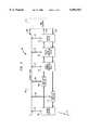
- FIG. 1depicts a typical wireless system.
- FIG. 1shows a system level diagram of a typical digital cellular wireless system that uses a CDMA scheme.
- Message Switching Center (MSC) 6communicates with the Public Switched Telephone Network (PSTN) 2 over bidirectional line 4.
- PSTNPublic Switched Telephone Network
- MSC 6communicates with Cell Sites (CS) 12 located in each cell 14 via communication links 8.
- Each cell 14is depicted as a hexagon which is a symbolic representation of the geographic terrain or physical area that is being served by a cell site. The cell can be represented with the use of other geometric shapes.
- Within each cell 14are a plurality of mobile users 10 who communicate with each other, with users of other cells and with users within PSTN 2.
- Cell sites 12communicate with mobile users 10 within each cell via wireless communication links 16.
- the Cell sites 12typically contain (among other devices) a communication controller (not shown) that transmits, processes and/or receives information signals from either the users of the system, the MSC or other system equipment.
- User information signalsare typically in the form of analog or digital voice signals, video signals or digital data signals.
- the system information signalsare similarly represented and are used by the system equipment to monitor, control and operate the overall system.
- Wireless communication links 16actually comprise two channels (not shown).
- One channelcommonly referred to as the system channel, is used to convey system information signals between mobile users 10 and cell sites 14.
- the other channelcommonly referred to as the traffic channel, is used to convey user information signals between the mobile users 10 and cell sites 14.
- the systemis designed so that only mobile users who have subscribed to the system and who are located within one of the cells can use the system.
- the present inventionprovides a scalable radio platform for a wireless communication system.
- the communication systemhas host equipment that use information signals to communicate with other host equipment.
- the scalable radio platformwhich is interfaced to one of the host equipment, uses system parameter data received from the host equipment to enable the host equipment to communicate with different communication systems. Also, the scalable radio platform enables the communication system to modify its performance to adapt to changing system conditions.
- the scalable radio platformcomprises a control element interfaced to the host equipment where the control element is configured to exchange system parameter data with the host equipment.
- the control elementgenerates control signals based on the system parameter data.
- the scalable radio platformfurther comprises at least one component that is interfaced to the host equipment and configured to communicate with the host equipment with information signals.
- the componentis also interfaced to the control element and configured to receive the control signals and process the information signals in accordance with the received control signals.
- FIG. 1is a prior art system level diagram of a typical cellular communication system
- FIG. 2is a block diagram of the present invention interfaced to host equipment of a wireless communication system
- FIG. 3is a detailed block diagram of the present invention.
- FIG. 4is a block diagram of the present invention interfaced to a user communication device of a wireless communication system.
- FIG. 5is a block diagram of the present invention interfaced to a cell site communication controller of a digital cellular wireless communication system.
- FIG. 2shows Scalable Radio Platform (SRP) 200 interfaced to host equipment 208.
- Host equipment 208is typically part of a wireless communication system that has host equipment which communicate with other host equipment with information signals. That is, various host equipment transmit and or receive information signals to and from other host equipment.
- the information signalscomprise user information signals and system information signals.
- Host equipment 208can be either system equipment (e.g., a cell site communication controller, or other network equipment), or user equipment (e.g., a user communication device, a human operated cellular phone, a portable computer).
- a user communication devicecan be, for example, a facsimile machine, a modem or any other communication device that is used by a user to transmit and/or receive information signals in a wireless communication system.
- Information signals which have been processed by SRP 200are transferred to host equipment 208 over interface 204.
- Information signals to be processed by SRP 200are received by way of interface 206.
- host equipment 208has a set of system parameter data which dictate how the information signals are to be processed by SRP 200 and also define how SRP 200 in conjunction with host equipment 208 is to communicate with other host equipment or other communication devices that have the same system parameters as host equipment 208.
- the data associated with the system parametersare exchanged between SRP 200 and host equipment 208 over interface 202.
- This datawhich shall henceforth be referred to as system parameter data, can be stored by SRP 200.
- Host equipment 208may, for example, have the following set of parameters that are used in communicating with another device: 1. System operating frequency (f) 2. System bandwidth (b) 3. System Transfer Rate (t) and 4. System protocol (p). This list of parameters is merely illustrative and is by no means comprehensive. Additional parameters or a different set of parameters can be used to define how a communication system processes its information signals and thus communicate with other communication devices.
- SRP 200has the capability to store system parameter values and settings and, based on such data, possibly modify the way it processes the information signals. SRP 200 also has the capability to store the received system parameter data and change the stored system parameter data based on the received system parameter data. Users having an SRP interfaced to their equipment, such as a cellular phone, have the capability to use a number of different wireless communication systems and are no longer constrained by their particular physical location. Similarly, service providers of wireless systems with an SRP interfaced to their system equipment can thus serve users with incompatible system parameters and are able to modify the performance of their system to adapt to changing system conditions. Although FIG. 2 shows SRP 200 interfaced to only one host equipment, it will be understood by one of ordinary skill in the art to which this invention belongs that SRP 200 can be interfaced to more than one host equipment.
- FIG. 3shows a more detailed block diagram of the Scalable Radio Platform interfaced to host equipment 314.
- Control element 301 of SRP 300exchanges system parameter data with host equipment 314 via interface 316.
- Control element 301generates control signals based on the system parameter data received from host equipment 314 and transmits these control signals over interfaces 330, 328, 326, 324, 322 and 332 to various components of SRP 300.
- Information signals to and from host equipment 314are conveyed over interfaces 318 and 320 respectively.
- Information signals in the form of radio signalsare received and transmitted to and from wireless link 334.
- Wireless link 334depending on the particular communication system, may be used to convey both user information signals and system information signals as is typical in wireless communication systems.
- the interfacesare conduits through which control signals, status signals, system parameter data and information signals are conveyed. These interfaces can be electrical wire connections, optical fiber connections, optoelectronic devices or any other well known electronic interface circuitry.
- control signalsare based on the system parameter data.
- the control signalscan be electrical, electronic, electromechanical, optical or any other type of signal typically used to activate in some manner electrical circuitry or devices.
- the componentsprocess the information signals in accordance with the control signals received from control element 301.
- the components of SRP 300comprise Antenna Subsystem 312, Receiver amplifier 308, Transmitter amplifier 310, Radio Frequency Processing device 306, Digital Signal Processing device 304 and Protocol device 302.
- the above list of componentsrepresents devices that are typically used in communication systems to process information signals. Other components which also process information signals in communication systems can also be made part of SRP 300.
- the system parameter datais stored in control element 301. Also, the components send status signals to control element 301 over their respective interfaces in response to received control signals.
- Control element 301may want to determine the current state of a particular component. Control element 301 may, for example, transmit control signals to a component to cause said component to transmit status signals over its interface to inform control element 301 of the current state of that component.
- Each componentcan be implemented with programmable circuitry that is well known in the art of programmable electronics allowing it to modify the manner in which it processes information signals in response to control signals received from control element 301.
- Each componentcan also be implemented with standard circuitry whose electrical response and performance can be modified directly by the control signals. These types of modifiable circuits are well known in the art of electronic and electrical circuit design.
- Control element 301can be implemented as a microprocessor based circuit with memory circuits (not shown) that are used to store received system parameter data.
- Part of the control element's memory circuitcan have firmware that analyze the incoming system parameter data and generate the proper control signals as a function of the latest system parameter data.
- the firmwaremay be able to also detect circumstances in which several system parameters have to be modified in response to a change in one or more system parameter.
- control element 301may have stored a plurality of system parameter sets that are acceptable standard values for various well known systems or networks.
- the control elementmay, for example, provide assistance to host equipment 314 in establishing the system parameter data to be used by SRP 300.
- control elementmay receive system parameter data that changes the current protocol setting. However, the new protocol setting may not be operable at the current transfer rate and bandwidth.
- the control element's firmwarewould detect this situation by comparing the incoming system parameter data with the stored system parameter data and change the transfer rate and bandwidth to proper settings and values to achieve the performance mandated by the received system parameter data.
- control element 301may contain several algorithms that determine not only whether a received set of system parameter data is compatible to known systems but also whether such a set of system parameter data is even achievable based on basic communication principles.
- Control element 301can, on its own or upon the request of host equipment 314, transmit its current set of stored system parameter data to host equipment 314 by way of interface 316.
- the design of control element 301is not limited to the particular implementation described above. Other realizations of control element 301, which perform in the same manner, can be created.
- antenna subsystem 312can be implemented as an array of antennae each one of which can be selected by control element 301 based on received system parameter data. That is, control element 301 transmits control signals over interface 330 to antenna subsystem 312 to activate the appropriate antenna from the set of antennae.
- the selected antennareceives information signals in the form of radio signals transmitted over wireless link 334 which are then transferred to receiver amplifier 308.
- the selected antennaalso receives information signals from transmitter amplifier 310 and converts the information to radio signals that are transmitted over wireless link 334.
- Receiver amplifier 308 and transmitter amplifier 310are set at their proper operating frequency and amplification values due to control signals received from control element 301 via interfaces 326 and 328 respectively. It is well known in the art of electronic circuit design to implement amplifiers that can change their amplification value and frequency of operation in response to received control signals. Receiver amplifier 308 receives information signals from antenna subsystem 312 and applies the proper amplification and frequency response to these signals. The output of amplifier 308 is transferred to radio frequency processing device 306. Transmitter amplifier 310 receives information signals from radio frequency processing device 306. Transmitter amplifier 310 applies the proper amplification and frequency response to these information signals and transfers them to antenna subsystem 312.
- Control element 301transmits control signals related to frequency of operation to radio frequency processing device 306 via interface 324.
- Radio frequency processing device 306receives modulated baseband signals from digital signal processing device 304.
- Radio frequency processing device 306may, for example, be implemented as a mixer-amplifier which has a local oscillator at one of its inputs; the local oscillator being variable or programmable such that it can oscillate at any one of a plurality of frequencies in response to a control signal.
- Radio frequency processing device 306implemented as a variable mixer amplifier or similar circuitry would be able to convert baseband signals to various radio frequency signals.
- the baseband signalsare shifted up in frequency and are located within a certain bandwidth defined by the system bandwidth parameter.
- radio frequency processing device 306receives high frequency signals from receiver amplifier 308. These high frequency signals are downshifted to baseband signals and are then transferred to digital signal processing device 304.
- Digital signal processing device 304receives control signals associated with bandwidth and transfer rate from control element 301 over interface 322. Digital signal processing device 304 modulates baseband signals received from protocol device 302. The modulation scheme used by this device ensures that the baseband signals are properly limited by the bandwidth and transfer rate set by the system. Digital signal processing device 304 also receives modulated baseband signals from radio frequency processing device 306. These signals are demodulated and then transferred to protocol device 302. Digital signal processing device 304 is designed so that the control signals received from control element 301 causes digital signal processing device 304 to modify the responses of its modulator and demodulator circuits (not shown).
- Protocol device 302receives information signals from host equipment 314 via interface 320.
- Protocol device 302packages and formats the information signals in accordance with the system protocol.
- a wireless digital cellular systemsuch as the one shown in FIG. 1 may be operated to comply with the well known IS-95A communication protocol which uses a CDMA scheme to enable its users to have access to the system.
- Protocol device 302may be designed to implement other multiple access schemes such as TDMA, FDMA or F/TDMA.
- the information signalsare converted to baseband signals by protocol device 302 and transferred to digital signal processing device 304 for modulation.
- demodulated baseband signals from digital signal processing device 304are transferred to protocol device 302 which processes the signals as per the protocol being used and transfers such signals to host equipment 314 via interface 318.
- Protocol device 302may be implemented as a programmable protocol controller which can implement different protocols at different transfer rates in response to control signals received from control element 301 over interface 332.
- Protocol device 302can be a microprocessor based circuit with supporting circuitry that can be programmed to accept incoming information signals at a particular transfer rate, package and format said information in accordance with the particular protocol being followed and transmit said information signals to digital signal processing device 304.
- SRP 300 in conjunction with host equipment 314would be able to communicate with another possibly different device that has the same system parameters as host equipment 314. Therefore, as discussed in detail above, information signals originating from host equipment 314 are transferred to SRP 300 via interface 320. The information signals are processed by the various components of SRP 300 and finally are transmitted by antenna subsystem component 312. Similarly, information signals received by antenna subsystem 312 are processed by the remaining components of SRP 300 and transferred to host equipment 314 via interface 318.
- the communication systemcan modify any or all of the system parameters.
- particular parametersmay be changed to adapt to local changes in radio conditions. For example, when radio conditions worsen such that excessive transmission errors occur, the bandwidth and or transfer rate may be reduced to achieve improved error performance. Under favorable radio conditions, however, the bandwidth or transfer rate may be increased to allow superior system performance.
- host equipment 314may communicate system information, related to system parameters, with the rest of the communication system. If one or more system parameter needs to be modified, host equipment 314 sends the proper system parameter data to control element 301 over interface 316.
- control element 301 of SRP 300first receives system parameter data from host equipment 314.
- Control element 301generates control signals based on the received system parameter data.
- Control element 301transmits these control signals to the components.
- the componentscommunicate with host equipment 314 or communicate another host equipment via antenna subsystem 312 with information signals and process these information signals in accordance with the system parameter data received from host equipment 3 14 or in accordance with the latest system parameter data stored in control element 301. That is, information signals can be received or transmitted by the components from host equipment 314; information signals can also be transmitted and received by the components to and from host equipment 314. It is, therefore in this manner that SRP 300 can modify the way it processes information signals based on the received system parameter data.
- FIG. 4shows SRP 402 interfaced with user communication device 400 of a cellular communication system.
- User communication device 400may be a portable personal computer, a cellular phone, an indoor wireless phone, a wireless phone for a wide area network, or other communication device that can be interfaced to an SRP.
- SRP 402can be integrated within the circuitry or system of user communication device 400. That is, SRP 400 need not be a separate physical device, but can be configured to become part of a user communication device. Thus, for example, SRP 400 can be integrated within the circuitry of a portable personal computer, a cellular phone, an indoor wireless phone etc.
- User information signals originating from user communication device 400is transferred to SRP 402 via interface 408.
- SRP 402transmits the user information signals over wireless communication channel 410 to a cell site (not shown). Conversely, user information signals received by SRP 402 over wireless communication channel 410 is processed by SRP 402 and then transferred to user communication device 400 via interface 406. SRP 402 and user communication device 400 exchange system information in a similar fashion.
- An example of a particular application of the system shown in FIG. 4follows.
- a user of the system shown in FIG. 4is using a portable personal computer equipped with a wireless modem and appropriate communications software within an indoor wireless communication system to retrieve data from a computer system, the user has more than one way to communicate with the communication system.
- the computer systemcan be a database, an operating system through which various application programs can be executed, a home page or web site that is part of the Internet or any other computer system configured to communicate with other computers.
- the indoor wireless systemnormally has an operating range within which a user of the system should be located in order to use this system. Suppose that the user is also situated within a cell of a cellular network providing wide area coverage.
- the computercan be programmed to have both sets of system parameters. When the user is within the boundaries of the indoor wireless system, the computer can also be programmed to provide the SRP with a set of system parameters (i.e., (f1, b1, t1, p1)) that is acceptable to the indoor wireless system and establish communication via the indoor wireless communication system.
- the programming of the computercan be done by the user, by the computer manufacturer or by the software manufacturer of a communication program being executed by the computer.
- the usercan for example, start retrieving information from the computer system via the indoor wireless communication system.
- the usercan continue to retrieve data from the computer system as long as the user is within the operating range of the indoor wireless communication system. It may be that the user has to leave the vicinity of the indoor wireless system but still needs to continue to retrieve information from the computer system. In such a circumstance, the user may, for example, terminate temporarily the retrieval of information from the computer system while still within the operating range of the indoor wireless communication system.
- the userinstructs the computer to send to SRP 402 a new set of system parameters containing new system parameter data (f2, b2, t2, p2).
- the SRPcan then establish communication with the cellular network and contact the now remote computer system via the cellular network.
- the set of system parameters for the cellular networkwas stored in the host equipment (portable personal computer) prior to establishing communication with the network. The user was then able to choose that network by simply causing its host equipment to transfer the new set of system parameter data to its SRP and then establish communication with that network.
- the host equipmentcan detect the presence of different wireless networks from data received by the SRP. In order to establish communication with a particular available wireless network, the user can use its host equipment to detect the existence of one or all of the available wireless networks.
- the usercan instruct its host equipment to listen for radio signals of a certain frequency or to perform a search of a band of the frequency spectrum known to be allocated to wireless networks.
- cell sites or base stations of wireless networkshave radio beacons that transmit signals announcing the presence of a wireless network in a certain geographical area.
- the beacon signalstypically contain system information about that particular network. This is a technique that is well known and widely used in various wireless communication systems.
- networks capable of serving users equipped with SRP based radio devicescan, for example, transmit their beacon signals on a well known frequency channel.
- the networkscan use the same methods of modulation and communication protocols for their beacon signals or comply with a prearranged protocol and modulation scheme specifically designed for their area of coverage.
- the particular method of modulationcan be a common method typically used by many wireless networks.
- the particular protocol usedcan be a basic protocol that can be easily implemented by many systems.
- the user communication device or host equipmentcan then, in conjunction with its SRP, conform to the system parameters or negotiate with the network regarding system parameter values and settings. If a user decides to use the services of a particular network, the user instructs its communication device to transfer the proper parameters of that network to its SRP and then engage in communication with the network.
- This particular techniqueis for illustrative purposes only and should not be construed as the only method that can be used to change system parameters. Other procedures may be followed when a user is changing from one wireless communication system to another. It should be noted that the decision to change system parameters may be made by the user or automatically done by the host equipment. The SRP then simply receives the system parameter data originating from the user or host equipment and its components modify the manner in which they process the information signals based on the latest system parameter data.
- Scalable Radio Platform (SRP) 504is interfaced to cell site communication controller 502 of a communication system.
- Cell site communication controller 502 and SRP 504are located within cell 518 which is part of a digital cellular wireless communication system similar to that shown in FIG. 1.
- SRP 504can be integrated within the circuitry and system of communication controller 502.
- SRP 504allows the communication system to modify or change its system parameters so that the system can serve mobile users 510 which have parameters that are different from the parameters of the system and also enables the system to adapt to changes in radio conditions.
- Cell site communication controller 502communicates with an MSC (not shown) over communication link 500 and communicates with a plurality of mobile users 510 over wireless communication link 506. For the sake of clarity, only one mobile user 510 is shown. Wireless communication link 506 may be used as a system channel and a traffic channel. User information signals originating from mobile user 510 are transmitted over wireless link 506 to SRP 504. SRP 504 processes these information signals in accordance with the system parameters and transfers them to cell site communication controller 502 over interface 514. Depending on the destination of the received user information signals, cell site communication controller 502 may transmit the user information signals to the MSC over communication link 500 or transmit (by way of SRP 504) the user information signals over wireless link 506 to another mobile user within cell 518.
- user information signals destined for mobile user 510 and originating from the MSCare received over communication link 500 by cell site communication controller 502.
- the user information signalsare then transferred via interface 516 to SRP 504 which processes the information signals in accordance with the system parameters.
- SRP 504then transmits the user information signals to mobile user 510 over wireless link 506.
- SRP 504 and cell site communication controller 502exchange system information signals in a similar fashion except that the system information signals are conveyed over wireless link 506.
- Interface 512is used by SRP 504 and cell site communication controller 502 to exchange system parameter data.
- Cell site communication controller 502can instruct SRP 504 to send its current system parameter data to cell site communication controller 502 over interface 512.
- Cell site communication controller 502may then transmit new system parameter data to SRP 504 ensuring that the information signals are processed by SRP 504 in accordance with the new system parameter data.
Landscapes
- Engineering & Computer Science (AREA)
- Computer Networks & Wireless Communication (AREA)
- Signal Processing (AREA)
- Mobile Radio Communication Systems (AREA)
- Transceivers (AREA)
Abstract
Description
Claims (17)
Priority Applications (5)
| Application Number | Priority Date | Filing Date | Title |
|---|---|---|---|
| US08/846,394US6091967A (en) | 1997-04-30 | 1997-04-30 | Scalable radio platform |
| CA002232324ACA2232324C (en) | 1997-04-30 | 1998-03-17 | Scalable radio platform |
| EP98303035AEP0876072A3 (en) | 1997-04-30 | 1998-04-21 | Variable radio interface |
| KR1019980015440AKR19980081848A (en) | 1997-04-30 | 1998-04-30 | Large capacity radio platform |
| JP10119820AJPH118890A (en) | 1997-04-30 | 1998-04-30 | Radio platform having compatibility |
Applications Claiming Priority (1)
| Application Number | Priority Date | Filing Date | Title |
|---|---|---|---|
| US08/846,394US6091967A (en) | 1997-04-30 | 1997-04-30 | Scalable radio platform |
Publications (1)
| Publication Number | Publication Date |
|---|---|
| US6091967Atrue US6091967A (en) | 2000-07-18 |
Family
ID=25297805
Family Applications (1)
| Application Number | Title | Priority Date | Filing Date |
|---|---|---|---|
| US08/846,394Expired - LifetimeUS6091967A (en) | 1997-04-30 | 1997-04-30 | Scalable radio platform |
Country Status (5)
| Country | Link |
|---|---|
| US (1) | US6091967A (en) |
| EP (1) | EP0876072A3 (en) |
| JP (1) | JPH118890A (en) |
| KR (1) | KR19980081848A (en) |
| CA (1) | CA2232324C (en) |
Cited By (32)
| Publication number | Priority date | Publication date | Assignee | Title |
|---|---|---|---|---|
| US20020075869A1 (en)* | 2000-12-18 | 2002-06-20 | Shah Tushar Ramanlal | Integration of network, data link, and physical layer to adapt network traffic |
| US6424818B1 (en)* | 1997-06-24 | 2002-07-23 | Ntt Mobile Communications Network, Inc. | Communication system using relayed radio channels |
| US20020103668A1 (en)* | 2001-01-31 | 2002-08-01 | Ecklund Terry Robert | Configuring architecture for mobile access to at least one business resource |
| US20020164113A1 (en)* | 2001-03-05 | 2002-11-07 | The Microoptical Corporation | Micro-electromechanical optical switch assembly for optical data networks |
| US20020181428A1 (en)* | 2001-05-29 | 2002-12-05 | Kruys Jan P. | Self-organizing system for wireless access |
| US6690949B1 (en)* | 1999-09-30 | 2004-02-10 | Skyworks Solutions, Inc. | System and process for supporting multiple wireless standards with a single circuit architecture |
| US6697375B1 (en)* | 1999-08-04 | 2004-02-24 | Atheros Communications, Inc. | Method and apparatus for bandwidth and frequency management in the U-NII band |
| US6738637B1 (en)* | 1998-12-16 | 2004-05-18 | Lucent Technologies Inc. | Dynamic variation of class of service in a communication network based on network resources |
| US7076168B1 (en)* | 1998-02-12 | 2006-07-11 | Aquity, Llc | Method and apparatus for using multicarrier interferometry to enhance optical fiber communications |
| US20060223470A1 (en)* | 2005-03-31 | 2006-10-05 | Fujitsu Limited | Radio-frequency communication control system, radio-frequency communication control method and computer-readable storage medium |
| US20080130689A1 (en)* | 2000-12-18 | 2008-06-05 | Addepalli Sateesh Kumar | Dynamic mixing of tdm data with data packets |
| US20080166984A1 (en)* | 2007-01-09 | 2008-07-10 | Terrence John Shie | Multiband or multimode receiver with shared bias circuit |
| US20100103273A1 (en)* | 2008-10-28 | 2010-04-29 | Canon Kabushiki Kaisha | Communication apparatus, control method of communication apparatus, program, and system |
| US9485063B2 (en) | 2001-04-26 | 2016-11-01 | Genghiscomm Holdings, LLC | Pre-coding in multi-user MIMO |
| US9628231B2 (en) | 2002-05-14 | 2017-04-18 | Genghiscomm Holdings, LLC | Spreading and precoding in OFDM |
| US10142082B1 (en) | 2002-05-14 | 2018-11-27 | Genghiscomm Holdings, LLC | Pre-coding in OFDM |
| US10200227B2 (en) | 2002-05-14 | 2019-02-05 | Genghiscomm Holdings, LLC | Pre-coding in multi-user MIMO |
| US10305636B1 (en) | 2004-08-02 | 2019-05-28 | Genghiscomm Holdings, LLC | Cooperative MIMO |
| US10644916B1 (en) | 2002-05-14 | 2020-05-05 | Genghiscomm Holdings, LLC | Spreading and precoding in OFDM |
| US10797733B1 (en) | 2001-04-26 | 2020-10-06 | Genghiscomm Holdings, LLC | Distributed antenna systems |
| US10880145B2 (en) | 2019-01-25 | 2020-12-29 | Genghiscomm Holdings, LLC | Orthogonal multiple access and non-orthogonal multiple access |
| US10931338B2 (en) | 2001-04-26 | 2021-02-23 | Genghiscomm Holdings, LLC | Coordinated multipoint systems |
| US11018918B1 (en) | 2017-05-25 | 2021-05-25 | Genghiscomm Holdings, LLC | Peak-to-average-power reduction for OFDM multiple access |
| US11115160B2 (en) | 2019-05-26 | 2021-09-07 | Genghiscomm Holdings, LLC | Non-orthogonal multiple access |
| US11184037B1 (en) | 2004-08-02 | 2021-11-23 | Genghiscomm Holdings, LLC | Demodulating and decoding carrier interferometry signals |
| US11196603B2 (en) | 2017-06-30 | 2021-12-07 | Genghiscomm Holdings, LLC | Efficient synthesis and analysis of OFDM and MIMO-OFDM signals |
| US11343823B2 (en) | 2020-08-16 | 2022-05-24 | Tybalt, Llc | Orthogonal multiple access and non-orthogonal multiple access |
| US11381285B1 (en) | 2004-08-02 | 2022-07-05 | Genghiscomm Holdings, LLC | Transmit pre-coding |
| US11552737B1 (en) | 2004-08-02 | 2023-01-10 | Genghiscomm Holdings, LLC | Cooperative MIMO |
| US11917604B2 (en) | 2019-01-25 | 2024-02-27 | Tybalt, Llc | Orthogonal multiple access and non-orthogonal multiple access |
| US12206535B1 (en) | 2018-06-17 | 2025-01-21 | Tybalt, Llc | Artificial neural networks in wireless communication systems |
| US12224860B1 (en) | 2014-01-30 | 2025-02-11 | Genghiscomm Holdings, LLC | Linear coding in decentralized networks |
Families Citing this family (5)
| Publication number | Priority date | Publication date | Assignee | Title |
|---|---|---|---|---|
| US6041228A (en)* | 1997-10-27 | 2000-03-21 | Telefonaktiebolaget Lm Ericsson | Open `plug and play` O and M architecture for a radio base station |
| FI111317B (en)* | 1999-06-28 | 2003-06-30 | Domiras Oy | Centralized control of telecommunication parameters |
| JP3517219B2 (en) | 2000-08-28 | 2004-04-12 | 松下電器産業株式会社 | Communication terminal accommodation device and communication terminal accommodation method |
| SE0300555D0 (en) | 2003-02-24 | 2003-02-24 | Ericsson Telefon Ab L M | Improvements in or relating to push-to-talk services |
| US8578046B2 (en)* | 2005-10-20 | 2013-11-05 | Qualcomm Incorporated | System and method for adaptive media bundling for voice over internet protocol applications |
Citations (9)
| Publication number | Priority date | Publication date | Assignee | Title |
|---|---|---|---|---|
| US5297193A (en)* | 1990-05-30 | 1994-03-22 | Alcatel N.V. | Wireless telephone network centralized maintenance method |
| US5384845A (en)* | 1993-04-14 | 1995-01-24 | International Telecommunications Satellite Organization | Command modulation system having command generator unit for commanding a plurality of different types of controlled units |
| GB2282299A (en)* | 1993-08-27 | 1995-03-29 | Motorola Ltd | Frequency allocation in a cellular radio system |
| US5420912A (en)* | 1993-02-27 | 1995-05-30 | Alcatel N.V. | Telephone having portable voice control module for playing back speech or performing a hands-free telephone function |
| WO1995023485A1 (en)* | 1994-02-28 | 1995-08-31 | Voxson International Pty. Limited | Multi-mode communications system |
| DE19526730A1 (en)* | 1994-08-25 | 1996-02-29 | Motorola Inc | Adaptive handheld radio telephone |
| US5797102A (en)* | 1994-01-05 | 1998-08-18 | Nokia Mobile Phones Limited | Arrangement for adapting the signal level in mobile phones |
| US5809432A (en)* | 1994-12-30 | 1998-09-15 | Nec Corporation | Portable radio terminal having a removable radio system unit |
| US5926756A (en)* | 1996-08-26 | 1999-07-20 | Motorola, Inc. | Method and system for programming a cellular phone |
- 1997
- 1997-04-30USUS08/846,394patent/US6091967A/ennot_activeExpired - Lifetime
- 1998
- 1998-03-17CACA002232324Apatent/CA2232324C/ennot_activeExpired - Fee Related
- 1998-04-21EPEP98303035Apatent/EP0876072A3/ennot_activeWithdrawn
- 1998-04-30JPJP10119820Apatent/JPH118890A/enactivePending
- 1998-04-30KRKR1019980015440Apatent/KR19980081848A/ennot_activeWithdrawn
Patent Citations (9)
| Publication number | Priority date | Publication date | Assignee | Title |
|---|---|---|---|---|
| US5297193A (en)* | 1990-05-30 | 1994-03-22 | Alcatel N.V. | Wireless telephone network centralized maintenance method |
| US5420912A (en)* | 1993-02-27 | 1995-05-30 | Alcatel N.V. | Telephone having portable voice control module for playing back speech or performing a hands-free telephone function |
| US5384845A (en)* | 1993-04-14 | 1995-01-24 | International Telecommunications Satellite Organization | Command modulation system having command generator unit for commanding a plurality of different types of controlled units |
| GB2282299A (en)* | 1993-08-27 | 1995-03-29 | Motorola Ltd | Frequency allocation in a cellular radio system |
| US5797102A (en)* | 1994-01-05 | 1998-08-18 | Nokia Mobile Phones Limited | Arrangement for adapting the signal level in mobile phones |
| WO1995023485A1 (en)* | 1994-02-28 | 1995-08-31 | Voxson International Pty. Limited | Multi-mode communications system |
| DE19526730A1 (en)* | 1994-08-25 | 1996-02-29 | Motorola Inc | Adaptive handheld radio telephone |
| US5809432A (en)* | 1994-12-30 | 1998-09-15 | Nec Corporation | Portable radio terminal having a removable radio system unit |
| US5926756A (en)* | 1996-08-26 | 1999-07-20 | Motorola, Inc. | Method and system for programming a cellular phone |
Cited By (75)
| Publication number | Priority date | Publication date | Assignee | Title |
|---|---|---|---|---|
| US6424818B1 (en)* | 1997-06-24 | 2002-07-23 | Ntt Mobile Communications Network, Inc. | Communication system using relayed radio channels |
| US7076168B1 (en)* | 1998-02-12 | 2006-07-11 | Aquity, Llc | Method and apparatus for using multicarrier interferometry to enhance optical fiber communications |
| US6738637B1 (en)* | 1998-12-16 | 2004-05-18 | Lucent Technologies Inc. | Dynamic variation of class of service in a communication network based on network resources |
| US7505479B2 (en) | 1999-08-04 | 2009-03-17 | Atheros Communications, Inc. | Method and apparatus for bandwidth and frequency management in the U-NII band |
| US6697375B1 (en)* | 1999-08-04 | 2004-02-24 | Atheros Communications, Inc. | Method and apparatus for bandwidth and frequency management in the U-NII band |
| US6690949B1 (en)* | 1999-09-30 | 2004-02-10 | Skyworks Solutions, Inc. | System and process for supporting multiple wireless standards with a single circuit architecture |
| US8503457B2 (en) | 2000-12-18 | 2013-08-06 | Netlogic Microsystems, Inc. | Method of forming a digital or analog multiplexing data frame |
| US20020075869A1 (en)* | 2000-12-18 | 2002-06-20 | Shah Tushar Ramanlal | Integration of network, data link, and physical layer to adapt network traffic |
| US20080130689A1 (en)* | 2000-12-18 | 2008-06-05 | Addepalli Sateesh Kumar | Dynamic mixing of tdm data with data packets |
| US7039591B2 (en) | 2001-01-31 | 2006-05-02 | Accenture Llp | Configuring architecture for mobile access to at least one business resource |
| WO2002061535A3 (en)* | 2001-01-31 | 2003-11-06 | Accenture Llp | Configuring architecture for mobile access to at least one business resource |
| US20020103668A1 (en)* | 2001-01-31 | 2002-08-01 | Ecklund Terry Robert | Configuring architecture for mobile access to at least one business resource |
| US6701038B2 (en) | 2001-03-05 | 2004-03-02 | The Microoptical Corporation | Micro-electromechanical optical switch assembly for optical data networks |
| US20020164113A1 (en)* | 2001-03-05 | 2002-11-07 | The Microoptical Corporation | Micro-electromechanical optical switch assembly for optical data networks |
| US9485063B2 (en) | 2001-04-26 | 2016-11-01 | Genghiscomm Holdings, LLC | Pre-coding in multi-user MIMO |
| US11424792B2 (en) | 2001-04-26 | 2022-08-23 | Genghiscomm Holdings, LLC | Coordinated multipoint systems |
| US10797732B1 (en) | 2001-04-26 | 2020-10-06 | Genghiscomm Holdings, LLC | Distributed antenna systems |
| US10797733B1 (en) | 2001-04-26 | 2020-10-06 | Genghiscomm Holdings, LLC | Distributed antenna systems |
| US10931338B2 (en) | 2001-04-26 | 2021-02-23 | Genghiscomm Holdings, LLC | Coordinated multipoint systems |
| US20020181428A1 (en)* | 2001-05-29 | 2002-12-05 | Kruys Jan P. | Self-organizing system for wireless access |
| US7548520B2 (en) | 2001-05-29 | 2009-06-16 | Agere Systems Inc | Self-organizing system for wireless access |
| US9800448B1 (en) | 2002-05-14 | 2017-10-24 | Genghiscomm Holdings, LLC | Spreading and precoding in OFDM |
| US10200227B2 (en) | 2002-05-14 | 2019-02-05 | Genghiscomm Holdings, LLC | Pre-coding in multi-user MIMO |
| US9768842B2 (en) | 2002-05-14 | 2017-09-19 | Genghiscomm Holdings, LLC | Pre-coding in multi-user MIMO |
| US10840978B2 (en) | 2002-05-14 | 2020-11-17 | Genghiscomm Holdings, LLC | Cooperative wireless networks |
| US9967007B2 (en) | 2002-05-14 | 2018-05-08 | Genghiscomm Holdings, LLC | Cooperative wireless networks |
| US10009208B1 (en) | 2002-05-14 | 2018-06-26 | Genghiscomm Holdings, LLC | Spreading and precoding in OFDM |
| US10015034B1 (en) | 2002-05-14 | 2018-07-03 | Genghiscomm Holdings, LLC | Spreading and precoding in OFDM |
| US10038584B1 (en) | 2002-05-14 | 2018-07-31 | Genghiscomm Holdings, LLC | Spreading and precoding in OFDM |
| US10142082B1 (en) | 2002-05-14 | 2018-11-27 | Genghiscomm Holdings, LLC | Pre-coding in OFDM |
| US9628231B2 (en) | 2002-05-14 | 2017-04-18 | Genghiscomm Holdings, LLC | Spreading and precoding in OFDM |
| US10211892B2 (en) | 2002-05-14 | 2019-02-19 | Genghiscomm Holdings, LLC | Spread-OFDM receiver |
| US10230559B1 (en) | 2002-05-14 | 2019-03-12 | Genghiscomm Holdings, LLC | Spreading and precoding in OFDM |
| US10903970B1 (en) | 2002-05-14 | 2021-01-26 | Genghiscomm Holdings, LLC | Pre-coding in OFDM |
| US10389568B1 (en) | 2002-05-14 | 2019-08-20 | Genghiscomm Holdings, LLC | Single carrier frequency division multiple access baseband signal generation |
| US10574497B1 (en) | 2002-05-14 | 2020-02-25 | Genghiscomm Holdings, LLC | Spreading and precoding in OFDM |
| US10587369B1 (en) | 2002-05-14 | 2020-03-10 | Genghiscomm Holdings, LLC | Cooperative subspace multiplexing |
| US10644916B1 (en) | 2002-05-14 | 2020-05-05 | Genghiscomm Holdings, LLC | Spreading and precoding in OFDM |
| US10778492B1 (en) | 2002-05-14 | 2020-09-15 | Genghiscomm Holdings, LLC | Single carrier frequency division multiple access baseband signal generation |
| US11025468B1 (en) | 2002-05-14 | 2021-06-01 | Genghiscomm Holdings, LLC | Single carrier frequency division multiple access baseband signal generation |
| US11025312B2 (en) | 2002-05-14 | 2021-06-01 | Genghiscomm Holdings, LLC | Blind-adaptive decoding of radio signals |
| US11252005B1 (en) | 2004-08-02 | 2022-02-15 | Genghiscomm Holdings, LLC | Spreading and precoding in OFDM |
| US11381285B1 (en) | 2004-08-02 | 2022-07-05 | Genghiscomm Holdings, LLC | Transmit pre-coding |
| US10305636B1 (en) | 2004-08-02 | 2019-05-28 | Genghiscomm Holdings, LLC | Cooperative MIMO |
| US12095529B2 (en) | 2004-08-02 | 2024-09-17 | Genghiscomm Holdings, LLC | Spread-OFDM receiver |
| US11018917B1 (en) | 2004-08-02 | 2021-05-25 | Genghiscomm Holdings, LLC | Spreading and precoding in OFDM |
| US11804882B1 (en) | 2004-08-02 | 2023-10-31 | Genghiscomm Holdings, LLC | Single carrier frequency division multiple access baseband signal generation |
| US11784686B2 (en) | 2004-08-02 | 2023-10-10 | Genghiscomm Holdings, LLC | Carrier interferometry transmitter |
| US11671299B1 (en) | 2004-08-02 | 2023-06-06 | Genghiscomm Holdings, LLC | Wireless communications using flexible channel bandwidth |
| US11075786B1 (en) | 2004-08-02 | 2021-07-27 | Genghiscomm Holdings, LLC | Multicarrier sub-layer for direct sequence channel and multiple-access coding |
| US11646929B1 (en) | 2004-08-02 | 2023-05-09 | Genghiscomm Holdings, LLC | Spreading and precoding in OFDM |
| US11184037B1 (en) | 2004-08-02 | 2021-11-23 | Genghiscomm Holdings, LLC | Demodulating and decoding carrier interferometry signals |
| US11575555B2 (en) | 2004-08-02 | 2023-02-07 | Genghiscomm Holdings, LLC | Carrier interferometry transmitter |
| US11223508B1 (en) | 2004-08-02 | 2022-01-11 | Genghiscomm Holdings, LLC | Wireless communications using flexible channel bandwidth |
| US11552737B1 (en) | 2004-08-02 | 2023-01-10 | Genghiscomm Holdings, LLC | Cooperative MIMO |
| US11252006B1 (en) | 2004-08-02 | 2022-02-15 | Genghiscomm Holdings, LLC | Wireless communications using flexible channel bandwidth |
| US11431386B1 (en) | 2004-08-02 | 2022-08-30 | Genghiscomm Holdings, LLC | Transmit pre-coding |
| US20060223470A1 (en)* | 2005-03-31 | 2006-10-05 | Fujitsu Limited | Radio-frequency communication control system, radio-frequency communication control method and computer-readable storage medium |
| US7881676B2 (en)* | 2005-03-31 | 2011-02-01 | Fujitsu Limited | Radio-frequency communication control system, radio-frequency communication control method and computer-readable storage medium |
| US20080166984A1 (en)* | 2007-01-09 | 2008-07-10 | Terrence John Shie | Multiband or multimode receiver with shared bias circuit |
| US7729674B2 (en) | 2007-01-09 | 2010-06-01 | Skyworks Solutions, Inc. | Multiband or multimode receiver with shared bias circuit |
| US20100103273A1 (en)* | 2008-10-28 | 2010-04-29 | Canon Kabushiki Kaisha | Communication apparatus, control method of communication apparatus, program, and system |
| US12395268B1 (en) | 2014-01-30 | 2025-08-19 | Genghiscomm Holdings, LLC | Linear network coding in communication networks |
| US12224860B1 (en) | 2014-01-30 | 2025-02-11 | Genghiscomm Holdings, LLC | Linear coding in decentralized networks |
| US11018918B1 (en) | 2017-05-25 | 2021-05-25 | Genghiscomm Holdings, LLC | Peak-to-average-power reduction for OFDM multiple access |
| US11894965B2 (en) | 2017-05-25 | 2024-02-06 | Tybalt, Llc | Efficient synthesis and analysis of OFDM and MIMO-OFDM signals |
| US11700162B2 (en) | 2017-05-25 | 2023-07-11 | Tybalt, Llc | Peak-to-average-power reduction for OFDM multiple access |
| US11196603B2 (en) | 2017-06-30 | 2021-12-07 | Genghiscomm Holdings, LLC | Efficient synthesis and analysis of OFDM and MIMO-OFDM signals |
| US11570029B2 (en) | 2017-06-30 | 2023-01-31 | Tybalt Llc | Efficient synthesis and analysis of OFDM and MIMO-OFDM signals |
| US12206535B1 (en) | 2018-06-17 | 2025-01-21 | Tybalt, Llc | Artificial neural networks in wireless communication systems |
| US11917604B2 (en) | 2019-01-25 | 2024-02-27 | Tybalt, Llc | Orthogonal multiple access and non-orthogonal multiple access |
| US10880145B2 (en) | 2019-01-25 | 2020-12-29 | Genghiscomm Holdings, LLC | Orthogonal multiple access and non-orthogonal multiple access |
| US11791953B2 (en) | 2019-05-26 | 2023-10-17 | Tybalt, Llc | Non-orthogonal multiple access |
| US11115160B2 (en) | 2019-05-26 | 2021-09-07 | Genghiscomm Holdings, LLC | Non-orthogonal multiple access |
| US11343823B2 (en) | 2020-08-16 | 2022-05-24 | Tybalt, Llc | Orthogonal multiple access and non-orthogonal multiple access |
Also Published As
| Publication number | Publication date |
|---|---|
| CA2232324C (en) | 2001-10-09 |
| EP0876072A2 (en) | 1998-11-04 |
| EP0876072A3 (en) | 2000-03-08 |
| KR19980081848A (en) | 1998-11-25 |
| JPH118890A (en) | 1999-01-12 |
| CA2232324A1 (en) | 1998-10-30 |
Similar Documents
| Publication | Publication Date | Title |
|---|---|---|
| US6091967A (en) | Scalable radio platform | |
| US7013162B2 (en) | Dual mode unit for short range, high rate and long range, lower rate data communications | |
| US7024222B2 (en) | Dual mode unit for short range, high rate and long range, lower rate data communications | |
| US5533029A (en) | Cellular digital packet data mobile data base station | |
| US6463271B1 (en) | Portable radio telephone data terminal using cdpd | |
| US8125946B2 (en) | Wireless network and mobile stations for implementing variable bandwidth service on demand | |
| KR20050043699A (en) | System and method for establishing mobile station-to-mobile station packet data calls between mobile stations in different wireless network | |
| US6711142B1 (en) | Communication apparatus, communication system, and method of the same | |
| US20060270428A1 (en) | Apparatus and method for reactivating multiple packet data sessions in a wireless network | |
| US7839820B2 (en) | Mobile station and method for implementing variable bandwidth service on demand | |
| US20060135146A1 (en) | Telecommunications system and a method of operating the system | |
| JP3444780B2 (en) | Wireless data communication method and wireless data communication device | |
| HK1125759B (en) | Dual mode subscriber unit for short range, high rate and long range, lower rate data communications | |
| HK1151658B (en) | Dual mode subscriber unit for short range, high rate and long range, lower rate data communications | |
| MXPA99006495A (en) | Centralized radio network control in a mobile communications system |
Legal Events
| Date | Code | Title | Description |
|---|---|---|---|
| AS | Assignment | Owner name:LUCENT TECHNOLOGIES INC., NEW JERSEY Free format text:ASSIGNMENT OF ASSIGNORS INTEREST;ASSIGNORS:KRUYS, JAN P.;VAN NEE, DIDIER J. R.;REEL/FRAME:008778/0138 Effective date:19970926 | |
| STCF | Information on status: patent grant | Free format text:PATENTED CASE | |
| AS | Assignment | Owner name:THE CHASE MANHATTAN BANK, AS COLLATERAL AGENT, TEX Free format text:CONDITIONAL ASSIGNMENT OF AND SECURITY INTEREST IN PATENT RIGHTS;ASSIGNOR:LUCENT TECHNOLOGIES INC. (DE CORPORATION);REEL/FRAME:011722/0048 Effective date:20010222 | |
| FEPP | Fee payment procedure | Free format text:PAYOR NUMBER ASSIGNED (ORIGINAL EVENT CODE: ASPN); ENTITY STATUS OF PATENT OWNER: LARGE ENTITY | |
| FPAY | Fee payment | Year of fee payment:4 | |
| AS | Assignment | Owner name:LUCENT TECHNOLOGIES INC., NEW JERSEY Free format text:TERMINATION AND RELEASE OF SECURITY INTEREST IN PATENT RIGHTS;ASSIGNOR:JPMORGAN CHASE BANK, N.A. (FORMERLY KNOWN AS THE CHASE MANHATTAN BANK), AS ADMINISTRATIVE AGENT;REEL/FRAME:018590/0047 Effective date:20061130 | |
| FPAY | Fee payment | Year of fee payment:8 | |
| FPAY | Fee payment | Year of fee payment:12 | |
| AS | Assignment | Owner name:CREDIT SUISSE AG, NEW YORK Free format text:SECURITY INTEREST;ASSIGNOR:ALCATEL-LUCENT USA INC.;REEL/FRAME:030510/0627 Effective date:20130130 | |
| AS | Assignment | Owner name:ALCATEL-LUCENT USA INC., NEW JERSEY Free format text:RELEASE BY SECURED PARTY;ASSIGNOR:CREDIT SUISSE AG;REEL/FRAME:033950/0261 Effective date:20140819 |