US6091951A - Seamless roaming among multiple networks - Google Patents
Seamless roaming among multiple networksDownload PDFInfo
- Publication number
- US6091951A US6091951AUS08/922,709US92270997AUS6091951AUS 6091951 AUS6091951 AUS 6091951AUS 92270997 AUS92270997 AUS 92270997AUS 6091951 AUS6091951 AUS 6091951A
- Authority
- US
- United States
- Prior art keywords
- mobile terminal
- network
- lans
- access point
- communications
- Prior art date
- Legal status (The legal status is an assumption and is not a legal conclusion. Google has not performed a legal analysis and makes no representation as to the accuracy of the status listed.)
- Expired - Lifetime
Links
- 238000004891communicationMethods0.000claimsabstractdescription136
- 230000008859changeEffects0.000claimsabstractdescription16
- 238000000034methodMethods0.000claimsdescription36
- 230000008878couplingEffects0.000claims1
- 238000010168coupling processMethods0.000claims1
- 238000005859coupling reactionMethods0.000claims1
- 238000010295mobile communicationMethods0.000abstractdescription9
- 230000004044responseEffects0.000description36
- 101100048435Caenorhabditis elegans unc-18 geneProteins0.000description16
- 230000006870functionEffects0.000description14
- 230000000977initiatory effectEffects0.000description12
- 238000007796conventional methodMethods0.000description10
- 238000010586diagramMethods0.000description10
- 230000005540biological transmissionEffects0.000description7
- 230000008569processEffects0.000description7
- 238000012986modificationMethods0.000description3
- 230000004048modificationEffects0.000description3
- 238000012546transferMethods0.000description3
- 238000013507mappingMethods0.000description2
- 238000001228spectrumMethods0.000description2
- 230000003068static effectEffects0.000description2
- 240000008042Zea maysSpecies0.000description1
- 235000005824Zea mays ssp. parviglumisNutrition0.000description1
- 235000002017Zea mays subsp maysNutrition0.000description1
- 230000002411adverseEffects0.000description1
- 230000009118appropriate responseEffects0.000description1
- 230000010267cellular communicationEffects0.000description1
- 235000005822cornNutrition0.000description1
- 238000005516engineering processMethods0.000description1
- 239000000835fiberSubstances0.000description1
- 230000036541healthEffects0.000description1
- 239000004973liquid crystal related substanceSubstances0.000description1
- 238000004519manufacturing processMethods0.000description1
- 238000012545processingMethods0.000description1
- 239000011800void materialSubstances0.000description1
Images


Classifications
- H—ELECTRICITY
- H04—ELECTRIC COMMUNICATION TECHNIQUE
- H04L—TRANSMISSION OF DIGITAL INFORMATION, e.g. TELEGRAPHIC COMMUNICATION
- H04L67/00—Network arrangements or protocols for supporting network services or applications
- H04L67/14—Session management
- H04L67/148—Migration or transfer of sessions
- H—ELECTRICITY
- H04—ELECTRIC COMMUNICATION TECHNIQUE
- H04L—TRANSMISSION OF DIGITAL INFORMATION, e.g. TELEGRAPHIC COMMUNICATION
- H04L67/00—Network arrangements or protocols for supporting network services or applications
- H04L67/14—Session management
- H—ELECTRICITY
- H04—ELECTRIC COMMUNICATION TECHNIQUE
- H04W—WIRELESS COMMUNICATION NETWORKS
- H04W36/00—Hand-off or reselection arrangements
- H04W36/16—Performing reselection for specific purposes
- H04W36/18—Performing reselection for specific purposes for allowing seamless reselection, e.g. soft reselection
- H—ELECTRICITY
- H04—ELECTRIC COMMUNICATION TECHNIQUE
- H04W—WIRELESS COMMUNICATION NETWORKS
- H04W76/00—Connection management
- H04W76/20—Manipulation of established connections
- H—ELECTRICITY
- H04—ELECTRIC COMMUNICATION TECHNIQUE
- H04L—TRANSMISSION OF DIGITAL INFORMATION, e.g. TELEGRAPHIC COMMUNICATION
- H04L61/00—Network arrangements, protocols or services for addressing or naming
- H04L61/45—Network directories; Name-to-address mapping
- H04L61/4505—Network directories; Name-to-address mapping using standardised directories; using standardised directory access protocols
- H04L61/4511—Network directories; Name-to-address mapping using standardised directories; using standardised directory access protocols using domain name system [DNS]
- H—ELECTRICITY
- H04—ELECTRIC COMMUNICATION TECHNIQUE
- H04W—WIRELESS COMMUNICATION NETWORKS
- H04W60/00—Affiliation to network, e.g. registration; Terminating affiliation with the network, e.g. de-registration
- H—ELECTRICITY
- H04—ELECTRIC COMMUNICATION TECHNIQUE
- H04W—WIRELESS COMMUNICATION NETWORKS
- H04W76/00—Connection management
- H04W76/10—Connection setup
- H—ELECTRICITY
- H04—ELECTRIC COMMUNICATION TECHNIQUE
- H04W—WIRELESS COMMUNICATION NETWORKS
- H04W8/00—Network data management
- H04W8/02—Processing of mobility data, e.g. registration information at HLR [Home Location Register] or VLR [Visitor Location Register]; Transfer of mobility data, e.g. between HLR, VLR or external networks
- H04W8/08—Mobility data transfer
- H04W8/087—Mobility data transfer for preserving data network PoA address despite hand-offs
- H—ELECTRICITY
- H04—ELECTRIC COMMUNICATION TECHNIQUE
- H04W—WIRELESS COMMUNICATION NETWORKS
- H04W8/00—Network data management
- H04W8/26—Network addressing or numbering for mobility support
- H—ELECTRICITY
- H04—ELECTRIC COMMUNICATION TECHNIQUE
- H04W—WIRELESS COMMUNICATION NETWORKS
- H04W84/00—Network topologies
- H04W84/02—Hierarchically pre-organised networks, e.g. paging networks, cellular networks, WLAN [Wireless Local Area Network] or WLL [Wireless Local Loop]
- H04W84/10—Small scale networks; Flat hierarchical networks
- H04W84/12—WLAN [Wireless Local Area Networks]
- H—ELECTRICITY
- H04—ELECTRIC COMMUNICATION TECHNIQUE
- H04W—WIRELESS COMMUNICATION NETWORKS
- H04W88/00—Devices specially adapted for wireless communication networks, e.g. terminals, base stations or access point devices
- H04W88/16—Gateway arrangements
- H—ELECTRICITY
- H04—ELECTRIC COMMUNICATION TECHNIQUE
- H04W—WIRELESS COMMUNICATION NETWORKS
- H04W92/00—Interfaces specially adapted for wireless communication networks
- H04W92/02—Inter-networking arrangements
Definitions
- the present inventionrelates generally to wireless mobile communication systems, and more particularly to mobile communication systems involving multiple local area networks (LANs) and wide area networks (WANs).
- LANslocal area networks
- WANswide area networks
- wireless mobile terminalsIn recent years, the use of wireless mobile communication systems has become increasingly popular. For example, wireless mobile terminals now serve to help automate and expedite processes in retail, manufacturing, warehousing and other industries.
- wireless mobile terminalsmay take the form of a wireless bar code reading device for use in tracking inventory and checking prices.
- the same mobile terminalsIn the warehousing industry, the same mobile terminals may be used to keep accurate accounting of incoming and outgoing shipments.
- the mobile terminalsIn health care, transportation and other industries, the mobile terminals may take the form of wireless pen based computers to aid with on-site document control procedures, etc.
- the mobile terminalsIn order to provide for real time communication, the mobile terminals often include a radio which allows them to communicate with a host computer connected to a LAN, for example.
- LANstypically allow for connecting of devices operating in a building or specified site. Devices physically connected to the LAN may include desk top computers, printers and host computers. If the LAN also supports wireless mobile terminals such as those mentioned above, the LAN will also have connected thereto one or more access points (sometimes referred to as base stations). Each access point is coupled to the LAN and includes at least one radio through which wireless communication with the mobile terminals can occur.
- Each access pointcan communicate with mobile terminals operating within the cell coverage area of the access point.
- the cell coverage areais the area in which the access point can reliably communicate with a mobile terminal. Once the mobile terminal roams outside of the cell coverage area of the access point, the mobile terminal can no longer communicate with the LAN through that particular access point.
- a LANtypically includes multiple access points strategically located throughout the building or site. Thus, the combined cell coverage of the access points is sufficient to cover the entire building or site. Mobile terminals may then roam from one area to another within the LAN.
- a connectionalso referred to as a session
- Such termination of a sessionmay occur, for example, due to the mobile terminal not responding to communication from the device on the LAN due to the mobile terminal having roamed out of coverage area or because the mobile terminal is in a power savings mode.
- the communication system of the present inventionintroduces a gateway controller (hereinafter referred to simply as a "gateway") connected to at least one network such as a LAN or WAN.
- Each gatewayfunctions as an intermediary for communications between mobile terminals registered to an access point within a network or otherwise coupled to the network and one or more other devices.
- the actual network addresses of the mobile terminalsbecome transparent to the devices with which the mobile terminals are communicating.
- communications between the mobile terminal and the other devicesare not interrupted so as to provide for seamless roaming.
- a primary difficulty in providing seamless roaming between different LANs and/or WANshad been the ability of the different networks to properly identify a mobile terminal as the same device.
- a server on the networktypically supplies the mobile terminal with a new network address (ID) from its list of available IDs. Since devices in the network with which the mobile terminal was previously communicating with ordinarily would not know the new network address of the mobile terminal, seamless roaming was difficult.
- IDnetwork address
- the gatewayroutes the communications between the mobile terminals and the respective devices such that there is no need to first inform the devices of the new network address. Thus, by use of the gateway, seamless mobile terminal roaming is achieved.
- a communication systemwhich includes a plurality of local area networks (LANs).
- Each of the LANsincludes a network backbone; and at least one access point coupled to the network backbone which, when a mobile terminal is registered to the access point, enables the mobile terminal to communicate wirelessly with a device on the network backbone via the at least one access point.
- the mobile terminalis registered to at least one access point in one of the plurality of LANs the mobile terminal is assigned a first network address
- the mobile terminalis registered to at least one access point in another of the plurality of LANs the mobile terminal is assigned a second network address in place of the first network address, the second network address being different from the first network address.
- the systemfurther includes a system backbone interconnecting the plurality of LANs for permitting communications between the plurality of LANs; and a gateway controller, operatively coupled to one of the plurality of LANs, for serving as an intermediary for communications between the mobile terminal and a device on one of the network backbones in order that in the event the mobile terminal is assigned a different network address by virtue of registering with an access point in another of the LANs, the device is able to maintain communications with the mobile terminal without requiring knowledge of a change in the network address of the mobile terminal, wherein the device initiates communications with the mobile terminal.
- a method of carrying out communications in a systemincludes the steps of: a mobile terminal informing a gateway controller of a willingness to accept communications initiated by another device within a network; the gateway controller establishing a virtual circuit connection with the mobile terminal, the gateway controller using the virtual circuit to forward unsolicited information received from the device to the mobile terminal and to forward information received from the mobile terminal to the device; and notifying the gateway controller of changes in a network address of the mobile terminal to permit seamless communications between the mobile terminal and the device regardless of a change in the network address of the mobile terminal.
- a communication systemwhich includes a plurality of local area networks (LANs), each of the LANs including: a network backbone; and at least one access point coupled to the network backbone which, when a mobile terminal is registered to the access point, enables the mobile terminal to communicate wirelessly with a device on the network backbone via the at least one access point.
- LANslocal area networks
- each of the LANsincluding: a network backbone; and at least one access point coupled to the network backbone which, when a mobile terminal is registered to the access point, enables the mobile terminal to communicate wirelessly with a device on the network backbone via the at least one access point.
- the systemfurther includes a wide area network (WAN) system backbone interconnecting the plurality of LANs for permitting communications between the plurality of LANs, the WAN system backbone including at least one WAN access point; and a gateway controller, operatively coupled to one of the plurality of LANs, for serving as an intermediary for communications between the mobile terminal and a device on one of the network backbones in order that in the event the mobile terminal is assigned a different network address by virtue of registering with an access point in another of the LANs or the at least one WAN access point, the device is able to maintain communications with the mobile terminal without requiring knowledge of a change in the network address of the mobile terminal, wherein the mobile terminal comprises a first wireless transceiver for communicating with the access point with which the mobile terminal is registered, and a second wireless transceiver for communicating directly with a WAN access point.
- WANwide area network
- a communication systemwhich includes a plurality of local area networks (LANs), each of the LANs including a network backbone; a mobile terminal, wherein when the mobile terminal is coupled to one network backbone the mobile terminal is assigned a first network address, and when the mobile terminal is coupled to another network backbone the mobile terminal is assigned a second network address in place of the first network address, the second network address being different from the first network address; a system backbone interconnecting the plurality of LANs for permitting communications between the plurality of LANs; and a gateway controller, operatively coupled to one of the plurality of LANs, for serving as an intermediary for communications between the mobile terminal and a device on one of the network backbones in order that in the event the mobile terminal is assigned a different network address, the device is able to maintain communications with the mobile terminal without requiring knowledge of a change in the network address of the mobile terminal.
- LANslocal area networks
- FIG. 1is a block diagram of a wireless mobile communication system in accordance with the present invention
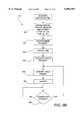
- FIG. 2is a flowchart describing, in relevant part, the general operation of the mobile communication system in accordance with the present invention
- FIG. 3is a schematic diagram showing a general format of an information packet in accordance with the present invention.
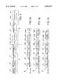
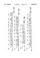
- FIGS. 4a-4jare schematic illustrations representing an exchange of packets for establishing a virtual circuit, session and socket connection between a mobile terminal and another device on the network in accordance with the present invention
- FIGS. 4k-4oare schematic illustrations representing an exchange of data between a mobile terminal and another device before and after the mobile terminal moves from one LAN to another LAN;
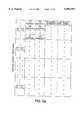
- FIG. 5arepresents a virtual circuit table maintained in memory by each mobile terminal for keeping track of the various virtual circuits which have been established through a gateway with different devices in accordance with the present invention
- FIG. 5brepresents a corresponding virtual circuit table maintained in memory by each gateway for keeping track of the various virtual circuits which have been established through the gateway between various mobile terminals and devices in accordance with the present invention
- FIG. 6is a block diagram of a mobile terminal in accordance with the present invention.
- FIG. 7is a block diagram of an access point in accordance with the present invention.
- FIG. 8is a block diagram of a gateway in accordance with the present invention.
- FIG. 9Ais a flowchart describing, in relevant part, the general operation of the mobile communication system in accordance with another embodiment of the present invention.
- FIG. 9Bis a flowchart describing a routine for establishing a reverse direction link in accordance with the present invention.
- FIGS. 10a-10jare schematic illustrations representing an exchange of packets a between a mobile terminal, gateway and other device for establishing a reverse direction link in accordance with the present invention
- FIG. 11represents a table maintained by a domain name server in accordance with the present invention.
- FIG. 12is a flowchart describing a routine for accomplishing seamless roaming between a LAN and a WAN in accordance with the present invention
- FIG. 13is a block diagram of a gateway in accordance with another embodiment of the present invention.
- FIG. 14is a block diagram of a mobile terminal in accordance with another embodiment of the present invention.
- the present inventionrelates to wireless communication systems which include mobile terminals that can roam from cell to cell and from LAN to LAN.
- mobile terminalscan be data terminals, telephones, pagers, etc.
- each mobile deviceis a mobile data terminal (hereinafter "mobile terminal") used to communicate data such as inventory or the like within a communications system such as a cellular communication system.
- mobile terminalused to communicate data such as inventory or the like within a communications system such as a cellular communication system.
- mobile terminalsused to communicate data such as inventory or the like within a communications system such as a cellular communication system.
- mobile terminalmobile data terminal
- the inventioncontemplates other types of mobile terminals and is not intended to be limited to systems utilizing mobile data terminals.
- Other types of mobile terminalsmay be referred to in the industry as a mobile end system, mobile node, or mobile client, for example.
- the communication system 20includes a plurality of LANs (e.g., LAN1-LAN3) each coupled together via a network backbone 26. Each LAN1-LAN3 itself forms a communication network.
- the LANsare interconnected according to generally known network principles by way of a system backbone 24, and specifically in the present embodiment by a WAN system backbone 24. It shall be appreciated, however, that the system backbone 24 need not be wireless in nature but rather hardwired such as those achieved by connecting to an intranet or internet, for example, which could also serve as the system backbone 24.
- the local area networkcomprises its own network backbone 26.
- the network backbone 26may be a hardwired data communication path made of twisted pair cable, shielded coaxial cable or fiber optic cable, for example, or may be wireless in nature.
- Connected to the network backbone 26are several access points 28, only one of which is shown (namely, access point AP1) for sake of illustration.
- Each access point 28serves as a point through which wireless communications may occur with the network backbone 26.
- one or more wireless access pointsalso may be included in LAN1.
- Each access point 28is capable of wirelessly communicating with other devices within its cell coverage via an antenna 32.
- the cell coverage of the access point 28may take any of several different forms and sizes.
- FIG. 1depicts the access point 28 as utilizing an omni-directional antenna 32 wherein a generally spherical cell area of coverage is obtained.
- a directed yagi-type antenna or other form of antennacould also be used as will be readily appreciated.
- the LAN1also includes one or more mobile terminals 36. For sake of example, only one mobile terminal 36 is shown although it will be appreciated that each LAN is likely to have several mobile terminals 36 associated therewith.
- Each mobile terminal 36communicates with devices on the network backbone 26 of the LAN in which it is registered or, as described below, is capable of communicating with devices on the network backbone 26 of other LANs within the WAN.
- the mobile terminal 36may roam from one cell to another as covered by different access points 28. While roaming within a given LAN, the mobile terminal 36 is configured to associate itself with a new access point 28 in each new cell area according to conventional techniques.
- the mobile terminal 36communicates with the network backbone via wireless communications through the access point 28.
- FIG. 1illustrates in phantom the manner in which a mobile terminal 36 roams from LAN1 to LAN2.
- the mobile terminal 36originally is registered to an access point 28 (AP1) in LAN1.
- the mobile terminal 36originally has a network identification or address which has been assigned to it by virtue of being registered within LAN1.
- the mobile terminal 36moves outside of the cell coverage of access point AP1 and into the cell coverage of an access point 28 (AP2) included in LAN2, the mobile terminal 36 newly registers with the access point AP2.
- the mobile terminal 36receives a new network identification or address by virtue of becoming registered within LAN2.
- each LANalso includes a gateway 40 which serves as an intermediary for communications between the mobile terminal 36 and other devices within the system 20.
- a gateway 40which serves as an intermediary for communications between the mobile terminal 36 and other devices within the system 20.
- Mobile terminals registered with access points 28 on a network backbone 26 other than the network backbone 26 the gateway 40 is connected towould communicate with the gateway 40 via the system backbone 24 discussed above.
- a virtual circuitis established between itself and the gateway 40.
- the network address of the mobile terminal 36may change as a result of the mobile terminal 36 roaming from one LAN to another LAN, the relevant parameters of the corresponding virtual circuit remain the same. Hence, communications between the mobile terminal 36 and a given device are properly routed notwithstanding the change in the network address of the mobile terminal 36. In fact, in the preferred embodiment the devices with which the mobile terminal 36 is communicating remain unaware that the mobile terminal 36 has received a new network address. The manner in which such seamless roaming is carried out is described in more detail below in relation to FIGS. 2-5.
- each LANAlso connected to the network backbone 26 of each LAN is a host computer 42 and a domain name server 44 or other name resolver.
- the host computer 42performs conventional host functions within the respective LAN.
- the host computer 42serves as an interface connection to the system backbone 24 in a conventional manner.
- the gateway 40 or any other LAN devicecould alternatively serve as an interface connection to the system backbone 24.
- the domain name server 44 or other name resolver in each LANperforms the conventional function of providing name to network address mapping for devices within each LAN.
- each LANmay include one or more other devices connected to the network backbone 26. Although not shown, such devices may include work terminals, printers, cash registers, etc.
- FIG. 2the basic operating protocol for a mobile terminal 36 roaming between LANs is shown in accordance with the invention.
- the mobile terminal 36initially powers up and registers within the cell area of an access point 28 (AP1) belonging to LAN1. Thereafter, the mobile terminal 36 will move to LAN2 as represented in FIG. 1 and register with access point AP2 in LAN2. It will be appreciated, however, that the same principles are applied when roaming between any two LANs.
- the mobile terminal 36is powered up and/or reset within the cell coverage of access point AP1.
- the mobile terminal 36registers with the access point AP1 using any of several known conventional techniques, for example. By registering, the access point AP1 assumes responsibility for receiving wireless communications from the mobile terminal 36 and forwarding the communications onto the network backbone 26. Similarly, the access point AP1 assumes responsibility for receiving communications on the network backbone 26 which are destined for the mobile terminal 36. The access point AP1 then forwards such communications wirelessly to the mobile terminal 36.
- the mobile terminal 36obtains a network identification (ID)/address.
- IDnetwork identification
- Such network IDmay be obtained via any of several known conventional techniques in which a unique network ID is assigned to each particular mobile terminal 36 within the LAN1.
- the network ID and/or port IDmay be statically preconfigured within the mobile terminal 36.
- the mobile terminal 36 in step 54obtains a network ID which includes a network address and port in accordance with conventional network protocol(s).
- the mobile terminal 36also obtains the gateway 40 network ID and port ID in a similar fashion.
- the mobile terminal 36may first obtain a link layer ID in accordance with the technique described in commonly assigned, co-pending U.S. patent application Ser. No. 08/778,405, filed Jan. 2, 1997 and entitled "Mobile Device ID Allocation System and Method" which in turn could be used to obtain a network ID.
- the disclosure of the '405 applicationis incorporated herein by reference.
- the mobile terminal 36 in step 56determines if any application program running on the mobile terminal 36 is currently attempting to communicate information to a device on the network backbone 26. If the mobile terminal 36 determines that no information currently needs to be transmitted, the mobile terminal goes to step 57 where it continues all of its other normal operations and returns again to step 56. If, however, the mobile terminal 36 does wish to communicate information to a device on the network, the mobile terminal 36 proceeds to step 58.
- the mobile terminal 36determines if there is an existing session for the mobile terminal 36 to transmit the information it desires. As discussed in more detail below, the mobile terminal 36 may have already established a session with GATEWAY1 to communicate information to other devices throughout the communication system 20. If the mobile terminal 36 determines that a session is established for this information it desires to transmit then the mobile terminal 36 continues to step 60. If not, the mobile terminal 36 continues to step 62 where the mobile terminal determines if a virtual circuit has been established for transmitting the information.
- the mobile terminal 36Prior to being able to transmit the information to a device on the network, the mobile terminal 36 must, in step 60, determine if a socket end point is established (via GATEWAY1) to the device the mobile terminal 36 desires to communicate. Socket end points are frequently established and ended between a mobile terminal 36 and a device on the network and it may even be the case that more than one socket end point is established between a given mobile terminal 36 and a given device to accommodate the transfer of data between application programs running on each. Thus, in step 60, if a socket end point which is able to handle the transfer of current information from the mobile terminal 36 to the device is not established, the mobile terminal establishes such a socket end point.
- the socket end pointis established based on an exchange of a series of packets between the mobile terminal 36 and GATEWAY1. This process is described below in connection with FIGS. 4g-4j.
- communications between the mobile terminal 36 and the deviceoccur in step 67.
- the communicationsoccur via GATEWAY1 serving as an intermediary.
- An example of such communicationis described below in association with FIGS. 4k-4n. It is noted that in this example, the mobile terminal 36 initiated a connection oriented socket end point with the device it desired to communicate, however, connectionless oriented socket end point associations could also be established using conventionally known protocols such as UDP.
- each virtual circuit in the preferred embodimentcan include up to a predefined number of sessions.
- Each sessionin turn, consists of up to a predefined number of sockets.
- the predefined number of sessions and sockets availableare each typically of a very large magnitude (i.e. 2 16 ) and therefore are often considered unlimited.
- step 64the mobile terminal 36 goes to step 64 where it will establish a session within this virtual circuit prior to transferring the information to the device. If a virtual circuit does not exist, the mobile terminal 36 will have to first establish the virtual circuit before establishing the session as discussed below with respect to step 66.
- a sessionis established in accordance with the present invention by exchanging a series of information packets between the mobile terminal 36 and GATEWAY1 as discussed below in relation to FIGS. 4c-4d and 5a-5b.
- address information for the particular device with which the mobile terminal wishes to communicatemay be obtained using well known name resolution techniques.
- the mobile terminal 36may want to communicate with the host computer 42 (HOST1) in LAN1.
- HOST1host computer 42
- the mobile terminal 36 and GATEWAY1exchange a series of packets which results in GATEWAY1 providing the mobile terminal 36 with the network address of the host computer HOST1.
- step 62the mobile terminal 36 determines that no virtual circuit exists for transferring the present information to the device, or if the mobile terminal 36 simply wishes to establish a new virtual circuit, the mobile terminal 36 goes to step 66.
- step 66a virtual circuit between the mobile terminal 36 and GATEWAY1 is established.
- the mobile terminal and GATEWAY1exchange a series of information packets which establishes a virtual circuit entry in corresponding tables stored therein.
- the virtual circuitis used to identify a particular communication connection between the mobile terminal 36 and GATEWAY1 through which connections may be established with devices which the mobile terminal 36 wishes to communicate.
- steps 64 and 60where a session and socket are next established, respectively, within the virtual circuit.
- step 67Once a virtual circuit, session, and socket end point is established and the information is transmitted in step 67, the mobile terminal goes to step 68 to determine if any virtual circuits are to be terminated.
- the mobile terminal 36may conclude that it no longer needs to communicate with the host computer HOST1 and wishes to terminate the connection.
- the GATEWAY1may be responsible for serving as a timekeeper and determining when a virtual circuit is to terminate. The GATEWAY1 in such instance is responsible for informing the mobile terminal 36 that the virtual circuit is about to be terminated. If a virtual circuit is to end as determined in step 68, the system proceeds to step 70 in which the corresponding session and socket connection entries in the tables of the mobile terminal 36 and the GATEWAY1 are cleared as will be better understood in view of the discussion of FIGS. 5a-5b below.
- step 72the mobile terminal 36 determines it has moved to a new LAN (e.g., LAN2).
- a new LANe.g., LAN2
- the manner in which the mobile terminal 36 determines if it has moved to a new LANcan be based on known conventional techniques for determining entry to a new LAN. For example, such determination can be based on the known mobile internet protocol defined in Internet Engineering Task Force (IETF) Spec. R.F.C. 2002. Generally speaking, the mobile terminal 36 upon roaming from LAN1 to LAN2 will proceed beyond the cell coverage of AP1 in LAN1 and will not be able to register with any other access points 28 within LAN 1.
- IETFInternet Engineering Task Force
- the mobile terminal 36will conclude that it has roamed from the previous LAN (LAN 1) to a new LAN (e.g., LAN2) with which it must newly register. It is noted that the steps of determining if a virtual circuit has ended (step 68) and the step of determining if the mobile terminal 36 roamed to a new LAN (step 72) may occur at any instant throughout the process described in FIG. 2 and is only shown at their current locations for discussion purposes only.
- step 74the mobile terminal 36 registers with an access point 28 (e.g., AP2) in the new LAN (e.g., LAN2) in the same manner as was done in step 52. Assuming the mobile terminal 36 has roamed within the cell coverage of the access point AP2, the mobile terminal 36 will thus be able to register with the access point AP2.
- step 76the mobile terminal 36 obtains a new network ID pertaining to the new LAN2. Step 76 is similar to step 54 described above in that the mobile terminal 36 uses conventional techniques to obtain a unique network ID within its local network LAN2.
- the new network ID of the mobile terminal 36 in step 76may be different from the network ID assigned in step 54 in virtually every case.
- step 76packets delivered to the GATEWAY1 for routing to the mobile terminal 36 still may be routed to the mobile terminal 36 by the GATEWAY1 as discussed below in connection with FIG. 40. Accordingly, the system returns to step 66 in which communications can be continued to be carried out seamlessly. If, on the other hand, the mobile terminal 36 does not roam to a new LAN as determined in step 72, the system returns directly to step 56. It is noted that under certain circumstances it may be the case that the mobile terminal 36 ends its session with a host computer or other device without the device knowing the session has ended and therefore communication destined for the mobile terminal 36 in such cases would not be forwarded on the GATEWAY1.
- the packet format shown in FIG. 3includes a number of different fields, some or all of which may be present in a given packet at a given time.
- the packetconsists primarily of a header portion 80 and a payload portion 82.
- the header portion 80is included in all communications in the respective LANs.
- the payload portion 82ordinarily is reserved for data being transferred between two or more devices communicating in a given LAN. According to the present invention, however, the payload portion 82 also is used to communicate information regarding the particular virtual circuit, session, socket, etc. As will be appreciated, this allows the present invention to be carried out in a manner which is transparent to most devices on the network with the exception of the gateway 40 and mobile terminals 36. Thus, the present invention can be incorporated into existing systems with only minor modifications.
- each packetincludes a source address (SA) field which identifies the network address of the device transmitting the packet.
- SAsource address
- DAdestination address
- the packetincludes a source port (SP) field and destination port (DP) field which identify the ports of the devices transmitting and receiving the packet, respectively.
- the packetmay include a globally unique identification (GUID) field used for uniquely identifying a GUID associated with the mobile terminal 36 transmitting the packet.
- GUIDglobally unique identification
- a virtual circuit identification (VCID) fieldis used for identifying a particular virtual circuit associated with the packet transmission.
- a flag (FLG) fieldis used to indicate a change in the network identification of the mobile terminal 36 as will be described below.
- a session identification (SID) field and socket identification (SOID) fieldare used for identifying the particular session and socket, respectively, associated with the packet transmission as will be explained below.
- a command (CMD) fieldis included in the packet for identifying particular functions to be carried out as will be described by way of example below.
- a data (DTA) fieldis used for containing data which is to be transmitted in accordance with the invention.
- each access point 28is configured to recognize a packet which is being transmitted from a mobile terminal 36 which is registered thereto.
- the access point 28receives the packet via its antenna 32 and retransmits its contents onto the network backbone 26 according to known convention.
- the access point 28receives such a packet off the network backbone 26 and retransmits the information to the mobile terminal 36 via its antenna 32 according to known convention.
- the locations of all fixed devices on the respective LANs 1-3 and WAN 22are essentially known based on conventional network routing protocol.
- a packetwill be delivered to the device via appropriate routers, etc.
- the access point AP2 in LAN2can transmit a packet to GATEWAY1 in LAN1 via the WAN backbone 24 according to conventional techniques.
- the mobile terminal 36initially registers to the access point AP1 in LAN1 as shown in FIG. 1.
- the newly registered mobile terminal 36generates and wirelessly transmits a packet 86 to the local gateway 40 (GATEWAY1).
- the mobile terminal 36retrieves its network ID and that of the gateway's 40 if such IDs are not already statically programmed into the mobile terminal 36.
- the SA field and SP field in packet 86include the network address and port of the mobile terminal 36, respectively.
- the DA field and DP fieldinclude the network address and port of the GATEWAY1, respectively.
- the network address and port of the GATEWAY1may be previously obtained by the mobile terminal 36 in a number of different manners.
- each access point 28may be programmed to provide the address and port for the default gateway 40 whenever a mobile terminal 36 newly registers.
- the network address and port for a gateway 40may be statically configured within the mobile terminal 36.
- the GUID field in the packet 86is set to all zeros or some other predefined value to indicate that a GUID has not yet been assigned to the mobile terminal 36.
- the GUIDmay have been previously retrieved or preassigned by the mobile terminal 36. As is described below in relation to FIG. 4b, this prompts the GATEWAY1 to perform a function call to the LAN1 operating system requesting a GUID for the mobile terminal 36.
- the tableconsists of N rows with each row representing a possible virtual circuit (i.e., VC1 through VCN).
- Ncan be any preselected integer which represents the number of virtual circuits the mobile terminal 36 may have established at any given time.
- each virtual circuit entry(VC1 through VCN) has associated therewith L possible sessions (i.e., Session1 through SessionL).
- Lcan be any preselected integer which represents the number of sessions in which the mobile terminal 36 can participate at any given time.
- Each session entry in the tablehas associated therewith a preselected number of possible sockets for representing socket end points in a given session.
- each sessionincludes two sockets (Socket1, Socket2), although a different number is possible.
- Socket1, Socket2For each socket end point there is associated a device (i.e., HOST1) with which the mobile terminal 36 may communicate. As there may be many application programs running on the mobile terminal, there may also be several socket end points for the same device.
- the mobile terminal virtual circuit tableis empty initially and void of any valid columns or rows. As the mobile terminal 36 establishes new virtual circuits, sessions and sockets to establish communication links, entries to the table are inserted with corresponding information from the gateway 40 to indicate which virtual circuits, sessions and sockets are utilized. Thus, the virtual circuit table can dynamically grow in size.
- the mobile terminal 36When a particular virtual circuit, session and/or socket is not in use and/or is terminated, the mobile terminal 36 invalidates or deletes the corresponding entries in the virtual circuit table thereby possibly reducing it in size. Thus, the mobile terminal 36 may always look to the virtual circuit table to see which circuits, sessions and sockets are available and which are in use. It is noted that virtual circuit table could be configured to accept only a limited number of entries or that the virtual circuit table could be static in nature in alternative embodiments.
- FIG. 5ba corresponding virtual circuit table which is stored in memory in each gateway 40 is shown.
- the tableis structured in the same manner as the virtual circuit table described in FIG. 5a and may be static or dynamic in nature.
- the number of virtual circuitswill typically be larger than those found in the mobile terminal 36. This is because each gateway 40 will likely be handling traffic for multiple mobile terminals 36.
- the number of sessions per virtual circuit and sockets per sessionpreferably is the same as that for the mobile terminal 36.
- a given virtual circuit connection between the gateway 40 and the mobile terminalcan provide for L sessions with two or more sockets per session, for example.
- the tableincludes information pertaining to the particular mobile terminal as is discussed below.
- the gateway 40clears any entries which are not in use. Thus, the gateway 40 can look to its virtual circuit table at any time and determine which particular connections are in use and which are available. Although the present embodiment shows all entries related to the virtual circuit, sessions and sockets to be included in a respective single table such as those shown in FIG. 5a and 5b, it will be appreciated that separate tables could be maintained for each and indexed appropriately to provide association.
- the VCID field in the packet 86includes the identification of a mobile terminal virtual circuit which the mobile terminal 36 preselects for purposes of establishing a virtual circuit with the GATEWAY1.
- the mobile terminal 36is configured to look to its virtual circuit table (FIG. 5a) and select a particular virtual circuit (e.g., VC1-VCN) which is presently available.
- the mobile terminal 36selects one of the virtual circuits (nominally labeled MT VCID) and includes it the VCID field. This serves to inform the GATEWAY1 of the particular virtual circuit label the mobile terminal 36 is using to represent the connection which is to be established.
- the CMD fieldincludes a predefined function call "VCKT -- START" intended to inform the GATEWAY1 that the mobile terminal 36 wishes to establish a virtual circuit.
- the mobile terminal 36then transmits the packet 86 wirelessly to the GATEWAY1 via the access point AP1.
- the GATEWAY1receives the packet 86 and processes the packet as follows.
- the GATEWAY1recognizes the VCKT -- START command and looks to its virtual circuit table (FIG. 5b) in order to select a particular virtual circuit (e.g., VC1-VCZ) which is presently available.
- the GATEWAY1selects a particular virtual circuit (e.g., VC1) based on what is available (i.e., not in use).
- the GATEWAY1then stores in its table in association with the selected virtual circuit entry the MT VCID obtained from the VCID field of the packet 86.
- the selected virtual circuitthereby becomes associated with the virtual circuit identified by MT VCID.
- the GATEWAY1is configured to detect the presence of all zeros in the GUID field. In response, the GATEWAY1 performs a function call to the operating system of the LAN1 to obtain a GUID for the mobile terminal 36.
- the manner in which the operating system can provide such GUIDis known in the art.
- the GATEWAY1In response to the packet 86, the GATEWAY1 generates a packet 88 as shown in FIG. 4b.
- the purpose of the packet 88is to inform the mobile terminal 36 that a virtual circuit has been established and to notify the mobile terminal 36 of the particular virtual circuit label being used to define the connection by the GATEWAY1.
- the packet 88is used to inform the mobile terminal 36 of the particular GUID which is being assigned thereto.
- the SA and SP fields of the packet 88correspond to the address and port of the GATEWAY1, respectively.
- the DA and DP fields of the packet 88correspond to the address and port of the mobile terminal 36, respectively, as obtained from the SA and SP fields of packet 86.
- the GUID fieldcontains the GUID for the mobile terminal 36 (MT GUID) as obtained from the operating system.
- the VCID fieldcontains the virtual circuit selected by the GATEWAY1 (nominally labeled GW1 VCID).
- the CMD fieldcontains the predefined command "VCKT -- STARTED" to
- the GATEWAY1then proceeds to transmit the packet 88 to the mobile terminal 36 via the access point AP1.
- the mobile terminal 36receives the packet 88 and processes the packet 88 by storing in memory the MT GUID.
- the mobile terminal 36stores in its virtual table entry for MT VCID the corresponding GW1 VCID as obtained from the VCID field of the packet 88.
- the mobile terminal 36generates a packet 90 to be sent to the GATEWAY1 as represented in FIG. 4c.
- the header portion of the packet 90is identical to that of packet 86 (FIG. 4a).
- the VCID fieldincludes the GW1 VCID assigned to the virtual circuit by the GATEWAY1 (as obtained from the virtual circuit table of the mobile terminal 36).
- the mobile terminal 36includes the identity of a session which the mobile terminal 36 selects for purposes of establishing the session. Specifically, the mobile terminal 36 again refers to its virtual circuit table (FIG. 5a) and selects a particular session (e.g., Session1) which is available within the previously selected virtual circuit (e.g., VC1).
- the mobile terminal 36includes the session (nominally labeled MT SID) in the SID field of the packet 90.
- the mobile terminal 36includes the predefined command "START -- SESSION" in the CMD field to notify the GATEWAY1 that the mobile terminal 36 wishes to start a session. The mobile terminal 36 then proceeds to transmit the packet 90 to the GATEWAY1.
- the GATEWAY1receives the packet 90.
- the GATEWAY1is configured to again look to its virtual circuit table (FIG. 5b) for the virtual circuit corresponding to the GW1 VCID identified in the VCID field. Specifically, the GATEWAY1 selects a particular session which is available in conjunction with the GW1 VCID previously selected for purposes of generating the packet 88. The GATEWAY1 then proceeds to store in the table entry corresponding to the selected session the session identification (MT SID) selected by the mobile terminal 36 as provided in the SID field of the packet 90.
- MT SIDsession identification
- the GATEWAY1then proceeds to generate a response packet 92 as shown in FIG. 4d.
- the purpose of the response packet 92is to inform the mobile terminal 36 of the particular session label which the GATEWAY1 is assigning to the virtual circuit connection.
- the header portionis again standard and is identical to the header portion included in the packet 88.
- the VCID fieldincludes the MT VCID for the virtual circuit as obtained from the virtual circuit table of the GATEWAY1 corresponding to the entry for GW1 VCID.
- the SID fieldincludes the particular session (nominally labeled GW1 SID) selected by the GATEWAY1 in response to the packet 90.
- the CMD fieldincludes a predefined command "SESSlON -- STARTED" indicating to the mobile terminal 36 that the gateway has selected a corresponding session.
- the GATEWAY1then proceeds to transmit the packet 92 to the mobile terminal 36.
- the mobile terminal 36receives the packet 92 and looks to the entry in its virtual circuit table corresponding to the MT VCID identified in the VCID field of the packet 92. The mobile terminal 36 then proceeds to store in its virtual circuit table the GW1 SID obtained from the SID field of the packet 92 in association with the particular session identified in the SID field of the packet 90. Thus, a virtual circuit and session are established between the mobile terminal 36 and the GATEWAY1 based on an exchange of the packets represented in FIGS. 4a-4d. The mobile terminal 36 and the GATEWAY1 each know the corresponding VCID and SID for the other device.
- the mobile terminal 36will need to obtain network addressing information for the device on the network with which it desires to communicate in order to establish a socket connection with a particular device on the network.
- the mobile terminal 36wishes to communicate with the host computer HOST1 in the LAN1.
- the mobile terminal 36is configured to first generate a packet 94 as shown in FIG. 4e for the purpose of requesting address information.
- the packet 94is to be transmitted to the GATEWAY1 and hence has a header portion similar to that described above in connection with the packet 86.
- the VCID and SID fieldsinclude the GW1 VCID and GW1 SID information, respectively, corresponding to the particular virtual circuit and session the requested address information will relate to.
- the CMD fieldincludes a predefined command "GET -- HOST -- BY -- NAME" or some other command identifying the particular device with which the mobile terminal 36 wishes to communicate.
- the DTA field of the packet 94includes the particular name of the device (e.g., HOST1 NAME).
- the packet 94is transmitted to the GATEWAY1 which is configured to retrieve the device name from the DTA field and query the local name resolver such as DNS 44 for the corresponding network address.
- the GATEWAY1generates a response packet 96 as shown in FIG. 4f which is to be transmitted to the mobile terminal 36 with the appropriate header portion.
- the packet 96includes the MT VCID and MT SID in the VCID and SID fields, respectively, as obtained from the virtual circuit table of the GATEWAY1, such identifications corresponding to the particular virtual circuit and session identified in the VCID and SID fields of the packet 94.
- the CMD fieldincludes the predefined command GOT -- HOST -- BY -- NAME informing the mobile terminal of the purpose of the packet.
- the DTA fieldcontains the actual network address(es) of the HOST1 as requested.
- the packet 96is transmitted to the mobile terminal 36 which receives the packet and stores the network address.
- Step 60 of FIG. 2relates to establishing the actual socket connection between the mobile terminal 36 and the GATEWAY1.
- Such procedurebegins with the mobile terminal 36 generating a packet 98 to be transmitted to the GATEWAY1 as shown in FIG. 4g.
- the packet 98includes a header portion directing the packet to the GATEWAY1.
- the packet 98includes the virtual circuit and session identifiers GW1 VCID and GW1 SID for the GATEWAY1 in the corresponding fields.
- the mobile terminal 36is able to obtain such information from the corresponding entries in its virtual circuit table (FIG. 5a).
- the mobile terminal 36With respect to the SOID field, the mobile terminal 36 now looks to its virtual circuit table and selects an available socket corresponding to the previously selected virtual circuit and session.
- the mobile terminal 36selects such a socket (nominally labeled MT SOID) and includes it in the SOID field of the packet 98.
- the CMD fieldincludes a predefined "START -- SOCKET” command informing the GATEWAY1 that it is desired to allocate a socket endpoint.
- the packet 98is transmitted to the GATEWAY1 where it is processed as follows. Specifically, the GATEWAY1 selects an available socket corresponding to the information provided in the VCID and SID fields of the packet 98. The GATEWAY1 then stores in association with the selected socket the MT SOID provided in the SOID field of the packet 98. The GATEWAY1 then generates a response packet 100 to be transmitted to the mobile terminal 36 having the format shown in FIG. 4h. Following the standard header portion, the packet 100 includes the MT VCID and MT SID information in the VCID and SID fields similar to the packet 96. In the SOID field, the GATEWAY1 includes the particular socket (nominally labeled GW1 SOID) which was selected from its virtual circuit table (FIG. 5b) in response to the packet 98. Finally, the CMD field includes a predefined command "SOCKET -- STARTED" indicating to the mobile terminal 36 that a socket has been established. The packet 100 is then transmitted to the mobile terminal 36.
- the mobile terminalreceives the packet 100 and proceeds to store the gateway socket information GW1 SOID in its virtual circuit table in association with the mobile terminal socket identified in the SOID field of the packet 98.
- the mobile terminal 36 and the GATEWAY1have established a unique virtual circuit defined by a VCID, SID and SOID combination.
- the mobile terminal 36 and the GATEWAY1each has stored in its virtual circuit table the VCID, SID and SOID combination both from the perspective of the mobile terminal 36 and the GATEWAY1.
- the mobile terminal 36attempts to begin actual communications (FIG. 2, step 67) with the particular device (e.g., the HOST1). Initially, however, the mobile terminal 36 generates a packet 102 as shown in FIG. 4i.
- the packet 102is addressed to the GATEWAY1 and serves the purpose of requesting that the GATEWAY1 obtain a conventional network connection with the HOST1.
- the packet 102has a standard header portion addressed to the GATEWAY1.
- the VCID, SID and SOID fieldsinclude the virtual circuit, session and socket information from the perspective of the GATEWAY1, i.e,, GW1 VCID, GW1 SID and GW1 SOID, respectively.
- the CMD fieldincludes the predefined CONNECT command notifying the GATEWAY1 of the desire to establish a connection between the gateway and the HOST1.
- the DTA fieldincludes the actual network address of the HOST1 as obtained from packet 96 discussed above. It is noted that by this time the mobile terminal 36 has stored in the device entry of its virtual circuit table corresponding to the particular socket the identity of the particular device (e.g., the HOST1) and the gateway address and port corresponding to the GATEWAY1. This facilitates the mobile terminal 36 keeping track of such information when establishing virtual circuits with several such gateways 40 and devices in the network.
- the packet 102is transmitted to the GATEWAY1 which receives the packet.
- the GATEWAY1utilizes conventional network techniques to prepare and/or establish a connection between the GATEWAY1 and the HOST1 as identified in the DTA field of the packet 102.
- the GATEWAY1generates a response packet 104 as shown in FIG. 4j.
- the packet 104includes the standard header portion in order to be transmitted from the GATEWAY1 to the mobile terminal 36.
- the packet 104includes the corresponding VCID, SID and SOID of the mobile terminal 36 in the appropriate fields.
- the CMD fieldincludes a predefined command "CONNECT -- RESPONSE" intended to notify the mobile terminal 36 that the connection between the GATEWAY1 and the HOST1 is prepared and/or established.
- the GATEWAY1has stored in its mobile terminal entry of its virtual circuit table corresponding to the particular socket, the mobile terminal 36 address, port, and GUID. This facilitates the GATEWAY1 keeping track of which particular mobile terminal 36 is being handled by the respective virtual circuits.
- the mobile terminal entry of the virtual circuit tablehas stored therein the network address of the device (e.g. HOST1) with which the mobile terminal 36 is communicating via the particular virtual circuit connection.
- the GATEWAY1will also store in the mobile terminal entry of the table the particular port being used by the GATEWAY1 for communications with the HOST1 with respect to the specific socket connection.
- FIG. 4killustrates a packet 106 containing data which the mobile terminal 36 wishes to transmit to the HOST1.
- the data stored in packet 106is directed via the GATEWAY1 using the socket end points previously established for communications between the mobile terminal 36 and the HOST1.
- the header portionagain includes the address and port of the GATEWAY1 in the DA and DP fields, respectively.
- the VCID, SID and SOID fieldsdefine the complete connection from the perspective of the GATEWAY1 as obtained from the corresponding entries in the virtual circuit table of the mobile terminal 36.
- the CMD fieldincludes the predefined command "SEND -- DATA" informing the GATEWAY1 that the data is to be delivered to the corresponding device (i,e., the HOST1).
- the DTA fieldincludes the actual data which is to be delivered to the HOST1.
- the packet 106is then transmitted to the GATEWAY1.
- the GATEWAY1receives the packet 106 and in response to the SEND -- DATA command looks up the virtual circuit entry in its virtual circuit table corresponding to the information included in the VCID, SID and SOID fields of the packet 106. Based on this information the GATEWAY1 obtains the address information of the HOST1 from the corresponding mobile entry in its virtual circuit table. The GATEWAY1 then generates a packet 108 as shown in FIG. 4l to be sent to the HOST1.
- the SA field and SP fieldcorrespond to the address and port of the GATEWAY1.
- the port utilized by the GATEWAY1 to communicate directly with the HOST1 (or other device)is selected by the GATEWAY1 so as to be unique to the corresponding socket of the virtual circuit.
- the DA field and DP fieldcorrespond to the address and port of the HOST1 as previously obtained and stored in the virtual circuit table.
- the DTA fieldcontains the data included in the DTA field in the packet 106 from the mobile terminal 36. It is noted that the packet 108 follows a conventional format native to the end point with which the mobile terminal 36 is communicating.
- FIG. 4mrepresents a packet 110 indicative of a communication sent back to the GATEWAY1 by the HOST1 in response to the packet 108.
- the DTA field of the packet 110includes appropriate response data which ultimately is intended for the mobile terminal 36. Since the port identified in the DP field is selected to be unique to a given socket in the virtual circuit table of the GATEWAY1, the GATEWAY1 identifies such socket based on the information stored in the table as discussed above. From the unique gateway port, the GATEWAY1 is able to identify the VCID, SID and SOID of the mobile terminal 36 from the virtual circuit table. The GATEWAY1 then generates a packet 112 as shown in FIG. 4n which is to be transmitted back to the mobile terminal 36.
- the packet 112includes the address and port of the mobile terminal 36 in the DA and DP fields, respectively, as obtained from the mobile entry of the virtual circuit table of the GATEWAY1.
- the DTA fieldincludes the data from the DTA field received in the packet 110 from the HOST1.
- communications between the mobile terminal 36 and the HOST1can remain ongoing via an exchange of packets as represented in FIGS. 4k-4n.
- the GATEWAY1simply determines where to direct a received packet based on the contents of its virtual circuit table.
- the mobile terminal 36will roam to another LAN (e.g., LAN2) as outlined above. However, as will be apparent such roaming does not have an adverse affect on the virtual circuits formed via the GATEWAY1. Namely, referring back to FIG. 2 assume that the mobile terminal 36 does roam from LAN1 to LAN2. Such roaming is detected in step 72 and the mobile terminal 36 registers with a new access point (e.g., AP2) and obtains a new network identification (e.g., MT ADDRESS* and MT PORT*) (steps 74 and 76). However, the contents of the virtual circuit table (FIG. 5a) of the mobile terminal 36 remain unchanged.
- a new access pointe.g., AP2
- MT ADDRESS* and MT PORT*e.g., MT ADDRESS* and MT PORT*
- the mobile terminal 36wants to continue communicating with the HOST1 in LAN1.
- the mobile terminal 36simply generates a packet 114 as shown in FIG. 4o.
- the source address SA and source port SP fields in the packet 114will reflect the new network address of the mobile terminal 36 as a result of roaming to LAN2.
- the mobile terminal 36continues to communicate with the HOST1 via the GATEWAY1 and the specific virtual circuit.
- the packet 114includes the address and port of the GATEWAY1 in the DA and DP fields as shown.
- the packet 114similar to the packet 106, includes the GW1 VCID, GW1 SID and GW1 SOID in the respective fields identifying the particular virtual circuit.
- the CMD fieldcontains the same "SEND -- DATA" command as the packet 106, and the data which is to be transmitted to the HOST1 is included in the DTA field.
- the packet 114includes the flag field FLG in which the flag is set to indicate to the GATEWAY1 that the address of the mobile terminal 36 has changed. The packet 114 is then sent to the GATEWAY1 via the access point AP2 and known routing techniques across the WAN 22.
- the GATEWAY1receives the packet 114 and processes the packet in the same manner described above in relation to packet 106 (FIG. 4k) with the following exception.
- the GATEWAY1detects from the FLG field that the address of the mobile terminal 36 has changed.
- the GATEWAY1updates its virtual circuit table (FIG. 5b) so as to now include the updated address of the mobile terminal 36 in the corresponding mobile entry.
- Such updated addressis obtained via the SA field and SP field of the packet 114.
- the GATEWAY1continues to act as an intermediary and forwards the data in the DTA field to the HOST1 in a packet in the exact same manner as described above in relation to packet 108 (FIG. 4l). In other words, the same procedures described above in relation to FIGS.
- the HOST1is able to continue communicating with the mobile terminal 36, and vice versa, regardless of the fact that the network address of the mobile terminal 36 has changed.
- the mobile terminal 36 in the present embodimentis configured to send a gratuitous update packet to the GATEWAY1 in which the FLG field is set so that the GATEWAY1 can immediately update is tables and continue forwarding packets to the mobile terminal 36. Accordingly, seamless roaming is achieved.
- FIG. 6is a block diagram representing the basic structure of the mobile terminals 36 according to the exemplary embodiment.
- Each mobile terminal 36includes a processor 170 which can be programmed to control and to operate the various components within the mobile terminal 36 in order to carry out the various functions described herein.
- the processor 170is coupled to an operator input device 172 which allows an operator to input data to be communicated to the corresponding LAN such as inventory data, patient information, etc. This information may be sent to the host computer 42 which serves as a central data location, for example, or to a cash register connected to the network backbone 26, as another example, for providing price information.
- the input device 172can include such items as a keypad, touch sensitive display, etc.
- the mobile terminal 36also may include a bar code scanner 173 coupled to the processor 170 for providing another form of data input.
- a display 174is also connected to and controlled by the processor 170 via a display driver circuit 175.
- the display 174serves as a means for displaying information stored within the mobile terminal 36 and/or received over the network backbone 26 via an access point 28.
- the display 174can be a flat panel liquid crystal display with alphanumeric capabilities, for example, or any other type of display as will be appreciated.
- a memory 176is included in each mobile terminal 36 for storing program code executed by the processor 170 for carrying out the functions described herein.
- the actual code for performing such functionscould be easily programmed by a person having ordinary skill in the art of computer programming in any of a number of conventional programming languages based on the disclosure herein. Consequently, further detail as to the particular code has been omitted for sake of brevity.
- the memory 176also serves as a storage medium for storing the above described virtual circuit table for the mobile terminal 36.
- Each mobile terminal 36also includes its own RF section 178 connected to the processor 170.
- the RF section 178includes an RF receiver 182 which receives RF transmissions from an access point 28 and via an antenna 184 and demodulates the signal to obtain the digital information modulated therein.
- An example of a suitable RF receiver 182 for use in the mobile terminal 106is the Model 025 Direct Sequence Spread Spectrum Radio Module, which is commercially available from Aironet Wireless Communications, Inc. of Akron, Ohio.
- the RF section 178also includes an RF transmitter 186.
- the processor 170forms within the memory 176 the aforementioned information packets.
- the information packetsare delivered to the RF transmitter 186 which transmits an RF signal with the information packet modulated thereon via the antenna 184 to the access point 28 with which the mobile terminal 36 is registered.
- Each access point 28is connected to the network backbone 26 via a connector 240 such as a DB-9 or RJ-45 connector.
- the connector 240is connected to the network backbone 26 at one end and to a network adapter transceiver 252 included in the base station 108 at the other end.
- the network adapter transceiver 252is configured according to conventional network adapter transceiver techniques to allow the access point 28 to communicate over the network backbone 26.
- the network adapter transceiver 252is also connected to an internal bus 254 included within the access point 28.
- the access point 28further includes a processor 256 connected to the bus 254 for controlling and carrying out the operations of the access point 28.
- the processor 256may include any of a variety of different microprocessors, such as the Motorola 68360 (25MHz) or Intel 80386 microprocessors.
- the access point 28also includes a memory 258 connected to the bus 254.
- the memory 258stores program code executed by the processor 256 to control the other elements within the access point 28 to carry out the functions described herein. It will be readily apparent to a person having ordinary skill in the art of computer programming how to program the processor 256 and the other elements within the access point 28 to carry out the operations described herein using conventional programming techniques based on the flowcharts and descriptions provided herein. As a result, additional detail as to the specific program code has been omitted.
- the memory 258functions to store information tables maintained by the processor 256 including information such as a list of the mobile terminals 36 which are currently registered with the access point 28.
- the RF section 260includes the aforementioned antenna 32 for receiving radio signals from and transmitting radio signals to mobile terminals 36 within the cell area of the access point 28.
- Information transmitted from a mobile terminal 36is received via the antenna 32 and is processed by an RF receiver 262 which demodulates and decodes the signal and converts the information to a digital signal having the aforementioned packet format.
- the processor 256stores the packet in the memory 258 until such time as the base station 108 is able to transmit the information packet onto the network backbone 26 via the network adapter transceiver 252 and connector 240.
- Information packets which are transmitted to the access point 28 via the network backbone 26 for transmission to a mobile terminal 36are received by the network transceiver 252.
- the processor 256controls an RF transmitter 264 included in the RF section 260, the RF transmitter 264 also being connected to the bus 254.
- the processor 256causes the RF transmitter 264 to modulate an RF signal using spread spectrum techniques, for example, which in turn carries the information packet to the appropriate mobile terminal 36.
- FIG. 8represents a block diagram of a gateway 40 in accordance with the present invention.
- Each gateway 40is connected to the network backbone 26 via a connector 340 such as a DB-9 or RJ-45 connector.
- the connector 340is connected to the network backbone 26 at one end and to a network adapter transceiver 352 included in the gateway 40 at the other end.
- the network adapter transceiver 352is configured according to conventional network adapter transceiver techniques to allow the gateway 40 to communicate over the network backbone 26.
- the network adapter transceiver 352is also connected to an internal bus 354 included within the gateway 40.
- the gateway 40further includes a processor 356 connected to the bus 354 for controlling and carrying out the operations of the gateway 40.
- the gateway 40also includes a memory 358 connected to the bus 354.
- the memory 358stores program code executed by the processor 356 to control the other elements within the gateway 40 to carry out the functions described herein. It will be readily apparent to a person having ordinary skill in the art of computer programming how to program the processor 356 and the other elements within the gateway 40 to carry out the operations described herein using conventional programming techniques based on the flowcharts and descriptions provided herein. As a result, additional detail as to the specific program code has been omitted.
- the memory 358functions to store the aforementioned virtual circuit table (FIG. 5b) for the gateway 40.
- each mobile terminal 36may establish what is referred to herein as a reverse direction communication link with a corresponding gateway 40 as part of its operation procedure.
- the gateway 40is readied to act as an intermediary between the mobile terminal 36 and any device in the system 20 which may want to initiate communication with the mobile terminal 36.
- the DNS 44 or other name resolver responsible for the particular mobile terminal 36is updated with the network address of the mobile terminal 36 from the point of view of the gateway 40 as a result of the mobile terminal 36 desiring to accept information or incoming connections from an initiating device or host computer 42.
- Devices desiring to communicate with a particular mobile terminal 36initially query the DNS 44 or other name resolver to obtain the network address of the particular mobile terminal 36, such network address actually being a "virtual" address representative of the mobile terminal 36 as provided by the gateway 40 as discussed below.
- the DNS 44 or other name resolverprovides such address to the initiating device.
- the intiating devicetransmits a packet directed to the virtual address of the particular mobile terminal 36 as obtained from the DNS 44.
- the gateway 40is configured to receive any packets directed to a virtual address of a mobile terminal 36 in its virtual circuit table. The gateway 40 then forwards the packet to the mobile terminal 36 via its virtual circuit. The mobile terminal 36 in turn responds to the packet by transmitting a packet to the gateway 40 via the virtual circuit. The gateway 40 thereafter forwards the response packet to the initiating device with the source address field set to the virtual address. The gateway 40 maintains the current network address of the mobile terminal 36 even as the mobile terminal 36 roams from LAN to LAN as described above. Hence, the gateway 40 is able to continuously forward packets directed to the mobile terminal's 36 virtual address to the mobile terminal itself.
- each mobile terminal 36proceeds to step 370 following step 54.
- step 370a mobile terminal 36 establishes a reverse direction communication link with a gateway 40.
- the details of step 370are described below in connection with FIG. 9B.
- the mobile terminal 36is able to receive communications initiated by other devices.
- the mobile terminal 36 and systemthen proceeds to steps 56 et seq.
- FIG. 9Billustrates in detail step 370 for establishing the reverse direction communication link.
- an exemplary mobile terminal 36 and gateway 40e.g., GATEWAYL
- VIDvirtual circuit
- SIDsession
- SOIDsocket
- the virtual circuit, session and socketare established by exchanging packets and information in the manner described above in relation to FIGS. 4a-4d and 4g-4h.
- the mobile terminal 36allocates a socket end point with the gateway 40 independent of any particular end device.
- the packets described above with respect to FIGS. 4e and 4fare not relevant in the present situation.
- step 374the mobile terminal 36 and GATEWAY1 execute a bind request/response transaction as is discussed more fully below in accordance with FIGS. 10a and 10b.
- the bind request/response transactionestablishes the virtual identity that the GATEWAY1 uses to impersonate the mobile terminal 36 for purposes of receiving unsolicited information and connections.
- the bind requestis referenced to a specific port number although other demultiplexing identifiers could be used other than port numbers in another embodiment.
- the GATEWAY1responds to the bind request in step 378 by updating the DNS 44 (e.g., DNS1) or other name resolver responsible for providing the name to network address mapping for the mobile terminal 36.
- the GATEWAY1updates the DNS1 with the virtual address assigned by the GATEWAY1 for the name corresponding to mobile terminal 36. This virtual address for the mobile terminal 36 uniquely identifies the mobile terminal 36 for the duration of the session.
- Such updating of the DNS 44 or other name resolveris performed using known techniques.
- step 379the mobile terminal 36 and the GATEWAY1 execute a listen request/response transaction as is described in more detail below in relation to FIGS. 10c-10d.
- the listen request/response transactionis utilized to inform the GATEWAY1 of the mobile terminal's 36 willingness to receive unsolicited information and/or connections via the gateway.
- the DNS1provides the querying device with the virtual address of the mobile terminal 36.
- the network address of the mobile terminal 36 as stored in the DNS1is its virtual address identified by the GATEWAY1.
- the GATEWAY1is configured to listen for any information directed to a mobile terminal's 36 virtual address included in its virtual circuit table (FIG. 5b). Using known techniques, the GATEWAY1 receives the information directed to the virtual address of the mobile terminal 36 by accepting connections and/or information from devices initiating communications directed to the virtual address of the mobile terminal 36.
- the GATEWAY1forwards the information to the mobile terminal via the corresponding virtual circuit connection previously established between the GATEWAY1 and the mobile terminal 36.
- the mobile terminal 36may respond to such information and if it does its via the GATEWAY1. If the mobile terminal 36 responds, the GATEWAY1 receives the response information from the mobile terminal 36 and forwards such information to the initiating device.
- the mobile terminal 36then roams to another LAN or WAN and receives another network address (e.g., steps 72, 74 and 76 in FIG. 9A), the mobile terminal 36 updates the GATEWAY1 with its new address via the flag field FLG as described above in relation to FIG. 4o.
- the mobile terminal 36 in step 380sends information to the GATEWAY1 identifying a child socket end point that will be utilized by the GATEWAY1 when initiating devices attempt to communicate with the mobile terminal 36.
- the GATEWAY1logs the child socket end point into its virtual circuit table for the corresponding (parent) socket end point established in step 372. For a given (parent) socket created in step 372 there may be multiple child socket end points allocated.
- the child socket(s)are used to uniquely identify communication relationships between the mobile terminal 36 and an initiating device. Each child socket, once utilized, becomes a completed socket end point and, if necessary, the mobile terminal 36 may create a new child socket if it desires to establish additional communication relationships.
- the mobile terminal 36 in step 382issues (see, e.g., FIG. 10e) "ACCEPT" commands to the GATEWAY1 indicating that the mobile terminal 36 is prepared to receive any unsolicited connection(s) via the specified child socket.
- the GATEWAY1provides the resources to handle up to a bounded number of simultaneous unsolicited requests, whereby such number may be specified by the mobile terminal 36.
- the GATEWAY1queues connection requests from the initiating device(s). Each time an initiating device attempts to establish a connection with the mobile terminal 36, the GATEWAY1 establishes a relationship between the incoming connection request and an available child socket. After the GATEWAY1 establishes the relationship, it completes the accept transaction with the mobile terminal 36.
- the mobile terminal 36may return to step 380.
- connection type protocolIn another embodiment, a connectionless protocol may be used to establish the respective links. In such case, it will be appreciated that only the bind request/response transaction would be necessary.
- FIG. 10aillustrates an exemplary packet 390 sent by the mobile terminal 36 to the GATEWAY1 in step 374 (FIG. 9B) in order to initiate a bind request.
- the SA, DA, SP, DP, VCID, FLG, SID and SOID fieldsare all ascertained and utilized in the same manner as described above in connection with the previous embodiment.
- the CMD fieldincludes the command "BIND REQUEST" which notifies the GATEWAY1 that the packet 390 represents a bind request.
- the packet 390also includes a field PORT in which the mobile terminal 36 identifies a particular port to which communications are to be directed.
- the GATEWAY1initializes itself for establishing a reverse communication link and sends the mobile terminal 36 a bind reply packet 392 as shown in FIG. 10b.
- the CMD fieldincludes the command "BIND -- REPLY" which notifies the mobile terminal 36 that the bind request has been received and processed.
- FIG. 10cillustrates a packet 394 sent by the mobile terminal 36 to the GATEWAY1 in step 379 as part of executing the listen request.
- the CMD fieldincludes the command "LISTEN -- REQUEST" which prompts the GATEWAY1 to prepare itself to receive unsolicited connections intended for the mobile terminal 36.
- the GATEWAY1assigns a unique virtual address to the mobile terminal 36 and informs the DNS1 or other name resolver of the mobile terminal's 36 virtual address.
- FIG. 10dillustrates a packet 398 sent by the GATEWAY1 to the mobile terminal 36 in step 379 in response to the listen request packet 394.
- the CMD fieldincludes the command "LISTEN -- REPLY" which is intended to inform the mobile terminal 36 that the listen request has been received and processed.
- FIG. 10eexemplifies a packet 400 sent by the mobile terminal 36 to the GATEWAY1 in step 380.
- the DTA fieldincludes the particular child socket(s) identified by the mobile terminal 36 as part of step 380.
- the CMD fieldincludes the command "ACCEPT" which notifies the GATEWAY1 that the mobile terminal 36 is ready to accept any connections initiated by another device.
- FIG. 10frepresents a packet 406 generated by the GATEWAY1 in response to the packet 400 in step 382 (FIG. 9B).
- the CMD fieldincludes the command "ACCEPT -- RESPONSE" to notify the mobile terminal 36 that the communications relationship between the GATEWAY1 and the initiating device is established.
- the mobile terminal 36will generate and send a packet 407 as shown in FIG. 10f' to the GATEWAY1.
- the CMD fieldincludes the command "RECEIVE -- DATA" which informs the GATEWAY1 that the mobile terminal 36 presently is waiting to receive data which the GATEWAY1 receives from an initiating device.
- the host computer HOST1then wishes to initiate communication with the mobile terminal 36.
- the device attempting to initiate the communication with the mobile terminal 36will not know the network address of the mobile terminal 36 beforehand.
- the HOST1queries the DNS1 or other name resolver, using conventional techniques, for the network address of the mobile terminal 36.
- the DNS1looks to its table (FIG. 11) to find the corresponding address for the mobile terminal 36 (which is actually the "virtual" address as provided by the GATEWAY1).
- the DNS1responds to the HOST1 with the "Virtual" address of the mobile terminal 36.
- FIG. 10grepresents a packet 408 which is then sent by the HOST1 "to" the mobile terminal 36.
- the destination address in the DA fieldis the virtual address of the mobile terminal 36 as provided to the HOST1 by the DNS1 or other name resolver.
- the port number in the DP fieldis the port number for the mobile terminal 36 as provided by known standards or predetermined application end points.
- the DTA field of the packet 408includes information the HOST1 intends to send to the mobile terminal 36.
- the GATEWAY1is configured to receive network transmissions directed to mobile terminals virtual addresses by virtue of recognizing the virtual addresses included therein. Hence, the GATEWAY1 will receive the packet 408 based on its being addressed to the virtual address of the mobile terminal 36.
- the GATEWAYis configured to generate and transmit a packet 410 in response to the packet 408 as shown in FIG. 10h.
- the packet 410is directed to the mobile terminal 36 via the virtual circuit connection and corresponding receive request 407.
- the DTA fieldincludes the data received by the GATEWAY1 from the HOST1 in the packet 408.
- the CMD fieldincludes the command "RECEIVE -- RESPONSE" indicating the nature of the packet.
- the mobile terminal 36receives the packet 410 and processes the data in accordance with the particular application being carried out by the mobile terminal. Upon completion of such processing, the details of which are not relevant to the invention, the mobile terminal 36 may generate a response packet 412 as represented in FIG. 10i.
- the response packet 412is sent from the mobile terminal 36 to the GATEWAY1 and includes in the DTA field the response data intended to be forwarded to the HOST1.
- the CMD fieldincludes the command "SEND -- DATA" indicating that the data is intended to be forwarded.
- the GATEWAY1receives the packet 412 and based on the SOID field knows which device (e.g., the HOST1) the response data is to be forwarded to.
- the GATEWAY1proceeds to generate a packet 414 as shown in FIG. 10j which is then sent from the GATEWAY1 to the HOST1.
- the DTA field of the packet 414includes the response data received by the GATEWAY1 in the response packet 412.
- the packet 414includes the virtual address of the mobile terminal 36 in the source address (SA) field so as to appear as if the packet originates from the mobile terminal 36 itself, at least from the perspective of the HOST1.
- SAsource address
- the subject embodiment of the present inventionallows for a device such as a host computer or the like to initiate communication with the mobile terminal 36 via the gateway 40.
- a devicesuch as a host computer or the like to initiate communication with the mobile terminal 36 via the gateway 40.
- the contents of the gateway 40are updated to reflect the new address of the mobile terminal 36, if any.
- the mobile terminal 36notifies the gateway 40 of its new address via a notification packet with the FLG set to indicate a new address.
- the gateway 40in turn updates the actual address for the mobile terminal 36 in its tables.
- packets which continue to be directed to the mobile terminal 36 from other devices via the virtual address utilized by the gateway 40will be forwarded to the new address of the mobile terminal 36 by the gateway 40.
- seamless communicationis achieved both for communications initiated by the mobile terminal 36 and communications initiated by another device.
- FIGS. 12-13relate to an embodiment of the present invention in which mobile terminals 36 may roam from LAN to WAN seamlessly.
- the WAN backbone 24includes WAN access points 500 distributed throughout as represented in FIG. 13.
- the WAN access points 500are distributed throughout the WAN backbone 24 area similar to the access points 28 being distributed throughout the various LANs as discussed above.
- the WAN access points 500are operationally similar to the access points 28, but cover substantially broader cell areas which encompass the WAN.
- Each gateway 40is coupled via a hardwired or wireless connection with the WAN backbone 24 via a WAN network adapter transceiver 502 included in the gateway 40.
- Each WAN access point 500includes a WAN transceiver (not shown) having an RF receiver and transmitter for receiving and transmitting information packets similar to the RF sections 178 and 260 in the mobile terminals and access points 28.
- the WAN transceiverpreferably is designed to operate in a different radio band compared to the RF sections 178 and 260.
- the range of the WAN transceiveris large enough to cover an area encompassing a plurality of LANs or more in the system 20 (FIG. 1).
- Each of the mobile terminals 36preferably has a WAN transceiver 422 also as represented in FIG. 14.
- Each WAN transceiver 422includes an RF receiver and transmitter and is configured so as to be able to communicate with the WAN transceivers of each of the respective WAN access points 500 in the same radio band.
- FIG. 12illustrates a routine which is carried out within the system 20 between steps 74 and 76 represented in FIG. 2.
- step 74the mobile terminal 36 attempts to register with a new LAN upon determining that it has roamed to a new network as discussed above in relation to step 72.
- step 450the mobile terminal 36 determines if it was able to register successfully with an access point 28 as a result of step 74. If yes, the mobile terminal 36 proceeds to step 76 in FIG. 2.
- step 450the mobile terminal 36 proceeds to step 452.
- step 452the mobile terminal 36 attempts registration within the WAN by using registration techniques known in the art, and hence further detail is omitted.
- step 454the mobile terminal 36 determines if it was able to successfully register with a WAN access point 500 as a result of step 452. If yes, the mobile terminal 36 proceeds to step 456 in which it may obtain a new address from the WAN using conventional techniques. Thereafter, the mobile terminal 36 proceeds to step 458 in which it transmits via its WAN transceiver 422 and the access point 500 with which it registered, a media change notification packet directed to the gateway(s) 40 with which the mobile terminal 36 had established virtual circuit connections.
- the media change notification packetincludes routing information for the mobile terminal 36, which may be new as a result of the registration procedure.
- the media change notification packetmay include particular transmission characteristic criteria specific to the operation of the WAN transceiver 422 (e.g., packet length limits, latency times, etc.).
- a gateway 40 receiving such informationis configured to then update its virtual circuit table (FIG. 5b) with the new routing information and transmission characteristics for the mobile terminal. Hence, the virtual circuits with the various mobile terminals may be maintained.
- step 458the mobile terminal 36 returns to step 56 as shown in FIG. 2. If in step 454 registration on the WANs is not successful, the mobile terminal 36 proceeds to step 464 in which it returns to step 50 (FIG. 2) and the mobile terminal 36 begins the registration procedure from the beginning.
- the present inventionpermits seamless roaming from a LAN to a WAN, WAN to LAN and WAN to WAN. Moreover, if the mobile terminal 36 is registered to a gateway 40 and subsequently goes out of range as determined in step 72, for example, the mobile terminal 36 repeats the procedure shown in FIG. 12. Consequently, the mobile terminal 36 may seamlessly roam from the WAN back to a LAN.
- the present inventionhas been described with respect to wireless mobile devices utilizing RF to communicate with devices connected to the network backbones.
- the scope of the present inventionalso includes mobile devices which do not use RF to communicate but rather are physically connected and disconnected from each respective network backbone via a standard serial or parallel corn port or other wired network connection, for example.
- gateway 40the gateway 40, host 42, and DNS 44
- all of these componentscould have been combined to form a single unit which can carry on the functionalities described herein.
Landscapes
- Engineering & Computer Science (AREA)
- Computer Networks & Wireless Communication (AREA)
- Signal Processing (AREA)
- Mobile Radio Communication Systems (AREA)
Abstract
Description
Claims (20)
Priority Applications (2)
| Application Number | Priority Date | Filing Date | Title |
|---|---|---|---|
| US08/922,709US6091951A (en) | 1997-05-14 | 1997-09-03 | Seamless roaming among multiple networks |
| US08/957,256US6201962B1 (en) | 1997-05-14 | 1997-10-24 | Seamless roaming among multiple networks including seamless transitioning between multiple devices |
Applications Claiming Priority (2)
| Application Number | Priority Date | Filing Date | Title |
|---|---|---|---|
| US08/856,122US6154461A (en) | 1997-05-14 | 1997-05-14 | Seamless roaming among multiple networks |
| US08/922,709US6091951A (en) | 1997-05-14 | 1997-09-03 | Seamless roaming among multiple networks |
Related Parent Applications (1)
| Application Number | Title | Priority Date | Filing Date |
|---|---|---|---|
| US08/856,122Continuation-In-PartUS6154461A (en) | 1997-05-14 | 1997-05-14 | Seamless roaming among multiple networks |
Related Child Applications (1)
| Application Number | Title | Priority Date | Filing Date |
|---|---|---|---|
| US08/957,256Continuation-In-PartUS6201962B1 (en) | 1997-05-14 | 1997-10-24 | Seamless roaming among multiple networks including seamless transitioning between multiple devices |
Publications (1)
| Publication Number | Publication Date |
|---|---|
| US6091951Atrue US6091951A (en) | 2000-07-18 |
Family
ID=27127331
Family Applications (1)
| Application Number | Title | Priority Date | Filing Date |
|---|---|---|---|
| US08/922,709Expired - LifetimeUS6091951A (en) | 1997-05-14 | 1997-09-03 | Seamless roaming among multiple networks |
Country Status (1)
| Country | Link |
|---|---|
| US (1) | US6091951A (en) |
Cited By (134)
| Publication number | Priority date | Publication date | Assignee | Title |
|---|---|---|---|---|
| US6243749B1 (en)* | 1998-10-08 | 2001-06-05 | Cisco Technology, Inc. | Dynamic network address updating |
| US6259898B1 (en)* | 1998-05-05 | 2001-07-10 | Telxon Corporation | Multi-communication access point |
| US6286039B1 (en) | 1997-08-28 | 2001-09-04 | Cisco Technology, Inc. | Automatic static to dynamic IP address and DNS address management for remote communications network access |
| US6326926B1 (en)* | 2000-05-18 | 2001-12-04 | Telxon Corporation | Method of operating a wireless and a short-range wireless connection in the same frequency |
| WO2002025967A1 (en)* | 2000-09-22 | 2002-03-28 | Widcomm Inc. | Wireless network and method for providing improved handoff performance |
| WO2002008857A3 (en)* | 2000-07-20 | 2002-04-18 | Cadence Design Systems Inc | A bridging apparatus for interconnecting a wireless pan and a wireless lan |
| US6381646B2 (en) | 1998-11-03 | 2002-04-30 | Cisco Technology, Inc. | Multiple network connections from a single PPP link with partial network address translation |
| US6389457B2 (en) | 1998-05-29 | 2002-05-14 | Research In Motion Limited | System and method for pushing information from a host system to a mobile data communication device |
| US6396833B1 (en) | 1998-12-02 | 2002-05-28 | Cisco Technology, Inc. | Per user and network routing tables |
| US6405049B2 (en)* | 1997-08-05 | 2002-06-11 | Symbol Technologies, Inc. | Portable data terminal and cradle |
| US20020091808A1 (en)* | 1997-09-30 | 2002-07-11 | Toshihiko Fukasawa | Relay apparatus, system and method, and storage medium |
| US6425003B1 (en) | 1999-01-22 | 2002-07-23 | Cisco Technology, Inc. | Method and apparatus for DNS resolution |
| US20020098840A1 (en)* | 1998-10-09 | 2002-07-25 | Hanson Aaron D. | Method and apparatus for providing mobile and other intermittent connectivity in a computing environment |
| US20020098831A1 (en)* | 2001-01-18 | 2002-07-25 | Castell William D. | Unified message system and method |
| US6427174B1 (en) | 1998-11-12 | 2002-07-30 | Cisco Technology, Inc. | Dynamic IP addressing and quality of service assurance |
| US6427170B1 (en) | 1998-12-08 | 2002-07-30 | Cisco Technology, Inc. | Integrated IP address management |
| US6438585B2 (en) | 1998-05-29 | 2002-08-20 | Research In Motion Limited | System and method for redirecting message attachments between a host system and a mobile data communication device |
| US20020120696A1 (en)* | 1998-05-29 | 2002-08-29 | Mousseau Gary P. | System and method for pushing information from a host system to a mobile data communication device |
| US6460084B1 (en) | 1997-08-28 | 2002-10-01 | Cisco Technology, Inc. | Forced network portal |
| US6463463B1 (en) | 1998-05-29 | 2002-10-08 | Research In Motion Limited | System and method for pushing calendar event messages from a host system to a mobile data communication device |
| US6466977B1 (en) | 1999-05-06 | 2002-10-15 | Cisco Technology, Inc. | Proxy on demand |
| US6490290B1 (en) | 1998-12-30 | 2002-12-03 | Cisco Technology, Inc. | Default internet traffic and transparent passthrough |
| US6490289B1 (en) | 1998-11-03 | 2002-12-03 | Cisco Technology, Inc. | Multiple network connections from a single PPP link with network address translation |
| US20020194384A1 (en)* | 2000-10-30 | 2002-12-19 | Joerg Habetha | Ad hov networks comprinsing a plurlity of terminals for determining terminals as controllers of sub-networks |
| US6505045B1 (en)* | 2000-04-10 | 2003-01-07 | Carnegie Mellon University | Method for configuring and assigning channels for a wireless network |
| US6526444B1 (en) | 1998-05-08 | 2003-02-25 | Cisco Technology, Inc. | Using an authentication server to obtain dial-out information on a network |
| US6539431B1 (en) | 1998-11-12 | 2003-03-25 | Cisco Technology, Inc. | Support IP pool-based configuration |
| US6546425B1 (en) | 1998-10-09 | 2003-04-08 | Netmotion Wireless, Inc. | Method and apparatus for providing mobile and other intermittent connectivity in a computing environment |
| US20030081621A1 (en)* | 2001-10-26 | 2003-05-01 | Godfrey James A. | System and method for controlling configuration settings for mobile communication devices and services |
| US20030109272A1 (en)* | 2001-12-07 | 2003-06-12 | Mousseau Gary P. | System and method of managing information distribution to mobile stations |
| US20030120767A1 (en)* | 2001-12-26 | 2003-06-26 | Nec Corporation | Network and wireless LAN authentication method used therein |
| US6587468B1 (en) | 1999-02-10 | 2003-07-01 | Cisco Technology, Inc. | Reply to sender DHCP option |
| US6591304B1 (en) | 1999-06-21 | 2003-07-08 | Cisco Technology, Inc. | Dynamic, scaleable attribute filtering in a multi-protocol compatible network access environment |
| US6636499B1 (en) | 1999-12-02 | 2003-10-21 | Cisco Technology, Inc. | Apparatus and method for cluster network device discovery |
| US6636737B1 (en) | 2000-04-10 | 2003-10-21 | Carnegie Mellon University | Method for assigning channels for access points of a wireless network |
| WO2003090371A1 (en)* | 2002-04-19 | 2003-10-30 | Computer Associates Think, Inc. | System and method for managing wireless devices in an enterprise |
| US20030216140A1 (en)* | 2002-05-17 | 2003-11-20 | Georg Chambert | Universal identification system for access points of wireless access networks |
| US6654801B2 (en) | 1999-01-04 | 2003-11-25 | Cisco Technology, Inc. | Remote system administration and seamless service integration of a data communication network management system |
| US20030235176A1 (en)* | 2002-06-20 | 2003-12-25 | Junbiao Zhang | Dual home mobility management in a wireless telephony/wireless LAN interworking environment |
| US20040004967A1 (en)* | 2002-07-04 | 2004-01-08 | Keiichi Nakatsugawa | Mobile communication system, router, mobile node, and mobile communication method |
| US6711148B1 (en) | 2000-04-10 | 2004-03-23 | Carnegie Mellon University | Method for configuring a wireless network |
| US6718376B1 (en) | 1998-12-15 | 2004-04-06 | Cisco Technology, Inc. | Managing recovery of service components and notification of service errors and failures |
| US6725264B1 (en)* | 2000-02-17 | 2004-04-20 | Cisco Technology, Inc. | Apparatus and method for redirection of network management messages in a cluster of network devices |
| US20040076135A1 (en)* | 2000-12-12 | 2004-04-22 | Lars-Berno Fredriksson | Company network using time slot reuse |
| US20040081161A1 (en)* | 2001-02-13 | 2004-04-29 | Walter Held | Method and array for determining the virtual address of a terminal |
| US6731621B1 (en)* | 1998-06-04 | 2004-05-04 | Hitachi, Ltd. | Mobil communication system for providing IP packet communications and method for routing IP packets |
| US20040143653A1 (en)* | 2003-01-21 | 2004-07-22 | Bellsouth Intellectual Property Corporation | Method and system for provisioning and maintaining a circuit in a data network |
| US6779019B1 (en) | 1998-05-29 | 2004-08-17 | Research In Motion Limited | System and method for pushing information from a host system to a mobile data communication device |
| US6792457B1 (en) | 1998-10-13 | 2004-09-14 | Cisco Systems, Inc. | Multiple-level internet protocol accounting |
| EP1364296A4 (en)* | 2000-09-12 | 2004-09-15 | Netmotion Wireless Inc | METHOD AND DEVICE FOR PROVIDING MOBILE AND OTHER INTERRUPTED CONDUCTIVITY IN A DATA PROCESSING ENVIRONMENT |
| US20040259533A1 (en)* | 2003-06-18 | 2004-12-23 | Mark Nixon | Self-configuring communication networks for use with process control systems |
| US6871224B1 (en) | 1999-01-04 | 2005-03-22 | Cisco Technology, Inc. | Facility to transmit network management data to an umbrella management system |
| US6874030B1 (en) | 2000-11-13 | 2005-03-29 | Cisco Technology, Inc. | PPP domain name and L2TP tunnel selection configuration override |
| US6895434B1 (en) | 2000-01-03 | 2005-05-17 | Cisco Technology, Inc. | Sharing of NAS information between PoPs |
| US20050135254A1 (en)* | 2003-12-23 | 2005-06-23 | Bellsouth Intellectual Property Corporation | Method and system for automatically rerouting data from an overbalanced logical circuit in a data network |
| US20050135263A1 (en)* | 2003-12-23 | 2005-06-23 | Bellsouth Intellectual Property Corporation | Method and system for real time simultaneous monitoring of logical circuits in a data network |
| US20050138476A1 (en)* | 2003-12-23 | 2005-06-23 | Bellsouth Intellectual Property Corporation | Method and system for prioritized rerouting of logical circuit data in a data network |
| US20050135238A1 (en)* | 2003-12-23 | 2005-06-23 | Bellsouth Intellectual Property Corporation | Method and system for providing a failover circuit for rerouting logical circuit data in a data network |
| US20050135237A1 (en)* | 2003-12-23 | 2005-06-23 | Bellsouth Intellectual Property Corporation | Method and system for automatically rerouting logical circuit data in a data network |
| US6917626B1 (en) | 1999-11-30 | 2005-07-12 | Cisco Technology, Inc. | Apparatus and method for automatic cluster network device address assignment |
| US20050172160A1 (en)* | 2003-12-23 | 2005-08-04 | Bellsouth Intellectual Property Corporation | Method and system for automatically rerouting logical circuit data in a virtual private network |
| US20050177722A1 (en)* | 2001-09-28 | 2005-08-11 | Sami Vaarala | Method and system for ensuring secure forwarding of messages |
| US20050238024A1 (en)* | 2004-04-22 | 2005-10-27 | Bellsouth Intellectual Property Corporation | Method and system for provisioning logical circuits for intermittent use in a data network |
| US20050238006A1 (en)* | 2004-04-22 | 2005-10-27 | Bellsouth Intellectual Property Corporation | Method and system for fail-safe renaming of logical circuit identifiers for rerouted logical circuits in a data network |
| US20050286466A1 (en)* | 2000-11-03 | 2005-12-29 | Tagg James P | System for providing mobile VoIP |
| US6985935B1 (en) | 2000-12-20 | 2006-01-10 | Cisco Technology, Inc. | Method and system for providing network access to PPP clients |
| US20060009213A1 (en)* | 1998-10-09 | 2006-01-12 | Netmotion Wireless, Inc. | Method and apparatus for providing mobile and other intermittent connectivity in a computing environment |
| US6988148B1 (en) | 2001-01-19 | 2006-01-17 | Cisco Technology, Inc. | IP pool management utilizing an IP pool MIB |
| US7010303B2 (en) | 2000-12-22 | 2006-03-07 | Research In Motion Limited | Wireless router system and method |
| US7023879B1 (en) | 2001-03-09 | 2006-04-04 | Cisco Technology, Inc. | Dynamic multi-hop ingress to egress L2TP tunnel mapping |
| US7036142B1 (en) | 1998-12-02 | 2006-04-25 | Cisco Technology, Inc. | Single step network logon based on point to point protocol |
| US20060089148A1 (en)* | 2004-10-27 | 2006-04-27 | Azalea Networks | Method and system for creating and deploying a mesh network |
| US7047563B1 (en) | 2000-12-07 | 2006-05-16 | Cisco Technology, Inc. | Command authorization via RADIUS |
| US7103656B2 (en) | 2001-02-20 | 2006-09-05 | Research In Motion Limited | System and method for administrating a wireless communication network |
| US7133922B1 (en)* | 2000-08-07 | 2006-11-07 | The Hong Kong University Of Science And Technology | Method and apparatus for streaming of data |
| US7139276B1 (en) | 2001-02-27 | 2006-11-21 | Cisco Technology, Inc. | Load sharing between L2TP tunnels |
| US7165122B1 (en) | 1998-11-12 | 2007-01-16 | Cisco Technology, Inc. | Dynamic IP addressing and quality of service assurance |
| US7165117B1 (en) | 1998-11-12 | 2007-01-16 | Cisco Technology, Inc. | Dynamic IP addressing and quality of service assurance |
| US7177947B1 (en) | 1999-01-22 | 2007-02-13 | Cisco Technology, Inc. | Method and apparatus for DNS resolution |
| US7197549B1 (en) | 2001-06-04 | 2007-03-27 | Cisco Technology, Inc. | On-demand address pools |
| US7209955B1 (en) | 1998-05-29 | 2007-04-24 | Research In Motion Limited | Notification system and method for a mobile data communication device |
| US7218895B1 (en)* | 2002-11-14 | 2007-05-15 | Cisco Technology, Inc. | System, method, and apparatus for testing voice quality in a communication network |
| US7225260B2 (en) | 2001-09-28 | 2007-05-29 | Symbol Technologies, Inc. | Software method for maintaining connectivity between applications during communications by mobile computer terminals operable in wireless networks |
| US20070162590A1 (en)* | 2000-04-04 | 2007-07-12 | Campbell Douglas A | Apparatus, systems, and method for communicating to a network through a virtual domain |
| US7260395B1 (en) | 1998-10-13 | 2007-08-21 | Symbol Technologies, Inc. | Apparatus and method for wireless local area networks of different countries |
| US7266365B2 (en) | 1998-05-29 | 2007-09-04 | Research In Motion Limited | System and method for delayed transmission of bundled command messages |
| US7272649B1 (en) | 1999-09-30 | 2007-09-18 | Cisco Technology, Inc. | Automatic hardware failure detection and recovery for distributed max sessions server |
| US20070243830A1 (en)* | 2006-04-12 | 2007-10-18 | Andreas Isenmann | Transceiver for Wireless Transmission of Field Device Signals |
| US7293107B1 (en) | 1998-10-09 | 2007-11-06 | Netmotion Wireless, Inc. | Method and apparatus for providing mobile and other intermittent connectivity in a computing environment |
| US7295836B2 (en) | 2001-03-09 | 2007-11-13 | Research In Motion Limited | Advanced voice and data operations in a mobile data communication device |
| US7299294B1 (en)* | 1999-11-10 | 2007-11-20 | Emc Corporation | Distributed traffic controller for network data |
| US20070268832A1 (en)* | 2006-05-16 | 2007-11-22 | Shih-Chung Tom Soon | System and method to achieve sub-second routing performance |
| US7325058B1 (en) | 2000-11-13 | 2008-01-29 | Cisco Technology, Inc. | Method and system for controlling subscriber access in a network capable of establishing connections with a plurality of domain sites |
| US7340772B2 (en) | 2001-06-13 | 2008-03-04 | Citrix Systems, Inc. | Systems and methods for continuing an operation interrupted from a reconnection between a client and server |
| US20080089305A1 (en)* | 2006-10-13 | 2008-04-17 | Huawei Technologies Co., Ltd. | System and method for broadband mobile access network |
| US7370102B1 (en) | 1998-12-15 | 2008-05-06 | Cisco Technology, Inc. | Managing recovery of service components and notification of service errors and failures |
| US7386632B1 (en) | 2002-06-07 | 2008-06-10 | Cisco Technology, Inc. | Dynamic IP addressing and quality of service assurance |
| US7389354B1 (en) | 2000-12-11 | 2008-06-17 | Cisco Technology, Inc. | Preventing HTTP server attacks |
| US7443865B1 (en) | 2002-04-04 | 2008-10-28 | Cisco Technology, Inc. | Multiple network connections from a single PPP link with network address translation |
| US20090016323A1 (en)* | 2007-07-10 | 2009-01-15 | Cisco Technology, Inc. | System, Method, and Apparatus for Maintaining Call State Information for Real-Time Call Sessions |
| US20090041012A1 (en)* | 2004-04-22 | 2009-02-12 | William Taylor | Method and system for automatically tracking the rerouting of logical circuit data in a data network |
| US20090052459A1 (en)* | 1999-02-24 | 2009-02-26 | Ibahn General Holdings Corporation | Methods and apparatus for providing high speed connectivity to a hotel environment |
| US20090086626A1 (en)* | 2004-04-22 | 2009-04-02 | William Taylor | Methods and systems for automatically rerouting logical circuit data from a logical circuit failure to a dedicated backup circuit in a data network |
| US20090172079A1 (en)* | 1995-11-13 | 2009-07-02 | Motorola | Method, computer system, and computer readable medium for sending messages from a mobile device via a host system transparently |
| US7562146B2 (en) | 2003-10-10 | 2009-07-14 | Citrix Systems, Inc. | Encapsulating protocol for session persistence and reliability |
| US7577725B1 (en) | 2000-02-25 | 2009-08-18 | Cisco Technology, Inc. | IP address allocation in a network environment |
| US7602782B2 (en) | 1997-09-17 | 2009-10-13 | Padcom Holdings, Inc. | Apparatus and method for intelligent routing of data between a remote device and a host system |
| US7606936B2 (en) | 1998-05-29 | 2009-10-20 | Research In Motion Limited | System and method for redirecting data to a wireless device over a plurality of communication paths |
| US7644171B2 (en) | 2001-09-12 | 2010-01-05 | Netmotion Wireless, Inc. | Mobile networking system and method using IPv4 and IPv6 |
| US7646707B2 (en) | 2003-12-23 | 2010-01-12 | At&T Intellectual Property I, L.P. | Method and system for automatically renaming logical circuit identifiers for rerouted logical circuits in a data network |
| US7661129B2 (en) | 2002-02-26 | 2010-02-09 | Citrix Systems, Inc. | Secure traversal of network components |
| US7739159B1 (en) | 1998-11-23 | 2010-06-15 | Cisco Technology, Inc. | Aggregation of user usage data for accounting systems in dynamically configured networks |
| US20100189041A1 (en)* | 1999-07-06 | 2010-07-29 | Broadcom Corporation | Utilization of the internet protocol to facilitate communication involving mobile devices |
| US7788345B1 (en) | 2001-06-04 | 2010-08-31 | Cisco Technology, Inc. | Resource allocation and reclamation for on-demand address pools |
| US7882247B2 (en) | 1999-06-11 | 2011-02-01 | Netmotion Wireless, Inc. | Method and apparatus for providing secure connectivity in mobile and other intermittent computing environments |
| US20110047261A1 (en)* | 2006-10-10 | 2011-02-24 | Panasonic Corporation | Information communication apparatus, information communication method, and program |
| US7984157B2 (en) | 2002-02-26 | 2011-07-19 | Citrix Systems, Inc. | Persistent and reliable session securely traversing network components using an encapsulating protocol |
| US8060656B2 (en) | 1998-10-09 | 2011-11-15 | Netmotion Wireless, Inc. | Method and apparatus for providing mobile and other intermittent connectivity in a computing environment |
| US8078727B2 (en) | 1998-10-09 | 2011-12-13 | Netmotion Wireless, Inc. | Method and apparatus for providing mobile and other intermittent connectivity in a computing environment |
| US8160574B1 (en) | 2005-06-17 | 2012-04-17 | Fisher-Rosemount Systems, Inc. | Wireless architecture utilizing geo-referencing |
| US8203933B2 (en) | 2003-12-23 | 2012-06-19 | At&T Intellectual Property I, L.P. | Method and system for automatically identifying a logical circuit failure in a data network |
| EP2466951A1 (en) | 2010-12-16 | 2012-06-20 | Samsung Electronics Co., Ltd. | Roaming TCP Connections Between Changing Physical Networks |
| US8365240B2 (en) | 2005-04-18 | 2013-01-29 | Research In Motion Limited | Method for providing wireless application privilege management |
| US20130142182A1 (en)* | 2011-12-06 | 2013-06-06 | Cisco Technology, Inc. | Mobility in multi-device multi-homed deployments |
| US8516055B2 (en) | 1998-05-29 | 2013-08-20 | Research In Motion Limited | System and method for pushing information from a host system to a mobile data communication device in a wireless data network |
| US8565107B2 (en) | 2010-09-24 | 2013-10-22 | Hand Held Products, Inc. | Terminal configurable for use within an unknown regulatory domain |
| USRE45738E1 (en) | 2003-05-13 | 2015-10-06 | Nokia Corporation | Charging in communication networks |
| CN105188047A (en)* | 2015-08-26 | 2015-12-23 | 广东欧珀移动通信有限公司 | Wifi wireless roaming Internet access method and mobile terminal |
| US9258372B2 (en) | 2007-05-09 | 2016-02-09 | Blackberry Limited | Wireless router system and method |
| US9374435B2 (en) | 1998-05-29 | 2016-06-21 | Blackberry Limited | System and method for using trigger events and a redirector flag to redirect messages |
| US20170064045A1 (en)* | 2015-08-31 | 2017-03-02 | Ayla Networks, Inc. | Management of multi-radio gateway device using virtual gateway device |
| US10382338B2 (en)* | 2014-08-22 | 2019-08-13 | Fujitsu Limited | Mitigation of processing load on control device controlling transfer devices within network |
| US10404832B2 (en) | 2015-08-31 | 2019-09-03 | Ayla Networks, Inc. | Management of gateway device using virtual gateway device |
| US10673818B2 (en) | 2002-01-22 | 2020-06-02 | Mph Technologies Oy | Method and system for sending a message through a secure connection |
Citations (1)
| Publication number | Priority date | Publication date | Assignee | Title |
|---|---|---|---|---|
| US5889816A (en)* | 1996-02-02 | 1999-03-30 | Lucent Technologies, Inc. | Wireless adapter architecture for mobile computing |
- 1997
- 1997-09-03USUS08/922,709patent/US6091951A/ennot_activeExpired - Lifetime
Patent Citations (1)
| Publication number | Priority date | Publication date | Assignee | Title |
|---|---|---|---|---|
| US5889816A (en)* | 1996-02-02 | 1999-03-30 | Lucent Technologies, Inc. | Wireless adapter architecture for mobile computing |
Non-Patent Citations (1)
| Title |
|---|
| Mobile Network Computing Protocol (MNCP), D. Piscitello, L. Phifer, Y. Wang, R. Hovey, Aug. 28, 1997.* |
Cited By (291)
| Publication number | Priority date | Publication date | Assignee | Title |
|---|---|---|---|---|
| US7738865B2 (en) | 1989-06-29 | 2010-06-15 | Symbol Technologies, Inc. | Apparatus and method for wireless local area networks of different countries |
| US20090172079A1 (en)* | 1995-11-13 | 2009-07-02 | Motorola | Method, computer system, and computer readable medium for sending messages from a mobile device via a host system transparently |
| US6405049B2 (en)* | 1997-08-05 | 2002-06-11 | Symbol Technologies, Inc. | Portable data terminal and cradle |
| US6625645B1 (en) | 1997-08-28 | 2003-09-23 | Cisco Technology, Inc. | Automatic static to dynamic IP address and DNS address management for remote communications network access |
| US6286039B1 (en) | 1997-08-28 | 2001-09-04 | Cisco Technology, Inc. | Automatic static to dynamic IP address and DNS address management for remote communications network access |
| US6732178B1 (en) | 1997-08-28 | 2004-05-04 | Cisco Technology, Inc. | Forced network portal |
| US6460084B1 (en) | 1997-08-28 | 2002-10-01 | Cisco Technology, Inc. | Forced network portal |
| US7602782B2 (en) | 1997-09-17 | 2009-10-13 | Padcom Holdings, Inc. | Apparatus and method for intelligent routing of data between a remote device and a host system |
| US20040210667A1 (en)* | 1997-09-30 | 2004-10-21 | Toshihiko Fukasawa | Relay apparatus, system and method, and storage medium |
| US7664854B2 (en) | 1997-09-30 | 2010-02-16 | Canon Kabushiki Kaisha | Relay apparatus, system and method, and storage medium |
| US20020091808A1 (en)* | 1997-09-30 | 2002-07-11 | Toshihiko Fukasawa | Relay apparatus, system and method, and storage medium |
| US6738822B2 (en)* | 1997-09-30 | 2004-05-18 | Canon Kabushiki Kaisha | Relay apparatus, system and method, and storage medium |
| US6393261B1 (en) | 1998-05-05 | 2002-05-21 | Telxon Corporation | Multi-communication access point |
| US6259898B1 (en)* | 1998-05-05 | 2001-07-10 | Telxon Corporation | Multi-communication access point |
| US6526444B1 (en) | 1998-05-08 | 2003-02-25 | Cisco Technology, Inc. | Using an authentication server to obtain dial-out information on a network |
| US7953802B2 (en) | 1998-05-29 | 2011-05-31 | Research In Motion Limited | System and method for pushing information from a host system to a mobile data communication device |
| US7606936B2 (en) | 1998-05-29 | 2009-10-20 | Research In Motion Limited | System and method for redirecting data to a wireless device over a plurality of communication paths |
| US6438585B2 (en) | 1998-05-29 | 2002-08-20 | Research In Motion Limited | System and method for redirecting message attachments between a host system and a mobile data communication device |
| US20020120696A1 (en)* | 1998-05-29 | 2002-08-29 | Mousseau Gary P. | System and method for pushing information from a host system to a mobile data communication device |
| US7209949B2 (en) | 1998-05-29 | 2007-04-24 | Research In Motion Limited | System and method for synchronizing information between a host system and a mobile data communication device |
| US6463464B1 (en) | 1998-05-29 | 2002-10-08 | Research In Motion Limited | System and method for pushing information from a host system to a mobile data communication device |
| US6463463B1 (en) | 1998-05-29 | 2002-10-08 | Research In Motion Limited | System and method for pushing calendar event messages from a host system to a mobile data communication device |
| US7209955B1 (en) | 1998-05-29 | 2007-04-24 | Research In Motion Limited | Notification system and method for a mobile data communication device |
| US8516055B2 (en) | 1998-05-29 | 2013-08-20 | Research In Motion Limited | System and method for pushing information from a host system to a mobile data communication device in a wireless data network |
| US6389457B2 (en) | 1998-05-29 | 2002-05-14 | Research In Motion Limited | System and method for pushing information from a host system to a mobile data communication device |
| US7386588B2 (en) | 1998-05-29 | 2008-06-10 | Research In Motion Limited | System and method for pushing information from a host system to a mobile data communication device |
| US8060564B2 (en) | 1998-05-29 | 2011-11-15 | Research In Motion Limited | System and method for pushing information from a host system to a mobile data communication device |
| US6779019B1 (en) | 1998-05-29 | 2004-08-17 | Research In Motion Limited | System and method for pushing information from a host system to a mobile data communication device |
| US7509376B2 (en) | 1998-05-29 | 2009-03-24 | Research In Motion Limited | System and method for redirecting message attachments between a host system and a mobile data communication device |
| US6701378B1 (en) | 1998-05-29 | 2004-03-02 | Research In Motion Limited | System and method for pushing information from a host system to a mobile data communication device |
| US9298793B2 (en) | 1998-05-29 | 2016-03-29 | Blackberry Limited | System and method for pushing information from a host system to a mobile data communication device |
| US9344839B2 (en) | 1998-05-29 | 2016-05-17 | Blackberry Limited | System and method for pushing information from a host system to a mobile communication device |
| US7266365B2 (en) | 1998-05-29 | 2007-09-04 | Research In Motion Limited | System and method for delayed transmission of bundled command messages |
| US9374435B2 (en) | 1998-05-29 | 2016-06-21 | Blackberry Limited | System and method for using trigger events and a redirector flag to redirect messages |
| US6731621B1 (en)* | 1998-06-04 | 2004-05-04 | Hitachi, Ltd. | Mobil communication system for providing IP packet communications and method for routing IP packets |
| US6243749B1 (en)* | 1998-10-08 | 2001-06-05 | Cisco Technology, Inc. | Dynamic network address updating |
| US7574208B2 (en) | 1998-10-09 | 2009-08-11 | Netmotion Wireless, Inc. | Method and apparatus for providing mobile and other intermittent connectivity in a computing environment |
| US8078727B2 (en) | 1998-10-09 | 2011-12-13 | Netmotion Wireless, Inc. | Method and apparatus for providing mobile and other intermittent connectivity in a computing environment |
| US9473925B2 (en) | 1998-10-09 | 2016-10-18 | Netmotion Wireless, Inc. | Method and apparatus for providing mobile and other intermittent connectivity in a computing environment |
| US7293107B1 (en) | 1998-10-09 | 2007-11-06 | Netmotion Wireless, Inc. | Method and apparatus for providing mobile and other intermittent connectivity in a computing environment |
| US7136645B2 (en) | 1998-10-09 | 2006-11-14 | Netmotion Wireless, Inc. | Method and apparatus for providing mobile and other intermittent connectivity in a computing environment |
| US8060656B2 (en) | 1998-10-09 | 2011-11-15 | Netmotion Wireless, Inc. | Method and apparatus for providing mobile and other intermittent connectivity in a computing environment |
| US20060009213A1 (en)* | 1998-10-09 | 2006-01-12 | Netmotion Wireless, Inc. | Method and apparatus for providing mobile and other intermittent connectivity in a computing environment |
| US9083622B2 (en) | 1998-10-09 | 2015-07-14 | Netmotion Wireless, Inc. | Method and apparatus for providing mobile and other intermittent connectivity in a computing environment |
| US6546425B1 (en) | 1998-10-09 | 2003-04-08 | Netmotion Wireless, Inc. | Method and apparatus for providing mobile and other intermittent connectivity in a computing environment |
| US7778260B2 (en) | 1998-10-09 | 2010-08-17 | Netmotion Wireless, Inc. | Method and apparatus for providing mobile and other intermittent connectivity in a computing environment |
| US20070265000A1 (en)* | 1998-10-09 | 2007-11-15 | Netmotion Wireless, Inc. | Method and apparatus for providing mobile and other intermittent connectivity in a computing environment |
| US20020098840A1 (en)* | 1998-10-09 | 2002-07-25 | Hanson Aaron D. | Method and apparatus for providing mobile and other intermittent connectivity in a computing environment |
| US6792457B1 (en) | 1998-10-13 | 2004-09-14 | Cisco Systems, Inc. | Multiple-level internet protocol accounting |
| US7346697B2 (en) | 1998-10-13 | 2008-03-18 | Cisco Technology, Inc. | Multiple-level internet protocol accounting |
| US7260395B1 (en) | 1998-10-13 | 2007-08-21 | Symbol Technologies, Inc. | Apparatus and method for wireless local area networks of different countries |
| US20050044216A1 (en)* | 1998-10-13 | 2005-02-24 | Shujin Zhang | Multiple-level Internet protocol accounting |
| US6490289B1 (en) | 1998-11-03 | 2002-12-03 | Cisco Technology, Inc. | Multiple network connections from a single PPP link with network address translation |
| US6381646B2 (en) | 1998-11-03 | 2002-04-30 | Cisco Technology, Inc. | Multiple network connections from a single PPP link with partial network address translation |
| US7165117B1 (en) | 1998-11-12 | 2007-01-16 | Cisco Technology, Inc. | Dynamic IP addressing and quality of service assurance |
| US6427174B1 (en) | 1998-11-12 | 2002-07-30 | Cisco Technology, Inc. | Dynamic IP addressing and quality of service assurance |
| US6539431B1 (en) | 1998-11-12 | 2003-03-25 | Cisco Technology, Inc. | Support IP pool-based configuration |
| US7165122B1 (en) | 1998-11-12 | 2007-01-16 | Cisco Technology, Inc. | Dynamic IP addressing and quality of service assurance |
| US7558863B1 (en) | 1998-11-12 | 2009-07-07 | Cisco Technology, Inc. | Support IP pool-based configuration |
| US7865410B1 (en) | 1998-11-23 | 2011-01-04 | Cisco Technology, Inc. | Aggregation of user usage data for accounting systems in dynamically configured networks |
| US7739159B1 (en) | 1998-11-23 | 2010-06-15 | Cisco Technology, Inc. | Aggregation of user usage data for accounting systems in dynamically configured networks |
| US7036142B1 (en) | 1998-12-02 | 2006-04-25 | Cisco Technology, Inc. | Single step network logon based on point to point protocol |
| US6396833B1 (en) | 1998-12-02 | 2002-05-28 | Cisco Technology, Inc. | Per user and network routing tables |
| US6982978B1 (en) | 1998-12-02 | 2006-01-03 | Cisco Technology, Inc. | Per user and network routing tables |
| US7539194B1 (en) | 1998-12-02 | 2009-05-26 | Cisco Technology, Inc. | Per user and network routing tables |
| US6427170B1 (en) | 1998-12-08 | 2002-07-30 | Cisco Technology, Inc. | Integrated IP address management |
| US7370102B1 (en) | 1998-12-15 | 2008-05-06 | Cisco Technology, Inc. | Managing recovery of service components and notification of service errors and failures |
| US6718376B1 (en) | 1998-12-15 | 2004-04-06 | Cisco Technology, Inc. | Managing recovery of service components and notification of service errors and failures |
| US7420932B1 (en) | 1998-12-30 | 2008-09-02 | Cisco Technology, Inc. | Default internet traffic and transparent passthrough |
| US6490290B1 (en) | 1998-12-30 | 2002-12-03 | Cisco Technology, Inc. | Default internet traffic and transparent passthrough |
| US20080256620A1 (en)* | 1998-12-30 | 2008-10-16 | Cisco Technology, Inc. | Default Internet Traffic and Transparent Passthrough |
| US8077738B2 (en) | 1998-12-30 | 2011-12-13 | Cisco Technology, Inc. | Default internet traffic and transparent passthrough |
| US7502851B1 (en) | 1999-01-04 | 2009-03-10 | Cisco Technology, Inc. | Facility to transmit network management data to an umbrella management system |
| US6871224B1 (en) | 1999-01-04 | 2005-03-22 | Cisco Technology, Inc. | Facility to transmit network management data to an umbrella management system |
| US6654801B2 (en) | 1999-01-04 | 2003-11-25 | Cisco Technology, Inc. | Remote system administration and seamless service integration of a data communication network management system |
| US7580999B1 (en) | 1999-01-04 | 2009-08-25 | Cisco Technology, Inc. | Remote system administration and seamless service integration of a data communication network management system |
| US6425003B1 (en) | 1999-01-22 | 2002-07-23 | Cisco Technology, Inc. | Method and apparatus for DNS resolution |
| US7177947B1 (en) | 1999-01-22 | 2007-02-13 | Cisco Technology, Inc. | Method and apparatus for DNS resolution |
| US6587468B1 (en) | 1999-02-10 | 2003-07-01 | Cisco Technology, Inc. | Reply to sender DHCP option |
| US8854195B2 (en)* | 1999-02-24 | 2014-10-07 | Guest Tek Interactive Entertainment Ltd. | Customizing guest room by transmission of control information corresponding to guest preferences to in-room systems via network of hospitality structure |
| US9503419B2 (en) | 1999-02-24 | 2016-11-22 | Guest Tek Interactive Entertainment Ltd. | Methods and apparatus for providing high speed connectivity to a hotel environment |
| US10164940B2 (en) | 1999-02-24 | 2018-12-25 | Guest Tek Interactive Entertainment Ltd. | Methods and apparatus for providing high speed connectivity to a hotel environment |
| US9705846B2 (en) | 1999-02-24 | 2017-07-11 | Guest Tek Interactive Entertainment Ltd. | Methods and apparatus for providing high speed connectivity to a hotel environment |
| US20090052459A1 (en)* | 1999-02-24 | 2009-02-26 | Ibahn General Holdings Corporation | Methods and apparatus for providing high speed connectivity to a hotel environment |
| US9025599B2 (en) | 1999-02-24 | 2015-05-05 | Guest Tek Interactive Entertainment Ltd. | Methods and apparatus for providing high speed connectivity to a hotel environment |
| US6466977B1 (en) | 1999-05-06 | 2002-10-15 | Cisco Technology, Inc. | Proxy on demand |
| US20060253896A1 (en)* | 1999-05-06 | 2006-11-09 | Cisco Technology, Inc. | Proxy on demand |
| US7606246B2 (en) | 1999-05-06 | 2009-10-20 | Cisco Technology, Inc. | Proxy on demand |
| US7882247B2 (en) | 1999-06-11 | 2011-02-01 | Netmotion Wireless, Inc. | Method and apparatus for providing secure connectivity in mobile and other intermittent computing environments |
| US6591304B1 (en) | 1999-06-21 | 2003-07-08 | Cisco Technology, Inc. | Dynamic, scaleable attribute filtering in a multi-protocol compatible network access environment |
| US20100189041A1 (en)* | 1999-07-06 | 2010-07-29 | Broadcom Corporation | Utilization of the internet protocol to facilitate communication involving mobile devices |
| US8078715B2 (en) | 1999-09-30 | 2011-12-13 | Cisco Technology, Inc. | Automatic hardware failure detection and recovery for distributed max sessions server |
| US7925732B2 (en) | 1999-09-30 | 2011-04-12 | Cisco Technology, Inc. | Automatic hardware failure detection and recovery for distributed max sessions server |
| US20080005328A1 (en)* | 1999-09-30 | 2008-01-03 | Cisco Technology, Inc. A California Corporation | Automatic hardware failure detection and recovery for distributed max sessions server |
| US7272649B1 (en) | 1999-09-30 | 2007-09-18 | Cisco Technology, Inc. | Automatic hardware failure detection and recovery for distributed max sessions server |
| US20110035496A1 (en)* | 1999-09-30 | 2011-02-10 | Cisco Technology, Inc., A California Corporation | Automatic hardware failure detection and recovery for distributed max sessions server |
| US7299294B1 (en)* | 1999-11-10 | 2007-11-20 | Emc Corporation | Distributed traffic controller for network data |
| US20050213560A1 (en)* | 1999-11-30 | 2005-09-29 | Cisco Technology, Inc., A California Corporation. | Apparatus and method for automatic cluster network device address assignment |
| US7545820B2 (en) | 1999-11-30 | 2009-06-09 | Cisco Technology, Inc. | Apparatus and method for automatic cluster network device address assignment |
| US6917626B1 (en) | 1999-11-30 | 2005-07-12 | Cisco Technology, Inc. | Apparatus and method for automatic cluster network device address assignment |
| US20050207414A1 (en)* | 1999-11-30 | 2005-09-22 | Cisco Technology, Inc. | Apparatus and method for automatic cluster network device address assignment |
| US6636499B1 (en) | 1999-12-02 | 2003-10-21 | Cisco Technology, Inc. | Apparatus and method for cluster network device discovery |
| US7554959B1 (en) | 1999-12-02 | 2009-06-30 | Cisco Technology, Inc. | Apparatus and method for cluster network device discovery |
| US6895434B1 (en) | 2000-01-03 | 2005-05-17 | Cisco Technology, Inc. | Sharing of NAS information between PoPs |
| US20050198294A1 (en)* | 2000-01-03 | 2005-09-08 | Cisco Technology, Inc., A California Corporation | Sharing of NAS information between PoPs |
| US7529826B2 (en) | 2000-01-03 | 2009-05-05 | Cisco Technology, Inc. | Sharing of NAS information between PoPs |
| USRE41750E1 (en)* | 2000-02-17 | 2010-09-21 | Cisco Technology, Inc. | Apparatus and method for redirection of network management messages in a cluster of network devices |
| US6725264B1 (en)* | 2000-02-17 | 2004-04-20 | Cisco Technology, Inc. | Apparatus and method for redirection of network management messages in a cluster of network devices |
| US7577725B1 (en) | 2000-02-25 | 2009-08-18 | Cisco Technology, Inc. | IP address allocation in a network environment |
| US8285848B2 (en) | 2000-02-25 | 2012-10-09 | Cisco Technology, Inc. | IP address allocation in a network environment |
| US20090307356A1 (en)* | 2000-02-25 | 2009-12-10 | Cisco Technology, Inc. | Ip address allocation in a network environment |
| US8370457B2 (en)* | 2000-04-04 | 2013-02-05 | Darmate Glassworks Llc | Network communication through a virtual domain |
| US20070162590A1 (en)* | 2000-04-04 | 2007-07-12 | Campbell Douglas A | Apparatus, systems, and method for communicating to a network through a virtual domain |
| US8762498B2 (en) | 2000-04-04 | 2014-06-24 | Darmate Glassworks Llc | Apparatus, system, and method for communicating to a network through a virtual domain |
| US6505045B1 (en)* | 2000-04-10 | 2003-01-07 | Carnegie Mellon University | Method for configuring and assigning channels for a wireless network |
| US6636737B1 (en) | 2000-04-10 | 2003-10-21 | Carnegie Mellon University | Method for assigning channels for access points of a wireless network |
| US6711148B1 (en) | 2000-04-10 | 2004-03-23 | Carnegie Mellon University | Method for configuring a wireless network |
| US6326926B1 (en)* | 2000-05-18 | 2001-12-04 | Telxon Corporation | Method of operating a wireless and a short-range wireless connection in the same frequency |
| EP1314261A4 (en)* | 2000-07-20 | 2005-04-13 | Cadence Design Systems Inc | A bridging apparatus for interconnecting a wireless pan and a wireless lan |
| WO2002008857A3 (en)* | 2000-07-20 | 2002-04-18 | Cadence Design Systems Inc | A bridging apparatus for interconnecting a wireless pan and a wireless lan |
| US7133922B1 (en)* | 2000-08-07 | 2006-11-07 | The Hong Kong University Of Science And Technology | Method and apparatus for streaming of data |
| EP1364296A4 (en)* | 2000-09-12 | 2004-09-15 | Netmotion Wireless Inc | METHOD AND DEVICE FOR PROVIDING MOBILE AND OTHER INTERRUPTED CONDUCTIVITY IN A DATA PROCESSING ENVIRONMENT |
| WO2002025967A1 (en)* | 2000-09-22 | 2002-03-28 | Widcomm Inc. | Wireless network and method for providing improved handoff performance |
| US20020194384A1 (en)* | 2000-10-30 | 2002-12-19 | Joerg Habetha | Ad hov networks comprinsing a plurlity of terminals for determining terminals as controllers of sub-networks |
| US20050286466A1 (en)* | 2000-11-03 | 2005-12-29 | Tagg James P | System for providing mobile VoIP |
| US9049042B2 (en)* | 2000-11-03 | 2015-06-02 | Truphone Limited | System for providing mobile VoIP |
| US7529832B2 (en) | 2000-11-13 | 2009-05-05 | Cisco Technology, Inc. | PPP domain name and L2TP tunnel selection configuration override |
| US7325058B1 (en) | 2000-11-13 | 2008-01-29 | Cisco Technology, Inc. | Method and system for controlling subscriber access in a network capable of establishing connections with a plurality of domain sites |
| US6874030B1 (en) | 2000-11-13 | 2005-03-29 | Cisco Technology, Inc. | PPP domain name and L2TP tunnel selection configuration override |
| US7047563B1 (en) | 2000-12-07 | 2006-05-16 | Cisco Technology, Inc. | Command authorization via RADIUS |
| US7389354B1 (en) | 2000-12-11 | 2008-06-17 | Cisco Technology, Inc. | Preventing HTTP server attacks |
| US20040076135A1 (en)* | 2000-12-12 | 2004-04-22 | Lars-Berno Fredriksson | Company network using time slot reuse |
| US7844679B2 (en)* | 2000-12-12 | 2010-11-30 | Lars-Berno Fredriksson | Company network using time slot reuse |
| US6985935B1 (en) | 2000-12-20 | 2006-01-10 | Cisco Technology, Inc. | Method and system for providing network access to PPP clients |
| US8165575B2 (en) | 2000-12-22 | 2012-04-24 | Research In Motion Limited | Wireless router system and method |
| US8483694B2 (en) | 2000-12-22 | 2013-07-09 | Research In Motion Limited | Wireless router system and method |
| US8050684B2 (en) | 2000-12-22 | 2011-11-01 | Research In Motion Limited | Wireless router system and method |
| US7010303B2 (en) | 2000-12-22 | 2006-03-07 | Research In Motion Limited | Wireless router system and method |
| US8693996B2 (en) | 2000-12-22 | 2014-04-08 | Blackberry Limited | Wireless router system and method |
| US7529230B2 (en) | 2000-12-22 | 2009-05-05 | Research In Motion Limited | Wireless router system and method |
| US7283808B2 (en) | 2001-01-18 | 2007-10-16 | Research In Motion Limited | System, method and mobile device for remote control of a voice mail system |
| US20020098831A1 (en)* | 2001-01-18 | 2002-07-25 | Castell William D. | Unified message system and method |
| US8498289B2 (en) | 2001-01-18 | 2013-07-30 | Research In Motion Limited | System, method and mobile device for remote control of a voice mail system |
| US6988148B1 (en) | 2001-01-19 | 2006-01-17 | Cisco Technology, Inc. | IP pool management utilizing an IP pool MIB |
| US7587493B1 (en) | 2001-01-19 | 2009-09-08 | Cisco Technology, Inc. | Local network address management |
| US8321567B1 (en) | 2001-01-19 | 2012-11-27 | Cisco Technology, Inc. | IP pool management utilizing an IP pool MIB |
| US6934765B2 (en)* | 2001-02-13 | 2005-08-23 | Siemens Aktiengesellschaft | Method and array for determining the virtual address of a terminal |
| US20040081161A1 (en)* | 2001-02-13 | 2004-04-29 | Walter Held | Method and array for determining the virtual address of a terminal |
| US7103656B2 (en) | 2001-02-20 | 2006-09-05 | Research In Motion Limited | System and method for administrating a wireless communication network |
| US7139276B1 (en) | 2001-02-27 | 2006-11-21 | Cisco Technology, Inc. | Load sharing between L2TP tunnels |
| US7023879B1 (en) | 2001-03-09 | 2006-04-04 | Cisco Technology, Inc. | Dynamic multi-hop ingress to egress L2TP tunnel mapping |
| US7295836B2 (en) | 2001-03-09 | 2007-11-13 | Research In Motion Limited | Advanced voice and data operations in a mobile data communication device |
| US7197549B1 (en) | 2001-06-04 | 2007-03-27 | Cisco Technology, Inc. | On-demand address pools |
| US7788345B1 (en) | 2001-06-04 | 2010-08-31 | Cisco Technology, Inc. | Resource allocation and reclamation for on-demand address pools |
| US7502726B2 (en) | 2001-06-13 | 2009-03-10 | Citrix Systems, Inc. | Systems and methods for maintaining a session between a client and host service |
| US8090874B2 (en) | 2001-06-13 | 2012-01-03 | Citrix Systems, Inc. | Systems and methods for maintaining a client's network connection thru a change in network identifier |
| US7340772B2 (en) | 2001-06-13 | 2008-03-04 | Citrix Systems, Inc. | Systems and methods for continuing an operation interrupted from a reconnection between a client and server |
| US8874791B2 (en) | 2001-06-13 | 2014-10-28 | Citrix Systems, Inc. | Automatically reconnecting a client across reliable and persistent communication sessions |
| US7644171B2 (en) | 2001-09-12 | 2010-01-05 | Netmotion Wireless, Inc. | Mobile networking system and method using IPv4 and IPv6 |
| US7225260B2 (en) | 2001-09-28 | 2007-05-29 | Symbol Technologies, Inc. | Software method for maintaining connectivity between applications during communications by mobile computer terminals operable in wireless networks |
| US20050177722A1 (en)* | 2001-09-28 | 2005-08-11 | Sami Vaarala | Method and system for ensuring secure forwarding of messages |
| US8037302B2 (en)* | 2001-09-28 | 2011-10-11 | Mobility Patent Holding Mph Oy | Method and system for ensuring secure forwarding of messages |
| US9049071B2 (en) | 2001-10-26 | 2015-06-02 | Blackberry Limited | System and method for controlling configuration settings for mobile communication devices and services |
| US10476865B2 (en) | 2001-10-26 | 2019-11-12 | Blackberry Limited | System and method for controlling configuration settings for mobile communication devices and services |
| US11310219B2 (en) | 2001-10-26 | 2022-04-19 | Blackberry Limited | System and method for controlling configuration settings for mobile communication devices and services |
| US20030081621A1 (en)* | 2001-10-26 | 2003-05-01 | Godfrey James A. | System and method for controlling configuration settings for mobile communication devices and services |
| US8134954B2 (en) | 2001-10-26 | 2012-03-13 | Research In Motion Limited | System and method for controlling configuration settings for mobile communication devices and services |
| US8259611B2 (en) | 2001-10-26 | 2012-09-04 | Research In Motion Limited | System and method for controlling configuration settings for mobile communication devices and services |
| US9584366B2 (en) | 2001-10-26 | 2017-02-28 | Blackberry Limited | System and method for controlling configuration settings for mobile communication devices and services |
| US7317699B2 (en) | 2001-10-26 | 2008-01-08 | Research In Motion Limited | System and method for controlling configuration settings for mobile communication devices and services |
| US8180900B2 (en) | 2001-12-07 | 2012-05-15 | Research In Motion Limited | System and method of managing information distribution to mobile stations |
| US20060271679A1 (en)* | 2001-12-07 | 2006-11-30 | Mousseau Gary P | System and method of managing information distribution to mobile stations |
| US8694650B2 (en) | 2001-12-07 | 2014-04-08 | Blackberry Limited | System and method of managing information distribution to mobile stations |
| US9369531B2 (en) | 2001-12-07 | 2016-06-14 | Blackberry Limited | System and method of managing information distribution to mobile stations |
| US20030109272A1 (en)* | 2001-12-07 | 2003-06-12 | Mousseau Gary P. | System and method of managing information distribution to mobile stations |
| US7107341B2 (en) | 2001-12-07 | 2006-09-12 | Research In Motion Limited | System and method of managing information distribution to mobile stations |
| US7356591B2 (en) | 2001-12-07 | 2008-04-08 | Research In Motion Limited | System and method of managing information distribution to mobile stations |
| US20030120767A1 (en)* | 2001-12-26 | 2003-06-26 | Nec Corporation | Network and wireless LAN authentication method used therein |
| US11283772B2 (en) | 2002-01-22 | 2022-03-22 | Mph Technologies Oy | Method and system for sending a message through a secure connection |
| US10673818B2 (en) | 2002-01-22 | 2020-06-02 | Mph Technologies Oy | Method and system for sending a message through a secure connection |
| US7661129B2 (en) | 2002-02-26 | 2010-02-09 | Citrix Systems, Inc. | Secure traversal of network components |
| US7984157B2 (en) | 2002-02-26 | 2011-07-19 | Citrix Systems, Inc. | Persistent and reliable session securely traversing network components using an encapsulating protocol |
| US7443865B1 (en) | 2002-04-04 | 2008-10-28 | Cisco Technology, Inc. | Multiple network connections from a single PPP link with network address translation |
| WO2003090371A1 (en)* | 2002-04-19 | 2003-10-30 | Computer Associates Think, Inc. | System and method for managing wireless devices in an enterprise |
| US7907565B2 (en)* | 2002-04-19 | 2011-03-15 | Computer Associates Think, Inc. | System and method for managing wireless devices in an enterprise |
| US20040005873A1 (en)* | 2002-04-19 | 2004-01-08 | Computer Associates Think, Inc. | System and method for managing wireless devices in an enterprise |
| US20110167497A1 (en)* | 2002-04-19 | 2011-07-07 | Computer Associates Think, Inc. | System and Method for Managing Wireless Devices in an Enterprise |
| US20030216140A1 (en)* | 2002-05-17 | 2003-11-20 | Georg Chambert | Universal identification system for access points of wireless access networks |
| US7386632B1 (en) | 2002-06-07 | 2008-06-10 | Cisco Technology, Inc. | Dynamic IP addressing and quality of service assurance |
| US7315526B2 (en)* | 2002-06-20 | 2008-01-01 | Thomson Licensing | Dual home mobility management in a wireless telephony/wireless LAN interworking environment |
| US20030235176A1 (en)* | 2002-06-20 | 2003-12-25 | Junbiao Zhang | Dual home mobility management in a wireless telephony/wireless LAN interworking environment |
| US20040004967A1 (en)* | 2002-07-04 | 2004-01-08 | Keiichi Nakatsugawa | Mobile communication system, router, mobile node, and mobile communication method |
| US7218895B1 (en)* | 2002-11-14 | 2007-05-15 | Cisco Technology, Inc. | System, method, and apparatus for testing voice quality in a communication network |
| US20110083045A1 (en)* | 2003-01-21 | 2011-04-07 | William Scott Taylor | Methods and systems for provisioning and maintaining a circuit in a data network |
| US20090103544A1 (en)* | 2003-01-21 | 2009-04-23 | At&T Intellectual Property I, L.P. | Method and system for provisioning and maintaining a circuit in a data network |
| US20040143653A1 (en)* | 2003-01-21 | 2004-07-22 | Bellsouth Intellectual Property Corporation | Method and system for provisioning and maintaining a circuit in a data network |
| US7469282B2 (en)* | 2003-01-21 | 2008-12-23 | At&T Intellectual Property I, L.P. | Method and system for provisioning and maintaining a circuit in a data network |
| US8200802B2 (en) | 2003-01-21 | 2012-06-12 | At&T Intellectual Property I, L.P. | Methods and systems for provisioning and maintaining a circuit in a data network |
| US7890618B2 (en) | 2003-01-21 | 2011-02-15 | At&T Intellectual Property I, L.P. | Method and system for provisioning and maintaining a circuit in a data network |
| USRE45738E1 (en) | 2003-05-13 | 2015-10-06 | Nokia Corporation | Charging in communication networks |
| US9264973B2 (en) | 2003-06-18 | 2016-02-16 | Fisher-Rosemount Systems, Inc. | Wireless architecture and support for process control systems |
| US9992726B2 (en) | 2003-06-18 | 2018-06-05 | Fisher-Rosemount Systems, Inc. | Wireless architecture and support for process control systems |
| US8144622B2 (en) | 2003-06-18 | 2012-03-27 | Fisher-Rosemount Systems, Inc. | Wireless architecture and support for process control systems |
| US20080250162A1 (en)* | 2003-06-18 | 2008-10-09 | Mark Nixon | Self-configuring communication networks for use with process control systems |
| US20040259533A1 (en)* | 2003-06-18 | 2004-12-23 | Mark Nixon | Self-configuring communication networks for use with process control systems |
| US7460865B2 (en)* | 2003-06-18 | 2008-12-02 | Fisher-Rosemount Systems, Inc. | Self-configuring communication networks for use with process control systems |
| US7933594B2 (en) | 2003-06-18 | 2011-04-26 | Fisher-Rosemount Systems, Inc. | Self-configuring communication networks for use with process control systems |
| US7562146B2 (en) | 2003-10-10 | 2009-07-14 | Citrix Systems, Inc. | Encapsulating protocol for session persistence and reliability |
| US9059900B2 (en) | 2003-12-23 | 2015-06-16 | At&T Intellectual Property I, L.P. | Methods and systems for automatically rerouting logical circuit data |
| US8345543B2 (en) | 2003-12-23 | 2013-01-01 | At&T Intellectual Property I, L.P. | Methods and systems for automatically rerouting logical circuit data |
| US7639623B2 (en) | 2003-12-23 | 2009-12-29 | At&T Intellectual Property I, L.P. | Method and system for real time simultaneous monitoring of logical circuits in a data network |
| US8223632B2 (en) | 2003-12-23 | 2012-07-17 | At&T Intellectual Property I, L.P. | Method and system for prioritized rerouting of logical circuit data in a data network |
| US8243592B2 (en) | 2003-12-23 | 2012-08-14 | At&T Intellectual Property I, L.P. | Methods and systems for automatically rerouting data in a data network |
| US7639606B2 (en) | 2003-12-23 | 2009-12-29 | At&T Intellectual Property I, L.P. | Method and system for automatically rerouting logical circuit data in a virtual private network |
| US20050135263A1 (en)* | 2003-12-23 | 2005-06-23 | Bellsouth Intellectual Property Corporation | Method and system for real time simultaneous monitoring of logical circuits in a data network |
| US8199638B2 (en) | 2003-12-23 | 2012-06-12 | At&T Intellectual Property I, L.P. | Method and system for automatically rerouting logical circuit data in a data network |
| US7646707B2 (en) | 2003-12-23 | 2010-01-12 | At&T Intellectual Property I, L.P. | Method and system for automatically renaming logical circuit identifiers for rerouted logical circuits in a data network |
| US7630302B2 (en) | 2003-12-23 | 2009-12-08 | At&T Intellectual Property I, L.P. | Method and system for providing a failover circuit for rerouting logical circuit data in a data network |
| US20100020677A1 (en)* | 2003-12-23 | 2010-01-28 | William Taylor | Methods and systems for automatically renaming logical circuit identifiers for rerouted logical circuits in a data network |
| US8031620B2 (en) | 2003-12-23 | 2011-10-04 | At&T Intellectual Property I, L.P. | Method and system for real time simultaneous monitoring of logical circuits in a data network |
| US20100046380A1 (en)* | 2003-12-23 | 2010-02-25 | William Taylor | Method and system for real time simultaneous monitoring of logical circuits in a data network |
| US8203933B2 (en) | 2003-12-23 | 2012-06-19 | At&T Intellectual Property I, L.P. | Method and system for automatically identifying a logical circuit failure in a data network |
| US8031588B2 (en) | 2003-12-23 | 2011-10-04 | At&T Intellectual Property I, L.P. | Methods and systems for automatically renaming logical Circuit identifiers for rerouted logical circuits in a data network |
| US20050172160A1 (en)* | 2003-12-23 | 2005-08-04 | Bellsouth Intellectual Property Corporation | Method and system for automatically rerouting logical circuit data in a virtual private network |
| US8942086B2 (en) | 2003-12-23 | 2015-01-27 | At&T Intellectual Property I, L.P. | Methods and systems for automatically rerouting logical circuit data in a data network |
| US8937856B2 (en) | 2003-12-23 | 2015-01-20 | At&T Intellectual Property I, L.P. | Methods and systems to reroute data in a data network |
| US20050135237A1 (en)* | 2003-12-23 | 2005-06-23 | Bellsouth Intellectual Property Corporation | Method and system for automatically rerouting logical circuit data in a data network |
| US20050135238A1 (en)* | 2003-12-23 | 2005-06-23 | Bellsouth Intellectual Property Corporation | Method and system for providing a failover circuit for rerouting logical circuit data in a data network |
| US7609623B2 (en) | 2003-12-23 | 2009-10-27 | At&T Intellectual Property I, L.P. | Method and system for automatically rerouting data from an overbalanced logical circuit in a data network |
| US20050135254A1 (en)* | 2003-12-23 | 2005-06-23 | Bellsouth Intellectual Property Corporation | Method and system for automatically rerouting data from an overbalanced logical circuit in a data network |
| US20050138476A1 (en)* | 2003-12-23 | 2005-06-23 | Bellsouth Intellectual Property Corporation | Method and system for prioritized rerouting of logical circuit data in a data network |
| US8547831B2 (en) | 2003-12-23 | 2013-10-01 | At&T Intellectual Property I, L.P. | Methods and systems for automatically rerouting logical circuit data |
| US8547830B2 (en) | 2003-12-23 | 2013-10-01 | At&T Intellectual Property I, L.P. | Methods and systems to reroute data in a data network |
| US8750102B2 (en) | 2003-12-23 | 2014-06-10 | At&T Intellectual Property I, L.P. | Methods and systems for automatically rerouting logical circuit data in a data network |
| US8730795B2 (en) | 2003-12-23 | 2014-05-20 | At&T Intellectual Property I, L.P. | Methods and systems for automatically rerouting logical circuit data |
| US8711679B2 (en) | 2003-12-23 | 2014-04-29 | At&T Intellectual Property I, L.P. | Methods and systems for automatically identifying a logical circuit failure in a data network |
| US8339938B2 (en) | 2004-04-22 | 2012-12-25 | At&T Intellectual Property I, L.P. | Method and system for automatically tracking the rerouting of logical circuit data in a data network |
| US8953435B2 (en) | 2004-04-22 | 2015-02-10 | At&T Intellectual Property I, L.P. | Methods and systems for automatically tracking the rerouting of logical circuit data in a data network |
| US7768904B2 (en) | 2004-04-22 | 2010-08-03 | At&T Intellectual Property I, L.P. | Method and system for fail-safe renaming of logical circuit identifiers for rerouted logical circuits in a data network |
| US8665705B2 (en) | 2004-04-22 | 2014-03-04 | At&T Intellectual Property I, L.P. | Methods and systems for automatically rerouting logical circuit data from a logical circuit failure to a dedicated backup circuit in a data network |
| US9148365B2 (en) | 2004-04-22 | 2015-09-29 | At&T Intellectual Property I, L.P. | Methods and systems for automatically tracking the rerouting of logical circuit data in a data network |
| US20090086626A1 (en)* | 2004-04-22 | 2009-04-02 | William Taylor | Methods and systems for automatically rerouting logical circuit data from a logical circuit failure to a dedicated backup circuit in a data network |
| US8737196B2 (en) | 2004-04-22 | 2014-05-27 | At&T Intellectual Property I, L.P. | Methods and systems for automatically tracking the rerouting of logical circuit data in a data network |
| US8565074B2 (en) | 2004-04-22 | 2013-10-22 | At&T Intellectual Property I, L.P. | Methods and systems for automatically tracking the rerouting of logical circuit data in a data network |
| US8509118B2 (en) | 2004-04-22 | 2013-08-13 | At&T Intellectual Property I, L.P. | Methods and systems for provisioning logical circuits for intermittent use in a data network |
| US8509058B2 (en) | 2004-04-22 | 2013-08-13 | At&T Intellectual Property I, L.P. | Methods and systems for automatically rerouting logical circuit data from a logical circuit failure to a dedicated backup circuit in a data network |
| US8670348B2 (en) | 2004-04-22 | 2014-03-11 | At&T Intellectual Property I, L.P. | Methods and systems for provisioning logical circuits for intermittent use in a data network |
| US20050238024A1 (en)* | 2004-04-22 | 2005-10-27 | Bellsouth Intellectual Property Corporation | Method and system for provisioning logical circuits for intermittent use in a data network |
| US8339988B2 (en) | 2004-04-22 | 2012-12-25 | At&T Intellectual Property I, L.P. | Method and system for provisioning logical circuits for intermittent use in a data network |
| US9338051B2 (en) | 2004-04-22 | 2016-05-10 | At&T Intellectual Property I, L.P. | Methods and systems for automatically tracking the rerouting of logical circuit data in a data network |
| US20090041012A1 (en)* | 2004-04-22 | 2009-02-12 | William Taylor | Method and system for automatically tracking the rerouting of logical circuit data in a data network |
| US8953495B2 (en) | 2004-04-22 | 2015-02-10 | At&T Intellectual Property I, L.P. | Methods and systems for provisioning logical circuits for intermittent use in a data network |
| US8345537B2 (en) | 2004-04-22 | 2013-01-01 | At&T Intellectual Property I, L.P. | Methods and systems for automatically rerouting logical circuit data from a logical circuit failure to a dedicated backup circuit in a data network |
| US20050238006A1 (en)* | 2004-04-22 | 2005-10-27 | Bellsouth Intellectual Property Corporation | Method and system for fail-safe renaming of logical circuit identifiers for rerouted logical circuits in a data network |
| US7979074B2 (en) | 2004-10-27 | 2011-07-12 | Aruba Networks, Inc. | Method and system for creating and deploying a mesh network |
| US20060089148A1 (en)* | 2004-10-27 | 2006-04-27 | Azalea Networks | Method and system for creating and deploying a mesh network |
| US20110228736A1 (en)* | 2004-10-27 | 2011-09-22 | Fuyong Zhao | Method and System for Creating and Deploying a Mesh Network |
| US20080267124A1 (en)* | 2004-10-27 | 2008-10-30 | Azalea Networks. | Method and system for creating and deploying a mesh network |
| US8315638B2 (en) | 2004-10-27 | 2012-11-20 | Aruba Networks Cayman | Method and system for creating and deploying a mesh network |
| US7415278B2 (en)* | 2004-10-27 | 2008-08-19 | Azalea Networks | Method and system for creating and deploying a mesh network |
| US8365240B2 (en) | 2005-04-18 | 2013-01-29 | Research In Motion Limited | Method for providing wireless application privilege management |
| US10462189B2 (en) | 2005-04-18 | 2019-10-29 | Blackberry Limited | Method for providing wireless application privilege management |
| US9537896B2 (en) | 2005-04-18 | 2017-01-03 | Blackberry Limited | Method for providing wireless application privilege management |
| US9059891B2 (en) | 2005-04-18 | 2015-06-16 | Blackberry Limited | Method for providing wireless application privilege management |
| US20170111400A1 (en) | 2005-04-18 | 2017-04-20 | Blackberry Limited | Method for providing wireless application privilege management |
| US10686842B2 (en) | 2005-04-18 | 2020-06-16 | Blackberry Limited | Method for providing wireless application privilege management |
| US10965718B2 (en) | 2005-04-18 | 2021-03-30 | Blackberry Limited | Method for providing wireless application privilege management |
| US11956280B2 (en) | 2005-04-18 | 2024-04-09 | Blackberry Limited | Method for providing wireless application privilege management |
| US8160574B1 (en) | 2005-06-17 | 2012-04-17 | Fisher-Rosemount Systems, Inc. | Wireless architecture utilizing geo-referencing |
| US20070243830A1 (en)* | 2006-04-12 | 2007-10-18 | Andreas Isenmann | Transceiver for Wireless Transmission of Field Device Signals |
| US7885610B2 (en)* | 2006-04-12 | 2011-02-08 | Vega Grieshaber Kg | Transceiver for wireless transmission of field device signals |
| US8295162B2 (en) | 2006-05-16 | 2012-10-23 | At&T Intellectual Property I, L.P. | System and method to achieve sub-second routing performance |
| US20070268832A1 (en)* | 2006-05-16 | 2007-11-22 | Shih-Chung Tom Soon | System and method to achieve sub-second routing performance |
| US8873379B2 (en) | 2006-05-16 | 2014-10-28 | At&T Intellectual Property I, L.P. | System and method to achieve sub-second routing performance |
| US20110047261A1 (en)* | 2006-10-10 | 2011-02-24 | Panasonic Corporation | Information communication apparatus, information communication method, and program |
| US20080089305A1 (en)* | 2006-10-13 | 2008-04-17 | Huawei Technologies Co., Ltd. | System and method for broadband mobile access network |
| US9258372B2 (en) | 2007-05-09 | 2016-02-09 | Blackberry Limited | Wireless router system and method |
| US20090016323A1 (en)* | 2007-07-10 | 2009-01-15 | Cisco Technology, Inc. | System, Method, and Apparatus for Maintaining Call State Information for Real-Time Call Sessions |
| US8589563B2 (en)* | 2007-07-10 | 2013-11-19 | Cisco Technology, Inc. | System, method, and apparatus for maintaining call state information for real-time call sessions |
| US9554384B2 (en) | 2010-09-24 | 2017-01-24 | Hand Held Products, Inc. | Terminal configurable for use within an unknown regulatory domain |
| US9974080B2 (en) | 2010-09-24 | 2018-05-15 | Hand Held Products, Inc. | Terminal configurable for use within an unknown regulatory domain |
| US8565107B2 (en) | 2010-09-24 | 2013-10-22 | Hand Held Products, Inc. | Terminal configurable for use within an unknown regulatory domain |
| EP2466951A1 (en) | 2010-12-16 | 2012-06-20 | Samsung Electronics Co., Ltd. | Roaming TCP Connections Between Changing Physical Networks |
| US8468225B2 (en) | 2010-12-16 | 2013-06-18 | Samsung Electronics Co., Ltd. | Roaming TCP connections between changing physical networks |
| US20130142182A1 (en)* | 2011-12-06 | 2013-06-06 | Cisco Technology, Inc. | Mobility in multi-device multi-homed deployments |
| US8923260B2 (en)* | 2011-12-06 | 2014-12-30 | Cisco Technology, Inc. | Mobility in multi-device multi-homed deployments |
| US10382338B2 (en)* | 2014-08-22 | 2019-08-13 | Fujitsu Limited | Mitigation of processing load on control device controlling transfer devices within network |
| CN105188047A (en)* | 2015-08-26 | 2015-12-23 | 广东欧珀移动通信有限公司 | Wifi wireless roaming Internet access method and mobile terminal |
| US10404832B2 (en) | 2015-08-31 | 2019-09-03 | Ayla Networks, Inc. | Management of gateway device using virtual gateway device |
| US10484512B2 (en)* | 2015-08-31 | 2019-11-19 | Ayla Networks, Inc. | Management of multi-radio gateway device using virtual gateway device |
| US20170064045A1 (en)* | 2015-08-31 | 2017-03-02 | Ayla Networks, Inc. | Management of multi-radio gateway device using virtual gateway device |
Similar Documents
| Publication | Publication Date | Title |
|---|---|---|
| US6091951A (en) | Seamless roaming among multiple networks | |
| US6154461A (en) | Seamless roaming among multiple networks | |
| US6201962B1 (en) | Seamless roaming among multiple networks including seamless transitioning between multiple devices | |
| US6073016A (en) | Mobile device ID allocation system and method | |
| CN1726689B (en) | Inter-proxy communication protocol for mobile IP | |
| US6212175B1 (en) | Method to sustain TCP connection | |
| US5901362A (en) | Method and apparatus for connecting a wireless LAN to a wired LAN | |
| EP0904665B1 (en) | Method and apparatus for addressing a wireless communication station with a dynamically-assigned address | |
| CN1774906B (en) | Methods and apparatus for securing proxy mobile IP | |
| US6980802B2 (en) | Handover method for mobile station having mobile IP address in mobile communication system | |
| US6871065B2 (en) | Mobile communication system, mobile communication method and mobile communication program | |
| US8437364B2 (en) | Wireless network supporting failover between network protocols | |
| US7376097B2 (en) | Method of associating an IP address with a plurality of link layer addresses in a wireless communication network | |
| JPH11355322A (en) | Method for connecting radio terminal device to data transmission network and the terminal device | |
| JP2001313672A (en) | Network system, packet relay device, wireless terminal, and packet processing method | |
| WO2001008359A1 (en) | Mobile ip network system and method of switching connection | |
| US20090124285A1 (en) | Gateway relaying communication between a radio intelligent terminal and a server | |
| US9185618B1 (en) | Seamless roaming in wireless networks | |
| KR20100058841A (en) | Method for managing an allocation address in a low power wierless personal area network | |
| US6069877A (en) | Duplicate device detection system | |
| US20030212794A1 (en) | Network address resolution | |
| JP3155926B2 (en) | Wireless packet transmission equipment | |
| JPH10243023A (en) | Communication control system | |
| JP3524999B2 (en) | Address resolution device for interconnection between heterogeneous networks | |
| US11622263B2 (en) | Wireless repeater device and configuration method for the same |
Legal Events
| Date | Code | Title | Description |
|---|---|---|---|
| AS | Assignment | Owner name:TELXON CORPORATION, OHIO Free format text:ASSIGNMENT OF ASSIGNORS INTEREST;ASSIGNORS:STURNIOLO, EMIL A.;CIOTTI, JR., FRANK D.;SESHADRI, KRISHNA P.;REEL/FRAME:008705/0022;SIGNING DATES FROM 19970902 TO 19970903 | |
| AS | Assignment | Owner name:BANK OF NEW YORK, THE, NEW YORK Free format text:SECURITY INTEREST;ASSIGNOR:TELXON CORPORATION;REEL/FRAME:009817/0901 Effective date:19990326 | |
| AS | Assignment | Owner name:BANK ONE, NA, OHIO Free format text:ASSIGNMENT OF ASSIGNORS INTEREST;ASSIGNOR:TELXON CORPORATION, A DELAWARE CORPORATION;REEL/FRAME:009866/0723 Effective date:19990326 | |
| AS | Assignment | Owner name:FOOTHILL CAPITAL CORPORATION AS AGENT, CALIFORNIA Free format text:SECURITY INTEREST;ASSIGNOR:TELXON CORPORATION;REEL/FRAME:010216/0081 Effective date:19990826 Owner name:TELXON CORPORATION, OHIO Free format text:RELEASE OF SECURITY INTEREST;ASSIGNOR:BANK ONE, NA;REEL/FRAME:010216/0050 Effective date:19990830 | |
| STCF | Information on status: patent grant | Free format text:PATENTED CASE | |
| AS | Assignment | Owner name:SYMBOL TECHNOLOGIES, INC., NEW YORK Free format text:ASSIGNMENT OF ASSIGNORS INTEREST;ASSIGNOR:TELXON CORPORATION;REEL/FRAME:012795/0070 Effective date:20020327 | |
| FPAY | Fee payment | Year of fee payment:4 | |
| AS | Assignment | Owner name:JPMORGAN CHASE BANK, N.A., NEW YORK Free format text:SECURITY INTEREST;ASSIGNOR:SYMBOL TECHNOLOGIES, INC.;REEL/FRAME:016116/0203 Effective date:20041229 | |
| AS | Assignment | Owner name:TELXON CORPORATION, OHIO Free format text:RELEASE OF SECURITY AGREEMENT;ASSIGNOR:WELLS FARGO FOOTHILL, INC. (FORMERLY FOOTHILL CAPITAL CORPORATION);REEL/FRAME:016621/0303 Effective date:20050716 | |
| FPAY | Fee payment | Year of fee payment:8 | |
| AS | Assignment | Owner name:SYMBOL TECHNOLOGIES, INC., NEW YORK Free format text:RELEASE BY SECURED PARTY;ASSIGNOR:JPMORGANCHASE BANK, N.A.;REEL/FRAME:025441/0228 Effective date:20060901 | |
| FPAY | Fee payment | Year of fee payment:12 | |
| AS | Assignment | Owner name:TELXON CORPORATION, OHIO Free format text:RELEASE BY SECURED PARTY;ASSIGNOR:THE BANK OF NEW YORK;REEL/FRAME:034030/0399 Effective date:19990830 | |
| AS | Assignment | Owner name:MORGAN STANLEY SENIOR FUNDING, INC. AS THE COLLATERAL AGENT, MARYLAND Free format text:SECURITY AGREEMENT;ASSIGNORS:ZIH CORP.;LASER BAND, LLC;ZEBRA ENTERPRISE SOLUTIONS CORP.;AND OTHERS;REEL/FRAME:034114/0270 Effective date:20141027 Owner name:MORGAN STANLEY SENIOR FUNDING, INC. AS THE COLLATE Free format text:SECURITY AGREEMENT;ASSIGNORS:ZIH CORP.;LASER BAND, LLC;ZEBRA ENTERPRISE SOLUTIONS CORP.;AND OTHERS;REEL/FRAME:034114/0270 Effective date:20141027 | |
| AS | Assignment | Owner name:SYMBOL TECHNOLOGIES, LLC, NEW YORK Free format text:CHANGE OF NAME;ASSIGNOR:SYMBOL TECHNOLOGIES, INC.;REEL/FRAME:036083/0640 Effective date:20150410 | |
| AS | Assignment | Owner name:SYMBOL TECHNOLOGIES, INC., NEW YORK Free format text:RELEASE BY SECURED PARTY;ASSIGNOR:MORGAN STANLEY SENIOR FUNDING, INC.;REEL/FRAME:036371/0738 Effective date:20150721 |