US6091888A - Portable environmental conditioning device with presence detector responsive shutoff - Google Patents
Portable environmental conditioning device with presence detector responsive shutoffDownload PDFInfo
- Publication number
- US6091888A US6091888AUS08/779,298US77929897AUS6091888AUS 6091888 AUS6091888 AUS 6091888AUS 77929897 AUS77929897 AUS 77929897AUS 6091888 AUS6091888 AUS 6091888A
- Authority
- US
- United States
- Prior art keywords
- outlet
- appliance according
- inlet
- heater
- detector
- Prior art date
- Legal status (The legal status is an assumption and is not a legal conclusion. Google has not performed a legal analysis and makes no representation as to the accuracy of the status listed.)
- Expired - Fee Related
Links
Images


Classifications
- F—MECHANICAL ENGINEERING; LIGHTING; HEATING; WEAPONS; BLASTING
- F24—HEATING; RANGES; VENTILATING
- F24H—FLUID HEATERS, e.g. WATER OR AIR HEATERS, HAVING HEAT-GENERATING MEANS, e.g. HEAT PUMPS, IN GENERAL
- F24H9/00—Details
- F24H9/20—Arrangement or mounting of control or safety devices
- F24H9/2064—Arrangement or mounting of control or safety devices for air heaters
- F24H9/2071—Arrangement or mounting of control or safety devices for air heaters using electrical energy supply
- F—MECHANICAL ENGINEERING; LIGHTING; HEATING; WEAPONS; BLASTING
- F24—HEATING; RANGES; VENTILATING
- F24H—FLUID HEATERS, e.g. WATER OR AIR HEATERS, HAVING HEAT-GENERATING MEANS, e.g. HEAT PUMPS, IN GENERAL
- F24H15/00—Control of fluid heaters
- F24H15/20—Control of fluid heaters characterised by control inputs
- F24H15/265—Occupancy
- F—MECHANICAL ENGINEERING; LIGHTING; HEATING; WEAPONS; BLASTING
- F24—HEATING; RANGES; VENTILATING
- F24H—FLUID HEATERS, e.g. WATER OR AIR HEATERS, HAVING HEAT-GENERATING MEANS, e.g. HEAT PUMPS, IN GENERAL
- F24H15/00—Control of fluid heaters
- F24H15/30—Control of fluid heaters characterised by control outputs; characterised by the components to be controlled
- F24H15/355—Control of heat-generating means in heaters
- F24H15/37—Control of heat-generating means in heaters of electric heaters
Definitions
- This inventionrelates generally to an environmental conditioner device and, more particularly, to a portable environmental conditioner device having a safety shutoff control system.
- Environmental conditioning devicessuch as portable electric heaters are used extensively to increase personal comfort in various types of environments.
- such heatersare equipped with a power cord for connection to a conventional power outlet and a on-off switch for controlling a resistive heating element.
- Safe operation of such heatersrequires that they be energized only when in a predetermined orientation. For that reason, many heaters are provided with auxiliary tip-switches that prevent energization of the heating element with the heater in other than the predetermined operating orientation.
- Another problem associated with portable electric heatersis a tendency to become undesirably overheated in the event that inlet or outlet openings are obstructed.
- portable heatersgenerally are provided with thermostatically controlled switches that deenergize the heater element in the event of detected excessive temperature.
- the object of this inventionis to provide an improved portable electric heater with a safety system that prevents unsafe operation of the types described above.
- the inventionis an electric appliance including a housing; an electrically powered environmental conditioner device retained by the housing and operable to produce air flow therethrough, and a supply for transmitting electrical power to the conditioner device. Also included are a sensor for detecting the presence of an object within a predetermined zone adjacent to the housing and a control for controlling the transmission of electrical power between the supply and the conditioner device in response to the sensor.
- the applianceis a portable appliance
- the supplyincludes an electrical plug for insertion into an electrical outlet socket
- the housingdefines an inlet for passing air thereinto and an outlet for discharging air therefrom
- the sensorincludes an outlet detector for detecting the presence of an object within an outlet zone projecting away from the outlet. Proper operation is determined by the presence of objects adjacent to the outlet of the conditioner device.
- the senoralso includes an inlet detector for detecting the presence of an object within an inlet zone projecting away from the inlet. Proper operation also is determined by objects adjacent to the inlet.
- controlincludes means operable to prevent the flow of electrical power to the conditioner device in response to detection of an object by the sensor. This feature prevents unsafe operation with objects closely adjacent to the device.
- the inlet and outletare covered by grills and the control includes a deactivator for deactivating the inlet detector.
- the grillscombine with the sensor and control to provide safe operation and the deactivator allows operation in circumstances wherein objects closely adjacent to the inlet are not undesirable.
- the conditioner deviceincludes a rotatable fan blade for circulating air through the housing and an electric motor operatively coupled to the fan blade. This feature facilitates safe, controlled operation of a fan device.
- the conditioner deviceincludes an electric beater element for heating air within the housing. This feature facilitates desirable operation of a portable electric heater device.
- FIG. 1is a perspective view of an environmental conditioning device according to the invention
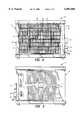
- FIG. 2is a front view of the device shown in FIG. 1;
- FIG. 3is a rear view of the device shown in FIG. 1;
- FIG. 4is a partially broken away right side view of the device shown in FIG. 1;
- FIG. 5is a left side view of the device shown in FIG. 1;
- FIG. 6is a schematic circuit diagram of a control system for the device shown in FIG. 1;
- FIG. 7is a perspective view of another embodiment.
- a portable, combination fan-heater device 11is operable to alter surrounding environmental conditions. Included in the device 11 is a housing 12 retaining a resistive heater element 13 and a rotatable fan blade 14 coupled to an electric motor 15. Defined by the housing 12 is an inlet opening 18 (FIG. 3) for passing air thereinto and an outlet opening 19 (FIG. 2) for discharging air therefrom. The inlet opening 18 is covered by an inlet grill 21 and the outlet opening 19 is covered by an outlet grill 22. In response to energization of the electric motor 15, the rotating fan blade 14 draws air in through the inlet opening 18, by the resistive heater element 13 and out of the discharge opening 19.
- an electrical supply power cord 25terminating with a plug 26 (FIG. 1) for insertion into a conventional power outlet socket (not shown) and a sensor assembly 28 and an electrical control circuit 31 (FIG. 4) both retained within the housing 12 and covered by a control panel 29.
- the control panelsupports a fan control knob 33, a heater control knob 34, a fan power signal lamp 36 and a heater power signal lamp 37.
- the control circuit 31is interconnected with the power supply cord 25, the sensor assembly 28, the resistive heater element 13 and the electric motor 15.
- the sensor assembly 28(FIG. 4) encompasses an inlet sensor 41 and an outlet sensor 42.
- Each of the sensors 41, 42is a conventional proximity detector that produces an output signal in response to the presence of an object located within a certain predetermined distance d.
- the inlet and outlet sensors 41, 42can be, for example, either the infrared or ultrasonic type. Such proximity sensors typically are directionally responsive and often provide a conical detection zone as depicted in FIG. 4. Thus, the inlet sensor 41 will produce an output signal in response to the presence of an object within a zone A adjacent to the inlet opening 18 and the outlet sensor 42 will produce an output signal in response to the presence of an object within a zone B adjacent to the outlet opening 19.
- the control circuit 31(FIG.
- control relay 45includes a control relay 45 having a relay winding 46 and contacts 47 operated thereby, a fan switch 47 operated by the fan knob 33 and a heater switch 48 operated by the heater knob 34.
- Operating power for the inlet and outlet detectors 41, 42is provided from the power cable 25 by lines 51.
- the relay winding 46is connected in parallel across, respectively, output signal lines 52 from the inlet detector 41 and output signal lines 53 from the outlet detector 42.
- a manually operated deactivator switch 55is connected between the inlet detector 41 and the relay winding 46.
- Connected in parallel in the control circuit 31are a series circuit consisting of the fan motor 13, the fan switch 47 and the fan power lamp 36, and a series circuit consisting of the resistive heater element 15, the heater power lamp 37 and the heater switch 48. That parallel combination is connected to the power supply cord 25 by the contacts 47 of the control relay 45.
- the plug 26Prior to use of the device 11, the plug 26 is inserted into a conventional wall outlet (not shown).
- the control knobs 33, 34then can be manipulated to establish a desired operational mode for the environmental conditioner 11.
- the knob 33In a fan only operating mode, the knob 33 is used to close the fan switch 47 and thereby energize the electric motor 15. Resultant rotation of the fan blade 14 produces discharge of air from the outlet opening 19.
- closure of the heater switch 48 with the knob 34energizes the resistive heater element 13 to provide heating of air within the housing 12 for discharge from the outlet 19.
- a combination modeis established by closing both the fan switch 47 and the heater switch 48 to energize both the electric motor 15 and the resistive heater element 13. Resultant rotation of the fan blade 14 draws air in through the inlet opening 18 for discharge through the outlet opening 19 after being heated by the heater element 13 within the housing 12.
- the inlet sensor 41In response to the presence of an object within zone A, the inlet sensor 41 produces on lines 52 an output that energizes the winding 46 to open the normally closed contacts 47 and thereby interrupt and prevent further transmission of power to either the fan motor 13 or the heater element 15.
- the presence of an object in zone Bcauses the outlet detector 42 to provide on lines 53 an output that energizes the relay winding 46 to open the contacts 47. Again, that occurrence interrupts and prevents any further power transmission to the heater element 13 or the fan motor 15.
- potentially unsafe operation of the device 11is prevented by the presence of an object in either of the zones A or B.
- Such objectscan include for example, an article which could undesirably obstruct the flow of air either into the inlet opening 18 or out of the outlet opening 19.
- the detectors 41, 42 and control circuit 31also would deactivate the device 11 in response to a person such as a small child attempting to insert an object into the housing 12 through either the inlet grill 21 or the outlet grill 22. Electrical deactivation would occur similarly in the event that the device 11 is inadvertently tipped to produce blockage of the inlet 18 or outlet 19 by a supporting surface such as a floor.
- deenergization of the device 11may not be desired in response to the presence of an object in the inlet detection zone A.
- the device 11could be positioned with the inlet opening 18 closely adjacent to an object such as a wall or the like but not near enough to prevent an adequate supply of air from entering the inlet 18.
- the deactivator switch 55can be manually opened to deactivate the inlet detector 41 and thereby prevent energization thereby of the relay winding 46. Desired transmission of power between the supply 25 and either one or both of the heater element 13 and the electric motor 15 then is possible through the closed contacts 47 and, respectively, the heater switch 48 and the fan switch 47.
- a portable electrical radiant heater 61which includes a portable housing 62 supported by a pair of legs 63, 64.
- Forming the housing 62are a bottom wall 66, a pair of sidewalls 67, 68, an outlet 69 covered by a front grill wall 70, a top wall 71, and a rear wall 72.
- Also formed by the housing 62is a cavity 76 defined by the bottom wall 66, the sidewalls 67, 68, the top wall 71, and the front grill wall 70.
- a pair of vertically spaced apart, elongated and horizontally oriented quartz heater elements 81, 82Located within the cavity 76 closely adjacent to the rear wall 72 are a pair of vertically spaced apart, elongated and horizontally oriented quartz heater elements 81, 82. Opposite ends of the heater elements 81, 82, are supported by the sidewalls 67, 68.
- a housing 88is supported by the top wall 71 and retains in a box 85 a control circuit 89 including signal lamps 90 and a pair of actuator switch knobs 91, 92.
- a proximity sensor unit 94for detecting the presence of any object 95 in a predetermined zone C adjacent to outlet 69.
- Forming the sensor unit 94is a conventional ultrasonic emitter 96 and a conventional ultrasonic detector 97.
- the emitter 96directs ultrasonic energy into the zone C and the detector 97 detects ultrasonic energy reflected by objects 95 in the zone C.
- Power for operating the heater elements 81, 83, and the control circuit 89is provided by a power cord with an electrical plug 93.
- the plug 93Prior to use of the device 61, the plug 93 is inserted into a conventional wall outlet (not shown).
- the control knobs 91, 92then can be manipulated to establish a desired operational mode for the environmental conditioner 61. Operation of the knob 91 is used to energize either one or both of the heater elements 81, 82 producing transmission of radiant energy into the zone C. Also, ultrasonic waves are directed into the zone C by the emitter 96. Thermostatic control of temperature is established by operation of the knob 92.
- the detector 97In response to the presence of an object 95 within zone C, the detector 97 produces an output to interrupt transmission of power to either of the heater elements 81, 82 in the manner described above for embodiment 11.
- potentially unsafe operation of the device 61is prevented by the presence of an object in the zone C.
- objectscan include for example, an article which could undesirably obstruct the flow radiant energy out of the outlet opening 69.
- the detector 97 and control circuit 89also would deactivate the device 61 in response to a person such as a small child attempting to insert an object into the housing 62 through the outlet grill 70. Electrical deactivation would occur similarly in the event that the device 61 is inadvertently tipped to produce blockage of the outlet 69 by a supporting surface such as a floor.
Landscapes
- Engineering & Computer Science (AREA)
- Physics & Mathematics (AREA)
- Thermal Sciences (AREA)
- Chemical & Material Sciences (AREA)
- Combustion & Propulsion (AREA)
- Mechanical Engineering (AREA)
- General Engineering & Computer Science (AREA)
- Direct Air Heating By Heater Or Combustion Gas (AREA)
- Air Conditioning Control Device (AREA)
Abstract
Description
Claims (19)
Priority Applications (2)
| Application Number | Priority Date | Filing Date | Title |
|---|---|---|---|
| US08/779,298US6091888A (en) | 1995-05-15 | 1997-01-06 | Portable environmental conditioning device with presence detector responsive shutoff |
| EP98300041AEP0852322A3 (en) | 1997-01-06 | 1998-01-06 | Portable environmental conditioning device with presence detector responsive shutoff |
Applications Claiming Priority (2)
| Application Number | Priority Date | Filing Date | Title |
|---|---|---|---|
| US44134695A | 1995-05-15 | 1995-05-15 | |
| US08/779,298US6091888A (en) | 1995-05-15 | 1997-01-06 | Portable environmental conditioning device with presence detector responsive shutoff |
Related Parent Applications (1)
| Application Number | Title | Priority Date | Filing Date |
|---|---|---|---|
| US44134695AContinuation-In-Part | 1995-05-15 | 1995-05-15 |
Publications (1)
| Publication Number | Publication Date |
|---|---|
| US6091888Atrue US6091888A (en) | 2000-07-18 |
Family
ID=25115952
Family Applications (1)
| Application Number | Title | Priority Date | Filing Date |
|---|---|---|---|
| US08/779,298Expired - Fee RelatedUS6091888A (en) | 1995-05-15 | 1997-01-06 | Portable environmental conditioning device with presence detector responsive shutoff |
Country Status (2)
| Country | Link |
|---|---|
| US (1) | US6091888A (en) |
| EP (1) | EP0852322A3 (en) |
Cited By (18)
| Publication number | Priority date | Publication date | Assignee | Title |
|---|---|---|---|---|
| US6810205B2 (en) | 2003-02-03 | 2004-10-26 | The W. B. Marvin Manufacturing Company | Space heater and light source |
| US20050105898A1 (en)* | 2003-11-19 | 2005-05-19 | Bachinski Thomas J. | Infrared heating system for patio umbrella |
| US7013080B1 (en) | 2001-08-13 | 2006-03-14 | The W. B. Marvin Manufacturing Company | Space heater with area light source |
| US20070046107A1 (en)* | 2005-08-29 | 2007-03-01 | Sunbeam Products, Inc. | Portable electrical applicance with object sensing assembly |
| US20070205891A1 (en)* | 2000-12-20 | 2007-09-06 | Spencer David F | Network enabled radiation detection systems, methods of monitoring radiation, and network enabled radiation monitoring systems |
| US20090214194A1 (en)* | 2008-02-21 | 2009-08-27 | Honor Tone, Ltd. | Outdoor heater |
| US20100329649A1 (en)* | 2009-05-07 | 2010-12-30 | Gary Joseph Potter | Infra-red heater assembly |
| US20140034631A1 (en)* | 2012-08-06 | 2014-02-06 | General Electric Company | Heater assembly for an appliance |
| USD732647S1 (en) | 2013-03-15 | 2015-06-23 | Illinois Tool Works Inc. | Air filtration device |
| USD737945S1 (en) | 2013-03-15 | 2015-09-01 | Illinois Tool Works Inc. | Filter |
| USD737946S1 (en) | 2013-03-15 | 2015-09-01 | Illinois Tool Works Inc. | Filter for an air filtration device |
| USD758558S1 (en) | 2014-03-10 | 2016-06-07 | Illinois Tool Works Inc. | Air filtration device |
| USD761946S1 (en) | 2014-09-12 | 2016-07-19 | Illinois Tool Works Inc. | Filter for an air filtration device |
| US9517428B2 (en) | 2014-09-12 | 2016-12-13 | Illinois Tool Works Inc. | Filter for a portable industrial air filtration device |
| US9700821B2 (en) | 2013-03-15 | 2017-07-11 | Illinois Tool Works Inc. | Portable industrial air filtration device |
| US20210302068A1 (en)* | 2020-03-31 | 2021-09-30 | World & Main (Cranbury) LLC | PTC Heater with Energy Save Function |
| US20210302065A1 (en)* | 2020-03-31 | 2021-09-30 | World & Main (Cranbury) LLC | Segmented PTC Heating Element Array |
| US11453973B2 (en)* | 2019-11-14 | 2022-09-27 | Haier Us Appliance Solutions, Inc. | Heater assembly for an appliance having one or more thermostats |
Citations (21)
| Publication number | Priority date | Publication date | Assignee | Title |
|---|---|---|---|---|
| US3643346A (en)* | 1969-05-29 | 1972-02-22 | Lestron International Corp | Drying apparatus |
| US4315596A (en)* | 1980-03-11 | 1982-02-16 | Innkeepers Electronics, Inc. | Energy conservation system for inns, hotels, and motels |
| JPS5749094A (en)* | 1980-09-08 | 1982-03-20 | Hitachi Ltd | Electric-fan controlling apparatus |
| FR2498439A1 (en)* | 1981-01-26 | 1982-07-30 | Detec Sa | Electrically powered optically actuated hand drier - has light beam passing below air outlet detecting presence of hands near outlet |
| DE3147085A1 (en)* | 1981-11-27 | 1983-06-09 | Bernd Dipl.-Ing. Dr. 4410 Warendorf Heiland | Device for energy saving, in particular in heated or air-conditioned rooms |
| US4485864A (en)* | 1981-01-14 | 1984-12-04 | Flair-Emsco Corporation | Occupancy responsive temperature control system |
| JPS60186630A (en)* | 1984-03-05 | 1985-09-24 | Nippon Denso Co Ltd | Hot air space heater |
| JPH02143030A (en)* | 1988-11-24 | 1990-06-01 | Matsushita Electric Works Ltd | Heater |
| JPH02197727A (en)* | 1989-01-26 | 1990-08-06 | Matsushita Electric Works Ltd | Air cleaner with hot-air blowing function |
| US5031337A (en)* | 1988-02-19 | 1991-07-16 | Sloan Valve Company | Automatic hand dryer |
| JPH0498032A (en)* | 1990-08-16 | 1992-03-30 | Matsushita Seiko Co Ltd | Automated ventilation device |
| US5111594A (en)* | 1990-03-17 | 1992-05-12 | Airdri Limited | Hand drier having a plurality of transmitters and at least one receiver located in the vicinity of the outlet |
| JPH04203846A (en)* | 1990-11-30 | 1992-07-24 | Matsushita Electric Ind Co Ltd | Heating apparatus for warm air |
| US5163234A (en)* | 1989-03-15 | 1992-11-17 | Inax Corporation | Hand drier control apparatus |
| US5278936A (en)* | 1991-12-23 | 1994-01-11 | Steve Shao | Thermostatically controlled portable electric space heater with automatic temperature setback for energy saving |
| JPH06142009A (en)* | 1992-11-12 | 1994-05-24 | Sekisui Chem Co Ltd | Heater and sanitary room with the heater |
| US5381509A (en)* | 1993-04-28 | 1995-01-10 | The W. B. Marvin Manufacturing Company | Radiant electric space heater |
| US5437001A (en)* | 1992-12-21 | 1995-07-25 | The W. B. Marvin Manufacturing Company | Upright radiant electric heating appliance |
| JPH0825943A (en)* | 1994-07-19 | 1996-01-30 | Mitsubishi Heavy Ind Ltd | Air conditioner for vehicle |
| JPH1019384A (en)* | 1996-06-28 | 1998-01-23 | Toshiba Home Technol Corp | Heat storage heater |
| US5805767A (en)* | 1996-01-16 | 1998-09-08 | Jouas; Gary | Electronically-controlled heater |
Family Cites Families (2)
| Publication number | Priority date | Publication date | Assignee | Title |
|---|---|---|---|---|
| GB8917745D0 (en)* | 1989-08-03 | 1989-09-20 | I O Innovation Design Consulta | Fan-controlled ptc heating apparatus |
| FR2728062A1 (en)* | 1994-12-09 | 1996-06-14 | Sgs Thomson Microelectronics | HEATING SYSTEM COMPRISING A CONTROL UNIT AND RADIATORS PROVIDED WITH PRESENCE DETECTION MEANS |
- 1997
- 1997-01-06USUS08/779,298patent/US6091888A/ennot_activeExpired - Fee Related
- 1998
- 1998-01-06EPEP98300041Apatent/EP0852322A3/ennot_activeWithdrawn
Patent Citations (21)
| Publication number | Priority date | Publication date | Assignee | Title |
|---|---|---|---|---|
| US3643346A (en)* | 1969-05-29 | 1972-02-22 | Lestron International Corp | Drying apparatus |
| US4315596A (en)* | 1980-03-11 | 1982-02-16 | Innkeepers Electronics, Inc. | Energy conservation system for inns, hotels, and motels |
| JPS5749094A (en)* | 1980-09-08 | 1982-03-20 | Hitachi Ltd | Electric-fan controlling apparatus |
| US4485864A (en)* | 1981-01-14 | 1984-12-04 | Flair-Emsco Corporation | Occupancy responsive temperature control system |
| FR2498439A1 (en)* | 1981-01-26 | 1982-07-30 | Detec Sa | Electrically powered optically actuated hand drier - has light beam passing below air outlet detecting presence of hands near outlet |
| DE3147085A1 (en)* | 1981-11-27 | 1983-06-09 | Bernd Dipl.-Ing. Dr. 4410 Warendorf Heiland | Device for energy saving, in particular in heated or air-conditioned rooms |
| JPS60186630A (en)* | 1984-03-05 | 1985-09-24 | Nippon Denso Co Ltd | Hot air space heater |
| US5031337A (en)* | 1988-02-19 | 1991-07-16 | Sloan Valve Company | Automatic hand dryer |
| JPH02143030A (en)* | 1988-11-24 | 1990-06-01 | Matsushita Electric Works Ltd | Heater |
| JPH02197727A (en)* | 1989-01-26 | 1990-08-06 | Matsushita Electric Works Ltd | Air cleaner with hot-air blowing function |
| US5163234A (en)* | 1989-03-15 | 1992-11-17 | Inax Corporation | Hand drier control apparatus |
| US5111594A (en)* | 1990-03-17 | 1992-05-12 | Airdri Limited | Hand drier having a plurality of transmitters and at least one receiver located in the vicinity of the outlet |
| JPH0498032A (en)* | 1990-08-16 | 1992-03-30 | Matsushita Seiko Co Ltd | Automated ventilation device |
| JPH04203846A (en)* | 1990-11-30 | 1992-07-24 | Matsushita Electric Ind Co Ltd | Heating apparatus for warm air |
| US5278936A (en)* | 1991-12-23 | 1994-01-11 | Steve Shao | Thermostatically controlled portable electric space heater with automatic temperature setback for energy saving |
| JPH06142009A (en)* | 1992-11-12 | 1994-05-24 | Sekisui Chem Co Ltd | Heater and sanitary room with the heater |
| US5437001A (en)* | 1992-12-21 | 1995-07-25 | The W. B. Marvin Manufacturing Company | Upright radiant electric heating appliance |
| US5381509A (en)* | 1993-04-28 | 1995-01-10 | The W. B. Marvin Manufacturing Company | Radiant electric space heater |
| JPH0825943A (en)* | 1994-07-19 | 1996-01-30 | Mitsubishi Heavy Ind Ltd | Air conditioner for vehicle |
| US5805767A (en)* | 1996-01-16 | 1998-09-08 | Jouas; Gary | Electronically-controlled heater |
| JPH1019384A (en)* | 1996-06-28 | 1998-01-23 | Toshiba Home Technol Corp | Heat storage heater |
Cited By (34)
| Publication number | Priority date | Publication date | Assignee | Title |
|---|---|---|---|---|
| US20070205891A1 (en)* | 2000-12-20 | 2007-09-06 | Spencer David F | Network enabled radiation detection systems, methods of monitoring radiation, and network enabled radiation monitoring systems |
| US7013080B1 (en) | 2001-08-13 | 2006-03-14 | The W. B. Marvin Manufacturing Company | Space heater with area light source |
| US6810205B2 (en) | 2003-02-03 | 2004-10-26 | The W. B. Marvin Manufacturing Company | Space heater and light source |
| US20050105898A1 (en)* | 2003-11-19 | 2005-05-19 | Bachinski Thomas J. | Infrared heating system for patio umbrella |
| US7003217B2 (en)* | 2003-11-19 | 2006-02-21 | Hon Technology Inc. | Infrared heating system for patio umbrella |
| US7573158B2 (en) | 2005-08-29 | 2009-08-11 | Sunbeam Products, Inc. | Portable electrical appliance with object sensing assembly |
| US20070046107A1 (en)* | 2005-08-29 | 2007-03-01 | Sunbeam Products, Inc. | Portable electrical applicance with object sensing assembly |
| US20090214194A1 (en)* | 2008-02-21 | 2009-08-27 | Honor Tone, Ltd. | Outdoor heater |
| US7974526B2 (en)* | 2008-02-21 | 2011-07-05 | Honor Tone, Ltd. | Outdoor heater |
| US20100329649A1 (en)* | 2009-05-07 | 2010-12-30 | Gary Joseph Potter | Infra-red heater assembly |
| US8693855B2 (en)* | 2009-05-07 | 2014-04-08 | Cambridge Engineering, Inc | Infra-red heater assembly |
| US20140034631A1 (en)* | 2012-08-06 | 2014-02-06 | General Electric Company | Heater assembly for an appliance |
| US9869053B2 (en)* | 2012-08-06 | 2018-01-16 | Haier Us Appliance Solutions, Inc. | Heater assembly for an appliance |
| USD744624S1 (en) | 2013-03-15 | 2015-12-01 | Illinois Tool Works, Inc. | Filter for an air filtration device |
| USD732647S1 (en) | 2013-03-15 | 2015-06-23 | Illinois Tool Works Inc. | Air filtration device |
| USD744626S1 (en) | 2013-03-15 | 2015-12-01 | Illinois Tool Works, Inc. | Filter for an air filtration device |
| USD737945S1 (en) | 2013-03-15 | 2015-09-01 | Illinois Tool Works Inc. | Filter |
| USD744625S1 (en) | 2013-03-15 | 2015-12-01 | Illinois Tool Works, Inc. | Filter for an air filtration device |
| USD746969S1 (en) | 2013-03-15 | 2016-01-05 | Illinois Tool Works Inc. | Filter for an air filtration device |
| USD752728S1 (en) | 2013-03-15 | 2016-03-29 | Illinois Tool Works Inc. | Air filtration device |
| USD737946S1 (en) | 2013-03-15 | 2015-09-01 | Illinois Tool Works Inc. | Filter for an air filtration device |
| US9776117B2 (en) | 2013-03-15 | 2017-10-03 | Illinois Tool Works Inc. | Portable industrial air filtration device |
| USD797273S1 (en) | 2013-03-15 | 2017-09-12 | Illinois Tool Works Inc. | Air filtration device filter pin |
| US9700821B2 (en) | 2013-03-15 | 2017-07-11 | Illinois Tool Works Inc. | Portable industrial air filtration device |
| USD785775S1 (en) | 2013-03-15 | 2017-05-02 | Illinois Tool Works Inc. | Cover for an air filtration device |
| USD785153S1 (en) | 2014-03-10 | 2017-04-25 | Illinois Tool Works Inc. | Air filtration device |
| USD785154S1 (en) | 2014-03-10 | 2017-04-25 | Illinois Tool Works Inc. | Air filtration device |
| USD758558S1 (en) | 2014-03-10 | 2016-06-07 | Illinois Tool Works Inc. | Air filtration device |
| US9517428B2 (en) | 2014-09-12 | 2016-12-13 | Illinois Tool Works Inc. | Filter for a portable industrial air filtration device |
| USD761946S1 (en) | 2014-09-12 | 2016-07-19 | Illinois Tool Works Inc. | Filter for an air filtration device |
| US10226729B2 (en) | 2014-09-12 | 2019-03-12 | Illinois Tool Works Inc. | Filter for a portable industrial air filtration device |
| US11453973B2 (en)* | 2019-11-14 | 2022-09-27 | Haier Us Appliance Solutions, Inc. | Heater assembly for an appliance having one or more thermostats |
| US20210302068A1 (en)* | 2020-03-31 | 2021-09-30 | World & Main (Cranbury) LLC | PTC Heater with Energy Save Function |
| US20210302065A1 (en)* | 2020-03-31 | 2021-09-30 | World & Main (Cranbury) LLC | Segmented PTC Heating Element Array |
Also Published As
| Publication number | Publication date |
|---|---|
| EP0852322A3 (en) | 2000-02-23 |
| EP0852322A2 (en) | 1998-07-08 |
Similar Documents
| Publication | Publication Date | Title |
|---|---|---|
| US6091888A (en) | Portable environmental conditioning device with presence detector responsive shutoff | |
| US5652826A (en) | Radiant electric space heater with capillary tube thermostat | |
| US5805767A (en) | Electronically-controlled heater | |
| US4110600A (en) | Thermostatically controlled plural heat output portable electric space heater | |
| US5139009A (en) | Exhaust ventilation control system | |
| CA1232249A (en) | Multi-purpose fan | |
| KR940009071B1 (en) | Fan heater controller | |
| EP0417309B1 (en) | Fan heater controller | |
| US7573158B2 (en) | Portable electrical appliance with object sensing assembly | |
| US4926837A (en) | Cooking ovens | |
| US4831225A (en) | Microwave oven/convection oven having means for controlling ventilation of the cooking chamber | |
| US6603102B2 (en) | Pressure monitoring arrangement for heating system of a convection cooking appliance | |
| US5838878A (en) | Portable quartz heater | |
| US6169850B1 (en) | Air heating device | |
| CA2174812A1 (en) | Portable environmental conditioning device with presence detector responsive shutoff | |
| KR200334441Y1 (en) | Multi-Purpose Air-Blower | |
| JPS61195229A (en) | Air conditioner | |
| KR940003236Y1 (en) | Safety device of fan heater | |
| KR100351941B1 (en) | A controlling method of cavity temperature in microwave oven | |
| JP2662086B2 (en) | Electric heating cooker abnormality detection device | |
| GB2144843A (en) | Multi-mode fan heater | |
| JP3033426U (en) | Gas fan heater | |
| JP2998381B2 (en) | Toilet equipment | |
| JPH04371754A (en) | Air conditioner | |
| JP3170846B2 (en) | Heating system |
Legal Events
| Date | Code | Title | Description |
|---|---|---|---|
| AS | Assignment | Owner name:DURACRAFT CORPORATION, MASSACHUSETTS Free format text:ASSIGNMENT OF ASSIGNORS INTEREST;ASSIGNORS:JANE, RODNEY B.;LONGAN, JOHN;WANG, JUI-SHANG;REEL/FRAME:008420/0663;SIGNING DATES FROM 19970207 TO 19970220 | |
| AS | Assignment | Owner name:HONEYWELL CONSUMER PRODUCTS, INC., MASSACHUSETTS Free format text:CHANGE OF NAME;ASSIGNORS:JANE, RODNEY B.;LONGAN, JOHN;WANG, JUI-SHANG;AND OTHERS;REEL/FRAME:008867/0498;SIGNING DATES FROM 19970118 TO 19970207 | |
| AS | Assignment | Owner name:HONEYWELL CONSUMER PRODUCTS, INC., MASSACHUSETTS Free format text:CHANGE OF NAME;ASSIGNOR:DURACRAFT CORPORATION;REEL/FRAME:008854/0440 Effective date:19961121 | |
| AS | Assignment | Owner name:KAZ HOME ENVIRONMENT, INC., MASSACHUSETTS Free format text:CHANGE OF NAME;ASSIGNOR:HONEYWELL CONSUMER PRODUCTS, INC.;REEL/FRAME:013897/0758 Effective date:20020827 Owner name:KAZ, INC., NEW YORK Free format text:ASSIGNMENT OF ASSIGNORS INTEREST;ASSIGNOR:KAZ HOME ENVIRONMENT, INC.;REEL/FRAME:013868/0187 Effective date:20030328 | |
| REMI | Maintenance fee reminder mailed | ||
| FPAY | Fee payment | Year of fee payment:4 | |
| SULP | Surcharge for late payment | ||
| AS | Assignment | Owner name:BANK OF AMERICA, N.A., AS AGENT, MASSACHUSETTS Free format text:SECURITY AGREEMENT;ASSIGNORS:KAZ, INC.;KAZ USA, INC.;KAZ CANADA, INC.;REEL/FRAME:017215/0696 Effective date:20060131 | |
| REMI | Maintenance fee reminder mailed | ||
| LAPS | Lapse for failure to pay maintenance fees | ||
| STCH | Information on status: patent discontinuation | Free format text:PATENT EXPIRED DUE TO NONPAYMENT OF MAINTENANCE FEES UNDER 37 CFR 1.362 | |
| FP | Lapsed due to failure to pay maintenance fee | Effective date:20080718 |