US6091832A - Wearable personal audio loop apparatus - Google Patents
Wearable personal audio loop apparatusDownload PDFInfo
- Publication number
- US6091832A US6091832AUS08/909,402US90940297AUS6091832AUS 6091832 AUS6091832 AUS 6091832AUS 90940297 AUS90940297 AUS 90940297AUS 6091832 AUS6091832 AUS 6091832A
- Authority
- US
- United States
- Prior art keywords
- audio
- loop member
- individual
- wearable personal
- audio apparatus
- Prior art date
- Legal status (The legal status is an assumption and is not a legal conclusion. Google has not performed a legal analysis and makes no representation as to the accuracy of the status listed.)
- Expired - Lifetime
Links
- 230000006854communicationEffects0.000claimsabstractdescription49
- 238000004891communicationMethods0.000claimsabstractdescription48
- 210000003128headAnatomy0.000claimsabstractdescription39
- 210000001061foreheadAnatomy0.000claimsabstractdescription23
- 230000005236sound signalEffects0.000claimsdescription42
- 210000005069earsAnatomy0.000claimsdescription19
- 230000007246mechanismEffects0.000claimsdescription16
- 230000013011matingEffects0.000claimsdescription7
- 230000004044responseEffects0.000claimsdescription7
- 230000000007visual effectEffects0.000claimsdescription7
- 230000000694effectsEffects0.000claimsdescription4
- 230000001681protective effectEffects0.000abstract1
- 238000010586diagramMethods0.000description7
- 230000008901benefitEffects0.000description5
- 230000001413cellular effectEffects0.000description5
- 210000000613ear canalAnatomy0.000description4
- 238000003491arrayMethods0.000description2
- 239000011521glassSubstances0.000description2
- 239000000463materialSubstances0.000description2
- QSHDDOUJBYECFT-UHFFFAOYSA-NmercuryChemical compound[Hg]QSHDDOUJBYECFT-UHFFFAOYSA-N0.000description2
- 229910052753mercuryInorganic materials0.000description2
- 230000004048modificationEffects0.000description2
- 238000012986modificationMethods0.000description2
- 230000011664signalingEffects0.000description2
- 241000557626Corvus coraxSpecies0.000description1
- XUIMIQQOPSSXEZ-UHFFFAOYSA-NSiliconChemical compound[Si]XUIMIQQOPSSXEZ-UHFFFAOYSA-N0.000description1
- 230000003213activating effectEffects0.000description1
- 230000004913activationEffects0.000description1
- 230000008859changeEffects0.000description1
- 238000010276constructionMethods0.000description1
- 230000007812deficiencyEffects0.000description1
- 230000001627detrimental effectEffects0.000description1
- 210000004709eyebrowAnatomy0.000description1
- 230000006870functionEffects0.000description1
- 230000006872improvementEffects0.000description1
- 230000003993interactionEffects0.000description1
- 239000007788liquidSubstances0.000description1
- 239000012858resilient materialSubstances0.000description1
- 230000007727signaling mechanismEffects0.000description1
- 229910052710siliconInorganic materials0.000description1
- 239000010703siliconSubstances0.000description1
- 230000003997social interactionEffects0.000description1
- 230000000475sunscreen effectEffects0.000description1
- 239000000516sunscreening agentSubstances0.000description1
- 210000000216zygomaAnatomy0.000description1
Images


Classifications
- H—ELECTRICITY
- H04—ELECTRIC COMMUNICATION TECHNIQUE
- H04R—LOUDSPEAKERS, MICROPHONES, GRAMOPHONE PICK-UPS OR LIKE ACOUSTIC ELECTROMECHANICAL TRANSDUCERS; DEAF-AID SETS; PUBLIC ADDRESS SYSTEMS
- H04R5/00—Stereophonic arrangements
- H04R5/033—Headphones for stereophonic communication
- H04R5/0335—Earpiece support, e.g. headbands or neckrests
- G—PHYSICS
- G02—OPTICS
- G02C—SPECTACLES; SUNGLASSES OR GOGGLES INSOFAR AS THEY HAVE THE SAME FEATURES AS SPECTACLES; CONTACT LENSES
- G02C11/00—Non-optical adjuncts; Attachment thereof
- G02C11/06—Hearing aids
- G—PHYSICS
- G02—OPTICS
- G02C—SPECTACLES; SUNGLASSES OR GOGGLES INSOFAR AS THEY HAVE THE SAME FEATURES AS SPECTACLES; CONTACT LENSES
- G02C11/00—Non-optical adjuncts; Attachment thereof
- G02C11/10—Electronic devices other than hearing aids
- H—ELECTRICITY
- H04—ELECTRIC COMMUNICATION TECHNIQUE
- H04R—LOUDSPEAKERS, MICROPHONES, GRAMOPHONE PICK-UPS OR LIKE ACOUSTIC ELECTROMECHANICAL TRANSDUCERS; DEAF-AID SETS; PUBLIC ADDRESS SYSTEMS
- H04R2420/00—Details of connection covered by H04R, not provided for in its groups
- H04R2420/07—Applications of wireless loudspeakers or wireless microphones
Definitions
- the present inventionrelates to wearable personal audio systems.
- Portable, personal communications systemssuch as cellular telephones and cordless telephones, are currently experiencing a dramatic growth in utilization.
- Cellular telephonesfor example, have enabled users to transcend the constraints of fixed telephony by allowing communication outside of buildings.
- societywill probably witness a significant wireless evolution in both personal and professional communications which will change the way people conduct their lives at home, on the road, and at work.
- Audio signalscan be generated by numerous systems including FM and AM radio, TV, cassette tape players, CD and mini-CD players, MD players and players/recorders, DAT players and players/recorders, CB radios, walkie-talkies, radio scanners and the like.
- the audiois typically generated by a hand-held or wearable system combined with one or more devices used to convey the sound signals directly to the wearer's ears, such as earphones, headphones, earbuds, etc.
- These systemstypically only convey audio signals to the wearer, do not allow the user to communicate inter-parties with others, and are not versatile or adaptable for multi-system usage.
- Some of these personal communication systemsinclude a transmitter-receiver pair along with an audio output and an audio input device.
- the audio output devicetypically comprises a speaker, headphones, earphones, or the like.
- audio output devices for use with a personal communication systemare devices capable of producing sound waves representative of an electronic audio signal applied thereto, and are employed in contact with or adjacent to the ear of the user.
- the audio input devicetypically comprises a microphone or a like transducer. The audio input device produces an electronic signal representative of sound waves received thereby.
- the audio input and output devicesare incorporated on a handset, such as a portable cellular telephone.
- a handsetsuch as a portable cellular telephone.
- This arrangementis disadvantageous in that a hand of the user becomes occupied during the communication process.
- the user of a handsetis limited in the types of activities he/she can perform while simultaneously communicating.
- the audio signalsalso are monorial, not stereophonic, and typically only provided to one of the user's ears.
- either headphones or earphonesmay be employed.
- a microphonecan be located on a headset, such as worn by telephone operators and receptionists.
- a headsetsuch as worn by telephone operators and receptionists.
- Such an arrangementis also socially disadvantageous when attempting to interact with others in his/her physical space. Further, the use of a headset is conspicuous in public use.
- U.S. Pat. No. 4,888,805 to Karppala, Jr.describes a stereo headphone bracket system using socket receivers mounted on each transducer of a pair of stereo headphones and each of two respective eyeglass temples.
- a piece of semi-rigid wire having on each end a plug matable with a respective socket receiveris used to join the socket receiver on a transducer to the socket receiver on the respective eyeglass temple.
- U.S. Pat. No. 5,164,987 to Ravendescribes a personal stereo speaker assembly adapted to be supported by temple pieces of eyeglasses using a pair of sleeves which receive the temple pieces therein. Secured to each sleeve is an envelope adapted to enclose and support respective standard miniature speakers. The miniature speakers are located approximately at the ear openings of a user.
- U.S. Pat. No. 5,272,757 to Scofield et al.discloses a multi-dimensional sound reproduction system having localized speakers supported on a pair of glasses.
- the speakersare supported in housings disposed on opposite sides of the glasses.
- Each speakeris located proximate to a respective side of the head of the user in the area of the zygomatic arch, and is directed rearward toward a respective pinna of the user.
- U.S. Pat. No. 4,819,270 to Lombardodescribes a stereo dimensional recording apparatus utilizing a pair of microphones which can be mounted to separate pieces of eyewear apparel, headwear apparel, and head band accessories.
- Still another object of the present inventionis to provide a wearable personal audio apparatus which can be selectively configured to form either a pair of headphones or a pair of eyeglasses, or both.
- a further object of the present inventionis to provide a wearable personal audio apparatus which is socially acceptable and/or inconspicuous to others.
- the present inventionprovides a wearable personal audio communication apparatus for use with an audio circuit.
- the circuitcan be positioned in the apparatus itself, separately on the body, or at a base station at the same site or in the same area, and communicate with the wearable apparatus by wire or a wireless communication system.
- the wearable personal audio apparatuspreferably includes a wearable generally U-shaped or C-shaped audio loop member adapted to fit an individual in a plurality of different positions on the individual's body.
- the loop membercan be positioned at virtually any position along the front, top and back of the head.
- the loop membercan be positioned on the front or back of the wearer's neck.
- the loop memberWhen positioned on the neck, the loop member could be included within or covered by a wearable garment or the like, if desired. When worn on the head, a sunglass or corrective eyeglass lens could be attached to the loop member so the apparatus could have a real or pseudo secondary use.
- the loop membercan include a slot or other eyewear-receiving member for removably receiving the eyewear insert.
- the U- or C-shaped memberpreferably is flexible and conformable so that it can be adapted to be positioned at any of these locations and be comfortable to the wearer.
- the loop memberalso could be sufficiently flexible in order to be folded or rolled-up for storage.
- the loop memberWhen used as a pair of eyeglasses or sunglasses, the loop member preferably has a pair of earpieces or temple members hinged to a front or frame section. When the eyewear insert member is removed, the loop member can be worn as a single C-shaped or U-shaped member.
- the loop membercontains a plurality of audio input and audio output devices which are appropriately positioned--and can be provided in duplicate sets--in order to provide the requisite audio output to the wearer and receive the audio input from the wearer.
- the audio devicescan be permanently embedded in or be provided as a permanent part of the loop member.
- a plurality of quick-connect interface portscan be positioned around the loop member to selectively receive a plurality of external audio transducer "plug-in" modules.
- the audio transducer modulescan include audio output devices which produce an acoustic pressure wave in response to an audio signal provided by the audio circuit, or audio input devices which produce an audio signal representative of an acoustic pressure wave received thereby for communication to the audio circuit.
- a first plurality of quick-connect interface portsis designated for receiving audio output device modules and a second plurality of quick connect interface ports is designated for receiving audio input device modules.
- the quick-connect interface portsprovide a respective communication path between each of the external audio transducers and the audio circuit.
- the quick-connect interface portsare preferably located within each of the two earpieces and positioned adjacent the wearer's ears. These ports are adapted to receive a pair of audio output devices (i.e. transducers or speakers).
- the pair of audio output devicesare proximate to the individual's ears when the loop member is positioned at any of the various locations on the head of the wearer, such as across the forehead, at the hairline, anywhere on the top of the head, at the back of the head, etc.
- the wearable personal audio apparatusprovides a headphone for the user, and can be utilized with or without an eyeglass or sunglass insert member.
- the loop membercan be worn openly similar to a necklace or a piece of jewelry, or can be hidden from view, such as being positioned inside the collar of the wearer's garment, under a scarf, or the like.
- audio input and output devices or quick-connect portsare provided at various appropriate positions on the loop member.
- audio output devices or portsare provided on the two opposed side portions or earpieces of the loop member, either in the mid-portion or at the ends thereof, so they will be positioned adjacent the wearer's ears regardless of the position in which the loop member is worn.
- audio input devices or portsare positioned at or adjacent to the two ends of the loop member so they will be positioned as close as possible to the wearer's mouth when the loop member is positioned on the back of the head or neck of the wearer.
- a switching deviceis preferably provided in order for the wearer to select the appropriate audio input and output devices to be activated, depending on the manner and position that the loop member is worn.
- the switching device or mechanismis preferably positioned on the loop member.
- a visible or audible signalling devicecan be provided on the loop member in order to notify others that the personal communication system in the loop member is in use.
- the audio signals to and from the loop member, or between the different or spaced apart audio devices in the loop member,can be provided through direct wires or a wireless system.
- the electronics for the loop membercan be provided in a module positioned at another location on the wearer's body, such as in a pocket or on a belt, or positioned in the same room or area.
- each audio input or output device modulecan consist of two or more transducers (speakers or microphones).
- two or more audio input or output devicescan be provided at each location or quick-connect port on the loop member.
- the loop memberincludes a loop receiving member for mounting thereto a similar or "like" loop member from a like wearable personal audio apparatus.
- an interface portis included to connect to a mating interface port of the like wearable personal audio apparatus when the like loop member is mounted in the loop receiving member.
- the interface port and the mating interface portprovide a communication path between the audio circuit and an audio transducer of the two wearable personal audio devices.
- a pair of loop memberscould be provided which are pivotably or rotatably connected together.
- One of the loop memberscan contain the audio input devices and the other of the loop members can contain the audio output devices.
- the two loopscan be situated in a first position next to each other and hidden from view in the collar or garment of the wearer, or be hinged apart in a second position with the audio input devices adjacent the wearer's mouth and the audio output devices positioned adjacent the wearer's ears.
- two separate loop membersto be provided, one with audio input devices and one with audio output devices, and for the two loop members to be positioned separately at different locations on the wearer's head and neck.
- the present inventioncould be utilized as a pair of headphones or the like and plugged into an audio or communication device or system, such as a cellular telephone, TV, AM or FM radio, cassette deck, CD-ROM, or the like.
- an audio or communication device or systemsuch as a cellular telephone, TV, AM or FM radio, cassette deck, CD-ROM, or the like.
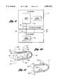
- FIG. 1is a block diagram of an embodiment of a wearable personal audio apparatus in accordance with the present invention
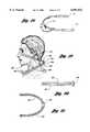
- FIG. 2is an illustration of an embodiment of the wearable personal audio apparatus worn across the forehead of an individual
- FIG. 3is an illustration of an embodiment of the wearable personal audio apparatus worn around the back of the neck of the individual
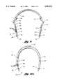
- FIG. 4is an illustration of an embodiment of the wearable personal audio apparatus worn around the top of the head of the individual
- FIG. 5is a bottom view of an embodiment of the wearable personal audio apparatus depicting the quick-connect ports
- FIG. 6depicts a one-piece loop member in accordance with the present invention
- FIG. 7is a block diagram of an alternative embodiment of the wearable personal audio apparatus.
- FIGS. 8 and 8Aillustrate additional alternative embodiments of the invention
- FIG. 9is a block diagram of an embodiment which allows multiple loop members to be stacked.
- FIG. 10illustrates an embodiment of the invention with selectively positionable audio input and output devices
- FIG. 11illustrates an embodiment of the invention with pairs of transducers forming each of the audio input and output devices
- FIGS. 12-15depict various alternative electronic systems for use with the present invention.
- FIG. 16is a schematic diagram of a representative circuit for use with the present invention.
- FIG. 17is a schematic illustration showing use of the present invention with alternative electronic systems
- FIG. 18illustrates a visual signalling mechanism for use with the present invention.
- FIGS. 19-21illustrate alternate embodiments of the invention utilizing two loop members.
- the audio apparatusis preferably provided in the form of a U-shaped or C-shaped structure.
- the loop memberin accordance with the preferred embodiments of the present invention: a unitary one-piece loop member; and a three-piece loop member with a front or frame section hingedly attached to a pair of side or earpieces. It is understood, of course, that other shapes and forms of the invention could also be utilized.
- FIG. 1there is shown a schematic block diagram of one embodiment of a wearable personal audio apparatus in accordance with the present invention.
- the apparatusincludes a wearable, U-shaped or C-shaped loop member 25 (as better shown in FIGS. 3 and 4) adapted to f it an individual in any of a plurality of positions on the individual's body.
- the plurality of positionsincludes a position across the forehead of an individual 30 as illustrated in FIG. 2, another position around the back of the neck of the individual as illustrated in FIG. 3, and a further position around the top of the head of the individual as illustrated in FIG. 4.
- the apparatuscan be positioned at numerous other positions on the wearer's head, neck or other body members, such as at the hairline, on the back of the head, on the front of the neck (like a necklace), etc.
- the wearable loop member 25generally includes an eyewear receiving member 32 which can be adapted to removably receive an eyewear insert member 34.
- the member 34can be a corrective lens, a sunglass, a sunscreen, or the like to provide a form of eyewear for the individual.
- the loop membercan be worn as a regular pair of eyeglasses or sunglasses, as depicted in FIG. 2, or can be positioned on the head, neck, or torso of the individual in any of the other positions where eyeglasses and sunglasses are positioned, transported or worn by individuals today.
- the apparatusfurther includes a plurality of quick-connect interface ports 36 disposed around the loop member 25.
- the quick-connect interface ports 36selectively receive a plurality of external audio transducer modules 38. It is not required for all of the quick-connect interface ports 36 to receive a respective one of the external audio transducer modules 38.
- the quick-connect interface ports indicated by reference numeral 40are utilized to receive the external audio transducer modules 38, while the quick-connect interface ports indicated by reference numeral 42 are not coupled to an external audio transducer module.
- the quick-connect interface ports 36are utilized to provide a respective communication path between each of the external audio transducer modules 38 and an audio circuit 44.
- the audio circuit 44can be positioned in many locations. It can be contained within the wearable U-shaped loop member 25, as illustrated in FIG. 1. Alternatively, the audio circuit can be located external to the loop member 25 and positioned at other locations on the wearer's body, such as at the waist, in a pocket, on a belt, or at an external site not on the wearer's body, such as on a vehicle, carrying device, or the like.
- the audio circuit 44is typically powered by a battery 46 which can be of any conventional type, but preferably is an exchangeable plug-in or snap-in battery or set of batteries.
- the external audio transducer modules 38can include an audio output device, such as a speaker, which produces an acoustic pressure wave in response to an audio signal provided by the audio circuit 44.
- the external audio transducer modules 38may also include an audio input device, such as a microphone, which produces an audio signal representative of an acoustic pressure wave received thereby.
- the audio signalis communicated to the audio circuit 44 via one of the quick-connect interface ports 36. It is preferred that a first plurality of the quick-connect interface ports be designated only for receiving audio output device modules and a second plurality of the quick-connect interface ports be designated only for receiving audio input device modules.
- a wearable U-shaped loop memberincludes an eyewear receiving member or slot 52 for selectively receiving an eyewear insert.
- the eyewear receiving member 52defines a single lens-receiving slot 54 for receiving an eyewear insert in the form of a single lens or a single pane (as shown, for example, in FIG. 2).
- the eyewear receiving member 52is disposed on an arcuate front or frame portion 56 of the loop member 50.
- a pair of side support members 58 and 60are jointed to the arcuate member 56 to form the U-shape of the loop member 50.
- the side support member 58includes a receiving hole 62 which receives a hinge pin 64 of the arcuate member 56.
- the side support member 60defines a receiving hole 66 which receives a hinge pin 68 of the arcuate member 56.
- the pin receiving holes 62 and 66cooperate with the hinge pins 64 and 68 to form hinges for jointing the side support members 58 and 60 to the arcuate member 56.
- the side support member 58includes an earpiece 70
- the side support member 60includes an earpiece 72.
- the two earpieces 70 and 72are adapted to rest on the ears of the individual when the loop member is worn around the forehead (as shown in FIG. 2).
- the individualis generally indicated by the reference numeral 30 and is wearing the loop member around his forehead 31.
- the two earpieces 70 and 72rest upon upper portions of the individual's ears 71 and 73.
- each of the quick-connect interface ports 82includes two receiving holes for receiving two external pins 84 and 86 of a representative external audio transducer plug-in module 88.
- the external audio transducer module 88can include either an audio output device (i.e. a speaker) or an audio input device (i.e. a microphone).
- quick-connect interface ports indicated by reference numerals 90, 92, 94, 96, 98, and 100are designated for receiving audio output device modules.
- the remaining quick-connect interface ports indicated by reference numerals 102 and 104are designated for receiving audio input device modules (microphones).
- the quick-connect interface portsare located near or at the ends 106 and 108 of the earpieces 70 and 72.
- the ports 102 and 104are positioned on the earpieces 70 and 72 so that when the loop member is worn around the back of the neck of the individual, such as shown in FIG. 3, the quick-connect interface ports 102 and 104 are located on generally opposite sides of the neck and are proximate to the individual's collarbone. In this manner, microphones positioned in the ports 102 and 104 will be situated close to the mouth of the wearer.
- FIG. 3When the loop member is worn in the position shown in FIG. 3, another pair of the quick-connect interface ports, indicated by reference numerals 90 and 92, are located on the side support members 58 and 60. These ports are designated for receiving audio output device modules (speakers).
- interface ports 90 and 92 with speakers thereinare located on generally opposite sides of the individual's neck close to the wearer's ears.
- a pair of audio input devices 110 and 111are plugged into the quick-connect interface ports 102 and 104, respectively, and a pair of audio output device modules 114 and 115 are plugged into the quick-connect interface ports 90 and 92, respectively.
- the placement of the audio input device (microphone) modules 110 and 111 on either side of the individual's collarboneprovides for a continuous, spatially correct capture of the stereo image of the individual's speech, and more generally, the sounds which are produced in the wearer's physical space.
- the audio output device (speaker) modules 114 and 115are located on generally opposite sides of the individual's neck and are positioned rearwardly from the individual's collarbone. The use of the pair of audio output device modules on either side of the neck provides a capability for producing a spatialized stereo audio environment for the individual.
- the quick-connect interface ports indicated by reference numerals 98 and 100are located on inner portions of the two earpieces 70 and 72.
- the ports 98 and 100are adapted to receive a pair of audio output device modules when the loop member is worn around the top of the head of the individual. This is illustrated in FIG. 4, wherein an individual 30 is shown wearing the loop member 50 around the top of his head 33.
- the arcuate center section 56 of the loop member 50is positioned on the top of the head and the side support members 58 and 60 deform sufficiently to fit around the individual's head.
- the side support members and the arcuate center memberbe formed from a resilient material, such as plastic--although the final choice of materials should be left to the designers.
- the earpieces 70 and 72When worn in the manner shown in FIG. 4, the earpieces 70 and 72 extend approximately to the center of the ear canals of the individual.
- the side support members and/or earpiecescan have adjustment mechanisms incorporated therein so that the axial longitudinal length of the side support members can be changed in order to fit the wearer. Any of the known adjustment mechanisms for adjusting the length of eyeglass temples could be utilized.
- the quick-connect interface ports 98 and 100have a pair of audio output device modules (speakers) 118 and 119 positioned in them.
- the modules 118 and 119are located proximate to the individual's ears, and more specifically, proximate to the ear canals of the individual when the loop member is worn around the head.
- a headphone-like configurationcan be provided using embodiments of the present invention.
- the loop member 120is provided as a single unitary C-shaped or U-shaped structure. This is shown in FIG. 6.
- the member 120is flexible and conformable so that it can be adapted to be comfortably positioned at any location on the head or neck of the wearer.
- the loop member 120has a relatively small cross-sectional size, on the order of 1/8 to 1/2 inches on a side.
- the cross-section of the loop member in accordance with any of the embodiments of the inventioncan have any configuration, such as round, elliptical, square, kidney-shaped, or the like.
- the one-piece loop member 120(FIG. 6) preferably has a plurality of quick-connect ports 122 of the same type and purpose as those described above with reference to FIGS. 3, 4 and 5. These ports allow placement of portable replaceable audio input and audio output devices as desired by the wearer.
- audio output devices(speakers) 124 and 125 are shown, as well as audio input devices (microphones) 128 and 129.
- the loop memberFor ease of transporting and storing the loop members of the present invention, it is also possible for the loop member to be folded into halves, thirds, fourths, etc., depending on the materials utilized for the loop member and circuitry and the number of elastic or flexible joints provided along its length.
- FIG. 7is a block diagram of this embodiment, while FIG. 8 depicts the structure thereof.
- This embodiment 130includes a wearable U-shaped loop member 130 (as shown in FIG. 8) which is adapted to fit an individual in a plurality of positions on the individual's body, particularly on the head and neck. Included in the loop member 130 can be an eyewear receiving slot or member 132 which selectively receives an eyewear insert 133 to provide eyewear when the loop member is worn around the forehead of a wearer.
- the apparatus as depicted in FIGS. 7 and 8includes a plurality of internal audio transducers embedded or permanently positioned within the loop member 130.
- the embedded internal audio transducersinclude at least one audio output device and at least one audio input device.
- the internal audio transducersinclude internal audio output devices 134 and 135, 136 and 137, and 138 and 139, and internal audio input devices 140 and 141.
- the audio output devicesi.e. speakers
- the audio input devices 140 and 141produce audio signals representative of acoustic pressure waves received thereby, and communicate these audio signals to the audio circuit 144.
- the audio circuit 144is illustrated to be within the loop member 130, it is, as explained above, within the scope of the present invention, for the audio circuit to be located external to the loop member and positioned at another location on the wearer's body or in the wearer's immediate area.
- FIG. 8is a bottom view illustrating the wearable personal audio apparatus 130.
- the pair of embedded internal audio input devices 140 and 141are located at the ends of earpieces 146 and 147.
- the pair of embedded audio output devices 134 and 135are located within side support members 148 and 149.
- the audio input devices 140 and 141are located on generally opposite sides of the neck and are proximate to the individual's collarbone. In this position, the audio output devices 134 and 135 are also located on generally opposite sides of the neck, but rearwardly from the individual's collarbone.
- the pair of embedded audio output devices 138 and 139are located at the ends of the earpieces 146 and 147.
- the audio output devices 138 and 139are positioned proximate to the individual's ear canals In this position, the apparatus acts as a headphone.
- the other pair of embedded audio output (speaker) devices 136 and 137are contained either within the side support members 148 and 149 or within the earpieces 146 and 147.
- the audio output devices 136 and 137are located approximately mid-way between joints 150 and 151 and the ends 152 and 153 of the loop member 130.
- the audio output devices 136 and 137are utilized for personal listening when the loop member is worn on an individual's forehead, either at the eyebrows, at the hairline, etc.
- a switching mechanism 160is provided.
- the mechanism 160can be provided at any convenient position or orientation on the loop member 130.
- the mechanism 160includes a plurality of switches or push buttons 162 which are set up to activate/deactivate the various audio transducer devices in th e loop member.
- the switches or buttons 162could also be utilized to adjust the volume of the audio input and output of the loop member.
- a mercury switch 164is shown, for example, in phantom lines in FIG. 8.
- FIG. 8Adepicts another embodiment of the invention in which the audio input and output devices are embedded in a one-piece C-shaped loop member 170.
- the loop member 170is flexible and conformable, preferably has a socially inconspicuous size and shape, and is adapted to be positioned at virtually any location on the wearer's head or neck and still provide audio output to the wearer and receive audio input from the wearer.
- a plurality of embedded audio transducer members 134', 135', 136', 137', 138', 139', 140' and 141'are provided in the same locations and for the same purposes as those described above with reference to FIG. 8.
- the loop member 170has a switching mechanism 160' for selectively activating the embedded audio transducer members.
- a visual signaling indicator 172can be provided, as shown in FIGS. 8A and 18.
- the indicator 172is preferably positioned where it can be seen by others, and it is possible for more than one indicator to be provided (as shown in phantom lines by indicators 174 and 175 positioned at the ends of the loop member in FIG. 18).
- the indicator 172can be one or more LEDs, or one or more small LCD panels, or similar visual displays.
- the indicatorcould display various graphics, symbols, icons, or the like in order to more specifically advise others as to the strength, existence or type of communications being employed at that time.
- the indicatorcould simply be a light, a flashing light, a glowing word, or a group of words (such as "ON THE AIR", etc.).
- the visual indicatorcould also be used to signal the strength of the audio input and/or output, or the remaining life of the battery.
- an audio indicatorsuch as a "beep” could be provided directed outwardly so others would be advised that the wearer of the loop member was "occupied” at that time.
- Activation of the indicator 172could be automatic when the audio system in the loop member is activated, or the indicator could be operated by one of the switches/buttons 162, 162' in the switch mechanisms 160, 160' (see FIGS. 8 and 8A).
- FIG. 9is a block diagram of an embodiment which allows multiple loop members to be stacked one on top of the other.
- a first loop member 180 capable of stackingincludes a loop receiving member 182.
- the loop receiving member 182allows a second loop member 184 to be mounted thereto or thereon.
- an audio transducer 186 associated with the second loop member 184communicates with an audio circuit 188 associated with the loop member 180 when the second loop member 184 is mounted to the loop receiving member 182.
- Thiscan be facilitated by including an interface port 190 which connects to a mating interface port 192 when the second loop member 184 is mounted to the loop receiving member 182.
- the connection of the mating interface ports 190 and 192provides a communication path between the audio circuit 188 and the audio transducer 186.
- the loop member 180also has its own audio transducer 181.
- a stacking configuration of loop memberscan be utilized, for example, when one wearable audio apparatus only provides audio output devices and another wearable audio apparatus only provides audio input devices.
- the wearercan switch from a receive-only mode with a single personal audio apparatus, to a receive-and-transmit mode by stacking or mounting a second personal audio apparatus thereon.
- one of the loop memberspreferably would have at least one set of audio speakers mid-way in the side portions of the loop and the other loop member preferably would have audio microphones at the ends of its side portions.
- FIG. 10shows an alternate embodiment of the present invention in which the audio input and output devices can be selectively positioned as desired by the wearer.
- the audio input and output devicesare connected to thin wires or rods which are retractably positioned in the loop member.
- the loop memberis indicated by the reference numeral 200
- the audio output devicesare indicated by the reference numerals 202 and 203
- the audio input devicesare indicated by reference numerals 206 and 207.
- the audio devices 202, 203, 206 and 207are connected to the loop member 200 by thin wires or rods 208, 209, 210 and 211, respectively.
- the elongated rods or wiresare positioned in elongated channels or conduits 212 and 213 in the loop member 200 so that the audio devices can be positioned further from the loop member when desired by the wearer.
- the microphones 206 and 207can be positioned closer to the wearer's mouth for privacy or security and, similarly, the speakers 202 and 203 can be positioned closer to the wearer's ear canal for improved listening of the audio signals produced by the invention.
- the audio devicescan be located at various positions and distances relative to the loop member 200.
- the wires 208, 209, 210 and 211can be retracted into the loop member, thus positioning the audio devices immediately adjacent the outside of the loop member.
- the terms speaker, microphone, transducer, audio input device and audio output deviceare referred to primarily in the singular.
- one or more transducerscan be utilized for each of these terms and, thus, for purposes of the present invention, these terms should be interpreted as applying to one, two or more transducer devices in each instance.
- arrays of tiny transducers or small specialized speakerscan often be used to reproduce sounds with improved acoustics, such as dynamic range, frequency response and ability to spatialize music in the near ear and in-ear positions.
- silicon microphonescan be utilized in place of standard or conventional transducers and other audio devices in accordance with the present invention.
- FIG. 11an embodiment of the present invention is shown in which pairs or sets of audio devices are utilized in each of the audio input/audio output positions of the embodiments described above.
- the loop member 220 shown in FIG. 11has pairs of audio output devices (speakers) 222 and 224 at mid-point positions along the sides of the loop member.
- pairs of audio input devices (microphones) 226 and 228are positioned at or adjacent the ends of the loop member.
- the pairs of audio transducer devices shown in FIG. 11are merely representative of sets or arrays of audio devices which can be utilized at the various locations and positions on the loop member in accordance with the present invention.
- the audio circuitry used with the loop membercan be positioned in the loop member itself or positioned in a separate electronics module positioned external to the loop member.
- the electronicsalso can be connected to the transducers in the loop member by a hard wire form or through a wireless communication system. Representative systems depicting some of the various embodiments of the present invention in this regard are shown in FIGS. 12-15.
- FIG. 12depicts an embodiment 230 of the invention where the audio circuitry and electronics are positioned in the loop member itself.
- the audio circuitry and electronicscan communicate with the audio transducer devices in the loop member, either through wires or a separate wireless communication system in the loop itself.
- the electronics module 234is positioned separately from the loop member 236.
- the module 234 and loop member 236are connected by a wire member 238.
- the loop member and electronics modulecould be connected by a wireless communication system to the electronics module in order to dispense with visible wires positioned on the head or neck of the individual.
- the electronics module 234could be positioned at various locations on the wearer's body, such as at the waist, in a pocket or in a garment of some type.
- the electronics modulecan be attached to the wearer's belt or incorporated into a waist pack of some type.
- itis possible to position the electronics module at a base station in the same room or area as the individual and thus not on the individual's body.
- the loop member 240has an electronics module 242 positioned at a separate location and the electronics module in turn receives input from a separate input device or system 244.
- the communication conduits 246 and 248 between the electronics module and the loop member, and the input mechanism and the electronics module, respectively,can be either hard wires or wireless communication systems. It is also possible in the loop member 240 to separate the input device 250 from the output device 252 with the communication connection 254 between them being by wire or a wireless communication system.
- the electronics modulemay comprise one or more of the various communication systems in conventional use today. These include FM and AM radio devices, televisions, cassette tape players, CD and mini-CD players, MD players and players/recorders, DAT players and players/recorders, CB radios, walkie-talkies, radio scanners, and the like. With most conventional audio devices of this type, the electronics module will be connected to the loop member by a plug-in jack mechanism connected to a wire member.
- audio circuits and devicescould be used in connection with the present invention. These include transmit and/or receive circuits, mixer circuits, equalization circuits, digital sound processing circuits, broadcast FM receive circuits, broadcast TV receive circuits, and the like.
- the loop membercould be modified to include quick-connect ports for one or more of these various circuit devices or the circuit devices could be incorporated into the electronics module that is utilized with the loop member.
- FIG. 15shows still another embodiment of the present invention which utilizes an ear device or earpiece 260, such as an earring or the like, which is connected by wire or a wireless communication system 262 to the loop member 264.
- One or more audio output (speaker) devicesare positioned in the earpiece 260 which is attached to the ear or suspended from the inner part of the ear.
- the electronics module 266 which provides the audio signals to the loop membercan be hard wired or connected by a wireless communication system 268 to the loop member which in turn provides the audio signals to the transducers in the ear device 260.
- the C-shaped or U-shaped loop member utilized in the audio system in accordance with the present inventionessentially comprises a "bus" which allows audio input and output devices to communicate with each other, for the audio input and output devices to communicate with the electronics module, and for the loop member to communicate with various other audio circuitry devices.
- a representative circuit 280 for use with the present inventionis shown in FIG. 16. Audio signals 282 from antenna 284 are received by tuner 286 and amplified by audio amplifier 288. Audio signals from the amplifier are sent to stereo audio output devices 290 and 292. Also, input audio signals from microphone 294 are sent to the amplifier 288.
- the audio amplifierWhen the microphone signals exceed a preset level, the audio amplifier mutes the output for a preset time.
- the stereo output signalsgo to the internal audio output devices or to the quick-connect interface ports, whichever are present.
- FIG. 17is a schematic illustration of an individual wearing the present invention.
- the individualis indicated by the reference numeral 300 and is wearing a C-shaped or U-shaped loop member 302 on his forehead.
- the loop memberhas an eyeglass member 304 attached to it and the audio devices in the loop member are connected by a wireless communication system to an electronics module 306 situated at the individuals waist.
- the individualis also wearing an earring 308 which contains the audio output devices which receive audio signals from the loop member and convey them to the individual's ear.
- FIG. 17Also shown in FIG. 17 is a separate electronics module 310 positioned in the same general area as the individual 300.
- the electronics module 310can be used in place of the electronics module 306 which is positioned on the individual, and can transmit audio signals to the loop member 302 by wire or a wireless communication system.
- the individualcan utilize two or more audio systems simultaneously in the loop member.
- the individualcan listen first to music or other audio signals conveyed to the loop member and the audio output devices by, for example, a CD player or cassette player.
- the individualcould carry on a cellular telephone conversation through the audio input and output devices with one or more other persons.
- the individualcould keep the music and telephone conversation separate, or allow the music to be conveyed to and shared by the other person through the audio input device.
- FIGS. 19-21illustrate other embodiments of the present invention which utilize pairs or sets of loop members.
- a pair of loop members 402 and 404are attached together at their midpoints 403 and 405, respectively, by an appropriate hinged or pivotal connecting mechanism 406.
- the two loop members 402 and 404can be connected one on top of the other as shown in FIG. 20, or concentrically one inside the other as shown in FIG. 21.
- one of the loop members 404contains a pair of audio input devices 408 at or adjacent to the ends thereof.
- the second loop member 402contains at least a pair of audio output devices 410 along the two sides of the loop member in order to provide audio signals to the wearer's ears.
- the loop member 404can be positioned such that the wearer's sounds will be picked up by the audio input devices 408 and, at the same time, the loop member 402 can be positioned such that the audio output devices 410 will provide audio signals to the wearer's ears.
- the two loop members 402 and 406, as depicted in FIG. 19,could also be utilized as separate loop members (i.e., without the use of connecting mechanism 406).
- the two loop memberscould be positioned at different locations on the wearer.
- loop member 402could be positioned around the front, back or top of the head of the wearer and have the audio output devices located so as to provide audio signals to the wearer's ears.
- the loop member 404 with the audio input devices 408 thereoncould be positioned around the individual's neck or in a garment collar in order to pick up sound signals emaninating from the wearer's mouth.
- the electronics modulepositioned at another location on the wearer's body, such as a belt-worn device, other adjustment mechanisms could be utilized which would allow the user to adjust the volume, fidelity, etc., of the audio input and output to the loop member.
- the electronics modulecould also allow the user to mix the audio output with the audio input.
- embodiments of the wearable personal audio apparatuscan fit an individual in any of a plurality of positions on the individual's body, particularly on the individual's head and neck. Further, the wearable personal audio apparatus can be worn in a manner which is socially inconspicuous to others. For example, the wearable personal audio apparatus can be worn around the forehead or front of the head of an individual along with an eyewear insert in order to appear to be a pair of eyeglasses or sunglasses. Embodiments of the present invention can also be worn around the top of the head of the individual in a manner similar to headphones.
- embodiments in accordance with the present inventioncan be worn around the neck of an individual (front or back), hidden within the collar of a shirt or jacket worn by the individual, or worn in an open and obvious manner, as in the case of a necklace.
- the apparatuscan optionally be worn in a manner so that it cannot be seen by others, or worn in an open and obvious manner.
- embodiments of the present inventioncan selectively receive a plurality of external audio transducer modules to allow easy reconfiguration of the wearable personal audio apparatus.
- embodiments of the present inventioncan be utilized in a stealth-like manner. Alternate switching mechanisms and visual indicators can be provided to assist in the use of the invention.
Landscapes
- Physics & Mathematics (AREA)
- Health & Medical Sciences (AREA)
- Acoustics & Sound (AREA)
- General Health & Medical Sciences (AREA)
- Otolaryngology (AREA)
- General Physics & Mathematics (AREA)
- Ophthalmology & Optometry (AREA)
- Optics & Photonics (AREA)
- Engineering & Computer Science (AREA)
- Signal Processing (AREA)
- Details Of Audible-Bandwidth Transducers (AREA)
Abstract
Description
Claims (68)
Priority Applications (1)
| Application Number | Priority Date | Filing Date | Title |
|---|---|---|---|
| US08/909,402US6091832A (en) | 1996-08-12 | 1997-08-11 | Wearable personal audio loop apparatus |
Applications Claiming Priority (2)
| Application Number | Priority Date | Filing Date | Title |
|---|---|---|---|
| US2383096P | 1996-08-12 | 1996-08-12 | |
| US08/909,402US6091832A (en) | 1996-08-12 | 1997-08-11 | Wearable personal audio loop apparatus |
Publications (1)
| Publication Number | Publication Date |
|---|---|
| US6091832Atrue US6091832A (en) | 2000-07-18 |
Family
ID=21817451
Family Applications (1)
| Application Number | Title | Priority Date | Filing Date |
|---|---|---|---|
| US08/909,402Expired - LifetimeUS6091832A (en) | 1996-08-12 | 1997-08-11 | Wearable personal audio loop apparatus |
Country Status (3)
| Country | Link |
|---|---|
| US (1) | US6091832A (en) |
| AU (1) | AU3976897A (en) |
| WO (1) | WO1998007298A1 (en) |
Cited By (157)
| Publication number | Priority date | Publication date | Assignee | Title |
|---|---|---|---|---|
| US6252970B1 (en)* | 1999-09-10 | 2001-06-26 | Antonio Precise Products Manufactory Limited | Headphone |
| US20010050991A1 (en)* | 2000-06-12 | 2001-12-13 | U.S. Philips Corporation | Portable audio devices |
| US20020003889A1 (en)* | 2000-04-19 | 2002-01-10 | Fischer Addison M. | Headphone device with improved controls and/or removable memory |
| US20020039170A1 (en)* | 2000-06-02 | 2002-04-04 | Jannard James H. | Eyewear retention system |
| US6392798B1 (en)* | 2000-03-22 | 2002-05-21 | Hevec, L.L.C. | Apparatus for holding viewing devices at eye level |
| US20020098877A1 (en)* | 2001-01-25 | 2002-07-25 | Abraham Glezerman | Boom actuated communication headset |
| US6445805B1 (en) | 2001-08-06 | 2002-09-03 | The United States Of America As Represented By The Administrator Of The National Aeronautics And Space Administration | Hearing aid assembly |
| WO2002069747A1 (en)* | 2001-03-07 | 2002-09-12 | Hello Direct, Inc. | Electronic device clip |
| US20020173346A1 (en)* | 2001-05-18 | 2002-11-21 | Chin-Yang Wang | Neck Phone |
| US6519475B1 (en)* | 1998-10-13 | 2003-02-11 | Samsung Electronics, Co., Ltd. | Earphone-microphone combination including a radio module and method of shifting its operational mode between telephone mode and radio mode |
| US20030059071A1 (en)* | 2001-09-24 | 2003-03-27 | John Dunham | Personal audio device with hearing protection |
| US20030095679A1 (en)* | 1997-11-06 | 2003-05-22 | Tom Rickards | Industrial hearing protection and communication assembly |
| US6582075B1 (en) | 2001-10-18 | 2003-06-24 | Qr Spex, Inc. | Eyeglass temple attachment mechanism |
| US20030169898A1 (en)* | 2001-10-23 | 2003-09-11 | Pioneer Corporation | Headphone device |
| WO2003103255A1 (en)* | 2002-05-31 | 2003-12-11 | Nokia Corporation | Carrying device and combination of a carrying device and an electronic communication apparatus |
| US20040029582A1 (en)* | 2001-04-30 | 2004-02-12 | Q.R. Spex, Inc. | Eyewear with exchangeable temples housing bluetooth enabled apparatus |
| WO2004012477A3 (en)* | 2002-07-26 | 2004-04-08 | Oakley Inc | Wireless interactive headset |
| US20040086141A1 (en)* | 2002-08-26 | 2004-05-06 | Robinson Arthur E. | Wearable buddy audio system |
| US20040127189A1 (en)* | 2002-06-25 | 2004-07-01 | Henri-Nicolas Olivier | Portable radiotelephone and radiocommunication system including such a radiotelephone |
| US20040132509A1 (en)* | 2003-03-07 | 2004-07-08 | Cardo Systems Inc. | Wireless communication headset with exchangeable attachments |
| US6763119B2 (en)* | 2000-05-27 | 2004-07-13 | Neckphone Co., Ltd. | Neckphone |
| US20040160573A1 (en)* | 2000-06-02 | 2004-08-19 | James Jannard | Wireless interactive headset |
| US20040215958A1 (en)* | 2001-02-20 | 2004-10-28 | Ellis Michael D. | Modular personal network systems and methods |
| US20050136977A1 (en)* | 2003-12-23 | 2005-06-23 | Isaac Levy | Wireless telephone headset built into eyeglasses |
| US20050175170A1 (en)* | 2000-11-09 | 2005-08-11 | Lighten-Up, Llc | Telephone headset with indicator light |
| WO2005096666A1 (en)* | 2004-04-02 | 2005-10-13 | Awaba Group Pty Ltd | Entertainment device |
| US20050230596A1 (en)* | 2004-04-15 | 2005-10-20 | Howell Thomas A | Radiation monitoring system |
| US20050238194A1 (en)* | 2003-04-01 | 2005-10-27 | Chornenky T E | Ear associated machine-human interface |
| US20050248717A1 (en)* | 2003-10-09 | 2005-11-10 | Howell Thomas A | Eyeglasses with hearing enhanced and other audio signal-generating capabilities |
| US20050248719A1 (en)* | 2003-10-09 | 2005-11-10 | Howell Thomas A | Event eyeglasses |
| US6965681B2 (en)* | 1997-08-15 | 2005-11-15 | Peltor Ab | Arrangement in acoustic headsets |
| US20050264752A1 (en)* | 2003-10-09 | 2005-12-01 | Howell Thomas A | Eyewear supporting after-market electrical components |
| US20060003803A1 (en)* | 2003-04-15 | 2006-01-05 | Thomas C D | Eyeglasses for wireless communications |
| US20060001827A1 (en)* | 2003-10-09 | 2006-01-05 | Howell Thomas A | Eyeglasses with a clock or other electrical component |
| US20060023158A1 (en)* | 2003-10-09 | 2006-02-02 | Howell Thomas A | Eyeglasses with electrical components |
| USD514613S1 (en) | 2004-12-02 | 2006-02-07 | Oakley, Inc. | Eyeglass and eyeglass components |
| US20060034478A1 (en)* | 2004-08-11 | 2006-02-16 | Davenport Kevin E | Audio eyeglasses |
| US7013009B2 (en) | 2001-06-21 | 2006-03-14 | Oakley, Inc. | Eyeglasses with wireless communication features |
| US20060055786A1 (en)* | 2004-03-09 | 2006-03-16 | Viosport | Portable camera and wiring harness |
| USD523461S1 (en) | 1906-12-02 | 2006-06-20 | Oakley, Inc. | Eyeglass component |
| US20060177086A1 (en)* | 2005-02-08 | 2006-08-10 | Rye Ryan P | Tubular, flexible wireless communication device |
| US20060240692A1 (en)* | 2003-12-10 | 2006-10-26 | Paul Regen | Thumb drive with retractable USB connector |
| US20070030442A1 (en)* | 2003-10-09 | 2007-02-08 | Howell Thomas A | Eyeglasses having a camera |
| US20070046889A1 (en)* | 2005-08-24 | 2007-03-01 | Miller Kenneth C | Eyewear with weighted flexible temples |
| US20070049351A1 (en)* | 2005-08-29 | 2007-03-01 | Ryann William F | Wireless earpiece |
| US20070049362A1 (en)* | 2005-08-29 | 2007-03-01 | Ryann William F | Wireless earpiece assembly |
| US20070054703A1 (en)* | 2005-08-29 | 2007-03-08 | William Frederick Ryann | Wireless earring assembly |
| USD538836S1 (en) | 2005-02-11 | 2007-03-20 | Oakley, Inc. | Eyewear module |
| US20070067885A1 (en)* | 2004-01-05 | 2007-03-29 | Fernandez Dennis S | Reconfigurable garment definition and production method |
| US20070109491A1 (en)* | 2003-10-09 | 2007-05-17 | Howell Thomas A | Eyeglasses with a heart rate monitor |
| US20070116318A1 (en)* | 2000-01-10 | 2007-05-24 | Tom Rickards | Hearing protection and communication assembly |
| USD547346S1 (en) | 2004-03-09 | 2007-07-24 | V.I.O., Inc. | Camera |
| US7255437B2 (en) | 2003-10-09 | 2007-08-14 | Howell Thomas A | Eyeglasses with activity monitoring |
| USD548767S1 (en) | 2005-08-22 | 2007-08-14 | Oakley, Inc. | Eyeglass and eyeglass components |
| US20070220718A1 (en)* | 2006-03-27 | 2007-09-27 | Kurt Eldracher | Personal audio device accessory |
| US20080019552A1 (en)* | 2006-03-27 | 2008-01-24 | Kurt Eldracher | Personal audio device accessory |
| US20080068559A1 (en)* | 2006-09-20 | 2008-03-20 | Howell Thomas A | Eyeglasses with activity monitoring and acoustic dampening |
| US20080089545A1 (en)* | 2000-06-02 | 2008-04-17 | James Jannard | Wireless interactive headset |
| US7398562B2 (en) | 2004-03-10 | 2008-07-15 | Easy Rhino Designs, Inc. | Article with 3-dimensional secondary element |
| USD579000S1 (en)* | 2007-01-26 | 2008-10-21 | Gn A/S | Headset |
| US7438410B1 (en) | 2003-10-09 | 2008-10-21 | Ip Venture, Inc. | Tethered electrical components for eyeglasses |
| US7461936B2 (en) | 2000-06-02 | 2008-12-09 | Oakley, Inc. | Eyeglasses with detachable adjustable electronics module |
| USD582890S1 (en)* | 2007-11-07 | 2008-12-16 | Sony Corporation | Headphones |
| US20090059159A1 (en)* | 2004-04-15 | 2009-03-05 | Howell Thomas A | Eyewear with radiation detection system |
| US20090058611A1 (en)* | 2006-02-28 | 2009-03-05 | Takashi Kawamura | Wearable device |
| EP1849034A4 (en)* | 2005-02-11 | 2009-03-11 | Oakley Inc | GLASSES WITH DETACHABLE ADJUSTABLE ELECTRONIC MODULE |
| US20090106987A1 (en)* | 2002-08-14 | 2009-04-30 | Stigbjorn Juhojuntti | Drive wheel |
| WO2009068859A1 (en)* | 2007-11-30 | 2009-06-04 | David John Kaminski | Earphone |
| US20090202096A1 (en)* | 2005-08-29 | 2009-08-13 | William Frederick Ryann | Wireless earring assembly |
| US7581833B2 (en) | 2003-10-09 | 2009-09-01 | Ipventure, Inc. | Eyewear supporting after-market electrical components |
| US7631968B1 (en) | 2006-11-01 | 2009-12-15 | Motion Research Technologies, Inc. | Cell phone display that clips onto eyeglasses |
| US7648236B1 (en)* | 2006-09-18 | 2010-01-19 | Motion Research Technologies, Inc. | Multi-use eyeglasses with human I/O interface embedded |
| US20100061579A1 (en)* | 2008-09-09 | 2010-03-11 | Rickards Thomas M | Communication eyewear assembly |
| US20110121042A1 (en)* | 2009-11-24 | 2011-05-26 | Sol Weiss | Device for stabilizing ear-mounted devices |
| US20110170723A1 (en)* | 2005-08-29 | 2011-07-14 | William Ryann | Earpiece headset assembly |
| US20120020492A1 (en)* | 2008-07-28 | 2012-01-26 | Plantronics, Inc. | Headset Wearing Mode Based Operation |
| US8109629B2 (en) | 2003-10-09 | 2012-02-07 | Ipventure, Inc. | Eyewear supporting electrical components and apparatus therefor |
| WO2012024775A1 (en)* | 2010-08-26 | 2012-03-01 | Ira Strasberg | Multimodal headset |
| CN101035392B (en)* | 2006-03-09 | 2012-06-27 | 宏达国际电子股份有限公司 | Headphone storage structure |
| US8337013B2 (en) | 2004-07-28 | 2012-12-25 | Ipventure, Inc. | Eyeglasses with RFID tags or with a strap |
| US8465151B2 (en) | 2003-04-15 | 2013-06-18 | Ipventure, Inc. | Eyewear with multi-part temple for supporting one or more electrical components |
| US8467133B2 (en) | 2010-02-28 | 2013-06-18 | Osterhout Group, Inc. | See-through display with an optical assembly including a wedge-shaped illumination system |
| US8472120B2 (en) | 2010-02-28 | 2013-06-25 | Osterhout Group, Inc. | See-through near-eye display glasses with a small scale image source |
| US8477425B2 (en) | 2010-02-28 | 2013-07-02 | Osterhout Group, Inc. | See-through near-eye display glasses including a partially reflective, partially transmitting optical element |
| US8482859B2 (en) | 2010-02-28 | 2013-07-09 | Osterhout Group, Inc. | See-through near-eye display glasses wherein image light is transmitted to and reflected from an optically flat film |
| US8482488B2 (en) | 2004-12-22 | 2013-07-09 | Oakley, Inc. | Data input management system for wearable electronically enabled interface |
| US20130177194A1 (en)* | 2012-01-10 | 2013-07-11 | Samsung Electronics Co., Ltd. | Glasses apparatus for watching display image |
| US8488246B2 (en) | 2010-02-28 | 2013-07-16 | Osterhout Group, Inc. | See-through near-eye display glasses including a curved polarizing film in the image source, a partially reflective, partially transmitting optical element and an optically flat film |
| US8588448B1 (en) | 2008-09-09 | 2013-11-19 | Energy Telecom, Inc. | Communication eyewear assembly |
| US8652009B2 (en) | 2001-02-20 | 2014-02-18 | Adidas Ag | Modular personal network systems and methods |
| USD702662S1 (en)* | 2013-06-17 | 2014-04-15 | Learning Loft, Inc. | Headset |
| US8744113B1 (en) | 2012-12-13 | 2014-06-03 | Energy Telecom, Inc. | Communication eyewear assembly with zone of safety capability |
| US20140160248A1 (en)* | 2012-12-06 | 2014-06-12 | Sandisk Technologies Inc. | Head mountable camera system |
| US20140160250A1 (en)* | 2012-12-06 | 2014-06-12 | Sandisk Technologies Inc. | Head mountable camera system |
| US8814691B2 (en) | 2010-02-28 | 2014-08-26 | Microsoft Corporation | System and method for social networking gaming with an augmented reality |
| US8876285B2 (en) | 2006-12-14 | 2014-11-04 | Oakley, Inc. | Wearable high resolution audio visual interface |
| US20140369541A1 (en)* | 2013-05-17 | 2014-12-18 | Michael Miskin | Wearable Portable Speaker System For Mobile Electronic Devices |
| US8915588B2 (en) | 2004-11-02 | 2014-12-23 | E-Vision Smart Optics, Inc. | Eyewear including a heads up display |
| US9091851B2 (en) | 2010-02-28 | 2015-07-28 | Microsoft Technology Licensing, Llc | Light control in head mounted displays |
| US9097891B2 (en) | 2010-02-28 | 2015-08-04 | Microsoft Technology Licensing, Llc | See-through near-eye display glasses including an auto-brightness control for the display brightness based on the brightness in the environment |
| US9097890B2 (en) | 2010-02-28 | 2015-08-04 | Microsoft Technology Licensing, Llc | Grating in a light transmissive illumination system for see-through near-eye display glasses |
| US20150230033A1 (en)* | 2014-01-17 | 2015-08-13 | Okappi, Inc. | Hearing Assistance System |
| US9124796B2 (en) | 2004-11-02 | 2015-09-01 | E-Vision Smart Optics, Inc. | Eyewear including a remote control camera |
| US9122083B2 (en) | 2005-10-28 | 2015-09-01 | E-Vision Smart Optics, Inc. | Eyewear docking station and electronic module |
| US9128281B2 (en) | 2010-09-14 | 2015-09-08 | Microsoft Technology Licensing, Llc | Eyepiece with uniformly illuminated reflective display |
| US9129295B2 (en) | 2010-02-28 | 2015-09-08 | Microsoft Technology Licensing, Llc | See-through near-eye display glasses with a fast response photochromic film system for quick transition from dark to clear |
| US9134534B2 (en) | 2010-02-28 | 2015-09-15 | Microsoft Technology Licensing, Llc | See-through near-eye display glasses including a modular image source |
| US9182596B2 (en) | 2010-02-28 | 2015-11-10 | Microsoft Technology Licensing, Llc | See-through near-eye display glasses with the optical assembly including absorptive polarizers or anti-reflective coatings to reduce stray light |
| US9223134B2 (en) | 2010-02-28 | 2015-12-29 | Microsoft Technology Licensing, Llc | Optical imperfections in a light transmissive illumination system for see-through near-eye display glasses |
| US9229227B2 (en) | 2010-02-28 | 2016-01-05 | Microsoft Technology Licensing, Llc | See-through near-eye display glasses with a light transmissive wedge shaped illumination system |
| AU2012245172B2 (en)* | 2004-11-02 | 2016-01-28 | E-Vision Smart Optics Inc. | Electro-active intraocular lenses |
| US9285589B2 (en) | 2010-02-28 | 2016-03-15 | Microsoft Technology Licensing, Llc | AR glasses with event and sensor triggered control of AR eyepiece applications |
| US9288562B2 (en)* | 2012-12-12 | 2016-03-15 | Sennheiser Communications A/S | Microphone boom |
| US20160088382A1 (en)* | 2005-12-13 | 2016-03-24 | Geelux Holdings, Ltd. | Biologically fit wearable electronics apparatus and methods |
| US9341843B2 (en) | 2010-02-28 | 2016-05-17 | Microsoft Technology Licensing, Llc | See-through near-eye display glasses with a small scale image source |
| US9366862B2 (en) | 2010-02-28 | 2016-06-14 | Microsoft Technology Licensing, Llc | System and method for delivering content to a group of see-through near eye display eyepieces |
| US9380374B2 (en) | 2014-01-17 | 2016-06-28 | Okappi, Inc. | Hearing assistance systems configured to detect and provide protection to the user from harmful conditions |
| US9405135B2 (en) | 2011-09-15 | 2016-08-02 | Ipventure, Inc. | Shutter eyewear |
| US9413790B2 (en) | 2012-12-03 | 2016-08-09 | Vxi Corporation | Computer telephony headset with presence indicator |
| US9438984B1 (en) | 2005-08-29 | 2016-09-06 | William F. Ryann | Wearable electronic pieces and organizer |
| USD777137S1 (en)* | 2014-10-03 | 2017-01-24 | Sony Mobile Communications Ab | Part of headset |
| US9619201B2 (en) | 2000-06-02 | 2017-04-11 | Oakley, Inc. | Eyewear with detachable adjustable electronics module |
| US20170164092A1 (en)* | 2014-08-28 | 2017-06-08 | Samsung Electronics Co., Ltd. | Wearable electronic device |
| US9720260B2 (en) | 2013-06-12 | 2017-08-01 | Oakley, Inc. | Modular heads-up display system |
| US9720258B2 (en) | 2013-03-15 | 2017-08-01 | Oakley, Inc. | Electronic ornamentation for eyewear |
| US9759917B2 (en) | 2010-02-28 | 2017-09-12 | Microsoft Technology Licensing, Llc | AR glasses with event and sensor triggered AR eyepiece interface to external devices |
| US20170295431A1 (en)* | 2016-04-08 | 2017-10-12 | Bluecom Co., Ltd. | Bluetooth neck band headset including vibration speaker |
| US20170353781A1 (en)* | 2016-06-01 | 2017-12-07 | Lg Electronics Inc. | Wearable sound equipment |
| US9864211B2 (en) | 2012-02-17 | 2018-01-09 | Oakley, Inc. | Systems and methods for removably coupling an electronic device to eyewear |
| US20180041837A1 (en)* | 2016-08-04 | 2018-02-08 | Harman Becker Automotive Systems Gmbh | System and method for operating a wearable loudspeaker device |
| US10042186B2 (en) | 2013-03-15 | 2018-08-07 | Ipventure, Inc. | Electronic eyewear and display |
| US20180317005A1 (en)* | 2014-10-20 | 2018-11-01 | Sony Corporation | Voice processing system |
| US10180572B2 (en) | 2010-02-28 | 2019-01-15 | Microsoft Technology Licensing, Llc | AR glasses with event and user action control of external applications |
| USD839236S1 (en)* | 2016-11-09 | 2019-01-29 | Muzik Inc. | Bone conductive audio headband |
| US10310296B2 (en) | 2003-10-09 | 2019-06-04 | Ingeniospec, Llc | Eyewear with printed circuit board |
| US10345625B2 (en) | 2003-10-09 | 2019-07-09 | Ingeniospec, Llc | Eyewear with touch-sensitive input surface |
| US20190215608A1 (en)* | 2018-01-05 | 2019-07-11 | Onkyo Corporation | Audio input/output device |
| USD860968S1 (en)* | 2017-11-03 | 2019-09-24 | Soul Band LLC | Headphones |
| US20190306603A1 (en)* | 2018-03-30 | 2019-10-03 | Bose Corporation | Open Audio Device with Reduced Sound Attenuation |
| US10466510B2 (en) | 2005-12-13 | 2019-11-05 | Geelux Holdings, Ltd. | Biologically fit wearable electronics apparatus |
| US20190364364A1 (en)* | 2017-01-20 | 2019-11-28 | Goertek. Inc | Portable earphone device |
| US10539787B2 (en) | 2010-02-28 | 2020-01-21 | Microsoft Technology Licensing, Llc | Head-worn adaptive display |
| US10624790B2 (en) | 2011-09-15 | 2020-04-21 | Ipventure, Inc. | Electronic eyewear therapy |
| US10777048B2 (en) | 2018-04-12 | 2020-09-15 | Ipventure, Inc. | Methods and apparatus regarding electronic eyewear applicable for seniors |
| USD903632S1 (en)* | 2019-05-29 | 2020-12-01 | Shenzhen Ausounds Intelligent Co., Ltd. | Earphone |
| US10860100B2 (en) | 2010-02-28 | 2020-12-08 | Microsoft Technology Licensing, Llc | AR glasses with predictive control of external device based on event input |
| KR20210086665A (en)* | 2018-10-31 | 2021-07-08 | 스냅 인코포레이티드 | Alternating Sampling Method for Non-Echo Duplex Conversations in a Wearable Device with Multiple Speakers and Microphones |
| US11513371B2 (en) | 2003-10-09 | 2022-11-29 | Ingeniospec, Llc | Eyewear with printed circuit board supporting messages |
| US20230082132A1 (en)* | 2021-09-15 | 2023-03-16 | Motorola Mobility Llc | Wearable Audio Device with Centralized Stereo Image and Corresponding Methods |
| US11630331B2 (en) | 2003-10-09 | 2023-04-18 | Ingeniospec, Llc | Eyewear with touch-sensitive input surface |
| US11644693B2 (en) | 2004-07-28 | 2023-05-09 | Ingeniospec, Llc | Wearable audio system supporting enhanced hearing support |
| US11733549B2 (en) | 2005-10-11 | 2023-08-22 | Ingeniospec, Llc | Eyewear having removable temples that support electrical components |
| US11829518B1 (en) | 2004-07-28 | 2023-11-28 | Ingeniospec, Llc | Head-worn device with connection region |
| US11852901B2 (en) | 2004-10-12 | 2023-12-26 | Ingeniospec, Llc | Wireless headset supporting messages and hearing enhancement |
| RU2815093C1 (en)* | 2022-01-14 | 2024-03-11 | Шэньчжэнь Шокз Ко., Лтд. | Wearable devices |
| US12044901B2 (en) | 2005-10-11 | 2024-07-23 | Ingeniospec, Llc | System for charging embedded battery in wireless head-worn personal electronic apparatus |
| USRE50211E1 (en)* | 2011-09-13 | 2024-11-12 | Tara Chand Singhal | Apparatus and method for a wireless extension collar worn around a human neck |
Families Citing this family (3)
| Publication number | Priority date | Publication date | Assignee | Title |
|---|---|---|---|---|
| EP1189479A1 (en)* | 2000-09-15 | 2002-03-20 | Phonic Ear, Inc. | Wireless transmission communication system |
| US7054311B2 (en) | 2001-07-27 | 2006-05-30 | 4198638 Canada Inc. | Methods and apparatus for storage and processing of routing information |
| US8306253B2 (en)* | 2008-10-31 | 2012-11-06 | Ume Voice, Inc. | Modular input/output headset and method of use |
Citations (10)
| Publication number | Priority date | Publication date | Assignee | Title |
|---|---|---|---|---|
| US3586977A (en)* | 1969-01-02 | 1971-06-22 | Harvey V Lustig | Communication system for helmeted motorcycle riders |
| US4712244A (en)* | 1985-10-16 | 1987-12-08 | Siemens Aktiengesellschaft | Directional microphone arrangement |
| US4819270A (en)* | 1986-07-03 | 1989-04-04 | Leonard Lombardo | Stereo dimensional recording method and microphone apparatus |
| US4888805A (en)* | 1988-11-23 | 1989-12-19 | Karppala Jr Lauri A | Stereo head headphones bracket system |
| US5249001A (en)* | 1989-11-17 | 1993-09-28 | Oakley, Inc. | Earstem for eyeglasses providing retention |
| US5327178A (en)* | 1991-06-17 | 1994-07-05 | Mcmanigal Scott P | Stereo speakers mounted on head |
| US5465421A (en)* | 1993-06-14 | 1995-11-07 | Mccormick; Lee A. | Protective sports helmet with speakers, helmet retrofit kit and method |
| US5581821A (en)* | 1995-06-26 | 1996-12-10 | Nakano; Steven A. | Reelable ear plugs for construction helmets |
| US5606743A (en)* | 1991-01-22 | 1997-02-25 | Vogt; Paul A. | Radio eyewear |
| US5841859A (en)* | 1996-12-26 | 1998-11-24 | Chen; Ping Huang | Structure of a telephone receiver |
Family Cites Families (3)
| Publication number | Priority date | Publication date | Assignee | Title |
|---|---|---|---|---|
| US3247300A (en)* | 1962-10-25 | 1966-04-19 | Du Pont | Process for producing highly crimped fibers having modified surfaces |
| US3604861A (en)* | 1969-04-25 | 1971-09-14 | Telex Corp The | Spectacle hearing aid with crossover signal routing |
| US3789163A (en)* | 1972-07-31 | 1974-01-29 | A Dunlavy | Hearing aid construction |
- 1997
- 1997-08-11USUS08/909,402patent/US6091832A/ennot_activeExpired - Lifetime
- 1997-08-12WOPCT/US1997/014108patent/WO1998007298A1/enactiveApplication Filing
- 1997-08-12AUAU39768/97Apatent/AU3976897A/ennot_activeAbandoned
Patent Citations (10)
| Publication number | Priority date | Publication date | Assignee | Title |
|---|---|---|---|---|
| US3586977A (en)* | 1969-01-02 | 1971-06-22 | Harvey V Lustig | Communication system for helmeted motorcycle riders |
| US4712244A (en)* | 1985-10-16 | 1987-12-08 | Siemens Aktiengesellschaft | Directional microphone arrangement |
| US4819270A (en)* | 1986-07-03 | 1989-04-04 | Leonard Lombardo | Stereo dimensional recording method and microphone apparatus |
| US4888805A (en)* | 1988-11-23 | 1989-12-19 | Karppala Jr Lauri A | Stereo head headphones bracket system |
| US5249001A (en)* | 1989-11-17 | 1993-09-28 | Oakley, Inc. | Earstem for eyeglasses providing retention |
| US5606743A (en)* | 1991-01-22 | 1997-02-25 | Vogt; Paul A. | Radio eyewear |
| US5327178A (en)* | 1991-06-17 | 1994-07-05 | Mcmanigal Scott P | Stereo speakers mounted on head |
| US5465421A (en)* | 1993-06-14 | 1995-11-07 | Mccormick; Lee A. | Protective sports helmet with speakers, helmet retrofit kit and method |
| US5581821A (en)* | 1995-06-26 | 1996-12-10 | Nakano; Steven A. | Reelable ear plugs for construction helmets |
| US5841859A (en)* | 1996-12-26 | 1998-11-24 | Chen; Ping Huang | Structure of a telephone receiver |
Cited By (351)
| Publication number | Priority date | Publication date | Assignee | Title |
|---|---|---|---|---|
| USD523461S1 (en) | 1906-12-02 | 2006-06-20 | Oakley, Inc. | Eyeglass component |
| US20050185815A1 (en)* | 1996-09-06 | 2005-08-25 | Tom Rickards | Hearing protection and communication assembly |
| US7133532B2 (en)* | 1996-09-06 | 2006-11-07 | Energy Telecom, Inc. | Hearing protection and communication assembly |
| US6965681B2 (en)* | 1997-08-15 | 2005-11-15 | Peltor Ab | Arrangement in acoustic headsets |
| US6950531B2 (en)* | 1997-11-06 | 2005-09-27 | Energy Telecom, Inc. | Industrial hearing protection and communication assembly |
| US20030095679A1 (en)* | 1997-11-06 | 2003-05-22 | Tom Rickards | Industrial hearing protection and communication assembly |
| US6519475B1 (en)* | 1998-10-13 | 2003-02-11 | Samsung Electronics, Co., Ltd. | Earphone-microphone combination including a radio module and method of shifting its operational mode between telephone mode and radio mode |
| US6252970B1 (en)* | 1999-09-10 | 2001-06-26 | Antonio Precise Products Manufactory Limited | Headphone |
| US20070116318A1 (en)* | 2000-01-10 | 2007-05-24 | Tom Rickards | Hearing protection and communication assembly |
| US6392798B1 (en)* | 2000-03-22 | 2002-05-21 | Hevec, L.L.C. | Apparatus for holding viewing devices at eye level |
| US20020003889A1 (en)* | 2000-04-19 | 2002-01-10 | Fischer Addison M. | Headphone device with improved controls and/or removable memory |
| US6763119B2 (en)* | 2000-05-27 | 2004-07-13 | Neckphone Co., Ltd. | Neckphone |
| US7461936B2 (en) | 2000-06-02 | 2008-12-09 | Oakley, Inc. | Eyeglasses with detachable adjustable electronics module |
| US7219994B2 (en) | 2000-06-02 | 2007-05-22 | Oakley, Inc. | Eyeglass with MP3 player |
| US20090066910A1 (en)* | 2000-06-02 | 2009-03-12 | Oakley, Inc. | Telecommunications enabled eyeglass |
| US7452073B2 (en) | 2000-06-02 | 2008-11-18 | Oakley, Inc. | Telecommunications enabled eyeglass |
| US7988283B2 (en) | 2000-06-02 | 2011-08-02 | Oakley, Inc. | Eyeglasses with detachable adjustable electronics module |
| US8020989B2 (en) | 2000-06-02 | 2011-09-20 | Oakley, Inc. | Wireless interactive headset |
| US20080089545A1 (en)* | 2000-06-02 | 2008-04-17 | James Jannard | Wireless interactive headset |
| US8523352B2 (en) | 2000-06-02 | 2013-09-03 | Oakley, Inc. | Media communication device |
| US20100265455A1 (en)* | 2000-06-02 | 2010-10-21 | Oakley, Inc. | Telecommunications enabled eyeglass |
| US7682018B2 (en) | 2000-06-02 | 2010-03-23 | Oakley, Inc. | Eyeglasses with detachable adjustable electronics module |
| US6966647B2 (en) | 2000-06-02 | 2005-11-22 | Oakley, Inc. | Telecommunications enabled eyeglass |
| US7744213B2 (en) | 2000-06-02 | 2010-06-29 | Oakley, Inc. | Telecommunications enabled eyeglass |
| US20040160573A1 (en)* | 2000-06-02 | 2004-08-19 | James Jannard | Wireless interactive headset |
| US7967433B2 (en) | 2000-06-02 | 2011-06-28 | Oakley, Inc. | Electronically enabled audio device |
| US7150526B2 (en) | 2000-06-02 | 2006-12-19 | Oakley, Inc. | Wireless interactive headset |
| US20090086159A1 (en)* | 2000-06-02 | 2009-04-02 | Jannard James H | Eyeglasses with Detachable Adjustable Electronics Module |
| US20060072067A1 (en)* | 2000-06-02 | 2006-04-06 | Jannard James H | Eyeglass with MP3 player |
| US20060203184A1 (en)* | 2000-06-02 | 2006-09-14 | Jannard James H | Eyeglass with MP3 player |
| US9619201B2 (en) | 2000-06-02 | 2017-04-11 | Oakley, Inc. | Eyewear with detachable adjustable electronics module |
| US20020039170A1 (en)* | 2000-06-02 | 2002-04-04 | Jannard James H. | Eyewear retention system |
| US20060239486A1 (en)* | 2000-06-12 | 2006-10-26 | Eves David A | Portable audio devices |
| US7251332B2 (en) | 2000-06-12 | 2007-07-31 | Koninklijke Philips Electronics N.V. | Portable audio devices |
| US20010050991A1 (en)* | 2000-06-12 | 2001-12-13 | U.S. Philips Corporation | Portable audio devices |
| US20050175170A1 (en)* | 2000-11-09 | 2005-08-11 | Lighten-Up, Llc | Telephone headset with indicator light |
| US20020098877A1 (en)* | 2001-01-25 | 2002-07-25 | Abraham Glezerman | Boom actuated communication headset |
| US8740752B2 (en) | 2001-02-20 | 2014-06-03 | Adidas Ag | Performance monitoring systems and methods |
| US9679494B2 (en) | 2001-02-20 | 2017-06-13 | Adidas Ag | Performance monitoring systems and methods |
| US8657723B2 (en) | 2001-02-20 | 2014-02-25 | Adidas Ag | Methods and computer program products for identifying prospective routes for physical activities |
| US9253817B2 (en) | 2001-02-20 | 2016-02-02 | Adidas Ag | Modular personal network systems and methods |
| US10524675B2 (en) | 2001-02-20 | 2020-01-07 | Adidas Ag | Modular personal network systems and methods |
| US10082396B2 (en) | 2001-02-20 | 2018-09-25 | Adidas Ag | Performance monitoring systems and methods |
| US10991459B2 (en) | 2001-02-20 | 2021-04-27 | Adidas Ag | Performance monitoring systems and methods |
| US9251719B2 (en) | 2001-02-20 | 2016-02-02 | Adidas Ag | Performance monitoring systems and methods |
| US10060745B2 (en) | 2001-02-20 | 2018-08-28 | Adidas Ag | Performance monitoring systems and methods |
| US9401098B2 (en) | 2001-02-20 | 2016-07-26 | Adidas Ag | Performance monitoring systems and methods |
| US9983007B2 (en) | 2001-02-20 | 2018-05-29 | Adidas Ag | Performance monitoring systems and methods |
| US9767709B2 (en) | 2001-02-20 | 2017-09-19 | Adidas Ag | Performance monitoring systems and methods |
| US9711062B2 (en) | 2001-02-20 | 2017-07-18 | Adidas Ag | Performance monitoring systems and methods |
| US8721502B2 (en) | 2001-02-20 | 2014-05-13 | Adidas Ag | Systems and methods for displaying performance information |
| US8652009B2 (en) | 2001-02-20 | 2014-02-18 | Adidas Ag | Modular personal network systems and methods |
| US9415267B2 (en) | 2001-02-20 | 2016-08-16 | Adidas Ag | Performance monitoring systems and methods |
| US9683847B2 (en) | 2001-02-20 | 2017-06-20 | Adidas Ag | Performance monitoring systems and methods |
| US11557388B2 (en) | 2001-02-20 | 2023-01-17 | Adidas Ag | Performance monitoring systems and methods |
| US9478148B2 (en) | 2001-02-20 | 2016-10-25 | Adidas Ag | Performance monitoring systems and methods |
| US8452259B2 (en)* | 2001-02-20 | 2013-05-28 | Adidas Ag | Modular personal network systems and methods |
| US8814755B2 (en) | 2001-02-20 | 2014-08-26 | Adidas Ag | Performance information sharing systems and methods |
| US9478149B2 (en) | 2001-02-20 | 2016-10-25 | Adidas Ag | Performance monitoring systems and methods |
| US9589480B2 (en) | 2001-02-20 | 2017-03-07 | Adidas Ag | Health monitoring systems and methods |
| US8858399B2 (en) | 2001-02-20 | 2014-10-14 | Adidas Ag | Systems and methods for annotating information |
| US20040215958A1 (en)* | 2001-02-20 | 2004-10-28 | Ellis Michael D. | Modular personal network systems and methods |
| US9489863B2 (en) | 2001-02-20 | 2016-11-08 | Adidas Ag | Performance monitoring systems and methods |
| US8894548B2 (en) | 2001-02-20 | 2014-11-25 | Adidas Ag | Physical activity feedback systems and methods |
| US10943688B2 (en) | 2001-02-20 | 2021-03-09 | Adidas Ag | Performance monitoring systems and methods |
| US6892426B2 (en) | 2001-03-07 | 2005-05-17 | Hello Direct, Inc. | Electronic device utilizing a clip and method for providing the same |
| WO2002069747A1 (en)* | 2001-03-07 | 2002-09-12 | Hello Direct, Inc. | Electronic device clip |
| US20040239874A1 (en)* | 2001-04-30 | 2004-12-02 | Q.R. Spex, Inc. | Eyewear with exchangeable temples housing a radio frequency transceiver |
| US20040029582A1 (en)* | 2001-04-30 | 2004-02-12 | Q.R. Spex, Inc. | Eyewear with exchangeable temples housing bluetooth enabled apparatus |
| US7331666B2 (en)* | 2001-04-30 | 2008-02-19 | Q.R. Spex, Inc. | Eyewear with a mounted radio frequency transceiver |
| EP1485748A4 (en)* | 2001-04-30 | 2006-04-12 | Qr Spex Inc | GLASSES WITH INTERCHANGEABLE SLEEPING IN WHICH A DEVICE OF BLUETOOTH ABILITY IS SUBJECTED |
| US9244292B2 (en) | 2001-04-30 | 2016-01-26 | Iii Holdings 4, Llc | Eyewear with exchangeable temples housing a radio frequency transceiver |
| US6769767B2 (en) | 2001-04-30 | 2004-08-03 | Qr Spex, Inc. | Eyewear with exchangeable temples housing a transceiver forming ad hoc networks with other devices |
| US6929365B2 (en)* | 2001-04-30 | 2005-08-16 | Q.R. Spex, Inc. | Eyewear with exchangeable temples housing bluetooth enable apparatus |
| US20050239502A1 (en)* | 2001-04-30 | 2005-10-27 | Q.R. Spex, Inc. | Eyewear with a mounted radio frequency transceiver |
| US20020173346A1 (en)* | 2001-05-18 | 2002-11-21 | Chin-Yang Wang | Neck Phone |
| US8787970B2 (en) | 2001-06-21 | 2014-07-22 | Oakley, Inc. | Eyeglasses with electronic components |
| US9451068B2 (en) | 2001-06-21 | 2016-09-20 | Oakley, Inc. | Eyeglasses with electronic components |
| US8473004B2 (en) | 2001-06-21 | 2013-06-25 | Oakley, Inc. | Eyeglasses with electronic components |
| US7231038B2 (en) | 2001-06-21 | 2007-06-12 | Oakley, Inc. | Eyeglasses with wireless communication features |
| US20100309427A1 (en)* | 2001-06-21 | 2010-12-09 | Oakley, Inc. | Eyeglasses with electronic components |
| US20060183427A1 (en)* | 2001-06-21 | 2006-08-17 | Peter Warren | Eyeglasses with wireless communication features |
| US8010156B2 (en) | 2001-06-21 | 2011-08-30 | Oakley, Inc. | Eyeglasses with electronic components |
| US7013009B2 (en) | 2001-06-21 | 2006-03-14 | Oakley, Inc. | Eyeglasses with wireless communication features |
| US6445805B1 (en) | 2001-08-06 | 2002-09-03 | The United States Of America As Represented By The Administrator Of The National Aeronautics And Space Administration | Hearing aid assembly |
| US20030059071A1 (en)* | 2001-09-24 | 2003-03-27 | John Dunham | Personal audio device with hearing protection |
| US6582075B1 (en) | 2001-10-18 | 2003-06-24 | Qr Spex, Inc. | Eyeglass temple attachment mechanism |
| US20030169898A1 (en)* | 2001-10-23 | 2003-09-11 | Pioneer Corporation | Headphone device |
| WO2003103255A1 (en)* | 2002-05-31 | 2003-12-11 | Nokia Corporation | Carrying device and combination of a carrying device and an electronic communication apparatus |
| US20040127189A1 (en)* | 2002-06-25 | 2004-07-01 | Henri-Nicolas Olivier | Portable radiotelephone and radiocommunication system including such a radiotelephone |
| US7142826B2 (en)* | 2002-06-25 | 2006-11-28 | Inventel Systems | Portable radiotelephone and radiocommunication system including such a radiotelephone |
| US7494216B2 (en) | 2002-07-26 | 2009-02-24 | Oakely, Inc. | Electronic eyewear with hands-free operation |
| US7004582B2 (en) | 2002-07-26 | 2006-02-28 | Oakley, Inc. | Electronically enabled eyewear |
| US20050046790A1 (en)* | 2002-07-26 | 2005-03-03 | James Jannard | Speaker mounts for eyeglass with MP3 player |
| US20040157649A1 (en)* | 2002-07-26 | 2004-08-12 | James Jannard | Wireless interactive headset |
| US20040160571A1 (en)* | 2002-07-26 | 2004-08-19 | James Jannard | Electronically enabled eyewear |
| US7512414B2 (en) | 2002-07-26 | 2009-03-31 | Oakley, Inc. | Wireless interactive headset |
| US7216973B2 (en) | 2002-07-26 | 2007-05-15 | Oakley, Inc. | Eyeglass with MP3 player |
| US20050046789A1 (en)* | 2002-07-26 | 2005-03-03 | James Jannard | Actuator configuration for eyeglass with MP3 player |
| US7147324B2 (en) | 2002-07-26 | 2006-12-12 | Oakley, Inc. | Speaker mounts for eyeglass with MP3 player |
| US7213917B2 (en) | 2002-07-26 | 2007-05-08 | Oakley, Inc. | Electronically enabled eyewear |
| WO2004012477A3 (en)* | 2002-07-26 | 2004-04-08 | Oakley Inc | Wireless interactive headset |
| US7445332B2 (en)* | 2002-07-26 | 2008-11-04 | Oakley, Inc. | Wireless interactive headset |
| US20040156012A1 (en)* | 2002-07-26 | 2004-08-12 | James Jannard | Electronic eyewear with hands-free operation |
| EP1547434A4 (en)* | 2002-07-26 | 2009-10-21 | Oakley Inc | Wireless interactive headset |
| US20090106987A1 (en)* | 2002-08-14 | 2009-04-30 | Stigbjorn Juhojuntti | Drive wheel |
| US20040086141A1 (en)* | 2002-08-26 | 2004-05-06 | Robinson Arthur E. | Wearable buddy audio system |
| US7409234B2 (en) | 2003-03-07 | 2008-08-05 | Cardo Systems, Inc. | Wireless communication headset with exchangeable attachments |
| US20040132509A1 (en)* | 2003-03-07 | 2004-07-08 | Cardo Systems Inc. | Wireless communication headset with exchangeable attachments |
| US7312699B2 (en)* | 2003-04-01 | 2007-12-25 | Chornenky T Eric | Ear associated machine-human interface |
| US20050238194A1 (en)* | 2003-04-01 | 2005-10-27 | Chornenky T E | Ear associated machine-human interface |
| US12078870B2 (en) | 2003-04-15 | 2024-09-03 | Ingeniospec, Llc | Eyewear housing for charging embedded battery in eyewear frame |
| US8465151B2 (en) | 2003-04-15 | 2013-06-18 | Ipventure, Inc. | Eyewear with multi-part temple for supporting one or more electrical components |
| US7792552B2 (en)* | 2003-04-15 | 2010-09-07 | Ipventure, Inc. | Eyeglasses for wireless communications |
| US9690121B2 (en) | 2003-04-15 | 2017-06-27 | Ingeniospec, Llc | Eyewear supporting one or more electrical components |
| US20060003803A1 (en)* | 2003-04-15 | 2006-01-05 | Thomas C D | Eyeglasses for wireless communications |
| US20070279584A1 (en)* | 2003-10-09 | 2007-12-06 | Howell Thomas A | Eyeglasses with activity monitoring |
| US8109629B2 (en) | 2003-10-09 | 2012-02-07 | Ipventure, Inc. | Eyewear supporting electrical components and apparatus therefor |
| US7255437B2 (en) | 2003-10-09 | 2007-08-14 | Howell Thomas A | Eyeglasses with activity monitoring |
| US10330956B2 (en) | 2003-10-09 | 2019-06-25 | Ingeniospec, Llc | Eyewear supporting electrical components and apparatus therefor |
| US20090141233A1 (en)* | 2003-10-09 | 2009-06-04 | Howell Thomas A | Eyewear with monitoring capability |
| US9547184B2 (en) | 2003-10-09 | 2017-01-17 | Ingeniospec, Llc | Eyewear supporting embedded electronic components |
| US12164180B2 (en) | 2003-10-09 | 2024-12-10 | Ingeniospec, Llc | Eyewear supporting distributed and embedded electronic components |
| US10345625B2 (en) | 2003-10-09 | 2019-07-09 | Ingeniospec, Llc | Eyewear with touch-sensitive input surface |
| US7581833B2 (en) | 2003-10-09 | 2009-09-01 | Ipventure, Inc. | Eyewear supporting after-market electrical components |
| US20050248717A1 (en)* | 2003-10-09 | 2005-11-10 | Howell Thomas A | Eyeglasses with hearing enhanced and other audio signal-generating capabilities |
| US7500747B2 (en) | 2003-10-09 | 2009-03-10 | Ipventure, Inc. | Eyeglasses with electrical components |
| US8905542B2 (en) | 2003-10-09 | 2014-12-09 | Ingeniospec, Llc | Eyewear supporting bone conducting speaker |
| US11086147B2 (en) | 2003-10-09 | 2021-08-10 | Ingeniospec, Llc | Eyewear supporting electrical components and apparatus therefor |
| US9033493B2 (en) | 2003-10-09 | 2015-05-19 | Ingeniospec, Llc | Eyewear supporting electrical components and apparatus therefor |
| US11204512B2 (en) | 2003-10-09 | 2021-12-21 | Ingeniospec, Llc | Eyewear supporting embedded and tethered electronic components |
| US7677723B2 (en) | 2003-10-09 | 2010-03-16 | Ipventure, Inc. | Eyeglasses with a heart rate monitor |
| US11243416B2 (en) | 2003-10-09 | 2022-02-08 | Ingeniospec, Llc | Eyewear supporting embedded electronic components |
| US8500271B2 (en) | 2003-10-09 | 2013-08-06 | Ipventure, Inc. | Eyewear supporting after-market electrical components |
| US7760898B2 (en) | 2003-10-09 | 2010-07-20 | Ip Venture, Inc. | Eyeglasses with hearing enhanced and other audio signal-generating capabilities |
| US7771046B2 (en) | 2003-10-09 | 2010-08-10 | I p Venture, Inc. | Eyewear with monitoring capability |
| US20050248719A1 (en)* | 2003-10-09 | 2005-11-10 | Howell Thomas A | Event eyeglasses |
| US7806525B2 (en) | 2003-10-09 | 2010-10-05 | Ipventure, Inc. | Eyeglasses having a camera |
| US7481531B2 (en) | 2003-10-09 | 2009-01-27 | Ipventure, Inc. | Eyeglasses with user monitoring |
| US20070109491A1 (en)* | 2003-10-09 | 2007-05-17 | Howell Thomas A | Eyeglasses with a heart rate monitor |
| US20050264752A1 (en)* | 2003-10-09 | 2005-12-01 | Howell Thomas A | Eyewear supporting after-market electrical components |
| US7922321B2 (en) | 2003-10-09 | 2011-04-12 | Ipventure, Inc. | Eyewear supporting after-market electrical components |
| US11513371B2 (en) | 2003-10-09 | 2022-11-29 | Ingeniospec, Llc | Eyewear with printed circuit board supporting messages |
| US20060023158A1 (en)* | 2003-10-09 | 2006-02-02 | Howell Thomas A | Eyeglasses with electrical components |
| US20070030442A1 (en)* | 2003-10-09 | 2007-02-08 | Howell Thomas A | Eyeglasses having a camera |
| US11536988B2 (en) | 2003-10-09 | 2022-12-27 | Ingeniospec, Llc | Eyewear supporting embedded electronic components for audio support |
| US7438410B1 (en) | 2003-10-09 | 2008-10-21 | Ip Venture, Inc. | Tethered electrical components for eyeglasses |
| US11803069B2 (en) | 2003-10-09 | 2023-10-31 | Ingeniospec, Llc | Eyewear with connection region |
| US7380936B2 (en) | 2003-10-09 | 2008-06-03 | Ipventure, Inc. | Eyeglasses with a clock or other electrical component |
| US7401918B2 (en) | 2003-10-09 | 2008-07-22 | Ipventure, Inc. | Eyeglasses with activity monitoring |
| US11762224B2 (en) | 2003-10-09 | 2023-09-19 | Ingeniospec, Llc | Eyewear having extended endpieces to support electrical components |
| US10310296B2 (en) | 2003-10-09 | 2019-06-04 | Ingeniospec, Llc | Eyewear with printed circuit board |
| US8434863B2 (en) | 2003-10-09 | 2013-05-07 | Thomas A. Howell | Eyeglasses with a printed circuit board |
| US20060001827A1 (en)* | 2003-10-09 | 2006-01-05 | Howell Thomas A | Eyeglasses with a clock or other electrical component |
| US8430507B2 (en) | 2003-10-09 | 2013-04-30 | Thomas A. Howell | Eyewear with touch-sensitive input surface |
| US10061144B2 (en) | 2003-10-09 | 2018-08-28 | Ingeniospec, Llc | Eyewear supporting embedded electronic components |
| US11630331B2 (en) | 2003-10-09 | 2023-04-18 | Ingeniospec, Llc | Eyewear with touch-sensitive input surface |
| US20060240692A1 (en)* | 2003-12-10 | 2006-10-26 | Paul Regen | Thumb drive with retractable USB connector |
| US20050164747A1 (en)* | 2003-12-23 | 2005-07-28 | Isaac Levy | Wireless telephone headset built into eyeglasses |
| US7079876B2 (en) | 2003-12-23 | 2006-07-18 | Isaac Levy | Wireless telephone headset built into eyeglasses |
| US20050136977A1 (en)* | 2003-12-23 | 2005-06-23 | Isaac Levy | Wireless telephone headset built into eyeglasses |
| US7328048B2 (en) | 2003-12-23 | 2008-02-05 | Isaac Levy | Wireless telephone headset built into eyeglasses |
| US8930012B2 (en) | 2004-01-05 | 2015-01-06 | Dennis S. Fernandez | Reconfigurable garment definition and production method |
| US20080221403A1 (en)* | 2004-01-05 | 2008-09-11 | Fernandez Dennis S | Reconfigurable Garment Definition and Production Method |
| US9858361B2 (en) | 2004-01-05 | 2018-01-02 | Dennis S. Fernandez | Reconfigurable garment definition and production method |
| US7930056B2 (en) | 2004-01-05 | 2011-04-19 | Dennis Fernandez | Reconfigurable garment definition and production method |
| US20090018691A1 (en)* | 2004-01-05 | 2009-01-15 | Fernandez Dennis S | Reconfigurable Garment Definition and Production Method |
| US8185231B2 (en) | 2004-01-05 | 2012-05-22 | Dennis Sunga Fernandez | Reconfigurable garment definition and production method |
| US8116895B2 (en) | 2004-01-05 | 2012-02-14 | Dennis Sunga Fernandez | Reconfigurable garment definition and production method |
| US20070067885A1 (en)* | 2004-01-05 | 2007-03-29 | Fernandez Dennis S | Reconfigurable garment definition and production method |
| US7593783B2 (en)* | 2004-01-05 | 2009-09-22 | Fernandez Dennis S | Reconfigurable garment definition and production method |
| US8065029B2 (en) | 2004-01-05 | 2011-11-22 | Dennis Sunga Fernandez | Reconfigurable garment definition and production method |
| US20090319076A1 (en)* | 2004-01-05 | 2009-12-24 | Fernandez Dennis S | Reconfigurable Garment Definition and Production Method |
| USD547346S1 (en) | 2004-03-09 | 2007-07-24 | V.I.O., Inc. | Camera |
| US20060055786A1 (en)* | 2004-03-09 | 2006-03-16 | Viosport | Portable camera and wiring harness |
| US7398562B2 (en) | 2004-03-10 | 2008-07-15 | Easy Rhino Designs, Inc. | Article with 3-dimensional secondary element |
| WO2005104618A3 (en)* | 2004-04-01 | 2006-06-08 | T E Chornenky | Ear associated machine-human interface |
| WO2005096666A1 (en)* | 2004-04-02 | 2005-10-13 | Awaba Group Pty Ltd | Entertainment device |
| US9488520B2 (en) | 2004-04-12 | 2016-11-08 | Ingeniospec, Llc | Eyewear with radiation detection system |
| US10060790B2 (en) | 2004-04-12 | 2018-08-28 | Ingeniospec, Llc | Eyewear with radiation detection system |
| US20050230596A1 (en)* | 2004-04-15 | 2005-10-20 | Howell Thomas A | Radiation monitoring system |
| US11644361B2 (en) | 2004-04-15 | 2023-05-09 | Ingeniospec, Llc | Eyewear with detection system |
| US10539459B2 (en) | 2004-04-15 | 2020-01-21 | Ingeniospec, Llc | Eyewear with detection system |
| US7500746B1 (en) | 2004-04-15 | 2009-03-10 | Ip Venture, Inc. | Eyewear with radiation detection system |
| US20090059159A1 (en)* | 2004-04-15 | 2009-03-05 | Howell Thomas A | Eyewear with radiation detection system |
| US8770742B2 (en) | 2004-04-15 | 2014-07-08 | Ingeniospec, Llc | Eyewear with radiation detection system |
| US10359311B2 (en) | 2004-04-15 | 2019-07-23 | Ingeniospec, Llc | Eyewear with radiation detection system |
| US11326941B2 (en) | 2004-04-15 | 2022-05-10 | Ingeniospec, Llc | Eyewear with detection system |
| US11829518B1 (en) | 2004-07-28 | 2023-11-28 | Ingeniospec, Llc | Head-worn device with connection region |
| US8337013B2 (en) | 2004-07-28 | 2012-12-25 | Ipventure, Inc. | Eyeglasses with RFID tags or with a strap |
| US12238494B1 (en) | 2004-07-28 | 2025-02-25 | Ingeniospec, Llc | Head-worn device with connection region |
| US12140819B1 (en) | 2004-07-28 | 2024-11-12 | Ingeniospec, Llc | Head-worn personal audio apparatus supporting enhanced audio output |
| US12025855B2 (en) | 2004-07-28 | 2024-07-02 | Ingeniospec, Llc | Wearable audio system supporting enhanced hearing support |
| US12001599B2 (en) | 2004-07-28 | 2024-06-04 | Ingeniospec, Llc | Head-worn device with connection region |
| US11921355B2 (en) | 2004-07-28 | 2024-03-05 | Ingeniospec, Llc | Head-worn personal audio apparatus supporting enhanced hearing support |
| US11644693B2 (en) | 2004-07-28 | 2023-05-09 | Ingeniospec, Llc | Wearable audio system supporting enhanced hearing support |
| US20060034478A1 (en)* | 2004-08-11 | 2006-02-16 | Davenport Kevin E | Audio eyeglasses |
| US11852901B2 (en) | 2004-10-12 | 2023-12-26 | Ingeniospec, Llc | Wireless headset supporting messages and hearing enhancement |
| US12242138B1 (en) | 2004-10-12 | 2025-03-04 | Ingeniospec, Llc | Wireless headset supporting messages and hearing enhancement |
| US8931896B2 (en) | 2004-11-02 | 2015-01-13 | E-Vision Smart Optics Inc. | Eyewear including a docking station |
| AU2012245172B2 (en)* | 2004-11-02 | 2016-01-28 | E-Vision Smart Optics Inc. | Electro-active intraocular lenses |
| US9124796B2 (en) | 2004-11-02 | 2015-09-01 | E-Vision Smart Optics, Inc. | Eyewear including a remote control camera |
| US10795411B2 (en) | 2004-11-02 | 2020-10-06 | E-Vision Smart Optics, Inc. | Eyewear including a remote control camera and a docking station |
| US11422389B2 (en) | 2004-11-02 | 2022-08-23 | E-Vision Smart Optics, Inc. | Eyewear including a remote control camera |
| US10172704B2 (en) | 2004-11-02 | 2019-01-08 | E-Vision Smart Optics, Inc. | Methods and apparatus for actuating an ophthalmic lens in response to ciliary muscle motion |
| US11144090B2 (en) | 2004-11-02 | 2021-10-12 | E-Vision Smart Optics, Inc. | Eyewear including a camera or display |
| US11822155B2 (en) | 2004-11-02 | 2023-11-21 | E-Vision Smart Optics, Inc. | Eyewear including a remote control camera |
| US10092395B2 (en) | 2004-11-02 | 2018-10-09 | E-Vision Smart Optics, Inc. | Electro-active lens with crossed linear electrodes |
| US10852766B2 (en) | 2004-11-02 | 2020-12-01 | E-Vision Smart Optics, Inc. | Electro-active elements with crossed linear electrodes |
| US11262796B2 (en) | 2004-11-02 | 2022-03-01 | E-Vision Smart Optics, Inc. | Eyewear including a detachable power supply and display |
| US10159563B2 (en) | 2004-11-02 | 2018-12-25 | E-Vision Smart Optics, Inc. | Eyewear including a detachable power supply and a display |
| US12066695B2 (en) | 2004-11-02 | 2024-08-20 | E-Vision Smart Optics, Inc. | Ophthalmic systems and methods with lateral focus shifting |
| US8915588B2 (en) | 2004-11-02 | 2014-12-23 | E-Vision Smart Optics, Inc. | Eyewear including a heads up display |
| US10379575B2 (en) | 2004-11-02 | 2019-08-13 | E-Vision Smart Optics, Inc. | Eyewear including a remote control camera and a docking station |
| USD514613S1 (en) | 2004-12-02 | 2006-02-07 | Oakley, Inc. | Eyeglass and eyeglass components |
| US10222617B2 (en) | 2004-12-22 | 2019-03-05 | Oakley, Inc. | Wearable electronically enabled interface system |
| US8482488B2 (en) | 2004-12-22 | 2013-07-09 | Oakley, Inc. | Data input management system for wearable electronically enabled interface |
| US20060177086A1 (en)* | 2005-02-08 | 2006-08-10 | Rye Ryan P | Tubular, flexible wireless communication device |
| USD538836S1 (en) | 2005-02-11 | 2007-03-20 | Oakley, Inc. | Eyewear module |
| US10120646B2 (en) | 2005-02-11 | 2018-11-06 | Oakley, Inc. | Eyewear with detachable adjustable electronics module |
| EP1849034A4 (en)* | 2005-02-11 | 2009-03-11 | Oakley Inc | GLASSES WITH DETACHABLE ADJUSTABLE ELECTRONIC MODULE |
| USD561816S1 (en) | 2005-08-22 | 2008-02-12 | Oakley, Inc. | Eyeglass component |
| USD548767S1 (en) | 2005-08-22 | 2007-08-14 | Oakley, Inc. | Eyeglass and eyeglass components |
| US20070046889A1 (en)* | 2005-08-24 | 2007-03-01 | Miller Kenneth C | Eyewear with weighted flexible temples |
| WO2007024818A3 (en)* | 2005-08-24 | 2008-01-10 | Michael Maurice Fjelstad | Eyewear with weighted flexible temples |
| US7505793B2 (en) | 2005-08-29 | 2009-03-17 | William Frederick Ryann | Wireless earpiece assembly |
| US20090202096A1 (en)* | 2005-08-29 | 2009-08-13 | William Frederick Ryann | Wireless earring assembly |
| US20070049362A1 (en)* | 2005-08-29 | 2007-03-01 | Ryann William F | Wireless earpiece assembly |
| US9438984B1 (en) | 2005-08-29 | 2016-09-06 | William F. Ryann | Wearable electronic pieces and organizer |
| US20070049351A1 (en)* | 2005-08-29 | 2007-03-01 | Ryann William F | Wireless earpiece |
| US20070054703A1 (en)* | 2005-08-29 | 2007-03-08 | William Frederick Ryann | Wireless earring assembly |
| US7536150B2 (en) | 2005-08-29 | 2009-05-19 | William Frederick Ryann | Wireless earring assembly |
| US10498161B1 (en) | 2005-08-29 | 2019-12-03 | William F. Ryann | Organizer for wearable electronic pieces |
| US20110170723A1 (en)* | 2005-08-29 | 2011-07-14 | William Ryann | Earpiece headset assembly |
| US12044901B2 (en) | 2005-10-11 | 2024-07-23 | Ingeniospec, Llc | System for charging embedded battery in wireless head-worn personal electronic apparatus |
| US12248198B2 (en) | 2005-10-11 | 2025-03-11 | Ingeniospec, Llc | Eyewear having flexible printed circuit substrate supporting electrical components |
| US11733549B2 (en) | 2005-10-11 | 2023-08-22 | Ingeniospec, Llc | Eyewear having removable temples that support electrical components |
| US12345955B2 (en) | 2005-10-11 | 2025-07-01 | Ingeniospec, Llc | Head-worn eyewear structure with internal fan |
| US12313913B1 (en) | 2005-10-11 | 2025-05-27 | Ingeniospec, Llc | System for powering head-worn personal electronic apparatus |
| US9122083B2 (en) | 2005-10-28 | 2015-09-01 | E-Vision Smart Optics, Inc. | Eyewear docking station and electronic module |
| US10114235B2 (en) | 2005-10-28 | 2018-10-30 | E-Vision Smart Optics, Inc. | Eyewear docking station and electronic module |
| US20160088382A1 (en)* | 2005-12-13 | 2016-03-24 | Geelux Holdings, Ltd. | Biologically fit wearable electronics apparatus and methods |
| US10015577B2 (en)* | 2005-12-13 | 2018-07-03 | Geelux Holdings, Ltd. | Biologically fit wearable electronics apparatus and methods |
| US10466510B2 (en) | 2005-12-13 | 2019-11-05 | Geelux Holdings, Ltd. | Biologically fit wearable electronics apparatus |
| US20090058611A1 (en)* | 2006-02-28 | 2009-03-05 | Takashi Kawamura | Wearable device |
| US8581700B2 (en)* | 2006-02-28 | 2013-11-12 | Panasonic Corporation | Wearable device |
| CN101035392B (en)* | 2006-03-09 | 2012-06-27 | 宏达国际电子股份有限公司 | Headphone storage structure |
| US20070220718A1 (en)* | 2006-03-27 | 2007-09-27 | Kurt Eldracher | Personal audio device accessory |
| US20080019552A1 (en)* | 2006-03-27 | 2008-01-24 | Kurt Eldracher | Personal audio device accessory |
| US7848512B2 (en) | 2006-03-27 | 2010-12-07 | Kurt Eldracher | Personal audio device accessory |
| US7648236B1 (en)* | 2006-09-18 | 2010-01-19 | Motion Research Technologies, Inc. | Multi-use eyeglasses with human I/O interface embedded |
| US7543934B2 (en) | 2006-09-20 | 2009-06-09 | Ipventures, Inc. | Eyeglasses with activity monitoring and acoustic dampening |
| US20080068559A1 (en)* | 2006-09-20 | 2008-03-20 | Howell Thomas A | Eyeglasses with activity monitoring and acoustic dampening |
| US7631968B1 (en) | 2006-11-01 | 2009-12-15 | Motion Research Technologies, Inc. | Cell phone display that clips onto eyeglasses |
| US9720240B2 (en) | 2006-12-14 | 2017-08-01 | Oakley, Inc. | Wearable high resolution audio visual interface |
| US8876285B2 (en) | 2006-12-14 | 2014-11-04 | Oakley, Inc. | Wearable high resolution audio visual interface |
| US10288886B2 (en) | 2006-12-14 | 2019-05-14 | Oakley, Inc. | Wearable high resolution audio visual interface |
| US9494807B2 (en) | 2006-12-14 | 2016-11-15 | Oakley, Inc. | Wearable high resolution audio visual interface |
| USD579000S1 (en)* | 2007-01-26 | 2008-10-21 | Gn A/S | Headset |
| USD582890S1 (en)* | 2007-11-07 | 2008-12-16 | Sony Corporation | Headphones |
| WO2009068859A1 (en)* | 2007-11-30 | 2009-06-04 | David John Kaminski | Earphone |
| US20120020492A1 (en)* | 2008-07-28 | 2012-01-26 | Plantronics, Inc. | Headset Wearing Mode Based Operation |
| US20100061579A1 (en)* | 2008-09-09 | 2010-03-11 | Rickards Thomas M | Communication eyewear assembly |
| US8243973B2 (en) | 2008-09-09 | 2012-08-14 | Rickards Thomas M | Communication eyewear assembly |
| US8588448B1 (en) | 2008-09-09 | 2013-11-19 | Energy Telecom, Inc. | Communication eyewear assembly |
| US20110121042A1 (en)* | 2009-11-24 | 2011-05-26 | Sol Weiss | Device for stabilizing ear-mounted devices |
| US9223134B2 (en) | 2010-02-28 | 2015-12-29 | Microsoft Technology Licensing, Llc | Optical imperfections in a light transmissive illumination system for see-through near-eye display glasses |
| US8488246B2 (en) | 2010-02-28 | 2013-07-16 | Osterhout Group, Inc. | See-through near-eye display glasses including a curved polarizing film in the image source, a partially reflective, partially transmitting optical element and an optically flat film |
| US9097891B2 (en) | 2010-02-28 | 2015-08-04 | Microsoft Technology Licensing, Llc | See-through near-eye display glasses including an auto-brightness control for the display brightness based on the brightness in the environment |
| US9285589B2 (en) | 2010-02-28 | 2016-03-15 | Microsoft Technology Licensing, Llc | AR glasses with event and sensor triggered control of AR eyepiece applications |
| US9091851B2 (en) | 2010-02-28 | 2015-07-28 | Microsoft Technology Licensing, Llc | Light control in head mounted displays |
| US9341843B2 (en) | 2010-02-28 | 2016-05-17 | Microsoft Technology Licensing, Llc | See-through near-eye display glasses with a small scale image source |
| US10180572B2 (en) | 2010-02-28 | 2019-01-15 | Microsoft Technology Licensing, Llc | AR glasses with event and user action control of external applications |
| US9097890B2 (en) | 2010-02-28 | 2015-08-04 | Microsoft Technology Licensing, Llc | Grating in a light transmissive illumination system for see-through near-eye display glasses |
| US9329689B2 (en) | 2010-02-28 | 2016-05-03 | Microsoft Technology Licensing, Llc | Method and apparatus for biometric data capture |
| US10268888B2 (en) | 2010-02-28 | 2019-04-23 | Microsoft Technology Licensing, Llc | Method and apparatus for biometric data capture |
| US8467133B2 (en) | 2010-02-28 | 2013-06-18 | Osterhout Group, Inc. | See-through display with an optical assembly including a wedge-shaped illumination system |
| US8472120B2 (en) | 2010-02-28 | 2013-06-25 | Osterhout Group, Inc. | See-through near-eye display glasses with a small scale image source |
| US9366862B2 (en) | 2010-02-28 | 2016-06-14 | Microsoft Technology Licensing, Llc | System and method for delivering content to a group of see-through near eye display eyepieces |
| US9229227B2 (en) | 2010-02-28 | 2016-01-05 | Microsoft Technology Licensing, Llc | See-through near-eye display glasses with a light transmissive wedge shaped illumination system |
| US9129295B2 (en) | 2010-02-28 | 2015-09-08 | Microsoft Technology Licensing, Llc | See-through near-eye display glasses with a fast response photochromic film system for quick transition from dark to clear |
| US8814691B2 (en) | 2010-02-28 | 2014-08-26 | Microsoft Corporation | System and method for social networking gaming with an augmented reality |
| US8477425B2 (en) | 2010-02-28 | 2013-07-02 | Osterhout Group, Inc. | See-through near-eye display glasses including a partially reflective, partially transmitting optical element |
| US9134534B2 (en) | 2010-02-28 | 2015-09-15 | Microsoft Technology Licensing, Llc | See-through near-eye display glasses including a modular image source |
| US10539787B2 (en) | 2010-02-28 | 2020-01-21 | Microsoft Technology Licensing, Llc | Head-worn adaptive display |
| US8482859B2 (en) | 2010-02-28 | 2013-07-09 | Osterhout Group, Inc. | See-through near-eye display glasses wherein image light is transmitted to and reflected from an optically flat film |
| US9875406B2 (en) | 2010-02-28 | 2018-01-23 | Microsoft Technology Licensing, Llc | Adjustable extension for temple arm |
| US10860100B2 (en) | 2010-02-28 | 2020-12-08 | Microsoft Technology Licensing, Llc | AR glasses with predictive control of external device based on event input |
| US9182596B2 (en) | 2010-02-28 | 2015-11-10 | Microsoft Technology Licensing, Llc | See-through near-eye display glasses with the optical assembly including absorptive polarizers or anti-reflective coatings to reduce stray light |
| US9759917B2 (en) | 2010-02-28 | 2017-09-12 | Microsoft Technology Licensing, Llc | AR glasses with event and sensor triggered AR eyepiece interface to external devices |
| US20170180862A1 (en)* | 2010-08-26 | 2017-06-22 | Headbox Llc | Multimodal Headset |
| US20140126755A1 (en)* | 2010-08-26 | 2014-05-08 | Headbox LLC a corporation | Multimodal headset |
| WO2012024775A1 (en)* | 2010-08-26 | 2012-03-01 | Ira Strasberg | Multimodal headset |
| US9128281B2 (en) | 2010-09-14 | 2015-09-08 | Microsoft Technology Licensing, Llc | Eyepiece with uniformly illuminated reflective display |
| USRE50211E1 (en)* | 2011-09-13 | 2024-11-12 | Tara Chand Singhal | Apparatus and method for a wireless extension collar worn around a human neck |
| US10624790B2 (en) | 2011-09-15 | 2020-04-21 | Ipventure, Inc. | Electronic eyewear therapy |
| US9405135B2 (en) | 2011-09-15 | 2016-08-02 | Ipventure, Inc. | Shutter eyewear |
| US12271056B2 (en) | 2012-01-06 | 2025-04-08 | E-Vision Smart Optics, Inc. | Eyewear docking station and electronic module |
| US10598960B2 (en) | 2012-01-06 | 2020-03-24 | E-Vision Smart Optics, Inc. | Eyewear docking station and electronic module |
| US11971612B2 (en) | 2012-01-06 | 2024-04-30 | E-Vision Smart Optics, Inc. | Eyewear docking station and electronic module |
| US11487138B2 (en) | 2012-01-06 | 2022-11-01 | E-Vision Smart Optics, Inc. | Eyewear docking station and electronic module |
| US20130177194A1 (en)* | 2012-01-10 | 2013-07-11 | Samsung Electronics Co., Ltd. | Glasses apparatus for watching display image |
| US9621976B2 (en) | 2012-01-10 | 2017-04-11 | Samsung Electronics Co., Ltd. | Glasses apparatus for watching display image |
| US9036847B2 (en)* | 2012-01-10 | 2015-05-19 | Samsung Electronics Co., Ltd. | Glasses apparatus for watching display image |
| US9864211B2 (en) | 2012-02-17 | 2018-01-09 | Oakley, Inc. | Systems and methods for removably coupling an electronic device to eyewear |
| US9413790B2 (en) | 2012-12-03 | 2016-08-09 | Vxi Corporation | Computer telephony headset with presence indicator |
| US20140160250A1 (en)* | 2012-12-06 | 2014-06-12 | Sandisk Technologies Inc. | Head mountable camera system |
| US20140160248A1 (en)* | 2012-12-06 | 2014-06-12 | Sandisk Technologies Inc. | Head mountable camera system |
| US10061349B2 (en)* | 2012-12-06 | 2018-08-28 | Sandisk Technologies Llc | Head mountable camera system |
| US10110805B2 (en)* | 2012-12-06 | 2018-10-23 | Sandisk Technologies Llc | Head mountable camera system |
| US9288562B2 (en)* | 2012-12-12 | 2016-03-15 | Sennheiser Communications A/S | Microphone boom |
| US8744113B1 (en) | 2012-12-13 | 2014-06-03 | Energy Telecom, Inc. | Communication eyewear assembly with zone of safety capability |
| US9720258B2 (en) | 2013-03-15 | 2017-08-01 | Oakley, Inc. | Electronic ornamentation for eyewear |
| US11042045B2 (en) | 2013-03-15 | 2021-06-22 | Ingeniospec, Llc | Electronic eyewear and display |
| US10042186B2 (en) | 2013-03-15 | 2018-08-07 | Ipventure, Inc. | Electronic eyewear and display |
| US20140369541A1 (en)* | 2013-05-17 | 2014-12-18 | Michael Miskin | Wearable Portable Speaker System For Mobile Electronic Devices |
| US9720260B2 (en) | 2013-06-12 | 2017-08-01 | Oakley, Inc. | Modular heads-up display system |
| US10288908B2 (en) | 2013-06-12 | 2019-05-14 | Oakley, Inc. | Modular heads-up display system |
| USD702662S1 (en)* | 2013-06-17 | 2014-04-15 | Learning Loft, Inc. | Headset |
| US9380374B2 (en) | 2014-01-17 | 2016-06-28 | Okappi, Inc. | Hearing assistance systems configured to detect and provide protection to the user from harmful conditions |
| US9301057B2 (en)* | 2014-01-17 | 2016-03-29 | Okappi, Inc. | Hearing assistance system |
| US20150230033A1 (en)* | 2014-01-17 | 2015-08-13 | Okappi, Inc. | Hearing Assistance System |
| US9955248B2 (en)* | 2014-08-28 | 2018-04-24 | Samsung Electronics Co., Ltd. | Wearable electronic device |
| US20170164092A1 (en)* | 2014-08-28 | 2017-06-08 | Samsung Electronics Co., Ltd. | Wearable electronic device |
| USD777136S1 (en)* | 2014-10-03 | 2017-01-24 | Sony Mobile Communications Ab | Headset |
| USD777137S1 (en)* | 2014-10-03 | 2017-01-24 | Sony Mobile Communications Ab | Part of headset |
| US10674258B2 (en)* | 2014-10-20 | 2020-06-02 | Sony Corporation | Voice processing system |
| US11172292B2 (en)* | 2014-10-20 | 2021-11-09 | Sony Corporation | Voice processing system |
| US20180317005A1 (en)* | 2014-10-20 | 2018-11-01 | Sony Corporation | Voice processing system |
| US20170295431A1 (en)* | 2016-04-08 | 2017-10-12 | Bluecom Co., Ltd. | Bluetooth neck band headset including vibration speaker |
| US10136220B2 (en)* | 2016-04-08 | 2018-11-20 | Bluecom Co., Ltd. | Bluetooth neck band headset including vibration speaker |
| US20170353781A1 (en)* | 2016-06-01 | 2017-12-07 | Lg Electronics Inc. | Wearable sound equipment |
| US10341755B2 (en)* | 2016-06-01 | 2019-07-02 | Lg Electronics Inc. | Wearable sound equipment |
| US20180041837A1 (en)* | 2016-08-04 | 2018-02-08 | Harman Becker Automotive Systems Gmbh | System and method for operating a wearable loudspeaker device |
| US10674268B2 (en)* | 2016-08-04 | 2020-06-02 | Harman Becker Automotive Systems Gmbh | System and method for operating a wearable loudspeaker device |
| USD839236S1 (en)* | 2016-11-09 | 2019-01-29 | Muzik Inc. | Bone conductive audio headband |
| US20190364364A1 (en)* | 2017-01-20 | 2019-11-28 | Goertek. Inc | Portable earphone device |
| US10924857B2 (en)* | 2017-01-20 | 2021-02-16 | Goertek. Inc | Portable earphone device |
| USD860968S1 (en)* | 2017-11-03 | 2019-09-24 | Soul Band LLC | Headphones |
| US20190215608A1 (en)* | 2018-01-05 | 2019-07-11 | Onkyo Corporation | Audio input/output device |
| US10602274B2 (en)* | 2018-01-05 | 2020-03-24 | Onkyo Corporation | Audio input/output device |
| US20190306603A1 (en)* | 2018-03-30 | 2019-10-03 | Bose Corporation | Open Audio Device with Reduced Sound Attenuation |
| US10602253B2 (en)* | 2018-03-30 | 2020-03-24 | Bose Corporation | Open audio device with reduced sound attenuation |
| US11721183B2 (en) | 2018-04-12 | 2023-08-08 | Ingeniospec, Llc | Methods and apparatus regarding electronic eyewear applicable for seniors |
| US10777048B2 (en) | 2018-04-12 | 2020-09-15 | Ipventure, Inc. | Methods and apparatus regarding electronic eyewear applicable for seniors |
| US11947388B2 (en) | 2018-10-31 | 2024-04-02 | Snap Inc. | Alternating sampling method for non-echo duplex conversations on a wearable device with multiple speakers and microphones |
| KR20210086665A (en)* | 2018-10-31 | 2021-07-08 | 스냅 인코포레이티드 | Alternating Sampling Method for Non-Echo Duplex Conversations in a Wearable Device with Multiple Speakers and Microphones |
| USD903632S1 (en)* | 2019-05-29 | 2020-12-01 | Shenzhen Ausounds Intelligent Co., Ltd. | Earphone |
| US11765508B2 (en)* | 2021-09-15 | 2023-09-19 | Motorola Mobility Llc | Wearable audio device with centralized stereo image and corresponding methods |
| US20230082132A1 (en)* | 2021-09-15 | 2023-03-16 | Motorola Mobility Llc | Wearable Audio Device with Centralized Stereo Image and Corresponding Methods |
| RU2815093C1 (en)* | 2022-01-14 | 2024-03-11 | Шэньчжэнь Шокз Ко., Лтд. | Wearable devices |
Also Published As
| Publication number | Publication date |
|---|---|
| AU3976897A (en) | 1998-03-06 |
| WO1998007298A1 (en) | 1998-02-19 |
Similar Documents
| Publication | Publication Date | Title |
|---|---|---|
| US6091832A (en) | Wearable personal audio loop apparatus | |
| US7760898B2 (en) | Eyeglasses with hearing enhanced and other audio signal-generating capabilities | |
| US6301367B1 (en) | Wearable audio system with acoustic modules | |
| EP2145503B1 (en) | Headset with exchangeable speaker | |
| US9036854B2 (en) | Audio equipment attachable to spectacles | |
| US5757929A (en) | Audio interface garment and communication system for use therewith | |
| JP3985094B2 (en) | Bone-conduction speaker device and communication system | |
| US5988812A (en) | Headphone eyeglasses | |
| US20060158608A1 (en) | Eyeglasses with signal receiving function | |
| US20040136543A1 (en) | Audio headset | |
| US20080267433A1 (en) | Bone-Conduction Loudspeaker Set, Electronic Equipment, Electronic Translation System, Auditory Support System, Navigation Apparatus, and Cellular Phone | |
| JPH10513021A (en) | Communication method | |
| JPH11501479A (en) | Portable speaker with improved low frequency response | |
| JP2006526295A (en) | Audio headset | |
| US20070058831A1 (en) | Ear ring type two way wireless mini-ear piece | |
| WO2002007477A2 (en) | Audio headset | |
| JP3140230U (en) | Glasses with reception function | |
| JP2000341778A (en) | Handset using bone conduction speaker | |
| JP3066305U (en) | Hearing aid | |
| CN113453117A (en) | Wireless Bluetooth composite earphone and control method thereof | |
| KR200341662Y1 (en) | A wireless headset for both stereo and mono sound | |
| GB2417166A (en) | A headset assembly | |
| JPH0368299A (en) | Sound receiving spectacles | |
| KR200315210Y1 (en) | necklace-shaped ear mike | |
| KR20050096301A (en) | Wireless earphone |
Legal Events
| Date | Code | Title | Description |
|---|---|---|---|
| AS | Assignment | Owner name:INTERVAL RESEARCH CORPORATION, CALIFORNIA Free format text:ASSIGNMENT OF ASSIGNORS INTEREST;ASSIGNORS:SHURMAN, DANIEL;BURDICK, WAYNE A.;REEL/FRAME:009390/0041;SIGNING DATES FROM 19980605 TO 19980714 | |
| STCF | Information on status: patent grant | Free format text:PATENTED CASE | |
| FEPP | Fee payment procedure | Free format text:PAYOR NUMBER ASSIGNED (ORIGINAL EVENT CODE: ASPN); ENTITY STATUS OF PATENT OWNER: LARGE ENTITY | |
| FPAY | Fee payment | Year of fee payment:4 | |
| AS | Assignment | Owner name:VULCAN PATENTS LLC, WASHINGTON Free format text:ASSIGNMENT OF ASSIGNORS INTEREST;ASSIGNOR:INTERVAL RESEARCH CORPORATION;REEL/FRAME:016334/0467 Effective date:20041229 | |
| FPAY | Fee payment | Year of fee payment:8 | |
| REMI | Maintenance fee reminder mailed | ||
| FEPP | Fee payment procedure | Free format text:PAYER NUMBER DE-ASSIGNED (ORIGINAL EVENT CODE: RMPN); ENTITY STATUS OF PATENT OWNER: LARGE ENTITY Free format text:PAYOR NUMBER ASSIGNED (ORIGINAL EVENT CODE: ASPN); ENTITY STATUS OF PATENT OWNER: LARGE ENTITY | |
| AS | Assignment | Owner name:INTERVAL LICENSING LLC,WASHINGTON Free format text:MERGER;ASSIGNOR:VULCAN PATENTS LLC;REEL/FRAME:024160/0182 Effective date:20091223 Owner name:INTERVAL LICENSING LLC, WASHINGTON Free format text:MERGER;ASSIGNOR:VULCAN PATENTS LLC;REEL/FRAME:024160/0182 Effective date:20091223 | |
| CC | Certificate of correction | ||
| AS | Assignment | Owner name:VINTELL APPLICATIONS NY, LLC, DELAWARE Free format text:ASSIGNMENT OF ASSIGNORS INTEREST;ASSIGNOR:INTERVAL LICENSING, LLC;REEL/FRAME:024927/0865 Effective date:20100416 | |
| FPAY | Fee payment | Year of fee payment:12 | |
| AS | Assignment | Owner name:CALLAHAN CELLULAR L.L.C., DELAWARE Free format text:MERGER;ASSIGNOR:VINTELL APPLICATIONS NY, LLC;REEL/FRAME:037540/0811 Effective date:20150826 | |
| AS | Assignment | Owner name:HANGER SOLUTIONS, LLC, GEORGIA Free format text:ASSIGNMENT OF ASSIGNORS INTEREST;ASSIGNOR:INTELLECTUAL VENTURES ASSETS 158 LLC;REEL/FRAME:051486/0425 Effective date:20191206 | |
| AS | Assignment | Owner name:INTELLECTUAL VENTURES ASSETS 158 LLC, DELAWARE Free format text:ASSIGNMENT OF ASSIGNORS INTEREST;ASSIGNOR:CALLAHAN CELLULAR L.L.C.;REEL/FRAME:051727/0155 Effective date:20191126 |