US6091743A - Bandwidth broadened and power enhanced low coherence fiberoptic light source - Google Patents
Bandwidth broadened and power enhanced low coherence fiberoptic light sourceDownload PDFInfo
- Publication number
- US6091743A US6091743AUS09/026,654US2665498AUS6091743AUS 6091743 AUS6091743 AUS 6091743AUS 2665498 AUS2665498 AUS 2665498AUS 6091743 AUS6091743 AUS 6091743A
- Authority
- US
- United States
- Prior art keywords
- light
- optical
- backward
- generator
- spectrum
- Prior art date
- Legal status (The legal status is an assumption and is not a legal conclusion. Google has not performed a legal analysis and makes no representation as to the accuracy of the status listed.)
- Expired - Fee Related
Links
- 230000003287optical effectEffects0.000claimsabstractdescription76
- 238000001228spectrumMethods0.000claimsabstractdescription38
- 230000001902propagating effectEffects0.000claimsabstractdescription33
- 230000003321amplificationEffects0.000claimsabstractdescription15
- 238000003199nucleic acid amplification methodMethods0.000claimsabstractdescription15
- 230000002269spontaneous effectEffects0.000claimsabstractdescription8
- 239000013307optical fiberSubstances0.000claimsdescription16
- 230000010287polarizationEffects0.000claimsdescription11
- 230000002457bidirectional effectEffects0.000claimsdescription4
- 238000005253claddingMethods0.000claimsdescription4
- 230000008878couplingEffects0.000claimsdescription4
- 238000010168coupling processMethods0.000claimsdescription4
- 238000005859coupling reactionMethods0.000claimsdescription4
- PCHJSUWPFVWCPO-UHFFFAOYSA-NgoldChemical group[Au]PCHJSUWPFVWCPO-UHFFFAOYSA-N0.000claimsdescription4
- 239000010931goldSubstances0.000claimsdescription4
- 229910052737goldInorganic materials0.000claimsdescription4
- 238000000034methodMethods0.000claimsdescription4
- 239000010409thin filmSubstances0.000claimsdescription3
- 230000003247decreasing effectEffects0.000claimsdescription2
- 239000000835fiberSubstances0.000description24
- 238000003384imaging methodMethods0.000description9
- 238000010586diagramMethods0.000description8
- 230000004927fusionEffects0.000description7
- 238000001514detection methodMethods0.000description3
- 238000001914filtrationMethods0.000description3
- 238000012634optical imagingMethods0.000description3
- 239000004065semiconductorSubstances0.000description3
- 230000003595spectral effectEffects0.000description3
- 238000000576coating methodMethods0.000description2
- 230000007423decreaseEffects0.000description2
- 230000001419dependent effectEffects0.000description2
- 230000000694effectsEffects0.000description2
- 238000004458analytical methodMethods0.000description1
- 238000000149argon plasma sinteringMethods0.000description1
- 238000005452bendingMethods0.000description1
- 230000005540biological transmissionEffects0.000description1
- 239000011248coating agentSubstances0.000description1
- 230000001427coherent effectEffects0.000description1
- 238000003745diagnosisMethods0.000description1
- 201000010099diseaseDiseases0.000description1
- 208000037265diseases, disorders, signs and symptomsDiseases0.000description1
- 238000000295emission spectrumMethods0.000description1
- 238000005516engineering processMethods0.000description1
- 238000001727in vivoMethods0.000description1
- 238000005305interferometryMethods0.000description1
- 238000004519manufacturing processMethods0.000description1
- 239000000463materialSubstances0.000description1
- 230000035515penetrationEffects0.000description1
- 229910052761rare earth metalInorganic materials0.000description1
- 150000002910rare earth metalsChemical class0.000description1
- 230000035945sensitivityEffects0.000description1
- 238000003325tomographyMethods0.000description1
Images


Classifications
- H—ELECTRICITY
- H01—ELECTRIC ELEMENTS
- H01S—DEVICES USING THE PROCESS OF LIGHT AMPLIFICATION BY STIMULATED EMISSION OF RADIATION [LASER] TO AMPLIFY OR GENERATE LIGHT; DEVICES USING STIMULATED EMISSION OF ELECTROMAGNETIC RADIATION IN WAVE RANGES OTHER THAN OPTICAL
- H01S5/00—Semiconductor lasers
- H01S5/10—Construction or shape of the optical resonator, e.g. extended or external cavity, coupled cavities, bent-guide, varying width, thickness or composition of the active region
- H01S5/14—External cavity lasers
- H01S5/146—External cavity lasers using a fiber as external cavity
- H—ELECTRICITY
- H01—ELECTRIC ELEMENTS
- H01S—DEVICES USING THE PROCESS OF LIGHT AMPLIFICATION BY STIMULATED EMISSION OF RADIATION [LASER] TO AMPLIFY OR GENERATE LIGHT; DEVICES USING STIMULATED EMISSION OF ELECTROMAGNETIC RADIATION IN WAVE RANGES OTHER THAN OPTICAL
- H01S5/00—Semiconductor lasers
- H01S5/50—Amplifier structures not provided for in groups H01S5/02 - H01S5/30
- H—ELECTRICITY
- H01—ELECTRIC ELEMENTS
- H01S—DEVICES USING THE PROCESS OF LIGHT AMPLIFICATION BY STIMULATED EMISSION OF RADIATION [LASER] TO AMPLIFY OR GENERATE LIGHT; DEVICES USING STIMULATED EMISSION OF ELECTROMAGNETIC RADIATION IN WAVE RANGES OTHER THAN OPTICAL
- H01S2301/00—Functional characteristics
- H01S2301/02—ASE (amplified spontaneous emission), noise; Reduction thereof
- H—ELECTRICITY
- H01—ELECTRIC ELEMENTS
- H01S—DEVICES USING THE PROCESS OF LIGHT AMPLIFICATION BY STIMULATED EMISSION OF RADIATION [LASER] TO AMPLIFY OR GENERATE LIGHT; DEVICES USING STIMULATED EMISSION OF ELECTROMAGNETIC RADIATION IN WAVE RANGES OTHER THAN OPTICAL
- H01S5/00—Semiconductor lasers
- H01S5/10—Construction or shape of the optical resonator, e.g. extended or external cavity, coupled cavities, bent-guide, varying width, thickness or composition of the active region
- H01S5/12—Construction or shape of the optical resonator, e.g. extended or external cavity, coupled cavities, bent-guide, varying width, thickness or composition of the active region the resonator having a periodic structure, e.g. in distributed feedback [DFB] lasers
- H01S5/1206—Construction or shape of the optical resonator, e.g. extended or external cavity, coupled cavities, bent-guide, varying width, thickness or composition of the active region the resonator having a periodic structure, e.g. in distributed feedback [DFB] lasers having a non constant or multiplicity of periods
- H01S5/1209—Sampled grating
- H—ELECTRICITY
- H01—ELECTRIC ELEMENTS
- H01S—DEVICES USING THE PROCESS OF LIGHT AMPLIFICATION BY STIMULATED EMISSION OF RADIATION [LASER] TO AMPLIFY OR GENERATE LIGHT; DEVICES USING STIMULATED EMISSION OF ELECTROMAGNETIC RADIATION IN WAVE RANGES OTHER THAN OPTICAL
- H01S5/00—Semiconductor lasers
- H01S5/10—Construction or shape of the optical resonator, e.g. extended or external cavity, coupled cavities, bent-guide, varying width, thickness or composition of the active region
- H01S5/12—Construction or shape of the optical resonator, e.g. extended or external cavity, coupled cavities, bent-guide, varying width, thickness or composition of the active region the resonator having a periodic structure, e.g. in distributed feedback [DFB] lasers
- H01S5/1206—Construction or shape of the optical resonator, e.g. extended or external cavity, coupled cavities, bent-guide, varying width, thickness or composition of the active region the resonator having a periodic structure, e.g. in distributed feedback [DFB] lasers having a non constant or multiplicity of periods
- H01S5/1215—Multiplicity of periods
Definitions
- This inventionrelates to the field of optical light sources, and in particular to an optical low coherence light source having broad spectrum width and emitting single transverse mode light of which the intensity is typically a few thousand time stronger than regular light emitting diodes (LEDs).
- LEDsregular light emitting diodes
- Low coherence broadband optical sourcesare required for optical imaging and optical sensors. Such sources are used for example in coherence domain optical tomography, some medical diagnostic technology such as Doppler velocimeters, remote sensors for detecting temperature, pressure, strain, etc., low coherence light source based fiber optic gyroscopes, fiber optic instrumentation, etc.
- Such applicationshave very high optical light source spectrum width and shape requirements as well as power density of the main optical emitter or lighting device.
- f( ⁇ ) a function depending on source wavelengthchanges with the optical source bandwidth.
- the resolutionis greater and more detail can be seen by the imaging system.
- a greater optical emitter bandwidthmeans more sensors can be included in a single sensing system sharing the same optical source, and the whole sensor system cost can be lower since fewer optical emitters can be used.
- the power level of the sourceis also of concern, since the sensor system loss budget can be greater with a higher power optical source.
- Total power of the sourcedetermines the imaging or sensor system loss that can be tolerated. Loss is caused by the high light scattering nature of the human tissue into which the light caused to penetrate. Higher power represents deeper penetration of the light into the tissue under diagnosis.
- the power of the sourcedetermines the imaging speed, which determines whether the source can be used to do in-vivo disease detection in hospitals and clinics.
- the spectrum shape of the light sourceis also important, particularly for optical imaging systems in which a quasi-Gaussian spectrum shape is required for clean and sharp image quality.
- the present inventionprovides a low cost power and bandwidth enhanced low-coherence optical light source which is suitable for the above applications.
- a spectrum broadened and power enhanced fiber optic light sourcecan be fabricated from an active optical amplification medium such as rare earth doped fiber or a semiconductor optical amplifier.
- the output poweris greatly enhanced and the spectrum widely broadened after feeding back a reshaped and optionally polarization scrambled backward propagating amplified spontaneous emission originating from the amplification medium itself.
- an optical light source signal generatorcomprises (a) an optical amplification medium for generating amplified spontaneous emission (ASE), having forward and backward light propagating ports for outputting output and backward optical light respectively, (b) a reflector for reflecting the backward propagating optical light back toward the backward light propagating port, and (c) an optical light spectrum reshaper interposed between the reflector and the backward light propagating port for transmitting the reflected light to the backward light propagating port with a wavelength dependence having a reduced amplitude in a band coinciding with an undesired high gain band of the optical amplification medium.
- ASEamplified spontaneous emission
- a method of generating a low-coherence optical lightcomprises generating, in an ASE light generator, output and backward emitted optical amplified spontaneous emission (ASE) light, passing the backward emitted optical light through an optical light spectrum reshaper and feeding back spectrum reshaped light to the light generator for modifying the low coherence optical light source in accordance with the spectrum reshaped light, so as to obtain modified spectrum output light.
- ASEoptical amplified spontaneous emission
- the spectrum reshaperdecreases the amplitude of the light to be fed back in a band in which the light generator has undesirably high gain.
- the light which is fed backis polarization scrambled, which when fed back does not cause lasing of the ASE light generator.
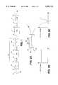
- FIG. 1is a block diagram of an embodiment of the invention
- FIG. 2Ais a schematic diagram of a filter formed of an optical fiber coupler
- FIG. 2Bis a diagram of an example spectrum of input light to the filter of FIG. 2A
- FIG. 2Cis a diagram of an example spectrum of output light from the filter of FIG. 2A.
- FIG. 3Ais a diagram of a natural amplified spontaneous emission spectrum
- FIG. 3Bis a diagram of the seed signal spectrum after filtering
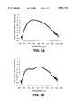
- FIG. 4Ais the final output spectrum of the signal generator of the present invention plotted on a linear scale
- FIG. 4Bis the final output spectrum of the signal generator of the present invention plotted on a logarithmic scale
- FIG. 5is a block diagram of another embodiment of the invention.
- FIGS. 6 and 7respectively illustrate imaging and sensor systems which utilize the novel broadband source described herein.
- a semiconductor optical amplifier 1is an example of an amplification medium used in this embodiment.
- the amplifierhas two output ports, one being an output port 2 and another being a backward propagating port 6.
- the output port 2is fusion spliced to the input 3 of a single or double stage polarization independent optical isolator 4.
- the output 5 of the isolatoris the output of the entire device.
- the purpose of the isolator 4is to avoid perturbation of the back reflection after output, and therefore this element can be deleted if other means are taken to avoid this perturbation.
- the backward propagating port 6is fusion spliced to the input 7 of a control loop 7A.
- a single arm control loopis shown, although a multi-arm control loop can be used, as will be described later.
- the loop 7Ais comprised of a reflector 8A formed of a gold-covered tip of an optical fiber carrying the optical signal.
- the fiber pigtail 8which ends in the reflector 8A is fusion spliced to the input 9 of an optional Faraday polarization rotator 10.
- the rotator output 11is fusion spliced to the input 12 of an optional attenuator 13.
- the attenuator output arm 14is fusion spliced to a reshaping filter 16 via input 15.
- the filter output 7is also the control loop 7A output, which is fusion spliced to the amplifier 1 backward light propagating port.
- the Faraday polarazation rotator 10 and attenuator 13are optional devices, and are used depending on whether fed back light power exceeds the optical amplifier lasing threhold.
- the polarization rotator, attenuator and reshaping filterare all bidirectional devices, i.e. their inputs can also be their outputs. If used, the order of these devices can be changed, and by adjusting the attenuation, the desired result can be achieved.
- the optical amplification medium 1forms a fluorescent light emitting material.
- the optical amplification mediumcan for example be a doped fiber amplifier (DFA), or a semiconductor based optical amplifier (SOA).
- DFAdoped fiber amplifier
- SOAsemiconductor based optical amplifier
- Amplified spontaneous emission (ASE)is generated via an energy transfer either optically or electronically.
- ASEwhich is generated propagates in two directions: one forward propagating (i.e. in the same direction as the signal when it is used as an amplifier), and the other is backward propagating (i.e. propagating in the reverse direction as compared to the usual propagation direction).
- the forward propagating lightis emitted at port 2 and the backward propagating light is emitted at port 6.
- the DFA or SOAis used both as a seed light generator and as a light emitter.
- the backward propagating ASEis used to generate seed light in a passive fiber optic control loop 7A.
- the control loopreshapes the spectrum and sends the light back to the amplification medium 1 via the backward light propagating port 6.
- the control loop 7Aspectrum shapes and rebalances the light fed back to the amplification medium, with a notch, or reduced amplitude within a band, which can be centered to the amplifier 1 gain peak or ASE peak, although the reduced amplitude band can be located over any useful region.
- the output of the amplifieris spectrum reshaped. Due to the strong seed signal, the amplifier functions in saturation and outputs a strong and broad spectrum with a desired shape.
- the gain peakwas at approximately 1320 nm, and the filter was centered as 1290 nm.
- an active light emitting devicesuch as a super luminescent diode
- a wavelength dependent filter and/or attenuatorit is preferred to use the above-described structure rather than an active light emitting device such as a super luminescent diode together with a wavelength dependent filter and/or attenuator, because the latter structure involves high cost and system complexity.
- the present inventionas described above provides a completely passive, easy to configure and low cost control loop 7A.
- an active emittersuch as a superluminescent diode (SLD) can replace the passive reflector and the rotator and attenuator, as long as the bandwidth of the SLD broad enough to provide sufficient seed signal (spectral width and intensity).
- SLDsuperluminescent diode
- the reshaping element 11is preferably a wavelength dependent attenuator (filter).
- the filtercan be formed of a thin film based device, or a fiber grating device.
- thin film based devicesare very costly and are difficult to manufacture.
- Fiber grating devices(such as Bragg grating and long period grating) are prone to instabilities with temperature change and introduce spectral ripples, and at this time are difficult to design to provide the desired bandwidth and filter shape.
- the coupleris formed of an optical fiber 20 which has its cladding fused at a narrowed coupling region 22 to the cladding of another optical fiber 23.
- Fiber 20carries the optical signal between ports 7 and 15.
- Fiber 23has short stubs on either side of the coupling region 22. Fiber 23 absorbs some of the light content with a wavelength dependence such that the remaining light transmitted by fiber 20 has a notch or a decrease in amplitude in its spectrum, which is centered with the amplification gain curve of the optical amplifier. This can be seen in FIG. 2B which illustrates the amplitude of a representative input signal with respect to wavelength to the coupler via optical fiber 20, and in FIG. 2C which illustrates the amplitude of a representative output signal with respect to wavelength from the coupler via optical fiber 20.
- optical amplifiersare only one step from forming a laser.
- An optical amplifier placed in a cavity consisting of reflective mirrorswill emit coherent laser light.
- the coherence length of the lightis required to be minimized.
- the backward propagating ASE fed back to the amplifieris in phase with the forward propagating ASE. If the feedback exceeds the lasing threshold, laser effects occur and the source coherence length is increased. Therefore, the amount of light that can be fed back is limited to being below the lasing threshold.
- a polarization scrambler or rotator 10can be used.
- This elementcan be for example a Lyot depolarizer, or a Faraday rotator. Either, or other devices which achieve polarization scrambling or rotation can be used to increase the lasing threshold sufficiently to avoid lasing effects.
- the reflector 8A at the end of the fiber 8can be a well known gold reflective coating on a smoothed tip of the fiber.
- a bi-directional fused coupler with a defined coupling ratiocan be used in its place, its two output arms fusion spliced together, as described in U.S. patent application Ser. No. 08/914,163 and is incorporated herein by reference.
- a SLD as described above, or any device which returns light applied to itshould be construed as being a reflector can be used.
- FIG. 3Aillustrates an example of an ASE spectrum generated by the optical amplifier, backward ASE being used to generate the filtered seed light.
- FIG. 3Billustrates an example of the seed light spectrum after filtering.
- the filter width, depth and center wavelengthcan be adjusted.
- the 5 dB down points of the ASE signalare at about 1270 and 1350 nm, while those of the signal spectrum after filtering are at about 1260 and 1372 nm.
- FIG. 4Ais the final output spectrum of the signal generator of an embodiment of the present invention plotted on a linear scale
- FIG. 4Bis the final output spectrum of the signal generator of that embodiment of the present invention plotted on a logarithmic scale. Smoothness, relative constancy over the high amplitude portion of the spectrum as well as the increased bandwidth over the original naturally generated light is evident.
- FIG. 5illustrates a multiple arm (in this case a double arm) structure.
- Each of the armsis comprised of a filter 16A, 16B, which are spliced to a 50/50 (or other ratio) coupler 30.
- the coupleris also spliced to the backward light propagating port of the amplifier 1 (not shown in FIG. 5.
- filters 16A and 16Bare coupled to reflectors 8B and 8C, which as described earlier can be mirrors formed by the gold coatings at the tips of the fibers which carry the optical signals, or which can be formed by the couplers or other devices described above and in the aforenoted U.S. patent application.
- one or more of an attenuator and polarization rotatoris coupled in series with the filter and mirror in each arm, as described above with respect to the single arm structure, and which operates in a similar manner and for the same reason, i.e. to raise the lasing threshold of the amplifier.
- Each of the filterscan have its own frequency response, to reduce the amplitude of a portion of the light to be fed back to the amplifier, in order to flatten the overall output signal from the optical signal generator. Indeed, the decreased amplitude bands can overlap, and one band can completely envelop the other.
- the low coherence sourcecan be used for high speed imaging in a system as shown in FIG. 6.
- a low coherence source 40such as that described herein provides optical light to a 50/50 coupler 41.
- One of the ports of the coupleris fed via optics 42 to a reference mirror 44.
- Another of the portsis coupled via scanning optics 46 to a sample 48.
- the remaining portif the coupler is coupled to a detector 50, the output signal of which is demodulated in demodulator 52.
- the demodulated signalis converted to digital in analog to digital converter 54, from which it is fed to the input of a computer 56 for analysis.
- the structureprovides low coherence interferometry in the coupler 41 between the scanned sample signal and the signal reflected in the reference mirror, which is analyzed in computer 56.
- the present inventionin such an imaging system, that system can be used for the first time in real diagnostics on live people, because the present invention allows imaging at a speed of a few tens of images per second (e.g. 32 images per second).
- a few tens of images per seconde.g. 32 images per second.
- prior art light sourcessuch as LEDs or SLDs, one image required several seconds. Since live human tissue or cells is constantly in motion, the prior art light sources would allow imaging only of dead (still) bodies.
- FIG. 7illustrates a block diagram for using the broadband source described above in a fiber temperature or strain sensor system.
- the source 46is coupled to an optical coupler 60.
- the fiber carrying the input lightis coupled to a fiber Bragg grating or network 62.
- the other (coupled) fiberhas one end 64 terminated, or is used for a reference, and its other end coupled to a light detection and processing system 66.
- the light generated by source 46 and reflected by the gratings 62is coupled to the other fiber by coupler 60, and is processed by the signal detection and processing system 66.
- the present inventionallows e.g. 16-32 sensors to share a single source, while prior art LED or SLD light sources each could drive a single sensor, with one elctronic driver for each diode.
- the present inventionthus reduces the cost of sensor applications substantially.
Landscapes
- Physics & Mathematics (AREA)
- Condensed Matter Physics & Semiconductors (AREA)
- General Physics & Mathematics (AREA)
- Electromagnetism (AREA)
- Optics & Photonics (AREA)
- Lasers (AREA)
Abstract
Description
This invention relates to the field of optical light sources, and in particular to an optical low coherence light source having broad spectrum width and emitting single transverse mode light of which the intensity is typically a few thousand time stronger than regular light emitting diodes (LEDs).
Low coherence broadband optical sources are required for optical imaging and optical sensors. Such sources are used for example in coherence domain optical tomography, some medical diagnostic technology such as Doppler velocimeters, remote sensors for detecting temperature, pressure, strain, etc., low coherence light source based fiber optic gyroscopes, fiber optic instrumentation, etc.
Such applications have very high optical light source spectrum width and shape requirements as well as power density of the main optical emitter or lighting device. For example, in optical imaging, the imaging resolution, defined by RES=f(λ)*1/Δλ, Δλ being the spectral width and f(λ) a function depending on source wavelength, changes with the optical source bandwidth. Thus when the source spectrum is broader, the resolution is greater and more detail can be seen by the imaging system. In an optical sensor application, a greater optical emitter bandwidth means more sensors can be included in a single sensing system sharing the same optical source, and the whole sensor system cost can be lower since fewer optical emitters can be used.
The power level of the source is also of concern, since the sensor system loss budget can be greater with a higher power optical source. Total power of the source determines the imaging or sensor system loss that can be tolerated. Loss is caused by the high light scattering nature of the human tissue into which the light caused to penetrate. Higher power represents deeper penetration of the light into the tissue under diagnosis.
More importantly, the power of the source determines the imaging speed, which determines whether the source can be used to do in-vivo disease detection in hospitals and clinics.
In the case of fiber optic temperature or strain sensing, hard to reach regions where sensors (such as fiber Bragg grating based sensors) are introduced can introduce large losses, either due to long light transmission distances or due to fiber bending. Higher emitter power can increase the sensitivity of the sensor.
The spectrum shape of the light source is also important, particularly for optical imaging systems in which a quasi-Gaussian spectrum shape is required for clean and sharp image quality.
The present invention provides a low cost power and bandwidth enhanced low-coherence optical light source which is suitable for the above applications.
A spectrum broadened and power enhanced fiber optic light source can be fabricated from an active optical amplification medium such as rare earth doped fiber or a semiconductor optical amplifier. The output power is greatly enhanced and the spectrum widely broadened after feeding back a reshaped and optionally polarization scrambled backward propagating amplified spontaneous emission originating from the amplification medium itself.
In accordance with an embodiment of the invention, an optical light source signal generator comprises (a) an optical amplification medium for generating amplified spontaneous emission (ASE), having forward and backward light propagating ports for outputting output and backward optical light respectively, (b) a reflector for reflecting the backward propagating optical light back toward the backward light propagating port, and (c) an optical light spectrum reshaper interposed between the reflector and the backward light propagating port for transmitting the reflected light to the backward light propagating port with a wavelength dependence having a reduced amplitude in a band coinciding with an undesired high gain band of the optical amplification medium.
In accordance with another embodiment, a method of generating a low-coherence optical light, comprises generating, in an ASE light generator, output and backward emitted optical amplified spontaneous emission (ASE) light, passing the backward emitted optical light through an optical light spectrum reshaper and feeding back spectrum reshaped light to the light generator for modifying the low coherence optical light source in accordance with the spectrum reshaped light, so as to obtain modified spectrum output light.
Preferably the spectrum reshaper decreases the amplitude of the light to be fed back in a band in which the light generator has undesirably high gain.
In accordance with another embodiment, the light which is fed back is polarization scrambled, which when fed back does not cause lasing of the ASE light generator.
A better understanding of the invention will be obtained by a consideration of the detailed description below, in conjunction with the following drawings, in which:
FIG. 1 is a block diagram of an embodiment of the invention,
FIG. 2A is a schematic diagram of a filter formed of an optical fiber coupler,
FIG. 2B is a diagram of an example spectrum of input light to the filter of FIG. 2A,
FIG. 2C is a diagram of an example spectrum of output light from the filter of FIG. 2A,
FIG. 3A is a diagram of a natural amplified spontaneous emission spectrum,
FIG. 3B is a diagram of the seed signal spectrum after filtering,
FIG. 4A is the final output spectrum of the signal generator of the present invention plotted on a linear scale,
FIG. 4B is the final output spectrum of the signal generator of the present invention plotted on a logarithmic scale,
FIG. 5 is a block diagram of another embodiment of the invention, and
FIGS. 6 and 7 respectively illustrate imaging and sensor systems which utilize the novel broadband source described herein.
As shown in FIG. 1, a semiconductoroptical amplifier 1 is an example of an amplification medium used in this embodiment. The amplifier has two output ports, one being anoutput port 2 and another being a backward propagating port 6. Theoutput port 2 is fusion spliced to the input 3 of a single or double stage polarization independent optical isolator 4. Theoutput 5 of the isolator is the output of the entire device. The purpose of the isolator 4 is to avoid perturbation of the back reflection after output, and therefore this element can be deleted if other means are taken to avoid this perturbation.
The backward propagating port 6 is fusion spliced to the input 7 of acontrol loop 7A. In this embodiment, a single arm control loop is shown, although a multi-arm control loop can be used, as will be described later.
Theloop 7A is comprised of areflector 8A formed of a gold-covered tip of an optical fiber carrying the optical signal. Thefiber pigtail 8 which ends in thereflector 8A is fusion spliced to theinput 9 of an optionalFaraday polarization rotator 10. Therotator output 11 is fusion spliced to theinput 12 of anoptional attenuator 13. The attenuator output arm 14 is fusion spliced to a reshapingfilter 16 viainput 15. The filter output 7 is also thecontrol loop 7A output, which is fusion spliced to theamplifier 1 backward light propagating port.
As will be noted later, the Faradaypolarazation rotator 10 andattenuator 13 are optional devices, and are used depending on whether fed back light power exceeds the optical amplifier lasing threhold. The polarization rotator, attenuator and reshaping filter are all bidirectional devices, i.e. their inputs can also be their outputs. If used, the order of these devices can be changed, and by adjusting the attenuation, the desired result can be achieved.
In operation, theoptical amplification medium 1 forms a fluorescent light emitting material. The optical amplification medium can for example be a doped fiber amplifier (DFA), or a semiconductor based optical amplifier (SOA). Amplified spontaneous emission (ASE) is generated via an energy transfer either optically or electronically. ASE which is generated propagates in two directions: one forward propagating (i.e. in the same direction as the signal when it is used as an amplifier), and the other is backward propagating (i.e. propagating in the reverse direction as compared to the usual propagation direction). The forward propagating light is emitted atport 2 and the backward propagating light is emitted at port 6.
In this invention, the DFA or SOA is used both as a seed light generator and as a light emitter. The backward propagating ASE is used to generate seed light in a passive fiberoptic control loop 7A. The control loop reshapes the spectrum and sends the light back to theamplification medium 1 via the backward light propagating port 6.
Thecontrol loop 7A spectrum shapes and rebalances the light fed back to the amplification medium, with a notch, or reduced amplitude within a band, which can be centered to theamplifier 1 gain peak or ASE peak, although the reduced amplitude band can be located over any useful region. With this modified light amplified, the output of the amplifier is spectrum reshaped. Due to the strong seed signal, the amplifier functions in saturation and outputs a strong and broad spectrum with a desired shape.
In one successful embodiment, the gain peak was at approximately 1320 nm, and the filter was centered as 1290 nm.
It is preferred to use the above-described structure rather than an active light emitting device such as a super luminescent diode together with a wavelength dependent filter and/or attenuator, because the latter structure involves high cost and system complexity. The present invention as described above provides a completely passive, easy to configure and lowcost control loop 7A. However, an active emitter such as a superluminescent diode (SLD) can replace the passive reflector and the rotator and attenuator, as long as the bandwidth of the SLD broad enough to provide sufficient seed signal (spectral width and intensity).
The reshapingelement 11 is preferably a wavelength dependent attenuator (filter). The filter can be formed of a thin film based device, or a fiber grating device. However, thin film based devices are very costly and are difficult to manufacture. Fiber grating devices (such as Bragg grating and long period grating) are prone to instabilities with temperature change and introduce spectral ripples, and at this time are difficult to design to provide the desired bandwidth and filter shape.
It is preferred that a fused optical coupler should be used, such as is shown in FIG. 2A. The coupler is formed of anoptical fiber 20 which has its cladding fused at a narrowedcoupling region 22 to the cladding of anotheroptical fiber 23.
It is well known that optical amplifiers are only one step from forming a laser. An optical amplifier placed in a cavity consisting of reflective mirrors will emit coherent laser light. However, for low-coherence source applications, as in the present invention, the coherence length of the light is required to be minimized.
In the light generator configuration as described herein, the backward propagating ASE fed back to the amplifier is in phase with the forward propagating ASE. If the feedback exceeds the lasing threshold, laser effects occur and the source coherence length is increased. Therefore, the amount of light that can be fed back is limited to being below the lasing threshold.
Because the optical amplifier output power depends strongly on the amount of the input seed light up to deep saturation, in order to be able to send as strong as possible light back to the amplifier without lasing, a polarization scrambler orrotator 10 can be used. This element can be for example a Lyot depolarizer, or a Faraday rotator. Either, or other devices which achieve polarization scrambling or rotation can be used to increase the lasing threshold sufficiently to avoid lasing effects.
Thereflector 8A at the end of thefiber 8 can be a well known gold reflective coating on a smoothed tip of the fiber. Alternatively, a bi-directional fused coupler with a defined coupling ratio can be used in its place, its two output arms fusion spliced together, as described in U.S. patent application Ser. No. 08/914,163 and is incorporated herein by reference. For the purposes of this specification, both of the above, a SLD as described above, or any device which returns light applied to it should be construed as being a reflector can be used.
FIG. 3A illustrates an example of an ASE spectrum generated by the optical amplifier, backward ASE being used to generate the filtered seed light. FIG. 3B illustrates an example of the seed light spectrum after filtering. Depending on the desired spectrum shape and final output level, as well as optical amplifier characteristics, the filter width, depth and center wavelength can be adjusted. As may be seen in FIG. 3A, the 5 dB down points of the ASE signal are at about 1270 and 1350 nm, while those of the signal spectrum after filtering are at about 1260 and 1372 nm.
FIG. 4A is the final output spectrum of the signal generator of an embodiment of the present invention plotted on a linear scale, and FIG. 4B is the final output spectrum of the signal generator of that embodiment of the present invention plotted on a logarithmic scale. Smoothness, relative constancy over the high amplitude portion of the spectrum as well as the increased bandwidth over the original naturally generated light is evident.
While the description above relates to a single arm seed light generator, FIG. 5 illustrates a multiple arm (in this case a double arm) structure. Each of the arms is comprised of afilter coupler 30. The coupler is also spliced to the backward light propagating port of the amplifier 1 (not shown in FIG. 5.
The other ports offilters reflectors
Optionally, one or more of an attenuator and polarization rotator is coupled in series with the filter and mirror in each arm, as described above with respect to the single arm structure, and which operates in a similar manner and for the same reason, i.e. to raise the lasing threshold of the amplifier.
Each of the filters can have its own frequency response, to reduce the amplitude of a portion of the light to be fed back to the amplifier, in order to flatten the overall output signal from the optical signal generator. Indeed, the decreased amplitude bands can overlap, and one band can completely envelop the other.
The low coherence source can be used for high speed imaging in a system as shown in FIG. 6. Alow coherence source 40 such as that described herein provides optical light to a 50/50coupler 41. One of the ports of the coupler is fed viaoptics 42 to areference mirror 44. Another of the ports is coupled via scanningoptics 46 to asample 48. The remaining port if the coupler is coupled to adetector 50, the output signal of which is demodulated indemodulator 52. The demodulated signal is converted to digital in analog todigital converter 54, from which it is fed to the input of acomputer 56 for analysis.
The structure provides low coherence interferometry in thecoupler 41 between the scanned sample signal and the signal reflected in the reference mirror, which is analyzed incomputer 56.
By the use of the present invention in such an imaging system, that system can be used for the first time in real diagnostics on live people, because the present invention allows imaging at a speed of a few tens of images per second (e.g. 32 images per second). Using prior art light sources such as LEDs or SLDs, one image required several seconds. Since live human tissue or cells is constantly in motion, the prior art light sources would allow imaging only of dead (still) bodies.
FIG. 7 illustrates a block diagram for using the broadband source described above in a fiber temperature or strain sensor system. Thesource 46 is coupled to anoptical coupler 60. The fiber carrying the input light is coupled to a fiber Bragg grating ornetwork 62. The other (coupled) fiber has oneend 64 terminated, or is used for a reference, and its other end coupled to a light detection andprocessing system 66.
The light generated bysource 46 and reflected by thegratings 62 is coupled to the other fiber bycoupler 60, and is processed by the signal detection andprocessing system 66.
The present invention allows e.g. 16-32 sensors to share a single source, while prior art LED or SLD light sources each could drive a single sensor, with one elctronic driver for each diode. The present invention thus reduces the cost of sensor applications substantially.
A person understanding this invention may now conceive of alternate embodiments and enhancements using the principles described herein. All such embodiments and enhancements are considered to be within the spirit and scope of this invention as defined in the claims appended hereto.
Claims (13)
1. An optical light source signal generator comprising:
(a) an optical amplification medium for generating amplified spontaneous emission (ASE), having forward and backward light propagating ports for outputting output and backward optical light respectively,
(b) a reflector for reflecting the backward propagating optical light back toward the backward light propagating port, and
(c) an optical light spectrum reshaper interposed between the reflector and the backward light propagating port for transmitting the reflected light to the backward light propagating port with a wavelength dependence having a reduced amplitude in a band coinciding with an undesired high gain band of the optical amplification medium.
2. A generator as defined in claim 1 in which the optical light spectrum reshaper is comprised of a filter formed of one of a thin film deposit device, a filter grating device, and a fused optical coupler.
3. A generator as defined in claim 2 further including at least one of a light polarization scrambling or rotating element and an optical attenuator coupled in series with the reshaper.
4. A generator as defined in claim 1 in which the optical light spectrum reshaper is comprised of a filter formed of a fused optical coupler comprised of a pair of optical fibers having fused claddings in a coupling region, one of the optical fibers having an end coupled to the backward light propagating port and another end coupled to the reflector, the other of the optical fibers being formed as short stubs on opposite sides of the coupler, and absorbing light in said band from said one of the optical fibers.
5. A generator as defined in claim 4 further including at least one of a light polarization scrambling or rotating element and an optical attenuator coupled in series with the reshaper.
6. A generator as defined in claim 5, in which the reflector is a gold coated planar end to said one of the optical fibers, forming a mirror.
7. A generator as defined in claim 4, in which the reflector is a gold coated planar end to said one of the optical fibers, forming a mirror.
8. A generator as defined in claim 1, further including a first coupler having one bidirectional output port coupled to the reshaper and having a bidirectional input port coupled to the backward light propagating port, and a second light spectrum reshaper coupled between another bidirectional output port of the first coupler and a second reflector for transmitting a second reflected signal to the backward light propagating port via the first coupler with a wavelength dependence having a reduced amplitude in a second band coinciding with a second high gain band of the optical amplification medium.
9. A generator as defined in claim 8 in which each of the optical signal spectrum reshapers is comprised of a filter formed of a fused optical coupler comprised of a pair of optical fibers having fused claddings, one of the optical fibers of each fused optical coupler having an end coupled via the first coupler to the backward light propagating port and another end coupled to a corresponding reflector, the other of the optical fibers of the respective fused optical couplers being formed as short stubs on opposite sides thereof and absorbing light in a respective band from a corresponding one of said one of the optical fibers.
10. A generator as defined in claim 9 further including at least one of a polarizing scrambling or rotating element and an optical attenuator connected in series with a corresponding optical signal reshaper.
11. A method of generating a low-coherence optical light, comprising generating, in an ASE light generator, output and backward emitted optical amplified spontaneous emission (ASE) light, passing the backward emitted optical light through an optical light spectrum reshaper and feeding back spectrum reshaped light to the light generator for modifying the low coherence optical light source in accordance with the spectrum reshaped light, so as to obtain modified spectrum output light.
12. A method as defined in claim 11 including decreasing the amplitude of the light to be fed back in a band in which the signal generator has undesirably high gain.
13. A method as defined in claim 12, including polarization scrambling or rotating the light to be fed back.
Priority Applications (1)
| Application Number | Priority Date | Filing Date | Title |
|---|---|---|---|
| US09/026,654US6091743A (en) | 1998-02-20 | 1998-02-20 | Bandwidth broadened and power enhanced low coherence fiberoptic light source |
Applications Claiming Priority (1)
| Application Number | Priority Date | Filing Date | Title |
|---|---|---|---|
| US09/026,654US6091743A (en) | 1998-02-20 | 1998-02-20 | Bandwidth broadened and power enhanced low coherence fiberoptic light source |
Publications (1)
| Publication Number | Publication Date |
|---|---|
| US6091743Atrue US6091743A (en) | 2000-07-18 |
Family
ID=21833078
Family Applications (1)
| Application Number | Title | Priority Date | Filing Date |
|---|---|---|---|
| US09/026,654Expired - Fee RelatedUS6091743A (en) | 1998-02-20 | 1998-02-20 | Bandwidth broadened and power enhanced low coherence fiberoptic light source |
Country Status (1)
| Country | Link |
|---|---|
| US (1) | US6091743A (en) |
Cited By (24)
| Publication number | Priority date | Publication date | Assignee | Title |
|---|---|---|---|---|
| US6317254B1 (en)* | 1998-11-24 | 2001-11-13 | Samsung Electronics Co., Ltd. | Parallel optical fiber amplifier with high power conversion |
| FR2815410A1 (en)* | 2000-10-18 | 2002-04-19 | Ando Electric | Low coherence reflectometer, which is used for measurement of reflective dispersion in optical circuits, suppresses chromatic dispersion effects and thus improves the spatial resolution of measurements |
| US6424762B1 (en)* | 2000-03-07 | 2002-07-23 | Institut National D'optique | Superfluorescent fiber source |
| US6483628B1 (en)* | 1999-09-20 | 2002-11-19 | The Board Of Trustees Of The Leland Stanford Junior University | Polarization and wavelength stable superfluorescent sources using Faraday rotator mirrors |
| US20040246567A1 (en)* | 2003-06-09 | 2004-12-09 | Joon Tae Ahn | Gain-clamped optical amplifier |
| US20050052739A1 (en)* | 2003-05-23 | 2005-03-10 | Yu Anthony W. | Methods and devices for high power, depolarized superluminescent diodes |
| US20050185262A1 (en)* | 2003-12-18 | 2005-08-25 | In-Kuk Yun | Broadband light source |
| US20050191061A1 (en)* | 2004-02-27 | 2005-09-01 | Xiang Liu | Optical commnication method and apparatus |
| US20080193144A1 (en)* | 2007-02-08 | 2008-08-14 | Finisar Corporation | Slow chirp compensation for enhanced signal bandwidth and transmission performances in directly modulated lasers |
| US20080240180A1 (en)* | 2002-12-03 | 2008-10-02 | Finisar Corporation | Optical fm source based on intra-cavity phase and amplitude modulation in lasers |
| US20080247763A1 (en)* | 2007-04-06 | 2008-10-09 | Finisar Corporation | Chirped laser with passive filter element for differential phase shift keying generation |
| US7962044B2 (en) | 2007-02-02 | 2011-06-14 | Finisar Corporation | Temperature stabilizing packaging for optoelectronic components in a transmitter module |
| US7962045B2 (en) | 2006-12-22 | 2011-06-14 | Finisar Corporation | Optical transmitter having a widely tunable directly modulated laser and periodic optical spectrum reshaping element |
| US7991291B2 (en) | 2007-02-08 | 2011-08-02 | Finisar Corporation | WDM PON based on DML |
| US8131157B2 (en) | 2007-01-22 | 2012-03-06 | Finisar Corporation | Method and apparatus for generating signals with increased dispersion tolerance using a directly modulated laser transmitter |
| US8160455B2 (en) | 2008-01-22 | 2012-04-17 | Finisar Corporation | Method and apparatus for generating signals with increased dispersion tolerance using a directly modulated laser transmitter |
| US8199785B2 (en) | 2009-06-30 | 2012-06-12 | Finisar Corporation | Thermal chirp compensation in a chirp managed laser |
| US8204386B2 (en) | 2007-04-06 | 2012-06-19 | Finisar Corporation | Chirped laser with passive filter element for differential phase shift keying generation |
| US20120155876A1 (en)* | 2010-12-21 | 2012-06-21 | Electronics And Telecommunications Research Institute | Seed light module for wavelength division multiplexing-passive optical network and method for driving the same |
| US8260150B2 (en) | 2008-04-25 | 2012-09-04 | Finisar Corporation | Passive wave division multiplexed transmitter having a directly modulated laser array |
| US8792531B2 (en) | 2003-02-25 | 2014-07-29 | Finisar Corporation | Optical beam steering for tunable laser applications |
| US9002214B2 (en) | 2011-07-14 | 2015-04-07 | Applied Optoelectronics, Inc. | Wavelength-selectable laser device and apparatus and system including same |
| US9214790B2 (en)* | 2012-10-03 | 2015-12-15 | Applied Optoelectronics, Inc. | Filtered laser array assembly with external optical modulation and WDM optical system including same |
| US9502858B2 (en) | 2011-07-14 | 2016-11-22 | Applied Optoelectronics, Inc. | Laser array mux assembly with external reflector for providing a selected wavelength or multiplexed wavelengths |
Citations (3)
| Publication number | Priority date | Publication date | Assignee | Title |
|---|---|---|---|---|
| US5177634A (en)* | 1991-10-25 | 1993-01-05 | Bell Communications Research, Inc. | High gain limiting erbium-doped fiber amplifier with wide dynamic range |
| US5808788A (en)* | 1996-01-29 | 1998-09-15 | Samsung Electronics Co., Ltd. | Optical fiber amplifier |
| US5818630A (en)* | 1997-06-25 | 1998-10-06 | Imra America, Inc. | Single-mode amplifiers and compressors based on multi-mode fibers |
- 1998
- 1998-02-20USUS09/026,654patent/US6091743A/ennot_activeExpired - Fee Related
Patent Citations (3)
| Publication number | Priority date | Publication date | Assignee | Title |
|---|---|---|---|---|
| US5177634A (en)* | 1991-10-25 | 1993-01-05 | Bell Communications Research, Inc. | High gain limiting erbium-doped fiber amplifier with wide dynamic range |
| US5808788A (en)* | 1996-01-29 | 1998-09-15 | Samsung Electronics Co., Ltd. | Optical fiber amplifier |
| US5818630A (en)* | 1997-06-25 | 1998-10-06 | Imra America, Inc. | Single-mode amplifiers and compressors based on multi-mode fibers |
Cited By (31)
| Publication number | Priority date | Publication date | Assignee | Title |
|---|---|---|---|---|
| US6317254B1 (en)* | 1998-11-24 | 2001-11-13 | Samsung Electronics Co., Ltd. | Parallel optical fiber amplifier with high power conversion |
| US6483628B1 (en)* | 1999-09-20 | 2002-11-19 | The Board Of Trustees Of The Leland Stanford Junior University | Polarization and wavelength stable superfluorescent sources using Faraday rotator mirrors |
| US6424762B1 (en)* | 2000-03-07 | 2002-07-23 | Institut National D'optique | Superfluorescent fiber source |
| FR2815410A1 (en)* | 2000-10-18 | 2002-04-19 | Ando Electric | Low coherence reflectometer, which is used for measurement of reflective dispersion in optical circuits, suppresses chromatic dispersion effects and thus improves the spatial resolution of measurements |
| US20020060794A1 (en)* | 2000-10-18 | 2002-05-23 | Ando Electric Co., Ltd. | Low coherent reflectometer |
| US20080240180A1 (en)* | 2002-12-03 | 2008-10-02 | Finisar Corporation | Optical fm source based on intra-cavity phase and amplitude modulation in lasers |
| US7907648B2 (en)* | 2002-12-03 | 2011-03-15 | Finisar Corporation | Optical FM source based on intra-cavity phase and amplitude modulation in lasers |
| US8792531B2 (en) | 2003-02-25 | 2014-07-29 | Finisar Corporation | Optical beam steering for tunable laser applications |
| US20050052739A1 (en)* | 2003-05-23 | 2005-03-10 | Yu Anthony W. | Methods and devices for high power, depolarized superluminescent diodes |
| US7050222B2 (en)* | 2003-05-23 | 2006-05-23 | Covega, Inc. | Methods and devices for high power, depolarized superluminescent diodes |
| US20040246567A1 (en)* | 2003-06-09 | 2004-12-09 | Joon Tae Ahn | Gain-clamped optical amplifier |
| US20050185262A1 (en)* | 2003-12-18 | 2005-08-25 | In-Kuk Yun | Broadband light source |
| US7236295B2 (en)* | 2003-12-18 | 2007-06-26 | Samsung Electronics Co., Ltd. | Broadband light source |
| US8045862B2 (en)* | 2004-02-27 | 2011-10-25 | Alcatel Lucent | Optical communication method and apparatus |
| US20050191061A1 (en)* | 2004-02-27 | 2005-09-01 | Xiang Liu | Optical commnication method and apparatus |
| US7962045B2 (en) | 2006-12-22 | 2011-06-14 | Finisar Corporation | Optical transmitter having a widely tunable directly modulated laser and periodic optical spectrum reshaping element |
| US8131157B2 (en) | 2007-01-22 | 2012-03-06 | Finisar Corporation | Method and apparatus for generating signals with increased dispersion tolerance using a directly modulated laser transmitter |
| US7962044B2 (en) | 2007-02-02 | 2011-06-14 | Finisar Corporation | Temperature stabilizing packaging for optoelectronic components in a transmitter module |
| US7991291B2 (en) | 2007-02-08 | 2011-08-02 | Finisar Corporation | WDM PON based on DML |
| US8027593B2 (en) | 2007-02-08 | 2011-09-27 | Finisar Corporation | Slow chirp compensation for enhanced signal bandwidth and transmission performances in directly modulated lasers |
| US20080193144A1 (en)* | 2007-02-08 | 2008-08-14 | Finisar Corporation | Slow chirp compensation for enhanced signal bandwidth and transmission performances in directly modulated lasers |
| US8204386B2 (en) | 2007-04-06 | 2012-06-19 | Finisar Corporation | Chirped laser with passive filter element for differential phase shift keying generation |
| US7991297B2 (en) | 2007-04-06 | 2011-08-02 | Finisar Corporation | Chirped laser with passive filter element for differential phase shift keying generation |
| US20080247763A1 (en)* | 2007-04-06 | 2008-10-09 | Finisar Corporation | Chirped laser with passive filter element for differential phase shift keying generation |
| US8160455B2 (en) | 2008-01-22 | 2012-04-17 | Finisar Corporation | Method and apparatus for generating signals with increased dispersion tolerance using a directly modulated laser transmitter |
| US8260150B2 (en) | 2008-04-25 | 2012-09-04 | Finisar Corporation | Passive wave division multiplexed transmitter having a directly modulated laser array |
| US8199785B2 (en) | 2009-06-30 | 2012-06-12 | Finisar Corporation | Thermal chirp compensation in a chirp managed laser |
| US20120155876A1 (en)* | 2010-12-21 | 2012-06-21 | Electronics And Telecommunications Research Institute | Seed light module for wavelength division multiplexing-passive optical network and method for driving the same |
| US9002214B2 (en) | 2011-07-14 | 2015-04-07 | Applied Optoelectronics, Inc. | Wavelength-selectable laser device and apparatus and system including same |
| US9502858B2 (en) | 2011-07-14 | 2016-11-22 | Applied Optoelectronics, Inc. | Laser array mux assembly with external reflector for providing a selected wavelength or multiplexed wavelengths |
| US9214790B2 (en)* | 2012-10-03 | 2015-12-15 | Applied Optoelectronics, Inc. | Filtered laser array assembly with external optical modulation and WDM optical system including same |
Similar Documents
| Publication | Publication Date | Title |
|---|---|---|
| US6091743A (en) | Bandwidth broadened and power enhanced low coherence fiberoptic light source | |
| CA2421113C (en) | Optical amplification in coherence reflectometry | |
| US8269977B2 (en) | Discrete spectrum broadband optical source | |
| US6900943B2 (en) | Optical amplification in coherent optical frequency modulated continuous wave reflectometry | |
| CA3023766C (en) | A fiber optic interrogation system for multiple distributed sensing systems | |
| US20140177660A1 (en) | Wavelength stabilization | |
| CA2064719C (en) | Interferometer utilizing superfluorescent optical source | |
| US5732046A (en) | Active fiber-optic opto-acoustic detector | |
| JP3999437B2 (en) | Optical tomographic imaging system | |
| KR20010100925A (en) | Ultrasonic probe, ultrasonic receiver and ultrasonic diagnostic apparatus | |
| WO2006091274A1 (en) | Reducing spectral noise in semiconductor spectroscopy system | |
| JP3668108B2 (en) | Article having optical fiber light source | |
| US20040239942A1 (en) | Optical coherence tomography device | |
| JP2014063042A (en) | Supercontinuum light source and optical tomography measurement device | |
| US9383263B2 (en) | Systems and methods for narrowing a wavelength emission of light | |
| JP2003515151A (en) | Optical fiber interferometer | |
| CN107271027B (en) | Optical fiber sound wave sensing system based on broadband weak reflecting mirror and random laser | |
| CN208045930U (en) | A kind of optical fiber laser of length scanning | |
| JP2009060022A (en) | Wavelength-scanning light source | |
| CN208707066U (en) | A kind of optical fiber laser of the length scanning based on tunable optic filter | |
| JP2013152223A (en) | Optical interference tomographic imaging apparatus, and optical interference tomographic imaging method | |
| KR20110133150A (en) | High power pulse wave laser generation and its continuous wave laser conversion system | |
| KR101680861B1 (en) | An optical coherence tomography having ring-laser using reverse output with circulator for trigger signal extraction and a control method of the same | |
| CN115693395A (en) | A Narrow Linewidth High Speed Frequency Sweeping Laser Source | |
| KR20100044980A (en) | Swept source optical coherence tomography system using raman amplifier |
Legal Events
| Date | Code | Title | Description |
|---|---|---|---|
| AS | Assignment | Owner name:AFC TECHNOLOGIES INC., CANADA Free format text:ASSIGNMENT OF ASSIGNORS INTEREST;ASSIGNOR:YANG, DAN DAN;REEL/FRAME:009074/0887 Effective date:19980217 | |
| FEPP | Fee payment procedure | Free format text:PAT HOLDER NO LONGER CLAIMS SMALL ENTITY STATUS, ENTITY STATUS SET TO UNDISCOUNTED (ORIGINAL EVENT CODE: STOL); ENTITY STATUS OF PATENT OWNER: LARGE ENTITY | |
| AS | Assignment | Owner name:JDS UNIPHASE INC., CANADA Free format text:ASSIGNMENT OF ASSIGNORS INTEREST;ASSIGNOR:AFC TECHNOLOGIES, INC.;REEL/FRAME:014692/0001 Effective date:20011217 | |
| FPAY | Fee payment | Year of fee payment:4 | |
| FPAY | Fee payment | Year of fee payment:8 | |
| REMI | Maintenance fee reminder mailed | ||
| REMI | Maintenance fee reminder mailed | ||
| LAPS | Lapse for failure to pay maintenance fees | ||
| STCH | Information on status: patent discontinuation | Free format text:PATENT EXPIRED DUE TO NONPAYMENT OF MAINTENANCE FEES UNDER 37 CFR 1.362 | |
| FP | Lapsed due to failure to pay maintenance fee | Effective date:20120718 |