US6091050A - Thermal microplatform - Google Patents
Thermal microplatformDownload PDFInfo
- Publication number
- US6091050A US6091050AUS08/972,055US97205597AUS6091050AUS 6091050 AUS6091050 AUS 6091050AUS 97205597 AUS97205597 AUS 97205597AUS 6091050 AUS6091050 AUS 6091050A
- Authority
- US
- United States
- Prior art keywords
- platform
- layer
- tce
- substrate
- microplatform
- Prior art date
- Legal status (The legal status is an assumption and is not a legal conclusion. Google has not performed a legal analysis and makes no representation as to the accuracy of the status listed.)
- Expired - Fee Related
Links
- 239000000758substrateSubstances0.000claimsabstractdescription48
- 230000001747exhibiting effectEffects0.000claimsabstractdescription11
- 238000000034methodMethods0.000claimsdescription14
- 238000010438heat treatmentMethods0.000claimsdescription11
- 230000001965increasing effectEffects0.000claimsdescription10
- 238000002955isolationMethods0.000claimsdescription9
- 239000000463materialSubstances0.000claimsdescription9
- 238000001816coolingMethods0.000claimsdescription5
- 230000003068static effectEffects0.000claimsdescription5
- 230000008859changeEffects0.000claimsdescription3
- 239000004020conductorSubstances0.000claims6
- 238000000151depositionMethods0.000claims2
- 230000003247decreasing effectEffects0.000claims1
- 239000011810insulating materialSubstances0.000claims1
- 230000008602contractionEffects0.000abstractdescription2
- VYPSYNLAJGMNEJ-UHFFFAOYSA-NSilicium dioxideChemical groupO=[Si]=OVYPSYNLAJGMNEJ-UHFFFAOYSA-N0.000description28
- 239000010408filmSubstances0.000description19
- 239000000377silicon dioxideSubstances0.000description14
- 229910052782aluminiumInorganic materials0.000description12
- XAGFODPZIPBFFR-UHFFFAOYSA-NaluminiumChemical compound[Al]XAGFODPZIPBFFR-UHFFFAOYSA-N0.000description12
- 239000007789gasSubstances0.000description11
- 229910021332silicideInorganic materials0.000description11
- FVBUAEGBCNSCDD-UHFFFAOYSA-Nsilicide(4-)Chemical compound[Si-4]FVBUAEGBCNSCDD-UHFFFAOYSA-N0.000description11
- 229910052715tantalumInorganic materials0.000description10
- GUVRBAGPIYLISA-UHFFFAOYSA-Ntantalum atomChemical compound[Ta]GUVRBAGPIYLISA-UHFFFAOYSA-N0.000description10
- 229910052751metalInorganic materials0.000description9
- 239000002184metalSubstances0.000description9
- 235000012239silicon dioxideNutrition0.000description8
- 238000004519manufacturing processMethods0.000description7
- 239000003990capacitorSubstances0.000description6
- 229910052681coesiteInorganic materials0.000description6
- 229910052906cristobaliteInorganic materials0.000description6
- 229920001721polyimidePolymers0.000description6
- 229910052682stishoviteInorganic materials0.000description6
- 229910052905tridymiteInorganic materials0.000description6
- 230000008569processEffects0.000description5
- 239000004642PolyimideSubstances0.000description4
- 238000000623plasma-assisted chemical vapour depositionMethods0.000description4
- 238000012545processingMethods0.000description4
- 239000004065semiconductorSubstances0.000description4
- 238000000926separation methodMethods0.000description4
- 229910052581Si3N4Inorganic materials0.000description3
- QVGXLLKOCUKJST-UHFFFAOYSA-Natomic oxygenChemical compound[O]QVGXLLKOCUKJST-UHFFFAOYSA-N0.000description3
- 238000013461designMethods0.000description3
- 238000005459micromachiningMethods0.000description3
- 239000001301oxygenSubstances0.000description3
- 229910052760oxygenInorganic materials0.000description3
- 230000005855radiationEffects0.000description3
- HQVNEWCFYHHQES-UHFFFAOYSA-Nsilicon nitrideChemical compoundN12[Si]34N5[Si]62N3[Si]51N64HQVNEWCFYHHQES-UHFFFAOYSA-N0.000description3
- 230000008901benefitEffects0.000description2
- 230000007423decreaseEffects0.000description2
- 238000001514detection methodMethods0.000description2
- 230000000694effectsEffects0.000description2
- 238000005516engineering processMethods0.000description2
- 238000004518low pressure chemical vapour depositionMethods0.000description2
- 238000012986modificationMethods0.000description2
- 230000004048modificationEffects0.000description2
- 230000035945sensitivityEffects0.000description2
- 239000010409thin filmSubstances0.000description2
- 238000012546transferMethods0.000description2
- XUIMIQQOPSSXEZ-UHFFFAOYSA-NSiliconChemical compound[Si]XUIMIQQOPSSXEZ-UHFFFAOYSA-N0.000description1
- RTAQQCXQSZGOHL-UHFFFAOYSA-NTitaniumChemical compound[Ti]RTAQQCXQSZGOHL-UHFFFAOYSA-N0.000description1
- WYTGDNHDOZPMIW-RCBQFDQVSA-NalstonineNatural productsC1=CC2=C3C=CC=CC3=NC2=C2N1C[C@H]1[C@H](C)OC=C(C(=O)OC)[C@H]1C2WYTGDNHDOZPMIW-RCBQFDQVSA-N0.000description1
- -1aluminum-silicon dioxideChemical compound0.000description1
- 238000003491arrayMethods0.000description1
- 239000007795chemical reaction productSubstances0.000description1
- 230000003750conditioning effectEffects0.000description1
- 238000011161developmentMethods0.000description1
- 238000009826distributionMethods0.000description1
- 230000003028elevating effectEffects0.000description1
- 230000008030eliminationEffects0.000description1
- 238000003379elimination reactionMethods0.000description1
- 238000005530etchingMethods0.000description1
- 238000011065in-situ storageMethods0.000description1
- 150000002739metalsChemical class0.000description1
- 229910021421monocrystalline siliconInorganic materials0.000description1
- 229910021420polycrystalline siliconInorganic materials0.000description1
- 238000009877renderingMethods0.000description1
- 230000004044responseEffects0.000description1
- 229910052710siliconInorganic materials0.000description1
- 239000010703siliconSubstances0.000description1
- 239000000725suspensionSubstances0.000description1
- 238000002076thermal analysis methodMethods0.000description1
- 239000010936titaniumSubstances0.000description1
- 229910052719titaniumInorganic materials0.000description1
Images


Classifications
- H—ELECTRICITY
- H05—ELECTRIC TECHNIQUES NOT OTHERWISE PROVIDED FOR
- H05B—ELECTRIC HEATING; ELECTRIC LIGHT SOURCES NOT OTHERWISE PROVIDED FOR; CIRCUIT ARRANGEMENTS FOR ELECTRIC LIGHT SOURCES, IN GENERAL
- H05B1/00—Details of electric heating devices
- H05B1/02—Automatic switching arrangements specially adapted to apparatus ; Control of heating devices
- H05B1/0202—Switches
- H05B1/0216—Switches actuated by the expansion of a solid element, e.g. wire or rod
- H—ELECTRICITY
- H05—ELECTRIC TECHNIQUES NOT OTHERWISE PROVIDED FOR
- H05B—ELECTRIC HEATING; ELECTRIC LIGHT SOURCES NOT OTHERWISE PROVIDED FOR; CIRCUIT ARRANGEMENTS FOR ELECTRIC LIGHT SOURCES, IN GENERAL
- H05B3/00—Ohmic-resistance heating
- H05B3/20—Heating elements having extended surface area substantially in a two-dimensional plane, e.g. plate-heater
- H05B3/22—Heating elements having extended surface area substantially in a two-dimensional plane, e.g. plate-heater non-flexible
- H05B3/26—Heating elements having extended surface area substantially in a two-dimensional plane, e.g. plate-heater non-flexible heating conductor mounted on insulating base
- H05B3/262—Heating elements having extended surface area substantially in a two-dimensional plane, e.g. plate-heater non-flexible heating conductor mounted on insulating base the insulating base being an insulated metal plate
- H—ELECTRICITY
- H05—ELECTRIC TECHNIQUES NOT OTHERWISE PROVIDED FOR
- H05B—ELECTRIC HEATING; ELECTRIC LIGHT SOURCES NOT OTHERWISE PROVIDED FOR; CIRCUIT ARRANGEMENTS FOR ELECTRIC LIGHT SOURCES, IN GENERAL
- H05B2203/00—Aspects relating to Ohmic resistive heating covered by group H05B3/00
- H05B2203/002—Heaters using a particular layout for the resistive material or resistive elements
- H05B2203/003—Heaters using a particular layout for the resistive material or resistive elements using serpentine layout
Definitions
- This inventionrelates to micromachined semiconductor structures and, more particularly, to a thermally isolated microplatform that is rendered into position automatically during processing, upon elimination of a release layer.
- micromachiningprovides the advantages of: design flexibility, ability to make structures of micron and submicron dimensions, batch fabrication at low cost, reliability, reproducibility, easy fabrication of arrays, ability to include control and signal conditioning electronics on a same substrate, and the use of a well established manufacturing infrastructure.
- Micromachining with standard semiconductor processing techniqueshas been used to produce thermally isolated microplatforms which find a number of uses including: calorimetric gas detection, flow sensors, uncooled infra-red sensors, etc.
- the state of the art for thermally-isolated platformsis described by Manginell, Smith and Ricco in "An Overview of Micromachined Platforms for Thermal Sensing and Gas Detection", Proc. of the SPIE Conference on Smart Electronics and MEMS, Volume 3046, pages 273-383, March, 1997.
- Manginell et al.describe microplatforms that are suspended above substrate cavities and/or released by the sacrificial etching away of underlying film structures.
- thermally-isolated microplatformsare enhanced by controlling the rate of heating or cooling of a microplatform or microplatform array.
- a suspended microplatformderives thermal isolation from three phenomena which can either cool or heat the microplatform depending upon the specific structures. These phenomena are: radiation, convection, and conduction.
- the total power P radiated per unit area of a microplatformis given by
- k 1is a constant depending upon the specific surface of the microplatform
- Ais the effective platform area
- Tis the temperature in absolute degrees.
- Thermal conductioncan occur through a gaseous ambient and through thin film support microbeams. The total power conducted through the gaseous ambient or the microsupport beams is given by
- k 2is a constant depending on the specific gas or solid-state film
- a cois the effective area cross section for heat flow
- (T 1 -T 2 )is the differential temperature across which the heat conduction occurs.
- k 3is a constant depending upon the gas ambient and the surface of the microplatform
- a cvis the effective area of the microplatform exposed to convection heat flow
- (T 2 -T 1 )is the temperature differential between the surface of the microplatform and the ambient gas.
- a maximum thermal isolation of the microplatformis usually desired so as to increase the sensitivity of the microplatform to incident radiation, generally in the infrared.
- a temperature sensor mounted on such a microplatformoperates with maximum temperature sensitivity to incident radiation when the microsupport beams possess a minimum thermal conductivity.
- the thermal isolation of the microplatformis increased further by increasing the separation between the microplatform and the underlying substrate.
- a micromachined platform structureincludes a substrate having a major surface and a platform positioned over the major surface.
- Plural support beamsare tethered between the substrate and the platform, with each support beam including at least a first layer exhibiting a first thermal coefficient of expansion (TCE) and a second layer with a second TCE, the first TCE greater than the second TCE.
- TCEthermal coefficient of expansion
- the first layeris deposited on the second layer at a temperature that is higher than an ambient temperature at which the platform is to be used. Thus, at the ambient use temperature, the first layer is in a contraction/tension state relative to the second layer and causes a flexure of the support beams and an elevation of the platform away from the substrate's major surface.
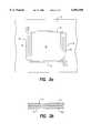
- FIG. 1ais an isometric view of a thermally-isolated microplatform that is supported by four microbeams above an underlying substrate, and is constructed in accord with the invention hereof.
- FIG. 1bis a sectional view of a microbeam of FIG. 1a.
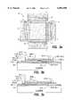
- FIG. 2ais a top view of a microplatform with an in situ electrical heater area and with two microbeams for support.
- the microbeamsprovide the desired upward-actuation of the microplatform and also serve as an electrical path for interconnects to the heater on the microplatform.
- FIG. 2bis a sectional view of a microbeam of FIG. 2a.
- FIG. 3ais a top view of a microplatform structure with a heater and four support microbeams.
- FIG. 3bis a sectional view of the microplatform structure of FIG. 3a, along line A-A'.
- FIG. 3cis a sectional view of the microplatform structure of FIG. 3a, along line B-B'.
- FIG. 4ais a top view of a microplatform with a retractable spiral microheater underneath.
- FIG. 4bis a top view of microplatform with a retractable microheater underneath, wherein the heater is shaped in serpentine segments.
- FIG. 4cis a side sectional view along line A-A' of the microplatform of FIGS. 4a and 4b, wherein the underlying heater is not powered and is in a relaxed position not touching the microplatform.
- FIG. 4dis a side sectional view along line A-A' of the microplatform of FIGS. 4a and 4b wherein the underlying heater is powered. The heater is thereby actuated upward, touching the microplatform and increasing the heat transfer from the heater into the microplatform.
- FIG. 5ais a top view of a bolometer cell, showing two support microbeams and underlying capacitor plates.
- FIG. 5bis a side sectional view of the bolometer cell of FIG. 5a, along line A-A', showing the cantilevered microplatform structure above the capacitor plates.
- the present inventioncomprises a microplatform that is supported in place by plural microbeams that are tethered to an underlying substrate.
- the process employed to fabricate the microplatformincludes a use of several layers of patterned thin films, one of which is a "sacrificial film", to be etched away near the end of processing, to enable the microplatform and portions of the support beams to be separated from the underlying substrate. Because the microbeams are comprised of layers exhibiting different TCEs and are fabricated at a temperature greater than the ambient at which the microplatform will be used, the release of the microbeams results in a flexure thereof and an elevation of the microplatform.
- microplatformFor applications where the microplatform is heated, as in micro-hotplates, there is a considerable heat conductivity path via the gas ambient from the microplatform into a lower temperature, underlying substrate. This conductivity path is approximately inversely proportional to the physical separation between the microplatform and the underlying substrate.
- the present inventionpermits an elevation of the microplatform permanently to heights of many micrometers above the underlying substrate, thereby increasing the thermal isolation of the microplatform in cases where gaseous thermal conduction is a substantial factor in permitting heat transfer from the microplatform.
- the increased separation between the microplatform and the underlying substrateis obtained by causing support microbeams to be comprised of patterned multimorph films.
- the microplatformtherefore is actuated to an elevated, static position immediately upon release from the substrate due to the mismatch in TCEs of the sandwiches of films in the patterned multimorph microbeams.
- a plurality of multimorph microbeams 10, 12, 14, and 16are tethered between a substrate 18 and a microplatform 20.
- the microbeamsself-actuate upward upon release of an underlying sacrificial layer and, without additional heating or cooling, act to elevate microplatform 20.
- This self-actuating to a static positionis accomplished by the use of microbeam structures comprising an upper layer (or layers) 22 that is deposited onto a lower layer (or layers) 24.
- Upper layer 22exhibits a higher TCE than lower layer 24 of the patterned microbeam.
- upper layer 22 of a microbeamis deposited at a temperature above the final operating ambient temperature of the microbeam (usually room temperature). For example, if upper layer 22 of the microbeam is deposited at a temperature of 200° C., then at room temperature upper layer 22 will be in tensile stress and will tend to cause the microbeam to bend in a concave-down direction, thereby causing the microplatforn to elevate upward, upon release.
- lower layer 24 of a microbeamis silicon dioxide
- examples of materials available for upper layer 22 that exhibit a higher TCEinclude: silicon nitride, polycrystalline silicon, titanium, aluminum and most metals.
- microbeamscan be fabricated of film materials possessed of minimum thermal conductivity (silicon dioxide and silicon nitride, typically).
- FIG. 2ashows a microplatform 30 supported by two microbeams 32 and 34 from substrate 35.
- Microbeams 32 and 34also provide electrically conducting paths 36, 38, respectively, for heating microplatform 30.
- each of microbeams 32 and 34(see FIG. 2b) comprises a patterned sandwich bimorph, with silicon dioxide as lower layer 40 and aluminum as upper layer 42.
- the resulting microbeam (32 or 34)will self-actuate upward if aluminum upper layer 42 has been deposited on lower layer 40 at an elevated temperature of 200° C.
- Microplatform 30is formed of sputtered tantalum silicide (and not heated to above 300° C.) that is supported on a silicon dioxide frame 44.
- the underlying sacrificial layer(not shown) is a polyimide which is sacrificed by an oxygen plasma release etch.
- Microplatform 30self-actuates upward following the sacrifice of the polyimide.
- Microplatform 30is heated to a desired temperature by controlling the voltage or current that is applied to the tantalum silicide microplatform 30. In fabrication of the structure of FIGS. 2a and 2b, the maximum process temperature is 300°.
- FIG. 3ashows a microplatform 50 with an integral heater layer 52 and four support microbeams 54, 56, 58 and 60, as one cell of a plurality of cells in an array.
- Microbeams 54 and 56each contain a metal interconnect 62, 64, respectively, for powering the heater layer 52.
- the other two microbeamscontain no conductive films and are used only for support and horizontal alignment of microplatform 50.
- FIG. 3ais an addressable cell and includes underlying patterned metal traces for row and column address lines (not shown). Each cell has connections to a row address trace and to a column address trace.
- the top view shown in FIG. 3aincludes support beams that are located outside (not underneath) microplatform 50. The support beams can also be positioned underneath microplatform 50, although the manufacturing complexity increases in such an arrangement.
- FIGS. 3b and 3care two sections of FIG. 3a, shown for clarity, FIG. 3b taken along line A-A' and FIG. 3c taken along line B-B'.
- Microplatform 50 of FIG. 3contains multiple films of materials patterned over a starting wafer of single crystal silicon which has been oxidized in an oxygen ambient to achieve a surface film of SiO 2 about 200 nanometers in thickness.
- the first metal (Metal-1)is aluminum that is sputtered on the oxidized silicon substrate at 200° C. and then patterned, using standard lithographic techniques.
- the first metalis then covered with a 300 nanometer film of silicon dioxide deposited using plasma-enhanced low pressure chemical vapor deposition (LPCVD) at 300° C.
- This resulting silicon dioxide film (PECVD SiO 2 -1)is patterned and followed by a second metal film of aluminum (Metal-2) that is sputtered and patterned in the same manner as the first metal film.
- the first and second metal filmsform the column and row address lines for the cell of FIG. 3 (which is part of a larger array).
- polyimideis spin coated on the wafer, baked, and patterned.
- the layer of polyimideis about 1000 nanometers in thickness and forms the layer to be sacrificed toward the end of the fabrication process.
- tantalum silicideis sputtered at a temperature of 250° C. and is patterned to form the resistive heater and to provide the structure for the microplatform area.
- a second layer of PECVD SiO 2is now deposited at 300° C. to form a dielectric insulating film over the tantalum silicide.
- a third film of aluminum (Metal-3)is sputtered at 200° C. and is patterned to form a reflecting mirror on the microplatform.
- the third film of aluminumalso forms the metal electrical interconnects on the microbeams between the address Metal-1 and Metal-2, which connect through the tantalum silicide resistive heater integral to the microplatform.
- Two of the support microbeamscontain the bimorph aluminum-silicon dioxide sandwich structure which causes the upward actuation of the microplatform, upon release.
- the two additional support microbeamsare bimorphs of silicon dioxide and aluminum also; they provide upward actuation of the microplatform also upon release but do not provide electrical interconnects. These additional two non-electrically conducting beams can be omitted if greater thermal isolation is required for the microplatform.
- the structured waferis subjected to an oxygen plasma etch at 200° C. for approximately one hour to remove the polyimide film and to release the microplatform upward.
- FIGS. 3a-3cThe cell structure shown in detail in FIGS. 3a-3c is typically replicated many times over on the supporting substrate wafer to form an addressable array.
- the underlying aluminum (Metal-1 and Metal-2) patterned films for array addressingare not required.
- FIGS. 4a-4dshow a further embodiment of the invention wherein the microplatform and support beam structure are constructed as shown in FIG. 1a, but with a heater derived in a different manner.
- the heateris a separate structure which underlies the microplatform. Upon being heated, the heater actuates upward to touch the microplatform, and upon cooling, the heater moves downward and away from the microplatform. In this manner, the microplatform can be heated quickly by direct thermal conduction when the hot heater touches the microplatform. When the heater structure cools and retracts downward, the thermal microplatform is isolated thermally and thus retains its temperature for a longer period of time.
- the cell shown in FIG. 4a-4dcan be constructed with very low thermal conductivity microbeams (e.g., silicon dioxide and silicon nitride) to support the microplatform.
- FIGS. 4a and 4bthe top view of the cell is shown and includes sufficient detail only to illustrate a microplatform 80 constructed with four low thermal conductance microbeams 82, 84, 86 and 88 which extend from tether points 90 to platform 80. Beneath microplatform 80, an underlying actuating heater element 92 is positioned out of contact therewith.
- FIG. 4ashows underlying heater element 92 in the form of a spiral which has been released from the substrate, and is tethered at two ends to the substrate.
- Heater element 92is formed of a multimorph (bimorph in this example) which actuates upward upon heating.
- the material layers in heater element 92comprise a top layer of lower TCE material, and a lower layer with a higher TCE.
- a top layer of PECVD SiO 2 and a lower layer of tantalum silicideare used for a preferred heater element 92.
- the lower silicide layerforms the electrical heater while the upper SiO 2 layer forms the necessary bimorph structure to cause upward movement of the heater element upon heating.
- a further preferred embodiment of heater element 92comprises an upper element of tantalum silicide and a lower layer of aluminum, separated by a thin dielectric layer of PECVD SiO 2 in a multimorph configuration.
- either layermay be used as the heater although the higher resistivity tantalum silicide layer is generally more suitable to the particular application.
- Two levels of sacrificial filmare used: one above and one below the actuated heater.
- FIG. 4bshows heater element 92 divided into multiple heater elements to provide control over the distribution of heating and/or to provide redundance in the heater element structure.
- FIG. 4cis a side sectional view of FIGS. 4a and 4b along line A-A', showing microplatform 80 overlying an unheated heater element 92.
- FIG. 4cshows that unheated heater element 92 is retracted and does not touch microplatform 80.
- FIG. 4dis a side sectional view of FIGS. 4a and 4b, taken along line A-A', showing the position of heater element 92 after being powered up to full temperature.
- the central position of its structureactuates upward and physically touches microplatform 80, thereby providing a thermal conduction path from heater element 92 into microplatform 80.
- heater element 92is cycled between conditions shown in FIG. 4c and FIG. 4d, in sequence.
- microplatform 80is insulated from the heat sink effect that would result if heater element 92 stayed in contact and cooled.
- microplatform 80is more fully thermally isolated following a heating event. If special care is used to construct the microbeams of low thermal conductivity materials, a high degree of thermal isolation can be obtained for microplatform 80.
- FIGS. 5a and 5billustrate the application of a microplatform to form a highly sensitive bolometer cell in which capacitance between two substrate capacitor plates change with the temperature of the microplatform.
- the microplatformis actuated upward by low thermal conductivity support beams upon release as described for FIG. 1.
- the microplatformfurther contains a multimorph (e.g., a bimorph of tantalum silicide and aluminum in a preferred embodiment) which hinges upward or downward with an increase in temperature or a decrease in temperature, respectively.
- FIG. 5ashows the top view of a bolometer cell containing two support beams 100, 102 securing a microplatform 104 so as to provide for a hinge-like movement along the left edge of microplatform 104.
- Microplatform 104 and untethered portions of support microbeams 100 and 103are released following the removal of a sacrificial polyimide film, using techniques discussed above for FIG. 3.
- Underlying microplatform 104is a split-capacitor electrode structure, fixed to the supporting substrate and including plates 106 and 108.
- the capacitance between connections 110 and 112 to the split electrode structurevaries as the microplatform hinges.
- An underlying layer of aluminum 114 on microplatform 104forms a covering plate for the capacitor.
- the overlying layer of microplatform 104is a layer of tantalum silicide 116, thereby rendering microplatform into a bimorph which deflects in response to heating events.
- the capacitance of the structure shown in FIG. 5is a sensitive function of the temperature of microplatform 104.
- FIG. 5bshows the side view section of FIG. 1a, taken along line A-A' in FIG. 5a, with microplatform 104 positioned by the support microbeams 100 and 102 to overlie the split capacitor electrodes 106 and 108 (that are electrically insulated from the substrate).
- This structurecan be constructed with an area varying from 10 nanometers by 10 nanometers up to 1 cm by 1 cm in size.
- the support microbeamscan actuate microplatform 104 upward to desired heights ranging from 1 micrometer to 1 millimeter.
Landscapes
- Micromachines (AREA)
Abstract
Description
This invention relates to micromachined semiconductor structures and, more particularly, to a thermally isolated microplatform that is rendered into position automatically during processing, upon elimination of a release layer.
The availability of micromachining technology has permitted the development of new classes of semiconductor-based microdevices for a variety of applications. Such technology, when based on batch processing with standard semiconductor clean room processes, often provides excellent economies in per unit cost and enhanced reliability for the end product. Micromachining provides the advantages of: design flexibility, ability to make structures of micron and submicron dimensions, batch fabrication at low cost, reliability, reproducibility, easy fabrication of arrays, ability to include control and signal conditioning electronics on a same substrate, and the use of a well established manufacturing infrastructure.
Micromachining with standard semiconductor processing techniques has been used to produce thermally isolated microplatforms which find a number of uses including: calorimetric gas detection, flow sensors, uncooled infra-red sensors, etc. The state of the art for thermally-isolated platforms is described by Manginell, Smith and Ricco in "An Overview of Micromachined Platforms for Thermal Sensing and Gas Detection", Proc. of the SPIE Conference on Smart Electronics and MEMS, Volume 3046, pages 273-383, March, 1997. Manginell et al. describe microplatforms that are suspended above substrate cavities and/or released by the sacrificial etching away of underlying film structures.
Fung et al. in "Thermal Analysis and Design of a Micro-Hotplate for Integrated Gas Sensor Applications" Proc. of the 8th Int;l Conf. on Solid-State Sensors and Actuators, Stockholm, Sweden, pages 818-821, 1995, describe a microhotplate for an integrated gas sensor application. Therein is described a heated microplatform that is thermally isolated from an underlying substrate by suspension microbeams and a micromachined underlying cavity space.
The various applications for thermally-isolated microplatforms are enhanced by controlling the rate of heating or cooling of a microplatform or microplatform array. A suspended microplatform derives thermal isolation from three phenomena which can either cool or heat the microplatform depending upon the specific structures. These phenomena are: radiation, convection, and conduction.
The total power P radiated per unit area of a microplatform is given by
P.sub.bb =K.sub.1 A.sub.bb T.sup.4
where k1 is a constant depending upon the specific surface of the microplatform, A is the effective platform area, and T is the temperature in absolute degrees. Thermal conduction can occur through a gaseous ambient and through thin film support microbeams. The total power conducted through the gaseous ambient or the microsupport beams is given by
P.sub.co =k.sub.2 A.sub.co (T.sub.2 -T.sub.1)
where k2 is a constant depending on the specific gas or solid-state film, Aco is the effective area cross section for heat flow, and (T1 -T2) is the differential temperature across which the heat conduction occurs.
The total power flowing away from the microplatform by convection is given by the expression
P.sub.cv =k.sub.3 A.sub.cv (T.sub.2 -T.sub.1)
where k3 is a constant depending upon the gas ambient and the surface of the microplatform, Acv is the effective area of the microplatform exposed to convection heat flow, and (T2 -T1) is the temperature differential between the surface of the microplatform and the ambient gas.
When a microplatform is positioned very close to an underlying substrate, there is a heat flow from the warmer structure to the cooler structure that is typically dominated by a combination of thermal conductivity and gas convective thermal transport. This heat flow decreases as the physical separation between the substrate and the microplatform increases. For microplatforms operating in a gas ambient (atmospheric gas pressure, for instance) substantial increases in thermal isolation of the microplatform can be obtained by increasing the distance between the microplatform and the underlying substrate.
When a support microbeam structure is specifically designed to greatly reduce the thermal conductivity through the microbeams, then increased height of the microplatform over a substrate has an even greater effect of increasing the thermal isolation of the microplatform.
For microplatforms designed for applications such as structural supports for bolometers and thermopiles, a maximum thermal isolation of the microplatform is usually desired so as to increase the sensitivity of the microplatform to incident radiation, generally in the infrared. A temperature sensor mounted on such a microplatform operates with maximum temperature sensitivity to incident radiation when the microsupport beams possess a minimum thermal conductivity. Also for such designs, the thermal isolation of the microplatform is increased further by increasing the separation between the microplatform and the underlying substrate.
A micromachined platform structure includes a substrate having a major surface and a platform positioned over the major surface. Plural support beams are tethered between the substrate and the platform, with each support beam including at least a first layer exhibiting a first thermal coefficient of expansion (TCE) and a second layer with a second TCE, the first TCE greater than the second TCE. The first layer is deposited on the second layer at a temperature that is higher than an ambient temperature at which the platform is to be used. Thus, at the ambient use temperature, the first layer is in a contraction/tension state relative to the second layer and causes a flexure of the support beams and an elevation of the platform away from the substrate's major surface.
FIG. 1a is an isometric view of a thermally-isolated microplatform that is supported by four microbeams above an underlying substrate, and is constructed in accord with the invention hereof.
FIG. 1b is a sectional view of a microbeam of FIG. 1a.
FIG. 2a is a top view of a microplatform with an in situ electrical heater area and with two microbeams for support. The microbeams provide the desired upward-actuation of the microplatform and also serve as an electrical path for interconnects to the heater on the microplatform.
FIG. 2b is a sectional view of a microbeam of FIG. 2a.
FIG. 3a is a top view of a microplatform structure with a heater and four support microbeams.
FIG. 3b is a sectional view of the microplatform structure of FIG. 3a, along line A-A'.
FIG. 3c is a sectional view of the microplatform structure of FIG. 3a, along line B-B'.
FIG. 4a is a top view of a microplatform with a retractable spiral microheater underneath.
FIG. 4b is a top view of microplatform with a retractable microheater underneath, wherein the heater is shaped in serpentine segments.
FIG. 4c is a side sectional view along line A-A' of the microplatform of FIGS. 4a and 4b, wherein the underlying heater is not powered and is in a relaxed position not touching the microplatform.
FIG. 4d is a side sectional view along line A-A' of the microplatform of FIGS. 4a and 4b wherein the underlying heater is powered. The heater is thereby actuated upward, touching the microplatform and increasing the heat transfer from the heater into the microplatform.
FIG. 5a is a top view of a bolometer cell, showing two support microbeams and underlying capacitor plates.
FIG. 5b is a side sectional view of the bolometer cell of FIG. 5a, along line A-A', showing the cantilevered microplatform structure above the capacitor plates.
The present invention comprises a microplatform that is supported in place by plural microbeams that are tethered to an underlying substrate. The process employed to fabricate the microplatform includes a use of several layers of patterned thin films, one of which is a "sacrificial film", to be etched away near the end of processing, to enable the microplatform and portions of the support beams to be separated from the underlying substrate. Because the microbeams are comprised of layers exhibiting different TCEs and are fabricated at a temperature greater than the ambient at which the microplatform will be used, the release of the microbeams results in a flexure thereof and an elevation of the microplatform.
This invention is related to an invention described in U.S. patent application Ser. No. 08/787,281, entitled: "Cantilevered Microstructure", filed Jan. 24, 1997. To elevate a microplatform therein, however, requires an application of heat to the microcantilevers so as to cause a flexure thereof. The disclosure of the aforementioned patent application is incorporated herein by reference.
For applications where the microplatform is heated, as in micro-hotplates, there is a considerable heat conductivity path via the gas ambient from the microplatform into a lower temperature, underlying substrate. This conductivity path is approximately inversely proportional to the physical separation between the microplatform and the underlying substrate. The present invention permits an elevation of the microplatform permanently to heights of many micrometers above the underlying substrate, thereby increasing the thermal isolation of the microplatform in cases where gaseous thermal conduction is a substantial factor in permitting heat transfer from the microplatform.
Even for cases where a thermally isolated microplatform is operated in a partial vacuum, there can be substantial gaseous thermal conductivity between the microplatform and the underlying substrate. In such a case, there is an advantage in using the present invention as a means of increasing the path for thermal conduction by elevating the microplatform (via released microbeams which actuate upward).
In the present invention the increased separation between the microplatform and the underlying substrate is obtained by causing support microbeams to be comprised of patterned multimorph films. The microplatform therefore is actuated to an elevated, static position immediately upon release from the substrate due to the mismatch in TCEs of the sandwiches of films in the patterned multimorph microbeams.
Referring to FIGS. 1a and 1b, a plurality of multimorph microbeams 10, 12, 14, and 16 are tethered between asubstrate 18 and amicroplatform 20. The microbeams self-actuate upward upon release of an underlying sacrificial layer and, without additional heating or cooling, act to elevatemicroplatform 20. This self-actuating to a static position is accomplished by the use of microbeam structures comprising an upper layer (or layers) 22 that is deposited onto a lower layer (or layers) 24.Upper layer 22 exhibits a higher TCE thanlower layer 24 of the patterned microbeam.
During the fabrication process,upper layer 22 of a microbeam is deposited at a temperature above the final operating ambient temperature of the microbeam (usually room temperature). For example, ifupper layer 22 of the microbeam is deposited at a temperature of 200° C., then at room temperatureupper layer 22 will be in tensile stress and will tend to cause the microbeam to bend in a concave-down direction, thereby causing the microplatforn to elevate upward, upon release.
Iflower layer 24 of a microbeam is silicon dioxide, then examples of materials available forupper layer 22 that exhibit a higher TCE include: silicon nitride, polycrystalline silicon, titanium, aluminum and most metals.
If there are no electrical connections betweenmicroplatform 20 and structures onsubstrate 18, the microbeams can be fabricated of film materials possessed of minimum thermal conductivity (silicon dioxide and silicon nitride, typically).
The example of FIG. 2a shows amicroplatform 30 supported by two microbeams 32 and 34 fromsubstrate 35. Microbeams 32 and 34 also provide electrically conductingpaths heating microplatform 30. In this embodiment, each ofmicrobeams 32 and 34 (see FIG. 2b) comprises a patterned sandwich bimorph, with silicon dioxide aslower layer 40 and aluminum asupper layer 42. The resulting microbeam (32 or 34) will self-actuate upward if aluminumupper layer 42 has been deposited onlower layer 40 at an elevated temperature of 200° C.
FIG. 3a shows amicroplatform 50 with anintegral heater layer 52 and foursupport microbeams metal interconnect 62, 64, respectively, for powering theheater layer 52. The other two microbeams contain no conductive films and are used only for support and horizontal alignment ofmicroplatform 50.
The structure shown in FIG. 3a is an addressable cell and includes underlying patterned metal traces for row and column address lines (not shown). Each cell has connections to a row address trace and to a column address trace. The top view shown in FIG. 3a includes support beams that are located outside (not underneath)microplatform 50. The support beams can also be positioned underneathmicroplatform 50, although the manufacturing complexity increases in such an arrangement. FIGS. 3b and 3c are two sections of FIG. 3a, shown for clarity, FIG. 3b taken along line A-A' and FIG. 3c taken along line B-B'.
Next, polyimide is spin coated on the wafer, baked, and patterned. The layer of polyimide is about 1000 nanometers in thickness and forms the layer to be sacrificed toward the end of the fabrication process. Next tantalum silicide is sputtered at a temperature of 250° C. and is patterned to form the resistive heater and to provide the structure for the microplatform area. A second layer of PECVD SiO2 is now deposited at 300° C. to form a dielectric insulating film over the tantalum silicide. Finally, a third film of aluminum (Metal-3) is sputtered at 200° C. and is patterned to form a reflecting mirror on the microplatform. The third film of aluminum also forms the metal electrical interconnects on the microbeams between the address Metal-1 and Metal-2, which connect through the tantalum silicide resistive heater integral to the microplatform.
Two of the support microbeams contain the bimorph aluminum-silicon dioxide sandwich structure which causes the upward actuation of the microplatform, upon release. The two additional support microbeams are bimorphs of silicon dioxide and aluminum also; they provide upward actuation of the microplatform also upon release but do not provide electrical interconnects. These additional two non-electrically conducting beams can be omitted if greater thermal isolation is required for the microplatform.
Next, the structured wafer is subjected to an oxygen plasma etch at 200° C. for approximately one hour to remove the polyimide film and to release the microplatform upward.
The cell structure shown in detail in FIGS. 3a-3c is typically replicated many times over on the supporting substrate wafer to form an addressable array. For structures in which only a single cell is required, such as a thermopile discrete infrared detector, the underlying aluminum (Metal-1 and Metal-2) patterned films for array addressing are not required.
FIGS. 4a-4d show a further embodiment of the invention wherein the microplatform and support beam structure are constructed as shown in FIG. 1a, but with a heater derived in a different manner. In this embodiment, the heater is a separate structure which underlies the microplatform. Upon being heated, the heater actuates upward to touch the microplatform, and upon cooling, the heater moves downward and away from the microplatform. In this manner, the microplatform can be heated quickly by direct thermal conduction when the hot heater touches the microplatform. When the heater structure cools and retracts downward, the thermal microplatform is isolated thermally and thus retains its temperature for a longer period of time. The cell shown in FIG. 4a-4d can be constructed with very low thermal conductivity microbeams (e.g., silicon dioxide and silicon nitride) to support the microplatform.
In FIGS. 4a and 4b the top view of the cell is shown and includes sufficient detail only to illustrate amicroplatform 80 constructed with four lowthermal conductance microbeams tether points 90 toplatform 80. Beneathmicroplatform 80, an underlyingactuating heater element 92 is positioned out of contact therewith.
FIG. 4a showsunderlying heater element 92 in the form of a spiral which has been released from the substrate, and is tethered at two ends to the substrate.Heater element 92 is formed of a multimorph (bimorph in this example) which actuates upward upon heating. The material layers inheater element 92 comprise a top layer of lower TCE material, and a lower layer with a higher TCE. For apreferred heater element 92, a top layer of PECVD SiO2 and a lower layer of tantalum silicide are used. The lower silicide layer forms the electrical heater while the upper SiO2 layer forms the necessary bimorph structure to cause upward movement of the heater element upon heating. A further preferred embodiment ofheater element 92 comprises an upper element of tantalum silicide and a lower layer of aluminum, separated by a thin dielectric layer of PECVD SiO2 in a multimorph configuration. In the latter case, either layer may be used as the heater although the higher resistivity tantalum silicide layer is generally more suitable to the particular application. Two levels of sacrificial film are used: one above and one below the actuated heater.
FIG. 4b showsheater element 92 divided into multiple heater elements to provide control over the distribution of heating and/or to provide redundance in the heater element structure.
FIG. 4c is a side sectional view of FIGS. 4a and 4b along line A-A', showingmicroplatform 80 overlying anunheated heater element 92. FIG. 4c shows thatunheated heater element 92 is retracted and does not touchmicroplatform 80.
FIG. 4d is a side sectional view of FIGS. 4a and 4b, taken along line A-A', showing the position ofheater element 92 after being powered up to full temperature. When the temperature ofheater element 92 increases, the central position of its structure actuates upward and physically touchesmicroplatform 80, thereby providing a thermal conduction path fromheater element 92 intomicroplatform 80.
In operation,heater element 92 is cycled between conditions shown in FIG. 4c and FIG. 4d, in sequence. Whenheater element 92 is retracted following a heating event,microplatform 80 is insulated from the heat sink effect that would result ifheater element 92 stayed in contact and cooled. Thus microplatform 80 is more fully thermally isolated following a heating event. If special care is used to construct the microbeams of low thermal conductivity materials, a high degree of thermal isolation can be obtained formicroplatform 80.
FIGS. 5a and 5b illustrate the application of a microplatform to form a highly sensitive bolometer cell in which capacitance between two substrate capacitor plates change with the temperature of the microplatform. In this case the microplatform is actuated upward by low thermal conductivity support beams upon release as described for FIG. 1. The microplatform further contains a multimorph (e.g., a bimorph of tantalum silicide and aluminum in a preferred embodiment) which hinges upward or downward with an increase in temperature or a decrease in temperature, respectively.
FIG. 5a shows the top view of a bolometer cell containing twosupport beams microplatform 104 so as to provide for a hinge-like movement along the left edge ofmicroplatform 104.Microplatform 104 and untethered portions ofsupport microbeams 100 and 103 are released following the removal of a sacrificial polyimide film, using techniques discussed above for FIG. 3.
Underlyingmicroplatform 104 is a split-capacitor electrode structure, fixed to the supporting substrate and includingplates 106 and 108. The capacitance betweenconnections aluminum 114 onmicroplatform 104 forms a covering plate for the capacitor. The overlying layer ofmicroplatform 104 is a layer oftantalum silicide 116, thereby rendering microplatform into a bimorph which deflects in response to heating events. Thus, the capacitance of the structure shown in FIG. 5 is a sensitive function of the temperature ofmicroplatform 104.
FIG. 5b shows the side view section of FIG. 1a, taken along line A-A' in FIG. 5a, withmicroplatform 104 positioned by the support microbeams 100 and 102 to overlie the split capacitor electrodes 106 and 108 (that are electrically insulated from the substrate). This structure can be constructed with an area varying from 10 nanometers by 10 nanometers up to 1 cm by 1 cm in size. The support microbeams can actuatemicroplatform 104 upward to desired heights ranging from 1 micrometer to 1 millimeter.
It should be understood that the foregoing description is only illustrative of the invention. Various alternatives and modifications can be devised by those skilled in the art without departing from the invention. Accordingly, the present invention is intended to embrace all such alternatives, modifications and variances which fall within the scope of the appended claims.
Claims (13)
1. A micromachined platform structure comprising:
a substrate having a major surface;
a platform positioned away from said major surface;
plural support beams tethered between said substrate and said platform, each said support beam comprising at least a first layer exhibiting a first thermal coefficient of expansion (TCE) and a second layer with a second TCE, said first TCE greater than said second TCE, said first layer deposited on said second layer at a temperature that is higher than an ambient temperature at which said platform is to be used, said first layer, at said ambient temperature, having contracted and in tension relative to said second layer, causing a flexure of said beam to elevate said platform to a static position away from said major surface.
2. The micromachined platform structure as recited in claim 1, wherein said first layer and second layer of at least some of said plural support beams are both insulating materials.
3. The micromachined platform structure as recited in claim 1, wherein said platform comprises a resistive heater element and wherein at least one of said first layer or said second layer of at least some of said plural support beams is a conductor material which enables application of a heater current to said resistive heater element.
4. The micromachined platform structure as recited in claim 1, further comprising:
a heater structure positioned between said substrate and said platform and comprising plural layers exhibiting different TCEs, said heater structure responsive to an applied heater current to deflect into contact with said platform and thereby provide a heating thereof.
5. The micromachined platform structure as recited in claim 4 wherein said heater structure retracts away from said platform upon cooling to enable increased thermal isolation of said platform and a decreased rate of cooling thereof.
6. The micromachined platform structure as recited in claim 5, wherein said heater structure comprises a plurality of independently controllable heater elements.
7. The micromachined platform structure as recited in claim 5, wherein said heater structure comprises a spiral structure.
8. A micromachined platform structure comprising:
a substrate having a major surface;
capacitive plate means formed on said substrate;
a platform positioned away from said major surface and comprising plural layers exhibiting different thermal coefficients of expansion (TCEs), at least one of said layers comprising a conductive material, said platform responsive to applied heat to move with respect to said capacitive plate means on said substrate;
plural support beams tethered between said substrate and said platform, each said support beam comprising at least a first layer exhibiting a first TCE and a second layer with a second TCE, said first TCE greater than said second TCE,
said first layer deposited on said second layer at a temperature that is higher than an ambient temperature at which said platform is to be used, said first layer, at said ambient temperature, having contracted and in tension relative to said second layer, causing a flexure of said beam to elevate said platform away from said major surface; and
means for sensing changes in capacitance between said capacitive plate means and said conductive material of said platform as an indication of a change of temperature of said platform.
9. The micromachined platform structure as recited in claim 8, wherein said capacitive plate means comprise a pair of plates and said conductive material of said platform is positioned to substantially cover said pair of plates.
10. The micromachined platform structure as recited in claim 8, wherein said first layer and said second layer of said plural support beams are low thermal conductance materials.
11. A method for configuring a micromachined platform structure, said structure including a substrate having a major surface, a platform positioned upon a sacrificial material on said major surface and plural support beams tethered between said substrate and said platform, each support beam comprising at least a first layer exhibiting a first thermal coefficient of expansion (TCE) and a second layer with a second TCE, said first TCE greater than said second TCE, said method comprising the steps of:
depositing said first layer on said second layer at a temperature that is higher than an ambient temperature at which said platform is to be used, said first layer thus being in tension at said ambient temperature;
removing said sacrificial layer to enable, at said ambient temperature, said first layer to cause a flexure of said support beams to elevate said platform to a static position away from said major surface.
12. The method as recited in claim 11 wherein a heater structure is positioned between said substrate and said platform, said heater structure comprising plural layers exhibiting different TCEs, said method comprising the further step of:
applying a heater current said heater structure to deflect said heater structure into contact with said platform to thereby provide a heating thereof.
13. A method for configuring a micromachined platform structure that includes a substrate having a major surface, capacitive plate means formed on said substrate, a platform positioned on a sacrificial layer attached to said substrate, said platform comprising plural layers exhibiting different thermal coefficients of expansion (TCEs), at least one of said layers comprising a conductive material, said platform responsive to applied heat to move with respect to said capacitive plate means on said substrate, and plural support beams tethered between said substrate and said platform, each said support beam comprising at least a first layer exhibiting a first TCE and a second layer with a second TCE, said first TCE greater than said second TCE, said method comprising the steps of:
depositing said first layer on said second layer at a temperature that is higher than an ambient temperature at which said platform is to be used, said first layer thus being in tension at said ambient temperature;
removing said sacrificial layer to enable, at said ambient temperature, said first layer to cause a flexure of said support beams to elevate said platform to a static position away from said major surface; and
sensing changes in capacitance between said capacitive plate means and said conductive material of said platform as an indication of a change of temperature of said platform.
Priority Applications (1)
| Application Number | Priority Date | Filing Date | Title |
|---|---|---|---|
| US08/972,055US6091050A (en) | 1997-11-17 | 1997-11-17 | Thermal microplatform |
Applications Claiming Priority (1)
| Application Number | Priority Date | Filing Date | Title |
|---|---|---|---|
| US08/972,055US6091050A (en) | 1997-11-17 | 1997-11-17 | Thermal microplatform |
Publications (1)
| Publication Number | Publication Date |
|---|---|
| US6091050Atrue US6091050A (en) | 2000-07-18 |
Family
ID=25519105
Family Applications (1)
| Application Number | Title | Priority Date | Filing Date |
|---|---|---|---|
| US08/972,055Expired - Fee RelatedUS6091050A (en) | 1997-11-17 | 1997-11-17 | Thermal microplatform |
Country Status (1)
| Country | Link |
|---|---|
| US (1) | US6091050A (en) |
Cited By (52)
| Publication number | Priority date | Publication date | Assignee | Title |
|---|---|---|---|---|
| US6300665B1 (en)* | 2000-09-28 | 2001-10-09 | Xerox Corporation | Structure for an optical switch on a silicon on insulator substrate |
| WO2002080620A1 (en)* | 2001-03-28 | 2002-10-10 | Ecole Polytechnique Federale De Lausanne (Epfl) | High temperature micro-hotplate |
| US6466356B1 (en)* | 2000-09-28 | 2002-10-15 | Xerox Corporation | Structure for an optical switch on a silicon substrate |
| US6501588B1 (en)* | 2000-09-28 | 2002-12-31 | Xerox Corporation | Method for an optical switch on a silicon substrate |
| US6504643B1 (en)* | 2000-09-28 | 2003-01-07 | Xerox Corporation | Structure for an optical switch on a substrate |
| EP1193523A3 (en)* | 2000-09-28 | 2003-05-07 | Xerox Corporation | Micro-electro-mechanical mirror structure |
| US6566725B1 (en)* | 1999-07-30 | 2003-05-20 | Xactix, Inc. | Thermal isolation using vertical structures |
| US6583416B1 (en)* | 1999-11-15 | 2003-06-24 | Sarnoff Corporation | Uncooled IR detector array having improved temperature stability and reduced fixed pattern noise |
| US6633260B2 (en) | 2001-10-05 | 2003-10-14 | Ball Aerospace & Technologies Corp. | Electromechanical switching for circuits constructed with flexible materials |
| WO2003034457A3 (en)* | 2001-10-18 | 2003-10-16 | Univ Illinois | High cycle mems device |
| US6657764B1 (en)* | 1999-03-18 | 2003-12-02 | The Trustees Of Boston University | Very large angle integrated optical scanner made with an array of piezoelectric monomorphs |
| US20030233862A1 (en)* | 2002-05-13 | 2003-12-25 | Wise Kensall D. | Separation microcolumn assembly for a microgas chromatograph and the like |
| US6717496B2 (en) | 2001-11-13 | 2004-04-06 | The Board Of Trustees Of The University Of Illinois | Electromagnetic energy controlled low actuation voltage microelectromechanical switch |
| US20040147056A1 (en)* | 2003-01-29 | 2004-07-29 | Mckinnell James C. | Micro-fabricated device and method of making |
| US6770882B2 (en) | 2002-01-14 | 2004-08-03 | Multispectral Imaging, Inc. | Micromachined pyro-optical structure |
| US20040195510A1 (en)* | 2003-02-07 | 2004-10-07 | Carr William N. | Radiation sensor with synchronous reset |
| US20040232337A1 (en)* | 2001-06-28 | 2004-11-25 | Michel Vilain | Microbolometer and method for making same |
| US20040255643A1 (en)* | 2003-05-13 | 2004-12-23 | Wise Kensall D. | High-performance separation microcolumn assembly and method of making same |
| US20050109940A1 (en)* | 2003-11-25 | 2005-05-26 | Carr William N. | Radiation sensor |
| US6998946B2 (en) | 2002-09-17 | 2006-02-14 | The Board Of Trustees Of The University Of Illinois | High cycle deflection beam MEMS devices |
| US20060038103A1 (en)* | 2002-11-08 | 2006-02-23 | Helmbrecht Micheal A | Deformable mirror method including bimorph flexures |
| US20070215447A1 (en)* | 2004-04-06 | 2007-09-20 | Commissariat A L'energie Atomique | Low Consumption and Low Actuation Voltage Microswitch |
| US20070249082A1 (en)* | 2006-02-03 | 2007-10-25 | Hitachi, Ltd. | Manufacturing method of MEMS structures and manufacturing method of MEMS structures with semiconductor device |
| US20080101748A1 (en)* | 2006-10-26 | 2008-05-01 | Hewlett-Packard Development Company Lp | Mems device lever |
| US20080151426A1 (en)* | 2006-12-20 | 2008-06-26 | Fu-Ying Huang | System and method for compliant, adaptive hard drive sliders |
| US7471441B1 (en) | 2006-06-09 | 2008-12-30 | Hewlett-Packard Development Company, L.P. | Flexures |
| US20090020522A1 (en)* | 2007-07-16 | 2009-01-22 | Samsung Electronics Co., Ltd. | Micro-heaters and methods for manufacturing the same |
| US20090020760A1 (en)* | 2007-07-16 | 2009-01-22 | Samsung Electronics Co., Ltd. | Methods for forming materials using micro-heaters and electronic devices including such materials |
| US20090139974A1 (en)* | 2007-11-30 | 2009-06-04 | Samsung Electronics Co., Ltd. | Micro-heaters, micro-heater arrays, methods for manufacturing the same and electronic devices using the same |
| US20090261688A1 (en)* | 2005-04-15 | 2009-10-22 | University Of Florida Research Foundation, Inc. | Microactuator having multiple degrees of freedom |
| US20090289049A1 (en)* | 2008-05-23 | 2009-11-26 | Samsung Electronics Co., Ltd. | Micro-heaters and methods of manufacturing the same |
| US7629725B1 (en) | 2002-11-08 | 2009-12-08 | Iris Ao, Inc. | Micromechanical actuator with asymmetrically shaped electrodes |
| US20090304371A1 (en)* | 2008-06-10 | 2009-12-10 | Samsung Electronics Co., Ltd. | MIcro-heaters, methods for manufacturing the same, and methods for forming patterns using the micro-heaters |
| US20100192941A1 (en)* | 2009-01-30 | 2010-08-05 | Stoia Michael F | Solar Concentration System With Micro-Mirror Array |
| US8143578B2 (en) | 2009-04-21 | 2012-03-27 | The United States Of America As Represented By The Secretary Of The Army | Ferroelectric radiation detector employing frequency modulated readout |
| CN103246059A (en)* | 2012-02-14 | 2013-08-14 | 富士胶片株式会社 | Mirror driving device and method of controlling the device |
| CN103274349A (en)* | 2013-04-26 | 2013-09-04 | 北京大学 | Thermal stress insulating MEMS micro heater interconnected substrate and method for manufacturing thermal stress insulating MEMS micro heater interconnected substrate |
| WO2014077917A1 (en)* | 2012-11-19 | 2014-05-22 | Intelligent Energy, Inc. | A hydrogen generator having a thermal actuator |
| US8979954B2 (en) | 2011-04-21 | 2015-03-17 | Intelligent Energy Limited | Hydrogen generator with improved volume efficiency |
| US8994556B2 (en) | 2012-05-24 | 2015-03-31 | Douglas H. Lundy | Threat detection system and method |
| US20150253212A1 (en)* | 2014-03-05 | 2015-09-10 | Kabushiki Kaisha Toshiba | Mems device |
| US20150321900A1 (en)* | 2014-05-06 | 2015-11-12 | Mems Drive, Inc. | Low stiffness flexure |
| US9725316B2 (en) | 2013-03-07 | 2017-08-08 | Intelligent Energy Inc. | Hydrogen generator with replaceable fuel unit and a method of producing hydrogen gas |
| US9813022B2 (en) | 2014-02-21 | 2017-11-07 | The Boeing Company | Dynamically setting a threshold output level for a solar array |
| US20170359003A1 (en)* | 2016-06-14 | 2017-12-14 | Mems Drive, Inc. | Electric connection flexures |
| US10093538B2 (en) | 2012-11-19 | 2018-10-09 | Intelligent Energy Inc. | Heater assembly, hydrogen generator and method of providing hydrogen gas |
| US10236822B2 (en) | 2014-02-21 | 2019-03-19 | The Boeing Company | Method and apparatus for calibrating a micro-concentrator solar array |
| US10244171B2 (en) | 2014-05-06 | 2019-03-26 | Mems Drive, Inc. | Electrical bar latching for low stiffness flexure MEMS actuator |
| US10250182B2 (en) | 2014-02-21 | 2019-04-02 | The Boeing Company | Micro-concentrator solar array using micro-electromechanical systems (MEMS) based reflectors |
| US10693028B2 (en) | 2014-02-21 | 2020-06-23 | The Boeing Company | Micro-concentrator solar array using micro-electromechanical systems (MEMS) based reflectors |
| US10852263B2 (en)* | 2017-11-08 | 2020-12-01 | Stmicroelectronics S.R.L. | Micro-heater element for a microelectromechanical sensor device and corresponding microelectromechanical sensor device |
| WO2021144464A1 (en)* | 2020-01-15 | 2021-07-22 | 4K-Mems Sàrl | Metrology device, system and method |
Citations (12)
| Publication number | Priority date | Publication date | Assignee | Title |
|---|---|---|---|---|
| US4556050A (en)* | 1984-05-02 | 1985-12-03 | Hodgson Darel E | Artificial sphincter including a shape memory member |
| US4736629A (en)* | 1985-12-20 | 1988-04-12 | Silicon Designs, Inc. | Micro-miniature accelerometer |
| US5058856A (en)* | 1991-05-08 | 1991-10-22 | Hewlett-Packard Company | Thermally-actuated microminiature valve |
| US5140155A (en)* | 1990-10-17 | 1992-08-18 | Edjewise Sensor Products, Inc. | Fiber optic sensor with dual condition-responsive beams |
| US5295206A (en)* | 1992-10-05 | 1994-03-15 | Metatech Corporation | Fiberoptic temperature transducer |
| US5475318A (en)* | 1993-10-29 | 1995-12-12 | Robert B. Marcus | Microprobe |
| US5536963A (en)* | 1994-05-11 | 1996-07-16 | Regents Of The University Of Minnesota | Microdevice with ferroelectric for sensing or applying a force |
| US5626779A (en)* | 1993-06-07 | 1997-05-06 | Nec Corporation | Micromachine transducer with cantilevered movable portion |
| US5635750A (en)* | 1994-10-18 | 1997-06-03 | Siemens Aktiengesellschaft | Micromechanical relay with transverse slots |
| US5659195A (en)* | 1995-06-08 | 1997-08-19 | The Regents Of The University Of California | CMOS integrated microsensor with a precision measurement circuit |
| US5796152A (en)* | 1997-01-24 | 1998-08-18 | Roxburgh Ltd. | Cantilevered microstructure |
| US5810325A (en)* | 1996-06-25 | 1998-09-22 | Bcam International, Inc. | Microvalve |
- 1997
- 1997-11-17USUS08/972,055patent/US6091050A/ennot_activeExpired - Fee Related
Patent Citations (12)
| Publication number | Priority date | Publication date | Assignee | Title |
|---|---|---|---|---|
| US4556050A (en)* | 1984-05-02 | 1985-12-03 | Hodgson Darel E | Artificial sphincter including a shape memory member |
| US4736629A (en)* | 1985-12-20 | 1988-04-12 | Silicon Designs, Inc. | Micro-miniature accelerometer |
| US5140155A (en)* | 1990-10-17 | 1992-08-18 | Edjewise Sensor Products, Inc. | Fiber optic sensor with dual condition-responsive beams |
| US5058856A (en)* | 1991-05-08 | 1991-10-22 | Hewlett-Packard Company | Thermally-actuated microminiature valve |
| US5295206A (en)* | 1992-10-05 | 1994-03-15 | Metatech Corporation | Fiberoptic temperature transducer |
| US5626779A (en)* | 1993-06-07 | 1997-05-06 | Nec Corporation | Micromachine transducer with cantilevered movable portion |
| US5475318A (en)* | 1993-10-29 | 1995-12-12 | Robert B. Marcus | Microprobe |
| US5536963A (en)* | 1994-05-11 | 1996-07-16 | Regents Of The University Of Minnesota | Microdevice with ferroelectric for sensing or applying a force |
| US5635750A (en)* | 1994-10-18 | 1997-06-03 | Siemens Aktiengesellschaft | Micromechanical relay with transverse slots |
| US5659195A (en)* | 1995-06-08 | 1997-08-19 | The Regents Of The University Of California | CMOS integrated microsensor with a precision measurement circuit |
| US5810325A (en)* | 1996-06-25 | 1998-09-22 | Bcam International, Inc. | Microvalve |
| US5796152A (en)* | 1997-01-24 | 1998-08-18 | Roxburgh Ltd. | Cantilevered microstructure |
Non-Patent Citations (4)
| Title |
|---|
| Proceedings of SPIE, Smart Structures and Meterials 1997, vol. 3046, pp. 273 283, Manginell et al., An Overview of Micromachined Platforms for Thermal Sensing and Gas Detection .* |
| Proceedings of SPIE, Smart Structures and Meterials 1997, vol. 3046, pp. 273-283, Manginell et al., "An Overview of Micromachined Platforms for Thermal Sensing and Gas Detection". |
| The 8th Internat l Conference on Solid State Sensors and Actuators and Eurosensors IX Digest of Technical Papers, pp. 818 821, Jun. 25 29, 1995, vol. 2, Fung et al., Thermal Analysis and Design of a Micro Hotplate for Integrated Gas Sensor Applications .* |
| The 8th Internat'l Conference on Solid-State Sensors and Actuators and Eurosensors IX-Digest of Technical Papers, pp. 818-821, Jun. 25-29, 1995, vol. 2, Fung et al., "Thermal Analysis and Design of a Micro-Hotplate for Integrated Gas Sensor Applications". |
Cited By (81)
| Publication number | Priority date | Publication date | Assignee | Title |
|---|---|---|---|---|
| US6657764B1 (en)* | 1999-03-18 | 2003-12-02 | The Trustees Of Boston University | Very large angle integrated optical scanner made with an array of piezoelectric monomorphs |
| US6566725B1 (en)* | 1999-07-30 | 2003-05-20 | Xactix, Inc. | Thermal isolation using vertical structures |
| US6653239B2 (en) | 1999-07-30 | 2003-11-25 | Xactix, Inc. | Thermal isolation using vertical structures |
| US6583416B1 (en)* | 1999-11-15 | 2003-06-24 | Sarnoff Corporation | Uncooled IR detector array having improved temperature stability and reduced fixed pattern noise |
| EP1193524A3 (en)* | 2000-09-28 | 2003-05-07 | Xerox Corporation | Micro-electro-mechanical mirror structure |
| US6504643B1 (en)* | 2000-09-28 | 2003-01-07 | Xerox Corporation | Structure for an optical switch on a substrate |
| EP1193522A3 (en)* | 2000-09-28 | 2003-05-07 | Xerox Corporation | Micro-electro-mechanical mirror structure manufacture |
| EP1193523A3 (en)* | 2000-09-28 | 2003-05-07 | Xerox Corporation | Micro-electro-mechanical mirror structure |
| US6300665B1 (en)* | 2000-09-28 | 2001-10-09 | Xerox Corporation | Structure for an optical switch on a silicon on insulator substrate |
| US6501588B1 (en)* | 2000-09-28 | 2002-12-31 | Xerox Corporation | Method for an optical switch on a silicon substrate |
| US6466356B1 (en)* | 2000-09-28 | 2002-10-15 | Xerox Corporation | Structure for an optical switch on a silicon substrate |
| EP1193526A1 (en)* | 2000-09-28 | 2002-04-03 | Xerox Corporation | Mirror structure |
| WO2002080620A1 (en)* | 2001-03-28 | 2002-10-10 | Ecole Polytechnique Federale De Lausanne (Epfl) | High temperature micro-hotplate |
| US7241998B2 (en)* | 2001-06-28 | 2007-07-10 | Commissariat A L'energie Atomique | Microbolometer and its manufacturing method |
| US20040232337A1 (en)* | 2001-06-28 | 2004-11-25 | Michel Vilain | Microbolometer and method for making same |
| US6633260B2 (en) | 2001-10-05 | 2003-10-14 | Ball Aerospace & Technologies Corp. | Electromechanical switching for circuits constructed with flexible materials |
| US20040008099A1 (en)* | 2001-10-18 | 2004-01-15 | The Board Of Trustees Of The University Of Illinois | High cycle MEMS device |
| US6919784B2 (en)* | 2001-10-18 | 2005-07-19 | The Board Of Trustees Of The University Of Illinois | High cycle MEMS device |
| WO2003034457A3 (en)* | 2001-10-18 | 2003-10-16 | Univ Illinois | High cycle mems device |
| US7142076B2 (en) | 2001-10-18 | 2006-11-28 | The Board Of Trustees Of The University Of Illinois | High cycle MEMS device |
| US6717496B2 (en) | 2001-11-13 | 2004-04-06 | The Board Of Trustees Of The University Of Illinois | Electromagnetic energy controlled low actuation voltage microelectromechanical switch |
| US6770882B2 (en) | 2002-01-14 | 2004-08-03 | Multispectral Imaging, Inc. | Micromachined pyro-optical structure |
| US20030233862A1 (en)* | 2002-05-13 | 2003-12-25 | Wise Kensall D. | Separation microcolumn assembly for a microgas chromatograph and the like |
| US6838640B2 (en)* | 2002-05-13 | 2005-01-04 | The Regents Of The University Of Michigan | Separation microcolumn assembly for a microgas chromatograph and the like |
| US6998946B2 (en) | 2002-09-17 | 2006-02-14 | The Board Of Trustees Of The University Of Illinois | High cycle deflection beam MEMS devices |
| US7741685B1 (en) | 2002-11-08 | 2010-06-22 | Iris Ao, Inc. | Method and apparatus for an actuator system having buried interconnect lines |
| US20060038103A1 (en)* | 2002-11-08 | 2006-02-23 | Helmbrecht Micheal A | Deformable mirror method including bimorph flexures |
| US7699296B1 (en) | 2002-11-08 | 2010-04-20 | Iris Ao, Inc. | Method and apparatus for an actuator having an intermediate frame |
| US7629725B1 (en) | 2002-11-08 | 2009-12-08 | Iris Ao, Inc. | Micromechanical actuator with asymmetrically shaped electrodes |
| US20040147056A1 (en)* | 2003-01-29 | 2004-07-29 | Mckinnell James C. | Micro-fabricated device and method of making |
| US20040195510A1 (en)* | 2003-02-07 | 2004-10-07 | Carr William N. | Radiation sensor with synchronous reset |
| US20040255643A1 (en)* | 2003-05-13 | 2004-12-23 | Wise Kensall D. | High-performance separation microcolumn assembly and method of making same |
| US20050109940A1 (en)* | 2003-11-25 | 2005-05-26 | Carr William N. | Radiation sensor |
| US7782170B2 (en)* | 2004-04-06 | 2010-08-24 | Commissariat A L'energie Atomique | Low consumption and low actuation voltage microswitch |
| US20070215447A1 (en)* | 2004-04-06 | 2007-09-20 | Commissariat A L'energie Atomique | Low Consumption and Low Actuation Voltage Microswitch |
| US8148874B2 (en)* | 2005-04-15 | 2012-04-03 | University Of Florida Research Foundation, Inc. | Microactuator having multiple degrees of freedom |
| US20090261688A1 (en)* | 2005-04-15 | 2009-10-22 | University Of Florida Research Foundation, Inc. | Microactuator having multiple degrees of freedom |
| US20070249082A1 (en)* | 2006-02-03 | 2007-10-25 | Hitachi, Ltd. | Manufacturing method of MEMS structures and manufacturing method of MEMS structures with semiconductor device |
| US7670861B2 (en)* | 2006-02-03 | 2010-03-02 | Hitachi, Ltd. | Controlling stress in MEMS structures |
| US7471441B1 (en) | 2006-06-09 | 2008-12-30 | Hewlett-Packard Development Company, L.P. | Flexures |
| US20080101748A1 (en)* | 2006-10-26 | 2008-05-01 | Hewlett-Packard Development Company Lp | Mems device lever |
| US20080151426A1 (en)* | 2006-12-20 | 2008-06-26 | Fu-Ying Huang | System and method for compliant, adaptive hard drive sliders |
| US8673693B2 (en) | 2007-07-16 | 2014-03-18 | Samsung Electronics Co., Ltd. | Methods for forming materials using micro-heaters and electronic devices including such materials |
| US20090020760A1 (en)* | 2007-07-16 | 2009-01-22 | Samsung Electronics Co., Ltd. | Methods for forming materials using micro-heaters and electronic devices including such materials |
| US8409934B2 (en) | 2007-07-16 | 2013-04-02 | Samsung Electronics Co., Ltd. | Methods for forming materials using micro-heaters and electronic devices including such materials |
| US20090020522A1 (en)* | 2007-07-16 | 2009-01-22 | Samsung Electronics Co., Ltd. | Micro-heaters and methods for manufacturing the same |
| US20090139974A1 (en)* | 2007-11-30 | 2009-06-04 | Samsung Electronics Co., Ltd. | Micro-heaters, micro-heater arrays, methods for manufacturing the same and electronic devices using the same |
| US8357879B2 (en) | 2007-11-30 | 2013-01-22 | Samsung Electronics Co., Ltd. | Micro-heaters, micro-heater arrays, methods for manufacturing the same and electronic devices using the same |
| US20090289049A1 (en)* | 2008-05-23 | 2009-11-26 | Samsung Electronics Co., Ltd. | Micro-heaters and methods of manufacturing the same |
| US8415593B2 (en) | 2008-05-23 | 2013-04-09 | Samsung Electronics Co., Ltd. | Micro-heaters and methods of manufacturing the same |
| US8369696B2 (en)* | 2008-06-10 | 2013-02-05 | Samsung Electronics Co., Ltd. | Micro-heaters, methods for manufacturing the same, and methods for forming patterns using the micro-heaters |
| US20090304371A1 (en)* | 2008-06-10 | 2009-12-10 | Samsung Electronics Co., Ltd. | MIcro-heaters, methods for manufacturing the same, and methods for forming patterns using the micro-heaters |
| US20100192941A1 (en)* | 2009-01-30 | 2010-08-05 | Stoia Michael F | Solar Concentration System With Micro-Mirror Array |
| US8143578B2 (en) | 2009-04-21 | 2012-03-27 | The United States Of America As Represented By The Secretary Of The Army | Ferroelectric radiation detector employing frequency modulated readout |
| US8979954B2 (en) | 2011-04-21 | 2015-03-17 | Intelligent Energy Limited | Hydrogen generator with improved volume efficiency |
| CN103246059A (en)* | 2012-02-14 | 2013-08-14 | 富士胶片株式会社 | Mirror driving device and method of controlling the device |
| CN103246059B (en)* | 2012-02-14 | 2016-08-10 | 富士胶片株式会社 | Mirror drives equipment and the method controlling this equipment |
| US8994556B2 (en) | 2012-05-24 | 2015-03-31 | Douglas H. Lundy | Threat detection system and method |
| WO2014077868A1 (en)* | 2012-11-19 | 2014-05-22 | Intelligent Energy, Inc. | Heater assembly, hydrogen generator and method of providing hydrogen gas |
| CN104885282A (en)* | 2012-11-19 | 2015-09-02 | 智能能源公司 | Hydrogen generator with thermal actuator |
| CN104904052A (en)* | 2012-11-19 | 2015-09-09 | 智能能源公司 | Heater assembly, hydrogen generator and method of providing hydrogen |
| US10093538B2 (en) | 2012-11-19 | 2018-10-09 | Intelligent Energy Inc. | Heater assembly, hydrogen generator and method of providing hydrogen gas |
| WO2014077917A1 (en)* | 2012-11-19 | 2014-05-22 | Intelligent Energy, Inc. | A hydrogen generator having a thermal actuator |
| US9243560B2 (en) | 2012-11-19 | 2016-01-26 | Intelligent Energy Inc. | Hydrogen generator having a thermal actuator |
| US9944521B2 (en) | 2012-11-19 | 2018-04-17 | Intelligent Energy Inc. | Hydrogen generator having a thermal actuator |
| US9725316B2 (en) | 2013-03-07 | 2017-08-08 | Intelligent Energy Inc. | Hydrogen generator with replaceable fuel unit and a method of producing hydrogen gas |
| CN103274349A (en)* | 2013-04-26 | 2013-09-04 | 北京大学 | Thermal stress insulating MEMS micro heater interconnected substrate and method for manufacturing thermal stress insulating MEMS micro heater interconnected substrate |
| US9813022B2 (en) | 2014-02-21 | 2017-11-07 | The Boeing Company | Dynamically setting a threshold output level for a solar array |
| US10236822B2 (en) | 2014-02-21 | 2019-03-19 | The Boeing Company | Method and apparatus for calibrating a micro-concentrator solar array |
| US10250182B2 (en) | 2014-02-21 | 2019-04-02 | The Boeing Company | Micro-concentrator solar array using micro-electromechanical systems (MEMS) based reflectors |
| US10693028B2 (en) | 2014-02-21 | 2020-06-23 | The Boeing Company | Micro-concentrator solar array using micro-electromechanical systems (MEMS) based reflectors |
| US9568386B2 (en)* | 2014-03-05 | 2017-02-14 | Kabushiki Kaisha Toshiba | MEMS device with protective structure |
| US20150253212A1 (en)* | 2014-03-05 | 2015-09-10 | Kabushiki Kaisha Toshiba | Mems device |
| US10244171B2 (en) | 2014-05-06 | 2019-03-26 | Mems Drive, Inc. | Electrical bar latching for low stiffness flexure MEMS actuator |
| US10071903B2 (en)* | 2014-05-06 | 2018-09-11 | Mems Drive, Inc. | Low stiffness flexure |
| US20150321900A1 (en)* | 2014-05-06 | 2015-11-12 | Mems Drive, Inc. | Low stiffness flexure |
| US20170359003A1 (en)* | 2016-06-14 | 2017-12-14 | Mems Drive, Inc. | Electric connection flexures |
| US10442680B2 (en)* | 2016-06-14 | 2019-10-15 | Mems Drive, Inc. | Electric connection flexures |
| US10852263B2 (en)* | 2017-11-08 | 2020-12-01 | Stmicroelectronics S.R.L. | Micro-heater element for a microelectromechanical sensor device and corresponding microelectromechanical sensor device |
| WO2021144464A1 (en)* | 2020-01-15 | 2021-07-22 | 4K-Mems Sàrl | Metrology device, system and method |
| US20230209661A1 (en)* | 2020-01-15 | 2023-06-29 | 4K-Mems Sàrl | Metrology device, system and method |
Similar Documents
| Publication | Publication Date | Title |
|---|---|---|
| US6091050A (en) | Thermal microplatform | |
| US5962909A (en) | Microstructure suspended by a microsupport | |
| EP1642100B1 (en) | Thermal detector | |
| US6690014B1 (en) | Microbolometer and method for forming | |
| US6201243B1 (en) | Microbridge structure and method for forming the microbridge structure | |
| US6667479B2 (en) | Advanced high speed, multi-level uncooled bolometer and method for fabricating same | |
| US5965886A (en) | Infrared imager using room temperature capacitance sensor | |
| US7238941B2 (en) | Pyrolyzed-parylene based sensors and method of manufacture | |
| US5831266A (en) | Microbridge structure for emitting or detecting radiations and method for forming such microbridge structure | |
| US5536965A (en) | Porous thermal isolation mesas for hybrid uncooled infrared detectors | |
| AU2001278843A1 (en) | Microbolometer and method for forming | |
| JP2002071452A (en) | Thermal infrared detector | |
| JPWO2006132155A1 (en) | Electronic device and manufacturing method thereof | |
| JP2007527508A5 (en) | ||
| US7288765B2 (en) | Device for detecting infrared radiation with bolometric detectors | |
| US6589433B2 (en) | Accelerometer without proof mass | |
| JP2006514787A (en) | Pixel structure and method for manufacturing the pixel structure | |
| WO2001014838A1 (en) | Micro-bridge structure | |
| US20040232337A1 (en) | Microbolometer and method for making same | |
| CN113720463B (en) | Infrared detector pixel based on CMOS (complementary metal oxide semiconductor) process and infrared detector | |
| WO2005079208A2 (en) | Uncooled cantilever microbolometer focal plane array with mk temperature resolutions and method of manufacturing microcantilever | |
| CN113720452B (en) | Infrared detector pixel based on CMOS (complementary metal oxide semiconductor) process and infrared detector | |
| CN113720477B (en) | Infrared detector mirror image element based on CMOS (complementary metal oxide semiconductor) process and infrared detector | |
| KR100495802B1 (en) | The pixel for IR detector and method for manufacturing the same | |
| CN113720453B (en) | Infrared detector pixel based on CMOS (complementary metal oxide semiconductor) process and infrared detector |
Legal Events
| Date | Code | Title | Description |
|---|---|---|---|
| AS | Assignment | Owner name:ROXBURGH LIMITED, ISLE OF MAN Free format text:ASSIGNMENT OF ASSIGNORS INTEREST;ASSIGNOR:CARR, WILLIAM N.;REEL/FRAME:008893/0650 Effective date:19971107 | |
| FPAY | Fee payment | Year of fee payment:4 | |
| AS | Assignment | Owner name:NEW JERSEY MICROSYSTEMS, INC., NEW JERSEY Free format text:ASSIGNMENT OF ASSIGNORS INTEREST;ASSIGNOR:ROXBURGH LIMITED;REEL/FRAME:014926/0922 Effective date:20040126 | |
| AS | Assignment | Owner name:MULTISPECTRAL IMAGING, INC., NEW JERSEY Free format text:ASSIGNMENT OF ASSIGNORS INTEREST;ASSIGNOR:NEW JERSEY MICROSYSTEMS, INC.;REEL/FRAME:015361/0867 Effective date:20041022 | |
| REMI | Maintenance fee reminder mailed | ||
| LAPS | Lapse for failure to pay maintenance fees | ||
| STCH | Information on status: patent discontinuation | Free format text:PATENT EXPIRED DUE TO NONPAYMENT OF MAINTENANCE FEES UNDER 37 CFR 1.362 | |
| FP | Lapsed due to failure to pay maintenance fee | Effective date:20080718 |